1
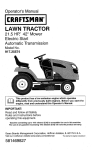
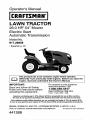
Operator's Manual
II
I_
I
IIIIIII
iCRRFTS.R.°!
LAWN TRACTOR
26.0 HR* 54" Mower
Electric Start
Automatic Transmission
Model No.
917.28858
- Espa_ol, p. 37
differently from previously built engines. Before you start the
engine, read and understand this Owner's Manual.
IMPORTANT:
Read and follow all Safety
Rules and Instructions before
operating this equipment.
For answers to your questions
about this product,Call:
1-800-659-5917
Sears Craftsman Help Line
5 am - 5 pm, Mon - Sat
Gasoline containing up to 10% ethanol (EIO) is acceptable for use in this machine.
The use of any gasoline exceeding 10% ethanol (El0) will void the product warranty.
Esta mdquina puede utilizar gasolina con un contenido de hasta el 10% de etanol (El0).
El uso de una gasolina que supere el 10% de etanol (EIO) anular& la garantia del producto.
SEARS, ROEBUCK AND CO., HOFFMAN ESTATES, IL 60179 U.S.A.
Visit our Craftsman website:www.sears,com/craftsman
*_ rated
bythe
engine
manufacturer
441269
Maintenance ........................................... 21
Service and Adjustments ....................... 26
Storage .................................................. 31
Troubleshooting ..................................... 32
Sears Service .......................... Back Cover
Warranty .................................................. 2
Safety Rules ............................................ 3
Product Specifications ............................. 6
AssemblyiPre-Operation ......................... 7
Operation ............................................... 13
Maintenance Schedule .......................... 21
Craftsman Riding Equipment Warranty
CRAFTSMAN FULL WARRANTY
FOR TWO YEARS from the date of purchase, all non-expendable parts of this ridingequipment are
warranted against any defects in material or workmanship. A defective non-expendable part will
receive free in-home repair or replacement if repair is impossible.
FOR FIVE YEARS from the date of purchase, the frame and front axle of this riding equipment are
warranted against any defects in material or workmanship. A defective frame or front axle will receive
free in-home repair or replacement if repair is impossible.
FOR 90 DAYS from the date of purchase, the batter,j (an expendable part) of this riding equipment
is warranted against any defects in material or workmanship (our testing proves that it will not hold a
charge). A defective battery will receive free in-home replacement,
ADDITIONAL LIFETIME LIMITED WARRANTY on CAST IRON FRONT AXLE (if equipped)
FOR AS LONG AS IT iS USED by the originalowner after the fifth year from the date of purchase, the
cast iron front axle (if equipped) of this riding equipment is warranted against any defects in material or
workmanship. With proof of purchase, a defective cast front axle wilI receive free in-home replacement.
WARRANTY SERVICE
For warranty coverage details to obtain free repair or replacement, call 1-800-659-5917 or visit the
web site: www.craftsman.cem
fn all cases above, if part repair or replacement is impossible, the riding equipment will be replaced
free of charge with the same or an equivalent model.
All of the above warranty coverage is void if this riding equipment is ever used white providing
commercial services or if rented to another person.
This warranty covers ONLY defects in material and workmanship. Warranty coverage does NOT
include:
• Expendable parts (except battery) that can wear out from normal use within the warranty period,
including but not limited to blades, spark plugs, air cleaners, belts, and oil filters.
• Standard maintenance servicing, oil changes, or tune-ups.
• Tire replacement or repair caused by punctures from outside objects, such as nails, thorns,
stumps, or glass.
• Tire or wheel replacement or repair resulting from normal wear, accident, or improper operation or
maintenance.
• Repairs necessary because of operator abuse, including but not limited to damage caused by
towing objects beyond the capability of the riding equipment, impacting objects that bend the
frame, axle assembly or crankshaft, or over-speeding the engine.
• Repairs necessary because of operator negligence, including but not limited to, electrical and
mechanical damage caused by improper storage, failure to use the proper grade and amount
of engine oil, failure to keep the deck clear of flammable debris, or failure to maintain the dding
equipment according to the instructions contained in the operator's manual.
- Engine (fuel system) cleaning or repairs caused by fuel determined to be contaminated or oxidized
(stale). tn general, fuel should be used within 30 days of its purchase date.
• Normal deterioration and wear of the exterior finishes, or product label replacement.
This warranty gives you specific legal rights, and you may also have other rights which vary from
state to state.
Sears Brands
Management
Corporation,
Hoffman
2
Estates,
IL 60179
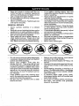
_DANGER:
This cutting machine is capable of amputating hands and feet and
throwing objects. Failure to observe the following safety instructions could result
in serious injury or death.
__WARNING: In orderto prevent accidental starting when setting up, transporting,
adjusting or making repairs, always disconnect spark plug wire and place wire where
it cannot contact spark plug.
•
Never directdischarged material toward
anyone. Avoid discharging material
against a wall or obstruction. Material
may ricochet back toward the operator.
Stop the blades when crossing gravel
surfaces.
_WARNING:
Do not coast down a hill in • Do not operate machine without the enneutral, you may lose control of the tractor.
tire grass catcher, discharge chute, or
othersafetydevices inplaceand working.
_IbWARNING: Tow onty the attachments
• Slow down before turning.
that are recommended by and comply with
• Never leave a running machine unatspecifications of the manufacturer of your
tended. Always turn off blades, set
tractor. Use common sense when towing.
parking brake, stop engine, and remove
Operate only at the lowest possible speed
keys before dismounting.
when on a slope. Too heavy ofa load, while • Disengage blades when not mowing.
on a stope, is dangerous. Tires can lose
Shut off engine and wait for all parts to
traction with the ground and cause you to
cometo a complete stop before cleaning
lose control of your tractor.
the machine, removing the grass catcher,
or unclogging the discharge chute.
_WARNING:
Engine exhaust, some of
• Operate machine only indaylight orgood
its constituents, and certain vehicle compoartificiallight.
nents contain or emit chemicals known tothe
• Do notoperate the machine while under
State of California to cause cancer and birth
the influence of alcohol or drugs.
defects or other reproductive harm.
• Watch for traffic when operating near or
_WARNING: Battery posts, terminals and
crossing roadways.
- related accessories contain lead and lead
• Use extra carewhen loading or unloading
the machine into a trailer or truck.
compounds, chemicals known to the State of
California to cause cancer and birth defects
• AIwaysweareye protection when operator other reproductive harm. Wash hands
ing machine.
after handling.
• Data indicates that operators, age 60
years and above, are involved in a large
I. GENERAL OPERATION
percentage of riding mower-related injudes. These operators should evaluate
• Read, understand, andfollowallinstructions on the machine and in the manual
their abilityto operate the riding mower
............safely enough to protectthemselves and ......
................................
before starting.
others from serious injury.
• Do not put hands or feet near rotating
• Follow the manufacturer's recommenparts or under the machine. Keep clear
dation for wheel weights or counterof the discharge opening at all times.
weights.
• Only allow responsible adults, who are
• Keep machine free of grass, leaves or
familiar with the instructions, to operate
otherdebris build.up whichcan touchhot
the machine.
exhaust] engine parts and burn. Do not
• Clear the area of objects such as rocks,
allow the mower to plow leaves or other
toys, wire, etc., which could be picked
debris which can cause build-up to ocup and thrown by the blades.
cur. Clean any oil or fuel spillage before
• Be sure the area is clear of bystanders
operating or storing the machine. Allow
before operating. Stop machine _fanyone
machine to cool before storage.
enters the area.
• Never carry, passengers.
• Do not mow in reverse unless absolutely
necessary. Always Iookdownand behind
before and while backing.
II, SLOPE OPERATION
Slopes are a major factor related to loss of
control and tip-over accidents, which can
result in severe injury or death. Operation
on all slopes requires extra caution. If you
cannot back up the slope or ffyou feel uneasy
on it, do not mew it.
• Mow up and down slopes, not across.
° Watch for holes, ruts, bumps, rocks, or
other hidden objects. Uneven terrain
could overturn the machine. Tall grass
can hide obstacles.
° Choose a towground speed so that you
will not have to stop or shift while on the
slope.
• Do not mow on wet grass. Tires may lose
traction.
Always keep the machine in gear when
going down sJopes. Do not shift to neutral
and coast downhill
• Avoid starting, stopping, or turning on a
siope. Ifthetires losetraction, disengage
the blades and proceed slowly straight
down the slope.
• Keep all movement on the slopes stow
and graduat. Do not make sudden
changes in speed or direction, which
could cause the machine to roll over.
• Use extra care white operating machine
with grass catchers or other attachments;
they can affect the stability of the machine. Do no use on steep slopes.
° Do not try to stabilize the machine by
putting your foot on the ground.
Do not mow near drop-offs, ditches,
or embankments, The machine could
suddenly roll over ff a wheel is over the
edge or if the edge caves in.
Iil, CHILDREN
Tragic accidents can occur if the operator
is not alert to the presence of children.
Children are often attracted to the machine
and the mowing activity, Never assume
that children will remain where you last
saw them.
, Keep children out of the mowing area
and in the watchful care of a responsible
adult other than the operator.
• Be alert and turn machine off if a child
enters the area.
• Before and while backing, look behind
and down for small children.
•
Never carry children, even with the
blades shut off, They may fall off and
be seriously injured or interfere with safe
machine operation. Children who have
been given rides inthe past may suddenly
appear in the mowing area for another
ride and be run over or backed over by
the machine.
° Never allow children to operate the machine.
• Use extra care when approaching blind
corners, shrubs, trees, or other objects
that may block your view of a child,
IV, TOWING
• Tow only with a machine that has a hitch
designed fortowing. Do not attach towed
equipment except at the hitch point.
• Followthe manufacturer's recommendation for weightlimitsfor towed equipment
and towing on slopes,
• Never allow chiWdrenor others in or on
towed equipment.
• Onslopes, theweight ofthetowed equipment may cause loss of traction and loss
of control,
• Travel slowly and allow extra distance to
stop,
V. SERVICE
SAFE HANDLING OF GASOLINE
To avoid personal injury or property damage, use extreme care in handling gasoline.
Gasoline is extremely flammable and the
vapors are explosive.
• Extinguish all cigarettes, cigars, pipes,
and other sources of ignition,
° Use only approved gasoline container.
• Never remove gas cap or add fuel with
the engine running. Allow engine to coo]
before refueling.
• Never fuel the machine indoors.
• Never store the machine or fueicontainer
where there is an open flame, spark, or
pilot light such as on a water heater or
other appliances,
• Never fiJfcontainers inside a vehicle or
on a truck or trailer bed with plastic liner.
Always place containers on the ground
away from your vehicle when filling.
• Remove gas-powered equipment from
the truck or trailer and refuel it on the
ground. If this is not possible, then refuel
such equipmentwith a portable container,
rather than from a gasoline dispenser
nozzle.
4
-
Keep the nozzle in contact with the rim
of the fuel tank or container opening at
all times until fueling is complete. Do not
use a nozzle lock-open device.
• Iffuel is spilled on clothing, change clothing immediately.
• Never overfill fuel tank. Replace gas cap
and tighten securely,
GENERAL SERVICE
•
•
•
-
•
Never operate machine in a closed
area.
Keep all nuts and bolts tightto be sure the
equipment is in safe working condition.
Nevertamper with safety devices. Check
their proper operation regularly.
Keep machine free of grass, leaves, or
other debris build-up. Clean oil or fuel
spillage and remove any fuel-soaked debris. Allow machineto cool beforestodng.
Do not mow in reverse unless absolutely
necessary. Always tookdown and behind
before and while backing.
• Never carry children, even with the
blades shut off. They may fall off and
be seriously injured or interfere with safe
machine operation. Children who have
been given rides inthe pastmaysuddenly
appear in the mowing area for another
ride and be run over or backed over by
the machine.
• Keep children out of the mowing area
and in the watchful care of a responsible
adult other than the operator.
Be alert and turn machine off if a child
enters the area,
•
•
•
•
•
•
•
•
•
•
•
•
.
•
If you strike a foreign object, stop and
inspectthe machine. Repair, if necessary,
before restarting,
Never make any adjustments or repairs
with the engine running.
Checkgrass catcher components and the
discharge chute frequently and replace
with manufacturer's recommended parts,
when necessary.
Mowerbladesaresharp. Wraptheblade
or wear gloves, and use extra caution
when servicing them.
Checkbrakeoperationfrequently. Adjust
and service as required.
Maintain or replacesafety and instruction
labels, as necessary.
Be sure the area is clear of bystanders
before operating, Stop machine if anyone
enters the area.
Never carry passengers.
Before and while backing, took behind
and down for small children.
Mow up and down slopes (15° Max), not
across,
Choose a low ground speed so that you
will not have to stop or shift while on the
slope.
Avoid starting, stopping, or turning on a
slope. Ifthetireslosetraction, disengage
the blades and proceed slowly straight
down the slope.
If machine stops while going uphill,
disengage blades, shift into reverse and
back down slowly.
Do not turn on slopes unless necessary,
and then, turn slowly and gradually
downhill, if possible.
PRODUCT SPECIFICATIONS
!Gasoline Capacity 3 Galrons
and Type:
Unleaded Regular
Oil Type
(API-SG-SL):
SAE 30(above 32°F)
SAE 5W30(below 32°F)
Oil Capacity:
w/Filter:
w!o Filter:
Spark Plug:
Champion QC12YC
(Gap: .040")
Ground
Forward:
Reverse:
Speed
Charging System:
16 Amps
64 oz
60 oz
5.2
2.9
@ 3600 RPM
Battery:
AmpiHr:
Min, CCA:
Case size:
28
230
U1R
Blade Bolt
45-55 Ft. Lbs.
Torque:
CONGRATULATIONS on your purchase of
a new tractor. It has been designed, engineered and manufactured to give you the best
possible dependability and performance.
Should you experience any problem you cannot easily remedy, please contact a Sears or
other qualified service center.We have competent, well-trained representatives and the
proper tools to s_rvJce or repair this tractor.
Please read ar;d retain this manual. The
instructions wil__enable you to assemble
and maintain your tractor properly, Always
observe the "SAFETY RULES".
CUSTOMER
RESPONSIBILITIES
o Read and observe the safety rules.
and using your tractor.
i caring
ollow for
a regularschedule
in maintaining,
Follow the instructions under "Maintenance" and "Storage" sections of this
owner's manual.
_JlLWARNIN G: This tractor is equipped with
an internal combustion engine and should not
be used on or near any unimproved forestcovered, brush-covered or grass-covered
land unless the engine's exhaust system is
equipped with a spark arrester meeting applicable focal or state laws (ifany). If a spark
arrester is used, it should be maintained in
effective working order by the operator.
In the state of Californiathe above is required
by law (Section 4442 of the California Public
Resources Code). Other states may have
simitar laws. Federal laws apply on federat
lands. A spark arrester for the muffler is
availablethrough your nearest Sears service
center (See REPAIR PARTS manual).
REPAIR PROTECTION
AGREEMENTS
Congratulations on making asmart purchase.
Your new Craftsman® product is designed
and manufactured for years of dependable
operation. But like a[Iproducts, itmay require
repair from time to time. That's when having
a Repair Protection Agreement can save you
money and aggravation.
Purchase a Repair Protection Agreement
now and protect yourself from unexpected
hassle and expense.
Here's what's included in the Agreement:
•
Expertservicebyour12,000professional
repair specialists.
•
Unlimited service and no charge for parts
and labor on all covered repairs.
Product replacement if your covered
product can't be fixed.
•
•
Discount of 10% from regular price of
service and service-re)ated parts not
covered by the agreement; also, 10% off
regular price of preventive maintenance
check,
•
Fast help by phone - phone support
from a Sears representative onproducts
requiring in-homerepair, plus convenient
repair scheduling.
Once you purchase the Agreement, a
simple phone call is all that it takes for you
to schedule service, You can call anytime
day or night, or schedure a service appointment online.
Sears has over 12,000 professional repair
specialists, who have access to over 4,5
million quality parts and accessories, That's
the kind of professionalism you can count on
to help prolong the life of your new purchase
for years to come. Purchase your Repair
Protection Agreement today!
Some limitations and exclusions apply.
For prices and additional information call
1-800-827-6655.
SEARS INSTALLATION SERVICE
For Sears professional installation of home
appliances, garage door openers, water
heaters, and other major home items, inthe
U.S.A. call 1-800-4-MY-HOME®
Mower Front Wheel
©
(2) Rear _"_
Lift Link
(s) 1_/16
O.D, Washers
_
(1) Shoulder Bolt
(1) 1-1/40.D.
Washer
Assemblies
(1) Small
Retainer Springs
(5) Large
Retainer Springs
©
(1) Front _\
Lift Link
"_
(1) Wheel
Assembly
®
(1) Anti-Sway Bar
(1)3/8-1s
Loeknut
Slope Sheet
Keys
(1) 3/40.D.
Washers
(2) Keys
(1) Small Retainer
Springs
@
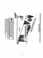
Your new tractor has been assembled at the factory with exception of those parts left unassembled for shipping purposes. To ensure safe and proper operation of your tractor all parts
and hardware you assemble must be tightened securely. Use the correct tools as necessary
to ensure proper tightness,
TOOLS
REQUIRED
FOR ASSEMBLY
•
Reiease lever to lock seat in position.
A socket wrench set wilt make assembly
easier. Standard wrench sizes are listed,
(2) 7/t 6" wrenches
Utility knife
(1) 1/2" wrench
(1) 3/4" wrench
Tire pressure gauge
Pliers
(1) 3/4" socket w!drive ratchet
(1) 9/I 6" wrench
Flashlight
When right or left hand is mentioned in this
manual, it meanswhen you are in the operating
position (seated behind the steering wheel).
TO
REMOVE
CARTON
UNPACK
•
•
•
•
TRACTOR
FROM
CARTON
Removeall accessibleloose parts and parts
cartons from carton,
Cut along dotted lines on all four panels of
carton. Remove end panels and lay side
panels flat,
Remove mower and packing materi_s.
Check for any additional loose parts or
cartons and remove.
BEFORE
REMOVING
FROM SKID
TO CHECK
TRACTOR
BATTERY
1, Lift hood to raised position.
NOTE: If this battery is put into service after
month and year indicated on label (label is
located between terminals) charge battery
for minimum of one hour at 6-10 amps. (See
"BA'I-FERY" in Maintenance
section of this
manual for charging instructions).
•
For battery & battery cable installation see
"REPLACING BATTERY" in the "Service
and Adjustments" section in this manual,
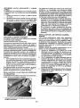
TO ADJUST
•
•
SEAT
Sit in seat,
Lift up adjustment lever (A) and slide seat
until acomfortable position is reached which
allows you to press clutch!brake pedal all
the way down.
NOTE: You may now roll your tractor off the
skid. Follow the appropriate instruction below
to remove the tractor from the skid.
WARNING: Before starting, read, understand and follow all instructions in the Operation
section of this manual. Be sure tractor is in a
well-ventilated area, Be sure the area in front
of tractor is clear of other people and objects.
TO ROLL TRACTOR OFF SKID (See
Operation
section
for location
and
function
of controls)
I, Raise attachment lift lever to its highest
position.
2. Release parkZng brake bydepressing brake
pedal,
3, PEacefreewheel control in disengaged position to disengage transmission (See 'q'O
TRANSPORT" in the Operation section of
this manual).
4, Roll tractor forward off skid,
Continue with the instructions that follow.
TO INSTALL
MOWER
1. SET PARKING BRAKE LEVER AND
LOWER ATTACHMENT LIFT LEVER
•
Depress clutch/brake pedal all the way
down and hold.
•
Pull parking brakelever up and hold, release
pressure from clutch/brake pedal, then
release parking brake lever. Pedal should
remain in brake position, Ensure parking
brake will hold tractor secure,
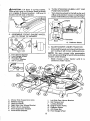
,I_CAUTION: Lift lever is spring loaded.
Have a tight grip on lift lever, lower it slowly
and engage in lowest position. Lift lever is
located on left side of fender,
Lift
Lever
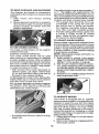
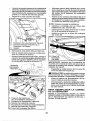
2. ASSEMBLE
FRONT GAUGE
(W) TO FRONT OF MOWER
3. TURN STEERING WHEEL LEFT AND
POSITION MOWER
• Turn steering wheel to the left as far as it
will go and position mower on right side of
tmctorwith deflectorshield (Q)tothe right,
Front
WHEEL
Q. Deflector Shield
H.
W.
X.
Y,
Z.
Front Mower Bracket
Front Gauge Wheel
Shoulder Bolt
1-1/40,D. Washer
3/8-16 Locknut
A.
B.
C,
D,
E.
E
H.
Mower Side Suspension Arms
Retainer Spring
Rear Lift Link(S)
Right Side Rear Mower Bracket
Front Lift Link Assembly
Front Suspension Bracket
Front Mower Bracket
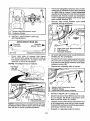
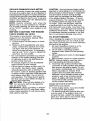
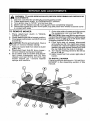
4, SLIDE MOWER UNDER TRACTOR
• Bring beltforward and check beltfor proper routing in all mower pulley grooves,
NOTE: Be sure mower side suspension
arms (A) are pointing forward before sliding
mower under tractor.
• Slide mower under tractor until it is
centered under tractor,
I,
K,
L
M,
Q.
S.
W.
Left Side Rear Mower Bracket
Belt Tension Rod
Locking Bracket
Engine Clutch Pulley
Deflector Shield
Anti-Sway Bar
Front Gauge Wheel
•
•
Pivot the integrated washer end of antisway bar (S)towards mowerdeck bracket
on right side of mower, Insert integrated
washerend of bar into hole inrear mower
bracket (D). Move mower as needed to
insert integrated washer end of bar into
rear mower bracket (D).
Secure with small washer and small
retainer spring as shown.
A. Mower
Side
Suspension
Arms
Q.Deflector
Shield
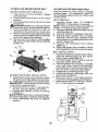
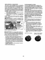
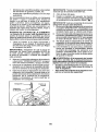
5. INSTALL ANTI-SWAY BAR (S)
(IF EQUIPPED)
_
ANTI-SWAY
Towards
Transaxle
90° End
•
BAR ($)
Towards
Mower Deck
D. Right Side RearMowerBracket
S, Anti-Sway Bar
T TransaxleBracket
IntegratedWasherEnd
/
From right side of mower, first insert
90° end of anti-sway bar (S) into hole in
transaxle bracket El'), located near left
rear tire in front of transaxle,
NOTE: Flashlight may be helpful.
Anti-Sway
Bar (S)
_:
.........
_'°_!
i
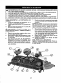
6. ATTACH MOWER SIDE SUSPENSION
ARMS (A) TO CHASSIS
• Position front hole inside suspension arm
(A) over pin on outside of tractor chassis
and secure with large washer and large
retainer spring (B).
, Repeat on opposite side of tractor.
""
Transaxle Bracket (T)
Located Between Rear Tires
A, Mower Side Suspension Arms
B, Retainer Spring
D. Right Side Rear Mower Bracket
7, ATTACH REAR LIFT LINKS (C)
• Insert rod end of rear lift link (C) into hole
(U) in tractor lift shaft suspension arm
and pivot link down to mower.
• Uft rear corner of mower and position slot
in link assembly over pin on rear mower
bracket (D) and securewith fargewasher
and large retainer spring.
• Repeat on opposite side of tractor.
NOTE: Depending on model, bracket (_ may
be differentthan shown but hole foranti-sway
bar wilt be in same position/location.
10
9
•
•
INSTALL BELT ON ENGINE CLUTCH
PULLEY (M)
Disengage belt tension rod (K) from
locking bracket (L),
Install belt onto engine clutch pulley (M),
C. Rear Lift Link(s)
D. Ri9ht Side Rear Mower Bracket
_U, Hole
8 A-FFACHFRONT LINK (E)
* Turn steering wheel to position wheets
straight forward,
* From front of tractor, insert rod end of
front link (E) through front hole in tractor
front suspension bracket (F).
. Moveto left side of mower and and insert
large retainer spring (G) through hole in
front link (E) behind front suspension
bracket (F).
- Insert other end of link (E) into hole in
front mower bracket (H) and secure with
washer and small retainer spring (J).
NOTE: Requires deck lifting.
f_
Front Link
Location,
IMPORTANT: Check belt for proper routing
in all mower pulley grooves and under
mandrel covers,
• Engage belt tension rod (K) on locking
bracket (L).
_ILCAUTION: Belt tension rod is spring
loaded. Have a tight grip on rod and engage
slowly.
• Raise attachment lift lever to highest
position.
• If necessary, adjust gauge wheels
before operating mower as shown in the
Operation section of this manual.
p-,
.21
/
-1
M,Engine
Clutch Pulley
/_
"
<_-_-_-_"
_\
MOWER DRIVE BELT INSTALLATION
Follow procedure described in "TO
REPLACE MOWER BLADE DRtVE BELT"
in the "Service and Adjustments" section of
this manual,
_.oi
M. Engine Clutch Pulley
11
CHECK TIRE PRESSURE
The tires on your tractor were overinflated
at the factory for shipping purposes. Correct tire pressure is important for best
cutting performance.
• Reduce tire pressure to PSI shown on
tires.
t//CHECKLIST
Before you operate your new tractor, we
wish to assure that you receive the best
performance and satisfaction from this
Quality Product.
Please review the following checklist:
i/" All assembly instructions have been
completed.
t/" No remaining loose parts in carton.
J Battery is properly
prepared and
charged,
J Seat is adjusted comfortably and tightened securely.
J All tires are propedy inflated. (For shipping purposes, the tires were overinflated
at the factory).
v! Be sure mower deck is properly leveled
side-te-sideifront-to-rear for best cutting
results. (Tires must be properly inflated
for leveling).
t/' Check mower and drive belts. Be sure
they are routed properly around pulleys
and inside all belt keepers.
Check wiring. See that all connections
are still secure and wires are properly
clamped.
vz Before driving tractor, be sure freewheel
control is in"transmission engaged" position (see "To Transport" in the Operation
section of this manual).
CHECK DECK LEVELNESS
For best cutting results, mower housing
should be properly leveled. See "TO
LEVEL MOWER" in the Service and Adjustments section of this manual.
CHECK FOR PROPER POSITION
OF ALL BELTS
See the figures that are shown for replacing motion and mower blade drive belts
in the Service and Adjustments section
of this manual. Verify that the belts are
routed correctly.
CHECK BRAKE SYSTEM
After you learn how to operate your tractor, check to see that the brake is operating properly. See "TO CHECK BRAKE"
in the Service and Adjustments section of
this manual.
While learning how to use your tractor, pay
extra attention to the following important
items:
i/" Engine oil is at proper level,
tZ" Fueltank is filledwithfresh, clean, regular
unleaded gasoline.
v_ Become familiar with all controls, their
location and function. Operate them
before you start the engine.
J" Be sure brake system is insafe operating
condition.
vt Be sure Operator Presence System and
Reverse Operation System (ROS) are
working properly (See the Operation and
Maintenance sections in this manual).
J It is important to purge the transmission
before operating your tractor for the first
time. Follow proper starting and transmission purging instructions (See "TO
START ENGINE" and "PURGE TRANSMISSION" in the Operation section ofthis
manual).
12
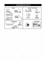
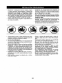
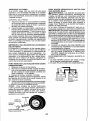
These symbols may appear on your tractor or in literature supplied with the product.
Learn and understand their meaning,
R
N
REVERSE
ENGINE
OFF
H
NEUTRAL
REVERSE
OPERATION
L
HIGH
ENGINE
SLeW
LOW
ON
ENGINE
IGNmON SWITCH
START
PARKING
BRAKE
MOWER
HEIGHT
MOWER
LIFT
SYSTEM(ROS)
LIGHTS
ON
FUEL
ATTACHMENT
CLUTCH DISENGAGED
BATTERY
REVERSE
ATTACHMENT
CL_;'t'CH ENGAGED
FORWARD
DANGER,
KEEP HANDS
AND FEET AWAY
CRUISECONTROL
KEEP
AREA
CLEAR
(SEE
SAFETYRULES
CLBTCWBRAKE
PEOAL
SLOPE
HAZARDS
SEC_ON)
DANGER
if not avoided,
will
result indicates
in death aorhazard
seriouswhich,
injury.
WARNING
hazard
which,
if not avoided,
could resultindicates
in deatha or
serious
injury,
FREE WHEEL
(Automatic Modets onIy)
CAUTION
indicates
a hazard
which, if
not avoided,
might result
in minor
or moderate
injury.
CAUTION when used without the alert symboI,
indicates a situation that could result in damage
to the tractor and!or engine.
Failure to follow instructions
could result in serious injury or
death. The safety alert symbol
is used to identify safety information about hazards which can
result in death, serious injury
andlor property damage,
HOT SURFACES indicates a hazard which,
if not avoided, could result in death, serious injury
and/or property damage,
FIRE indicates a hazard which, if not avoided,
could result in death, serious injury and!or
property damage.
13
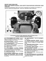
KNOW YOUR TRACTOR
READ THIS OWNER'S MANUAL AND SAFETY RULES BEFORE OPERATING YOUR
TRACTOR
Compare the illustrationswith your tractor to familiar{ze yourself with the locations of
various controls and adjustments. Save this manual for future reference.
Our tractors conform to the applicable safety standards of the
American National Standards Institute.
(A) ATTACHMENT LIFT LEVER - Used to
raise and towerthe mower or other attachments mounted to your tractor,
(H) LIGHT SWITCH - Turns the headlights
on and off,
(J) CRUISE CONTROL LEVER - Used to
set forward movement of tractor at desired
speed without holding the forward drive
pedal.
(B) BRAKE PEDAL- Used for braking the
tractor and starting the engine,
(C) PARKING BRAKE- Locks clutch/brake
pedal into the brake position.
(K) FORWARD DRIVE PEDAL - Used for
forward movement of tractor.
(D) THROTTLE CONTROL - Used to control engine speed.
(L) REVERSE DRIVE PEDAL- Used for
reverse movement oftractor.
(E) ATTACHMENT CLUTCH SWITCH
- Used to engagethe mower blades, or other
attachments mounted to your tractor.
(M) FREEWHEEL CONTROL- Disengages
transmission for pushing or slowly towing
the tractor with the engine off.
(N) CHOKE CONTROL- Used when starting a coid engine.
(F) IGNITION SWITCH - Used for starting
and stopping the engine.
(G) REVERSE OPERATION SYSTEM
(ROS) "ON" POSITION - Allows operation
of mower or other powe red attach ment while
in reverse.
(P) SERVICE REMINDER/HOURMETER
- Indicates when service is required for the
engine and mower.
14
The operation of any tractor can result in foreign objects thrown into
the eyes, which can result in severe eye damage. Always wear safety
glasses or eye shields while operating your tractor or performing any
adjustments or repairs. We recommend standard safety glasses or a
wide vision safety mask worn over spectacles.
HOW TO USE YOUR TRACTOR
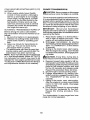
TO SET PARKING BRAKE
Your tractor is equipped with an operator
presence sensing switch. When engine is
running, any attempt bythe operatorto leave
theseatwithout first setting the parking brake
will shut off the engine,
1, Depress brake pedal (B) all the way down
and hold.
2. Pull parking brake lever (C) up and hold,
release pressure from brake pedal (B),
then release parking brake lever. Pedal
should remain in brake position. Make
sure parkingbrake will holdtractorsecure.
I
I
!
I
I
NOTE: Failure to move throttle control
between half and full speed (fast) position, before stopping, may cause engine
to "backfire".
• Turn ignition key (F) to "STOP" position
and remove key. Always remove key when
leaving tractor to prevent unauthorized
use.
• Never use choke (N) to stop engine.
IMPORTANT: Leaving the ignitionswitch in
any position other than "STOP" will cause
the battery to discharge and go dead.
NOTE: Undercertain conditions whentractor
is standing idle with the engine running, hot
engine exhaust gases may cause "browning" of grass. To eliminate this possibility,
always stop engine when stopping tractor
on grass
areas.
_IbCAUTION:
Always stop tractor completely,as described above, before leaving
the operator's position.
STOPPING
MOWER BLADES • To stop mower blades, push attachment
clutch switch into disengaged position (O).
(i) Attachment
Clutch Switch
Pull Out To "Engage"
TO USE THROTTLE CONTROL (D)
Always operate engine at full speed (fast).
• Operating engine at less than fult speed
(fast) reduces engine's operating efficiency.
• Full speed (fast) offers the best mower
performance.
(O) Push-in to
"Disengaged"
STOPPING
GROUND DRIVE • Tostop ground drive, depress brake pedal
all the way down.
ENGINE • Move throttle control (D) between half and
full speed (fast) position.
!5
TO MOVE
FORWARD
AND BACKWARD
The cutting height range is approximately 1"
to 4". The heights are measured from the
groundtothe bladetip withthe engine not run,
ning,These heights are approximate and may
vary depending upon soil conditions, height
of grass and types of grass being mowed,
• The average lawn should be cut to approximately 2-1/2" during the cool season and to over 3" during hot months.
For healthier and better looking lawns,
mow often and after moderate grov4h,
• For best cutting performance, grass over
6 inches in height should be mowed
twice. Make the first cut relatively high;
the second to desired height.
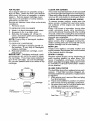
TO ADJUST GAUGE WHEELS
Gauge wheels are properlyadjusted when
they are slightly off the ground when mower
is at the desired cutting height in operating
position, Gauge wheels then keep the deck
in proper position to help prevent scalping
in most terrain conditions.
NOTE: Adjust gauge wheels with tractor on
a flat level surface,
1, Adjust mower to desired cutting height
(See "TO ADJUST MOWER CUTTING
HEIGHT" in this section of manual).
2. With mower in desired height of cut position, gaugewheelsshould be assembled
so they are slightly off the ground. Install
gaugewheel inappropriate hole,Tighten
securely.
3. Repeat for all, installing gauge wheel in
same adjustment hole.
The direction and speed of movement is
controlled by the forward and reverse drive
pedals.
1, Start tractor
and release
parking
brake,
2, Slowly depress forward (K) or reverse(L)
drive pedal to begin movement. Ground
speed increases the further down the
pedal is depressed.
TO USE CRUISE CONTROL
The cruise control feature can be used for
forward travel only.
SYSTEM CHARACTERISTICS
The cruise control should only be used
while mowing or transporting
on relatively
smooth, straight surfaces. Other conditions
such astrimming
at slowspeeds may cause
the cruise control to disengage. Do not use
the cruise control on slopes, rough terdan
or while trimmimg or turning.
• With forward drive pedal depressed to
desired speed, pull cruise control lever
(J) up and hold while lifting your foot off
the pedal, then release the lever.
To disengage the cruise control, depress the
brake pedal, tap on forward drive pedal or
push the cruise control lever down.
TO ADJUST MOWER CUTTING HEIGHT
The position of the attachment
determines the cutting height.
• Put attachment
height slot.
lift lever (A)
TO OPERATE MOWER
Your tractor is equipped with an operator
presence sensing switch. Any attempt bythe
operator to leave the seat with the engine
running and the attachment clutch engaged
will shut off the engine. You must remain
fully and centrally positioned in the seat to
prevent the engine from hesitating or cutting
offwhen operating your equipment on rough,
rolling terrain or hills,
1. Select desired height of cut with attachment lift lever.
2. Start mower blades by engaging attachment clutch control,
lift lever in desired cutting
16
TO STOP MOWER BLADES • Disengage attachment clutch control.
_CAUTION:
Do not operate the mower
without either the entire grass catcher, on
mowers so equipped, orthe deflector shield
(S) in place.
REVERSE OPERATION SYSTEM (ROS)
Your tractor is equipped with a Reverse
Operation System (ROS). Any attempt by
the operatorto travelin the reversedirection
with the attachment clutchengaged willshut
offthe engine unless ignitionkey is placed
in the ROS "ON" position.
_WARNING:
Backing up with the attachment clutch engaged while mowing
is strong[y discouraged. Turning the ROS
"ON", to allow reverse operation with the
attachment clutch engaged, should only
be done when the operator decides it is
necessary to reposition the machine with
the attachment engaged. Do not mow in
reverse unless absolutely necessary.
USING THE REVERSE OPERATION
SYSTEM Only use if you are certain no children or
other bystanders willenter the mowing area.
I. Depress brake pedal all the way down.
2. With engine running, turn ignition key
counterclockwise to ROS "ON" position.
3, Look down and behind before and
while backing,
4. Slowly depress reverse drive pedal to
start movement.
5. When use of the ROS is no longer
needed, turn the ignition key clockwise
to engine "ON" position.
ROS "ON" Posilion
Engine "ON" Position
(Normal Operating)
17
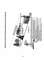
TO OPERATE ON HILLS
_WARNING:
Do not drive up or down
hillswith slopesgreater than 15° and do not
drive across any slope. Use the slopeguide
provided at the back of this manual.
• Choose the slowestspeed before starting
up or down hills.
, Avoid stoppingor changingspeed on hills,
- If stopping is absolutelynecessary, push
brake pedal quicklyto brake position and
engage parking brake.
• To restartmovement, slowlyrelease parking brake and brake pedal
• Slowlydepress appropriate drive pedalto
slowest setting.
° Make all turns slowly.
TO TRANSPORT
When pushing or towing your tractor, be
sure to disengage transmission by placing
freewheel control in freewheeling position.
Free wheel control is located at the rear
drawbar of tractor.
• Raise attachment lift to highest position
with attachment lift control.
• Pull freewheel controloutand into the slot
and release so it is held inthe disengaged
position,
- Do not push or tow tractor at more than
two (2) MPH.
• Toreengage transmission, reverse above
procedure.
NOTE: Toprotect hood from damage when
transporting your tractor on atruck or atrailer,
besure hood is closed and secured to tractor.
Use an appropriate means of tying hood to
tractor (rope, cord, etc.).
TOWING CARTS AND OTHER ATTACHMENTS
Tow onlythe attachments that are recommended by and comply with specifications
of the manufacturer of your tractor.Use
common sense when towing. Too heavy
of a load, while on a slope, is dangerous.
Tires can lose tractionwith the ground and
cause you to lose controlof your tractor.
SERVICE REMINDER/HOUR METER
Service reminder shows the total number
of hours the engine has run and flashes to
indicatethat the engine or mower needs servicing, When service is required, the service
reminder wi]] flash for two hours. To service
engine and mower, see the Maintenance
section of this manual.
NOTE: Service reminder runs when the
ignition key is in any position but "STOP".
For acurate reading, be sure key remains
in the "STOP" position when engine is not
running.
BEFORE STARTING THE ENGINE
CHECK ENGINE OIL LEVEL
The engine in your tractor has been
shipped, from the factory, already filled
with summer weight oil.
1, Check engine oil with tractor on level
ground.
2. Remove oil fill cap/dipstick and wipe
clean, reinsert the dipstick and screw
cap tight, wait for a few seconds, remove and read oil level. If necessary,
add oil until "FULl" mark on dipstick is
reached, Do not overfill
• For cold weather operation you should
change eit for easier starting (See the
oil viscosity chart in the Maintenance
section of this manual).
• To change engine oil, see the Maintenance section in this manual
• Fill fuel tank to bottom of filler neck. Do
not overfill. Use fresh, clean, regular
unleaded gasoline with a minimum of
87 octane. (Use of leaded gasoline will
increase carbon and lead oxide deposits
and reduce valve life). Do not mix oil
with gasoline. Purchase fuel in quantities that can be used within 30 days to
ssure fuel freshness.
CAUTION: Wipe off any spilled oil or
• Do not store, spill or use gasoline
near an open flame.
IMPORTANT: When operating in temperatures below 32°F(0°C), use fresh, clean
winter grade gasoline to help insure good
cold weather starting.
CAUTION: Alcohol blended fuels (called
gasohol or using ethanol or methanol) can
attract moisture which leads to separation
and formation of acids during storage.
Acidic gas can damage the fuel system
of an engine while in storage. To avoid
engine problems,the fuel system shou]d
be emptied before storage of 30 days
or longer. Drain the gas tank, start the
engine and let it run until the fuel lines
and carburetor are empty. Use fresh fuel
next season. See Storage Instructions for
additional information. Never use engine
or carburetor cleaner products in the fuel
tank or permanent damage may occur,
TO START ENGINE
When starting the engine for the first time
or if the engine has run out of fuel, it will
take extra cranking time to move fuel from
the tank to the engine.
1. Be sure freewheel control is in the
transmission engaged position.
2. Sit on seat in operating position,
depress brake pedal and set parking
brake.
3. Move attachment clutch to disengaged
position,
4. Move throttle control to choke position.
NOTE: Before starting, read the warm
and cold starting procedures below.
5, insert key into ignitionand turn key
clockwise to start position and release
key as soon as engine starts. Do not
run starter continuously for more than
fifteen seconds per minute, if the
engine does not start after several
attempts, move throttle control to fast
position, wait a few minutes and try
again. If engine still does not start,
move the throttle control back to the
choke position and retry,
WARM WEATHER STARTING
(50°F(10°C) and above')
6. When engine starts, move the throttle
control to the fast position.
• The attachments and ground drive can
now be used• If the engine does not
accept the load, restart the engine and
allow it to warm up for one minute using
the choke as described above.
18
PURGE TRANSMISSION
COLD
WEATHER
STARTING
(50°F(10°C)
andbelow)
_LCAUTION: Never engage or disengage
6. When
engine
starts,
leave
throttle
control
inchoke
position
untilengine freewheel leverwhile the engine is running.
warms
upandbegins
torunroughly. Toensure properoperation andperformance,
Oncerough
running
begins,
immedi- it is recommended that the transmission be
atelymove
thethrottle
control
tothe
purged before operating tractorfor the first
fastposition.
Engine
warm-up
may
procedure will remove anytrapped
takefromseveral
seconds
toseveral time.This
air inside the transmission which may have
minutes
(thecolder
thetemperature, developed during shipping of your tractor.
thelonger
thewarm-up).
Should your transmission
AUTOMATIC
TRANSMISSION
WARM
UP IMPORTANT:
require removalfor service or replacement,
Before
driving
theunitincoldweather, it should be purged after reinstallation before
thetransmission
should
bewarmed
upas operating the tractor.
follows:
1. Besurethetractor
isonlevelground. 1. Place tractor safely on a level surface that is clear of objects and open - with
2. Release
theparking
brake
andletthe
engine off and parking brake set.
brake
slowly
return
tooperating
posi2. Disengage transmission by placing
tion.
freewheel control indisengaged position
3. Allowoneminute
fortransmission
to
(See "TO TRANSPORT" in this section
warmup.Thiscanbedoneduring
of manual).
theengine
warmupperiod.
• Theattachments
canalsobeuseddur- 3. Sitting in the tractor seat, start engine.
After the engine isrunning, move throttle
ingtheengine
warm-up
period
afterthe
control to slow position. Disengage parktransmission
hasbeenwarmed
up.
Jngbrake.
NOTE;
Ifatahigh
altitude
(above
3000
feet)
orincoldtemperatures
(below
32°F(0°C))_CAUTION: At any time, during step 4,
thecarburetor
fuelmixture
mayneed
tobe there may be movement of the drive wheels.
adjusted
forbestengine
performance
(see
4. Depress forward drive pedal to full for"TOADJUST
CARBURETOR"
intheService
ward positionandhold forfive (5)seconds
andAdjustments
section
ofthismanual).
5.
6,
7.
8.
and release pedal. Depress reverse drive
pedal to full reverse position and hold
for five (5) seconds and release pedal.
Repeat this procedure three (3) times,
Shutoff engine and set parking brake.
Engage transmission by placing freewheel control in engaged position (See
"TO TRANSPORT" in this section of
manual).
Sitting in the tractor seat, start engine,
After the engine is running, move throttle
control to half (1/2) speed. Disengage
parking brake.
Drive tractor forward for approximately
five feet then backwards for five feet.
Repeat this driving procedure three
times.
Your transmission is now purged and now
ready for normal operation.
19
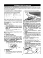
MOWING TIPS
Tire chains cannot be used when the
mower housing is attached to tractor,
• Mower should be properly leveled for best
mowing performance. See "TO LEVEL
MOWER HOUSING" in the Service and
Adjustments section of this manual.
• The left hand side of mower should be
used for trimming.
• D rive sothat clippings are discharged onto
the areathat has already been cut. Have
the cut area to the right ofthe tractor. This
wiU result in a more even distribution of
clippings and more uniform cutting.
• When mowing large areas, start byturning
to the right so that clippings wilt discharge
away from shrubs, fences, driveways,
etc. After one or two rounds, mow in the
opposite direction making left hand turns
until finished.
,
r
• If grass is extremely tall, it should be
mowed twice to reduce load and possible
fire hazard from dried clippings. Make
first cut relatively high; the second to the
desired height.
• Do not mow grass when it is wet, Wet
grass will plug mower and leave undesirable clumps. Allow grass to dry before
mowing,
• Always operate engine at full throttle
when mowing to assure better mowing performance and proper discharge
of material. Regulate ground speed by
selecting a low enough speed to give the
mower cutting performance as well as the
quality of cut desired.
• When operating attachments, select a
ground speed that will suit the terrain and
give best performance of the attachment
being used.
2O
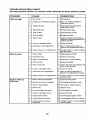
MAINTENANCE
SCHEDULE
Check
Brake
Check
Tire
Operation
Pressure
C_eck Operator Presence &ROS Systems
Check
for Loose
Fasteners
C
ChecklR_place
T
IJJbrlcat_on
0
Check
R
CleaP'BattswandTetminals
Clean
Mower
I ._FOr_EEW_ _v=.v.... EV_
_v
_E_.........
B_rOR_
_CH
s
_
to
10o s_so_ s_P-_
use
.ouRs
.ou.s
HOU.S
.ouRs
V
P
If
V
_
_
........
If'
:tl_
................
Blades
Chart
aatte_
Debris
_4
I
Steering
P|ate
Mower
If
I
Ik##
V_s
Check Transaxle Cooling
,,Check
..........................
,V
Leve,lness
'
'
Check V-Belrs
Check
Chanqe
C han_
En_llne
V'
Oil
Level
Br_git',e Oil
Bngir_e
(with
Oil (wlthout
_
If
,V'_
oil fi_ter)
t_fl,=
............
i ,,, _
i_
Clean
Screen
_nspect Ail"
MuffleriS
_1
Rap=ace Oil Filter (If equipped)
CtBan Engine
Cooling
Fins
Fleplace
Fuel
V_2
ark Arrester
Replace Spark Plug......
Air Filter
I
oil filter)
Clean Air FIIN,r
Replace
V
V F
Level
Off
_
Jf,_
'
I_'
J
V 4
....................
V"
Ibm",=
V* =
I
............
If
Paper Cartridge
I
, If
.....
_l_
Filter
,,, V'
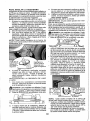
GENERAL RECOMMENDATIONS
The warranty on this tractor does not cover
items that have been subjected to operator
abuse or negligence, To receive full value
from the warranty, operator must maintain
tractor as instructedin this manual.
Some adjustments will need to be made periodically to properly maintain your tractor,
At least once a season, check to see if
you should make any of the adjustments
described in the Service and Adjustments
section of this manual
, At least once a year you should replace
the spark plug, clean or replace air filter,
and check blades and belts for wear. A
new spark plug and clean air filter assure
proper air-fuel mixture and hetp your engine run better and last longer.
BEFORE EACH USE
I. Check engine oil level.
2. Check brake operation.
3, Check tire pressure,
4. Check operator presence and
ROS systems for proper operation.
5. Check for loose fasteners.
LUBRICATION CHART
_)Steering Pivot Bolts
Zerk
Zerk
(_
_/heel
Bearing
Wheel
Zerk
_Beadng
Steerir
_,_J"@
Gear
=
Teeth
L_
Zerk
Engine
_) Mandrel
Zerks
(_)General Purpose Grease
(_)Refer to Maintenance"ENGINE" Section,
IMPORTANT: Do not oil or grease the pivot
points which have special nylon bearings.
Viscous lubricantswill attract dust and dirt
thatwillshortenthe lifeofthe seff-|ubricating
bearings, lfyou feelthey must be lubricated,
use only a dry, powdered graphite type
lubricantsparingly.
21
TRACTOR
Always observe safety rules when performing any maintenance.
BRAKE OPERATION
if tractor requires more than five (5) feet to
stop at highest speed in highest gear on a
level, dry concrete or paved surface, then
brake must be serviced. (See "TO CHECK
BRAKE" in the Service and Adjustments
section of this manual).
TIRES
• Maintain proper air pressure in all tires
(See PSI on tires).
Keep tires free of gasoline, oil, or insect
control chemicals which can harm rubbet.
- Avoid stumps, stones, deep ruts, sharp
objects and other hazards that may
cause tire damage.
NOTE: To seal tire punctures and prevent
flat tires due to slow leaks, tire sealant
may be purchased from your local parts
dealer. Tire sealant also prevents tire dry
rot and corrosion.
OPERATOR PRESENCE SYSTEM AND
REVERSE OPERATION SYSTEM (ROS)
Be sure operator presence and reverse
operation systems are working properly. If
your tractor does not function as described, repair the problem immediately,
• The engine should not start unless the
brake pedal is fully depressed, and
the attachment clutch control is in the
disengaged position.
CHECK OPERATOR PRESENCE
SYSTEM
° When the engine is running, any attempt by the operator to leave the seat
without first setting the parking brake
should shut off the engine.
• When the engine is running and the
attachment clutch is engaged, any attempt by the operator to leave the seat
should shut off the engine.
° The attachment clutch should never operate unless the operator is in the seat.
ROS "ON" Position
Engine "ON" Position
(Normal Operating)
22
CHECK REVERSE OPERATION (ROS)
SYSTEM
• When the engine is running with the
ignition switch in the engine "ON" position and the attachment clutch engaged,
any attempt by the operator to shift into
reverse should shut offthe engine.
° When the engine is running with the
ignition switch in the ROS "ON" position
and the attachment clutch engaged,
any attempt by the operator to shift into
reverse should NOT shut off the engine,
BLADE CARE
For best results mower blades must be
sharp. Replace worn, bent or damaged
blades.
CAUTION: Use only a replacement
blade approved by the manufacturer of
your tractor. Using a blade not approved
by the manufacturer of your tractor is
hazardous, could damage your tractor and
void your warranty.
BLADE REMOVAL
I, Raise mower to highest position to alIow
access to blades.
NOTE: Protect your hands with gloves and/
or wrap blade with heavy cloth.
2. Remove blade bolt by turning counterclockwise.
3. Instaltnewbladewith stamped"THJSSIDE
UP" facing deck and mandrel assembly.
IMPORTANT: To ensure proper assembly,
center hole in blade must align with star on
mandrel assembly.
4. Install and tighten blade bolt securely
(45-55 Ft. Lbs. torque).
IMPORTANT: Special blade bolt is heat
treated.
Mandrel
Assembly
Blade
/-,
.--__J
BATTERY
Your tractor has a battery charging system
which is sufficientfor normal use. However,
periodic charging of the battery with an automotive charger will extend its life.
• Keep battery and terminals clean.
• Keep battery bolts tight.
• Keep small vent holes open,
• Recharge at 6-10 amperes for 1 hour.
NOTE: The original equipment battery on
your tractor is maintenance free. Do not
attempt to open or remove caps or covers.
Adding or checking level of electrolyte is
not necessary.
TO CLEAN BATTERY AND TERMINALS
Corrosion and dirt on the battery and terminals can cause the battery to "leak" power.
1. Remove terrninal guard.
2. Disconnect BLACK battery cable first
then RED battery cable and remove
battery from tractor.
3. Rinsethe batterywith plain waterand dry.
4. Clean terminals and battery cable ends
with wire brush until bright.
5. Coat terminals with grease or petroleum
jelly.
6. Reinstall battery (See "REPLACING
BAKERY" in the SERVICE AND ADJUSTMENTS section of this manual).
TRANSAXLE COOLING
Keep transaxle free from build-up of dirt and
chaff which can restrict cooling.
V-BELTS
Check V-beits for deterioration and wear after
100 hours of operation and replace if necessary. The belts are not adjustable. Replace
belts if they begin to slip from wear.
ENGINE
LUBRICATION
Only use high quality detergent oil rated
with API service classification SG-SL,
Select the oil's SAE viscosity grade
according to your expected operating
temperature.
S_EVJscgsJ_G_OES
I
• Be sure tractor is on level surface.
• Oil will drain more freely when warm.
- Catch oil in a suitable container.
1. Remove oil fill cap/dipstick. Be careful
notto allow dirt to enter the engine when
changing oil.
2. Slideoil drain extensionfromthe docking
position on the engine blower housing
and extend outward from engine.
pDoOCking
sition
Oil Drain
3. To open, twist cap counter-clockwise
4. After oil is drained completely, replace
cap and twist clockwise until it stops.
5. Re-attach oil drain extension to engine
blower housing.
6. Refitfengine with oil through oilfill dipstick
tube. Pourslowly. Do not overfill. For approximate capacity see "PRODUCT SPECIFICATIONS" section of this manual.
7. Use gauge on oil fill cap/dipstick for
checking level. For accurate reading,
tighten dipstick cap securely onto the
tube before removing dipstick. Keep oil
at "FULE line on dipstick. Tighten cap
onto the tube securely when finished.
ENGINE OIL FILTER
Replace the engine oil filter every season or
every other oil change if the tractor is used
more than 100 hours in one year.
NOTE: Although multi-viscosity oils
(5W30, 10W30 etc.) improve starting in
cold weather, they will result in increased
oi! consumption when used above 32°F.
Check your engine oil level more frequently to avoid possible engine damage from
running low on oil.
Change the oil after every 50 hours of operation or at leastonce a year if the tractor
is not used for 50 hours in one year.
Check the crankcase oil level before
starting the engine and after each eight
(8) hours of operation. Tighten oil filr cap/
dipstick securely each time you check the
oil level.
TO CHANGE ENGINE OIL
Determine temperature range expected
before oil change. All oil must meet API
service classificationSG-SL.
23
AIR FILTER
Your engine will not run properly using a
dirb] air filter. Clean the foam pre-cleaner
after every 25 hours of operation or every
season. Service paper cartridge every
100 hours of operation or every season,
whichever occurs first.
Service air cleaner more often under dusty
conditions.
1. Remove cover,
TO SERVICE PRE-CLEANER
2, Wash it in Iiquid detergent and water.
3. Squeeze it dry in a clean cloth.
4. Saturate it in engine oil. Wrap it in
clean, absorbent cloth and squeeze to
remove excess oil.
NOTE: If very dirty or damaged, replace
pre-cleaner.
TO SERVICE CARTRIDGE
1. Clean cartridge by tapping gently on
flat surface. If very dirty or damaged,
replace cartridge.
2. Reinstall precleaner cartridge, cover
and secure,
IMPORTANT: Petroleum solvents, such
as kerosene, are not to be used to clean
the cartridge. They may cause deterioration of the cartridge. Do not oil cartridge.
Do not use pressurized air to clean or dry
cartddge.
CLEAN AIR SCREEN
Air screen must be kept free of dirt and chaff
to prevent engine damage from overheating.
Clean with a wire brush or compressed airto
remove dirt and stubborn dried gum fibers.
CLEAN AIR INTAKE/COOLING AREAS
To ensure proper cooling, make sure the
grass screen, cooling fins, and other external surfaces of the engine are kept clean
at all times.
Every 100 hours of operation (more often
under extremely dusty, dirty conditions),
remove the blower housing and other cooling
shrouds. Clean the cooling fins and external
surfaces as necessary. Makesurethe cooling
shrouds are reinstalled.
NOTE: Operating the enginewith ablocked
grass screen, dirty or plugged cooling fins,
and!or cooling shrouds removed wallcause
engine damage due to overheating.
MUFFLER
inspect and replace corroded muffler and
spark arrester (if equipped) as it could create
a fire hazard and/or damage.
SPARK PLUG(S)
Replace spark plug(s) at the beginning of
each mowing season or after every t00
hours of operation, whichever occurs first.
Spark plug type and gap setting are shown
in "PRODUCT SPECIFICATIONS" section
of this manual
IN-LINE FUEL FILTER
The fue_filter should be replaced onceeach
season, if fuel filter becomes clogged, obstructing fuel flowto carburetor,replacement
is required.
1. With engine cool, remove filter and plug
fuel line sections.
2. Place new fuel filter inposition infuel line
with arrow pointing towards carburetor.
3. Be sure there are no fue! line leaks and
clamps are properly positioned.
4. Immediaterywipe up anyspilled gasoline,
Cover
Cartridge
f
Foam
i
Pre-Cleaner.1__
Clam__amp
Fue[ Filter
24
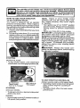
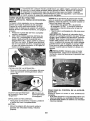
CLEANING
- Clean engine, battery, seat, finish, etc.
of all foreign matter.
• Clean debris from steering plate.
Debris can restrict clutch/brake pedal
shaft movement, causing belt slip and
loss of drive.
Nozzle
Washout Port
_, CAUTION: Avoid all pinch points and
movable parts
top side A /
,x_S
_.
_I_\ _\\ _ _"_ _,\\\\_
CAUTION:I
SteeringSystem, Dash,
A'_ Pinch]
Fenderand Mower_ot Shown _
Pointsl
•
Keep finished surfaces and wheels
free of all gasoline, oil, etc.
• Protect painted surfaces with automotive type wax.
We do not recommend using a garden hose
or pressure washer to clean your tractor
unless the engine and transmission are
covered to keep water out, Water in engine
or transmission will shorten the useful life of
your tractor, Use compressed air or a leaf
blower to remove grass, leaves and trash
from tractor and mower.
DECK WASHOUT PORT
Your tractor's deck is equipped with a
washout port on its surface as part of its
deck wash system. It should be utilized after each use,
1, Drive the tractor to a level, clear spot
on your lawn, near enough to a water
spigot for your garden hose to reach.
IMPORTANT: Make certain the tractor's
discharge chute is directed AWAY from your
house, garage, parked cars, etc, Remove
bagger chute or mulch cover if attached.
2, Make surethe attachment clutch control
is in the "DISENGAGED" position, set
the parking brake, and stop the engine.
3. Thread the nozzle adapter/packaged
with your tractor s Operator s Manual)
onto the end of your garden hose.
4. Pull back the lock collar of the nozzle
adapter and push the adapter onto the
deck washout port atthe left end of the
mower deck. Release the lock collar to
lock the adapter on the nozzle.
25
IMPORTANT: Tug hose ensuring connection is secure.
5. Turn the water on.
6. While sitting in the operator's position
on the tractor, re-start the engine and
place the throttle lever in the Fast ",_"
position.
IMPORTANT: Recheck the area making
certain the area is clear.
7. Move the tractor's attachment clutch
control to the "Engaged" position,
Remain in the operator's position
with the cutting deck engaged until the
deck is cleaned.
8. Move the tractor's attachment clutch
control to the "DISENGAGED" position. Turn the ignitionkey to the STOP
position to turn the tractor's engine off.
Turn the water off.
9. Pull back the lock collar of the nozzle
adapter to disconnect the adapter from
the nozzle washout port,
t0. Move the tractor to a dry area, preferably a concrete or paved area. Place
the attachment clutch control in the
"Engaged" position to remove excess
water and to help dry before putting the
tractor away,
_WARNING: A brokenor missingwashout
fitting couldexposeyou or othersto thrown
objectsfrom contactwith the blade.
• Replacebrokenor missingwashoutfitting
immediately,priorto usingmoweragain.
• Plug any holes in mower with bolts and
tocknuts.
,_
,,
4.
5.
6.
WARNING:
TO AVOIDSERIOUSINJURY,BEFOREPERFORMINGANY SERVICEOR
ADJUSTMENTS:
Depress
clutch/brake
pedal
fully and set parking
brake.
Place attachment
clutch
in "DISENGAGED"
position.
Turn ignition key to "STOP" and remove key.
Make sure the blades and all moving parts have completely stopped.
Disconnect spark plug wire from spark plug and place wire where it cannot come
in contact with plug.
TO REMOVE MOWER
1. Place attachment clutch in "DISENGAGED" position.
2, Lower attachment lift to lowest position.
3, Disengage belttension rod (K) from lock
bracket (L).
Ai_CAUTION: Rod is spring loaded. Have a
tight grip on rod and release slowly,
4. Remove mower belt from electric clutch
pulley (M)."
5, Disconnect front link (E) from mower remove retainer spring and washer,
6. Go to either side of mower and disconnect mower suspension arm (A) from
chassis and rear lift link (C) from rear
mower bracket (D) - remove retainer
springs and washers,
26
7. Go to otherside of mower and disconnect
the suspension arm and rear lift link.
_l_ CAUTION; After rear liftlinks are disconnected, the attachment liftlever will be spring
loaded, Have a tight grip on lift lever when
changing position of the lever,
8. From right side of mower, disconnect
anti-sway bar (S) from right rear mower
bracket (D) - remove retainer spring and
washer and pull mower toward you until
the bar falls from the hole in bracket.
9, Turn tractor steering wheel to the left as
far as it wig go.
10. Slide mower out from under right side of
tractor.
TO INSTALL MOWER
Follow procedure described in"TO INSTALL
MOWER" in the Assembly section of this
manual.
TO LEVEL MOWER
Make sure tires are properly inflated to the
PSI shown on tires, Iftires are over or under
inflated, it may affect the appearance ofyour
lawn and lead you to think the mower is not
adjusted properly.
VISUAL SIDE-TO-SIDE ADJUSTMENT
1. With all tires properlyinflated and if your
"lawn appears unevenly cut, determine
which side of mower is cutting lower.
NOTE: As desired, you can raise the low
side of mower or lower the high side,
2. Go to side of mower you wish to adjust,
3. With a 3/4" or adjustable wrench, turn
lift link adjustment nut (A) to the left to
lower the mower, or, to the right to raise
the mower.
;TurnnUt:righl
tO raise mower
4. If adjustment is necessary, see steps 2
and 3 in Visual Adjustment instructions
above.
5. Recheckmeasurements, adjustifnecessary until both sides are equal.
FRONT-TO-BACK ADJUSTMENT
IMPORTANT: Deck must be level sideto-side,
Toobtain the best cutting results, the mower
blades should be adjusted so the front tip is
t/8" to 1/2" lower than the rear tip when the
ower is in its highest position.
CAUTION: Blades are sharp. Protect
your hands with gloves and/or wrap blade
with heavy cloth.
• Raise mower to highest position.
• Position any blade so the tip is pointing
straight forward. Measure distance (B) to
the gro und at front and reartip ofthe blade,
• If front tip of blade is not 1/8" to 1/2" lower
than the rear tip, go to the front of tractor.
- With an 11/16" or adjustable wrench,
loosen jam nut A several turns to clear
adjustment nut B.
• With a 3/4" or adjustable wrench, turn
front link adjustment nut (B) clockwise
(Itighten) to raise the front of mower, or,
counterclockwise (loosen) to lower the
front mower.
Turn nut left
to lower mower
NOTE: Each full turn of adjustment nut will
change mower height about 3/16".
4. Test your adjustment by mowing some
uncut grass and visually checking the
appearance. Readjust, if necessary, until
you are satisfied with the results.
PRECISION SIDE-TO-SiDE ADJUSTMENT
1, With alltires properly inflated, parktractor
on level ground or driveway.
CAUTION: Blades are sharp. Protect
your hands with gloves and/or wrap blade
with heavy cloth,
2, Raise mower to its highest position.
3. At both sides of mower, position blade at
side and measure the distance (A) from
bottom edge of blade to the ground. The
distanceshould bethesameon bothsides.
Tightenadjustnut
B to raisemower
27
Loosen:adjust
nutB to !ower:
mower
Loosenjam nut A first
NOTE: Each full turn of the adjustment nut
willchange mower height about t/8".
• Recheck measurements, adjust if necessary until front tip of blade is 1/8" to 1/2"
lower than the rear tip.
• Hold adjustment nut in positionwifllwrench
and tighten jam nut securely against adjustment nut.
TO REPLACE MOWER DRIVE BELT
TO REPLACE MOTION DRIVE BELT
Park the tractor on level surface. Engage
parking brake. For assistance, there is a
belt installationguide decal on bottom side
of left footrest.
MOWER DRIVE BELT REMOVAL
1. Park tractor on a level surface. Engage
parking brake.
2. Lower attachment lift lever to its lowest
position.
3. Disengage belt tension rod (K) from lock
bCracket(L).
AUTION: Belttension rod isspring baded. Have afirm grip on rod and release slowly.
4. Remove screws (P) from R.H. and L.H.
mandrel covers and remove covers (Q).
5. Remove any dirtor grass clippings which
may have accumulated around mandrels
and entire upper deck surface.
6. Remove belt from electric clutch pulley
(M), both mandrel pulleys (R) and all idler
pulleys (S).
BELT REMOVAL 1. Remove mower (See "TO REMOVE
MOWER" in this section of manual).
NOTE: Observe entire motion drive belt and
position of all belt guides and keepers.
2. Remove beltfrom stationary idler (A) and
clutching idler (B).
3. Remove belt from centerspan idler (C).
4. Pull belt slack toward rear of tractor.
Carefully remove belt upwards from
transmission input pulley and over cooling fan blades (D).
5. Remove belt downward from engine
pulley (El.
6. Slide belt toward rear of tractor, off the
steering plate (F)and remove from tractor.
BELT INSTALLATION 1. Install new belt from tractor rear to front,
over the steering plate (F) and above
clutch brake pedal shaft (G).
2. Pull belt toward front of tractor and roll
belt onto engine putley (El.
3. Pull belt toward rear of tractor. Carefully
work belt down around transmission
cooling fan and onto the input pulley (D).
Be sure belt is inside the belt keeper.
4. Install belt on centerspan idler (C).
5. Install belt through stationary idler (A)
and clutching idler (B).
6. Make sure belt is in all pulley grooves
and inside all belt guides and keepers.
7. Install mower (See"TO INSTALL MOWER" in this section of manual).
MOWER DRIVE BELT INSTALLATION
1. Install belt around both mandrel pulleys
(R) and around idler pulleys (S)as shown.
2. Install belt onto electricclutch pulley (M).
IMPORTANT: Check belt for proper routing
in all mower pulley grooves.
3, Reassemble R,H. and L.H, mandre! covers (Q), Securely tighten all screws,
4, Engage belt tension rod (K) on locking
bracket (L),
;&CAUTION; Belt tension rod is spring loaded. Have atightgrip on rod andengages_owly.
5. Raise attachment lift lever to highest
position.
28
TO CHECK BRAKE
If tractor requires more than five (5) feet to
stop at highest speed in highest gear on a
level, dry concrete or paved surface, then
brake must be serviced.
You may also check brake by:
1+ Park tractor on a level, dry concrete or
paved surface, depress brake pedal all
theway down and engage parking brake.
2. Disengage transmission by placing
freewheel control in "transmission dis+
engaged" position. Pull freewheelcontroi
out and into the slot and release so it is
held in the disengaged position.
The rear wheels must iock and skid when
you try to manually push the tractor forward.
ff the rear wheels rotate, then the brake
needs to be serviced. Contact a Sears or
other qualified service center.
FRONT WHEEL TOE-IN/CAMBER
Your new tractor front wheel toe-in and camber is set at the factory and is normal. The
frontwheeitoe-in and camber are not adjustable. If damage has occurred to affect the
factory setfront whee!tee-(n or camber, contacta Sears or other qi+aatifiedservice center.
TO REMOVE WHEEL FOR REPAIRS
1, Block up axle securely.
2o Remove axle cover, retaining ring and
washers to allow wheel removal (rear
wheels have a square key - Do net lose).
3, Repair tire and reassemble.
NOTE: On rear wheels only: atign grooves in
rear wheel hub and axle. Insert square key.
4. Replace washers and snap retaining ring
securely in axle groove.
5. Replace axle cover.
NOTE: To seal tire punctures and prevent
flat tires due to s_ow leaks, purchase and
usetiresealant from Sears. TJresealantalso
prevents tire dry rot and corrosion.
Weak or Dead
Battery
Washers
Retaining
Ring \\
1
Axle Cover
TO START ENGINE WITH A WEAK BATTERY
,_,,WARNING: Lead-acid batteries generate explosive gases. Keep sparks, flame
and smoking materiars away from batteries.
Always wear eye protection when around
batteries.
If your battery istoo weakto startthe engine, it
should be recharged. (See "BATTERY" inthe
MAINTENANCE section of this manual).
If "jumper cables" are used for emergency
starting, follow this procedure:
IMPORTANT: Your tractor is equipped with
a 12 volt system+ The othervehicle must also
be a 12 volt system. Do not use yourtractor
battery to start other vehicles.
TO ATTACH JUMPER CABLES
1. Connect one end ofthe RED cable to the
POSITIVE (+) terminal of each battery(AB), taking care notre short againsttractor
chassis.
2. Connect one end of the BLACK cable
to the NEGATIVE (-) terminal (C) of fully
charged battery,
3. Connect the other end of the BLACK
cable (D) to good chassis ground, away
from fuel tank and battery.
TO REMOVE
CABLES,
REVERSE
ORDER
1. BLACK cable first from chassis and then
from the fully charged batter,].
2. RED cable last from both batteries.
_Square
Key (Rear
Wheel Only)
29
FullyCharged
Battery
REPLACING BATTERY
TO REMOVE HOOD AND GRILL ASSEMBLY
1. Raise hood.
2. Unsnap headlightwire connector.
3. Stand in front oftractor. Grasp hood at
sides, tilt toward engine and lift off of
tractor,
4. When replacing hood, be sure to reconnect the headlight wire connector.
_kWARNING: Do notshort battery'terminals
by allowing a wrench or any other object to
contact both terminals at the same time.
Before connecting battery, remove metal
bracelets, wristwatch bands, rings, etc.
Positive terminal must be connected first to
preventsparking from accidental grounding.
I. Lift hood to raised position.
2. Disconnect BLACK battery cable (A) then
RED battery cable and carefully remove
battery from tractor.
3. tnstalI new battery with terminals insame
position as old battery.
4. First connect RED battery cable (B) to
positive (+) batteryterminal with hex bolt
and keps nutas shown. Tighten securely.
Slide terminal cover ((3)over terminal,
5. Connect BLACKgrounding cable to negative (-) battery terminal with remaining
hex bolt and keps nut. Tighten securely.
6. Close hood.
Negative
(Black)
Cab[e
TRANSMISSION
REMOVAL/REPLACEMENT
Shouldyourtransmission requireremovalfor
sewice or replacement, itshould be purged
after reinstallationand before operating the
tractor. See "PURGE TRANSMISSION" in
the Operation section of this manual.
Positive
(Red)
Cable
TO REPLACE HEADLIGHT BULB
1. Raise hood,
2. Remove bulb holderfrom the hole in the
backside of the grill.
3. Replace bulb in holder and install bulb
holder securely back into the hole in the
backside of the grill.
4. Close hood.
INTERLOCKS AND RELAYS
Loose or damaged wiring may cause your
tractor to run poorly, stop running, or prevent
it from starting.
• Check wiring.
TO REPLACE FUSE
Replace with 30 amp automotive-type plugin fuse. The fuse holder is located behind
the dash.
ENGINE
TO ADJUST THROTTLE CONTROL
CABLE
The throttle control has been preset at
the factory and adjustment should not be
necessary Check adjustment as described
below before loosening cable. If adjustment
is necessary, see engine manual,
TO ADJUST CHOKE CONTROL
The choke control has been preset at
the factory and adjustment should not be
necessary. If adjustment is necessary, see
engine manual.
TO ADJUST CARBURETOR
Your carburetor has been preset at the factory
and adjustment should not be necessary.
However, minoradjustment maybe required
to compensate for differences in fuel, temperature, altitude or load. If the engine does
need adjustment, see engine manual.
3O
Immediately prepareyour tractorforstorage
at the end of the season or if the tractor will
not be used for 30 days or more.
_WARNING:
Never store the tractor with
gasoline in the tank inside a building where
fumes may reach an open flame or spark,
Allow the engine to cool before storing in
any enclosure.
TRACTOR
Remove mower from tractor for winter
storage, When mower is to be stored for a
period of time, clean it thoroughly, remove
all dirt, grease, leaves, etc. Store in a clean,
dry area.
t. Clean entire tractor (See "CLEANING"
in the Maintenance section of this
manual),
2. Inspect and replace baits, if necessary
(See belt replacement instructions in the
Service and Adjustments section of this
manual).
3. Lubricate as shown in the Maintenance
section of this manual.
4. Be sure that all nuts, bolts and screws
are securely fastened, Inspect moving
parts for damage, breakage and wear.
Replace if necessary.
5. Touch up all rusted or chipped paint
surfaces; sand lightly before painting.
BATTERY
• Fully charge the battery for storage.
• After a period of time in storage, battery
may require recharging.
• To help prevent corrosion and power leakage during long periods of storage, battery
cables should be disconnected and battery cleaned thoroughly (see "TO CLEAN
BATTERY AND TERMINALS" in the
Maintenance section of this manual).
- Aftercleaning, leavecables disconnected
and place cables where they can not come
in contact with battery terminals.
• If battery is removed from tractor for
storage, do not store battery directly on
concrete or damp surfaces.
31
ENGINE
FUEL SYSTEM
IMPORTANT: It is important to prevent
gum deposits from forming in essential fuel
system parts such as carburetor, fuel hose,
or tank during storage. Also, alcohol blended
fuels (called gasohol or using ethanol or
methanol) can attract moisture which leads
to separation and formation of acids during
storage. Acidic gas can damage the fuel
system of an engine while in storage.
• Empty the fuel tank by starting the engine
and letting it run until the fuel lines and
carburetor are empty.
• Never use engine or carburetor cleaner
products in the fuel tank or permanent
damage may occur.
- Use fresh fuel next season.
NOTE: Fuel stabilizer is an acceptable al.
temative in minimizing the formation of fuel
gum deposits during storage. Add stabilizer
to gasoline in fuel tank or storage container.
Always followthe mix ratio found on stabilizer
container. Run engine at least 10 minutes
after adding stabilizer to allow the stabilizerto
reach the carburetor. Do not empty the gas
tank and carburetor if using fuel stabilizer.
ENGINE OIL
Drain oil (with engine warm) and replace
with clean engine oil. (See "ENGINE" in the
Maintenance section of this manual).
CYLINDER(S)
1. Remove spark plug(s)_
2. Pour one ounce of oil through spark plug
hole(s) into cylinder(s).
3. Turn ignition keyto "START" position for
a few seconds to distribute oil.
4. Replace with new spark plug(s).
OTHER
• Do not store gasoline from one season to
another,
• Replaceyour gasoline can ifyour can starts
to rust, Rust and/or dirt in your gasoline
will cause problems.
° If possible, store your tractor indoors and
cover itto give protection from dustand dirt.
- Cover your tractor with a suitable protective cover that does not retain moisture.
Do not use plastic. Plastic cannot breathe
which allows condensation toform and will
cause your tractor to rust.
IMPORTANT:
Never cover tractor while
engine and exhaust areas are still warm.
TROUBLESHOOTING CHART:
See appropriate section in manual unless directed to Sears service center
PROBLEM
Will not start
1
Out of fuel
1
Fill fuel tank,
2
Engine not "CHOKED"
2
See "TO START ENGINE" in
Operation section.
Engine flooded.
3
Wait severat minutes before
attempting to start,
4
Bad spark plug,
4
Replace spark plug.
5
Dirty air filter,
5
Clean/replace
6
Dirty fuel filter,
6 i Replace fuel filter,
7
Water in fuel.
7
Empty fuel tank and carburetor,
refill tank with fresh gasoline and
replace fuel filter.
8
Loose or damaged wiring.
8
Check all wiring,
9
Carburetor
9
See "To Adjust Carburetor" in
Service and Adjustments section.
10
Contact a Sears or other qualified
service center,
10
Hard to start
CORRECTION
CAUSE
properly.
out of adjustment,
Engine valves out of adjustment,
air filter,
1
Dirty air filter.
1
Clean!replace
2
Bad spark plug,
2
Replace spark plug.
Weak or dead battery.
3
Recharge or replace battery.
4
Dirty fuel filter.
4
Replace fuel filter.
5
Stale or dirty fuel,
5
Empty fuel tank and refill tank with
fresh, c]ean gasoline.
6
Loose or damaged wiring.
6
Check all wiring,
7
Carburetor out of adjustment.
7
See "To Adiust Carburetor" in
Service and Adjustments section.
8
Engine valves out of adjustment.
8
Contact a Sears or other qualified
service center.
1
Brake pedal not depressed.
1
Depress brake pedal,
2
Attachment
2
Disengage
3
Weak or dead battery,
3
Recharge or replace battery,
4
Blown fuse.
4
Replace fuse.
5
Corroded battery terminals.
5
Clean battery terminals.
6
Loose or damaged wiring,
6
Check all wiring,
7
Faulty ignition sWitch.
7
Check/replace
ignition switch,
8
Faulty solenoid or starter.
8
Check/replace
solenoid or starter.
9
Faulty operator presence
switch(us).
9
Contact a Sears or other qualified
service center,
i 3
a!r filter,
........
,,,,,,,,,,,,,,,,,,,,,,,
,, ,, ,,, ,,,,, .......
Engine will not
turn over
clutch is engaged,
32
attachment
clutch,
TROUBLESHOOTING CHART:
See appropriate section in manual unless directed to Sears service center
PROBLEM
CORRECTION
Engine clicks but
will not start
1
Weak or dead battery,
i
Recharge or replace battery,
2
Corroded battery terminals.
2
Clean battery terminals.
3
Loose or damaged widng.
3
Check eli wiring.
4
Faulty solenoid or starter.
1
Cutting too much grass!too
2
Throttle in "CHOKE"
3
4
Dirty air filter.
5
Low oil leveUdirty oiL
6
Faulty spark plug.
4
..................
,,,,,,,,,
,,
Loss 'of power
7
CheckJreplace solenoid or starter.
..........
u,,,,,,,,
,,
fast.
1
Raise cutting height/reduce
speed.
position.
2
Adjust throttle control.
Build-up of grass, leaves and
trash under mower.
3
Clean underside of mower
housing.
4
Clean/replace
5
Check oil tevefJchange oil,
_6
air filter,
Clean and regap or change spark
plug.
Dirty fuel filter.
7
Replace fuel filter.
Stale or dirty fuel.
8
Empty fuel tank and refill tank witl
fresh, clean gasoline,
Water in fuel.
9 I Empty fuel tank and carburetor,
refiit tank with fresh gasoline and
replace fueJ filter.
10
Spark plug wire loose.
10 Connect and tighten spark plug
wire,
11
Dirty engine air screen/fine.
11 Clean engine air screen/fins.
12
Dirtylclogged
12
Clean/repiace
13
Loose ordamaged
13
Check all wiring,
14
Carburetor
15
Engine valves out of adjustment.
!8
9
mLrfflen
widng.
out of adjustment.
muffler.
14 ;See "To Adjust Carburetor" in
Service and Adjustments section,
15
Contact a Sears or other qualified
service center.
,,,,,,,
Excessive
vibration
1
Worn, bent or loose blade.
1
Replace blade, Tighten blade bolt
2
Bent blade mandrel.
2
Contact a Sears or other
Loose/damaged
3
qualified service center.
,
Engine
continues
run when operator
leaves
seat with
attachment
clutch
to ""1
part(s).
Tighten loose part(s).
Replace damaged parts.
1,,,,
Faulty operator-safety
control system.
engaged
33
presence
1
Check wiring, switches and
connections. If not corrected,
contact a Sears or other
TROUBLESHOOTING CHART:
See appropriate section in manual unless directed to Sears service center
PROBLEM
Poor
cut
CAUSE
- uneven
!
Worn, bent or loose blade.
1
Replace blade. Tighten b_ade bol
2
Mower deck not level,
2
Level mower deck.
3
Buildup of grass, leaves, and
trash under mower.
3
Clean underside
housing.
4
Bent blade mandrel.
4
Contact a Sears or other
qualified service center.
5
Clogged mower deck vent from
build-up of grass, leaves, and
trash around mandrels.
5
Clean around mandrels to
open vent holes.
t
Obstruction
1 ' Remove obstruction.
2
Worn/damaged
3
Frozen idler pulley.
3
Replace idler pulley,
4
Frozen blade mandrel,
4
Contact a Sears or other qualified
service center.
Engine speed too slow.
1
Place throttle control in "FAST"
)osition.
2
Travel speed too fast.
2
Shiftio
3
Wet grass,
3
Allow grass to dry before mowing.
4
Mower deck not level.
4
Level mower deck.
5
Low/uneven
5
Check tires for proper PSL
6
Worn, bent or loose blade.
6
Replace/sharpen
blade bolt.
Buildup of grass, leaves and
trash under mower.
7
Clean underside of mower
housing,
8
Mower drive belt worn.
8
Replace mower drive belt,
9
Blades improperly installed.
9
ReinstalI blades sharp edge down
cutting
Mower blades will
not
rotate
"OORRECTI()N
Poor grass
discharge
in clutch mechanism.
mower
drive belt. 2
tire air pressure.
10
of mower
Replace mower drive belt.
slower speed.
blade. Tighten
10
Improper blades used.
Replace with blades listed in
this manual
11
Clogged mower deck vent holes
11
from buildup of grass, leaves, and
trash around mandrels,
Clean around mandrels to
open vent holes.
....u,,J,,,
,,
Headlight(s)
working
not
1
Ught switch is "OFF".
1
Turn light switch "ON".
(if so equipped)
2
Bulb(s) or lamp(s)
2
Replace bulb(s) or lamp(s).
3
Faulty light switch.
3
Checkireplace
4
Loose or damaged wiring.
4
Check wiring and connections,
5
Blown fuse.
5
Replace fuse.
burned out.
J ,
34
light switch.
TROUBLESHOOTING CHART:
See appropriate section in manual unless directed to Sears service center
PROBLEM
....
CORRECTION
CAUSE
,,,,,,,,,,,,,,,,
Battery Wlll
not
charge
1
'Bad battery ceil(s).'
.........................
1" ' Replace battery.
2
Poor cable connections.
2
Check/clean
3
Faulty regulator
3
Replace regulator.
4
Faulty alternator.
(if so equipped).
,,,,,
Loss
of drive
"OFF"
Replace alternator,
Place fraewhee] control in
"engaged" posit{on.
...............
Freewheel control in "disengaged"
posit{on,
2
Motion drive belt worn, damaged
or broken.
2
Replace motion drive belt.
3
Air trapped in transmission
shipment or servicing.
3
Purge transmission.
during
,
Engine throttle
control not set 1
between half and full speed (fast)l
position before stopping engine.
';""'"Reve=e
operation
sy,tem('ROSl1
!Engine
dies when
tractor
is shifted
into reverse
,,_,,,,,,
1
1
1
engine
4
..................
u,,,,
......
,,,,
when turning
all connections.
is not "ON" while mower or other
attachment is engaged.
......
,,,,,,,,,,
Move throttle control between
half and full speed (fast) position
before stopping engine.
Turn ignition key to ROB "ON"
position. See Operation section.
You [[ find the answer and more on managemyhome.cem
- for free!
- Find this and a[_your other product manuals online.
i " Get answers from our team of home experts.
• Get a personalized
• Find information
maintenance
and tools
plan for your
to help with
home.
home projects.
manage i h°me
i
brought to _u _aySears
.!
35
Z
0
I-ILl
o,,,
/
0
/
tu
!
/
nO
!
/
LL
_0
I
z
o
13.
0
.J
i
--r
nO
r_
/
(D
r_
W
/
/
I
€O
/
!
/
36
Garantfa ..........................................................
Reglas de Seguridad ......................................
Especificaciones del Producto ........................
Montaje!Pre Operaci6n ...................................
Operaci6n .......................................................
Mantenimiento ................................................
37
38
41
42
48
56
Programa de Mantenimiento.................... ......56
Servicio y Ajustes ........................................... 61
Alrnacenarniento ............................................. 66
tdentificaci6n de Problemas ........................... 67
Servicio Sears .................................. Contratapa
Garantia papa equipos tractores Craftsman
GARANTiA COMPLETA DE CRAFTSMAN
PeR DOS AI_OS desde ra fecha de compra, todas Ias partes no sustituibles de este equipo tractor estdn
garantizadas
contra cualquier defecto de material o mane de obra. Una parte no sustituible defectuosa
recibir_ reparaci6n o reemplazo gratuito encasa si la reparaciSn es imposible.
PeR CINCO ANO$ desde la fecha de compra, el bastidor y el eje detantero de este equipo tractor estdn
garantizados contra cuatquier defecto de material o mane de obra, Un bastidor o eje derantero defectuoso
recibir_ reparaci6n o reemplazo gratuito encasa si la reparaci6n es imposible.
DURANTIE 90 DiAS desde la fecha de compra, la bateria (una parts sustituible) de este equipo tractor
est& garantizada contra cualquier defecto de material o mane de obra (nuestra prueba comprueba que no
contendr& carga). Una bateria defectuosa recibir,'_ un reemprazo gratuito encasa.
GARANTIA
LIMtTADA DE PeR VIDA ADICIONAL en el EJE DELANTERO
DE HIERRO COLADO (s|
est_ provisto)
DURANTE EL TIEMPO EN QUE SE USE per el propietario original despuds del quinto aSo a partir de.la
fecha de compra, el eje deJantero de hierro cofado (si estd provisto) de este equipo tractos estd gerantizado
centre cualquier defecto de material o mane de obra. Con el comprobante de compra, un eje delantero de
hierro cofado recibir& un reemplazo gratuffo en case.
SERVICIO
DE GARANTiA
Pare conocer los detalles de Ia cobertura de garanfia pare obtener una reparaci6n
llame al 1-800-659_5917 6 visits el sitio web: ,_,vw. craftsman,corn
o reempfazo
gratuito,
En todos los cases anteriores, si el reempiazo es imposible, el equipo tractor ser_ sustituido sin cargo con
ef mismo modelo o uno equivalente.
Toda la cobertura de garantfa anterior ser_ nuia si este equipo tractor ee utiliza alguna vez para bdndar
servicios comerciales o si se alquila a otra persona.
Esta garantfa cubre 0NICAMENTEdefectosde
materialymano
de obra, Lacoberturade garantia NO incluye:
• Partes sustituib]es (excepto la baterfa) que se puedan desgastar per el use normal dentro del periodo de
garantia incfuso, pero sin limitarse a, cuchillas, buj|as, ffltros de airs, corTeas y fiitroe de aceite.
• ServicJos de mantenimiento estdndar, oambios de aceite o afinaciones.
• Reemplazo o reparaci6n de neumdtJcos per pinchazos causeries per objetos externos come clavos,
espinas, tocones o vidr'ios.
• Reemplazo o reparaci6n de neumdticos o ruedas per desgaste normal, accidentes o per operaci6n o
mantenimiento
incorractos,
• Reparaciones necesarias per abuse del operador incluso, pero sin limitarse a, daSos causados per
remolcar objetos que superen la capaciclad del equipo tractor, chocar centre objetos que doblen el
bastidor, el ensemble del eje o el cig_3eSalo sobrepasar la velocidad del motor.
• Reparaciones necesarias per negligencia del operador, incluso (pero sin limitarse a e]lo) daSos eldctricos
y mec_nicos causados per e] aimacenamiento incorrecto, per no usar el grade y la cantidad corrs_os de
aceite de motor, per no mantener del muelte libre de residues inflamables opo[ no mantener el equipo
tractor de acuerdo con Ias instrucciones que contiene el manual del operador.
• Limpieza o reparaciones
del motor (sistema de combustibte)
cuando se determina que se usd
combustible contaminado y oxidado (sarro). En general, el combustible debe usarse dentro de los ,30
d_as posteriores a su compra.
• Deterioro y desgaste normal de los acabados extedores o sustitucJSn de r6tulos de productos.
Esta garant_a le otorga derechos legates especfficos, y usted tambi_n puede tenet otros derechos que
vadan de un estado a otro.
Sears Brands
Management
Corporation,
Hoffman
37
Estates,
IL 60179
IMPORTANTE: Esta Maquina cortadora es capaz de amputar las manosy los pies y de Ianzar objetos, si
no se observan tas instrucciones de seguridad siguientes se pueden producir lesiones graves o la muerte,
I. FUNCIONAM|ENTO
GENERAL
• Nohacerfuncionarlam&quinasinelcaptador
de hierba entera, la protecci6n de descarga u
A_ILADVERTENCIA: Siempre desconecte el
otros dispositivos de seguridad en su lugar y
alambre de la bujfa y p6ngalo donde no pueda
en buenas condiciones.
entrar en contacto con la bujia, para evitar el
• Ralentizar antes de girar,
arranque per accidente, durante la preparaci6n,
- Nunca dejar una m__quinaencendida sin vigiel transporte, el ajuste o cuando se hacen
Iancia, Apagar siempre las cuchiJlas, porter el
reparaciones.
freno de estacionamiento, parar el motor, y
_I_DVERTENOIA:
No avance cuesta abajo a
quitar las Ilaves antes de bajar.
punto muerto ya que podria perder el control
• Desconectar las cuchillas cuando no se corta.
del tractor.
Apagar el motor y esperar que todas Ias partes
est_n completamente paradas antes de limpiar
_iADVERTENOIA:
Remolque sotamente los
la m&quina, quitar el captador de hierba, o
accesodos recomendados y conformes a las
desatascar la protecci6n de descarga,
caracteristicas indicadas per et fabricante de
• Hacer funcionar la m_.quina s61ocon ]a Iuz deI
su tractor. Tenga cuidado y prudencia al utilizar
dia o luz artificial buena.
et tractor. Cuando se encuentre en un declive,
oper utilJzando exclusivamente la velocidad m_.s • No hacer funcionar la m&quina estando bajo
los efectos de alcohol o droga,
baja, En case de un declive una carga excesiva
• Poner atenci6n altr&fico cuando se opera cerca
podrfaresultar peligrosa. Los neum&ticos pueden
de calles o se cruzan.
perder Ia tracci6n con el suelo y hacede perder
• Poner la m_Lximaatenci6n al cargar o descarel control de su tractor.
gar Ia m_quina en una caravana o cami6n.
_.DVERTEENOIA:
El tube de escape del motor,
- Llevar siempre galas de protecci6n cuando se
algunos de sus constituyentes y algunos eom_
hace funcionar la m&quina.
ponentes deI vehiculo contienen o desprenden
• Los dates indican que los operadores a partir
productos quimicos conocidos en el Estado de
de los 60 a5os est&n afectados per un gran
California come causa de c&ncer y defectos al
porcentaje de heridas relativasa Ia conducci6n
nacimiento u otros da_os reproductivos.
del cortac6sped. Estos operadores tendrian
_DVERTENCIA:
Los bornes, terminales y
que eva]uar su habilidad de hacer funcionar
accesorios relatives de ta baterfa contienen plomo
el cortac_sped de mode Io bastante seguro
o compuestos de plomo, productos qulmicos
para proteger a si mismos y a otras personas
conocidos en el Estado de California come causa
de heridas graves.
de c&ncer y defectos al nacimiento u otros dahos
• Seguir Ias recomendaciones del fabricante
reproductivos. Lavar las manes despu@s de
para los pesos y contrapesos de las ruedas.
manipularlos.
• Mantener ta m&quina libre de hierba, hojas
u otros escombros que pueden tocar el
• Leer,entender y seguir todas las instrucciones
tube de escape / partes del motor calientes
sobre la m&quina yen el manual antes de
y quemarse. No permitir que el puente deI
empezar.
cortac_sped cargue hojas u otros residues
• No poner las manes o los pies cerca de partes
que pueden causar acumulaciones, Umpiar
giratorias o debajo de la m_.quina, mantener
toda salpicadura de aceite o earburante antes
siempre limpia la abertura de descarga,
de hacer operaciones sobre Ia mAquina o
° Permitir el funcionamiento de la m_.quina s6[o a
guardarla, Dejarla enfriar antes de guardarla.
adultos que tengan familiaridad con las instrucclones.
• Limpiar el &rea de objetos come piedt'as,
II, FUNCIONAMIENTO
EN PENDIENTES
juguetes, cables, etc, que pueden ser recogiLas pendientes son el mayor factor de accidos y disparados con las cuchillas,
dentes relativos a la perdida de control y vuelco,
• Asegurarse de que el &rea est_ libre de otras
que pueden causar severas heridas o muerte.
personas antes de ponerta en marcha. Parar
El func]onamiento en pendientes requiere una
la m&quina si alguien entra en el _.rea,
atenciSn extra. Si no es posible hacer marcha
• Nunca Ilevar pasajeros.
atr_.s en una pendiente o si te sientes incomodo,
• No cortar marcha atr&s al no set absolutamente
no la cortes,
necesario. Mirar siempre abajo y detante mien• Cortar hacia arriba y abajo de una pendiente,
tras se precede atr&s.
no de mode horizontal,
• Nunca dirigir el material descargado haoia
• Porter atenciones a Ios hoyos, las ralces, los
nadie, Evitar descargar material contra paredes
buttes, Ias piedras u otros objetos escondidos.
u obstrucciones. El material podda rebotar
El terreno irregular puede volcar la m&quina,
hacia el operador, Parar las cuchillas cuando
La hierba alta puede esconder obst_cuJos,
se pasan superficies de grava.
38
• Escoger una velocidad de rnarcha baja de
rnodo que no sea necesario pararse o cambiar
estando en una pendiente.
, No cortar la hierba mojada. Las ruedas pueden
perder traccibn.
Poner siempre una rnarcha cuando se est&
en pendientes. No poner en punto muerto e ir
cuesta abajo.
• Evitar arrancar, pararse o girar en una pendiente. Si las ruedas pierden tracci6n, desconectar tas cuchitlas y proceder despacio cuesta
abajo en la pendiente.
• Mantener todo los movirnientos en Ias pendientes tentos y gradual. No hacer carnbios
repentinos de velocidad o direcci6n, ya que
pueden causar el escape de la rn_.quina.
• Poner la m_odma atenci6n cuando la rn&quina
funciona con captadores de hierba u otros
dJspositivos enganchados; pueden afectar la
estabiiidad de ta rn&quina. No usar en pendientes ernpinados.
• No intentar estabilizar [a m&quina poniendo el
pie en el terreno.
• No cortar cerca de bajadas, cunetas y odllas.
Las rn&quina puede volcarse irnprovisamente
si una rueda est& en el borde o se hunde.
i11. NI1;|OS
Si eJoperador no pone atenci6n a la presencia
de los niSos pueden ocurrir accidentes trdgJcos.
Los niSos a menudo est_n atraldos por ia m&quinay tas actividad de cortac No dar por hecho
de que los nitros se queden adonde estaban la
drtima vez que los vistes.
• Mantener los nitros fuera del &tea de corte y
vigilados por un adulto responsabie que no sea
el operador.
• Estar alerta y apagar la rn_quina si un niSos
entra en et &rea.
, Antes y durante la marcha atrds, mirar adelante
y abajo para vet si hay niSos pequeSos.
, Nunca Ilevar nifios, inclusosi hay las cuchillas
apagadas. Podrfan caer y herirse seriamente
o interferir con el funcionamiento seguro de ta
rn&quina, los niSos que se ban Ilevado prem
edentemente pueden aparecer de pronto en el
drea de corte pot otto paseo y ser atropellados
o tumbados por la rn&quina.
• Nunca dejar que los niSos manipulen la
m&quina.
- Tener el rn_irno cuidado cuando se acerca
a cantos ciegos, arbustos, _rboles u otros
objetos que pueden impedir Javista de ni_os.
IV. REMOLQUE
• Remolcar s61ocon una rn_quina que tenga un
gancho disefado para remolcar. Enganchar el
equipo o remolcar s01oen el punto dispuesto
al efecto.
, Seguirlasrecornendacioneedelproductorcon
respecto a los llrnites del equipo pot rernolcar
y el rernolque en pendientes.
3g
• Nunca permitir que ni_os u otras personas
est_n dentro de] equipo por remolcar.
° En pendientes, el peso del equipo rernolcado
puede causar la p_rdida de tracci6n y la pdrdida de control.
• Viajar despacio y dejar rn_.s distancia para
frenar.
V. SERVICIO
MANIPULACION
SEGURA DE LA
GASOLINA
Para evitar heridas personales o dafios alas
cosas, poner el rn_tximo cuidado a la hora de manJpular la gasolina. La gasolina es extrernamente
inflamable y los vapores son explosivos.
• Apagar todos los cigarrrllos,cigarros, pipas y
otras fuentes de ignici6n.
• Usar s61ocontenedores para gasolina aprobados.
• Nunca quitar el tap6n de ragasolina o afiadir
carburante con el motor en rnarcha, dejar
enfriar el motor antes del abastecirniento de
Ia gasolina.
• Nunca abastecer la rndquina al interior de un
local,
• Nunca guardar ]a mdquina o e] contenedor
deI carburante donde haya una llama abierta,
chispas o una luz piloto corno un carentador
de agua u otros dispositivos.
• Nunca Irenar los contenedores at interior de
un vehiculo o en una caravana o carni6n
recubiertos con un forro de pI&stico. Colocar
siempre los contenedores en el terreno tejos
del vehfculo cuando se est_ Jlenando.
• Quitar el equipo de gas del cami6n o caravana
y abastecerlo en el terreno. Si no es posible,
abastecer dicho equipo con un contenedor
port&til, m&s bien que de un surtidor de gasotina.
• Mantener la boquilla a contacto del borde
del dep6sito de carburante o la abertura deI
contenedor durante toda la operaci6n de
abastecimiento. No utilizar un dispositivo con
boquiUa cerrada-abierta.
• Si se vierte carburante sobre la ropa, carnbiarse ta ropa inmediatamente.
• Nunca lienar el dep6sJto rn&s de Io debido.
Volver a colocar el tap6n del gas y cerrar de
modo firrne.
OPERACIONES
GENERALES
DE SERVIClO
- Nunca hacer funcionar la mdquina en un drea
cerrada,
• Mantenertodaslastuercasypernosapretados
para asegurarse de quetrabaja en condiciones
seguras.
• Nunca modificar ros dispositivos de seguridad.
Controlar su correctofuncionamiento regularrnente.
• Mantener
Eam&quina
[ibre de
hierba, hojas
u otros residues acumuladoso Limpiar Ias
salpicaduras de aceite o carburante y quitar
cualquier cosa mojada con carburante. Dejar
que la m&quina se enfrle antes de guardada.
• Si se golpea un objeto ajeno, hay que pararse
e inspeccionar Ia mQquina. Reparar, si es necesario, antes de velvet a porter en marcha.
• Nunca hacer ning0n ajuste o reparaci6n con
el motor en funci6n.
• Controlar los componentes del captador de
hierba y la protecci6n de Ia descarga frecuentemente y sustituir con partes recomendadas
per el fabdcante, en su case.
- Las cuchi]las del cortac_sped son afiladas.
Envolver la cuchilla, ponerse guantes y porter
Ia m,_ima atenciSn cuando se hacen operaciones en elias.
• ControJar eI funcionamiento deJfreno frecuentemente. Ajustar y hacer las operaciones de
mantenimiento cuando eso sea necesario.
• Mantener y sustituir las etiquetas de seguridad
e instruccibn, cuando sea necesario.
@@@@@
- Asegurarse de que el &rea est_ libre de otras
personas antes de ponerla en marcha, para la
m&quina si alguien entra en el &tea.
. Nunca Ilevar pasajeros.
• No cortar marcha atr_s al no ser absolutarnente
necesario. Mirar siempre abajo y delante mientras se precede atr&s.
• Nunca llevar nifios, incluso si hay las cuchillas
apagadas. Podrian caer y herirse seriamente
o interferircon el funcionamiento seguro de la
m&quina, los niSos que se ban llevado precedentemente pueden aparecer de pronto en el
_.rea de corte per otto paseo y set atropellados
o tumbados per la m_.quina.
• Mantener los nifios fuera del _ea de corte y
vigilados per un adulto responsable que no sea
el operador.
° Estar alerta y apagar la m,_quina si un nifios
entra en el &tea.
40
• Antes y durante la rnarcha atr_.s, mirar adelante y abajo para ver si hay niSos pequehos.
• Cortar hacia arriba y abajo de una pendiente
(t5 ° M_'_), no de mode horizontal
• Escoger una velocidad de marcha baja de
mode que no sea necesario pararse o cambiar estando en una pendiente.
- Evitar arrancar, pararse o girar en una
pendiente. Si las ruedas pierden tracci6n,
desconectar las cuchillas y preceder despacio cuesta abajo en ta pendiente.
• Si la m&quina se para mientras va cuesta
arriba, desconectar Ias euchillas, porter la
marcha atr&s y ir hacia atr&s despacio.
° No girar estando en pendientes si no es necesario, y luego girar despacio y gradualmente
cuesta abajo, si es posibie.
ESPECIFICACIONES
DEL PRODUCTO
En el estado de California, le tey exige Io anterior
(Secci6n 4442 del "California Public Resources
Gode"). Otros estados pueden center con otras
leyesparecidas. Lasleyesfederales se aplican en
iatierrasfederales.Su centre de Serviciorobs cercane tiene disponibleamortiguadores de chispas
pera e! siienciador. (Vea Ia secci6n de Partes de
Repuesto en el manual Ingles del duer3o.)
Capaoidad y Tipo 3,0 Galones (11,35 L)
de gasoline:
Regular Sin Plomo
1ipo de Aceite:
(API-SG-SL)
SAE 30 (Sobre 32°F I 0°C)
SAE 5W30
(Debajo 32°F/0°C)
Capacidad de
Aceite:
Con filtro: 64 oz.(1,9 L)
Sin filtro: 60 oz.(1,7 L)
Bujia:
Champion QC12YC
(Abertura: .040"/1,02ram)
Velocidad de
Delante:
Recorrido (MPH): Marcha Atr&s:
5,2 - 8,4
2,9 - 4,7
Sistema de Carge: 16 Ampe @ 3600RPM
Baterfa:
AmpiHr:
28
Min. QCA:
230
Case Size:
UI R
Torsi6n del Perno
de la Cuchitla:
45-55 Ft. Lbs. (62-75 Nm)
FELICITACIONES per la compra de su tractor.
Ha side disedado, ptanificado y fabricado pare
darle la meier confiabilidad yet mejor rondimiento
posibte.
En eI case de que se encuentre con cualquier
problema que no pueda solucionar f&cilmente,
hage el favor de ponerse en contacto con un
centre do servicio Sears o con un otro centre de
servicio cualificado. Ouenta con representantes
bien capacitados y cempetentes y con las herramientas adecuadas pare dade ser¢icio o pare
reparar este tractor,
Haga eWfavor de leer y de guarder este manual.
Estas instrumc(ones le permitir_n mental" y mantener su unided en forma adecuada. Siempre
observe las "REGLAS DE SEGURIDAD,"
ACUERDO DE REPUESTO
Este productoincluye un Acuerdo de Repuest0.
P6ngase en contacto con su tienda Sears m&s
cercana pare informarse sobre los detelles.
RESPONSABILIDADES
DEL CLIENTE
* Lea y observe las reglas de seguridad.
- Siga un programa regular de mantenimiento,
ouidado y use de su tractor.
. Siga Ias instrucciones descdtas en tas secciones "Mantenimiento ° y '_,lmacenamiento"
de este Manual del Dueffo.
_I_DVERTENCIA:
Este tractor viene equipedo
con un motor de combusti6n interne y no se debe
user sobre, ocerca, de unterreno no desazrollado
cubierto de bosques,
de arbustos o de c_sped, o menos que el sistema
de escape del motor venga equipado con un
amortiguador de chispas que cumpla con las
leyes locales o estataJes (si existen). Si se use un
amortiguador de chispas, el operador debe mentenerlo en condiciones de trabajo eflcientes.
41
ACUERDOS
DE PROTECClON
PARA
LA REPARACION
Congratulaciones per su buena compra.
Su nuevo producto Craftsman® estd diseSado
y fabricado para funcionar de mode _able pot
touches aSos, Pete cornotodos los productos,
puode necesitar alguna reparaci6n de tanto
en lento. En este case tener un Acuerdo de
Protecoi6n pare JaReparacibn puede haoerles
ahorrar dinero y fastidios.
Compre chore un Acuordo de Proteccf6n pare
la Reparaci6n y prot_.gesede molestias y gastos
inesperados.
Un Acuerdo incluye los puntos siguientes:
• Servicio experto de nuestros 12.000 especialistas profosionales en la reparaciSn.
. Servicio ilimitado sin cargo alguno pare
Ias partes y la mane de obra sobre todas las
reparaciones garantizades.
• Sustituci_n del producto si su producto
garantizado no puede ser erreglado.
• Descuento de! 10% sobre el precio corriente
detservicio y fie las pertes relativas al servicio
no cubiertas per el acuerdo; tambi_n el t0%
menos sobro el precio ¢orriente de un control
de mantenimiento preventive.
• Ayuda r_plda per tel_fono - soporte telefbnico per parte de un representante Sears sobre
productosque requieren un arreglo en case, y
adem&s una programaoi6n sobro los arreglos
mAs convenientes.
Cuando se ha comprado el Acuerdo, baste con
una Ilamada tefefbnica pare programaref servicio.
Puede lJamar cuando quiera, die y noche o
tijar en I{nea una cita para obtener el servicio.
Sears tlene m&s de 12.000 especialistas
profesionalesen Ia reparaci6n, que tienen
acceso a m_.s de 4.5 railleries de partes y
accesorios de celidad.
Este es eltipo de profesionalidad con que puede
contar pare ayuder a alarger la vide de! producto que acaba de comprar, per touches aSos.
iCompre hey su Acuerdo de Proteccibn pare la
Reparacibn]
Se aplioan algunas limitaciones
y ex¢luslones. Para conocer los precios y tenet m_s
lnforma¢ibn_ Ilame al 1-800-827-6655.
SERVICIO DE INSTALAC|ON
SEARS
Pare ta tnstalaci&n profesional Seam de aparatos
de casa, puertas de garaje, calentadores de ague
y otros import_ntes
articu]os pare la casa, en U.S,A flamar a
1.800-4-M¥-HOME®
J
1
Segadora
(_
Rueda Delantera De La Segadora
(2) Con junto
(5) 1_3/16"
Arandela
_'_
(1) Perno
de levantamiento
de eslabones
traseros
(_) 1-1/4"
Arandela
(1! Abrazadera
pequefio
de retenci6n
_\
\\
(1) Eslabones
"_,.,
de levantamiento
_.
"-%
delanteros
"_
(5) Abrazadera
grande de retencion
(1) Rueda
Hoja de pendiente
..........
Si LOSTiene
Llaves
(1) Barra
Antioscilaci6n
(1) Abrazadera
peque_o
(1) 3/8-16"
Tuerca
fl
(i) 3/4"
Arandeia
(2) Llaves
de retenci6n
42
Su tractor nuevo ha sido montado en la fdbricacon la excepci6nde aqueflas partes que no se ban montado pot razones de envio. Para asegurarse que su tractor funeione en forma adecuada y segura todas
las partes y los articulos de ferreterla que se monten tienen que ser apretados en forma segura. Use las
herramientas correctas, segfin sea necesario, para asegurarse de que est_n apretados en formasegura.
HERRAMIENTAS
NECESARIAS
PARA
EL MONTAJE
UR juego de Ilaves de tube facilitar& el montaje.
A continuaci6n se enumeran los tamados de las
Ilaves estdndar.
(2) Llaves de 7/16"
Cuchillo
(1) Llaves de 1/2_`
Medidor de presi6n
(1) Uave de 3/4"
Pinz_s
(I) Montura de 3/4 pu]g, con mando de trinquete
(1) Llaves de 1/2"
Linterna
Cuando en este manua_ se mencionan los t_rmi_
nos "mano derecha" o "mano izquierda"se reflere a
cuando usted se encuentra en la posicibn de operaci6n (serttado/a detr_ del velante de direcci6n).
PARA REMOVER
EL TRACTOR
DE LA
CAJA DE CARTON
DESEMPAQUE LA CAJA DE CART6N
* Remueva todas Ias partes sueltas que est_n
aceesibles, y las cajas de partes, de la caja
de cart6n grande,
,
Cortara Io largode laslineasde puntos entodos
los cuatro paneles de cart6n. Remover los pane[es de cierre y aplanar los paneles laterales.
o Remueva la segadora y los materiales de]
embalage.
Revise si hay partes sueltas adicionales o
cart6n y remu_va]as.
ANTES DE REMOVER EL TRACTOR DE
LA CORREDERA
VERIFIQUE LA BATERiA
1. Levante del capota a fa posici6n levantada.
AVISO: Siesta bater_a esta utilizada despu_s del
rues y aSo indicado sobre ta etiqueta (Ia etiqueta
que se encuentra entre los terminales), cargue Ia
bateda pot un mtnimo de una hora a 6-10 amps.
(Vea "BATERI_' en la secci6n de Mantenimento
de este manual).
'
Para instals Ia bater_a, y cab)e de la
bater|a, realice el procedimjento descr]to en
"REEMPLAZAR LA BATERI_' del capitulo de
Servicio y Ajustes de este manual.
3.
Desconecte la pafanca para trabar el asiento
en la posici6n.
AVISO: Ahora puede rodar su tractor fuera
de la corredera. Siga las siguientes instrucciones para remover el tractor de la corredera.
ADVERTENCIA: Antes de empezar, leer,
entender y seguir todas las instrucciones presentes en ]a seecJ6n Operaciones de este manual.
Asegurarse que el tractor est_ en un &tea bien
ventilada. Asegurarse que _a zona delante del
tractor est_ libre de otTaSpersonas y objetos.
PARA HACER RODAR ELTRACTOR FUERA DE
LACORREDERA(Vealasecci6n delaoperacibn
para la Iocalidad y la funci6n de los controles)
•
Levante fa palanca de Jevantamiento del
accesorio a su posici6n md.s alta.
• Suelte el freno de estacionamiento presionando el pedal del embragueifreno.
,
Ponga el control de la rueda libre en Ia
posici6n de g[ro libre para desenganchar la
transmisi6n. (Vea =PARA TRANSPORTAR"
en la secciSn de Operaci6n de este manual),
•
Haga rodar el tractor hacia delante fuera de
la corredera.
Continuar con las siguientes instrucciones.
INSTALE LA SEGADORA
1, ACCIONE LA PALANCA DEL FRENO DE
ESTACIONAMIENTO Y LA PALANCA DE LEVANTAMIE_.rro DELACCESORIO INFERIOR
Presione el pedal de embragueflreno completamente hasta abajo y mant_ngalo apretado,
Tire y mantenga la palanca del freno de estacionamiento hacia arriba, libere la presiSn del
pedal de embrague!freno y, luego, suelte la
palanca delfreno de estacionamiento, El pedal
debe permanecer en posioi6n de frenado.
Asegfirese de que elfreno de estacionamiento
mantendr& asegurado el tractor.
ueta
AJUSTE EL ASIENTO
I. Si_ntese sobre el asiento.
2. Levante la palanca clefajuste (A) hacia arriba
y mueva el asiento hasta que alcance una
posici6n c6modaque lepermitapresienar completamente sobre el pedal del embrague/freno,
43
,_ PRECAUCION: La palancade levantamiento
estAaccionada por resorte. Sost_ngalafirmemente
apretada, b&jela ]entamente y eng_.nchela en la
posici6n m&sbaja. Lapalancadelevantarnientose
encuentra en el Iado izquierdo de la defensa.
3,
Gire el votante compietamente hacia Ia
izquierda y ubique la cortadora de c6sped
en el lado derecho del tractor con el blindaje
deflector (Q) a la derecha.
!
r
Palanca De
Levantamiento
2.
GIRE EL VOLANTE HACIA LA tZQUIERDA
Y UBIQUE LA CORTADORA DE ClaSPED
EN SU LUGAR
Parte Delantera
Motor
ARME LA RUEDA CALIBRADORA DELANTERA (W) EN LA PART E DELANTERA DE
LA CORTADORA DE CESPED
Parte Trasera
H. Escuadra De La Cortadora De C6sped
Delantera
W. Rueda Calibradora Delantera
X. Perno Con Resalto
Y. Arandela De 1-1/4
Z. Tuerca De Seguridad De 3/8-16
Q. Blindaje Deflector
4.
DESLICE LA CORTADORA DE C#SPED
DEBAJO DEL TRACTOR
•
Lleve ]a correa hacia adelante y verifique que
sutrayectoria sea correcta en todos los surcos
de la polea de la cortadora de c6sped.
NOTA: AsegSrese de que Jos brazos de suspensidn lateral de lacortadoradec_sped (A) est_n
orientados hacia adelante antes de deslizar [a
cortadora de c@speddebajo det tractor.
•
Deslice la cortadora de c_sped debajo del
tractor hasta que se encuentre centrada
debajo deI tractor.
®
A. Brazos De Suspensi6n Lateral
De La Cortadora De C_sped
B. Resorte De Retenci6n
C. Eslabones De Levantamiento Traseros
D. Escuadra Trasera Derecha De La Cortadora
De C_sped
E. Conjunto De Eslabones De Levantamiento
Delanteros
E Escuadra De Suspensi6n DeEantera
H. Escuadra De La Cortadora De C@sped
Delantera
1. Escuadra Trasera Izquierda De La
Cortadora De C@sped
K. Varilla Tensora De La Correa
L Escuadra De Bloqueo
M. Polea Del Embrague Del Motor
Q. Blindaje Deflector
S. Barra Antibalanceo
W. Rueda Callbmdora Delantera
44
•
•
Haga oscilar el extremo con la arandela
integrada de la barra antibalanceo (S) hacia
la escuadra de la p_ataforma de la cortadora
de c_sped en el lado derecho de la cortadora.
Inserte e{ extremo con la arandela integrada
de la barra en e] agujero de la escuadra
trasera de la cortadora de c_sped (D), Mueva
la cortadora de c_sped seg0n sea necesado
para insertar el extremo con la arandela
integrada de ta barra en la escuadra trasera
de la cortadora de c_sped (D).
Asegureconunaarandelapequefiayunres.
orte de retenc{6n pequefio, cornose ilustr¢
Deflector
5.
S] LATJENE, INSTALE LA BARRA
ANTIBALANCEO (8)
BARRA ANTIBALANCEO (S)
.
Hacia La Plataforma
De La Cortadora
Hac]a Et
Transeje
De C_sped _
Extremo
En 90°
D. Escuadra Trasera Derecha De La
Cortadora De C_sped
S. Barra Antibalanceo
E..-_emoCon
Arandela Integrada,
r;. Escu,adraTra.)lseje
Desde el Iado derecho de la cortadora de
c6sped, [nserteprimero elextremo en 90 _de ]a
barraantibaJanceo (S) dentro del agujero de la
escuadra de transeje (3"),ubicado cercade la
ruedatrasera izquierda adelante del transeje.
NOTA: Puede resu]tar 0til usar una linterna.
Ubicaci6n
Ubique el agujero delantero del brazo de
suspensi6n ]ateral (A) sobre la chaveta en la
parte exterior del chasis del tractor y asegure
con una arandela grande y un resorte de
retenci6n grande (B).
Repita en el lado opuesto de] tractor.
,_
Antibalanceo (S) '._-_Z_) _"
{
i
INSTALE LOS BRAZOS DE SUSPE_ISI6N
LATERAL DE LACORTADORA DE CESPED
(A) EN EL OHAS[S
'\
Escuadra De Transeje (_
Ubicada Entre Las Ruedas
B. Resorte De Retencibn
D. EscuadraTras-Era Oerecha De La
Cortadora De C_sped
7.
NOTA: Dependiendo del modelo, la escuadra (T)
puede ser diferente de la que se ilustra.,pero el
agujero para la barra antibalanceo esta.rden la
misma posicibn/ubicacibn.
45
INSTALE LOS ESLABONES DE LEVANTAM]ENTO TRASEROS (C)
Inserte el extremo de vadlla del estab6n de
levantamiento trasero ((3) dentro del agujero
(U) en el brazo de suspensi6n del ejede levantamiento del tractor y haga oscilar el eslab6n
hacia abajo hacia Ia cortadora de c_sped.
Levante la esq uina trasera de la cortadora de
c_sped yubique la ranuraen elconjunto deeslabones sobre lachavetaen laescuadratrasera
de Iacortadora (D); asegure con unaarandela
grande y un resorte de retenci6n grande,
Repita en el lado opuesto deI tractor,
.
Mu_vase hasta el lado izquierdo de la cortadora e inserte un resorte de retencibngrande
((3) atrav@s del agujero del eslab6n de[antero
(E) detr&s de la escuadra de suspensibn
delantera (F),
.
Inserte el otro extremo del estab6n (E) en el
agujero de laescuadraderechade Iacortadora
de c6sped (H) y asegure con una arandela y
un resorte de retenci6n pequefio (J),
NOTA: Requiere levantar Ia plataforma.
9. INSTALE LA QORREA EN LA POLEA DEL
EMBRAGUE DEL MOTOR (M)
• Desenganche Ia varilla tensora de Ia correa
(K) de la escuadra de bloqueo (L).
° Instale ta correa en la polea del embrague
de] motor (M)
Oortadora De C@sped
Agujero
INSTALE EL ESLABON DELANTERO (E)
Gire el volante hasta ubicar las ruedas derechas en posici6n de avance.
Desde la parte delantera det tractor, inserte el
extremo de varilla del eslab6n delantero (E)a
trav_s del agujero delantero de la escuadra
de suspensi6n delantera del tractor (F).
UbicacJ6n
Del Eslab6n
Delantero
/
f
\--_A_,,
-_ v_
.,,
_ /
.1
I
\
M. Polea Del
Embrague
DeI Motor
IMPORTANTE: Vedfique que la trayectoria de
la correa sea correcta en todos los surcos de la
polea de Ia cortadora de c6sped y debajo de las
cubiertas de mandril,
Enganche la varilla tensora de la oorrea (K)
en ta escuadra de bloqueo (L),
_k PRECAUCION: lavarillatensora de la correa
est& accionada por resorte. 8ostenga la varilla
firmemente apretada y eng&nchela Eentamente.
•
Eleve la palanca de Ievantamiento del am
cesorio basra fa posici6n mr;[xima.
• Si es necesario, ajuste las rueditas deI calibre
antes de poner en funcionamiento la cortadora, como se ilustraen el capitulo de Manejo
de este manual.
PARA REEMPLAZAR LA CORREA
DE LA SEGADORA
Realice el procedimiento descrito en "PARA
REEMPLAZAR LA CORREA DE LA CUCHILLA
DE LA SEGADOFL_' deI capitulo de Servicio y
Aiustes de este manual,
De Levantamiento
E Escuadra De Suspensi6n Delantera
G. Resorte De Retencibn Grande
H, EscuadraDe LaCortadora DeC_spedDelantera
J, Resorte De Retenci6n Pequefio
M..Polea Del Embra£1ue Del Motor
46
REVISION
DE LA PRESION
DE LAS
LLANTAS
Las Ilantas en su unidad fueron infladas demasiado en la fdbrica por razones de envio. La
presi6n de las tlantas correctes es importante
pare obtener el mejor rendimiento en e] corte.
• Reduzca la presi6n de los neum_.ticos a la PSI
que se indica en estos.
REVISION
DE LA NIVELACION
DEL
CON/UNTO
Pare obtener los mejores resultados en el corte,
la caja de la segadora tiene que estar nivelada
en la forma adecuada, Yea °PARA NIVELAR
LA CAJA DE LA SEGADOR_' en la secciSn de
Servicio y Ajustes de este manual,
REVISION DE LA POSICION ADECUADA
DE TODAS LAS CORREAS
Vee las figures que aparecen pare cembiar las
correas de impulsi6n de la cuchilla de la segadoray de movimiento en Ia secci6n de Servicio y
Ajustes de este manual. Verifique que las coffees
s_gan su paso correcto.
REVISION DEL SISTEMA DE FRENOS
Una vez que usted haya aprendido a manejar su
tractor, verifique que el freno funcione correctamente. Ver "PARA VERIFICAR SI FUNCIONA
BIEN EL FRENO" en e] capttulo de servicio y
ajustes de este manual.
,/LISTA
DE REVISION
Antes de operery de disfrutarde su tractor nuevo
le deseemos que reciba el mejor mndimiento yta
mayor satisfaccion de este productode oalidad.
Haga el favor de revisar la lista a continuacion:
/ Se ban completado todas las instruccionesde
montaje.
/No
quedan partes sueltas en la caja de
oart6n,
/ La bateda estd preparada y cargada en forma
adecuada.
/ El asiento ha sido ejustado en forma c6moda
y apretado en forma segura.
/Todas las Itantas hart sido inffadas en forme
adecuada. (Pare fines de envio, tas Hantas se
inftaron demasiado en la fdbdca.)
/Aseg[3rese
que el conjunto segador est6
nivelado en forme adecuada, de lado a lado y
desde adelante hacia atr_s, pare obtener los
mejores resultados en el corte. (l_as llantas
tienen que ester Jnfladasen forma adecuada
pare la nivelaci6n.)
/Revise
las correas de impulsi6n y de la
segadora. AsegQrese que recorran el paso
adecuado alrededor de las poleas y dentro de
todos los fijadores de las correas,
/Revise
el elembrado. Fijese que todas las
conexiones todavia est_n seguras y que los
alambres est_n sujetos en forma adecuada.
/Antes de conducir el tractor, eseg_rese que
el control de rueda libre este en la posici6n
de "trensmisi6n enganchade" (Vea "PARA
TRANSPORTAR" en la secci6n de la Operaci6n de este manual).
At mismo tiempo que aprende a como usar su
tractor, preste atencion extra a los puntos de
importancia que se presentan a continuacion:
/El aceite del motor tiene que Ilegar aE nivel
adecuado,
/El
estanque de combustible tiene que ester
Ileno con gasoline sin plomo regular, nueva y
]impia.
/ Famitiar_cese con todos los controles - su ubicaci6n y su funcibn. Op6relos antes de hacor
arrancar et motor.
/Asegdrese
gue e[ sistema de frenos est@en
una condici6n de opereci6n segura.
/Asegurarse
de que el Sisteme de Presencia
del Operador y el Sistema de Funcionamiento
Atrds (ROS) funcionan de modo adec_Jado(Ver
las Secciones de Funcionamiento y Mantenirniento en este manual).
/ Es importante purger Ia _'ansmisi6n antes de
operar su b'actor por Ia primera vez. Siga las
instrucciones adecuadas pare el empiezo y
pare purger (Vee "PARA EMPESAR EL i_OTOW' y "PARA PURGAR LA TRANSMISION"
en la secci6n de la Operaci6n de este manual.
47
Estos simbo]os pueden aparecer sobre su tractor o en la literatura proporcionada con el producto.
Aprenda y comprenda sus signifJcados.
R
MARCHA
N
ATR,_S
H
NEUTRO
ALTO
I',,!
BAJO
ESTRANGU-
Rh, PIDO
LENTO
LACION
MOTOR
ARAGADO
SISTEMA
MOTOR
ENCENDIDO
FUNCIONAMtBNTO
ENSEND]DAS COMBUSTIBLE
ACCESORIODEL
EMBRAGUE
ENGANCHADO
MOTOR
EN MARCHA
FRENO
DE
ESTACIONAMIENTO
ALTURA
DE
SEGADORA
LA
LEVANTAMIENTO
DE LA SEGADORA
MARCHA
MARCHA
PALANCADE MANDO PEDALDE FRENO/
ATRAS HACIA ABE!-ANTE
CRUOERO
DE EMBRAGUE
AOCBSORIODEL
PELIGRO.GUARDEI.AS
EMBRAGUE
MANES Y LOS PIESLEJOS MANTENGAEL
PELIGROSDE
DESENGANCHADO
AREA DESPEJADA
PENDIENTES
(Veala secc_Bn
de lasreglasde seg_ridad)
PELIGRO muerte
indica un
peligro que,
si no se evita,
provoca
o lesIones
graves,
ADVERTENCIA
unopeligro
que,graves,
si no so evita,
puede provocar indiea
muerte
lesiones
RUEDA LISRE
{Solamente para los
modelos automat_co)
PRECAUCION
un peligro
si no se evita,
puede provocarindica
lesiones
tlgerasque,
o moderadas.
PRECAUCI(_N cuando se utiliza sin el sfmboIo de aviso,
indica una situaci6n que puede provocar dafios al
tractor y/o al motor,
No seguir las siguientes instruccJones
puede provecar heridas o muerte. Los
s_mbolos de aviso de seguddadse utilizan
para identifioar informaeiones de seguridad
relativas a peligros que puedenpmvocar la
muerte, heddas graves yio daBos a Ia
m&quina,
._,,----=.
d,t,,.
SUPERFICIES CALIENTES indica un pe]igro que,
si no se evita, puede provocar la muerte, lesiortes
graves ylo danes e la mdquina,
FUEGO indica un peligro que, si no se evita, puede
provocar |a muerte, lesiones graves y/o danes
ala mdquina,
48
FAMILIARICESE
CON SU TRACTOR
LEA ESTE MANUAL DEL DUEllO Y LAS REGLAS DE SEGURIDAD ANTES DE OPERAR
SU TRACTOR
Compare las ilustraciones con su tractor para familiarizarse con las ubicaciones de los diversos
controles y ajustes. Guarde este manua_ para referencia en el futuro.
Nuestros tractores cumplen con los est_,ndaresde seguridad del
American National Standard In_tute.
(A) PALANCA DEL LEVANTAMIENTO DEL
ACCESORIO _ Se usa para levantar, bajar y
ajustar el conjuntosegador o los demos accesodos montados en su tractor.
(13) PEDAL DEL FRENO-Se usa para frenar el
tractor y para hacer arrancar el motor,
(C) PALANCA DEL FRENO DE ESTACIONAMIENTO - Asegura el pedal del embragueifreno
en la posicibn del freno,
(D) CONTROL DE ACELERACI(DN - Se usa
para controlar la veiocidad del motor.
(E) INTERRUPTOR DEL EMBRAGUE DEL ACCESORIO - Se usa para enganchar las cuchillas
segadoras, o los dem&saccesorios montados en
su tractor,
(F) INTERRUPTOR DE IGNICI6N - Se usa para
hacer arrancar o hacer parar el motor.
(G) SISTEMA DE FUNCIONAMIENTO HACIA
ATRAS (ROS) en posicibn "ON" - Permite Ia
operaci6n del conjuntosegador o otro accesorio
accionado mientras que en rev@s.
49
(H) INTERRUPTOR DE LA LUZ - Enciende y
apaga las luces delanteras,
(J) PALANCA DE MANDO CRUCEROSe utiliza para fijar el movimiento hacia adelante
del tractor a la vetocidad deseada sin apratar el
pedal de rnarcha atrds.
(!0 PEDAL DE MARCHA ADELANTESe utitiza para el movimiento del tractor hacia
adetante.
(L) PEDAL DE MARCHA ATRAS Se utiliza para el movimiento dei tractor hacia
atr&s+
(N) CONTROL DE ESTRANGULACION -Se
usa euando se hace arrancar un motor frfo.
(M) CONTROL DE RUEDA LIBRE - Desengancha la trans-misi6n para empujar o arrastrar
lentamente el tractor con el motor apagado.
(P) DIS POSITIVO DE AVISO DE SERVIC|O /
CRONOMETRO - Indica cu&ndo hay que hacerles el servicio aI motor y a la cortadora.
La operaci6n de cualquier tractor puede hacer que salten objetos extra_os dentro
de sus ojos, Io que puede producir daSos graves en 6stos. Siempre use anteojos
de seguridad o protecciones para los ojos mJentras opere su tractor o cuando
haga ajustes o reparaciones. Recomendamos gafas de seguridad o una m_.scara
de visi6n arnplia de seguridad usada sobre las gafas,
COMO USAR SU TRACTOR
PAPA AJUSTAR EL FRENO DE ESTACIONAMIENTO
Su tractor viene equipado con un interruptor
sensor que exige la presencia del operador,
Cuando el motor est& funcionando, si el operador trata de bajarse del asiento sin primero
aplicar el freno de estacionamiento, se apagar&
el motor.
1. Presione el pedal (B) deI freno completamonte y sostengato.
2, Jale hacia arriba la palanca del freno de
mano (C) y mant_ngala en esa posici6n;
suelte gradualmente el pedal del embrague/freno (B), y luego suelte la palanca
del freno de mano. El pedal tiene que quedar en ]a posici6n de ffeno, AsegQrese que
el freno de estacionamiento va a sujetar el
tractor en forma segura.
AVISO:Si no se rnueve la palanca de mando
entre ta posiei6n de velocidad media y m_ima
(r_pida), antes de pararse, se puede causar un
"retorno de llama" del motor.
• Gire [a Ilave de ignici6n (F) a la posici6n
de apagado "STOP" y remueva la llave al
abandonar el tractor para evitar el uso no
autorizado.
• Nunca use la estrangulaci6n (N) para parar
e] motor,
IMPORTANTE: Dejando el interruptor de la
ignicibnen cualquier posici6notra qua "STOP"
causar i que la baterfa se descargue (muerta).
AVISO: Bajo ciertas condiciones, cuando e]
tractor est& parado con el motor andando en
vacio, los gases de escape del motor calJente
pueden hacer qua el c@spedse ponga "caf_."
Para e]iminar esta posibilidad, siempre pare
el motor cuando pare el tractor en ,_reas con
c@sped.
_,PRECAUCI6N:
Siempre pare el tractor
completamente, seg_n se ha descrito anteriormente, antes de abandonar la posici6ndei
operador.
PARADA
CUCHILLAS DE LA SEGADORA *
• Mueva el interruptor del embrague det accesorio a la posici6n desenganchado (disengaged O).
(l) Interrupter der Embrague
de] Accesorio EstirePare
"Enganchar"
IMPULSI6N
PAPA USAR EL CONTROL DE LA ACI=LER ACION (D)
Siempre opere el motor a una aceleraciSn
completa.
• Si el motorfuncionaa unaveloeidad inferiora la
mdxima (r_.pida),su rendimiento disminuye.
• Et rendimiento6primo se obUenea lavelocidad
m_dma (rdpida).
(O) Posici6n de
"Dasenganchado"
(Disengaged)
DE RECORR]DO -
• Para parar el mecanismo impulsor, presione
e_pedal del freno completamente,
MOTOR • Mover la palanca (D) de mando entre la
posici6n de velocidad media y m_c,Jma
(r&pida),
5O
MOVERSE HACIA ADELANTE Y HACIA
ATRAS
La direcci6n y la velocidad de movimientos est_n
controlados por los pedales de marcha adelante
y atr&s.
1. Poner en marcha el tractor y quitar el fTeno
de mano.
2. Apretar Ientamente et pedal marcha adelante
(Ix"}y atr_.s(L) para iniciar el movimiento, M_.s
se aprieta el pedal y mayor es la velocidad.
UTILIZAR EL MANDO CRUCERO
Et mando crucero se puede utilizar s61odurante
la marcha hacia adalante.
CARACTERiSTICAS TC:CNICAS
El control de velocidad crucero s6Io debe usarse
mientras el tractor estL= en labores de siega o
transportaci6n, movi_ndose sobre superficies que
est_n relativamente planas y rectas.
Otras condiciones de trabajo, como Ia poda, que
requiere velocidades bajas, podrian desengranar
el control de velocidad crucero. No emplee el
control de velocidad crucero mientra_sel tractor se
desplaza por elevaciones, terrenos escarpados
o mientras el tractor este en labores de poda o
virando.
1. Con el pedal (K)de marcha adelante apretado
a la velocidad deseada, mover la palanca de
mando de crucero hacia adelante hasta la
posici6n "SET" y manteneda mientras se levanta el pie del pedal, luego soltar la palanca
(J) de mando de crucero.
Para desconectar el mando de crucero, e pujar
la palanca hacia atr_.s en la posici6n "OFF", o
apretar completamente el pedal del freno.
PARA AJUSTAR LA ALTURA DE CORTE DE
LA SEGADORA
La posiciSn de la palanca elevadora (B) determina
a qu_ altura se cortar_, el c_sped.
• Coloque la palanca eievadora en la ranura de
Jaaltura deseada.
51
La gama de Ia altura de corte es de aproximadamente 1 a 4 putgadas. Las alturas se miden
desde el suelo a ]a punta de la cuchilla cuando
el motor no est_ funcionando. Estas alturas son
aproximadas y pueden variar dependiendo de las
condiciones del suelo, de la attura deI c_sped y
del tipo del c_sped que se est& segando.
• El c_sped promedio debe cortarse aproximadamente a 2-I/2 pulgadas durante la temporada fda y sobre 3 pulgadas durante los meses
calurosos. Para obtener un c_sped m_.ssaludable y de mejor apariencia, siegue a menudo
y despu_s de un crecimiento moderado.
• Para obtener el mejor rendimiento de corte,
el c_sped que tiene m&s de 6 pulgadas de
altura debe segarse dos veces. Haga el primer
corte relativamente alto; eTsegundo a la altura
deseada.
PAPA AJUSTAR LAS RUEDAS CALIBRADORAS
Las ruedas calibradoras estdn bien ajustadas
cuando se encuentran un poco a distancia del
terreno al mismo tiempo que la segadora est_ a
ta altura de corte deseada. Entonces las ruedas
calibradoras mantienen el conjunto segador en
posici6n para prevenir el corte raspeo en casi
todos los terrenos.
AVISO: Ajuste las ruedas calibradoras con el
tractor en una superficie nivelada plana.
1. Ajuste la segadora a la altura de corte
deseada con la manilla de ajuste de aItufa (Vea "PARA AJUSTAR LA ALTURA DE
CORTE DE LA SEGADOF_' en la secciSn
de Operaci6n de este manual),
2. Con la segadora a Ia altura deseada para la
posici6n de corte, se tienen que montar las
ruedas calibradoras de modo que queden
un poco sobre el suelo. Instale las ruedas
calibradoras en et agujem adecuado con el
pemo con resalto, la arandela de 3/8, y Ia
tuema de seguridad de 3/8-16 y apri_telos
en forma segura.
3. Repita el procedimiento para el lado cpuesto
instalando la rueda calibradora en el mismo
agujero de ajuste.
PARA OPERAR LA SEGADORA
Su tractor viene equipada con un interrupter
sensor que exige la presencia deI operador. Si
el motor est& funcionando y el embrague del accesorio est& enganchado y el operadortrata de
bajarse del asiento, se apagar& el motor Tiene
que rnantenerse sentado comp[eta y cantralrnente
en el asiento para impedir que el motor vacile o
se apague cuando se opere su equipo en terreno
disparejo, &spero o en certes.
1. Elija a qu_ altura cortar& el c_sped per rnedio
de la palanca elevadora.
2. Haga arrancar tas cuchitlas de la segadom
enganchando el control del ernbrague del
aecesorio.
PARA PARAR !_AS CUCHILLAS DE LA SEGADORA- desenganche el control del embrague
del accesorio.
_L.PREOAUCI6N: No opera la segadora sin,
ya sea, el recogedor de c_sped complete en Ias
segaderas asJ equipadas o con la protecci6n
contra la descarga en su [ugar.
PARA
OPERAR
EN CERROS
A0_ADVERTENCIA: No maneje hacia arriba o hacia abajo en carros con pendientes superiores a
15° y no maneje atravesando ninguna pendiente.
Utilice la gula de ta pendiente proporcionada en
la parte posteriora de este manual.
• Eseoja la velocidad m&s lenta antes de arrancar hacia arriba o hacia abajo en cerros.
• Evite parar o cambiar Ia velocidad en certes.
• Si es absolutamente necesario el parar, ernpuje
el pedal de freno r&pidamente a la posici6n de
freno y enganche el freno de estacionarniento.
• Para velvet a ernpezar con el movirniento,
sueite lentamente, el freno de estacionarniento
y el pedal de freno.
• Apretar despacio el pedal apropiado hasta la
posici6n m&s tenta.
• Gire siernpre lentamente.
52
FUNCIONAMIENTO ATRP,S
Tutractor est,_equipado con el Sistema de
FuncionarnientoAtr_s (ROS). Cualquier tentativa del operadorde viajar marcha atr&s con el
embrague puesto apagar& el motor a rnenos
que FaItave de ignici6n se ponga en la posici6n
de "ON" del ROS.
ATENCION: tr rnarcha atr_.scon el ernbrague
puesto para cortar, no es recomendable. Poniendo el ROS en posici6n"ON", para perrnitir
el funcionarnientoatr_.scon el ernbrague puesto, se tiene que hacer s61ocuando el operador
Io eonsidera necasario para reposicionar la
m&quina con el dispositivoembragado. No
siegue en rev6s a menos que sea absolutamente neoesario.
USAR EL SISTEMA DE FUNCIONAMIENTO
ATRAS Utilioeel tractor solarnente si est,. seguro de
que no ingresar&n nifios ni otras personas
o animates al &rea donde se va a cortar el
c_sped.
1. Presionar ef pedal freno hasta el rondo.
2. Con et motor en rnareha, girar la llave
del interrupterde la igniei6n en el sentido
reverse aI de las agujas del reloj basra Ja
posici6n"ON".
3 Mire hacia abajo y haeia atr__sno s61o
antes de ir marcha atr&s, sine rnientras est6
yendo marcha atr&s.
4. Presione lentarnente el pedal reverse de la
impulsi6npara cornenzar el movirniento.
5. Cuando el use del ROS es m_s necesario,
dL=vuelta a la Ilave de ignici6nen el sentido
de [as agujas del reloj hasta Ia posici6n
'=ON".
ROS "ON" Position
Engine "ON" Position
(Normal Operating)
PARA TRANSPORTAR
Cuando empuje o arrastre su tractor aseg(Jrese
de desenganchar la transmisi6n poniendo
el control de la rueda libra en Ia posici6n de
marcha de rueda libre. E] control de marcha de
rueda ]ibre esta situado en la barra de tra_cibn
trasera del tractor.
1. Levante la palanca de levantamiento clel
accesorio a su posici6n m&s alta.
2. Tire deI mando de la rueda libre hacia afuera y hacia abajo hasta que se coloque en
la guia y suelta]o de manera que se mantenga en la posici6n de desenganchada.
• No empuje o arrastre el tractor a m&s de dos
(2) MPH.
* Para volver a accionar la transmisibn, invierta este procedimiento.
Transmisi6n Enganchada
Ttansmisibn Desenganchada
AVISO: Para proteger et cap5 contra el daSo
cuando transporte su tractor en un cami6n o remolcador, aseg_rese que el cap6 est@cerrado
y asegurado al tractor. Use los medios apropiados para amarrar et cap6 al tractor (cuerdas,
cordeles, etc.).
REMOLQUE DE CARRETILLAS O OTROS
ACCESORIOS
Remolque solamente los accesorios recomendados y especificados per el fabricante del tractor.
Use sentido com6n cuado este remoleando. Las
cargas pesadas, cuando este yendo sobre una
pendiente, son peligrosas, las Ilantas pueden
perder su tracci6n con el terreno y pueden ocasionar que pierda el control de su tractor.
MECAI_IISMO DE AVISO DE SERVICIO /
CRONOMETRO
El mecanismo de aviso de servicio muestra el
n_mero total de betas que ha estado en funcionamiento el motor, y se enciende y se apaga
de manera intermitente cuando el motor o la
cortadora necesitan servicio. Cuando se requiere
servicio, el mecanismo de aviso de servicio se
enciende y se apaga intermitentemente per un
lapse de dos horas. Para hacedes el servicio al
motor y a la cortadora, lea el cap{tuto de Mantenimiento de este manual.
NOTA: El dispositivo de aviso de servicio funciona cuando la Ilave de ignici6n o arranque
se encuentra en cualquier posicibn menos en
"STOP" ("PARE"). A fin de garantizar la precisi6n
de la lectura, aseg_rese de que el arranque permanezca en la posici6n "STOP" cuando el motor
est_ apagado.
53
ANTES
DE HACER
ARRANCAR
EL MOTOR
REVISE EL NIVEL DE ACEITE DEL MOTOR
El motor en su tractor ha side enviado desde la
f,_brica Ileno con aceite de catidad para verano.
1. Revise el aceite del motor con el tractor en
terreno nivelado,
2. Destornille y remueva latapa/varilla indicadora
de nivel de relleno de aceite, limpie el aceite.
Vuelva a insertar la varilla indicadora de nivel
en el tube, y haga descansar la tapa del relleno del aceite en el tube. No enrosque latapa
en el tube. Remueva y lea el nivel del aceite.
Si es necesario, agregue aceite hasta se
Ilegue a la mama de tleno (FULL) en la variila
indicadora de nivel. No Io tlene demasiado.
• Para la operaci6n en clima fr{o, debe cambiar
el aceite para poder arrancar m&s f&cilmente
(Vea 'qabla de Viscosidad Del Aceite" en la
secci6n de Mantenimento de este manual).
- Para cambiar el aceite del motor, vea ta secci6n
de Mantenimiento en este manual.
AGREGUE GASOLINA
• Llene el estanque de combustible. Llene
hasta la parte inferior del cuello de relleno del
estanque de gasolina. No Io llene demasiado.
Use gasolina regular, sin plomo, nueva y limpia
con el minimo de 87 octanes. (El use de gasolina con plomoaumentard los dep6sJtosde 6xido
de plomoy carbonoy se reducir&la duraci6n de
la v&Ivula). No mezcle e_aceite conla gasoJina.
Para asegurar que Ia gasolina utilizada sea
fresca cempre estanques los cuales puedan
set utilizados durante los primeros 30 d{as.
_,PRECAUCI6N:
Limpie el aceite o el combustible derramado. No atmaoene, derrame o use
gasolina cerca de una llama expuesta.
IMPORTANTE: Cuando se opere en temperaturas per debajo de 32°F (O°C) use gasolina de
invierno limpia y nueva para auedar a asegurar
un buen arranque en clima fr|o.
PRECAUCION: Combustibles mezclados con
alcohol (conocidos come gasohol, o el use de
etanoI o metanol) pueden atraer la humedad,
la que conduce a la separacibn y formaci6n de
_cidos durante el almacenamiento. La gasolina
aoidica puede daSar el sistema del combustible
de un motor durante el almacenamiento. Para
evitar los probIemas coneJmotor, se debe vaciar
el sistema de combustible antes de guardado per
un periodo de 30 dias o re&s. Vaeie e] estanque
de combustible, haga arrancar el motor y h&galo
funcionar hasta que las lineas del combustibley el
carburador queden vacios. La pr6xima temporada
use combustible nuevo. Vea las Inetrucciones
para el Almacenamiento para m,_s infermaci6n.
Nunca use productosde limpieza para el motor o
para el carburador en el estanque del combustible
pues se pueden producir dafios permanentes,
PARA HACER ARRANCAR EL MOTOR
AI hacer arrancar el motor pot la primera vez o
si se ha acabado el combustible del motor, se
necesitar& tiempo para el arranque extra para
mover el combustible desde el estanque hasta
el motor.
1. AsegSrese que el control de rueda libre este
en Ia posJci6nenganchada.
2. Si(_ntase en el siil6n en ]a posicibn de operaci6n, sueite el pedal de] freno y ponga el freno
de estacionarniento.
3.
Mueva el embrague del accesorio a la posicJ6n
aesenganchado.
4. Mueva Ia palanca de control de la aceleracJ6n
a ta posici6n de estrangulaci6n.
AVlSO: Antes de arrancar, lea las instrucciones siguientes para el arranque en clima frfo y
ternplado.
5.
Inserte la ilave en la ignici6n y gire la l]ave en
el sentido que giran tas manillas del reIoj a la
posiciSn de arranque start, y suelte la Ilave tan
pronto como arranque el motor. No haga funcJonar el arrancador continuamente pot rnn&s
de quince segundos por minuto. Si el motor no
arranca despu_s de varios intentarlos,mueva
el control de la aceleraci6n a ta posici6n de
r&pido, espere unos cuantos minutos ytrate de
nuevo. Si el motor sigue sin funcionar, rnueva
el control de la aceleraci6n a la posici6nde
estrangulacJ6ny intente de nuevo.
ARRANQUE CON TIEMPO TEMPLADO
(50 ° F/I0°O y rn,_s)
6. Cuando arranque el motor, mueva el control
de ia aceleraci6n a la posici6n de r&pido.
• Los accesorios y el ernbrague ahora pueden
ser utilizados. Si el motor no acepta esta
carga, vuelva a arrancar el motor para permitirle que se caliente pot un rninuto utilizando el estrangulador como describido arriba.
ARRANQUE CON TIEMPO FRiO
(50 ° FilO°C y menos)
6. AI hacer arrancar el motor, rnantenga el
control de la aceleraci6n a la posici6n de estrangulaci6n hasta que el motor se calienta y
empieze funcionar maI. Unavez que empieze
a funcionar rnaI, mueva inmediatamente el
control de Ia aceleraci6n a Ia posici6n r_pida.
El calentamiento del motor puede tornar a
partir de varios segundos a ratios minutos
(cuanto m&s fria es la temperatura, m&s argo
es el calentamiento).
54
CALENTAMIENTO
AUTOMATICA
PARA LA TRANSMISION
Antes de conducir la unidad en un tiempo fr_o, la
transmisi6n debe ser ca]entada como Ias instrucclones siguientes:
I. AsegSrese que el tractor este situado en una
superlicie nivelada.
2. Alivie el freno de estacionamiento y deje que
el freno vuelva a la posici6n de operaci6n.
3. Permitaquelatransmisi6nsecalientedurante
un minuto. Esto puede set echo durante el
tiempo de calentamiento del motor.
• Los accesorios pueden ser utiiizados
durante el periododel reealentarniento del
motor despu_s que [atransmisi6n halla side
calentada,
AVISO; Si se encuentra a mucha altura (sobre
3000 pies) o en clima fdo (por debajo de 32=F
[O°C]), la rnezcta del combustible del carburador
debe ser ajustada para el mejor rendimientodel
motor. (Vea "PARA AJUSTAR EL CARBURADOR" en la secci6n de Servicio yAjustes de este
manual).
PURGAR
LA TRANSMISION
_I_PRECAUCI(_N: Nunca enganche o desenganche la palanca deI control de rueda libre
cuando e! motor esta funcionando.
Para asegurar la operacibn y ejecuci6n adecuada, es recomendado que Ia transmisi6n sea
purgada antes de operar el tractor para la primera vez. Este proceso remover& cualquier aire
adentro de la transmisi6n que se halla formado
durante eI transporte de su tractor.
IMPORTANTE: Si por acaso su transmisi6n debe
ser removida para servicio o reemplazo, debe
set purgada despu_s de la reinstalaci6n y antes
de operar el tractor.
1. Para mayor seguridad, ubique el tractor en
una superficie nivelada, despejada de cualquier objeto y abierta, con el motor apagado
y el freno de mano puesto.
2. Desenganche ta transmisibn poniendo el
control de rueda Jibreen Ia posici6n de desenganchado (Vea "PARA EL TRANSPORTE" en
--esta-seeei6ndeestemanual)_
3. Sentado en el asiento del tractor, empiece
el motor, Despu6s que este corriendo el motor, mueva el control de estranguiaci6n a Ia
posici6n de lento. Quitar el freno de mano.
_PRECAUCI6N:
En el transcurso deI paso 4,
puede que de pronto se pongan en movimiento
las ruedas.
4.
5.
Apretar el pedal de marcha adelante hasta
el fondo, mantener pot cinco (5) segundos y
soltar el pedal. Apretar el pedal de marcha
atr&s hasta el fondo, mantener por cinco (5)
segundos y soltar el pedal. Repetir el procedJmientotres (3) veces.
Apague el motor y embrague el freno de
estacionamiento.
6.
.
Enganche latransmisi6n poniendo el control
de nJeda libreen la posici6n de conducir(Vea
"PARA TRANSPORTAR" en esta secci6n del
manual).
7. Sentado en el asiento del tractor, empiece el
motor. Despu_s que este corriendo et motor,
mueva el control de estrangulaci6n media
(1/2) velocidad. Quitar el freno de mano
8. Conduzca su tractor hacia ade]ante durante
aproximadamente cinco pies y entonces hacia marcha atr&s cinco pies (I50 cm). Repita
este proceso tres (3) veces.
Su transmisi6n esta ahora purgado y dispuesto
para la 0peraci6n normal
• 55
CONSEJOS PARA SEGAR
• No se pueden usar las cadenas para las Ilantas
cuando la caja de la segadora estd adjunta al
tractor.
• La segadora debe estar nivelada en forma
adecuada para obtener el mejor rendimiento
al segar. Vea "PARA NIVELAR LA CAJA DE
LA SEGADORA" en la secci6n de Servicio y
Ajustes de este manual.
• El lado izquierdo de la segadora se debe usar
para recorte.
• Maneje de modo que los recortes se descarguen en el drea que ya ha sidocortada. Mantenga el &tea de corte a la derecha del tractor,
Esto producir& una distribuci6nrods pareja de
los recortes y un corte rods uniforme.
• AI segar las drea grandes, empiece girando a
la derecha de modo que los recortes se descarguen, alejdndose de los arbustos, cercos,
entradas de autom6viles, etc. Despu_s de una
o dos vueltas, siegue en la direcci6n opuesta,
haciendo virajes a la izquierda, hasta que
termine.
F
(
'
J
,,,J
" Si el c_sped est& demasiado alto, se debe
segar dos veces para reducir la carga y los
posibles peIigros de incendio debido a los
recortes secos. Haga el primer corte relativamente alto; el segundo a la altura deseada.
. No siegue el c_sped cuando est_ mojado. El
c_sped mojado taponar& la segadora y dejar&
montones indesea_les. Permita que se seque
el c_sped antes de segado.
• Siempre opere el motor con una aceleraci6n
completa cuando siegue para asegurarse
de conseguir un mejor rendimiento y una
descarga apropiada de los materiales. Regule
la velocidad de recorrido seleccionando un
cambio Io suficientemente bajo para obtener
un rendimiento de corte de parte de su segadora y tambi_n la calidad deJ corte deseada,
Q Cuando opere con accesorios, seleccione una
velocidad de recorddo que se acomode al terreno y Is permita obtener el mejor rendimiento
del accesorio que se est& usando.
RECOMENDACIONES
GENERALES
La garantia de este tractor no eubre los articuios
que han estado sujetos al abuso o a la negligencia del operador, Para recibir todo el valor de
Ia garantia, el operador tiene que rnantener la
segadora segSn las instrucciones descritas en
este manual,
Hay algunos ajustes qua se tienen qua hacer en
forma peri6dica para poder mantener su tractor
adecuadamente.
AI menos una vez cada estaci6n comprobar
si es necesario efectuar Ios adjustes descritos
en Ias secciones de Servicio y Ajustes de este
manual.
- Una vez aI a5o, cambie la bujia, Iirnpie o cambie el filtro de aire y revise si Ias cuchillas y las
correas est&n desgastadas. Una buj{a nueva y
un fiitro de aire limpio aseguran una mezcla de
aire-combustib[e adecuada y le ayudan a qua
su motor funcione mejor y que dure m_s.
ANTES DE CADA USO
1. Revise el nivet del aceite del motor.
2. Revise la operaci6n de los frenos.
3. Revise Ia presi6n de tas llantas,
4. Verifique qua el sistema de presencia del
operado y el sistema del ROS funcionen
adecuatamente.
5. Revise si hay sujetadores sueltos.
56
TABLA
DE LUBRICAC16N
(_)Pernoarticuladodelvolant
(J_Accesoriode----_l_
(_) Accesonode
•
GrasadeiArbol __¢*._
['-_ =i===,\J_
_
.-_£__1 G_rasa
delArbol
de
....Grasadel
Hooamlentooe
Rueda
_-__ccesono
.eGre_o_
_! '?"-_! _
_-_-_
/_IX-
ueiantera
._,_r
0 Plancha/ x.j
_.-'_
\_-- / r'_.-,-,
I ... I
deSectorde
I I _';ib_-_
Direcci6n
I _
L_._
Rodamiento
deIaRueda
).___ --\_/./. Delantera
',,--_./ "\
I I\-.
I
LJ
"(_Accesorio
de grasa
dal mandril
Gr_sa de proposito general
Refi_rase a la secci6n del "MOTOR" en
Mantenimiento
IMPORTANTE: No aceite o engrase Ios puntas
pivotes, los que tienen rodamientos de nil6n
especiales. Los tubricantes viscosos atraer_.n
polvo y mugre, io que acortara la duraci6n de
los rodamientos autoqubricarse, use solamente
un lubricante tipo grafito de polvo seco in forma
moderada.
TRACTOR
Siempre observe Ias reglas de seguridad cuando
d@mantenimiento.
OPERACION DEL FRENO
Si el tractor necesita mds de cinco (5) pies para
detenerse a la m_ima vetocidad al cambio m&s
alto en una superficie nivelada, de hormigbn o
pavimentada, hay q ue hacerle el servicio alfrano.
Ver "PARA VERIFICAR SJ FUNCIONA BIEN EL
FRENO" en el capitulo de Servicio y ajustes de
este manual.
LLANTAS
" Mantenga todos los neum&ticoscon la presi6n
de alre adecuada (Ver la PSi que se indica en
estos).
• Mantenga las Ilantas sin gasolina, aceite o
substancias quimicas para control de insectos
que pueden daSar la goma.
° Evite los tocones, las piedras, las grietas profundas, los objetos afilados y otros peligros que
pueden daSar a Jas Ifantas.
AVlSO: Para arreglar las Uantas perforadas
y p_ra prevenir que tenga Ilantas pinchadas a
causa de pequeSae fugas, puede comprar el
sello para llantas de su comerciante de partes de
repuesto m_,s cercano. Elsello previene que las
Ilantas se sequen y tambi_n la corrosi6n.
SISTEMA PRESENCIA OPERADORY SISTEMA
FUNCIONAMIENTO ATRAS (ROS)
Asegurarse de que el sistema de presencia del
operador, el s[stema de trabajo y el sistema funcionamiento atr&s funcionen bien. Si tu tractor
no funcibn como descdto, reparar el problema
inmediatamente.
° El motor no arrancar& si el pedal de embragueflreno est& completamente presionado y
et mando del embrague del accesorio est&
desconectado.VERIFIf:Z SISTEMA PRESENCIA OPERADOR
° Cuando el motor est& en rnarcha, cualquier
tentativa del operador de abandonar el asiento
sin haber puesto el freno de estacionamiento
primero0apagar& el motor.
° Cuando el motor estd en mamha y el ernbrague def accesorio est_ conectado, cualquier
tentativadel operadorde abandonar el asiento,
apagar& el motor.
• EIembraguedelaccesorio no tendriaque funcionar nuncasi el operador no est& en su asiento.
Posici6n
ROS "ON"
Motor en posioi6n "ON"
(OperaciSn Normal)
Vt'=RIFtI'--ZSISTEMA FUNOIONAMIENTO ATR_.S
(ROS)
° Cuando el motor es_ en marcha con el interruptor de Itave en posicibn de motor "ON" y el
embrague del accesorio conectado, cualquier
tentativa del operador de viajar marcha atr_s,
apagar_, el motor.
57
• Cuando el motor est& en marcha con el interruptor de Ilave del sistema de funcionamiento
atr&s (ROS) en la posici6n"ON" y e] ernbrague
del accesorio conectado,cualquiertentativa del
operador de viajar marcha atr&s, NO apagar&
el motor.
CUIDADO DE LA CUCHILLA
Para obtener resultados5ptimos, las cuchillasde
ia c0rtadora deben estar afiladas. Reemplace las
c,uchillasque este_n gastadas, dobladas o da_adas.
ABI,
PRECAUCION:
Usar solamente Ia hojas
de repuesto aprobada por el fabdcante de su
cortac_sped. Usar una hoja no aprobada por el
fabricante de su cortac_sped es paligroso, puede
daSar su cortac_sped y anular su garantla.
REMOCI(_N DE LA CUCHILLA
1, Levante la segadora a su posici6n m&s alta
para permitir el acceso alas cuchillas,
AVISO: Proteja sus manos con guantes y!o
envuelva la cuehilla con una tela gruesa,
2. Remuevael pemo de la cuchilladandolevueltas
en el sentido inverso al de las agujas del reloj.
3. Instale la nueva cuchilla o cuchilla afilada con
el estampado 'qHIS SiDE UP" en ta direccion
de la segadora y del conjunto deI mandril.
IMPORTANTE: Para asegurar ]a instalacion apropiada, posicioneel agujero central de lacuchilla
con la estrella del conjunto del mandril
4. Instale y apriete el pemo de la cuchillaflrrnemente (Par 45-55 pies/]ibras).
IMPORTANTE: Et perno de la cuchilla es tratado
a calo. Si es necessario sust[tuirlos pernos, sustituirlos s61ocon pernos aprobados mostTados en
Partes de Reparaci6n.
Cuchilta
Conjuntode]
Manddl
t
BATERJA
Su tractor cuenta con un sistema de carga de la
bater_aque es suficiente para el uso normal. Sin
embargo, si se carga la bateria peri6dicamente,
con un cargador de autom6viles, se prolongar&
su duraci6n.
- Mantenga la bateria y los terminales limpios,
• Mantenga los pemos de la baterfa apretados,
• Mantenga los agujeros de ventilacibn peque_os abiertos.
• Vuelva a cargar de 6-I0 amperes port hora.
AMISO: La bateria dal equipo original de su
tractor no becesita servicio, No intente abrir o
remover las tapas o cubiertas. No esnecesario
adadir o vedficar el nivel del electrSlito.
PARA LIMPIAR LA BATERiA Y LOS TERMINALES
La corrosiSn y la mugre de la baterfa y de los
terminales pueden producir"escapes" de potencia
en le beteria.
1. Remueva ta protecci6n de los terminales.
2. Desconecte el cable de fa beterfa NEGRO
primero y Iuego el cable de Ia bater|a ROJO
y remueva ]a batede del tractor.
3. Enjuague la bateria con agua corriente y
s6quela.
4. Limpie los terminales y los extremos del cable
de Ia baterfa con un cepilIo de elambre haste
que queden briliantes.
5. Cubra los terminales con grasa o parefina.
6. Reinstaie la baterfa (Vea "Reemplazar le
Beteria" en Ia secci6n de Servicio y ajustes
de este manual).
ENFRIAMIENTO DI=LTRANSEJE
Mantenga el transeje sin acumulaci6n de mugre
o paja que puede restdngir e] enfriamiento.
PARA CAMBIAR
ELACEITE
DEL MOTOR
Determine ta gama de la temperature esperada
antes de cambiar e] aceite. Todo el ace_tedebe
cumplirconlaclasificacibnde servicioAPI SG-SL.
* Aseg_resequeeltractorest@en unasupe_cie
nivelada.
.
El aceite se drenar& m&s f,_cilmente cuando
est_ caliente.
.
4.
Recoja el eceite en un envase adecuado.
Remueva la tepaiverilta indicadora de niveI
para relleno del aceite. Tenga cuidado de no
permitir qua [a mugre entre en el motor cuando
cambie el aceite.
2.
Deslice el accesoriode purgede! aceite desde
la posicibn de ensamblaje en el alojamiento
de fa turbina del motor y sep&relo del motor.
Posici6nde
Ensamblaje
Extensor
de drenaje
CORREAS V
Revise las correas V para verificar si existe
deterioro y desgaste despuL_s de 100 hems de
opereci6n y cAmbielas si es necesario. I_as correas no son ajustables. Cambie las coffees si
empiezan e deslizarse debido el desgaste.
MOTOR
LUBRIOAClON
Use solamente aceite de detergente de alta
calided ctasificado con la clas_ficaci6n SG-SL
de servicio API. Seleccione la calidad de viscosidad del eceite SAE segt3n su temperatura de
operaci6n esperada.
AVlSO: A pesar de que los aceites de muItiviscosidad (5W30, 10W30, etc.) mejoren
e] arranque en clima frio, estos aceites de
multiviscosidad van a aumentar el consumo de
aceite cuando se usan en temperatures sobre
32 ° F (0° C). Revise el niveI del aceite del motor m_s a menudo, para evitar un posible dafio
en el motor, debido a que no tiene suficiente
aceite.
3.
4.
Pera abrirlo, gire la tapa hacia ]a izquierda.
Una vez que heye vaciado completamenteel
aceite, vuelva a colocar la tapa y gire]a hacia
la derecha haste el tope.
5. Vuelva a fijar el accesorio de purga del aceite
en et a[ojamiento de Ia turbine del motor,
6. Vuelva a Ilenar el motor con aceite a trav_s
de] tubo de la varilla indicedora de nivel para
relleno del ace_te. Vacielo Ientamente, No Io
Ilene demasiado. Para Ia capacidad aproximada vea]as"Especificaciones det Producto"
secci6n de este manual.
Cambie el aceite despu6s de 50 bores de operaci6n o por to menos una vez el &rio si el tractor
se utilize menos 50 horas el afio.
7. Use un medidor en latapaNarillaindicadoradel
nivel pare relleno detaceite pare reviser el nivel.
Mantenga el aceite en la I_neade ]leno (FULL)
en lavarilla indicadorade niveL Apriete Iatapa
en el tubo en forma segure cuando termine.
FILTRO DE ACEITE DEL MOTOR
Cambie el filtro de aceite de] motor cada tempo°
reda ovez por medio que cambie el aceite, si el
tractor se usa m&s de I00 horas en un eric.
Revise el nive] del aceite del carter antes de
arrancar el motor y despu@s de carla ocho (8)
horas de uso continuado. Apriete la tape del
relleno/varilla indicadora de nive! del eceite en
forma segura cada vez que revise el nivel deI
aceite.
58
/
FILTRO DE AIRE
Su motor no va a funcionar en forma adeouada
si usa un flltro sucio. Limpie el elemento de!
prefiltrode espuma despu_s de cada 25 horas
de operaci6n o cada temporada. Dele servico al
cartucho de papel cada 100 horas de operaci6n
o cada temporada, Io que suceda primero.
Deie servicio al fi[tro de aim rods a menudo
bajo condiciones polvorosas
1. Remueva las la cubierta.
Para darle servicio al prefiltro.
2. L_.velo en detergente [iquido y agua.
3. S_queio apret&ndolo en un patio limpio.
4. Impregnar en aceite de motor. Envu_lvalo
en un patio Iimpio y absorbente y apri_telo
para remover el exceso de aceite.
AVISO, Siesta sucio o dafiado reempface el
prefiltro.
Para darle servicio al cartucho
1. Limpie el cartucho golpe&ndolo suavemente
en una superficie plana. Si el cartucho esta
muy sucio o dafiado cdmbielo.
2. Reinstale el cartucho del prefiJtro, la cubierta y asegSrelos.
AVISO: Los solventes de petrSleo, tales como
el kerosene, no se deben usar para limpiar el
cartucho. Pueden producirel deterioro de este.
No aceite el cartucho. No use alre de presi6n
para l!mpiarlo o secado.
Ma.,la---_#
AVISO: Si se opera la mdquina con una rejilla
del c_sped bloqueada, sucia, o con las aletas
de enfdamiento taponadas, y!o las tapas de
enfriamiento removidas se producird dano en el
motor debido at calentamiento excesivo.
SILENC1ADOR
tnspeccione y cambie el silenciador corroldoy el
amorlJguador de chispas (si viene equipado)pues
pueden crear un peligrode incendioy!o daffos.
BUJiA(S)
Cambie [as bujia(s) al comienzo de carla temporada de siega o despu_s de cada 100 horas
de operaci6n, Io que suceda primero. El tipo de
bujia y el ajuste de ta abertura aparecen en "ESPECIFICAGtONES DEL PRODUCT&' secci6n
de este manual.
FILTRO DE COMBUSTIBLE EN LINEA
El filtrode combustible debe cambiarse una vez
carla temporada. Si el filtro de combustible se
tapona, obstruyendoel flujodel combustiblehacia
el carburador, es necesario cambiarlo.
1, Con el motor fdo, remueva el flltro y tapone
las seociones de ]a llnea de combustible.
2. Ponga el filtro de combustible nuevo en su
posici6n en la linea de combustible con Ia
flecha sefialando hacia el carburador.
3. Aseg0rese de que no hayan fugas en la
linea del combustible y que tas grapas est_n
colocadas an forma adecuada.
4. Inmediatamente limpie toda la gasolina derramada.
Abrazadera _
Cubierta_
/-_-_.-.__
Filtro de
'_.)
combustible
--_{.
LIMPIEZA
Cariucho
1]
t)b_
/_!
•
Prefiltrode_@
Espuma
LIMPIEZA DE LA REJtLLA DE AIRE
La rejilla de aire debe mantenerse sin mugre y
paja para evitar el dafio aI motor debido al sobrecalentamiento. Limpielacon uncepi[Iode alambre
o con aire comprimido para remover la mugre y
las fibras de goma secas, pegadas.
LIMPIEZA DE LA ENTRADA DE AIRE/AREAS
DE ENFRIAMENTO
Para asegurar un enfriamiento adeeuado,
asegdrese que la reji]la del c_sped, las aletas de
enfriarniento,y otras superficiesextemas del motor se mantengan limpias en todo momento,
Cada 100 horas de operaci6n (m&s a menudo
bajo condiciones extremadamente polvorosas
o sucias), remueva la caja del ventilador y otras
tapas de enfriamiento. Limpie las aleta_ de enfdamiento y las superficies externas, seg0n sea
necesario. Aseg0rese que se vuelvan a instalar
las tapas de enfriamiento.
Limpie todo material extrafio del motor, la
bateria, el asiento, el pulido, etc.
•
Limpie los desechos de la placa guia. Los
desechos pueden limitarel movimiento del eje
del pedal del freno/embrague, Io que hard que
patine la correa y que se pierda la tracci6n.
_PRECAUCI6N:
Evite todos los puntos de
enganche y ]as piezas m6viles.
Pedal Del
/_ _
iEmbragueiFreno
[I Umpiar Part9 /
Superior ,_
tl
S:_"
' ',__//_
_//_J_
/xf"
.
De
"x_f,_. _
"
==_=_=='_
_
b'*'_
PUNTOSDE
ENGANCHE
SISTEMA DE DIRECCI6N,
SALPICADERO,
GUARDABARROSY SEGADORANO MOSTRADOS
59
[
J
•
•
Mantenga lassuperficies pulidas y tas ruedas
sin derrames de gasolina, aceite, etc,
Proteja las superficies pintadas con cera tipo
autornotriz.
No recomendamos que se utilice una rnanguera
de jardin o agua a presi6n para lirnpiar el
tractor a no ser que el motor y la transmisi6n
est6n cubiertos para protegerlos del agua.
El agua en el motor y la transmisi6n acortan Ia
vida _til del tractor. Uti[izar aire comprirnido o un
soplador de hojas para remover hierba, hojas y
basura del tractor y cortac@spedes.
PUERTO DE LAVABO DE hA CUBIERTA
La cubierta de su tractor estd equipada con un
puerto de Iavado sobre la superficie que forrna
parte del sistema de lavado de la cubierta. Se deberia utilizar carla vez que se haya usado el tractor.
1.
Lleve el tractor a un lugar horizontal y
despejado de su c@sped, Io bastante cerca
de una boca de riego corno para que Hegue
la manguera del jardin.
IMPORTANTE: AsegSrese de que
descarga de1 tractor est& orientada
su casa, garaje, coches aparcados,
la boca de ensacado o cubierta de
est,_ acopladao
2.
la boca de
LEJOS de
etc. Quite
rnantillo si
Muevael control del embrague del accesodo
a la posici6n "DESENGANCHADO", ponga e]
freno de estacionamiento y apague el motor.
3.
Enrosque el adaptador de la boquilfa (empaquetado con el manual del operador del tractor) en el extremo de la manguera de] jard_n.
4. Eche hacia atr&s Ia abrazadera de cierre deI
adaptador de JaboquHla y empuje L=steen e]
puerto de iavado de Ia cubierta en el extremo
izquierdo de la cubierta de la segadora.
Suelte [a abrazadera de cierre para fijar el
adaptador en Ia boquilla.
Puerto de
Lavado
6O
IMPORTANTE: Tire de ta manguera para asegurarse de que la conexiSn est& bien ffja.
5.
6.
Abra ta tlave del agua.
Desde la posici6n del operador del tractor,
vuelva a arrancar el motor y ponga Japalanca
de aceleraci6n en la posici6n r&pido (",_").
IMPORTANTE: Vuelva a comprobar la zona para
asegurarse de que estd despejada.
7. Mueva el control del embrague deI accesorio a
la posici6n "ENGANCHAR'L Mant_ngase en la
posici6n de] operador con la cubierta de c0rte
acoplada hasta que la cubierta est@limpia.
8. Muevael controldel ernbrague delaccesorioa
la posici6n"DESENGANCHADO". Gire laIlave
de encendido a la posici6n STOP para apagar
el motor del tractor. Cierre la Ilave de[ agua.
9. Tire hacia atr&s la abr_adera de cierre del
adaptador de ta boquilla para desconectar el
adaptador de} puerto de lavado de Ia cubierta.
10. Lleve el tractor a una zona seca, preferentemente de cemento o pavimentada. Mueva
el control deI ernbrague deI accesorio a la
posici6n "ENGANCHAR" para quitar e] exceso de aguay ayudar a que se seque antes
de guardar et tractor.
_ADVERTENCIA,
Si el accesorio de lavado
estd roto o no est,, Ud. y otras personas estardn expuestos a quela hoja ]es lance aquellos
objetos con los que entre en eontacto.
• Sustituya inmediatamente el accesorio de
lavado roto o que falta antes de volver a
usar ia segadora.
• Tapetodos los orificios de la segadora con
pernos y tuercas de seguridad.
ADVERTENCIA:PARA EVITAR LESIONES SERIAS, ANTES DE DAR CUALQUIER SERV!
CIO O DE HACER AJUSTES:
.
.
3.
4.
5.
6.
Presione el pedal del embragueffreno completamente y aplique ei freno de estacionamiento.
Ponga la palanca de control de movimiento en Ia posici6nde neutro.
Ponga el embrague del accesorio en la posici6n desenganchado (DISENGAGED).
Ponga la Ilave de ignici6n en Ia posiciSnde apagado (STOP) y remuL=vala.
Aseg_rese que las cuchiltas y que todas las partes movib[es se hayan detenido completamente.
Desconecte el alambre de Ia bujia y p6ngalo en donde no pueda entrar en contacto con 6sta.
PARA DESMONTAR LA CORTADORA DE
CESPED
1. Ponga el ernbrague del accesorio en Ia
posici6n "DESENGANCHADO".
2. Haga segadora descender a su posici6n m_s
baja.
3. Retire la barra de tensi6n de la correa (14,)
de ]a barra de sujeci6n (L).
_1_PRECAUCl6N: La barra de tensibn de la
correa funciona a resorte. Suj_teIa con fuerza y
su_Iteta despacio.
4.
5.
6.
Retire la correa de la cortadora de ta polea
del embrague el_ctrico (M).
Desconecte la piezade uni6n anterior (E) de
la cortadora - retire el resorte de contenci6n
y la arandela.
Por uno de los Iados de la cortadora,
desconecte el brazo de suspensi6n de la
cortadora (A) de] chasis y la pieza de uni6n
posterior ((3) de la barra posteriorde la cortadora (D) - retirelos resortes de contenci6n
y las arandelas.
61
7.
Por el otto lado de ]a cortadora, desconecte
el brazo de suspensi6n y la pieza de uni6n
posterior.
PRECAUCION: Una vez que se desconecten
las piezas de uni6n postedores,la palanca elevadora funcionard a resorte. Sujete con fuerza la
palanca elevadora al cambiarla de posici6n.
8.
Por el lado derecho de la cortadora.
desconecte la barra anti-ba[anceo (S) de la
barra posteriorderecha de la cortadora (D) retire et resorte de contenci6n y la arandela,
y jale la cortadora hacia usted hasta que la
barra se sa[ga de] orificiode la barra.
9. Haga girar el volante del tractor todo Io
posible a la izquierda.
10. DesUce Ia cortadora pot debajo del lado
derecho del tractor.
PARA INSTALAR LA SEGADORA
Realice el procedimiento descrito en "PAPA INSTALAR LASEGADOR/_' deI capltulode Arrnado
de este manual.
4.
En case que sea necesario realizer un ajuste,
lea los pesos 2 y 3 de fas instrucciones de
Regulaci6n visual que aparecen mAs arriba.
5. Vuelva a verificar las medidas y ajuste nuevamente, en case necesario, haste que ambos
lades queden iguales.
AJUSTE DE DELANTE A ATR_,S
PARA NIVELAR LA SEGADORA
Aseg_rese de que los neum&ticos est_n inflados a
[a PSI que se indica en estos, Si estAn demasiado
inflados o pace inftados, el c6sped no le quedar&
bien cortado, Io cual podr_, llevarle a pensar que
la SEGADO.RA no est,. bien regulada,
REGULACION VISUAL DE LADe A LADe
1. Si todos los neum&ticos est&n correctamente
inflados y el c_sped parece haber quedado
cortado despa[ejo, determine qu_ lade de la
cortadora est& cortando m&s aI ras.
NOTA: Segt_n Io desee, puede subir el Iado m&s
bajo o bajar el lade m&s alto de la segadora.
2. Aborde el lade de lacortadoraque quieraregular.
3. Con una Ilave inglesa de 3/4" o de calibre
regulable, haga girar hacia la izquierda la
tuerca de ajuste de ia pieza de uni6n (A) para
bajar la cortadora, o bien h_.gala girar hacia
Ia derecha pare subirla.
NOTA: Cada vuelta completa de la tuerca de
ajuste har& variar la attura de lacertadora aproximadamente 3/t 6",
tuerca hacia
la derecha
pare subir la
segadora
IMPORTANTE: El piso debe quedar bien nivelade de Iado a lade.
Para que el c_sped [e quede perfectamente core
tado, las cuchillas de Ia cortadora deben ajustarse
de taI manera que la punta anterior quede 1/8" a
1/2" m&s abajo que la punta posterior cuando la
cortadora se encuentre en su posici6n m&s alta.
_IbOUlDADO: Las cuchillas son afiladas. Prot_jase [as manes con guantes o envuelva las cuchil1as con tela gruesa, o bien haga ambas cesas.
• Suba [a SEGADORA a Ia posici6n m&s alta.
• Ubique cuatquiera de las hojas de la cuchiita
de tal manera que Ia punta quede apuntando
directamente hacia ade[ante. Mida Ia distancia
(B) que hay entre la punta anterior y el suelo
y entre Ia punta posterior y el suelo.
° Si la punta anterior de la hoja de la cuchilla no
est& 1/8" a 1/2" m&s abajo que Ia punta posterior, dirijase ala parte de adelante deI tractor.
• Con una llave ingtesa de 1 t/16" o de calibre
regulable, afloje ta tuerca A, d&ndole varias
vueltas pare despejar la tuerca de ajuste B.
° Con una Ilave inglesa de 3/4" o de calibre
regu[able, haga girar la tuerca de ajuste de la
pieza de uni6n anterior (B) en sentido horado
(ajustar) para elevar la parte de adelante de la
cortadera, o bien en sentido antihorado (aflojar)
para be]aria.
tuerca hacia la
izquierda pare
4.
Pruebe la regu]aci6n realizada cortando
c@sped que aLin no haya cortado y observando c6mo queda, Vuelva a ajustar, en
case necesario, hasta obtener resultados
satisfactgrios.
REGULACION DE LA PRECISION DE LADe
A LADe
1. Con todos los neum__ticos correctamente
inflados, estacione el tractor a niveI del suelo
o en la entrada a [a casa.
_bGUIDADO:
Las cuchillas son afiladas. Prot@jase las manes con guantes o envuetva 1ascuchillas con tela gruesa, o bien haga ambas cosas.
2. Suba Ia SEGADORA ala posiciSn m&s alta.
A.;
3.
....
Ajuste la tuerca
de regulaci6n
de altura
B
pare Ievantar
la segadora
tuerca
de regulaci6n
de a]tura B para
gadora
latuerca
NOTA: Cada vuelta completeA de
Ia tuerca de
primero
ajuste her& variar la altura de ]a cortadora 1/8".
° Vuelva a vedficar [as medidas y ajuste nuevamente, en case necesario, haste que la punta
anterior de la hoja de Ia cuchilla quede 1/8" a
1/2" m_s abajo que la punta posterior.
• Mantenga en la posici6n la tuerca de ajuste
per media de una Ilave inglesa, y apriete bien
la tuerca centre dicha tuerca de ajuste.
ia
A ambos lades de la cortadora, ubique Ia
cuchilla hacia un lade y mida la distancia (A)
que hay entre el horde inferior de la cuchilla
y el suelo, Dicha distancia debe ser la misma
aambos lades.
62
f
_
}
PAPA REEMPLAZAR LA CORREA DE LA
CUCHILLA DE LA SEGADORA
DESMONTAJE DE LA CORREA DE LA SEGADORA
1. Estacione el tractor en una superficie hivelade. Ponga el freno de mano.
2. Baje ta palanca elevadora ala posici6n de
m&s abajo,
3. Retire la barra de tensi6n de la correa (K) de
_la
barra de sujeci6n (L),
CUIDADO: La barra de tensi6n funciona a
resorte. Suj_te]a con fuerza y su_ltela despacio.
4. Quite los tornilIos (P) de las cubiertas derecha e izquierda y retlrelas (Q).
5. Quite toda suciedad y restos de hierbas que
pueda haberse acumulado alrededor de
los dispositivos de recoleccibn y de toda la
superficie superior.
6. Retire la correa de te poJeadelembrague eI_ctrico (M),las dos poleas de los dispositivos de
recolecci6n (R)y las poleas de los piSones (S),
NOTE: Observe toda la correa de irnpulsi6nde
movimiento y la posici6n de todas las guias y
guardacorreas.
2. Desconecteelarn_sde]cabledelembrague (A),
3. Quite la pieza de unibn anti-rotacibn (B)
que est& det lade derecho del tractor,
4. Retire le correa del pifi6n estacionario ((3) y
del pifi6n del embrague (D),
5. Retire la correa de] pifi6n central (E).
6, Jale el cabte de la correa hacie le parte
de a_,s del tractor, Con mucho cuidade,
retire la correa jalando hacia arriba desde
la potea de entrada de la tmnsmisi6n y por
encima de Ias patetas del ventilador (F),
7, Retire la correa jalando hacia abajo desde
la polea del motor y alrededor del embre£ue el,_ctdco (G).
8. Deslice la corree hacia la parte de arras del
tractor, retirela de la place de direcci6n (H)
y s&quela del tractor.
MONTAJE DE LA OORREA
1, lnstale la correa nueva pas_.ndola de la parte
de atr&s ata parte de edeIante del tractor.
pot encirna de la place de direcci6n (H) y del
v&stago de! pedal del embrague / freno (j).
2. Jale ta correa hacie la parte de adelante del
tractor y p&se[a alrededor del embrague y
pot sobre la polea del motor (G).
3, Jale Ia correa hacia la parte de atr&s del
tractor. Con mucho cuidado, pase la correa
de arriba a abajo alrededor del ventilador
de transmisibn y por sobre la polea de entrada (F). Asegt3rese de que la correa est#
dentro del guardacorrea.
4. Monte la correa en e] pi56n central (E).
5, P&sela a trav_s del pi56n estacionario (C) y
del pid6n del embregue (D),
6. Vuelva a Jnstalarla pieza de unibn anti-rotaci6n
(B)del tado derecho del tractor. Aj_stela bien,
7. Vuelve a conecter el arn_s del embrague (A),
8. AsegSrese de que la correa calce en todes
las tenures de las poleas y dentro de todas
las gutas y guardacorreas.
9. Monte la SEGADORA (Ver "PARA MONTAR
LA SEGADOR!_' en este capftulodel manual).
MONTAJE DE LA CORREA DE LA SEOADORA
1. Instale la correa pas_ndota alrededor de las
poleas (R) y alrededor de las poleas (S),
como se muestra en la figure.
2. Pase la correa pot encima de la polea del
embrague eI#ctrico (M).
IMPORTANTE: Verifique que la correa calce
bier} en todas las renuras de las poleas de la
cortadora,
3. Vue_va e coloc_r |as cubiertas derecha e izquierda (Q). Ajuste bien todos los tornillos.
4. Co!oque la barra de tensi6n de la correa (K)
_t?n labarra de sujeci6n (L).
CUIDADO: La barra de tens[6n funciona e resorte. SuJ6tela con fuerza y p6ngala despacio.
5, Suba la palanca elevadora ala posici6n de
m&s ardba.
PAPA CAMBIAR LA CORREA DE IMPULSION
DE MOVIMIENTO
@___---
Estacione e] tractor en una supedicie hive]aria,
Pongael freno de rneno. Si necesita asistencJa,
del lado de abajo del apoyepi_s izquierdo hay una
gu_apractice pare et montaje de la correa
DESMONTAJE DE LA CORREA
1. Desmonte la SEGADORA (Ver "PARA
DESMONTAR LA SEGADORA en este
capltulo del manual).
63
VERIFIQUE EL FRENO
Si el tractor exige m_.s de cinco (5) pies para
pararse a una velocidad rn_s alta en el cambio
m&s alto en una superficie nivelada de hormig6n
seco o pavimentada, entonces se debe controlar
y ajustar el freno.
PARA HACER ARRANCAR EL MOTOR CON
UNA BATERIA BAJA
_ADVERTENCIA:
I_as baterias de &cido-p[ome generan gases explosives. Mantenga las
chispas, las llamas y los materiales para fiJmar
alejados de las hater|as. Siempre use una protecci6n para los ojos alrededor de tas baterias.
Si su baterfa esta demasiado baja come para
hacer arrancar el motor tiene que volverse a
cargar. (Vea "Bateria" en la secci6n de Mantenimiento de este manual).
Si se usan "cables de empalme" para un arranque de emergencia, siga este procedimiento;
1MPORTANTE: Su tractor esta equipado con un
sistema de 12 volts, El otto vehiculo tambi6ntiene
que tener un sistema de "f2 volts. No use labaterfa
de su tractor para hacer arrancar a otros vehfculos.
PARAADJUNTAR LOS CABLES DE EMPALME1. Conecte cada extreme del cable ROJO con el
terminal (A-B) POSITIVe (+) de cada bater|a,
preocup&ndose de no hacer cortocircuito en
el chasis.
2. Conecte un extreme de] cable NEGRO con
el terminal (C) NEGATLVO (-) de una bateria
completamente cargada.
3. Conecte el otroextreme del cable (D) NEGRO
con un buena CONEXION A TIERRA DEL
CHASIS, atejado del estanque de combustib]e y de Ia baterla.
PARA REMOVER LOS CABLES, INVIERTA EL
ORDEN
CONTROL DEL FRENO
I.
Aparcar el tractor en una superficie nivelada
de hormigSn seco o pavimentada, presionar
el pedal def freno hasta el fondo y accienar
el frene de estacionamiento,
2. Desembragar la transmisi6n colecando el
mando de la rueda libre en la posici6n "transmisi6n desembragada"o Tirar el mando de la
rueda libre fuera y dentro Ia ranura y soitar
as{ se coloca en [a posici6n desembragada.
Las ruedas traseras tiene que bloquearse y patinar cuando se intenta empujar hacia ade[ante
el tractor manualmente. Sustituir las zapatas del
freno o contactar con Sears o con un otro centre
de servicio cualificado.
IMPRESION / INCLINACION DE LAS RUEDAS
DELANTERAS
La impresi6n e inclinaci6n de las ruedas delanteras de su nueve tractor vienen asl de f_brica
y son normales, La impresi6n y la incIinaci6n de
Ias ruedas delanteras no son regulabIes. En
case que se produzca algQn daSo que afecte la
impresi6n o la inclinaci6n de las ruedas delanteras tal come vfnieron de f&brica, p6ngase en
centacto con un centre de serviciosSears u otro
centre de servicios autorizado.
1. El cable NEGRO primero deI chasis y luego
de la baterfa completamente cargada,
2. El cable ROJO al _ltimo de ambas batedas.
PARA REMOVER LAS RUEDAS PARA HACER
REPARACIONES
1, Btoquee eleje en forma segura.
2. Remueva Ia cubierta de]eje, el anillo de retenci6n y las arandelas para permitir la remoci6n
de las ruedas (Ia rueda trasera contiene una
llave cuadrada - no la pierda).
3. Repare la IIanta y vu_Ivala a montar.
AVtSO: En las ruedas traseras solamente: alinee
las ranuras en el cube de la rueda trasera en el
eje. Inserte Ia Ilave ouadrada.
4. Vuetva a co[ocar las arandelas e inserte elanillo
de retenci6n enformaseguraen {aranuradeteje,
5. Vuelva a colocar la cubferta del eje.
AVISO: Para arreglar las Ilantas perforadas
y p6ra prevenir que tenga ilantas pinchadas a
causa de pequeSas fugas, comprar de su commerciante Sears y utilizar el setle para Ilantas.
Elsello previene que las [lantas se sequen y
tambi_n Ia corrosi6n.
Bateria O6bU e
Descargada
Bater_a
Completamente
Cargada
Arandelas
Anillo de
Retenci6n
Cubierta
"\
del e
t
Llave Cuadrada (rueda
trasera solamente) "-"-
/.
_..,_=,_
64
/
REEMPLAZAR LA BATERIA
_v_,DVERTENCIA: No haga cortocircu_to
conlos
terminales de la bateria a] perrniUrque una llave
de tuerca o cualquierotroobjeto entre en contacto
con ambos terminales a ]a misma vez. Antes de
instalar la bateda remueva las pulseras de metal,
los relojes de pulsera de metal, los anilIos, etc.
El terminal positivetiene que conectarse primero
para evitar las chispas debido a la conexian a
tierra per accidente.
1. Levante el asiento a la posician elevada.
2. Desconecte el cable de labateriaNEGRO (A)
primero y Iuego el cable de la baterta ROJO
y remueva ia bateria del tractor.
3. Instale la nueva bateria con los t_rminos en
misma posician come la bater_a vieja.
4. Pdmero, conecte el cable de la bateria ROJO
(B) con el terminal positive (+) con el perno
hexagonal y la tuerca segun se muestra.
Apriatelos en forma segura. Deslize Ia cubierta terminal (C) sobre el terminal.
5. Conecte el cable de conexian a tierraNEGRO
alterminal negative(-) con el perno hexagonal
y la tuerca que queden. Apriatelos en forma
segura.
6. Sierre el cape.
PAPA CAMBIAR EL FUSIBLE
C&mbielo per un fusible tipo enchufable de 30
amps, tipo automotdz. El sujetador de] fusible
estd ubicado detrds del tablero.
PAPA REMOVER EL CONJUNTO DEL CAP6
Y DEL ENREJADO
1. Levante el cap6.
2. Desabroche el conector del alambre de Ias
luces delanteras.
3. Pdrese delante del tractor.Agarre el cap6 on
los lades, inclfnelo un poco hacia el motor y
s&quelo del tractor.
4. Para volver a instalarel capa, aseg0rese de
volver a conectar el conector del alambre de
las luces.
_t
Capota
Gonector del
alambrede
las Luces
(Negative)
Gable negro
eras
TRANSMISION
REMOCIaN/REEMPLAZO
DE LA
TRANSMISION
Si per acaso su transmisian debe set removida
para servicio o reemplazo, debe ser purgada
despu_s de la reinstalacian y antes de operar el
tractor. Vea"PURGAR LATRANSMISION" en la
seccian de la Operacian de este manual.
(Positive)
Gable
roio
PARA CAMBIAR LA BOMBILLA DE LA LUZ
DELANTERA
1. Levante el capa.
2. Tire e[ sujetador de [a bombilla fuera del
agujero en ta pane trasera del enrejado.
3. Cambie la bombilla en el sujetador y empuje
el sujetador do la bombi[Ia, en forma segura,
hacia atrds en el agujero en la parte trasera
del enrejado.
4. Cierre el capa.
ENTRECIERRE Y RELES
El aiambrado suelto o dadado puede producirel
mal funcionamiento de su tractor, o que deje de
funcionar, ote impida el arrancar.
* Reviseelalambrado. VeaeIdiagramade_alambratio eJ_ctrico
enlaseccibndePartesde Repuesto,
65
MOTOR
PAFIA AJUSTAR EL CABLE DE CONTROL
DE LA ACELERACIaN
E! control de Ia aceleracian ha side preajustado
on la f&brica y no deberia necesitar ajustes. Revise los ajustes que se describen a continuacian,
antes de soltar el cable. Si el ajuste es necesario,
yea de manual de motor.
PARA AJUSTAR EL CONTROL DE
ESTPANGULACION
El controlde la estrangu[acian ha side preajustado en ta f&brica y no deberfa necesitar ajustes.
PARA AJUSTAR EL CARBURADOR
El carburador ha side preajustado on la f&bdca
y no deberia necesitar ajustes. Sin embargo, se
pueden necesitar ajustes de menor importaneia
para compensarper las d_ferenciason el combustible,temperatura, a_turao carga. Si el carburador
necesita ajustes, yea de manual de motor.
lnmediatamente prepare su tractor pare el almacenamiento al final de la temporada o si el
tractor no se vaa user pot 30 dies o m&s.
_h_ADVERTENCIA: Nunca almacene el tractor
con gasolina en el estanque dentro de un edificio
en donde los gases pueden alcanzar una llama
expuesta ouna chispa. Permita qua el motor se
enfrie antes de a[mecenado en cualquier recinto
privado,
TRACTOR
Remueva la segadora del tractor para el almacenamiento por el invierno. Cuando la segadora
se va a almacenar por cierto per[odo de tiempo,
limpiela cuidadosamente, quite rode Ia mugre,
la grasa, las hojas, etc. Gu&rdela en una &rea
limpia y seca.
1, Umpie todo el tractor (vea "LIMPIEZA_' en Ia
secci6n de Mantenimiento en este manual).
2. lnspeccione y carnbie las coffees, si es necesario (vea las instrucciones pare el cambio
de las correas en la secci6n de Servicio y
Ajustes de este manual).
3. Lubriquelo, segLln se muestra en la secci6n
de Mantenimiento de este manual.
4. Aseg0rese que todas las tuercas, los pemos y
Ios tornillos est_n sujetados en forma segura.
Inspeccione las partes movibles para verfficar
si hay da_,o, rotura o desgaste. C#.mb[elas si
es necesarie.
5. Retoque todas superficies pintadas oxidadas
o picadas; aplique lija antes de pintar.
BATERiA
• Cargue Ia bateria compietamente antes de
guardarla.
• Despues de cierto per{odo de tiempo en
almacenamiento, Ia bateria puede necesitar
volver a cargarse.
• Pare ayudar a evitar lacorrosi6n y las fugas de
potencia durante largos periodos de atmacenamiento, se deben desconectar los cab{es de
la bateria y se debe Iimpiar cuidadpsamente
(yea "PARA LIMPIAR LA BATERIA Y LOS
TERMINALES"
en la secciSn de Mantenimiento de este manual).
• Despues de limpiaria, deje Ios cables
desconectados
y p6ngalos en donde no
puedan entrar en contacto con los terminales
de ia bateria.
• Si se remueve la bateria del tractor pare el
almacenamiento, no la guarde directamente
sobre concreto o sobre superficies h0medas.
MOTOR
SISTEMA DE COMBUSTIBLE
IMPORTANTE: Es important evitar que se forman depositos de goma en partes fundamentales deI sistema de combus-tible tales como el
carburador, el fi[tro del combustible, ]a manguera
del combustibles
mezclados con alcohol
(conocido como gasohol o que tienen etanol o
metanol) pueden atraer humedad, io que con-
66
duce a {aseparaciSn y ala formaci6n de acudos
durante elalmacenemiento. La gasolina acidica
puede dafiar el sistema de combustible de un
motor durante el periodo de almacenamiento.
• Vaciar el dep6sito de] carburante poniende en
marcha el motor y dej&ndolo funcionar haste que
el carburante termine el carburador est6 vacio.
• Nunca use los productos para Umpieza del
carburador o deI motor en el estanque de
combustible pues se pueden producir deSos
perrnanentes.
• Use combustible nuevo la pr6xima
temporada.
AVISO: El estabilizador de combustible es una
alternative aceptable para reducir a un mlnimo
la formaci6n de depbsitos de goma en el combustible durante el peri'odode almacenamiento.
Agregue estabilizadorala gasolinaen el estanque
de combustible oen el envase para el almacenamiento. Siempre siga la proporci6nde mezcla
qua se encuentra en el envase de] estabilizador.
Haga funcionar el motor por Io menos 10 minutos
despu_s de agreger el estabilJzador, pare permitir
que _ste llegue al carburador, No vaciar la gasoline def estanque de gasolina y el carburadorsi se
est,. usando estabilizador de combustible.
ACEtTE DEL MOTOR
Drene el aceite (con el motor caliente) y c&mbielo
con aceite de motor limpio. (Vea "MOTOR" en Ia
secci6n de Mantenimiento" de este manual,)
CILINDRO(S)
f. Remueva ia(s) bujla(s).
2. Vacfe una onza de aceite a trav_s del
agujero(s) de ta bujia en el cilindro(s).
3. Gire ia Ilave de ignici6n a Ia posiciSn de 'Arranque" (Start), per unos cuentos segundos
para distribuir el aceite.
4. Cambie por bujia(s) nueva(s).
OTROS
• No guarde la gasolina de una temporada a Ia
otre.
• Cambie el envase de la gasolina si se empieza
a oxidar. La oxidaci6n y/o la rnugre en su gasoline producirAn problemas.
• Si es posible, guarde su unidad en un recinto
cerrado y cdbrala pare protegerla contra el
polvo y Ia mugre.
- Cubra su unidad con un forro protector adecuado qua no retenga la humedad. No use
pl&stico. El pl_.stico no puede respirar, Io que
permite la formaci6n de condensaci6n, Io que
producir_,la oxidacibn de su unidad.
IMPORTANTE: Nunca cubra el tractor mientras
el motor y Ias areas de escape todavia estan
calientes.
t
/
/
/
No arr_nea
1,
2.
Sin combustible,
Motor sin la"ESTRANGULACISN"
(CHOKE) adecuade,
3. i Motor ahogado.
1.
2.
4.
5,
6.
7.
BujJa male.
Filtro de airs suoio,
Filtro de combustible sucio,
Agua en el combustible.
4,
5.
6.
Cembie la bujia,
Limpieicambie el filtro de aire.
Cambie e] filtro de combustible.
7.
Vaciar el estanque de combustible y el
carburador, vue]va a Itenar el estanque
con gasolina nueva cambie el filtro de
combustible,
8,
Alambrado suelto o daSado.
8.
Revise todo el a[ambrado.
9.
Carburador desajustado.
9,
Vea'PARA AJLISTAR EL OARSURADOR"
en la secciSn de Servicioy Ajustes.
10.
Dificn de
arranoar
CORRECC_6. .........
CAUSA
PROBLEMA
3.
V&lvulas def motor desajustadas,
10.
Pongase en contacto con un centre de
servicio cual_ficado"SEARS".
1.
FiRrode airs sue(o,
1,
Limpieicambie el filtm de airs,
2.
Bujia male,
2.
Cambie la buj[a.
3.
4.
Bater|a baja o descargada,
Filtro de combustible sucio.
3.
4.
Vuelva a cargaro cambieIa baterl'a,
Cambie el filtro de combustible.
5,
CombustibJeranc]o 0 sucio.
5.
Vaciar elestanque de combustible yvue[va
a Uenado con gasoline aueva.
6.
Alambrado suelto 0 daSado.
6.
Revise rode el elambrado,
7.
Carburador desajustado.
7.
Vea "PARAAJUSTAR EL CARBURADOR .
en Ia secciSnde $ervicioy Ajustes,
8.
V_lvulas del motor desajustadas,
8. ; Pongase en contacto con un centre de
servicio cualfficado "SEARS".
,,,
Et motor no
la vuelta
'L]ene eEestanque de com'b'usiib}e,
Vea "PARA HAOER ARRANCAR EL MOTOR" en la secciSn de opemciSn.
Espere varies minutes antes detmtar de
arrartcar.
,,,, ,, ,,
Pedal del freno no presionado.
1.
2.
Elembrague delaccesodoest&e nganchado.
2.
Oesenganche el embrague delaccesorio.
3,
Bater[a baja o descargada.
4,
5,
Fusible quemado.
Torminalesde la bateda torte|dos.
3,
4,
Vuelva a cargar o cembie la bateria,
Cambie el fusible.
6.
Alambrado suelfe o daSado.
5.
6.
Umpie los terminales de Ia bater_a.
Revise todo el alambrado.
7.
lnter¢uptor de FaigniciSn fallado.
s.
Selene(de o arrancador fallados,
7.
8,
Revise/cambie elinterruptor de iaigniciSn.
Revise/eambieel solenoids o arrancodor,
9. '. Interruptor(es) que exige(n) la presencia
del operador fallado.
9,
Pongase en contacto con un centre de
servicio cualificado "SEARS".
El motor
I.
Bateria baja o descargada
t.
Vuelva a cargar o cambie la baferia,
SuBNa
2.
Term(hales de la bateria corroides.
3.
Alambrado sue(to o daSado.
2,
3.
Limpie losterminales de la bateria.
Revise todo el alambrado.
4,
Solenoide o arrancador lotteries.
1,
2.
4.
1.
2.
Reviseicembie e,!,,,s,
ofenoide o arrancedor.
Eleve laalturade corte/reduzcalavelocid8d
Ajuste el control de Ia aceleraciSn.
3.
Limpie la parte inferior de ta cajade la
segadora.
4,
Cortamuchoc_sped, muy r_pido.
Acelerac|Sn en Japosici6n de °ESTRANGULACION" (CHOKE),
AcumulaciSn de c_sped, hojas y basura
debajo de Ia segadora.
Fi]tm de airs suc;o.
5.
6.
N_el de aceite bajo/aceite sucio,
Bujia faIlada,
4.
5.
s.
7.
8.
Filtm de combustible sucio.
Combustible rancio 0 sucioo
7,
3.
Limpie/cambie el filtro de airs.
Revise el nivel de aceite/cambie elaceite.
Limpie y vuelva a ajustar la abertura 0
cambie ta bujia,
Cambie el fiItro de combustible,
Vaciare]estanque de combustible yvuelva
a Ilenade con gasoline nueva.
pore
no arranca
3.
,,,,,,,,,
,,,,,....... ,,,
67
Presione el pedal del freno,
!'CAUSA ........
PROBLEMA
!P_rdida de
fueiT-a
(sigue)
Ague en el combustible.
10,
_1,
12.
13,
Alambrado de |a buj{a suetto.
Reji(laialetas de airs del motor sucias.
Silenciador sucio/taponado.
Alambrado sustto o daSado,
14.
Oarburador desajustado.
15,
V_lvulas
..............
,,,,,,,,
Vibraci6n
9.
del motor
is.
11.
12.
13
14.
15.
desajustadaso
_,
1.
CuchilIa desgastada, doblada o suelta,
1.
2,
Mandril de la cuchilla dobJado.
Parts(s) su elta(s)/daflada(s).
2.
3.
Sistema de control qua exige la presencie
del operador-seguddad
falIado,
1.
Revise el atambrado, !os interruptotes
y la eenexiones,Si no est_n eerrectas,
Pon_ase en contacts con un centre de
serv_c{ocualificado "SEARS".
CuchilIa desgastada, dobtada o euelta,
1.
El conjunto segador no est&nivetado.
AcumulaciSn de c(_sped, hojas y basura
d_baio de _asegadora.
MandriJ de la ¢uchilla doblado,
Los agu_erosde ventilac[6n del conjunto
segador ta_3onadesdeb_:lo ala ecumulaci_n dece-spedo hojas y basura alrededorde los manddJes,
2.
3.
Gambie la cuch]lla, Apdete el perno de
la cuchiila,
Nivele el conjur_tosegador.
Limpie la parts inferior de la cajade Ia
segador_.
Cambie la mandril de JacuchilJa.
Limpie alredsdsr de los manddles para
abdr {asde ventilaek_n.
1.
2.
3.
4.
ObstnJcci6n east mecanismod elembrague,
La correa de impulsi6nde ]asegadora est_
desgaslada/daSada.
Polea de gu{a att_scade.
Mandril de la cuchilla atascado.
3.
4.
4.
Velocidad deJmotor muy tenta,
t,
2,
Velocidad de recorrido demasiado r_pida.
G_sped mojado.
2.
3.
El conjunto segador no est&niveJado.
PresiSn de airs de Jas Ilantas baja o
i dispareia.
6.
Cuchilla desgastada, dobfada o sue_a,
4.
5.
7.
7.
excesiva
3.
El motor coniinee func_onand0
cuatldo el operador se baja
del as|e_o con
el embragus
dei =ccesoflo
eng=tnchado
El ¢orte
disparejo
2.
3.
4.
5,
Lee cuchilas segado.
ras no roten
Maia descarga de|
c_sped
Vaciar ele stanque decombustible yelcarb ui rador, vuslvaaJlenarelestanquecongasoline nueva y cambie elfiltro decombustible.
Conecte y apriete el alambre de ta bujla,
Limpie Ias rejiilaialetas de airs def motet.
Limpie/cambie eJ sileneiador,
Revise todo el alambrado,
Vea "PARAAJUSTAR ELCARBURAOOR"
en ia secci6n de Servicio y Ajustes,
Pongase en contacts con un centre de
servicio cuali_eado "SEARS",
1.
2.
3,
......
4.
5,
8.
9.
10,
Acumulaei6n de c_sped, hoias y basura
debajo de la segadom,
La correa de impulsiSn de la segadora est&
desgastada o desa_ustada.
l_as euchilIas est&n real coninstaladas.
Cuchillas inadeeuadas en use.
4.
5.
6.
8.
e.
10.
: Los agujeros de ventilaciSn deI conjunto
agujeros segador taponados debido a la
acumutaci6n de c_sped, hojas y basu_a
elrededor de los mandri;_s.
68
it.
Gamble la cuchiJla. Apriete el perno de
la cuchiila,
Gamble Ia mandril de ta cucbilla.
Apriste la(s) parte(s). Cambie Ias partes
daSadas.
Remueva ta obstrucci6n,
Oarnbie la correa de impulsi6n de la
segadora,
Gamble la po_a de guia,
Oambie ia mandril de la euchiJla.
Ponga el'contrpl de ]a aceleraciSn en Ia
posiciSn de "RAPiDO" (fast).
Cambie a una velocidad m_s lenta.
Permita que se seque el c_spedantes
de sager.
Nivele el conjunto segador.
Revise laSIlantas pare vedficarque tJenen
{a pres_6nde airs,
Gambie/afite ]a euchilIa. Apriete el perno
de la cuchilIa,
Umpie Sa parts inferior de la caiade Is.
segadora.
Cambie/ajuste Ja¢orree de impu]siSnde
ta segadora,
Vuelva a instalarIas cuchillas elborde afilado
hacia abajo.
Oambie per tas cuchilIas enumeradas en
este manual
Limpie alrededor de los manddles pare
abdr los de ventitaciSn,
CAUSA
PROBLEMA
Las luz (cos)
de lantera(s)
no func|onsndo
La bateda
no carga
P_rdida de
impulsi6n
.................................................
€O.R CC,6N
_-
El interruptor est_ '_AGADO"(OFF).
1.
"ENOIENDA" (ON) el interruptor.
2.
Bombiila(s) o I_mpara(s) quemada(s).
2.
Cambie la bombilla(s)o I_mpara(s).
3.
4.
Intarruptor de ]a luz fallado,
Alambrado suelto o de,ado.
5.
Fusible quemado:..........................
3. Revise/cambie el interruptor de la ]uz.
4. Reviseel alarnbradoy las conexiones.
5. Cambie el fusible.
1.
2.
Elemento(s) de ]a bateria main(s).
Males conexiones de cables,
_,
2,
3.
4.
Regulador fallado (si equipado),
ARemador failado.
s.
4,
I.
El control de rueda ltbre estA enla posici6n
"DESENGANCHADO" (disengaged),
Residuos as en de la place de direcci6n
(Si los tiene),
La correa de impu[si6n de impu[si6n de
movimiento.
Aire atrapado en latransporte oel servicio,
Bare cuadrada de eje es ausente,
2,
s.
4.
5.
1.
2.
3.
4.
5,
Cambie la bateria.
Revise/[impie todas las cables.
Cambie el mgulador.
Camble ei alternador,
Ponga el control de rueda fibre enia
posicibn "ENGANGHADO"(disengaged),
Vea"LIMPIEZA_' en la secci6n de Mantenimento de este manual.
Reemp]ace ta correa de movimien-to esta
gastada, dafiada o rote.
Purgue la transmisi6n.
Vea "PARA REMOVER LAS RUEDAS"
en la secci6n de Servicio y Ajustes de
este manual,
,,,,,,,,,,
,,,,,,, ,,,
El motor tien
"contraex.
Elcontrol delaacelemci6n del motor no rue
ajustado en Ia postci6n de velocidad media
y m_txima (r&pida) antes de pare el motor.
1.
Mueva el control de la aceleraci6n ala
posici6n de velocidad media y m_xima
(r_pida) antes de para el motor.
Elsistema d e funcio namiento atrbs (ROS)
no est_ "ON =, cuando enganche la segadora o otro accesorio,
1.
Girar el ROS en la posici6n "ON".Vea la :
secci6n de operaci6n.
'_PAGA"
El tractor se
ponen marcha atr,_s
69
I.
,I
7O
r
c
m
o
m
oo
m
_m
z
I
I
!
0
z
I
I
I
I
I
I
I
71
€,-
NEED MORE HELP?
Yeu'Ufindthe avower and mo_e on managemyhome.com
- for f_ee!
*Findthis
anda[_
yourother
product
raanuaLs
online.
• Getanswers
fromourteamofhomeexperts.
" Geta personalized
maintenance
plan
foryourhome.
, Find
information
andtooktohelpwithhomeprojects.
manage
_j
home
b_o_,,Jl_t
to y_u by _nrs
Your Home
For repair- in your home - of all major brand appliances,
lawn and garden equipment, or heating and cooling systems,
no matter who made it, no matter who sold it[
For the replacement parts, accessories and
owner's manuals that you need to do-it-yourself.
For Sears professional installation of home appliances
and items like garage door openers and water beaters.
1-800-4-MY-HOME ® Anytime,dayor night
(i..800-469-4663)
(U.S.A. and Canada)
%%_,_V#._;
eaTS ,COrn
WWW.Sears.ca
Our Home
For repair of carry-in products like vacuums, Iawn equipment,
and electronics, ca[I or go on-line for the nearest
Sears Parts and Repair Center.
t-800-488-1222
Anylime,
day or night (U.S,A, only)
www.sears.com
To purchase a protectionagreement(U.S.A.)
or maintenance agreement(Canada) on a product servicedby Sears:
1-800-827-6655 (u.s._)
Para pedirservido de reparacidn
a domicilio,y paraordenar piezas:
1-888.SU.HOGAR®
(1=888-784-6427)
01.12.11
BAD
1-800-361-6665 (Canada}