1
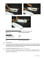
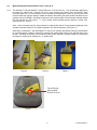
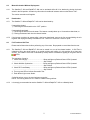
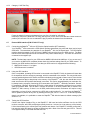
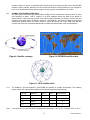
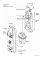
OWNER_____________________________
VESSEL_____________________________
RADIO CALL SIGN_____________________
Product Support Manual
Satellite2 406™ & RapidFix™
Emergency Position Indicating Radio Beacon
Product No. 2774 Cat.1
Product No. 2775 Cat.2
Product No. 2776 GPS Interface Cat.1
Product No. 2777 GPS Interface Cat.2
RLB-32/33
Y1-03-0148
Rev. F
FCC Type Accepted
ACR Electronics, Inc.
5757 Ravenswood Road
Fort Lauderdale, Fl 33312
Tel : +1(954) 981-3333
Fax: +1 (954) 983-5087
www.acrelectronics.com
Email: [email protected]
* * * WARNING * * *
THIS TRANSMITTER IS AUTHORIZED FOR USE
ONLY DURING SITUATIONS OF GRAVE
AND IMMINENT DANGER
DELIBERATE MISUSE MAY
INCUR A SEVERE PENALTY
1
Y1-03-0148 Rev. F
Foreword
Congratulations and thank you for purchasing the ACR Satellite2™ 406 or RapidFix™ 406 Emergency Position
Indicating Radio Beacon. The combination of superior design, high quality raw materials and quality controlled
manufacturing produce a product that will perform for years to come. The test facility at ACR can reproduce some
of the harshest environmental conditions known to man. This assures that the products we produce can stand up
to the rigors found in a marine environment. With proper care and maintenance, your EPIRB will be in service for
years to come.
ACR is proud to be certified to the ISO 9001:2000, the International Standard for Quality.
This manual provides installation, operation and maintenance instructions for the Satellite2™ 406 and RapidFix™
406 EPIRB, hereinafter referred to as the beacon. This manual also describes the characteristics and details of the
beacon system. The FCC authorizes the use of 406 MHz Radio beacon by any ship that is also equipped with a
VHF ship station. This will make the 406 MHz Radio beacon available for use on most U.S. ships and boats.
EPIRB carriage requirements are contained in USCG regulations.
Table of Contents
SECTION 1 - REGISTRATION OF 406 MHZ BEACONS........................................................... 3
1.1
Registration Importance............................................................................................. 3
1.2
Where to register ........................................................................................................ 3
1.3
Registration in the United States............................................................................... 3
1.4
Registration Outside of the United States ................................................................ 4
1.5
Change of ownership or contact information........................................................... 4
1.6
Commercial Vessels World Wide .............................................................................. 4
1.7
Lost or Stolen EPIRB’s............................................................................................... 4
SECTION 2 - FALSE ALARMS .................................................................................................. 4
2.1
Prevention of false alarms. ........................................................................................ 4
2.2
Reporting of false alarms........................................................................................... 5
SECTION 3 - INSTALLATION.................................................................................................... 5
3.1
Mounting Location (Product No 2774, 2775, 2776 and 2777) .................................. 5
3.2
Visual Inspection ........................................................................................................ 6
3.3
Hydrostatic Release Dating Instruction (Product No. 2774 & 2776) Cat 1. ............ 6
SECTION 4 - OPERATION......................................................................................................... 7
4.1
General ........................................................................................................................ 7
4.2
Automatic Deployment and Activation (Cat. 1) ........................................................ 7
4.3
Manual Deployment and Activation (Cat. 1 and Cat. 2) ........................................... 8
4.4
Manual Activation Without Deployment ................................................................... 9
4.5
Deactivation ................................................................................................................ 9
4.6
Full Functional Self Test ............................................................................................ 9
4.7
External GPS Interface (P/N 2776 & 2777 only) ...................................................... 10
SECTION 5 - CARE AND MAINTENANCE.............................................................................. 11
5.1
Routine Maintenance................................................................................................ 11
5.2
Hydrostatic Release.................................................................................................. 11
5.3
Battery Replacement ................................................................................................ 11
SECTION 6 – THE SEARCH AND RESCUE SYSTEM............................................................ 12
6.1
General Overview...................................................................................................... 12
6.2
Satellite Detection..................................................................................................... 12
6.3
GLOBAL POSITIONING SYSTEM (GPS).................................................................. 13
SECTION 7- AUTHORIZATIONS ............................................................................................. 14
7.1
Characteristics .......................................................................................................... 14
7.2
Technical Data — Satellite2™ 406 and RapidFix™ 406 ......................................... 14
7.3
Specifications............................................................................................................ 14
2
Y1-03-0148 Rev. F
SECTION 1 - REGISTRATION OF 406 MHZ BEACONS
1.1
Registration Importance
It is mandatory that the owner of this 406 MHz beacon registers it with the National Authorities.* All 406
MHz beacons transmit a Unique Identifier Number (UIN) when activated. This UIN is programmed in the
beacon based on the country in which the beacon was purchased. Registration provides the search and
rescue forces with up to date emergency contact information, which will speed up the launch of a rescue
operation. The National Authorities use the information to verify if an actual emergency exists. Valuable
search and rescue resources are wasted every year responding to false alarms. For beacon s that are not
registered, SAR forces will not know who you are, what type of vessel you have, your homeport, or who to
contact that might know of your current situation. This will delay the launch of a rescue operation.
406 MHz beacons are required to have their registration updated every two years.
* National Authority is the governmental body that is responsible for EPIRB registration database
administration for the country the EPIRB is programmed for.
1.2
Where to register
The owner of a 406 MHz beacon (EPIRB) should register it with the National Authority of which the beacon
was programmed, (typically the country where purchased), regardless of where they do their boating. Each
beacon is programmed with a UIN for the country that the unit is shipped to, and will only be accepted for
registration in that country. To verify the country, for which a beacon is programmed, see the label with the
UIN on the side of the unit. Units that do not have a country specified on the UIN label are programmed for
the United States.
1.3
Registration in the United States
It is the owner’s responsibility to register 406 MHz beacons that are programmed for and purchased in the
United States. The National Authority that accepts registrations in the United States is the National
Oceanic and Atmospheric Administration (NOAA). The owner should complete the enclosed registration
form (Do not confuse this with the ACR Electronics warranty card) and mail with the pre-addressed;
postage paid envelope to:
SARSAT Beacon Registration,
E/SP3, RM 3320, FB-4
NOAA/NESDIS
5200 Auth Rd.
Suitland, MD 20746-4304
For Faster Service, Register online!
www.beaconregistration.noaa.gov
The information provided on the registration form is used only for rescue purposes. The registration form
should be filled out and mailed immediately. Registration can be expedited by faxing the registration form
to Fax # (301) 568-8649 or register online. Registrations should be completed online or faxed in the event
the beacon is to be placed in immediate service and followed up with the mailing of the hard copy form.
All registration forms will be entered in the 406 MHz beacon registration database within 48 hours of
receipt. A confirmation letter, a copy of the actual registration and a proof-of-registration decal will be
mailed to you within two weeks. When you receive these documents, please check the information
carefully and affix the decal to your beacon in the area marked “Beacon Decal here”. If you do not receive
confirmation back from NOAA, please call toll free 1-888-212-7283 for assistance.
1.3.1
Commercial Vessels in the United States
In the United States, commercial vessels that are required to have a radio station license are required to
modify that license when an EPIRB is added to the vessel. Please use the enclosed FCC FORM 506 to
modify your radio station license. For information on whether you need a radio station license, call toll free
1-888-CALLFCC (225-5322).
3
Y1-03-0148 Rev. F
1.4
Registration Outside of the United States
In countries other than the United States, 406 MHz beacons are registered with that country’s National
Authority at the time of purchase. The sales agent should assist in filling out the forms and sending to that
country’s National Authority. To verify that the unit is properly programmed for that country, view the UIN
label on the side of the unit. In the event that the beacon is not programmed for the country it has been
purchased in, the sales agent, (if properly equipped) can reprogram the unit for that country.
1.5
Change of ownership or contact information
It is the owner’s responsibility to advise the National Authority of any change in the information on the
registration form. If the current owner of the beacon is transferring the beacon to a new owner, the current
owner is required to inform the National Authority by letter, fax or telephone, of the name and address of
the new owner. The new owner of the beacon is required to provide the National Authority with all of the
information requested on the registration form. This obligation transfers to all subsequent owners.
Registration forms are available from NOAA.
Call 1 (888) 212-7283 or visit our website at
www.acrelectronics.com.
1.6
Commercial Vessels World Wide
406 MHz beacons that are carried on commercial vessels world wide, should be registered with the
country where the vessel is flagged regardless of where the vessel operates. When a commercial vessel
acquires a 406 MHz beacon from outside of its home country; the beacon should be reprogrammed for the
home country and registered there.
1.7
Lost or Stolen EPIRB’s
Inform NOAA immediately at 1-888-212-SAVE (7283), or your national authority, that your EPIRB has
been lost or stolen. They will update your EPIRB registration information with the appropriate information.
Stolen EPIRB’s, Things That You Need To Do:
• Report to your local authorities that the EPIRB has been stolen.
• Contact NOAA at 1-888-212-SAVE (7283), or your national authority, with the following information
so your EPIRB registration information can be updated with the appropriate remarks:
- Police Department Name - Police Phone Number - Police Case Number
If you’re EPIRB were to activate, the information you provide will be forwarded
to the appropriate search and rescue authorities who will ensure that your EPIRB gets back to you. If
someone attempts to register an EPIRB reported as stolen, NOAA or your national authority will notify the
appropriate police department.
Visit the COSPAS-SARSAT website for more detailed information: www.cospas-sarsat.org
SECTION 2 - FALSE ALARMS
2.1
Prevention of false alarms.
An ACR 406 MHz EPIRB can be activated by two different methods. Whether you have a Category 1 or 2;
these methods are the same.
1. When the beacon is out of its bracket and in the water, the unit is transmitting.
2. When the switch is moved to the on position, in or out of the bracket, the unit is transmitting.
There are a few precautions that should be taken to prevent false alarms.
• Do not mount or transport beacon within 1 meter (3.3ft) of a magnetic source.
• Do not store beacon outside of its bracket if it can get wet.
• Do not mount EPIRB backwards in its bracket.
• Do not clean beacon with a water hose and brush.
4
Y1-03-0148 Rev. F
2.2
Reporting of false alarms
Should there be, for any reason, an inadvertent activation or false alarm, it must be reported to the nearest
search and rescue authorities. The information that should be reported includes the EPIRB Unique
Identifier Number (UIN), date, time, duration and cause of activation, as well as location of beacon at the
time of activation.
2.2.1
To report false alarms in the United States contact any of the following:
Atlantic Ocean / Gulf of Mexico
USCG Atlantic Area Command Center
Tel: (757) 398-6390
Pacific Ocean Area \ USCG Area Command Center
Tel: (510) 437-3700
From Any Location
USCG HQ Command Center
Tel (800) 323-7233
2.2.2
To report false alarms worldwide contact your national authority.
SECTION 3 - INSTALLATION
3.1
Mounting Location (Product No 2774, 2775, 2776 and 2777)
3.1.1
The location selected must be sufficiently rigid to support the weight of the total installation and at the
same time consider vibration, exposure to the elements, exposure to surrounding hazards, such as
equipment movement, doors being opened, accidental covering, personnel traffic, etc., and yet be readily
accessible at all times for the emergency use for which the beacon is intended.
3.1.2
Also to be considered in selecting a location for installation is the harmful effect that certain corrosive
vapors might have on the beacon. Under no circumstances should a location be selected for installation
where the beacon would be jeopardized by any foreign articles being temporarily or permanently
positioned during “at sea” or “in port” activities.
3.1.3
Beacon should face inboard on rail mount applications and should not be subjected to breaking waves.
CAUTION: Care must be taken to prevent any lanyard, line, or other emergency equipment that may be
attached to the beacon from becoming entangled or fouled which could prevent the beacon from being
removed in an emergency.
3.1.4
Do not mount the beacon in the vicinity (3.3 ft) of strong magnetic (such as loud speakers) or electrical
(such as radar or high power radio transmitter) fields. The beacon should not be mounted closer than (3.3
ft) to a navigation compass.
3.1.5
Consideration should be given to mounting the beacon in a vertical (antenna upward position). In certain
circumstances, such as medical emergencies or disabled vessels, manual activation of the EPIRB for
location and homing purposes is sometimes requested. Mounting in this orientation provides the best
homing signal.
3.1.6
The Satellite2™ 406 and RapidFix™ 406 (Product No. 2774 & 2776) Cat. 1 float-free mounting bracket
should be mounted securely to a vertical or horizontal surface (the mount has predrilled holes for
attachment to a flat surface) where there are no overhead obstructions. Location aboard a vessel must be
chosen to allow the EPIRB to float free of sinking craft and as high as possible especially on small vessels.
This will help ensure operation of the hydrostatic release unit in the event the vessel capsizes without
sinking.
3.1.7
The Satellite2™ 406 and RapidFix™ 406 (Product No. 2774 & 2776) Cat. 1 float-free mounting bracket
should be securely attached to the vessel. The use of #10 stainless steel hardware is recommended. To
access third mounting hole it is necessary to remove the hydrostatic release and allow spring to deploy.
Hold spring with one hand and slide hydro up into keyway. Be careful to release spring slowly. Mount
bracket to wall and reassemble. See Figures 1, 2 and 3.
5
Y1-03-0148 Rev. F
FIGURE 1
FIGURE 2
FIGURE 3
Mounting Case (Product No's 2774 & 2776 only)
Construction
White High Impact and UV resistant plastic
Size
6.5" x 17.1" (16.51 cm x 43.4 cm)
Release System
Hydrostatic with manual override
Replacement Parts
GPS Plug RapidFix Cat 1
GPS Plug RapdiFix Cat 2
Hydrostatic Release Kits
9388.1
9388
9490
Optional Mounting Brackets are available for Product No's 2775 and 2777.
Construction
White High Impact and UV resistant plastic
Size
6.0" x 7.7" (15.2 cm x 19.5 cm)
3.2
Visual Inspection
3.2.1
Visually inspect the area surrounding the mounting bracket installation site for hidden hazards, obstacles,
etc., that may have been overlooked during selection. If there is any doubt as to the ready accessibility to
the beacon at all times or if any condition may appear to be questionable, make complete and thorough
investigation before making final approval of the installation.
3.3
Hydrostatic Release Dating Instruction (Product No. 2774 & 2776) Cat 1.
3.3.1
The label on the hydrostatic release mechanism inside of the bracket and the replacement date label on
the outside of the bracket MUST be marked with the date of expiration at time of installation according to
coastal marine authority regulations.
6
Y1-03-0148 Rev. F
To record the expiration date on the hydrostatic release mechanism, mark or scratch the dates on the label
to indicate the month and year two years from date of installation. Write the date of expiration with an
indelible marker on the outside cover.
SECTION 4 - OPERATION
4.1
General
4.1.1
The Satellite2™ 406 and RapidFix™ 406 beacon Models (Product No. 2774 & 2776) Cat. 1 are designed
to be automatically deployed and activated. The beacon may also be hand held on the deck of vessels, or
floated in water and attached to a raft or life vest with the lanyard provided. The beacon is designed to
operate best while floating in water. Hand held operation should be avoided when possible. (Product
No. 2775 & 2777) Cat. 2 are designed to be manually deployed from its bracket. Do not operate inside life
raft or under any similar cover or canopy. Use the lanyard to attach beacon to life raft or person after
deployment. Caution - Do not attach lanyard to bracket or vessel.
4.1.2
Both Cat.1 (Product No. 2774 & 2776) and Cat.2 (Product No. 2775 & 2777) beacons can be deployed
and activated manually.
4.1.3
Changes in the laws governing beacons have mandated that the beacon be armed at all times. If certain
criteria are met, the beacon will begin transmitting.
The Satellite2™ 406 and RapidFix™ 406 are equipped with sensors to detect when the beacon is no
longer in its bracket (a deployment condition) and other sensors to determine if it is in water.
Two conditions must be satisfied for the Satellite2™ 406 and RapidFix™ 406 to automatically activate:
1) It must be out of its bracket
2) It must be in the water
Note: Either condition by itself will not automatically activate the beacon.
4.1.4
The Satellite2™ 406 and RapidFix™ 406 are designed to allow the user to perform periodic testing while
EPIRB is in the release bracket to assure a functioning beacon.
4.1.5
Place the Satellite2™ 406 and RapidFix™ 406 Cat. 1 (Product No. 2774 & 2776) into the release bracket
with the coiled lanyard inward. The beacon should now be firmly held in the Cat.1 bracket and ready for
automatic deployment. Do not attach lanyard to bracket.
4.1.6
Place the Satellite2™ 406 and RapidFix™ 406 Cat. 2 (Product No. 2775 & 2777) into the bracket with the
coiled lanyard inward. The beacon should now be firmly held in the Cat. 2 bracket and ready for manual
deployment. Do not attach lanyard to bracket. Use the strap and buckle to secure the beacon. The strap
should be adjusted tight against the beacon; tight enough that is almost difficult to engage the buckle.
4.2
Automatic Deployment and Activation (Cat. 1)
(Product No. 2774 and 2776 only)
4.2.1
Automatic deployment and activation occurs when the vessel sinks and a hydrostatic release device frees
the beacon from the bracket allowing it to float to the surface. Built-in sensors detect that the beacon is no
longer in its bracket and is in water. This condition will automatically activate the beacon.
Note: Transmissions of the 121.5 MHz and 406 MHz signal will not occur until 100 seconds after
activation.
Product number 2774 and 2776 Satellite2™ 406 and RapidFix™ 406 (Cat.1) may be deployed and
activated automatically by the built-in hydrostatic float free release. Once free from the release bracket, the
beacon will automatically turn on if the water sensors are wet.
7
Y1-03-0148 Rev. F
4.3
Manual Deployment and Activation (Cat. 1 and Cat. 2)
4.3.1
The Satellite2™ 406 and RapidFix™ 406 (Product No. 2774 & 2776) Cat. 1 can be manually deployed by
removing the retaining pin, removing the cover, then removing the beacon from the bracket. Once
removed, either Cat.1 or Cat.2 beacons can be activated by being placed in water or by lifting the thumb
switch towards the antenna, sliding it toward the antenna and placing the thumb switch back down on the
opposite side of the EPIRB. Activating the beacon in this manner breaks off the Activation Indicator Plastic
Pin and exposes the "ON" symbol " I " on the thumb switch indicating that the beacon is turned "ON".
(See Figures 4, 5, 6 and 7)
Note: Some countries may fine vessel owners for causing false alarms. The permanent breakage of the
Activation Indicator Plastic Pin is a positive indication of a manual activation. (See Figure 7).
Alternately, the Satellite2™ 406 and RapidFix™ 406 can be manually activated by lifting the thumb switch
to a vertical position, sliding it toward the antenna and pushing back down to the opposite side of the
EPIRB. Activating the beacon in this manner breaks off the "Activation Indicator Plastic Pin" and allows
the switch to properly seat, showing the " I " symbol (ON).
Figure 4
Figure 5
Figure 6
Tab will break
when pushed
down to activate
Figure 7
8
Y1-03-0148 Rev. F
4.4
Manual Activation Without Deployment
4.4.1
The Satellite2™ 406 and RapidFix™ 406 can be activated while still in its bracket by placing the thumb
switch in the ON position. Activation by this method overrides all sensors and turns the beacon “ON”.
The caution note above still applies.
4.5
Deactivation
4.5.1
The Satellite2™ 406 and RapidFix™ 406 can be deactivated by:
If manually activated:
1) Returning the thumb switch to the “OFF” position.
If automatically activated:
1) Removing the beacon from the water. The beacon normally takes up to 12 seconds to deactivate, or
2) Placing the beacon back into the release bracket.
4.5.2
If the beacon continues to operate after it has been deactivated, remove the four screws holding the unit
together and unplug the battery to disable the unit. Return it to a Service Center for repair.
4.6
Full Functional Self Test
Please read all instructions before performing any of the tests. Be prepared to record data from the test.
4.6.1
The Satellite2™ 406 and RapidFix™ 406 can be tested in or out of the release bracket. A Self Test is
initiated by lifting the thumb switch to a vertical position and holding it in this position for at least one
second. The initiation of the test is indicated by a beep and the simultaneous lighting of the green and red
LED's.
The sequence of tests is:
1. Check Data Integrity ....................................... Beep and lights up Red and Green LEDs if passed
............................................................................. Stop if failed
2. Check 406 MHz Synthesizer .......................... Beep and lights up Red and Green LEDs if passed
........................................................................... Stop if failed
3. Check RF Power/Battery ................................ Beep and lights up Red and Green LEDs if passed
........................................................................... Stop if failed
4. Turn on green LED to indicate Successful Test.
5. Flash Strobe Light to test Strobe.
If all of the above occurs, the test has been successful.
NOTE: The homing beacon at 121.5 MHz is inhibited during self test.
4.6.2
It is strongly recommended to test the Satellite2™ 406 and RapidFix™ 406 on a Monthly basis.
9
Y1-03-0148 Rev. F
4.6.3
Category 1 Self Test Plug
Figure 8
Forget the hassle of removing the beacon from your Cat. 1 bracket for self testing.
Now simply remove the New Self Test Plug (See figure 8) on the front cover and have instant access to
perform your self tests. Be sure to reattach the plug to protect the beacon from the elements.
4.7
External GPS Interface (P/N 2776 & 2777 only)
4.7.1
Connecting the RapidFix™ 406 to a GPS via the Optical Interface (IR Transmitter)
Your RapidFix™ 406 comes with a GPS Optical Interface (transmitter plug with lead wires) and a keyed
GPS bezel. The transmitter plug attaches to your RapidFix™ 406, via the keyed bezel. The GPS Optical
Interface lead wires attach to your GPS via the NMEA 0183 connector from your GPS receiver. The black
lead wire with white stripes should be connected to the positive transmitter pin. The black wire should be
connected to the negative pin.
NOTE: The baud rate output for your GPS receiver NMEA 0183 should be 4800 bps. If you are not sure if
your receiver is NMEA 0183 compliant please check the interface settings listed in your GPS manual. To
optimize your GPS Interface feature be sure that your GPS receiver is equipped with the following:
• NMEA 0183 Version 1.5 or higher
• GPGGA sentence is enabled
4.7.2
Using the GPS Interface
Once a compatible, operating GPS receiver is connected to the RapidFix™ 406, the beacon will store data
for incorporation into the emergency message, which is transmitted to the satellite. This can provide more
accurate positioning data to the Search and Rescue Authority and may lead to faster rescue. Since the last
valid GPS position data is always kept in the memory of the RapidFix™ 406, the user should take care to
make sure that the GPS position data stored is accurate. This can be accomplished by two methods: first,
by always leaving a properly functioning GPS connected to the RapidFix™ 406 before activation. Second,
by connecting a properly functioning GPS with a valid position fix and allowing sufficient time to acquire
valid GPS position data. This will take a nominal 20 minutes if old GPS position data is stored in the
RapidFix™ 406’s memory. If there is no old GPS position data present, the beacon will acquire current
data within a minute of being connected to a GPS with a valid position fix. You can force the RapidFix™
406 to update its position at any time by initiating the Self-Test, see 3.7.3 and 3.7.4. If valid GPS position
data is not available, it is preferable to reset the RapidFix™406 with the beacon’s default message (See
Section 3.7.5).
4.7.3
Testing the GPS Interface
Connect the Optical Interface Plug to the RapidFix™ 406 bezel and allow sufficient time for the GPS
receiver to acquire valid GPS position data (usually less than 1 minute; but it can take up to 30 minutes).
Lift the thumb switch to the vertical (Self-Test) position and release. Your RapidFix™ 406 will confirm that it
has acquired valid GPS data by emitting a beep along with a flash of the red and green LED’s. This will
occur approximately 2.5 seconds after the Self-Test.
10
Y1-03-0148 Rev. F
4.7.4
Updating GPS Position data
When the beacon is properly connected to a functioning and compatible GPS receiver, GPS position data
is automatically updated about every 20 minutes, while valid GPS position data is present. The operator
can force the acquisition of new GPS position data, by executing Self-Test of the beacon. This bypasses
the normal, programmed, waiting time of 20 minutes for the automatic update of GPS position data. Once
the RapidFix™ 406 has completed the Self-Test sequence by emitting the beep and flash of red and green
LEDs, as described in 3.7.3, the RapidFix™ 406 will request and acquire new position data from the GPS.
This can take a nominal 15 seconds or up to one minute.
NOTE: When the beacon is not activated, GPS position data will be received and stored by the RapidFix™
406 (No GPS position data updates will occur while the beacon is activated).
4.7.5
Position data set to default
A new RapidFix™ 406 is programmed with the GPS position data set to “default”. This “default” GPS
position data indicates, upon activation, to the satellite system that the beacon has no valid GPS position
stored in memory. Once a functioning and compatible GPS receiver is properly connected to the beacon,
this “default” data will be replaced by valid G PS position data, as described in the previous sections.
Position data will be reset to default by activating the beacon (turning the beacon ON) and then turning the
beacon OFF.
NOTE: The RapidFix™ 406 should never be turned “ON” except in situations of imminent danger.
ALSO NOTE: The action of turning the beacon ON and then OFF clears any stored GPS position data.
SECTION 5 - CARE AND MAINTENANCE
5.1
Routine Maintenance
At least every ninety days, the float free mounting bracket and Satellite2™ 406 and RapidFix™ 406 EPIRB
should be inspected for deterioration and/or buildup that may affect the function of the beacon or automatic
release.
Also carefully inspect the EPIRB case for any visible cracks. Cracks may admit moisture, which could
falsely activate the beacon or otherwise cause a malfunction. Any cracking observed should be
immediately referred to ACR for evaluation, (1-800-432-0227 Ext. 112)
Clean the beacon and the mounting bracket to remove residue buildups. It is recommended that the
mounting bracket be wiped with a damp cloth.
5.2
Hydrostatic Release
The hydrostatic release unit (HRU) must be replaced by the date indicated on the float free mounting
bracket. The hydrostatic release can be replaced by removing the beacon from the bracket, then sliding
the hydrostatic release assembly out of the keyed opening on the spring and mounting bracket. Insert the
new hydrostatic release assembly, in place by engaging it to the opening of the ejection spring and case.
When servicing the HRU, ACR requires that you replace the entire hydrostatic assembly, including
hydrostatic release, release rod and all hardware (P/N 9490). Failure to replace the entire assembly can
cause the bracket to malfunction. Always use original ACR replacement parts. Use of unauthorized
replacement parts will void your warranty and may cause the bracket to malfunction. Place beacon into the
mounting bracket, and replace cover, securing in place with hitch pin going through the hydrostatic release
rod.
5.2.1
Check antenna for tightness.
5.3
Battery Replacement
The battery (P/N 1096) must be replaced by the date indicated on the beacon. At each inspection, check
the time remaining until replacement is required. Battery should be replaced if the beacon has been
activated for any use other than the self test.
11
Y1-03-0148 Rev. F
NOTE: There are no user serviceable items inside the EPIRB. DO NOT OPEN THE EPIRB UNLESS TO
DISABLE IN CASE OF FAULTY ACTIVATION.
Self contained long life batteries with a five-year recommended replacement cycle provide power. See
Factory Authorized Service Center for replacement.
Battery replacement includes servicing the EPIRB by replacing all o-rings, testing the water seal and the
electrical properties.
Always refer all long life battery replacement and other EPIRB service to a factory authorized service
center.
For the nearest location of a factory authorized service center, call 1-800-432-0227 Ext. 112 (toll free) or
visit our website at www.acrelectronics.com
5.3.1
The Satellite2™ 406 and RapidFix™ 406 contains lithium batteries which meet the requirements of the
DOT Hazardous Materials Regulations. They also meet the United Nations Classification of Lithium
Batteries for Shipment as "Non – Dangerous Goods".
SECTION 6 – THE SEARCH AND RESCUE SYSTEM
6.1
General Overview
EPIRB’s provides distress alerting via radio transmission on 406 MHz to satellites of the COSPASSARSAT network. The RapidFix™ 406 can also transmit a distress alert to the GEOSAR network that
includes GPS latitude and longitude coordinates that are inputted through an I/R Interface that connects to
the data output of a GPS Receiver.
The message transmitted is unique for each beacon, which provides identification of the transmitter
through computer access of registration files maintained by the National Oceanic and Atmospheric
Administration or other National Authority. Remember, if your beacon is not registered, Search and
Rescue (SAR) Authorities do not know who you are, or how to contact anyone who might know anything
about your situation (Refer to section 1).
Once the signal (406 MHz) is relayed through the LEOSAR and/or GEOSAR network, SAR forces
determine who is closest, and then track the signal using the 121.5 MHz homing frequency for intermediate
and short-range location.
6.2
Satellite Detection
EPIRB’s transmits to the satellite portion of the COSPAS-SARSAT System. COSPAS-SARSAT is an
international system that uses Russian Federation and United States low altitude, near-polar orbiting
satellites (LEOSAR) that assist in detecting and locating activated 121.5/243 MHz beacons and 406 MHz
Satellite beacons.
COSPAS and SARSAT satellites receive distress signals from EPIRB’s transmitting on the frequency of
406 MHz. The COSPAS-SARSAT 406 MHz beacon signal consists of a transmission of non-modulated
carriers followed by a digital message format that provides identification data. The 406 MHz system uses
Satellite-borne equipment to measure and store the Doppler-shifted frequency along with the beacons
digital data message and time of measurement. This information is transmitted in real time to an earth
station called the Local User Terminal (LUT), which may be within the view of the satellite, as well as being
stored for later transmission to other LUTs.
The LUT processes the Doppler-shifted signal from the LEOSAR and determines the location of the
beacon; then the LUT relays the position of the distress to a Mission Control Center (MCC) where the
distress alert and location information is immediately forwarded to an appropriate Rescue Coordination
Center (RCC). The RCC dispatches Search and Rescue (SAR) forces.
The addition of the GEOSAR Satellite system greatly improves the reaction time for a SAR event. This
satellite system has no Doppler capabilities at 406 MHz, but will relay the distress alert to any of the LUT
stations. When there is GPS data included in the distress message, SAR authorities instantly know your
12
Y1-03-0148 Rev. F
location to within 110 yards. This speeds up the reaction time by not having to wait for one of the LEOSAR
satellite to pass overhead. Because most of the search and rescue forces presently are not equipped to
home in on the 406 MHz Satellite beacons signal, homing must be accomplished at 121.5 MHz.
6.3
GLOBAL POSITIONING SYSTEM (GPS)
The GPS system is a satellite group that enables a GPS receiver to determine its exact position to within
30m anywhere on Earth. With a minimum of 24 GPS satellites orbiting the Earth at an altitude of
approximately 11,000 miles they provide users with accurate information on position, velocity, and time
anywhere in the world and in all weather conditions. The RapidFix™ 406 stores this data into its distress
transmission allowing search and rescue forces to narrow the search into a very small area and thus
minimize the resources required and dramatically increases the effectiveness of the overall operation.
Figure 9- Satellite coverage
Figure 10- GEOSAR satellite orbits
Figure 11- GPS satellite orbits
6.3.1
Note:
The Satellite2™ 406 and RapidFix™ 406 EPIRB are available in multiple combinations. The following
product codes define the options available to meet specific operational requirements:
Prod. No.
Model No.
2774
RLB-32
2775
RLB-32
2776
RLB-33
2777
RLB-33
Cat. 1
Cat. 2
GPS Interface
X
X
X
X
X
X
All models above conform to Class 1 Requirements (Operations: –40°C to 55° C storage: -50°C to 70°C)
13
Y1-03-0148 Rev. F
SECTION 7- AUTHORIZATIONS
The Satellite2™ 406 and RapidFix™ 406 EPIRB meets the requirements of Federal Communications
Commission (FCC) Part 80 (Product No.'s 2774, 2775, 2776, and 2777) and GMDSS (Product No.'s 2774
and 2776)
7.1
Characteristics
7.1.1
The Satellite2™ 406 and RapidFix™ 406 EPIRB is a floatable, battery operated unit. The beacon case,
with its external antenna, is waterproof. The semiconductor circuits are mounted within the case assembly
that also contains the battery power supply. A “Test/On” switch is installed on top of the beacon, along with
a strobe light. The beacon must be stored in its special mount, free of obstructions aboard a vessel for
automatic float-off. The unit is self-buoyant and no external floatation devices are required.
7.2
Technical Data — Satellite2™ 406 and RapidFix™ 406
7.2.1
Applicable Documents
RTCM
COSPAS-SARSAT
FCC
MED
7.3
Standard for 406 MHz Satellite EPIRBs
Certificate No. 107 (RLB-32)
Certificate No. 108 (RLB-33)
Document C/S T.001
Document C/S T.007
Part 80 and GMDSS (Product No.'s 2774 & 2776)
Registration number 6492/050564-1/2004 (RLB-32)
Registration number 6492/050564-2/2004 (RLB-33)
Notified Body: 0735
Specifications
406 MHz Transmitter
Frequency
Frequency Stability
Output Power
Digital Message
Format
406 MHz
±2 parts per billion/100ms
5 watts
RLB-32: Serialized1
RLB-33: Serialized2
Duration
440 ms (RLB-32)
520 ms (RLB-33)
Rate
400 bps
Encoding
Biphase L
Modulation
±1.1 radians peak
1
Leaves ACR with Serialized U.S. code but can be reprogrammed at a service center to Maritime or other
coded format including nationality of registration.
2
Leaves ACR with Serialized U.S. code but can be reprogrammed at a Service center to Maritime MMSI.
121.5 MHz Transmitter
Frequency
Frequency Tolerance
Output Power
Modulation
Type
Sweep Range
Sweep Rate
Duty Cycle
AM (3K20A3X)
400 to 1200 Hz
3 Hz
37.5%
Antenna
Frequency
Polarization
VSWR
406 & 121.500 MHz
Vertical
Less than 1.5/1
121.5 MHz
±50 ppm
25 mW PEP
14
Y1-03-0148 Rev. F
Xenon Strobe
Light Color
Output Power
Flash Rate
White
0.75 effective candela
20—30 per minute
General/Environmental
Battery Life
Operating
Replacement Interval
48 hours minimum
5 years or after use in an emergency
Temperature Range
Operating
Storage
Class I -40°C to +55°C
CLASS I
-50°C TO +70°C
Size (EPIRB less Antenna)
7.0 x 4.25 x 3.62 in. (17.8 x 10.8 x 9.2 cm)
Antenna Height
EPIRB Material
Color
Weight
7.39" (18.77 cm)
High impact and UV resistant plastic
Yellow
1.9 lbs. (861 g)
Exceeds RTCM Standards - Factory Tested to 10
meters at room temperature
Waterproof
Figure 12
15
Y1-03-0148 Rev. F
Figure 13
16
Y1-03-0148 Rev. F
Figure 14
17
Y1-03-0148 Rev. F
ACR Electronics, Inc.
5757 Ravenswood Road, Ft. Lauderdale,
FL 33312-6645
Tel: +1 (954) 981 3333 Fax: +1 (954) 983-5087
http://www.acrelectronics.com
European Office
1 Rose Cottages, Pitmore Lane, Sway,
Lymington, Hampshire SO41 6BX UK
Tel: +44-1590-682282 Fax: +44-1590-683828
E-mail: [email protected]
MARINE EQUIPMENT DIRECTIVE
DECLARATION OF CONFORMITY
We hereby declare that the following product is in conformity with the Council Directive
96/98/EC of 20 December 1996 on Marine Equipment as amended by Commission Directive
2002/75/EC of 2 September 2002 and that it has been type examined as follows.
Product
Beacon
: 406 MHz (COSPAS-SARSAT) Emergency Position Indicating Radio
(EPIRB) ACR RapidFix™ 406 RLB-33 (Cat. 1 & Cat. 2)
Notified Body
: Bundesamt fϋr Seeschifffahrt und Hydrographie (BSH) – Germany
Notified Body No. 0735
Certificate No.6492/050564-2/2004
Type Examination : Annex A.1, Item No. A.1/5.6 and Annex B, Module B in the Directive
Standards
IMO Res. A.810(19)
IMO MSC.56(66), MSC.120(74)
IMO MSC/Circ.862
IMO Res. A.694(17)
IEC 61097-2
IEC 60945
ETS 300 066
COSPAS-SARSAT C/S T.001
COSPAS-SARSAT C/S T.007
Manufacturer
: ACR Electronics Inc. Fort Lauderdale, Florida, USA
EU Representative : ACR Electronics Inc. (European Office)
Lymington, Hampshire UK.
Signed on behalf of ACR Electronics Inc.
Signed : _________________________________
Name: John F. Flood
Date : April 11, 2006
Title: V.P. Engineering
18
Y1-03-0148 Rev. F
ACR Electronics, Inc.
5757 Ravenswood Road, Ft. Lauderdale,
FL 33312-6645
Tel: +1 (954) 981 3333 Fax: +1 (954) 983-5087
http://www.acrelectronics.com
European Office
1 Rose Cottages, Pitmore Lane, Sway,
Lymington, Hampshire SO41 6BX UK
Tel: +44-1590-682282 Fax: +44-1590-683828
E-mail: [email protected]
MARINE EQUIPMENT DIRECTIVE
DECLARATION OF CONFORMITY
We hereby declare that the following product is in conformity with the Council Directive
96/98/EC of 20 December 1996 on Marine Equipment as amended by Commission Directive
2002/75/EC of 2 September 2002 and that it has been type examined as follows.
Product
Beacon
: 406 MHz (COSPAS-SARSAT) Emergency Position Indicating Radio
(EPIRB) ACR Satellite2 406™ RLB-32 (Cat. 1 & Cat. 2)
Notified Body
: Bundesamt fϋr Seeschifffahrt und Hydrographie (BSH) – Germany
Notified Body No. 0735
Certificate No.6492/050564-1/2004
Type Examination : Annex A.1, Item No. A.1/5.6 and Annex B, Module B in the Directive
Standards
IMO Res. A.810(19)
IMO MSC.56(66), MSC.120(74)
IMO MSC/Circ.862
IMO Res. A.694(17)
IEC 61097-2
IEC 60945
ETS 300 066
COSPAS-SARSAT C/S T.001
COSPAS-SARSAT C/S T.007
Manufacturer
: ACR Electronics Inc. Fort Lauderdale, Florida, USA
EU Representative : ACR Electronics Inc. (European Office)
Lymington, Hampshire, UK.
Signed on behalf of ACR Electronics Inc.
Signed : _________________________________
Name: John F. Flood
Date : April 11, 2006
Title: V.P. Engineering
19
Y1-03-0148 Rev. F