1
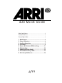
435 Quick Guide
Safety Specifications .......................................................2
Camera Left & Front........................................................3
Camera Right & Back .....................................................4
1.
2.
3.
4.
5.
6.
7.
8.
9.
Quick Specs.................................................5
Status Indicators..........................................6
Loading Magazines .....................................7
Threading ...................................................9
Power On, Camera RUN, Inching...............11
Changing Fps ............................................12
Changing Shutter Angle.............................13
Timecode Sensitivity Table .........................15
Arri Group Addresses ................................16
4/99
Safety Specifications
About This Quick Guide
In order to ensure optimal performance, it is essential that you acquaint yourself with this Quick Guide and
that you follow the operating instructions described herein. First time users must acquaint themselves with the
full 435 instruction manual. Even though all efforts have been made to ascertain the accuracy of this Guide,
changes and upgrades to the products described can result in different hardware or behavior. In other
words, technical data are subject to change without notice.
Best viewing and printing of the Acrobat (pdf) version of this Quick Guide can be achieved through the use
of the Acrobat Reader 3.0 or later. For best printing results, use a PostScript printer. The Acrobat Reader can
be downloaded for free from the Adobe web site at http://www.adobe.com.
435 and 435ES
The ARRIFLEX 435 is available in two different models: the 435ES is equipped with an electronic shutter and
a FEM (Functional Expansion Module). The standard 435 has a manually adjustable shutter and no FEM.
Please note that the FEM is needed for the new 24 V accessories (including the CCU, RCU and ESU), for the
LCC (Laptop Camera Controller) and for Timecode use. The FEM can be purchased separately.
Safety Specifications
• The RS, ACC and CCU sockets output the same voltage as is supplied to the BAT socket. If the BAT socket
input voltage is above 32 V, the voltage output of the RS, ACC and CCU sockets will be limited to 32 V/2
amp. Ensure that all accessories are suited to the supplied voltage.
• When transporting the camera, make sure that the sliding door securing the field lens is all the way down.
Newer cameras are fitted with a self-locking safety catch which is activated when the field lens is inserted.
• When using the RCU, always reset the shutter angle to the desired value before disconnecting the RCU.
• Repairs should be carried out only by authorized service centers. Use only original ARRI accessories and
replacement parts.
• Never run the camera without a lens or a protective cap in the lens mount.
• Never place your hand in the lens cavity or the inside of the camera while the camera is running!
• Never open the movement or gate locking mechanism while the camera is running!
• When manually adjusting the mirror shutter, turn the camera off and remove the power cable.
Accidentally running the camera while manually adjusting the mirror shutter can cause great damage.
• Clean optical surfaces only with an optical brush or a clean optical cloth. In cases of solid dirt, moisten an
optical cloth with pure alcohol or a brand-name lens cleaner.
• Do not use solvents when cleaning the film path.
• Do not remove any screws which are secured with paint.
Arriflex 435 Quick Guide, 4/99, Page 2
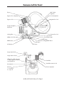
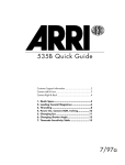
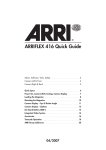
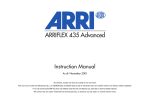
Camera Left & Front
Eyecup
400’ (120m)
magazine
Eyepiece focus adjustment
Door lock safety button
Eyepiece lock
Magazine door lock
Arriglow brightness
adjustment
Locking slider
Camera door lock
Run button
Run indicator light
NORM - PS/CCU switch
MODE button
PROG button
Electronic inching/PHASE button
SEL button
LCD display
SET button
Image rotation knob
Image rotation release
Sliding door (older cameras)
or safety catch (new cameras)
securing field lens
Viewfinder
Ground glass
Viewfinder extension lock
PL mount
1 = normal 35
2 = super 35
Friction adjustment
Arriflex 435 Quick Guide, 4/99, Page 3
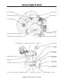
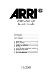
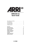
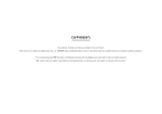
Camera Right & Back
Grip system
Tensioning plate
Video assist port
Mechanical footage counter
Tensioning plate
RS socket
(remote RUN & 24 V dc)
Functional expansion module (FEM)
24 V accessory overload light
Compartment for 9 V timecode battery
Contrast filter lever
Viewfinder swivel release
Tape hook
Grip system
11 pin (12 V) accessory
socket
12 V accessory
overload light
Functional expansion
module (FEM)
Magazine release latch
Bubble level
ACC socket
(accessories)
Magazine opening cover
CCU socket
(camera control unit)
Two 3/8-16 mounting holes underneath camera
Main power on/off switch
Arriflex 435 Quick Guide, 4/99, Page 4
BAT socket (power input)
1. Quick Specs
Fps Range:
ARRIMAG magazines: 1.000 to 150.00 fps, forward and reverse
35-3/2C magazines: 1.000 to 130.00 fps forward; reverse only with
35-3/2C 400’ (120m) magazines. 35-3 shoulder magazines cannot be used.
Mirror Shutter:
435ES:
435:
11.2° to 180.0°, electronically adjustable in 0.1° increments
11.2° to 180.0°, manually adjustable to: 11.2°, 22.5°, 30°,
45°, 60°, 75°, 90°, 105°, 120°, 135°, 144°, 172.8° and 180°
Power:
BAT:
Up to 130 fps: 24 V dc in, above 130 fps: > 24 V dc in
(Use 26 V dc [min. 7Ah] batteries to cover the whole fps range)
Pin 1 is negative, pin 2 is positive
Acceptable voltage range: 20.6 to 35 V dc
RS:
Pin 1: GND, pin 2: nominal 24 V dc out, pin 3: /E-Run
ACC
Pin 4: GND, pin 3: nominal 24 V dc out
CCU:
Pin 4: GND, pin 3: nominal 24 V dc out
11-Pin:
Pin 9: GND, pin 11: 12 V dc out, pin 2: shutter pulse,
pin 7: E-CRUN
Power output: All 24 V dc outputs total: max. 3 amp continuous, 5 amp peak
All 12 V dc outputs total: max. 3 amp continuous, 5 amp peak
The ”nominal 24 V dc out” on the RS, ACC and CCU sockets will
provide the incoming voltage up to +32 V dc.
Fuses:
Movement:
All 435 fuses are self-resetting thermal fuses. If blown, the
respective overload light will illuminate. To reset fuse, disconnect
all accessories and wait for one minute.
Two three-pin pull-down film transport claws and two registration pins
Flange Focal Distance: 51.98 - 51.97 mm
Temperature Range:
-4° Fahrenheit to +122° Fahrenheit (-20°Celsius to +50°Celsius)
Contrast Filter:
Selectable ND 0.6
Electronic Accessories: Integrated Video System (IVS), Integrated Capping Shutter (ICS) and Single
Frame Hand Controller (SFHC), Remote Control Unit (RCU-1), Laptop Camera
Controller (LCC), Lens Control System (LCS), Wireless Lens Control System
(WLCS), Iris Control Unit for speed/iris ramps (ICU-1), Remote On/Off Switch
(RS-4), External Synchronization Unit (ESU-1).
Other Accessories:
400’ (120m) magazine ARRIMAG 120, 400’ (120m) steadicam magazine
ARRIMAG 120S, 1000’ (300m) magazine ARRIMAG 300E, a wide variety of
zoom and prime lenses, shift & tilt lens system, viewfinder extenders,
anamorphic viewfinder, heated eyecup, exchangeable ground glasses and
arriglow masks, various matte box systems, various follow focus systems, right
side on/off button, right side handgrip, hand held shoulder supports,
steadicam support bracket, lens light, accessory connector splitter boxes,
timecode exposure module, batteries, power supply, geared head, varicon
contrast control, obie light
Arriflex 435 Quick Guide, 4/99, Page 5
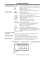
2. Status Indicators
Viewfinder Indicators: Red LED:
ASY:
END:
BAT:
■■ glows:
Display Indicators:
Asynchronous operation; camera is not running at set fps rate
Asynchronous operation; camera is not running at set fps rate
Camera ran out of film
Battery too low for the set fps rate
≤130 fps: less than 20.6 V; 130 - 150 fps: less than 24.1 V
The display is in mode 1
bat glows:
Battery too low for the set fps rate
≤130 fps: less than 20.6 V; 130 - 150 fps: less than 24.1 V
bat flashes:
Battery is too ”soft”, voltage will collapse on use
asy glows:
Asynchronous operation; camera is not running at set fps rate
asy flashes:
Movement and shutter are not synchronous
end glows:
Camera ran out of film
fps flashes:
Wrong magazine for currently set fps rate
or, if connected, ESU is not getting a valid signal
PROG glows: Internal program is activated
PROG flashes: Internal program cannot be run: out-of-range fps or shutter
values, wrong magazine for programmed fps values, or
battery too low for programmed fps values
R glows:
Camera is set to run in reverse
TC glows:
Timecode exposure is enabled and timecode is set
TC flashes:
Timecode exposure is enabled, but not recording properly
OFF:
Lower line: SEL/SET button is pressed & locking slider is locked
OFF:
Upper line in mode 7: electronic shutter of 435ES is off
Shutter flashes: See below
Shutter Flashes (435ES):
Shutter flashes:
Shutter flashes & red LED:
Shutter flashes & red LED:
The electronic shutter adjustment feature of the 435ES has been turned off.
If shutter is locked, it should be unlocked.
If shutter is unlocked, the electronic adjustment feature is defective. Turn
electronic adjustment off and set the shutter manually to continue filming.
Display Warnings:
The LCD Display will indicate any situations that will prevent running the
camera by changing one or more of its digits into underlines.
1000’ (300m) ARRIMAG
300E not ready
ft
fps
No reverse run with 35-3/2C
1000’ (300m) magazine!
00000
_0000
Movement block
not locked
Arriflex 435 Quick Guide, 4/99, Page 6
Secondary shutter/movement
monitor triggered or defective.
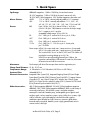
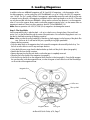
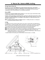
3. Loading Magazines
In addition to the new ARRIMAG magazines, all 35-3 and 35-2C magazines - with the exception of the
shoulder magazines - can be used on the 435. The ARRIMAGs run up to 150 fps, the 35-3/2C magazines
up to 130 fps. The ”fps” symbol will flash if a magazine is attached that cannot be used with the set fps rate
or camera running direction. All magazines are loaded with the same loop length as on the 35-3. Timecode
can only be recorded with the new ARRIMAGs. Always make sure that a loop protector is on the magazine
when it is not on the camera. Always make sure that the magazine opening cover is on the camera when no
magazine is attached. These instructions pertain to the 400’ (120m) ARRIMAG 120.
Note: Reverse operation with 35-3/2C 200’ (60 m) magazines can damage the camera!
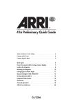
Step 1: The Feed Side
Load unexposed film only in absolute dark - such as in a dark room or changing bag. Short ends load
easier if you cut the film head through the center of the perforations. Ensure that an empty plastic core is on
the take-up shaft before starting the loading procedure.
Note: Make sure that the spring loaded key of the take-up shaft engages into the keyway of the plastic film
core. Failure to do so can lead to film jams, especially during high speed takes!
• Remove the loop protector.
• Push the safety catch on the magazine door lock towards the magazine throat and flip the lock up. Turn
the lock counter clockwise until it stops and open the door.
• Swing both roller arms away from the feed and take-up shafts until they lock in place (see graphic).
• Remove the film from the film container.
• Remove the tape from the film end. Make sure that the tape is completely removed.
• Place the film roll to the left of the magazine (see graphic).
• Push the film into the left slit on the magazine throat from the inside (see graphic). Once the film engages
the sprocket roller inside the magazine throat, turn the drive gear counter clockwise until the film emerges
on the outside of the magazine throat.
Magazine door
Feed shaft
Roller arms
Take-up shaft
Magazine throat
Drive gear
Arriflex 435 Quick Guide, 4/99, Page 7
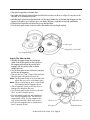
• Flip up the hinged clip on the feed shaft.
• Now place the film on the feed shaft and push the film core down as far as it will go. Do not press on the
film itself, as it could become conical.
• Hold the plastic core and turn the feed shaft until the spring loaded key on the feed shaft engages into the
keyway of the plastic core. Failure to do so can lead to film jams, especially during high speed takes!
• Flip down the hinged clip to lock the film core on the feed shaft.
• Turn the drive gear counter clockwise until the film reaches the loop length marking.
Drive gear
Hinged clip on feed shaft
Loop length marking
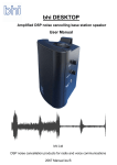
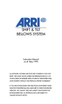
Step 2: The Take-up Side
• Hold the drive gear to keep the loop length
stable. Push the film gently into the right slit on
the magazine throat from the outside until it
engages with the sprocket roller inside the
magazine throat.
• Turn the drive gear counter clockwise to transport
the film into the magazine.
• Fold over the first 1/8th” (5 mm) of the film head.
Place the head in the plastic film core slot.
Note: The film head should not stick out below the
plastic film core, as this could lead to jams!
Note: When running reverse, don’t run the folded
film head through the magazine throat!
• With a fingernail, smooth out the film where it
emerges from the plastic film core.
• Turn the drive gear counter clockwise until some
film is wound on the take-up core.
• Ensure that both hinged clips are locked down,
then close the magazine door. The roller arms
automatically unlock. Turn the magazine door
lock clockwise and flip it back into the recess.
• Pull up on the magazine door to double check
that it is properly locked.
Film loop
Drive gear
Arriflex 435 Quick Guide, 4/99, Page 8
Plastic film core
Magazine throat
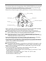
4. Threading
Attaching the Magazine to the Camera
• Remove the magazine opening cover and open the camera door. Make sure that the movement is in the
forward (closed) position.
Upper dovetail area
Magazine release latch
Magazine opening cover
Lower dovetail area
• Hold the magazine above the camera so you can pull the film loop into the camera as far as it will go (see
left graphic below). Position the back of the magazine throat on the lower dovetail of the camera.
• Push the magazine all the way onto the camera to lock it in place. Especially in the upper dovetail area
make sure that the film will not get caught between the magazine and the camera opening!
Note: If the magazine drive gear does not engage the camera drive gear easily, you can slightly turn the
inching knob of the movement to help.
• Pull up on the magazine to double check that it is properly seated and locked on the camera.
Threading the Film
• Pull the film loop out of the camera (see left graphic below) and push it into the upper loop area.
• Slide the film in between the movement and the film gate as far as it will go (see right graphic below).
Upper loop area
Movement
Film gate
Inching knob
Movement in forward
(closed) position
Arriflex 435 Quick Guide, 4/99, Page 9
• Ensure that the white line on the inching knob aligns with the LOADING POSITION line on the movement.
• Turn the movement locking lever to the OPEN position to swing the movement away from the film gate.
Slide the film into its proper place between the film gate and the movement.
• Place the film onto the positioning pin so that the upper film loop is in the center of the film loop marking.
Film loop marking
Positioning pin
Inching knob
Movement locking lever
Film gate
Pitch Adjustment knob
• Make sure that the film is properly positioned along the whole film gate (film edge parallel to gate edge),
and close the movement by turning the movement locking lever counter clockwise.
• To check for proper film transport, turn the inching knob clockwise. Then push the PHASE button.
Note: The LCD display will show the open mirror shutter angle and the battery voltage when the PHASE
button is pushed. This allows you to check these values each time you reload!
Note: The movement and the mirror shutter of the 435 are linked electronically, and will only move
together when the camera is running or when it is inched with the PHASE button. When the camera
is manually inched, the mirror shutter will not rotate.
• Run the camera briefly at 24 fps to check for proper threading. With a little practice you will be able to
hear if there is any problem by the sound of film running through the camera at 24 fps.
• If you have the same film stock loaded that you will be using for the shoot, turn the pitch adjustment knob
while the camera is running at 24 fps until you hear the least amount of movement noise. This will insure
smoother running, especially during high speed takes.
• Close and lock the camera door.
Note: Especially before high speed takes it is a good idea to ensure that the film in the magazine is under
some tension. To do this, press the PHASE button for 5 seconds or briefly run the camera at 24 fps.
• Reset the TOTAL film counter by pushing the SET button for approximately 3 seconds when viewing the
TOTAL counter on the LCD display.
• If you are using Timecode, now is a good time to set the Timecode Sensitivity (TCS) number:
- Look up the proper TCS number from the back of this Quick Guide.
- Press the mode button five times to change to mode 6 on the LCD display. You should see an ”S” and a
number in the bottom line of the display.
- Press the SEL button until the digit to the right of the ”S” flashes. This is the TCS number.
- Press the SET button to change the TCS number.
- Press the SEL button to confirm your entry.
Arriflex 435 Quick Guide, 4/99, Page 10
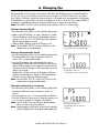
5. Power On, Camera RUN, Inching
Turning Camera Power On
The main power switch for the ARRIFLEX 435 is located on the back of the camera, underneath the
magazine mounting port. When a battery is attached to the camera and the main power switch is turned
on, you should see characters appear on the LCD display on the camera left side. The two accessory
overload lights will also illuminate briefly to show that they are operational.
Camera RUN
The RUN button is located on the left side of the camera. To run the camera, depress the RUN button briefly.
To stop the camera depress the RUN button again briefly.
The RUN indicator light will glow red while the camera is coming up to speed, and switch to green once the
set frame rate is reached. The RUN indicator light will steadily glow green when the camera is running at the
set frame rate. When the RUN button is pushed again to stop camera run, the light will briefly glow red,
then green, and then turn off.
Note: If the RUN indicator light glows red while the camera is in Standby, the camera is not ready and
pushing the RUN button will have no effect.
Inching
The ARRIFLEX 435 can be inched manually with the inching knob or electronically with the PHASE button.
The PHASE button, if pushed very briefly, will also rotate the mirror shutter 180°. This allows for a fast gate
check. To move the mirror shutter back into the viewing position, push the PHASE button again briefly.
• To manually inch the camera, open the camera door and turn the inching knob clockwise.
Note: Any film in the movement area will be exposed to light when inching manually!
Note: Don’t inch the camera to expose images, as correct exposure cannot be guaranteed during inching!
Note: The movement and the mirror shutter of the 435 are linked electronically, and will only move
together when the camera is running or when it is inched with the PHASE button. When the camera
is manually inched, the mirror shutter will not rotate.
• To electronically inch the camera, press the PHASE button while the camera is in Standby.
Main power switch
NORM - PS/CCU switch
LCD display
RUN button
RUN indicator light
Arriflex 435 Quick Guide, 4/99, Page 11
Electronic inching/PHASE button
6. Changing Fps
With the NORM - PS/CCU switch on the camera's left side in the NORM position, the standard speeds of
23.976, 24, 25, 29.97 and 30 fps, forward or reverse, can be run. In the PS/CCU position, any speed
from 1.000 to 150.00 fps, forward or reverse, can be run. All speeds set on the camera are crystal speeds.
The ARRIMAGs run up to 150 fps, the 35-3/2C magazines run up to 130 fps. The ”fps” symbol will flash if
a magazine is attached that cannot be used for the set fps rate or camera running direction.
Note: The NORM - PS/CCU switch only affects the fps setting, not the mirror shutter setting.
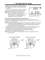
Setting a Standard Speed
• Ensure that the locking slider is in the unlocked (right) position.
• Make sure the LCD display is in mode 1 (black bar is visible).
• Push the SEL button to cycle through the available standard
speeds (23.976, 24, 25, 29.97 and 30 fps). Each speed will
flash for approximately 3 seconds.
• While a speed is flashing, push the SET button to set it.
Note: Set the NORM - PS/CCU switch to NORM to run the
camera at the set standard speed.
Setting a Programmable Speed
• Ensure that the locking slider is in the unlocked (right) position.
• Push the MODE button once to change from mode 1 to
mode 2 ("PS" - programmable speed).
• Press the SEL button to select one digit after the other. A
selected digit will blink. Press the SET button to increment the
value of a flashing digit by one. Repeat this procedure for all
digits that need to be changed. A final confirmation of the set
speed is not necessary.
Speeds below 100 fps are shown in the display with three
digits past the decimal point. Speeds of 100 fps and above
are shown with two digits past the decimal point.
Note: Set the NORM - PS/CCU switch to PS/CCU to run the
camera at the set programmable speed.
Setting the Camera to run in Reverse
• Ensure that the locking slider is in the unlocked (right) position.
• Push the MODE button once to change from mode 1 to
mode 2.
• Press the SEL button once. "cd" (camera direction) will blink.
• Push the SET button for three seconds. When the camera is set
to run in reverse, the letter ”R” appears in the display.
Note: The ”R” symbol is the only indication that the camera
will run in reverse. Pay close attention!
Note: Camera direction will be set to reverse for the standard
speeds (NORM) and for the programmable speeds (PS).
LCD display in mode 1.
Current frame rate set at 24.000 fps.
LCD display in mode 2.
Current frame rate set at 150.00 fps.
LCD display in mode 2.
Current frame rate set at reverse
150.00 fps.
Arriflex 435 Quick Guide, 4/99, Page 12
7. Changing Shutter Angle
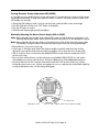
Checking the Mirror Shutter Angle (435 & 435ES)
• Push the PHASE button for about 5 seconds while the camera
is in standby.
• The top line of the LCD display will show the open angle of the
mirror shutter. The bottom line will show the battery voltage.
Note: The 435ES shutter angle is also visible in mode 7.
Note: To always view the 435ES shutter angle in mode 1:
- Make sure the display is in mode 1 (black bar visible).
- Push the SEL button until the upper line flashes.
- Push the SET button to switch the upper line between
the footage counter and the shutter angle.
LCD display with PHASE button pressed.
Open mirror shutter angle (22.5°) and
battery voltage (24.2 V) are visible.
Electronically Changing the Mirror Shutter Angle (435ES)
The open mirror shutter angle of the 435ES can be set in 0.1° increments by the LCC, RCU or CCU.
The following shutter angles can be set directly on the camera: 11.2°, 22.5°, 30°, 45°, 60°, 75°, 90°, 105°,
120°, 135°, 144°, 172.8° and 180°.
Note: Before electronically adjusting the shutter, make sure that the shutter is unlocked. Check with a 2 mm
hex driver that the shutter lock (labeled CATCH) is in the LOOSE position (all the way counter-clock
wise). The locking tab should not be visible (see graphic). Attempting to electronically adjust the
shutter while it is locked can damage the camera!
• Change the LCD display to mode 7 by pushing the MODE button six times. The display should show the
shutter symbol and the current shutter angle in the top line, and the fps rate in the bottom line.
If the display shows ”OFF”, the electronic adjustment of the shutter is deactivated.
• Press the SEL button repeatedly until the desired shutter angle flashes in the display.
• Press the SET button to confirm the flashing shutter angle.
Note: If a flashing shutter angle is not confirmed within 3 seconds, the shutter angle will revert to the
previously set value.
Mirror Shutter, Unlocked:
Mirror Shutter, Locked:
Locking tab
not visible
Shutter lock
Locking tab
visible
Shutter lock
Arriflex 435 Quick Guide, 4/99, Page 13
Turning Electronic Shutter Adjustment Off (435ES)
It is possible to turn the 435ES electronic shutter adjustment off. Once the electronic shutter is off, the shutter
can be adjusted manually. As long as the electronic shutter is turned off, the shutter symbol will blink in the
LCD display as a reminder.
• Change the LCD display to mode 7 until you see the shutter symbol and the current shutter angle.
• Press the SEL button until the word ”OFF” flashes in the display.
• Press the SET button to confirm.
• Set the desired shutter angle manually (see below).
Manually Adjusting the Mirror Shutter Angle (435 & 435ES)
Note: Before manually adjusting the shutter of the 435ES, make sure that the electronic adjustment is off.
Manually adjusting the 435ES shutter while the electronic adjustment is on can damage the camera!
Note: Before manually adjusting the shutter, turn the main power switch off and remove the power cable.
Accidentally running the camera while manually adjusting the shutter can cause great damage!
• Remove the lens or lens mount cavity cap.
• Use a finger on the black center area of the shutter assembly to carefully rotate the shutter until the
adjustment screw and the shutter lock are visible (see graphic). Do not touch the mirror shutter itself!
• With a 2 mm hex driver turn the shutter lock (labeled CATCH) counter clockwise towards the LOOSE
position until it stops.
• Now use the 2 mm hex driver to turn the adjustment screw (labeled OPEN/CLOSE). You will see the
shutter blade turn out from under the mirror. Position the blade at one of the labeled default positions.
• Turn the shutter lock with the 2 mm hex driver back towards the LOCK position (clockwise), until the
locking tab snaps into a cut out. If it does not engage into a cut out, reposition the shutter blade slightly by
turning the adjustment screw until the locking tab engages.
Shutter lock
Adjustment screw
Black center area of shutter assembly
Arriflex 435 Quick Guide, 4/99, Page 14
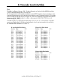
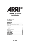
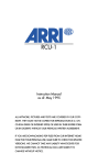
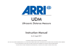
8. Timecode Sensitivity Table
Notes
This table is in effect as of January 1998. The latest information can be found in the ARRI Technical Note
P-1002 on the ARRI website at http://www.arri.com.
All the new generation Arriflex cameras are able to record SMPTE Timecode as a barcode on film. In order
to ensure the proper exposure of this barcode, the assistant has to set a "Timecode Sensitivity" (TCS) number.
The TCS number indicates the sensitivity of a given film stock to the wavelength of light produced by the LED
that exposes the film. The TCS number is set either on the magazine (535A, 535B, 16SR 3) or on the
camera directly (435, 435ES).
Timecode recording is possible at the standard speeds of 23.976, 24, 25, 29.97 and 30 fps. Some 535s
cannot record Timecode at 23.976, but can be modified to do so by any authorized Arri service facility.
No Timecode will be recorded if TCS is set to “0”.
35 mm Kodak Film Stocks
35 mm Fuji Film Stocks
Emulsion
Type
TCS
Emulsion
Type
TCS
5222
5224
5231
5239
5240
5245
5246
5248
5274
5277
5279
5287
5293
5294
5295
5296
5297
5298
5620
B/W Negative
B/W Reversal
B/W Negative
Color Reversal
Color Reversal
Color Negative
Color Negative
Color Negative
Color Negative
Color Negative
Color Negative
Color Negative
Color Negative
Color Negative
Color Negative
Color Negative
Color Negative
Color Negative
Color Negative
8
8
8
6
5
7
6
7
6
5
5
6
6
5
4
5
5
5
5
8510
8514
8520
8521
8530
8531
8550
8551
8560
8561
8570
8571
Color Negative
Color Negative
Color Negative
Color Negative
Color Negative
Color Negative
Color Negative
Color Negative
Color Negative
Color Negative
Color Negative
Color Negative
7
5
5
7
6
7
4
6
6
5
6
5
35 mm Agfa Film Stocks
Emulsion
Type
TCS
PAN 250
XT 100
XTR 250
XTS 400
B/W Negative
Color Negative
Color Negative
Color Negative
7
6
5
5
Arriflex 435 Quick Guide, 4/99, Page 15
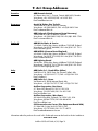
9. Arri Group Addresses
Canada:
ARRI Canada Limited
415 Horner Ave. Unit 11, Toronto, Ontario M8W 4W3, Canada
Voice phone: +416 255 3335, FAX: +416 255 3399
Email: [email protected]
Germany:
Arnold & Richter Cine Technik
Türkenstraße 89, D-80799 Munich, Germany
Voice phone: +49 (0)89 3809-0, FAX: +49 (0)89 3809-1244
Email: [email protected]
ARRI Leihpark (Film Equipment Rental Germany)
Türkenstraße 89, D-80799 Munich, Germany
Voice phone: +49 (0)89 3809-1240, FAX: +49 (0)89 3809-1798
Email: [email protected]
England:
ARRI GB Ltd Sales & Service
1-3 Airlinks, Spitfire Way, Heston, Middlesex, TW5 9NR, England
Voice phone: +44 (0)181 848 8881, FAX: +44 (0)181 561 1312
Email: [email protected]
ARRI MEDIA (Camera Rental England)
4-5 Airlinks, Spitfire Way, Heston, Middlesex, TW5 9NR, England
Voice phone: +44 (0)181 573 2255, FAX: +44 (0)181 756 0592
Email: [email protected]
ARRI Lighting Rental
20A Airlinks, Spitfire Way, Heston, Middlesex TW5 9NR, England
Voice phone: +44 (0)181 561 6700, FAX: +44 (0)181 569 2539
Email: [email protected]
Italy:
ARRI Italia S.r.l., Head Office (Milan)
Viale Edison 318, 20099 Sesto San Giovanni (Milan), Italy
Voice phone: +39 (0)2 262 271 75, FAX: +39 (0)2 242 1692
Email: [email protected]
ARRI Italia S.r.l., Rome
Via Placanica 95, 00040 Morena (Rome), Italy
Voice phone: +39 (0)6 726 707 97, FAX: +39 (0)6 723 1541
USA:
Arriflex Corporation, East Coast
617 Route 303, Blauvelt, NY 10913-1109, USA
Voice phone: 914-353-1400, FAX: 914-425-1250
Email: [email protected]
Arriflex Corporation, West Coast
600 North Victory Blvd., Burbank, CA 91502-1639, USA
Voice phone: 818-841-7070, FAX: 818-848-4028
Email: [email protected]
CSC Camera Service Center (Film Equipment Rental USA)
619 West 54th St, New York, NY 10019, USA
Voice phone: 212-757-0906, FAX: 212-713-0075
Email: [email protected]
Information about the products discussed in this Guide and more can be found on the Arri website at:
www.arri.com
Arriflex 435 Quick Guide, 4/99, Page 16