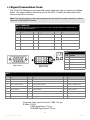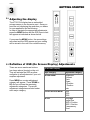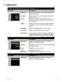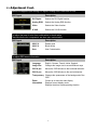
1
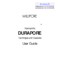
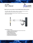
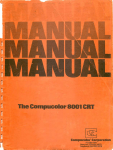
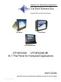
Solutions for Demanding Applications
VarTech Systems Inc.
Industrial CRT and Flat Panel Displays
Tray Mount
Flush Mount
In Honeywell Bezel
VT181CH4 · VT181CH4-IR
18.1” Flat Panel for Honeywell Applications
User’s Guide
Read these instructions completely before attempting to operate your new Color Display.
VT181CH4 User Guide
150-067
Table Of Contents
Section
Page
Section
Section 1
Section 4
Introduction
Touch screen
1.1 VT181CH4 Display Family
1
1.2 Product Safety Precautions
2
4.1 Touch Screen Introduction
Page
9
Section 5
Section 2
Troubleshooting Tips
10
Display Setup
2.1 Display Features
3
Section 6
2.2 Unpacking The Display
4
Cleaning & Maintenance
2.3 Included Parts
4
2.4 Connecting Your Display
4
2.5 Signal Connections
4-5
11
Section 7
Mechanical Drawings
Mounting Instructions
12
Section 3
Tray Mount Mechanical Drawing
13-14
Getting Started
Flush Mount Mechanical Drawing
15-16
3.1 Adjusting the Display
6
3.2 Adjustment Procedure
7-8
Section 8
Display Specifications
17
Section
1
1.1
INTRODUCTION
VT181CH Display Family
The VT181CH4 and VT181CH4-IR are part of a series of LCD replacement displays for the
Honeywell TDC Universal Stations (US) Classic Style furniture.
The VT181CH4 displays are offered as chassis tray mount models and as flush
mount models. The flush models mount to the Vartech Systems replacement console
bezels or the Honeywell replacement console bezel for systems which have been
upgraded to the 19" Sony monitor. The chassis tray models mount in the same method as
the original CRT displays.
The VT181CH4 and VT181CH4-IR displays are for stations that have GUS, PC Windows
based video. These displays replace the 20" Aydin or Intecolor CRT displays. The
VT181CH4-IR is supplied complete with a replacement console bezel and new flat IR touch
frame which is compatible with the original 20" touch frame being replaced.
1
VT181CH4 User Guide
150-067
1.2
Product Safety Precautions
⇒
Ensure that sufficient space is available around the display to provide the circulation
necessary for cooling.
⇒
Ensure that the ambient air temperature will not exceed the specified maximum
temperature.
⇒
Do not attempt to service this display yourself. The rear chassis has a seal so that non
qualified personal will not expose themselves to dangerous voltages or other risks.
⇒
To protect from electrical shock, unplug the display power supply from the console before
moving.
⇒
Do not expose the display to excessive heat.
⇒
Do not use this display near water.
⇒
Unplug the power supply from the console or unit if one of the following conditions exists.
⇒ Power cord or plug is damaged or frayed
⇒ Liquid is spilled into the display or the display is exposed to rain or water.
⇒ The display does not operate normally when the operating instructions are
followed.
⇒ The display has been dropped or the enclosure has been damaged.
⇒ The display exhibits a distinct change in performance, indicating a need for
service.
2
Section
DISPLAY SETUP
2
2.1 VT181CH4 Series Display Features
⇒
Capable of displaying unlimited colors in a continuous spectrum. The high contrast LCD
enhances the image with no geometric distortion.
⇒
The Displays come with a HD15 Input Connector.
⇒
The Displays are supplied with a remote membrane switch assembly that mounts to the front of
the console bezel for OSD controls.
⇒
The Display is supplied with an Anti-Reflective Screen.
⇒
The Display has an integrated 115/220VAC supply as standard on all models.
3
VT181CH4 User Guide
150-067
2.2 Unpacking and setting up your display
Your LCD monitor package will consist of the basic components listed below. Depending on the
display configuration, additional components are supplied.
2.3 What is included with your display
18.1” LCD Monitor
Accessory Kit: 2-Chassis stops; OSD Membrane Kit; Optional Chassis Brackets; IR touch
frame cable
⇒ Users Guide (Printed or on CD)
⇒
⇒
2.4 Connecting the Display
1. Connect all cables to the station first including the optional IR touch screen cable.
2. After connecting the cables between the LCD monitor and the station, plug the power cord
into the display.
3. Switch on the display power switch.
4. Reboot the station.
5. Your display should now operate showing the station video information.
Note: The displays are factory OSD adjusted for each configuration. However, additional OSD
adjustments may be required (See section 3).
2.5
Signal Connections
To avoid irregular operation and /or damage to the display, please insure correct video is being
supplied as shown on the following page.
4
2.5
Signal Connections Cont.
The VT181CH4 /Displays are provided with several video input type of connector as defined
below. The video connector that will be used is the HD15. Connect the video cable of the
station to the HD15 connector.
Note: The following figure is the view looking into the pin end of the male connector or solder
term end of the female connector.
HD15 Connector
The following table provides the pin numbers and corresponding pin assignments for
the HD-15 video connector.
Pin
Signal
Pin
Signal
Pin
Signal
1
Red Video
6
Red Video Ground
11
Not Used
2
Green Video
7
Green Video Ground
12
Bi-Directional Data
3
Blue Video
8
Blue Video Ground
13
Horizontal Sync
4
Not Used
9
No Connection
14
Vertical Sync
5
Return
10
Sync Ground
15
Data Clock (SCL)
C2
C1
Pin
C5
Signal
C1
Analog Red
16
24
C2
Analog Green
C3
Analog Blue
DVI-I Connector
(Digital / Analog)
C4
Analog H. Sync
C5
Analog Ground
1
8
9
17
HD15 Connector
DVI-I
C3
C4
DVI-I
Pin Signal
Pin
Signal
Pin Signal
1
T.M.D.S. Data2-
9
T.M.D.S. Data1-
17
T.M.D.S. Data0-
2
T.M.D.S. Data2+
10
T.M.D.S. Data1+
18
T.M.D.S. Data0+
3
T.M.D.S. Data2/4 Shield
11
T.M.D.S. Data1/3 Shield
19
T.M.D.S. Data0/5 Shield
4
T.M.D.S. Data4-
12
T.M.D.S. Data3-
20
T.M.D.S. Data5-
5
T.M.D.S. Data4+
13
T.M.D.S. Data3+
21
T.M.D.S. Data5+
6
DDC Clock
14
+5V Power
22
T.M.D.S. Clock Shield
7
DDC Data
15
Ground (return for +5V, H. Sync and V. Sync)
23
T.M.D.S. Clock+
8
Analog Vertical Sync
16
Hot Plug Detect
24
T.M.D.S. Clock-
Composite Video Input Connector: CVBS 1.0V p-p
S-Video: S-VHS
LUMA Signal Input 0.7V p-p
CHROMA Signal Input 0.7V p-p
5
VT181CH4 User Guide
150-067
Section
GETTING STARTED
3
3.1
Adjusting the display
The VT181CH4 display has an embedded
microprocessor in the converter card. Once you
have the unit displaying the resolution you desire
for your application do the following:
In order to navigate the appropriate adjustments,
press the MENU button and the OSD layout chart
will appear as indicated as shown below.
If you press the MENU button, the new settings
are saved and the OSD appear and your setting
will be stored in the unit’s non volatile memory.
3.2
Definition of OSD (On Screen Display) Adjustments
There are seven membrane buttons
(as shown above) located on the unit.
They will activate the OSD an allow
navigation to all adjustments if your unit
requires adjustment.
Press MENU an a major adjustment
category will appear. Press DOWN or
UP and you will see the remaining
adjustment categories. The actual
adjustment categories are listed under
each major category.
On Screen Display
Major Category
Adjustment Category
ADJUSTMENT
Brightness
Contrast
Clock
Phase
H Position
V Position
Auto
COLOR ADJUSTMENT
User
6500
9300
SETUP
Language
Image Size
OSD H Position
OSD V Position
Transparency
Zoom
6
3.3
Adjustment
To adjust the brightness and contrast of the screen
OSD Agent
Description
Brightness
Adjusts the brightness of video without affecting PC
RGB’s brightness
Contrast
Adjusts the contrast of video without affecting PC
RGB’s contrast
Clock
Removes the noises. When frequency value is
wrong, the image has horizontal lines especially in
1 dot on and off.
Phase
Removes the noises. When phase value is wrong,
the image has vertical lines especially in 1 dot on
and off.
H Position
Adjusts the horizontal position of the image.
V Position
Adjusts the vertical position of the image.
Auto Adjust
“Auto adjustment” allows the monitor to self-adjust
to the incoming video signal. The values of phase,
frequency and position are adjusted automatically.
This function is active if you select an input source other than PC. (DVD, VCR, TV)
OSD Agent
Description
Brightness
Adjusts the brightness of video or TV without
affecting PC RGB’s brightness.
Contrast
Adjusts the contrast of video or TV without affecting
PC RGB’s contrast.
Color
Changes the richness of color.
Tint
Changes the tone of color.
Sharpness
Adjusts the sharpness of video or TV image.
This function is active if you select a digital DVI input source.
OSD Agent
Description
Brightness
Adjusts the brightness of video or TV without
affecting PC RGB’s Brightness.
7
VT181CH4 User Guide
150-067
3.3
Adjustment Cont.
Selects the applied input among DVI digital, Analog RGB, Video and S-VHS
OSD Agent
Description
DVI Digital
Selects the DVI Digital function.
Analog RGB
Selects the Analog RGB function.
Video
Selects the Video function.
S-VHS
Selects the S-VHS function.
To adjust the tone of color from redish white to bluish white.
The individual color components are also user customizable.
OSD Agent
Description
6500º K
Redish white
9300º K
Bluish White
User
User Customizable
To adjust OSD menu information
OSD Agent
Description
Language
English, German, French, Italian, Spanish
Image Size
Changes the image size in several different ways
OSD H pos
Moves the OSD Window to the horizontal direction.
OSD V pos
Moves the OSD Window to the vertical direction.
Transparency Changes the opaqueness of the background of the
OSD
Zoom
Closes up or down the main display
Information
Displays current display mode.
Displays the driver board operating duration.
8
Section
4
4.1
TOUCH SCREEN
Touch Screen Introduction
The VT181CH4-IR is supplied with a new flat IR touch frame which is compatible with the
original monitor IR touch frame.
Connect the DB9 cable connector to the DB9 connector on the new IR touch frame.
Connect the 10 position (2x5) connector to J1 on the I/O Adapter board.
Connect the 7 position (1x7) connector to J4 of the I/O Adapter board.
It will be necessary to reboot the system for the new touch frame to be activated.
9
VT181CH4 User Guide
150-067
Section
5
TROUBLESHOOTING
Troubleshooting Tips
Problem
Troubleshooting Tip
No image on display screen
1. Check that the power cord of the station has been connected to
the display.
2. Check that the power switch of the Display has been turned to
the on position.
3. Check that the Video (Signal) Cable from the Display has been
securely and correctly connected to the video source.
Abnormal image
1. Check that the correct display model is being used for the
station. VT181CH4 for GUS Stations (PC Windows Based)
2. Check that the Video (Signal) Cable from the Display has been
securely and correctly connected to the connectors on the
video source.
Colors of image on screen
are abnormal
1. Check that the Video (Signal) Cable from the display has been
securely and correctly connected to the connectors on the
video source.
2. Adjust the OSD control for correct color balance.
Disturbances on Screen
1. OSD adjustment is incorrect. Please consult section 3 for OSD
screen adjustment procedures.
10
Section
6
CLEANING AND MAINTANENCE
Cleaning
Occasionally clean the display panel and cabinet with a soft cloth dampened (not soaked) with a
mild (non-abrasive) glass cleaner. Keep turning a fresh side of the cloth toward the screen surface to
avoid scratching it with accumulated grit.
Note:
The solvent should be applied only to the cloth, and not directly on the monitor screen.
Do not use paper products as they may scratch the surface. To minimize the risk of abrasion, allow
the screen to stand dry.
Special care should be taken when cleaning a touch screen or polycarbonate shield that is installed
over the screen. Abrasive and certain chemical cleaners can easily damage the surface.
Never use alcoholic or ammoniac cleaners to clean the polycarbonate shield or a touch screen.
Note:
For best results cleaning a monitor with the optional antireflective tempered glass display shield, a
solution of denatured alcohol is recommended to thoroughly clean the display.
Other Maintenance
Qualified service personnel should perform all maintenance, except for the power cord replacement
described above.
11
VT181CH4 User Guide
150-067
Section
7
MOUNTING INSTRUCTIONS
Mechanical Drawings
Model
Description
Page(s)
VT181CH4
Tray Mount
13-14
VT181CH4
Flush Mount
15-16
7.1
Mounting Procedure - Tray Mount
1. Remove the original CRT display monitor. Keep the two "L" shaped brackets.
These brackets will be used to mount the flat display.
Included with the display are a set of brackets for both upper and lower tier mounting.
2. Remove the original front console bezel and 20" curved IR touch frame.
3. Install the new replacement console bezel with the original four screws.
The new console bezel is complete with the new flat IR touch frame.
4. Connect the new touch cable per section 4.1
5. Mount the display to either the lower tier slide tray or the upper tier fixed tray using the supplied
brackets. Position the display to the rear of the flat IR touch frame. For lower tier applications,
replace the tray stop bolts with the longer supplied stop tubes and bolts and secure.
6. Connect the membrane extension cable to the membrane tab that projects through the console bezel.
7. Connect the video cable per section 2.5
8. Connect the power cord to the display and select the power switch to ON
9. Turn on the station main power switch and boot the system
10. Make any OSD adjustments if required per section 3.1
7.2
Mounting Procedure - Flush Mount
1. Remove the original CRT display monitor.
2. Remove the original front console bezel and 20" curved IR touch frame.
3. Install the new replacement console bezel with the original four screws.
The new console bezel is complete with the new flat IR touch frame.
4. Connect the new touch cable per section 4.1
5. Mount the display to the rear of the lower tier or upper tier replacement console bezel using the
supplied screws.
6. Connect the membrane extension cable to the membrane tab that projects through the console bezel.
7. Connect the video cable per section 2.5
8. Connect the power cord to the display and select the power switch to ON
9. Turn on the station main power switch and boot the system
10. Make any OSD adjustments if required per section 3.1
Note:
For display upgrade only when replacing the flat screen Sony monitor, omit step 2, step 3, and step 4.
12
Section
8
SPECIFICATIONS
ENGINEERING SPECIFICATIONS
Panel Size
18.1”
Type
TFT Bright Active matrix
AR / AG Protective Faceplate
Resolution Capabilities
VGA to SXGA
Pixel Pitch
0.2805mm
Active Display Area
14.315” x 11.308/”
359.04mm x 287.23mm
Viewing Angle (Left/Right)
80/80º
Viewing Angle (Up/Down)
80/80º
Contrast Ratio
350:1
Brightness
300 Nits
Response Time
TR = 15ms typical
TF = 15ms typical
Back Lights
Cold Cathode 50,000 Hrs. Half Life
Video Connector
Colors Supported
Video Input
Sync
HD15(F) (This connector for VT181CH4 usage)
DVI-I 29Pin connector (Digital/Analog)
Composite Video (CVSC)
S-Video (S-VHS)
16.7M
RGB Analog (0.7V p-p / 75ohm) , Digital
CVBS (1.0V p-p)
S-VHS, luma/chroma (.7V p-p / 75ohm)
Separate H&V, Combined,
SOG (Sync On Green), Digital
Input Voltage
AC 100-240V 50/60Hz 1.0A
Power consumption
Normal: 55Watts DPMS: < 3Watts
Operating Temperature
0 to 50ºC
Storage Temperature
-20 to 60ºC
Operating Humidity
0 to 95%NC
Storage Humidity
0 to 95%NC
Operating Altitude
Up to 10,000 ft
Storage Altitude
Up to 40,000 ft
17
VT181CH4 User Guide
150-067
VARTECH SYSTEMS
HEADQUARTERS
11529 Sun Belt Ct.
Baton Rouge, Louisiana 70809
Toll-Free: 800.223.8050
International Phone: 001.225.298.0300
Fax: 225.297.2440
E-mail: [email protected]
www.vartechsystems.com
150-067-002
4.16.04