1
"( I. It II
..,
"
~*I-
1
1ft
-t
o
q
'"
~LD"'"
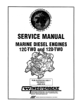
SERVICE MANUAL
71 B-FOUR / 71 C-FOUR
MARINE DIESEL ENGINES
and
20.0KW-60Hz/16.0KW-50Hz BED
20.0KW-60Hz/16.0KW-50Hz BEDA
MARINE DIESEL GENERATORS
SINGLE AND THREE PHASE
PUBLICATION NO. 43317
FIRST EDITION I FEBRUARY 1998
l"'" 'WESTERBEKE
j
..
WESTERBEKE CORPORATION' MYLES STANDISH INDUSTRIAL PARK
150 JOHN HANCOCK ROAD' TAUNTON MA 02780-7319' TEL. 1-508-823-7677
FAX 1-508-884-9688' WEBSITE: Www.WESTERBEKECOM
---
..
~"fI!A Member National Marine Manufacturers Association
CALIFORNIA
PROPOSITION 65 WARNING
Diesel engine exhaust and some
of its constituents are known to
the State of California to cause
cancer, birth defects, and other
reproductive harm.
A WARNING
Exhaust gasses contain Carbon Monoxide, an odorless and colorless gas. Carbon Monoxide is poisonous and can cause
unconsciousness and death. Symptoms of Carbon Monoxide
exposure can Include:
-Dizziness
- Throbbing in Temples
-Nausea
- Muscular Twitching
-Headache
- Vomiting
- WfIlIkness and Sleepiness -Inability to Think Coherently
IF YOU OR ANYONE ELSE EXPERIENCE ANY OF THESE SYMPTOMS,
SET OUT INTO THE FRESH AIR IMMEDIATELY. " symptoms persist,
seek medical attention. Shut down the unit and do not restart
until It has been Inspected and repaired.
SAFETY INSTRUCTIONS
INTRODUCTION
PREVENT BURNS - FIRE
Read this safety manual carefuUy. Most accidents are
caused by failure to foUow fundamental rules and precautions. Know when dangerous conditions exist and toke the
necessary precautions to protect yourself, your personnel,
and your machinery.
The foUowing safety instructions are in compliance with
the American Boat and Yacht Council (ABYC) standards.
A WARNING: Fire can cause Injury
• Prevent flash fires. Do not smoke or permit flames or
sparks to occur near the carburetor, fuel line, filter, fuel
pump, or other potential sources of spilled fuel or fuel
vapors. Use a suitable container to catch all fuel when
removing the fuel line, carburetor, or fuel filters.
PREVENT ELECTRIC SHOCK
• Do not operate with a Coast Guard Approved flame
arrester removed. Backfire can cause severe injury or
death.
A WARNING: Do not touch AC elBCtrlcal CDIIIIBCIIons
while engine is IUnningl Of when connected to shore
power. Lethal voltage is present at these connections!
• Do not operate with the air cleaner/silencer removed.
Backfire can cause severe injury or death.
• Do not smoke or permit flames or sparks to occur near the
fuel system. Keep the compartment and the engine/generator clean and free of debris to minimize the chances of
fire. Wipe up all spilled fuel and engine oil.
• Do not operate this machinery without electrical
enclosures and covers in place.
• Shut off electrical power before accessing electrical
equipment.
• Be aware -
diesel fuel will burn.
PREVENT BURNS - EXPLOSION
• Use insulated mats whenever working on electrical
equipment.
A WARNING: Explosions from fuel vapors can cause
• Make sure your clothing and skin are dry, not damp
(particularly shoes) when handling electrical equipment.
Injury Of death!
• Remove wristwatch and all jewelry when working on
electrical equipment.
• Follow re-fueling safety instructions. Keep the vessel's
hatches closed when fueling. Open and ventilate cabin
after fueling. Check below for fumes/vapor before running the blower. Run the blower for four minutes before
starting your engine.
• Do not connect utility shore power to vessel's AC
circuits, except through a ship-to-shore double throw
transfer switch. Damage to vessel's AC generator may
result if this procedure is not followed.
• All fuel vapors are highly explosive. Use extreme care when
handling and storing fuels. Store fuel in a well-ventilated
area away from spark-producing equipment and out of the
reach of children.
• Electrical shock results from handling a charged capacitor.
Discharge capacitor by shorting terminals together.
PREVENT BURNS - HOT ENGINE
A WARNING: Do not touch hot engine parts
Of death!
• Do not fill the fuel tank(s) while the engine is running.
• Shut off the fuel service valve at the engine when servicing
the fuel system. Take care in catching any fuel that might
spill. DO NOT allow any smoking, open flames, or other
sources of fire near the fuel system or engine when servicing. Ensure proper ventilation exists when servicing the
fuel system.
Of
exhaust system components. A IUnnlng engine gets
very hot!
• Always check the engine coolant level at the coolant
recovery tank.
• Do not alter or modify the fuel system.
• Be sure all fuel supplies have a positive shutoff valve.
A WARNING: Steam can cause injury Of death!
• Be certain fuel line fittings are adequately tightened and
free of leaks.
• In case of an engine overheat, allow the engine to cool
before touching the engine or checking the coolant.
• Make sure a fire extinguisher is installed nearby and is
properly maintained. Be familiar with its proper use.
Extinguishers rated ABC by the NFPA are appropriate
for all applications encountered in this environment.
i
SAFETY INSTRUCTIONS
ACCIDENTAL STARTING
TOXIC EXHAUST GASES
A WARNING: Accidental starting can cause Injury
A WARNING: carbon monoxide (CO) Is a deadly gas!
01 death!
• Ensure that the exhaust system is adequate to expel gases
discharged from the engine. Check the exhaust system
regularly for leaks and make sure the exhaust manifolds
are securely attached and no warping exists. Pay close
attention to the manifold, water injection elbow, and
exhaust pipe nipple.
• Be sure the unit and its surroundings are well ventilated.
• In addition to routine inspection of the exhaust system,
install a carbon monoxide detector. Consult your boat
builder or dealer for installation of approved detectors.
• For additional information refer to ABYC T-22 (educational information on Carbon Monoxide).
• Disconnect the battery cables before servicing the engine!
generator. Remove the negative lead first and reconnect
it last.
• Make certain all personnel are clear of the engine before
starting.
• Make certain all covers, guards, and hatches are reinstalled before starting the engine.
BATTERY EXPLOSION
A WARNING: Battery explosion can cause Injury
01 death!
A WARNING: ca,bon monoxide (CO) Is an Inlllsible
• Do not smoke or allow an open flame near the battery
being serviced. Lead acid batteries emit hydrogen, a
highly explosive gas, which can be ignited by electrical
arcing or by lit tobacco products. Shut off all electrical
equipment in the vicinity to prevent electrical arcing during servicing.
• Never connect the negative (-) battery cable to the positive (+) connection terminal of the starter solenoid. Do not
test the battery condition by shorting the terminals
together. Sparks could ignite battery gases or fuel vapors.
Ventilate any compartment containing batteries to prevent
accumulation of explosive gases. To avoid sparks, do not
disturb the battery charger connections while the battery is
being charged.
• Avoid contacting the terminals with tools, etc., to prevent
burns or sparks that could cause an explosion. Remove
wristwatch, rings, and any other jewelry before handling
the battery.
• Always turn the battery charger off before disconnecting
the battery connections. Remove the negative lead first
and reconnect it last when disconnecting the battery.
odorless gas. Inhalation ploduces Du-lIke symptoms,
nausea 01 death!
• Do not use copper tubing in diesel exhaust systems. Diesel
fumes can rapidly destroy copper tubing in exhaust systems. Exhaust sulfur causes rapid deterioration of copper
tubing resulting in exhaust/water leakage.
• Do not install exhaust outlet where exhaust can be drawn
through portholes, vents, or air conditioners. If the engine
exhaust discharge outlet is near the waterline, water could
enter the exhaust discharge outlet and close or restrict the
flow of exhaust. Avoid overloading the craft.
• Although diesel engine exhaust gases are not as toxic as
exhaust fumes from gasoline engines, carbon monoxide
gas is present in diesel exhaust fumes. Some of the symptoms or signs of carbon monoxide inhalation or poisoning
are:
Vomiting
Dizziness
Throbbing in temples
Muscular twitching
Intense headache
Weakness and sleepiness
BATTERY ACID
A WARNING: Sulfuric acid In battelles can cause
severe Injury 01 death!
AVOID MOVING PARTS
• When servicing the battery or checking the electrolyte
level, wear rubber gloves, a rubber apron, and eye protection. Batteries contain sulfuric acid which is destructive. If
it comes in contact with your skin, wash it off at once
with water. Acid may splash on the skin or into the eyes
inadvertently when removing electrolyte caps.
A WARNING: Rotating parts can cause Injury
01 death!
• Do not service the engine while it is running. If a situation
arises in which it is absolutely necessary to make operating adjustments, use extreme care to avoid touching moving parts and hot exhaust system components.
Engines & Generators
ii
SAFETY INSTRUCTIONS
ABYC, NFPA AND USCG PUBLICATIONS FOR
INSTALLING DIESEL ENGINES
• Do not wear loose clothing or jewelry when servicing
equipment; avoid wearing loose jackets, shirts, sleeves,
rings, necklaces or bracelets that could be caught in
moving parts.
Read the following ABYC, NFPA and USCG publications
for safety codes and standards. Follow their recommendations when installing your UNIVERSAL engine
ABYC (American Boat and Yacht Council)
"Safety Standards for Small Craft"
• Make sure all attaching hardware is properly tightened.
Keep protective shields and guards in their respective
places at all times.
• Do not check fluid levels or the drive belt's tension while
the engine is operating.
Order From:
ABYC
15 East 26th Street
New York, NY 10010
NFPA (National Fire Protection Association)
"Fire Protection Standard for Motor Craft"
• Stay clear of the drive shaft and the transmission coupling
when the engine is running; hair and clothing can easily
be caught in these rotating parts.
HAZARDOUS NOISE
Order From:
A WARNING: High noise legis can cause hearing
NFPA
loss!
1 Batterymarch Park
P.O. Box 9101
Quincy, MA 02269-9101
USCG (United States Coast Guard)
"USCG 33CFR183"
• Never operate an engine without its muffler installed.
• Do not run an engine with the air intake (silencer)
removed.
• Do not run engines for long periods with their enclosures
open.
Order From:
U.S. Government Printing Office
Washington, D.C. 20404
A WARNING: Do not wotk on machinery when you alB
mentally or physically Incapacitated by fatigue!
OPERATORS MANUAL
Many of the preceding safety tips and warnings are repeated
in your Operators Manual along with other cautions and
notes to highlight critical information. Read your manual
carefully, maintain your equipment, and follow all safety
procedures.
ENGINE INSTALLATIONS
Preparations to install an engine should begin with a thorough examination of the American Boat and Yacht Council's
(ABYC) standards. These standards are a combination of
sources including the USCG and the NFPA.
Sections of the ABYC standards of particular interest are:
B-2 Ventilation
P-l Exhaust systems
P-4 Inboard engines
E-9 DC Electrical systems
All installations must comply with the Federal Code of
Regulations (FCR).
iii
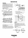
INSTALLATION
When installing WESTERBEKE engines and generators it is important that strict
attention be paid to the following information:
CODES AND REGULATIONS
Strict federal regulations, ABYC guidelines, and safety codes must be complied with
when installing engines and generators in a marine environment.
SIPHON-BREAK
For installations where the exhaust manifold/water injected exhaust elbow is below
the vessel's waterline, provisions must be made to install a siphon-break in the raw
water supply hose to the exhaust elbow. This hose must be looped a minimum of 18"
above the vessel's waterline. Failure to use a siphon-break when the exhaust
manifold injection port is at or below the load waterline will result in raw water
damage to the engine and possible flooding of the boat.
EXHAUST SYSTEM
The exhaust hose must be certified for marine use. The system must be designed to
prevent water from entering the exhaust under any sea conditions and at any angle
of the vessels hull.
'A detailed 40 page Marine Installation Manual covering gasoline and diesel,
engines and generators, is available from your WESTERBEKE dealer.
Engines & Generators
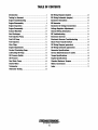
TABLE OF CONTENTS
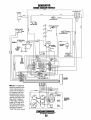
DC Wiring Diagram (engine) .................................... .48
DC Wiring Schematic (engine) ................................ .49
Generator Information ..............................................50
BE Generator .............................................................51
Generator AC Voltage Connections .. .......................52
Voltage Regulator Adjustments ...............................54
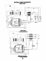
Internal Wiring Schematics ...................................... 55
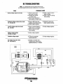
BE Troubleshooting ...................................................56
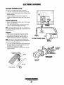
Electronic Governor ..................................................57
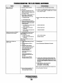
Electronic Governor Troubleshooting ...................... 58
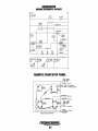
Shore Power Transfer Switch ................................... 59
DC Wiring Diagram (generator) ................................60
DC Wiring Schematic (generator) ............................61
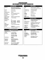
Generator Specifications ..........................................62
Service Data/Tolerances &Limits ............................64
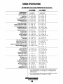
Torque Specifications ...............................................68
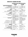
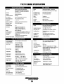
Engine Specifications ...............................................69
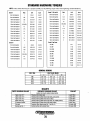
Standard Hardware Torques .....................................70
Metric Conversions ..................................................71
Index ..........................................................................72
Introduction ................................................................2
Testing for Overhaul ...................................................3
Engine Troubleshooting ............................................. .4
Engine Disassembly ....................................................8
Engine Inspection .....................................................13
Engine Reassembly ...................................................23
Exhaust Manifold ......................................................29
Heat Exchanger .........................................................29
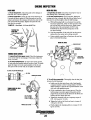
Fuel Injection Pump .................................................30
Fuel Lift Pump ..........................................................31
Fuel Injectors .. ................................................-.......... 32
Glow Plugs ................................................................34
Engine Adjustments ..................................................35
Coolant Circulating Pump ........................................37
Lubricating Oil Pump ............................................... .38
Oil Pressure Switch ..................................................39
Oil Pressure ..............................................................39
Raw Water Pump .......................................................40
Starter Motor ............................................................41
Tachometer ...............................................................45
Alternator Testing .................................................... .46
Engines & Generators
1
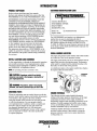
INTRODUCTION
CUSTOMER IDENTIFICATION CARD
PRODUCT SOFTWARE
Product software (tech data, parts lists, manuals,
brochures and catalogs) provided from sources other than
WESTERBEKE are not within WESTERBEKE'S control.
/..-v-IWES I ERBEKE
I
.
WESTERBEKE CANNOT BE RESPONSIBLE FOR THE
CONTENT OF SUCH SOFTWARE, MAKES NO
WARRANTIES OR REPRESENTATIONS WITH RESPECT
THERETO, INCLUDING ACCURACY, TIMELINESS OR
COMPlETENESS THEREOF AND WILL IN NO EVENT
BE UABLE FOR ANY TYPE OF DAMAGE OR INJURY
INCURRED IN CONNECTION WITH OR ARISING OUT
OF THE FURNISHING OR USE OF SUCH SOFTWARE.
Customer Identification
WESTERBEKE OWNER
MAIN STREET
HOMETOWN, USA
Model71C
Expires 4/4/98
WESTERBEKE customers should also keep in mind the
time span between printings of WESTERBEKE product
software and the unavoidable existence of earlier
WESTERBEKE manuals. Product software provided with
WESTERBEKE products, whether from WESTERBEKE
or other suppliers, must not and cannot be relied upon
exclusively as the definitive authority on the respective
product. It not only makes good sense but is imperative
that appropriate representatives ofWESTERBEKE or the
supplier in question be consulted to determine the accuracy
and currentness of the product software being consulted by
the customer.
Ser. #UOOOO-D702
The WESTERBEKE serial number is an alphanumeric
number that can assist in determining the date of
manufacture of your WESTERBEKE engine/generator. The
first character indicates the decade (A=1960s, B=1970s,
C=1980s, 0=1990s), the second character represents the year
in the decade, and the fourth and fifth number represents the
month of manufacture.
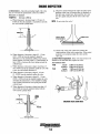
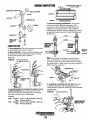
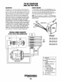
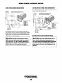
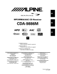
SERIAL NUMBER LOCATION
The engine and generator serial numbers and model numbers
are located on a decal on the generator housing.
NOTES, CAUTIONS AND WARNINGS
The engine serial number can also be found stamped into the
engine block just above the injection pump. The generator
serial number is stamped into the generator housing on the
flat surface on the left side of the generator..
As this manual takes you through the disassembly, inspection
and assembly procedure of your engine/generator, critical
information will be highlighted by NOTES, CAUTIONS,
and WARNINGS. An explanation follows:
An identification plate on the engine manifold also displays
the engine model and serial number.
NOTE: An operating procedure essential to note.
A CAUTION: Procedures, which if not strictly
GENERATOR
10 DECAL
obselVt1d, can result in the damage or destruct/on of
your engine/generator.
ENGINE
SERIAL
NUMBER
A WARNING: Procedures, whIch if not properly
followed, can result in personal injury or loss of life.
ORDERING PARTS
Whenever replacement parts are needed, always provide the
generator model number, engine serial number, and generator
serial number as they appear on the silver and black
name-plate located on the generator end. You must provide
us with this information so we may properly identify
your engine/generator. In addition, include a complete part
description and part number for each part needed (see
the separately furnished Parts List). Also insist upon
WESTERBEKE packaged parts because will fit or generic
parts are frequently not made to the same specifications
as original equipment.
The following sections contain detailed information
relating to the proper operation characteristics of the major
components and systems of the engine. Included are
disassembly, inspection and reassembly instructions for the
guidance of suitable equipped and staffed marine engine
service and rebuilding facilities. The necessary procedures
should be undertaken only by such facilities.
Additional detailed information and specifications are
provided in other sections of this manual, covering the
generator, alternator, starter motor, engine adjustments,
cooling pumps, etc.
Engines & Generators
2
TESTING FOR OVERHAUL
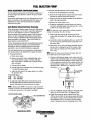
HOW TO DETERMINE ENGINE OVERHAUL PERIOD
Precautions for Disassembly and Reassembly
Cause of Low Compression
When servicing an engine, keep in mind the following
precautions.
Generally, the time at which an engine should be overhauled
is determined by various conditions such as lowered engine
power output, decreased compression pressure, and increased
fuel and oil consumption. The lowered engine power output,
in the case of diesel engines, is not necessarily due to trouble
with the engine itself, but is sometimes caused by injector
nozzle wear or injection pump wear. It is most reasonable to
judge by a decrease in compression pressure. The decrease
in compression pressure is caused by many factors. It is,
therefore, necessary to determine a cause or causes on the
basis of data produced by periodic inspection and
maintenance. Oil analysis on a seasonal basis is a good
means of monitoring engine internal wear. When caused
by worn cylinders or piston rings, the following symptoms
will occur:
1 Low engine power output
2 Increased fuel consumption
3 Increased oil consumption
4 Hard engine starting
5 Noisy engine operation
Disassembly
1. Before disassembly and cleaning, carefully check for
defects which cannot be found after disassembly and
cleaning.
2. Drain water, fuel and oil before disassembly.
3. Clean or wash the engine exterior.
4. Do not remove or disassemble the parts that require no
disassembly.
5. Perform disassembly in a proper order using proper tools.
Keep disassembled parts in order. Apply oil when necessary. Take special care to keep the fuel system parts from
intrusion of dust and dirt.
Reassembly
1. Clean or wash the parts. Apply oil on surfaces where
needed or specified.
2. Carefully check gaskets, packings and oil seals even
if checking is not specified. Replace with new ones
if defective.
These symptoms often appear together. Symptoms (2) and
(4) can result also from excessive fuel injection, improper
injection timing, and wear of plugs and nozzles. They are
caused also by defective electrical devices such as the battery,
alternator, starter and glow plugs. Therefore it is desirable
to judge the optimum engine overhaul time by the lowered
compression pressure caused by worn cylinders and pistons
plus increased oil consumption. In diesel engines,
satisfactory combustion is obtained only under sufficient
compression pressure. If an engine lacks compression
pressure, incomplete combustion of fuel will take place even
if other parts of the engine are operating properly. To
determine the period of engine overhaul, it is important to
measure the engine compression pressure regularly. At the
same time, the engine speed at which the measurement of
compression pressure is made should be checked because the
compression pressure varies with engine rpm. The engine
rpm can be measured at the front end of the crankshaft.
3. Be sure to install components in proper directions and
positions. (pay attention to dowel pins, mating marks and
specified directions.) Where tightening torque is not
specified, tighten evenly to an ordinary torque. Apply
sealant where specified.
4. After completion of reassembly, recheck for any
abnormalities. Prepare for starting the engine, and idle
the engine sufficiently for a test run.
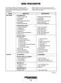
ENGINE TROUBLESHOOTING
The following ENGINE TROUBLESHOOTING section may
be of assistance in determining the need for planning and
engine overhaul.
NOTE: To test engine compression see the
SERVICE MANUAL
ENGINE ADJUSTMENT section of this manual.
The engine block of the 7lC-FOUR differs from it's
predecessor, the 71B-FOUR, with variations in service data
(tolerances, limits and torques). In this service manual 71 B
or 71 C designates this service data and a small 718 or 71C
will identify the artwork. Components that are common to
both engines such as the Raw Water Pump will have no
designation.
The 71B-FOUR engine powers the 20.0KW BED generator.
The 7lC-FOUR engine powers the 20.0KW BEDA generator.
OVERHAUL CONDITIONS
Compression pressure tends to increase a little in a new
engine until piston rings and valve seats have been broken in.
Thereafter, it decreases gradually with the progress of wear
of these parts.
When decrease of compressiOll pressure reaches the repair
limit, the engine must be overhauled.
NOTE: Make certain the engine model has been correctly
identified, see SERIAL NUMBER LOCATION.
The engine requires overhaul when oil consumption is high,
blowby evident, and compression valves are at minimum or
below. Engine compression should be 30 kg/cm2,
427 psi at 200 rpm.
Engines & Generators
3
ENGINE TROUBLESHOOTING
Note: The engine s electrical system is protected by a 20ampere manual reset circuit breaker. The preheat solenoid is
mounted on the same bracket.
The following troubleshooting table describes certain
problems relating to engine service, the probable causes of
these problems, and the recommendations to overcome
these problems.
PROBLEM
HARD STARTING
LOW OUTPUT
VERIFICATION/REMEDY
PROBABLE CAUSE
LOW CRANKING SPEED
1. Engine oil viscosity too high.
2. Run-down battery.
3. Worn battery.
4. Battery terminals loosely connected.
5. Defective starter.
6.Defective main drive section.
1.
2.
3.
4.
5.
6.
Replace engine oil with less viscous oil.
Recharge battery.
Replace battery.
Clean terminals and correct cables.
Repair or replace starter.
Check clutch for disengagement.
DEFECTIVE INJECTION SYSTEM
1. Air trapped in fuel passage.
2. Clogged fuel filter.
3. Low injection pressure.
4. Inadequate spray.
5. Injection pump delivering insufficient fuel.
6. Injection too early.
1.
2.
3.
4.
5.
6.
Bleed air from fuel system.
Clean or replace filter.
Adjust injection pressure.
Clean or replace nozzle.
Repair or replace injection pump.
Adjust injection timing.
MAIN ENGINE TROUBLES
1. Low compression.
a. Incorrect valve clearance.
b. Inadequate contact of valve seat.
c. Valve stem seized.
d. Broken valve spring.
e. Compression leaks through cylinder head gasket.
f. Piston ring seized.
g. Worn piston ring and cylinder.
2. Burnt glow plug.
3. Faulty glow plug operation.
4. Incorrect governor lever position.
5. Governor spring out fo POSITION
2.
3.
4.
5.
LOW COMPRESSION
See HARD STARTING
INJECTION SYSTEM OUT OF ADJUSTMENT
1. Incorrect injection timing.
2. Insufficient injection.
3. Low injection pressure.
1. Adjust injection timing.
2. Repair or replace injection pump.
3. Check injection nozzle and adjust pressure.
INSUFFICIENT FUEL
1. Air trapped in fuel system.
2. Clogged filter.
3. Contaminated fuel tank.
INSUFFICIENT INTAKE AIR
1. Clogged air cleaner.
a.
b.
c.
d.
e.
Adjust valve clearance.
Lap valve.
Replace valve and valve guide.
Replace valve spring.
Replace gasket.
f. Replace piston and piston ring.
g. Overhaul engine.
Replace glow plug.
Correct lead wire connection.
Set lever to starting position.
Correct spring
1. Check and retighten connector.
2. Clean or replace filter.
3. Clean tank.
1. Clean or replace air cleaner.
(continued)
Engines & Generators
4
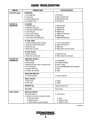
ENGINE TROUBLESHOOTING
LOW OUTPUT (cDnt.)
EXCESSIVE OIL
CONSUMPTION
VERIFICATION/REMEDY
PROBABLE CAUSE
PROBLEM
OVERHEATING
1. Low coolant level.
2. Loose V-belt.
3. Incorrect injection timing.
4. Low engine oil level.
1.
2.
3.
6.
OIL LEAKAGE
1. Defective oil seals.
2. Broken gear case gasket.
3. Loose gear case attaching bolts.
4. Loose drain plug.
5. Loose oil pipe connector.
6. Broken rocker cover gasket.
7. Loose rocker cover attaching bolts.
1. Replace oil seals.
2. Replace gasket.
3. Retighten bolts.
4. Retighten plug.
5. Retighten oil connections.
6. Replace gasket.
7. Retighten attaching bolts.
OIL LEVEL RISING
1. Incorrectly positioned piston ring gaps.
2. Displaced or twisted connecting rod.
3. Worn piston ring.
4. Worn piston or cylinder.
1.
2.
3.
4.
OIL LEVEL FALLING
. 1. Defective stem seal.
2. Worn valve and valve guide.
EXCESSIVE FUEL
CONSUMPTION
SMOKY EXHAUST
Add coolant.
Adjust or replace V-belt.
Adjust injection timing.
Add engine oil.
Correct ring gap positions.
Replace connecting rod.
Replace ring.
Replace piston and rebore cylinder.
1. Replace stem seal.
4. Replace a valve and valve guide.
ENGINE BODY TROUBLES
1. Noisy knocking.
2. Smoky exhaust.
3. Moving parts nearly seized or excessively worn.
4. Poor compression.
5. Improper valve timing.
6. Improper valve clearance.
1. See KNOCKING.
2. See SMOKY EXHAUST.
3. Repair or replace.
4. See LOW COMPRESSION; HARD STARTING.
5. Adjust.
6. Adjust.
INSUFFICIENT INTAKE AIR
1. Air intake obstructed.
1. Remove obstruction.
NOZZLE TROUBLES
1. Seized nozzle.
2. Worn nozzle.
1. Replace.
2. Replace.
IMPROPER FUEL
Replace with proper fuel.
FUEL LEAKS
Find fuel leaks.
WHITISH OR PURPLISH
1. Excessive engine oil.
2. Excessive rise of oil into combustion chamber.
a. Poor piston contact.
b. Seized piston ring ..
c. Excessive piston-to-cylinder clearance.
1. Correct oil level.
a. Check.
b. Replace or clean.
c. Replace or correct.
(continued)
Engines & Generators
5
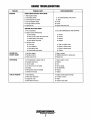
ENGINE TROUBLESHOOTING
PROBLEM
SMOKY EXHAUST (cont.)
ABNORMAL SOUND
OR NOISE
ROUGH OPERATION
PROBABLE CAUSE
VERIFICATION/REMEDY
WHITISH OR PURPLISH (cont.)
d. Worn valve stem and valve guide.
e. Low engine oil viscosity.
f. Excessive oil pressure.
3. Injection timing is too late.
4. Insufficient compression.
d. Replace.
e. Replace.
f. Correct.
3. Adjust.
4. See LOW COMPRESSION; HARD STARTING.
BLACKISH OR DARK GRAYISH
1. Engine body troubles.
a. Poor compression.
b. Improper valve clearance.
2. Insufficient intake air (air cleaner clogged).
3. Improper fuel.
a. See LOW COMPRESSION; HARD STARTING.
b. Adjust.
2. Clean air cleaner.
3. Replace with proper fuel.
CRANKSHAFT AND MAIN BEARING
1. Badly worn bearing.
2. Badly worn crankshaft.
3. Melted bearing.
1. Replace bearing and grind crankshaft.
2. Grind crankshaft.
3. Replace bearing and check lubrication system.
CONNECTING ROD AND CONNECTING ROD BEARING
1. Worn connecting rod big end bearing.
2. Worn crankpin.
3. Bent connecting rod.
1. Replace bearing.
2. Grind crankshaft.
3. Correct bend or replace.
PISTON, PISTON PIN, AND PISTON RING
1. Worn cylinder.
2. Worn piston pin.
3. Piston seized.
4. Piston seized and ring wom or damaged.
1.
2.
3.
4.
Rebore cylinder to oversize and replace piston.
Replace piston.
Replace piston and rebore cylinder.
Replace piston and rings.
VALVE MECHANISM
1. Worn camshaft.
2. Excessive valve clearance.
3. Worn timing gear.
4. Worn fan pulley bearing.
1.
2.
3.
4.
Replace.
Adjust.
Replace.
Replace.
INJECTION PUMP SYSTEM
1. Uneven injection.
2. Control rack malfunctioning.
3. Worn delivery valve.
4. Inadequate injection nozzle spray.
1.
2.
3.
4.
Adjust injection or replace parts.
Disassemble, check and correct injection pump.
Replace.
Replace injection nozzle.
GOVERNING SYSTEM
1. Governor lever malfunctioning.
2. Fatigued governor spring.
1. Check governor shaft and correct operation.
2. Replace.
(continued)
Engines & Generators
6
ENGINE TROUBLESHOOTING
PROBLEM
KNOCKING
PROBABLE CAUSE
VERIFICATION/REMEDY
ENGINE KNOCKS WITHOUT MUCH SMOKE
1. Main engine troubles.
a. Overheated cylinder.
a. See OVERHEATING; LOW OUTPUT.
h. Carbon deposits in cylinder.
2. Too early injection timing.
3. Too high injection pressure.
4. Improper fuel.
h. Clean.
2. Correct.
3. Correct.
4. Replace with proper fuel.
KNOCKING WITH DARK SMOKE
1. Poor compression.
1. See LOW COMPRESSION; HARD STARTING.
2. Injection pump malfunctioning.
a. Worn plunger.
h. Pinion is not in mesh with control rack.
c. Broken delivery valve spring.
d. Worn delivery valve seat.
3. Improper nozzle.
a. Poor spray.
h. Poor chattering.
c. After-injection drip.
d. Nozzle needle valve seized.
INTERMITTENT
EXHAUST SOUND
OVERHEATING
LOW OIL PRESSURE
a. Replace.
h. Correct.
c. Replace.
d. Replace.
a. Clean or replace nozzle.
h. Repair or replace nozzle.
c. Repair or replace nozzle.
d. Replace.
1. Fuel filter clogged.
1. Clean or replace.
2. Fuel pipe sucks air.
2. Retighten pipe jOints or replace pipe.
3. Water mixed in fuel
3. Replace fuel.
1. V-belt slackening or slippery with oil.
1. Adjust, replace or clean.
2. Damaged water pump.
2. Replace.
3. Lack of coolant.
4. Low oil level or poor oil quality.
5. Knocking.
6. Moving parts seized or damaged.
7. Defective thermostat.
3. Add.
4. Add or change.
5. See KNOCKING.
6. Replace.
7. Replace.
1. Worn Bearings.
1. Engine overhaul .replace bearings.
2. Relief valve malfunction.
2. Overhaul oil pump.
3. Clogged oil cooler.
4. Diesel dilution of the oil.
3. Repair.
4. Injection pump repair.
Engines & Generators
7
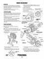
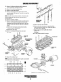
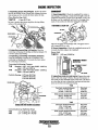
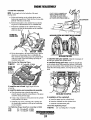
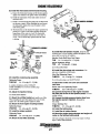
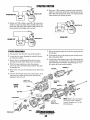
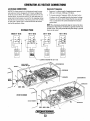
ENGINE DISASSEMBLY
GENERATOR
\
3. Remove engine heat exchanger and engine cooler. If possible, leave one end of each hose connection attached to
the part being r e m o v e d . '
4. Remove starter motor.
Disconnect the AC wiring, unplug the DC wiring harness
at the control panel and remove the speed sensor from the
bellhousing. Carefully support and then unbolt the generator
back end from the engine.
For generator maintenance and service, refer to the
GENERATOR SECTION of this manual.
S. Remove engine bellhousing.
6. Remove transmission damper plate.
ONE BOLT DEVIATES S'
.
FROM THE 6(], S-.€T UP ."
7. Remove flywheel.
PROPULSION ENGINE
Unplug the instrument panel wiring harness. Drain the transmission fluid and the transmission oil cooler hoses, Detach
the oil cooler hoses and unbolt the transmission from the
engine.
For transmission service and maintenance refer to your
transmission owners manual.
To rebuild a transmission contact your WESTERBEKE
dealer or your local marine transmission shop.
With the transmission or generator separated from the
engine, begin the following step by step procedure of engine
disassembly.
WHEN REMOVING
THE MOUNTING BOLTS - -____I4...~-IJ
LOCK THE FLYWHEEL
WITH A RING GEAR
BREAK TOOL
STARTER/SOLENOID f·
.
ENGINE DISASSEMBLY
Take the following precautions:
•. Clean the exterior of the engine of any deposits
of dirt and oil.
• Be careful not to damage the disassembled parts.
• Mount the engine on suitable engine stand for
~
disassembly.
{PROPULSION ENGINE
GENERATOR
1. Drain the engine oil and coolant from the engine
and heat exchangers.
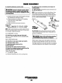
9. Unbolt elbows at head and remove the exhaust manifold
in its entirety.
10. Remove the engine alternator and raw water pump.
2. Remove engine wiring harness in its entirety. Label
terminal connections to insure proper reattachment.
11. Remove the engine mounted fuel filter and fuelline to
injection pump. (Note the arrangement of sealing washers on banjo bolts at fuel filter and injection pump.)
C
o ~~: ~~
iBIO~
\
DAMPER
PLATE
,DAMPER PLATE
,BOLTS
~·t~
00
Engines & Generators
8
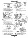
12. Remove the thennostat housing and the thennostat.
Leave temperature sending unit in place.
13. Remove the coolant circulating pump.
14. Remove the air intake silencer.
15. Remove all the high pressure injector lines from the
injection pump to the injectors. Leave the two upper line
clamps in place.
NOTE: Cap the ends of the lines and the connections at the
injection pump and at the injectors to prevent entry of
foreign material.
16. Remove the intake manifold.
17. Remove the fuel return line from the top of the injectors
and from the fuel injection pump. (Note the washer
arrangement on fuel return line banjo bolts. Cap all the
openings on the fuel return line, injectors and injection
pump.)
" ROCKER ARM,
\ ASSEMBLY ,
a. Remove the rocker arm assembly.
b. Remove the valve stem caps so as not to lose them
when removing the cylinder head. Label each cap as
top which valve it belongs.
c. Remove the push rods. Label each rod as to
which valve
it belongs.
d. Lift the cylinder head off the engine .
a. Remove the fuel injectors, dust seals and sealing
washers from the cylinder head.
b. Remove the glow plugs.
18. Remove the crankcase breather hose and rocker
arm cover.
.
""",....
\
'J
\
',. ....:J.--l ROCKER ARM
~i
.;
\ \ COVER
INTAKE MANIFOLD:
jASSEMBLyL ,.
\
\
r
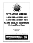
19. Remove the cylinder head.
;.
NOTE: Loosen the cylinder head bolts equally and gradually
in the' order shown in ~he dia~r~
,.'
i
! 14;1 10
I :"
.
1.6 2 3 ; 7
i
/
, ,~~ @I@..
i13
I
9
14
.J
8 /12
1
i
I
20. RelIlove the ~~. ~ter~assembl~
Engines & Generators
9
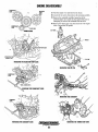
ENGINE DISASSEMBLY
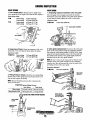
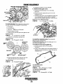
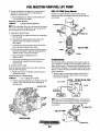
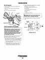
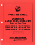
21.
Remove the injection pump. Scribe the mating marks
on the pump body flange and the timing gear case
k:l
before removing. I~ '.
. I
.
I REMOVING THE·
CRANKSHAFT
PULLEY
i
.
/
SCRIBED
{
MATING MARKS
.'
II'
!.
I ....
~
ilNJECTION
(PUMP
.
NOTE: Remove the crankshaft pulley bolt with the aid ofa
a. Remove the cover and the lock nuts.
38 mm socket and draw the pulley off the front crankshaft.
b. Loosen the two injection pump hold down nuts. Do
not remove entirely. The hold down nut on the engine
side of the pump can be loosened by using a 114" /
universal socket and extension with ratchet.
22.
23.
24.
Remove the timing gear cover.
Remove the injection pump gear and the oil baffle plate.
Remove the central idler gear and idler gear spindle.
25.
With a suitable puller remove the crankshaft gear
and key.
Remove the camshaft gear using a suitable puller.
1
I
INJECTION PUMP
GEAR AND BAFFLE PLATE
\718
c. Remove the nut and lockwasher from the injection
pump shaft.
NOTE: Take care not to drop the nut and the washer into
timing gear case.
d. Place the keyway on the injection pump shaft in
the 12:00 position with the aid of the front crankshaft
pulley bolt before attempting to remove the
injection pump.
D
•
e. With the use of extractor #49 SE 01 157 apply
sufficient pressure to loosen the pump from the keyed .
gear. The loose hold down nuts will prevent the pump
from falling from the engine..
)
•
_
~~TlMING \
e ..
/IC~~E
iGEAR ;
I
~INJECTION
,~,.~
J
718.
PUMP GEAR
\TIMING GEARS· 718
\
KEYWAY/
NOTE: If an extractor is not available, replace the nut on the
injection pump shaft loosely and with a nylon drift and
hammer gently tap the injection pump shaft to dislodge it
from the keyed drive gear. )
f. Once loosened, remove the hold down nuts and
washers and carefully withdraw the pump from the
drive gear and engine so as to avoid losing the
injection pump drive key inside the timing case.
NOTE: The 71 C gear arraignment uses two small idler gears
in place of a single idler gear. The following disassembly
illustrations show the 71 B gear arraignment.
Engines & Generators
10
ENGINE 'DISASSEMBLY
'INJECTION
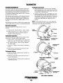
27. Thrn the engine over and remove the oil pan.
28. Loosen the set screw, then remove the oil pump assembly.
29. Remove the camshaft carefully. Insure that all the
pushrod tappets are seated into the engine block prior to
attempting to remove the camshaft from the block.
30. Remove the timing gear ~~ from the front of the engine
block. Discard the old gasket.
/
llOLER GEAR
'J TIMING ~EARS
OIL PAN:
!
~
REMOVING THE INJECTION PUMP GEAR
\.'.~
.. ~~..: ....
•• 0
. "
,Jfi!J
'~~
REMOVING THE OIL PAN.
.~ ~ ~
.
-
'..~
.. -
G
-...
.,'
REMOVING THE TIMING GEAR CASE
Engines & Generators
11
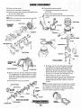
ENGINE DISASSEMBLY
31. Remove the rear oil seal.
32. Remove the connecting rod bearing caps.
33. Remove the piston and connecting rod assemblies from
the top of the cylinder block.
34. Remove the main bearing caps.
38. Disassemble the piston assembly.
a. Using the piston ring remover, remove the
piston rings.
b. Remove the wrist pin snap rings.
'c. Using a nylon drift, drive the wrist pin from the piston
and rod.
NOTE: Mark the bearing caps to insure properr~~sembly.
35. Remove the crankshaft.
CRANKSHAFT
\ ASSEMBLY .
\PISTON
I;IST~N RING:
"
~~
I,
i
I
1'-
[lARGE END
'._-
/
.'.--~\
LPISTON ASSEMBLY
REMOVING THE
VALVES
I
36. Remove each valve from the cylinder head assembly.
Use an appropriate valve spring compressor to aid: in
disassembly. Arrange or label valves so as to replace
them in the cylinder and the guide from which they
were removed.
37. Disassemble the rocker arm assembly.
(
I
I\
\
"\
.\
\
d. Protecting your eyes with safety glasses, disengage
and withdraw the snap rings. Although mechanics
generally press out (and sometimes hammer out)
pistons pins, these practices should be discouraged.
Instead, take the time to heat the pistons, either with a
heat gun or on a hot plate. Pins will almost fall out.
e. While the piston is still warm, check for bore
integrity. Insert the pin from each side. If the pin binds
at the center, the bore might be tapered; if the bore is
misaligned, the pin will click or bind as it enters the
far boss.
\ NOTE: The number stamped on the rod shank and cap should
1\ correspond
to the cylinder number. Sometimes these numbers
are scrambled or missing, and the mechanic must supply
l them. Stamp the correct numbers on the pads provided and,
l,tO prevent confusion, deface the originals.
I
Engines & Generators
12
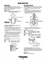
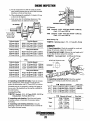
ENGINE INSPECTION
CYLINDER HEAD
1. Visual Inspection. Check the cylinder head for cracks
or any other damage and, if necessary, repair or replace it.
2. Distortion Inspection. Measure the cylinder head
surface distortion with a straight edge and the thickness
gauge. Take 6 measuring positions as shown in the diagram.
IT the distortion exceeds permissible limit, replace the
cylinder head. (The head has no allowance for planing and
must be replaced, not renewed.)
Cylinder Head Distortion Limit
71 ani C
Positions: 1, 2
3,4,5, 6
I
REMOVING THE.
INSERT
0.10 mm (0.004 in)
0.25 mm (0.010 in)
a Use a new welch washer.
h. Insert the welch washer so that its convex surface
is toward the cylinder head gasket.
c. After installation, check to see if the insert is
completely fixed in place.
FEELER GAUGE
i
~
WELCH WASHER"'-..
2·
!-~~~-&::"""~-e~~~~~~~~5
VALVE SEAT
6
NOTE: Valve seat inserts cannot be fitted to this engine.
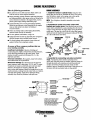
1.
1. Valve Seat Angle. Valve seat angle is 45° and 30°
respectively for intake and exhaust sides. The standard
contact width of the valve seat is 2.0 mm (0.08 in) for both
intake and exhaust sides. If the valve margin is less than the
pennissible limit, replace the valve.
3. Insert Inspection. Check for cracks or damage on the
insert and, if detected, replace it.
4. Insert Replacement. To remove the insert, place a
suitable drift into the injection nozzle hole, then tap the drift
Mllve margin limit
71 ani C
with a hammer. To install, set the insert in position and insert
the welch washer into the insert guide hole. Secure the welch
washer by tapping the raised center of the welch washer.
1.35 mm (0.053 in)
12mm(.08 in)
"I
Engines & Generators
13
3{7 mm (1.25 in)
EXHAUST
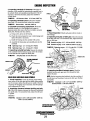
ENGINE INSPECTION
2. Dimension L. Check the protruding length of the valve
stem, if it exceeds the specification, correct it as follows:
Dimension L Standard
71 Bn1 C
48.0 mm (1.890 in)
a. When dimension L becomes large 0 - 0.5 mm (00.0202 in) from the standard, it is possible to use both
the valve and the cylinder head.
g. Check for contact between the valve and valve seat by
applying a thin coat of Prussion Blue (or Redlead) on
the valve seat contact face, then insert the valve into
the valve guide and press fit the valve on the valve
seat.
NOTE: Do not rotate the valve!
II
/
DIMENSION L
CONTACT FACE
h. Check if the valve seat contact face contacts the
center position of the valve contact face. If the contact
position is not centered, repair the valve and the
..
valve seat.
b. When dimension L becomes to large 0.5 - 1.5 mm
(0.20 - 0.059 in) from the standard, adjust the
dimension L to the standard by adding some washers
(inner diameter 12.8 mm (0.504 in ), outer diameter 39
mm (1.535 in) between the lower spring seat and the
cylinder head.
c. When dimension L becomes to large ( more than 1.5
mm, 0.059 in) from the standards, install the valve with
a new one, and recheck dimension L.
d. When dimension L becomes 1Q large 0 - 0.5 mm
(0 - 0.0202 from the standard, replace the valve.
e. When dimension L becomes to large 0.5 - 1.5 111m
(0.020 - 0.059 in) from the standard, replace the valve
and adjust the dimension L to the- standard by adding
some washers between the lower spring seat and the
cylinder head.
f. When dimension L becomes to large (more than 1.5
mm (0.059 in) from the standard, replace both the
valve and the cylinder head.
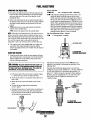
2. Stem Wear Inspection. If the valve stem is bent or its
diameter is less than the limit, replace the valve.
Stem diameter limit
71B
Intake 8.884 mm (0.350 in)
Exhaust 8.864 mm (0.349 in)
7.880 mm (0.3102 in)
71C
Intake
Exhaust 7.867 mm (0.3097 in)
I,
'LOWER
SPRING
SEAT
,
l ..
i
! WASHER
\. \
Engines & Generators
14
CHECKiNG VALVE STEM WEAR ....
ENGINE INSPECTION
VALVE SPRING
VALVE GUIDE
1. Free Length Check. Measure the free length of the
valve spring and if free length is less than the limit, replace it.
1. Inspecting clearance between valve and guide.
Set a dial gauge with a magnet and check the clearance
between the valve stem and the valve guide. If the clearance
is more than the limit, replace the valve or valve guide.
Valve Spring Limit
71 B
Inner spring
Outer spring
71C
Inner spring
Outer spring
42 mm (1.654 in)
43.6 mm (2.083 in)
43.6 mm (1. 717 in)
52.9 mm (1.717 in)
Clearance Limit
0.127 mm (0.005 in)
2. Valve guide replacement. To remove the valve guide,
press out the valve guide towards the combustion chamber
side, using the valve guide installer (49 0636 165A). Again
using the valve guide installer, press in the valve guide into
the cylinder head until the valve guide height reaches the
indicated scale on the valve guide installer.
2. Squareness Check. Check the squareness of the valve
spring and, if it is more than the limit, replace the spring.
Squareness Limit
71 Bn1 C
1.25 mm (0.049 in)
1.37 mm (0.054 in)
NOTE: Be sure to press in the valve guide so that the inside
chamber on the valve guide end faces to the combustion
chamber side. After the pressure fit, check the length of the
protruding portion of the valve guide.
Protrusion Standard
71 Bn1C
16.5mm(0.650in)
VALVE GUIDE
INSTALLER
3. Fitting Pressure Check. Check the valve spring fitting
pressure with a valve spring tester and, if the pressure is less
than the limit, replace the spring.
NOTE: Measure the fitting pressure after compressing the
spring several times.
71 Bn1 C Spring Fitting Pressure
Inner Spring
Outer Spring
Fitting Length 37.8 mm (1.49 in) 40.3 nun (1.59 in)
Fitting Pressure Limit
1013 kg (22.7Ib)
14.5 kg (32.0 lb)
~SJ
TESTING THE SPRING FIniNG PRESSURE
,>",
VALVE SPRING
TESTER
SPECIMEN VALVE
SPRING
Engines & Generators
15
HEIGHT ABOVE
THE SPRING SEAT
16.5 mm (0.65 in)
ENGINE INSPECTION
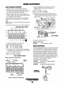
ROCKER ARM
TAPPET
1. Visual Inspection. Check each component part of
rocker arm assembly for cracks or other damage. Check if
the oil passages of the rocker arm and shaft are clogging and,
if necessary, repair or replace it.
1. Visual inspection. Check the tappet for cracks and
"AT
RETAINING RING.......
~-JAMNUT
BRACKET _ _ _
~
other damage and, if damaged replace the tappet. Check for
abnormal wear of the portion of the tappets that contact
with the cam, and if anyone is abnormally worn, replace
the tappet.
1~
2. Inspecting Clearance Between Tappet and Tappet
Bore. Check the clearance between the tappet and tappet
,
bore and, if the clearance is greater than the limit, replace the
tappet or cylinder block.
Clearance Limit
71an1C 0.10 mm (0.004 in)
SPRING
WASHER
TAPER PIN RECESS
-®~
l@i
\"
SCALLOP
2. Inspecting clearance between rocker arm and shaft.
Check the clearance between the rocker arm and shaft and, if
it exceeds the limit, replace the rocker arm bushing or shaft.
Clearance Standard
71 an1C 0.016 - 0.061 (0.0006 - 0.0024 in)
limit - 0.07mm (0.003 in)
3. Rocker Arm Bushing Replacement Using a suitable
mandrel and press, press out the bushing. Aligning the oil
passages of the rocker arm bushing, press the bushing into
the rocker arm. After the rocker arm bushing has been
replaced, ream the bushing bore with a reamer so that the
clearance between the bushing and shaft becomes equal to
the standard clearance.
TAPPET
CLEARANCE
..
CYLINDER BLOCK
1. Visual Inspection. Check the cylinder block for cracks
and damage. If necessary, repair or replace it entirely Check
to see that oil or cooling water passages ar" not clogged and,
. if clogged, remove with compressed air or a wire probe.
REMOVE LOCATING DOWELS
BEFORE INSPECTING
- , Wi
:w
~Pi
~ "$
".J
2. Distortion Inspection. Check the gasket face distortion
of the cylinder block and if it exceeds the limit, repair or
replace it.
Distortion limit:
71 ani C (1) (2) 0.10 mm (0.004 in)
0.25 mm (0.010 in)
(3) (4)
REPLACING
THE BUSHING
~:I--4
. DISTORTION INSPECTION
, REAMING THE BUSHING
BORE
Engines & Generators
16
2
ENGINE INSPECTION
CYLINDER LINER
PISTON AND PISTON RING
1. Wear Inspection. Measure the liner bore at three
positions of upper, middle and lower portions with a cylinder
gauge in X-X and Y-Y directions as shown. If wearing
exceeds the limit, replace the liner.
Cylinder Liner Bore
71 Bn1 C 88.925 - 88.950 mm (3.5010 - 3.5020 in)
Wear Limit 0.20 mm (0.008 in)
1. Visual Inspection Check the sliding surface and ring
groove of the piston for wear, scratches or any other damage.
a. Inspecting the clearance between the piston and the
cylinder liner.
b. Check the clearance between the piston and the cylinder
liner by measuring the cylinder bore and the piston
diameter and, if the clearance exceeds the limit, replace
the cylinder liner or piston.
Y
X--I+-- ---J+-X
' - '.....- / X - X IS THE THRUST DIRECTION
y
CYLINDER LINER
MEASURING GAUGE
PISTON LINER
2. Cylinder Liner Replacement. Hydraulic press or
similar device is needed.
a. Attach the cylinder liner puller and installer to the lower
rim of the cylinder liner, then press out the liner.
b. Check for scratches on the cylinder block side and, if any,
remove them by using extremely fine emery paper with
engine oil.
c. To install the liner, apply engine oil on the cylinder block
bore and the liner exterior, then set the liner on the
cylinder block. Using the cylinder liner puller and
installer, press the liner into the cylinder block.
c. To measure the piston <1lameter, measure 18 mm (0.7 in)
above from the piston bottom at right angle to the
piston pin.
Piston and Cylinder Clearance
71B
0.044 - 0.70 mm (0.0017 - 0.0028 in)
71C
0.054 - 0.080 mm (0.0021 - 0.0031 in)
Standard Piston Diameter
71 B
88.880 ± 0.013 mm (3.4989 ± 0.0005 in)
71C
88.872 - 88.898 mm (3.499 - 3.500 in)
NOTE: Press the liner in straight. When press fitting
the liner, keep the pressure within a range of 1-3 tons
_-;:::;::=::::::;;;-_..--SUB COMBUSTION
CHAMBER (71C)
(2,200 - 6,600 [b).
Measure the liner protrusion and correct it if necessary.
Protrusion Limits
71 B
0.101 - 0.000 mm (0.0040 - 0.0000 in)
71 C
0.659 - 0.790 mm (0.026 - 0.031 in)
PROTRUDING LENGTH
TAKE MEASURE UP
.18 mm (0.7 in)
3. Piston Ring Inspection Check the piston ring for
breaks, seizure and wear and, if any of these conditions exist,
replace the ring. Check the clearance between the piston ring
and the ring groove and, if it exceeds the limit, replace the
ring.
Clearance limit
71Bn1C 0.30 mm (0.012 in)
Engines & Generators
17
ENGINE INSPECTION
~SMALL
END BUSHING
PISTON PIN
OIL HOLE
PISTON PIN
LARGEEND--
: CLEARANCE 0.0005 - 0.0015 mm
(0.012 - 0.039 in)
OIL HOLE
BUSHING~,~~~=~!=~r~~~
4. Small end bushing replacement. Using a press,
press out the bushing. Align the oil passages of the
connecting rod and the small end bushing; press in the
bushing to the connecting rod bore. After a small end
bushing has been replaced, ream the bushing bore to obtain
the specified clearance between the small end bushing and
the piston pin.
~BEARINGS
~
BEARING CAP
PRESS
INSTALL NEW
BEARING CAP
BOLTS
MANDREL---------.
REMOVING THE
SMALL END
,BUSHING
CONNECTING ROD
1. Visual Inspection. Check the connecting rod for cracks
or other damage and, if necessary, replace it.
2. Bend Inspection. Using a connecting rod aligner, check
the bend and twist of the connecting rod and, if exceeding
the limit, repair it with a press or replace it.
Bend Limit
71B/71C 0.05 mm (0.002 in)
per 100 mm (3.9 in)
'/'
/
PRESSING ,IN
THE NEW
('BUSHING
OIL HOLES - - - - I I l ..1
OIL HOLES,
{7
NOTE: When reaming the bushing, correctly insert the
reamer in the bushing. In order to prevent unevenness on
the bushing surface, the reaming should always be made in
the cutting direction. Make certain the reamer is stopped at
different positions at all times.
5. Inspecting connecting rod side play. Check the
connecting rod side play with the <ljal gauge and, if it
exceeds the limit, replace the connecting rod and crankshaft.
Side Play Limit
71B/71C
0.40mm (0.016 in)
3. InspeCting clearance between the piston pin and
small end bushing. Check the clearance between the
piston pin and the small end bushing and, if it exceeds the
limit, replace the piston pin or small bushing.
Clearance
71 B Standard: 0.012 - 0.031 mm (0.0005- 0.0015 in)
Limit: 0.05mm (0.002 in)
71C Standard: 0.014 - 0.041 mm (0.0006 - 0.0016 in)
Limit: 0.05 mm (0.002 in)
CONNECTING ROD
SIDE PLAY TEST
Engines & Generators
18
ENGINE INSPECTION
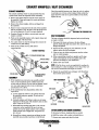
CRANKSHAFT
5. Inspecting piston ring end gap. Position the piston
ring into the bottom of the cylinder liner. Measure the piston
ring end gap and, if it exceeds the limit, replace the ring.
1. Visual Inspection. Check the crankshaft for cracks or
other damage. If cracking is suspected, thoroughly clean the
crankshaft and perform a color test on the shaft, or run a candle flame over the crankshaft and look for oil seepage from
cracks. If any cracks are detec~, repl~ce the crankshaft.
Piston Ring End Gap Limit
71Bn1C
1.5 mm (0.59J.in)
. Be sure to position the piston ring below the ring sliding
surface of the cylinder liner.
PERFORMING ACOLOR TEST
CRANKSHAFT........
Check for clogging of oil passages and, if clogged, remove
with compressed air or wire.
2. Runout inspection. Check the crankShaft runout and, if
6. Inspecting connecting rod bearing. Check the
it exceeds the limit, replace the crankshaft.
connecting rod bearing for peeling and thermal damage. If it
is severe, replace the bearing.
Runout Limit
71Bn1C
7. Inspecting connecting rod bearing clearance.
Using the plastigauge, measure the oil clearance of the
connecting rod bearing and, if it exceeds the limit, replace
the connecting rod bearing.
\
Con~ecting Rod Bearing Clearance
!
71 B
71 C
Standard:
Limit:
Standard:
Limit:
0.05 mm (0.01020 in)
CRANKSHAFT RUNOUT
..INSPECTION
0.012 - 0.031 mm (0.0005 - 0.0012 in)
0.05 mm (0.002 in)
0.036 - 0.076 mm (0.0014 - 0.0030 in)
0.10 mm (0.004 in)
GAUGE
Undersize Bearing: 0.254 mm (0.010 in)
0.508 mm (0.020 in)
0.762 mm (0.030 in)
3. Inspecting crank pin and journal. Support the crankshaft on both ends using V-blocks. Measure the diameter of
each crank pin and crankshaft main journal and, if the diameter is less than the limit, refinish the crank pin and main journal to size for the next undersize bearing.
71B
Crank pin standard diameter
57.112 - 57.125 mm
(2.2485 - 2.2491 in)
Wear limit
0.05mm
(0.002 in)
Main journal standard diameter
69.812 - 69.825 mm
(2.7485 - 2.7491 in)
Wear limit
0.05mm
(0.002 in)
71C
CONNECTING ROD BEARING CLEARANCE
Connecting Rod Cap Tightening Torque
7.8 - 8.0 m-kg (56 - 58 ft-lb)
6.9 - 7.5 m-kg (50 - 54 ft-lb)
71 B
. 71 C
Crank pin standard diameter
53.0 - 53.013 mm
(2.0866 - 2.0861 in)
Wear limit
0.05mm
(0.0020 in)
Main journal standard diameter
65.0 - 65.013 mm
(2.5591 - 2.5596 in)
Wear limit
0.05mm
(0.0020 in)
Engines & Generators
19
ENGINE INSPECTION
For the measurement on both the crank pin and the
main journal, measure them at vertical and horizontal
directions on front and rear places.
b, When refinishing the crankshaft, it's finish to Rl mm
as shown in the diagram.
c, Refer to the chart for refinishing dimensions of the
crankshaft where an undersize bearing is used.
8,
I
Oil Clearance
~1-=-3.71~.~3.~gg~m~m~e!IJ==~~~~~~
71 B Standard: 0.059 - 0.090 mm (0.0020 - 0.0040 in)
Limit: 0.12 mm (0.005 in)
71C Standard: 0.040 - 0.091 mm (0.0016 - 0.0036 in)
Limit: 0.12 mm (0.005 in)
(0.146· 0.157 In)
R2 =3.20 . 3.61 mm .
(0.126·0.142 in)
Undersize bearing
0.254 mm (0.01 in)
0.508 mm (0.02 in)
0.762 mm (0.03 in)
71B
Crank pin diameter
56.868 - 56.871 mm (2.2389 - 2.2391 in)
56.604 - 56.617 mm (2.2285 - 2.2312 in)
56.350 - 56.363 mm (2.2185 - 2.2191 in)
Undersize bearing
0.254 mm (0.01 in)
0.508 mm (0.02 in)
0.762 mm (0.03 in)
Main journal diameter
69.558 - 69.571 mm (2. 7385 - 2. 7391 in)
69.304 - 69.317mm (2.7182 -2.7291 in)
69.050- 69.063 mm (2.7185 -2.7191 in)
Main Bearing Cap
71 Bn1 C lightening torque: 11.0 -11. 7 m-kg (80 - 85 ft-lb)
CAMSHAFT
1. Visual Inspection. Check the camshaft for cracks and
damage. If necessary, replace the camshaft.
2. Inspecting cam height. Measure the cam height and, if
it is less than the limit, replace the camshaft.
71Bn1C Cam height limit: 42.478 mm (1.6724 in)
71C
INTAKE AND EXHAUST CAM
Crankpin~
Undersize bearing
0.254 mm (0.01 in)
0.508 mm (0.02 in)
0.762 mm (0.03 in)
52. 733 - 52. 746 mm (2.0761 - 2.0766 in)'
52.479 - 52.492. mm (2.0661 ~ 2.0666 in)
52.225 ~ 52.238 mm (2.0561 - 2.0566 !It))
Undersize bearing
0.254 mm(O.Ol in)
0.508 mm (0.02 in)
0.762 mm (0.03 in)
Main jour1llll diameter
64.733 - 64.746 mm (2.5485 - 2.5491 in)
64.479 - 64.492 mm (2.5385 ~ 2.5391 in)
64.225 - 64.238 min (2.5285 - 2.5291 in)'
~H"G~IW
!
3. Inspecting camshaft journal. Check the camshaft
journal and, if wearing exceeds the limit, replace the
camshaft.
71 B Diameter ofJournal
Wear Limit
No.1 51.910 - 51.940 mm (2.0437 - 2.0449 in) 0.008mm
No.2 51.660 - 51.690 mm (2.0339 - 2.0351 in) (0.0003 in)
No.3 51.410 - 51.440 mm (2.0240 - 2.0252 in)
No.4 51.160 - 51.190 mm (2.0142 - 2.0154 in)
4. Inspecting crankshaft end play. Check the end play
of the crankshaft and, if the end play exceeds the limit,
replace the thrustwasher with 0.178 mm (0.007 in) oversize.
Crankshaft end play is measured by setting a dial gauge on
the rear end of the crankshaft and moving the crankshaft in
the axial direction.
Crankshaft End Play
71Bn1C Standard: 0.14 - 0.39 mm (0.0055 - 0.0153 in)
End play limit: 0.40 mm (0.0157 in)
5. Inspecting main bearing. Check the main bearing
for peeling, seizure or fusion and, if necessary, replace
the bearing.
6. Inspecting main bearing clearance. Using the
plastigauge, measure the oil clearance and, if it exceeds the
limit, replace the main bearing.
Front
Center
Rear
1'WV"wesiERBEICE
I Engines & Generators
20
71 C Diameter ofJournal
52.06 - 52.09 mm
(2.0497 - 2.0508 in)
51.81 - 51.84 mm
(2.0398 - 2.0409 in)
51.31 - 51.34 mm
(2.0201 - 2.0212 in)
Wear Limit
0.008mm
(0.0003 in)
ENGINE INSPECTION
4. Inspecting camshaft oil clearance. Check the oil
clearance of the camshaft by measuring the camshaft bore in
the cylinder block and camshaft journal diameter. If the oil
clearance is more than the limit, replace the camshaft or
cylinder block.
71 ani C Oil clearance limit: 0.145 mm (0.0057 in)
5. Inspecting camshaft runout. Check the camshaft
runout and, if it exceeds the limit, replace the camshaft.
71 ani C Runout limit: 0.08 mm (0.003 in)
6. Camshaft front bearing replacement. Mount the
camshaft assembly in a vise equipped with copper or
aluminum plate, then remove the bolt, lock plate, cam gear,
thrust plate, bearing outer face and key.
R, Using a press, press out the bearing.
b, Check the removed parts for wear or other damage and
replace the parts as necessary.
c, Install the bearing onto the camshaft with a press.
d, Assemble the thrust plate and camshaft gear onto the
camshaft.
71 a Tightening torque: 6.4 - 9.5 m-kg (46 - 69 ft-Ib)
71 C Tightening torque: 6.2 - 7.0 m-kg (45 - 51 ft-lb)
7. Inspecting camshaft end play. Measure the end play
of the camshaft with the thickness gauge and if the end play
is more than the limit, replace the thrust plate.
71 ani C End play limit: 0.3 mm (0.012 in)
CHECKING
CLEARANCE
BETWEEN THE 1.\\\\ \\'K\\\<\I~\,(\\'I.'
BUSHING
AND SPINDLE
GEARS
1. Visual Inspection Check each gear tooth for cracks or
other damage.
2. Inspecting end play of idler gear. Check the end play
of the idler gear and, if it exceeds the' limit, replace the thrust
plate or idler gear.
71 a Standard end play: 0.15 - 0.30 mm (0.0059 - 0.0118 in) ,
71C Standard end play: O.~O'" 0.030 mm (0.0079 -0.0118 in)
71 ani C Tightening torque: 2.3 - 3.2 m-kg (16.6 - 23.1 ft-Ib)
FQE~:~:;~;~
).
IDLER GEAR ~,
')
I~
THRUST PLATE
~):
TESTING CAMSHAFT'
END PLAY
CHECKING
IDLER GEAR
END PLAY
NOTE: THE 71C USES _ ~
TWO IDLER GEARS;;;"... /
~"(.
3. Inspecting backlash between gears. Check the
, backlash between each gear and, if it exceeds the limit,
replace the gears.
NOTE: Before inspecting the backlash, check the end play of
the idler gear and clearance between the idler gear bushing
and spindle.
71an1C Standard: 0.10 - 0.17 mm (0.004 -0.007in)
Backlash limit: 0.30 mm (0.012 in)
IDLER GEAR AND IDLER GEAR SPINDLE
1. Visual inspection. Check the damage on the bushing
inner surface of the idler gear and the spindle sliding surface
and, if necessary, replace the idler gear or spindle. Check the
oil passage for clogging and, if necessary, clean the passage
with compressed air or wire.
'
2. Inspecting clearance between bushing and spindle. Check the clearance between the idler gear bushing and
the spindle and, if it exceeds the limit, replace the idler gear
or spindle.
Clearance
71 ani C Standard: 0.034 - 0.084 mm (0.0013 - 0.0033 in)
Limit: 0.15 mm (0.006 in)
' ....'walERBEICE
I Engines & Generators
21
ENGINE INSPECTION
PUSH ROD
REAR OIL SEAL
1. Visual Inspection. Check the push rod for damage on
1. Inspecting oil seal. Check the oil seal lip for wear or
other damage and, if necessary, replace it.
2. Oil seal replacement. Upon inspection, finding the
existing seal worn or frayed, pick the old seal halves out of
their grooves and thoroughly clean the half-housings.
a. With half-housing held in a soft-jawed vise and the
seal recess uppermost, settle one inch (25 mm) of the
seal wick at each end into the groove. Make certain
that each end of the seal projects 0.25/0.51 mm
(0.010/0.020 in) beyond the joining faces of the
two-piece housing.
b. Press the remainder of the seal wick into the groove
starting from the center and working outwards.
c. Using a suitable round bar, roll and press the seal into
place in both half-housings.
both ends. If it is severe, replace it.
2. Bend Inspection. Check the push rod for bend and, if
it exceeds the limit, replace it. Place the push rod on a flat
surface and measure the clearance between the center of the
push rod and the flat surface. Replace the push rod if the
wear limit is exceeded.
71 B171C Bend limit: 0.19 mm (0.0075 in)
. TESTING THE
PUSH ROD
REAR OIL SEAL
MAIN CAP BOLT
PUSH RODS
TIMING GEAR COVER
1. Inspecting timing gear cover. Check the timing gear
LOWER SEAL
HOUSING BOLT
cover and oil seal for any damage. If necessary, replace the
cover or oil seal.
2. Oil seal replacement. To remove the oil seal, use the
oil seal puller and installer and pull out the oil seal. To install,
apply the engine oil on the outer periphery of the oil seal,
then press in the oil seal with oil seal puller and installer.
o
OIL SEAL PULLER AND INSTALLER
SEAL HOUSING
CLAMP BOLT
~ OIL SEAL
',.
~
----IIV~--~--l~~III~I--
TIMING GEAR COVER
3. To refit the assembly: Thoroughly clean the butt joint
between the half-housings.
a. Lightly coat the butt joint faces with a liquid gasket
compound similar to Dow Corning Silastic 732 RTV
adhesive/sealant. Lubricate the exposed diameter of the
wick seals with graphite grease.
b. Oil the crankshaft at the oil return groove. Place the
half-housings in position against the gasket and the
engine block and locate all the bolts into the block and
bearing cap face finger tight only.
c. Tighten the clamping bolts to a temporary torque of
0.55 - 0.83 kg m (4 - 6 lb ft).
d. Tighten the bolts in the block and cap to a torque of
1.66 kgfm (121b ft).
e. Finally, tighten the clamping bolts to a torque of 1.66
kgf m (12 lb ft).
Dll
TIMING GEAR OIL SEAL
REPLACEMENT
OIL SEAL INSET
6.35·7.62 MM
(0.250 • 0.300 IN)
Engines & Generators
22
ENGINE REASSEMBLY
Take the following precautions:
ENGINE ASSEMBLY
• Be careful no.t to. mix bo.lts and nuts. Metric and S.A.E.
bo.lts are used o.n vario.us engine assemblies.
• During assembly, recheck clearances and insure that parts
are being assembled in their pro.per o.rder and facing in the
co.rrect directio.n in relatio.n to. the engine blo.ck, such as,
pisto.ns, pisto.n rings, bearings and bearing caps.
• Apply lubricating o.il to. mo.ving parts during assembly.
Insure that mo.ving parts, when assembled o.n the engine,
ro.tate o.r slide and are no.t subject to. binding o.r
excessive tensio.n.
• If there are mating marks scribed during disassembly,
reference them co.rrectly fo.r assembly.
• Use new gaskets, lockwashers, o.-rings, etc.
• Tighten the bo.lts and nuts o.n impo.rtant parts o.f engine to.
specified to.rques using a reliable to.rque wrench.
• Use liquid sealants when required o.n nuts, bo.lts and
gaskets. Refrain fro.m using tape sealants.
1. Install the valves in cylinder head. Using the valve
spring lifter arm and pivo.t, assemble the valve, lo.wer spring
seat, o.il deflecto.r, inner valve spring, o.uter valve spring,
upper spring seat and taper sleeve in this o.rder.
Be aware of these common problems that can
occur during assembly.
Insufficient Lubrication. Heavily o.il sliding and
reciprocating parts, lightly o.il head bo.lts and o.ther fasteners,
except tho.se that penetrate into. the water jacket. These
fasteners sho.uld be sealed with Permatex No.. 2 o.r the
high-tack equivalent.
Reversed orientation. Mo.st gaskets, many bo.lt washers,
and all thermo.stats are asymmetrical.
Mechanical damage. Run fasteners do.wn in appro.ved
to.rque sequences and in three steps-ll2, 2/3, and III to.rque.
Exceptio.ns are to.rque-to.-yield bo.lts and ro.cker arm shaft
fasteners. The fo.rmer are to.rqued as indicated. The
latter-rocker shaft fasteners-sho.uld be bro.ught do.wn in very
small increments, wo.rking fro.m the center bo.lts o.ut. Gaskets,
especially head gaskets, might alSo. be damaged during·
assembly, they sho.uld be po.sitio.ned with great care.
NOTE: The oil deflector should be installed on the intake
valve only.
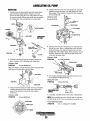
2. Assemble the rocker arm shaft, rocker shaft
brackets and rocker arms. No.te that the fro.nt end o.f the
rocker shaft is identified by a pin protruding fro.m the to.p and
a larger o.il ho.le between the supply ho.les serving #1 and #2
rocker arms. This pin fits a slo.t in the #1 ro.cker shaft suppo.rt
which prevents the shaft fro.m turning and cutting o.ff the lube
o.il to. the rocker arms and valves.
dJJ
~ .EV
ROCKER ARM
ASSEMBLY
~
TJ. ••
\
.J
I'
112 ROCKER
~.-ll-:;;",,,.:i1
/.
TA.PERPINHQLE
.'
'. 'ROCKER SHAFT/ . ()'
SUPPORT
,\
SCALLOP
3. Assemble the connecting rod, piston and piston
rings. Arrange the pisto.n and the co.nnecting rod as
sho.wn and, using the pisto.n pin installer, insert the pisto.n pin
thro.ugh the pisto.n and co.nnecting rod until the pisto.n pin
circlips can be fitted. Fit the pisto.n pin circ1ips to. their
respective gro.o.ves. Install the pisto.n rings to. ring groo.ves o.n
the pisto.n with the inscriptio.n mark o.n ring upward.
______ PISTON RINGS/
_1ST
_2ND
FRONT ___........-
FRONT OF PISTON
IS INDICATED BY
. A BOSS ON THE
BOTTOM NEAR THE
OIL HOLE
mRD'OILRING
MARK
: CHECK THE PISTON RING
GAPS WITH CARE. NEW
RINGS ARE PACKAGED
WITH DETAILED INSTRUCTIONS
. THAT OFTEN SUPERSEDE
THE SERVICE MANUAL.
Engines & Generators
23
ENGINE REASSEMBLY
4. Install the crankshaft.
NOTE: Do not apply oil to the backsides of the main
bearing shells.
PLACE A HEAVY HAMMER AND
GENTLY PRESS DOWN WITH
THE FORCE OF YOUR HAND.
THE ENTIRE SURFACE SHOULD
BE COATED WITH FRESH LUBE OIL
a. Fit the main bearings on the cylinder block and the
bearing caps respectively. Check that the oil ways align
perfectly with those in the block.
h. Fit the thrustwashers to the cylinder block so that the
oil grooves on thrustwashers face to crankshaft side.
c. Position the crankshaft to the cylinder block, being
careful not to drop the thrustwashers as the crankshaft
settles into place.
r \ r
FITTING THE
BEARING CAPS
INSTALLING PISTON AND CONNECTING ROD ASSEMBLY
'\
d. Fit the thrustwasher to the main bearing cap so that the
oil grooves on thrustwasher face to crankshaft side.
Then install the main bearing cap to the cylinder block
with arrow mark of the main bearing cap facing the
crankshaft pulley side.
Main Bearing Cap Tightening Torque
71 Bn1 C
11.0 - 11. 7 m-kg (80 - 85 ft-lb)
7. Install the idler gear spindle. Align the oil passages of
the idler gear spindle and cylinder block.
8. Install the timing gear case. Attach the straight edge
on the cylinder block, then match the surfaces of the timing
gear case end and that of the cylinder block. If the gasket protrudes from the mating surface, cut away the excess with a
knife.
.
FITTING THE
THRUST
WASHERS
5. Install the rear oil seal. Apply engine oil to the
oil seal lip .
6. Install the piston and connecting rod assembly.
a. Place the piston rings so that the ring ends are
properly spaced around the circumference of the piston
as shown on the previous page.
h. Using a ring compressor, fit the piston into the cylinder
in the position as is shown.
c. Install the caps to the connecting rods, ensuring that
the identification numbers on the cap and connecting
rod are matched.
Cap Tightening Torque (install new connecting rod bolts)
71 B
8.2 - 9.0 m-kg (59 - 65 ft-lb)
71C
6.9 - 7.5 m-kg (50 - 54 ft-lb)
INSTALLING THE TAPPETS
9. Installation of the crankshaft.
a. Insert the tappet into the cylinder block.
h. Insert the camshaft into the cylinder block.
c. Install the camshaft thrust plate.
Thrust Plate Tightening Torque
71 Bn1C
1.6 - 2.4 m-kg (11.6 -17.4 ft-lb)
Engines & Generators
24
ENGINE REASSEMBLY
h. Install the oil deflector on the crankshaft.
11. Install the timing gear cover.
a. Install the bearing housing cover on the timing
gear cover.
b. Install the injection pump drive gear cover on the
timing gear cover.
c. Install the timing gear cover and tighten the timing gear
cover attaching nuts and bolts after the crankshaft
pulley has been installed temporarily to center the seal.
Timing Gear Cover Tightening Torque
71 an1C
1.6 - 2.4 m-kg (11.6 -17.4 ft-lb)
10. Install each gear. While aligning the timing mark of
each gear, install the following gears on each position.
a. Timing gear
b. Camshaft gear
c. Idler gear (71C uses two idler gears)
d. Injection pump drive gear
. e. Install the idler gear thrust plate, then tighten the nuts.
Tightening Torque
71an1C
2.3 - 3.2 m-kg (16.6 -23.1ft-lb)
f. Tighten the camshaft gear attaching bolts.
Tightening Torque
71 ani C
6.4 - 9.5 m-kg (45 - 51 ft-lb)
12. Install the crankshaft pulley. Then temporarily
tighten the pulley attaching bolt.
13. Mount the oil pump. Apply the sealing agent on set
screw thread and tighten screw.
INJECTION PUMP
DRIVE GEAR
718
14. Position the new oil pan gasket set.
a. Position the gasket ends (A) on the gaskets
(B) and (C).
b. Apply a silicon sealing agent on the mating surfaces of
the gasket and that between the cylinder block and the
timing gear case.
~
i
•• IDLER
GEAR
NOTE: THE 71C USES
TWO IDLER GEARS
g. Mount the injection pump on the gear case, then
tighten the pump drive gear attaching nuts.
15. Install the oil pan.
Tightening Torque
71 ani C 1. 60 - 2.30 m-kg (12 - 17 ft-lb)
16. Attach the backing plate.
Tightening Torque
71 ani C 3.3 - 4.8 m-kg (23.9 - 34.7 ft-lb)
Engines & Generators
25
ENGINE REASSEMBLY
17. Install the flywheel. Install the flywheel onto the rear
end of the crankshaft.
18. Install the tabwasher plate and the flywheel
bolts. Torque the bolts. Bend the tabwasher to lock the
bolts in place.
Tightening Torque
,71Bn1C
15.5-16.3 mkg
(112 - 118ft-lh)
25. Tighten the cylinder head bolts. Tighten the
cylinder head bolts evenly in the sequence shown.
Tightening Torque
71 B
11.8 - 12.5 m-kg (85 - 90 ft-lh)
71 C
11.0 -11.7 m-kg (80 - 85 ft-lh)
14 10
20
6 2
3 7
11,
rl -
19
TABWASHER
-_-+-_
15
18
16
Q
FLYWHEEL BOLT
PATTERN
17
13
19. Tighten the front crankshaft pulley bolt.
Tightening Torque
71 Bn1 C
35 - 40 m-kg (253 - 289 ft-lh)
20. Install the two tubular dowels adjacent to cylinders
i and 4 if they were removed earlier during disassembly.
Position the gasket on cylinder block. Do not use any liquid
seal or cement.
9
4
5
12 FRONT'
WHEN NO 4 CYLINDER IS AT TOP DEAD CENTER
4
4
3
I
2
I
4 EXHAUST
4 INTAKE
2 EXHAUST
3 INTAKE
2 INTAKE
1 INTAKE
I
11 EXH~UST I
3
2
3 EXHAUST
1
1
WHEN NO 1 CYLINDER IS AT TOP DEAD CENTER
21. Position the cylinder head.
22. Insert the pushrod. Check if the push rod is securely
set in the tappet concavity.
~
26. Adjust valve clearance. Adjust the valve clearance.
Set No, 1 cylinder to IDC (top dead clearance) of the
compression stroke and adjust the valve clearance on No. 1
and No.2 intake cylinders ... and No.1 and No.3 exhaust
cylinders.
a. Tum the crankshaft once, setting the No.4 cylinder
piston at IDC (compression) and adjust the No.3
and No.4 intake cylinders ... and the No.2 and No.4
exhaust cylinders.
h. Adjust each valve's clearance by inserting a 0.012 in
(0.03 mm) feeler gauge between the rocker arm and
the valve stem.
J1llve Clearance
71Bn1C
0.30 mm (.12 in) cold
27. Install the cylinder head cover.
Torque
71Bn1C
0.3 - 0.4 m-kg (2 - 3 ft-lh)
INCORRECT
CORRECT-~1iN1
TAPPET
TAPPET
CAM LOBE
CAM LOBE
23. Position the valve cap on the top of the
valve stem.
24. Install the rocker arm assembly onto the
cylinder head. Remember that the end of the rocker shaft
having the pin occupying the slot in #1 rocker support points
toward the front (pulley) end of the engine.
NOTE: After the engine has been reassembled,
readjust the valve clearances with a warm engine, see
ENGINE ADJUS'IMENTS.
Engines & Generators
26
ENGINE REASSEMBLY
28. Install the thermostat and thermostat housing.
a. Inspect the thermostat housing and the housing gasket.
Apply some sealant to the gasket when reassembling.
b. Install the temperature switch and sendor and reconnect their wires.
c. Install a new thermostat and gasket (the old thermostat
can become a spare). When installing the new thermostat and gasket, apply a thin coat of sealant to both
sides of the gasket.
d. The thermostat can be checked for proper operation by
placing it in a pan of cold water and then raising the
temperature of the water to a boil. The thermostat
should open noticeably (with travel on the order of
1/4 in - 112 in) and be fully opened when the water
is boiling.
MANIFOLD ASSEMBLY
718
THERMOSTAT
HOUSING'
35. Install the fuel injection nozzles. Install the fuel
overflow pipe. Use new sealing washers throughout, in the
same order as were the old washers.
Injection Nozzle Hold Down Nuts Torque
71 B
1.6 - 2.4 m-kg (11.6 -17.4 ft-lb)
Injector Tightening Torque
71C 6.0 - 7.0 m-kg (43 - 51 ft-lb)
AIR BLEED PETCOCK
71C
THERMOSTAT
~
WATER TEMP...........
SENDER
"-
See FUEL INJECTORS
"
\...:;;~:::--'-"~
36. Install the glow plugs and connectors. Use
anti-seize compound on the threads.
Glow Plug Tightening Torque
71B/71C
1.0 -1.5 m-kg (7.2 -IO.8ft-lb)
29. Install the coolant pump assembly.
Tightening Torque
71B/71C
1.6-2.3 m-kg (12 -17ft-lb)
To test the glow plugs, see GLOW PLUGS
37. Mount the rocker arm cover and crankcase
vent hose.
Rocker Arm Cover Tightening Torque
71 B/71 C
0.25 - 0.40 m-kg (1.8 - 2.9 ft-lb)
38. Connect the fuel line to the engine mounted
fuel filter and the line to the injection pump. Use new
sealing washers.
39. Connect the high pressure injector lines from
the injection pump to injectors. Reinstall the
line clamp.
TorqueAttaching Nuts
71B/71C 2.5 - 3.0 m-kg (18 - 22ft-lb)
40. Install the bellhousing.
41. Install the air intake silencer.
42. Mount the engine heat exchanger and engine oil
cooler on the flywheel bellhousing.
A complete breakdown of the COOlANT
PUMP ASSEMBLY is covered on another page
in this manual.
30. Adjust the injection timing.
See INJECTION TIMING.
31. Mount the oil filter bracket and install a new filter.
When installing the new filter apply a thin coat of clean
engine oil to the rubber gasket. Tighten by hand.
32. Mount the front engine mounting bracket.
Tightening Torque
71 B/71 C
4.6 - 6.8 m-kg (33 - 49 ft-lb)
33. Install the intake manifold.
Tightening Torque
71B/71C
1.6-2.4 m-kg (11.6 -I7.4ft-lb)
34. Mount the fuel filter assembly.
The heat exchanger should be serviced at engine overhaul.
Refer to HEAT EXCHANGER.
'''''WEBJERBEICE
I Engines & Generators
27
ENGINE REASSEMBLY
43. Install the alternator and drive belt.
A CAUTION: Connect the aiternator PfDptlr/y. Should
the polarity be revelSlld, a powerful current would flow
from thB battery into the alternator, damaging the diodes
and wiring harness.
a. Install the alternator support bolt through the alternator
leg (underside) into the engine casting.
50. Install new hose connections and clamps for
COOling system.
51. Marine Engine. Reinstall the marine transmission and
fill with ATF Dextron ill.
NOTE: Some transmissions, such as the Borg Warner Velvet
Drive require oil coolers. Oil coolers should be cleaned,
pressure tested and repainted at engine overhaul. The transmission oil cooler hoses should also oe inspected. Refer to
the text on HEAT EXCHANGERS.
~
"'1111
b. Swing the alternator into position on the adjusting
bracket and fasten. Lightly tighten.
c. Adjust belt tension.
d. Tighten both bolts and recheck belt tension.
Torque Values
71 ani C
Support bolt 20 - 24 Nm (15 - 18 ft-Ibs)
Adjusting bracket bolt 12 -14 Nm (9 -10 ft-Ibs)
NOTE: Make certain the belts are perfectly aligned with the
alternator and engine pulleys. If not, insert or remove spacers as needed, to align the alternator.
~,..
~
TYPICAL
TRANSMISSION
OIL COOLERS
50. Generator. Mount the generator back end assembly
with it's control panel. Reconnect all DC wiring and reconnect all AC connections.
See ALTERNATOR for testing.
44. Install the raw water pump and drive belt.
A CAUTION: Check all AC and DC wiring connections
Insure it is in proper alignment with the crankshaft pulley.
Check tension.
to WESTERBEKES wiring schematics and diagrams.
Refer to RAW WATER PUMP
Fill the engine cooling system with antifreeze mixture and
the engine oil sump with lube oil (A.P.1. spec. CF or CG-4).
45. Install the oil and water sender and switch.
46. Install the starter motor.
47. Install the breaker panel and the
preheat solenoid.
48. Reinstall the engine electrical harness.
49. Mount the complete exhaust manifold and the
expansion tank to the cylinder head.
Torque Mounting Bolts
2.7- 3.3 m-kg (20 - 24 ft-lb)
The engine should be test run under load prior to reinstalling.
At this time readjust the valve clearances on the hot engine.
See EXHAUST MANIFOW for service and inspection.
' ....IWESJERBEICE
i Engines & Generators
28
EXHAUST MANIFOLD I HEAT EXCHANGER
EXHAUST MANIFOLD
Check the manifold pressure cap. Open the valve by pulling
it and make sure it closes when released. Make certain the
upper and lower seals are in good condition. If any doubt,
replace the cap.
The exhaust manifold, which was disassembled from the
cylinder head, should be inspected before reassembly.
1. Remove the exhaust elbows from the lower surface of
the manifold. Clean and inspect for cracks and defects.
Replace as needed.
2. Remove the exhaust nipples, elbows and plugs from
the manifold.
3. Remove water connectors from the ends of the manifold
and the end plates (71B). Be sure to note the proper location and arrangement of each for proper alignment.
4. Examine all parts for defects, corrosion and wear and
replace as needed.
HEAT EXCHANGER
5. Flush out the manifolds interior with a liquid cleaner and
rinse thoroughly with fresh water.
6. Use a pipe cleaner to clear the passage that connects the
coolant recovery tank tubing.
7. Flush out the coolant recovery tank and it's
connecting tube.
The heat exchanger should be inspected and serviced during
an engine overhaul.
EXHAUST MANIFOLD
....".,"'............... TO COOLANT RECOVERY TANK
REPLACE GASKET
1. Disconnect the hoses and remove the hose fittings,
petcock, drain plugs and zinc anode. Also, remove the end
fittings and gaskets.
2. Inspect the tube (casing) for wear and dents, if at all
suspect replace the heat exchanger.
3. Clean out any zinc debris and pressure test the coolant
and raw water passages .
4. When reassembling, install new gaskets and O-rings.
Apply some lubricant to the new gaskets and to the
petcocks and fittings as you install them.
5. Install a new zinc anode.
NOTE: All o/the above can be accomplished by sending the
heat exchanger to a heat exchanger service shop. They will
also service transmission and engine oil coolers.
6. Repaint the assembled heat exchanger with Westerbeke
heat resistant spray enamel.
CLEAN AND REPAINT
THE MANIFOLD
ASSEMBLY
HEAT EXCHANGER
1. If the manifold was ·removed as an assembly and left
intact, it can be replaced on the cylinder head in the
reverse order of removal. Do not reuse the gaskets; install
new ones and torque the bolts or nuts to the proper
specification (1O-12lb-ft).
718
2. If the manifold has been disassembled, follow the
steps below.
a. Loosely attach the elbows to the cylinder head and
the manifold using new gaskets. Do not use any
gasket sealant.
h. Gradually tighten each fitting to make sure of proper
alignment of all the parts. This should be done in three
steps. Torque to 10-12 lb-ft.
c. Reassemble the manifold end plates (71B), and the
connectors on the manifold. Be sure to use new
gaskets and coat the gasket surfaces with a suitable
gasket cement such as High Tack. Torque the nuts
to 8-10 lb-ft.
REPLACE HOSE
AFTER COMPLETED ENGlN£lSSEMBLY
5. Reconnect all hoses, replacing them as needed.
6. Refill the system with coolant as detailed above.
d. Reinstall the exhaust connections and plugs into the
manifold using Locktite-Anti-Seize on the threads.
7. Pressure test system and check for leaks.
Engines & Generators
29
FUEL INJECTION PUMP
SPEED ADJUSTMENT (PROPULSION ENGINE)
The fuel injection pump is the most important component of
the diesel engine and, therefore, calls for the utmost caution
in handling.
Speed (hertz) and timing are the only adjustments the service
dealer can perform on the injection pump. Other types of
adjustments or repairs must be performed by a qualified
injection service shop.
Early Models without Electronic Governing
3. Inspecting and adjusting the injection pump timing.
a. Remove the air intake/silencer assembly.
h. Remove the 4 high pressure injector lines that connect
between the injection pump and injectors.
c. Remove the bolt and gasket installed on the distributor
head of the injection pump.
d. Remove the valve rocker cover.
e. Rotate the crankshaft in normal direction of rotation
(use front crankshaft pulley nut) and place No.1 piston
at IDC of its compression stroke.
When servicing the injection pump, the service shop must be
advised if the pump is to be used in a generator application.
The service shop will have to remove and replace the
governor spring with a propulsion spring. Once the injector
pump is set up to propulsion specifications, the generator
governor spring is reinstalled in the injection pump and the
pump remounted on the engine. Then set the throttle for
proper engine no-load speed (hertz).
For the disassembling, inspecting, reassembling and internal
adjusting of the injection pump, it is recommended that
the pump be taken to a qualified injection service shop
authorized to service Diesel KiKi injection equipment.
The only adjustment the servicing mechanic should make to
the injection pump is the adjustment for engine idle speed.
1. Checking Idle Speed.
a. Warm up the engine.
h. Remove any specks on the crankshaft pulley with a
clean cloth and place a piece of suitable reflecting
tape on the pulley to facilitate use of a photo-electric
type tachometer.
c. Start and idle the engine.
d. Aim the light of the tachometer onto the reflecting tape
to confirm the engine speed.
e. Adjust the idle speed if the engine speed is not within
the specified value.
Normal Idle Speed
71 B
600 - 700 RPM
71 C
580 - 630 RPM
2. To adjust the engine idle speed, loosen the lock nut of
the idle adjustment bolt and tum the bolt clockwise to
increase idle speed and counterclockwise to reduce.
NOTE: To verify, the rocker arms of No.4 cylinder should be
rocking (one opening, the other closing).
f. Remove the snap ring circlip from the end of the
rocker shaft at cylinder No.1 along with the retaining
washer.
g. Loosen the rocker arm adjusting bolt so as to allow the
arm to be removed from the push rod and slide it off
the rocker shaft.
h. Press down on the valve and spring assembly and note
that the valve is hitting the top of No.1 piston. Then
remove the cap, keepers and valve springs from the
No.1 valve.
NOTE: Insure the valve moves freely in its guide. Take care
not to drop keepers down push rod hole.
i. Position a dial indicator gauge on the valve stem and
with the front crankshaft pulley nut, rock the crankshaft
counter-clockwise and clockwise to locate exact TDC
of the compression stroke for No.1 piston and then zero
the dial indicator gauge to the valve stem. (The gauge
should be able to measure up to .300 inch of valve
movement.)
;...~~_ _~~==~l=5.21
(0.205mm
in)BTDC
t
NOTE: Should engine RPM be in question, verify tachometer
readings as shown at the instrument panel with a mechanical
or strobe type tachometer at the engine crankshaft.
j. Tum the crankshaft until the indicator shows the valve
drip to be at .264 inch. This is 30 degrees BIDC.
k. Install the measuring device (Diesel Kit #57828 3520) in the bolt hole of the injection pump distributor
head. (Refer to step c.) Insure that the feeler needle of
the measuring device is in contact with the plunger
inside of the pump. Zero the measuring device scale.
ADJUSTING IDLE SPEED
Engines & Generators
30
FUEL INJECTION PUMP/FUEL LIFT PUMP
FUEL LIFT PUMP (Early Models)
4. Turn the crankshaft in the direction of normal rotation
until the No.1 piston is at IDe by referencing the
indicator on the valve stem.
The Fuel Lift pump should be cleaned and repainted.
Install a new filter as illustrated and clean the ground wire
end terminal.
a. The measuring device indicator needle should move
1.00 mm from the zero setting.
Beginning of Static Injection
71 an1C
Cam lift 1.00 mm (0.0394 in)
NOTE: If the measuring device show movement at the plunger
to be more or less than specified above, the injection pump
must be adjusted to correct the movement.
S. Adjusting the injection pump.
a. Disconnect the fuel supply and return line connections
from the pump.
h. Disconnect the support bracket at the back of the
injection pump as it attaches to the lube oil
filter adapter.
c. Loosen the two injection pump hold down nuts that
secure the injection pump to the engine.
d. Rotate the injection pump either towards the engine or
away from the engine to adjust the measuring device
indicator to show 1.0 mm of movement.
e. Secure the pump by tightening the two
hold down nuts.
FUEL LIFT PUMP
MAGNET ____I~'-+~"\
GROUND
Troubleshooting
f. Remove the measuring device and replace the bolt
and gasket and reattach all fuel lines using new
sealing washer.
6. Installing injection pump.
This lift pump operates during the start sequence when preheat is depressed. Simulate a start and depress preheat, the
pump should produce a clicking sound indicating the piston
in the pump is operating. If no clicking is heard, check that
there is 12 volts at the pump connection and that the pump is
properly grounded.
1. Test the pump by connecting a battery and fuel line as
illustrated. Fuel delivery must be 225 cc (0.5 pints) or
more every 15 seconds.
Install the injection pump in the reverse order of removal,
noting the following points:
a. Tighten the lock nut of injection pump drive gear to
the specified torque.
Tightening Torque - Injection Pump
71 ani C
4.0 - 7.4 m-kg (29 - 51 ft-lb)
h. After the injection pump has been installed, loosen the
overflow valve, and bleed the air by operating the
priming pump.
TESTING THE FUEL PUMP
FUEL LIFT PUMP
CYLINDER
r
SUCTION HEAD
APPRDX. 500 mm
NOTE: Later model WESTERBEKE engines and generators
use a solid state fuel lift pump that requires no maintenance.
This lift pump can also be adapted to replace the pump
shown above.
FUEL LIFT PUMP
INJECTION PUMP
Engines & Generators
31
FUEL INJECTORS
REMOVING THE INJECTORS.
Start to Injection
1. Disconnect the high pressure lines from the injectors and
loosen the lines at their attachment to the injection pump
and move them out of the way of the injectors. Avoid
bending the lines.
2. Remove the fuel return line in its entirety from the top of
the injectors. Take care not to lose the two sealing washers
and banjo bolt that attaches the fuel return line to each
injector.
71 B/71 C
135 - 140 kg/cm2 (1920 - 1990 lblin2J
71 B If the injection starting pressure of the nozzle is not
within the limit, loosen the cap nut on the nozzle
holder, insert flat screwdriver through the bolt hole of
the cap nut, then turn the pressure adjusting screw to
set the injection starting pressure to 200 kglcm2 (2.844
Ib/in2). Then, gradually decrease the pressure until the
injection starting pressure is 135 kglcm2 (1920 Ib/in2).
After the injection starting pressure has been adjusted,
hold the pressure adjusting screw with flat screwdriver,
then tighten the cap nut. Then check the injection
starting pressure again if it does not change.
Cap Nut Tightening Torque - Injector
71 B
4- 5 m-kg (8.82 -11.021b)
3. 71 B Remove the two nuts and washers that hold the
injector on the cylinder head.
71 C Unscrew the injector from the cylinder head.
NOTE: Clean the area around the base of the injector prior to
lifting it out of the cylinder head to help prevent any rust or
debris from falling down into the injector hole. If the injector
will not lift out easily and is held in by carbon build up or the
like, work the injector side to side with the aid of an
adjustable or open end wrench to free it and then lift it out.
SCREW
4. The injector seats in the cylinder head on a copper sealing washer. This washer should be removed with the
injector and replaced with a new washer when the injector
is reinstalled.
71 B INJECTION
PRESSURE ADJUSTMENT
INJECTION TESTING
1. Using the nozzle tester, check the spray pattern and injection starting pressure of nozzle and, if it exceeds the limit,
adjust or replace the nozzle. When using nozzle tester,
take the following precautions:
The injection starting pressure for the 71 C injectors is
adjusted by increasing or decreasing the thickness of the
adjusting shim.
The shim has 20 different thickness for every 0.05 mm
(0.0020 in), from 1.0 mm (0.0393 in) to 1.95 mm (0.0768 in).
As 0.05 mm (0.0020 in) is increased, approximately 5.0
kglcm2 (71.1 Ib/in2) of injection pressure. When replacing
the shim, grip the retaining nut in a vise and remove the
body with a wrench. Tighten the retaining nut to the
specified torque.
A
CAUTION: The spray injected from the nozzle is of
such velocity that it may penetrate deeply Into the skin
of fingers and hands, destroying tissue. If it enters the
bloodstream, it may cause blood poisoning•.
a. If the diesel fuel of the nozzle tester is stained, replace
h.
c.
d.
e.
it. At the same time, clean or replace the filter.
Set the nozzle tester in a clean place where there is no
dust or dirt.
Mount the nozzle and nozzle holder on the nozzle
tester.
Use the fuel at the approximate tempurature
of 20" C (680 F)
Operate the hand lever of nozzle tester several times to
bleed the air in the nozzle line, then move the hand
lever at intervals of one stroke per second while reading the injection starting pressure.
!
SHIM THICKNESS
ADJUSTING
SHIM
~
j
O.1mm
O.2mm
O.3mm
O.5mm
71 C INJECTION
PRESSURE ADJUSTMENT
INJECTION NOZZLE
Engines & Generators
32
FUEL INJECTORS
INSPECTING SPRAY PATTERN
ASSEMBLING
1. Operate the hand lever of the nozzle tester at intervals of
one stroke per second to check if the fuel is injected correctly in its axial direction. A nozzle is defective if it
injects fuel in an oblique direction or in several separate
strips. Also, a spray in the fonn of particles indicates a
defect. These defects may sometimes be caused by clogging with dust and, therefore, all parts should be carefully
cleaned before reassembly. (Care should be taken not to
expose ones skin to this spray as it may penetrate the skin
and cause infection.)
.
Assemble in the reverse order of disassembly, noting the following points:
1. To assemble the nozzle and nozzle holder, first assemble
the pressure adjusting nut side, and temporarily tighten the
nut. Mount the nozzle and set the needle valve to proper
position, then mount the nozzle nut.
2. After the nozzle and nozzle holder have been assembled,
check the injection starting pressure and spray condition.
Nozzle Nut Tightening Torque
71Bn1C
8 -10 m-kg (58 -72ft-lb)
Cap Nut Tightening Torque
71 B
4 - 5 m-kg (29 - 36 ft-lb)
@ ___
,~,
:;---;::
\~
NORMAL
!II:I I~I
'1':"\
FAULTY ANGLE
FAULTY DIRECTION
-WASHER
2. Apply the pressure of 115 kglcm2 (16351b/in2) to nozzle
by operating the hand lever, and check the drips from the
nozzle tip. If it drips or has a large accumulation of fuel
on the bottom, it is considered defective and should be
replaced. A very small amount of fuel may sometimes
remain on the tip of the nozzle; however, this does not
mm-lrr ~
W
CORRECT
"",0-'"
•
GASKETS .....
~
NUT-~
CD
BODY
SCREW~
M
AFTER DRIP TEST
BANJO BOLT-i
INJECTOR RETURN
LINE
~
\\,'
NUT
NOZZLE SPRING
UPPER SEAT
~
BRUSH ROD
WRONG
NOZZLE BODY
DISASSEMBLING AND INSPECTING
1. Clamp the nozzle holder in a vise, then remove the
cap nut.
2. Remove the pressure adjusting screw, then pull out the
upper seat, spring and the push rod.
3. Clamp the nozzle holder in a vise, remove the nozzle nut
then pull the nozzle out.
4. Clean the disassembled parts with clean diesel fuel, then
remove the carbon adhering on the nozzle.
"""'''-'''-~
---t.IOZZLE
NUT
CONNECTOR
BODY NUT
~~ 71C INJECTOR
71 B INJECTOR
NOTE: Do not use a metal tool to remove the carbon.
INSTALLING
S. After cleaning, check to see if the needle valve comes
down into the valve seat by its own weight when setting
the nozzle body upright position and inserting needle
valve.
6. Check that there is no flaw or other damage on mating
surfaces and sliding surfaces of nozzle body and needle
valve and, if present, replace the nozzle assembly.
Install the nozzle and nozzle holder assembly in the reverse
order of removal, noting the following points:
1. When installing the nozzle and nozzle holder assembly,
use a new copper washer.
2. 71 B TIghten the nozzle and nozzle holder assembly to
the specified torque. Switch back and forth between the
nuts; do not tighten one completely with the other loose.
Tightening Torque
71 B 1.6 - 2.4 m-kg (11.6 -17.4 ft-lb)
Tightening Torque
71C
(27mm) 6.0-7.0m-kg(43-51ft-lb)
NOZZLE BODY
TORQUE
WRENCH
Engines & Generators
33
GLOW PLUGS
DESCRIPTION
Re-install the plugs in the engine and test them again. The
plugs should get very hot (at the terminal end) within 20 to
25 seconds. If the plugs don't heat up quickly, check for a
short circuit. When reinstalling the glow plugs, use anti-seize
compound on the threads.
The glow plugs are wired through the preheat soleniod.
When PREHEAT is pressed at the control panel this solenoid
should "click" on and the glow plug should begin to get hot.
INSPECTION
A WARNING: Do no' kllllfJ a glow plug on for mom
To inspect the plug, remove the electrical terminal connections, then unscrew or unclamp each plug from the cylinder
head. Thoroughly clean each plug's tip and threads with a
soft brush and cleaning solution to remove all the carbon and
oil deposits. While cleaning, examine the tip for wear and
burn erosion; if it has eroded too much, replace the plug.
than 30 stlt:Dnds
TERMINAL END
TESTING
An accurate way to test glow plugs is with an ohmmeter.
Touch one prod to the glow plug's wire connection, and
the other to the body of the glow plug, as shown. A good
glow plug will have a 1.0- to 1.5-ohm resistance. This
method can be used with the plug in or out of the engine.
You can also use an ammeter to test the power drain
(8 to 9 amps per plug).
Tightening torque:
(J.O - 1.5 m-kg (7· iljt-lb)
TIP
A WARNING: TIuIss glow plugs will becomll VII" ho'
'0 ,he 'ouch. BII t:IIlflful no' '0 bum ,our t1ngllfS whlln
GLOWPWG
'lISting 'hII plugs
THE OHMMETER TEST·
Engines & Generators
34
ENGINE ADJUSTMENTS
VALVE CLEARANCE ADJUSTMENT
1. Warm the engine to normal operating temperature.
2. Pull off the air breather pipe from the rocker cover, and
take off the rocker cover bolts and the rocker cover to
expose the rocker shaft and valve assembly.
3. Remove the glow plugs from each of the cylinders to
enable the engine to be easily rotated by hand to position
each cylinder for valve adjustment.
Valves are adjusted with the piston in the cylinder being
adjusted at TDC (top dead clearance) of its compression
stroke.
7. Tum the crankshaft once, setting the piston of No.4
cylinder at TDC (compression) and adjust to the
following values:
Intake - No.3 and No.4 cylinders
Exhaust - No.2 and No.4 cylinders
8. Adjust each valve's clearance by inserting a 0.012 in
(0.03 mm) feeler gauge between the rocker arm and the
valve stem. Make sure to adjust all valves when the
engine is cold.
NOTE: Retorque the cylinder head bolts before adjusting the
engine s valves.
4. Loosen the head bolts in the reverse order of tightening.
CYLINDER HEAD BOLT PATTERN
19
15
. VALVE CLEARANCE
16
17
13
•
5
4'
12
FRONT'
9. Install the cylinder head cover.
, Head Cover Bolt Torq~e ..
5. Tighten the head bolts in the order shown.
Cylinder Head Bolt Tightening Torque
71 B
11.8 - 12.5 m-kg (85 - 89 ft-lb)
71 C
11.0 -11.7 m-kg (80 - 85 ft-lb)
6. Set the piston of No. 1 cylinder to TDC (compression)
and check the valve clearance at each position indicated.
Adjust, if the clearance is incorrect.
Intake - No. 1 and No.2 cylinders
Exhaust - No.1 and No.3 cylinders
,VALVE ADJUSTMENT SEQUENCE
WHEN NO 4 CYLINDER IS AT TOP DEAD CENTER
4
4
4
EXH~IJST
3
I
2
12 EX~AUST
4 INTAKE
3 INTAKE
.71 Bn1 C
ENGINE COMPRESSION
Check the compression pressure. To do this warm the engine,
remove all fuel injectors, or glow plugs, disconnect the fuel
shut-off solenoid wire, and install a compression adapter in
the injector hole or glow plug hole, Connect a compression
tester on the adapter and crank the engine with the starter
motor until the pressure reaches a maximum value. Repeat
this process for each cylinder. Look for cylinders with dramatically (at least 20%) lower compression than the average
of the others. Compression pressure should not differ by
more than 42.7 psi (3.0 kg/cm2) at 200 rpm.
Compression Pressure Standard
71Bn1C
30.0 kglcm 2 (4271b/in2) at 200 rpm
Compression Pressure Limit
71 Bn1C
27.0 kg/cm2 (3841hlinl) at 200 rpm
MEASURING
COMPRESSION
2 INTAKE
3 EX~AUST
3
1 INTAKE
11 EXH~USTI
2
1
0.3 - 0.45 m-kg (2 - 3 ft-lb)
1
. WHEN NO 1 CYLINDER IS AT TOP DEAD CENTER .
Engines & Generators
35
ENGINE ADJUSTMENTS
If a weak cylinder is flanked by healthy cylinder, the problem
is either valve or piston related. Check the valve clearances
for the weak cylinder, adjust as needed and test again. If the
cylinder is still low, apply a small amount of oil into the
cylinder to seal the rings and repeat the test. If compression
comes up - the rings are faulty.
Abnonnally high readings on all cylinders indicates heavy
carbon accumulations, a condition that might be
accompanied by high pressures and noise.
ADJUSTMENT - 71 Bn1 C
NOTE: In case of severe vibrations and detonation noise, have
4. Race the engine several times to ensure the idle speed is
at the standard range.
the injectors checked and overhauled by an authorized fuel
injection service center. Poor fuel quality, contaminates and
loss of positive fuel pressure to the injection pump will result
in injector faults.
Make the necessary adjustment by turning the idle adjustment
bolt on the fuel injection pump.
1. Loosen the locknut on the idle adjustment bolt on the
injection pump.
2. Tum the idle adjustment bolt until the idling speed is at
the standard range.
3. Tighten the locknut.
IDLE ADJUSTMENT BOLT
ADJUSTING SCREW LOCKNUT
When re-installing the glow plugs use anti-seize compound.
~,THROTTlE
SETTING THE IDLE SPEED
STOP
SCREW
1. Warm the engine to nonnal operating temperature.
2. Stick a piece of suitable reflecting tape on the crankshaft
pulley.
3. Idle the engine.
4. Use the light of a photoelectric strobe type tachometer on
the reflecting tape and check the valve shown by the
tachometer.
Jd/eSpeed
71 B
600 - 700 rpm
71 C
580 - 630 rpm
ADJUSTMENT - 20KW
Note: Speed adjustment of the generator (hertz) is controlled
by the electronic governor see ELECTRONIC GOVERNOR
for speed and gain adjustments.
~WIRE LOCKED
Engines & Generators
36
COOLANT CIRCULATING PUMP
DISASSEMBLY
'\ APPLYATHINCOATOFOIL
, TO SPRING LOADED SEAL
1. Remove the PUlllP pulley boss by using a support and
press.
2. Remove the bearing shaft from the impeller and bearing
housing by using a support block and press.
3. Remove the snap ring with snap ring pliers and press out
the water pump shaft from the bearings.
INSPECTION
Inspect the shaft, bearings and impeller. Look for cracks and
damage. Check the housing gasket and inspect the rear seals
an,d small end gaskets.
NOTE: Do not allow oil or grease to contaminate the
suifaces of the ceramic ring or the graphite (small end) of the
spring-loaded seal.
3. After the water pump has been assembled, check if the
'
pump shaft rotates smoothly.
Replace any parts that show wear.
ASSEMBLY
Assemble the water pump in the reverse order of
disassembly, using the following procedure:
1. Fill lithium grease (lithium base NLGI No.2) into the
following positions.
• Ball bearings
• Approximately 1/3 space between both ball bearings
(COOLANT PUMP
• Space between the ball bearing and water baffle plate.
2. Apply a thin coat of engine oil to the press fit surface
of the water seal and press the larger end into the
proper aperture of the pump using a tubular
mandrel. (49 0636 145)
'-.~·------\WATER
Engines .~(3enerators
\
I 37
I
PUMP BODY
LUBRICATING OIL PUMP
INSPECTION
1. Visually check the disassembled parts and replace faulty
parts. Check the sliding surface of pump cover. with
special care and replace the cover if the surface has steps
or excessive streaks. (Minor steps streaks may be repaired
by rubbing them with a compound on a surface plate.)
4. Clearance between outer rotor and pump body. Check the
clearance between the outer rotor and pump body with a
feeler gauge. If the clearance exceeds the limit, replace the
rotor or pump body.
Clearance Limit
0.3 mm (0.12 in)
/1
COVER
OUTER
\-
\ ROTOR ASSEMBLY
STRAINER
LUBRICATING
OIL PUMP
5. Clearance between rotor and pump cover. Check the end
float of the rotors. Place a straight edge across the pump
body and measure the clearance between the rotor and
straight edge with a feeler gauge. If the clearance exceeds
the limit, replace the drive gear, drive shaft, inner rotor,
outer rotor and pump body.
Clearance Limit
0.15 mm (0.006 in).,
DRIVE GEAR,_ _ ~
I
2. Clearance between pump body and shaft. Measure the
above clearance with a dial gauge and magnet base.
Clearance Limit
0.1 mm (0.0039 in)
71an1C
When the clearance exceeds the limit, replace the pump drive
.". shaft'inner rotor, pump body and drive gear.
,STfIAIGIHT EDGE
CHECKING
END FLOAT
\~
,DIAL GAUGE
6. Free Jength of plunger spring.
worn plunger and fatigued spring.
Spring free Limit
71 ani C
40 mm (1.61 in)
\
,i
3. Clearance between inner rotor and outer rotor. Check the
clearance between the lobes of the rotors with a feeler
gauge. If the clearance exceeds the limit, replace
both rotors.
Clearance Limit
71an1C
0.3 mm (0.012 in)
1\
(~~i(D
MEASU~ING FREE
\ LENGTH
I.W '
i
40 mm (1.61 in)
7. Assembly. Assemble in the reverse order of disassembly.
NOTE: When installing the rotors into the body, be sure that
the tally marks on the rotors are positioned toward the cover.
Cover Tightening Torque
71 ani C
0.8 -1.2 m-kg (5.8 - 8.7 ft-lb)
~~~"'" INNER ROTOR
o
I
~~~~!/.;f1TALLY MARKS
Engines & Generators
\ '38
OIL PRESSURE SWITCH/OIL PRESSURE
OIL PRESSURE SWITCH/SENDER
OIL PRESSURE
When performing an engine overhaul, replace the oil pressure switch and the oil pressure sender. When installing the
new parts apply a teflon sealant to the threaded ends being
careful not to close off the oil hole in the sender.
Oil Pressure Sender and Switch Torque
71 ani C
To test the oil pressure, remove the oil pressure sender, then
install a mechanical oil pressure gauge in it's place. After
warmer up the engine; set the engine speed at 2400 rpm and
read the oil pressure gauge.
. Oil Pressure
71 ani C
1.2 - 1.8 m-kg (9 - 13 ft-lb)
3.8 kg/cm1 (54 lblin1) or more at 3600 rpm
LOW OIL PRESSURE
A gradual loss of oil pressure usually indicates a specific
bearing failure. For additional information on low oil pressure
readings, see the ENGINE TROUBLESHOOTING chart.
A CAUTION: Oil Pressure SWitch - 00 not use lock pliers, vise grips or pipe wrenches on the oil pressure
switch. Use the correct socket which Is avaIlable from
Snap-On, Proto, New Britain and others. Damage to the
swItch will cause oil leaks and/or switch faIlure.
+
CURRENT ENGINES
AND GENERATORS
+
EARLY MODEL
ENGINES
Engines & Generators
39
RAW WATER PUMP
PUMP OVERHAUL
6. Inspect all parts and replace those showing wear
or erosion.
\ Disassembly
L
The pump, as removed from the engine, will have hose
attachment nipples threaded into its inlet and outlet port.
They may be left in place or removed if they interfere with
the pump disassembly. Note the port location and positioning
if removed.
1. Loosen the set screw with an allen wrench and remove the
water pump pulley from the shaft
2. Remove the 4 cover plate screws, cover plate,
and cover gasket.
NOTE: Replacement of the cover plate gasket is
recommended; however, if you are going to reuse it, keep the
gasket well lubricated until the pump is reassembled. If it's
allowed to dry, the gasket will shrink and not be reusable.
7. Use the illustration below to assist in reassembling the raw
water pump.
a. apply a small amount of petroleum jelly to"the seal's
inner race and to the impeller shaft at reassembly.
b. When positioning the cam in the housing use a small
amount of Permatex #1 on the inner cam surface and
cam screw threads, remove any excess from the
impeller housing.
c. Apply a light film of silicone or petroleum jelly to the
inner surface of the housing for the impeller.
S. When the pump is assembled reposition and tighten the
hose nipples. Assemble the pump to the engine and attach
the hoses and belt.
I
3. Pull out the impeller with long nose pliers or pry out with
a pair of screwdrivers.
4. Remove the two screws that hold the bearing assembly,
this will release the shaft, bearing and seal assembly.
Removing the retaining rings will allow the bearings and
seals to be disassembled for inspection.
COVER
jGASKET
,.- .-'.
~
NOTE: It may be necessary to use a drift and arbor press to
press the bearing and seal assembly from the shaft.
, RAW WATER PUMP
\718-
71C '
ILUBRICATE AT ASSEMBLY
IRAW I
,WATER,
PUMP
'. :
SHAFT
Engines & Generators
40,
71
STARTER MOTOR
DESCRIPTION
No-Load Test
The starter can be roughly divided into the following sections:
• A motor section which generates a drive power.
• An overrunning clutch section which transmits an armature torque, preventing motor overrun after starting.
1. Connect the ammeter, voltmeter, and battery to the starter
as illustrated.
2. When the switch is closed, the pinion must protrude and
the starter must run smoothly (at 3000 rpm or more). If
the currellt or starter speed is out of specification, disassemble the· starter and repair it.
• A switch section (solenoid) which is operated when actuating the overrunning clutch through a lever and which
supplies load current to the motor.
. ".
\
The starter is a new type, small, light-weight and is called a
high-speed internal-reduction starter. The pinion shaft is separate from the motor shaft; the pinion slides only on the pinion shaft. A reduction gear is installed between the motor
shaft and a pinion shaft. The pinion sliding part is not
exposed outside the starter so that the pinion may slide
smoothly without becoming fouled with dust and grease. The
motor shaft is supported at both ends on ball bearings. The
lever mechanism, switch and overrunning clutch inner circuit
are identical to conventional ones.
".
'
..
I
\
e
....---------------.,11 !BATTERY
1----..,
A CAUTION: Use thick wires as1much as possible and
ADJUSTMENT AND REPAIR
tighten every terminal securely. This is a solenoid shifttype starter which makes a rotating sound louder than
that of a direct-drive type starter. When detecting
starter rotation at the pinion tip, be careful not to come
in contact with the pinion gear when it protrudes.
If any abnormality is found by the following tests, the starter
should be disassembled and repaired.
Pinion Gap Inspection
1. Connect a battery (12V) between the starter terminal S
and the starter body, and the pinion drive should rotate out
and stop.
SOLENOID
Perform the following tests. If any test result is not
satisfactory, replace the solenoid assembly.
A
CAUTION: Never apply battery voltage for over 10
seconds continuously.
1. Inspect the solenoid for continuity between terminals
(+) and (-) and between terminals S and the body and
M and the body. There should be no continuity found
between terminals S and M. Continuity will be found
between terminals S and the body and terminal M and
the body.
2. Lightly push the pinion back and measure the return
stroke (called pinion gap).
3. If the pinion gap is not within the standard range, (0.5 to
2.0 rom), adjust it by increasing or decreasing the number
of shims on the solenoid. The gap is decreased as the
number of shims increases.
f MULTIMETER .
~~.-
NOTE: Disconnect the wire from terminal M.
2. Connect a battery to the solenoid's terminal S for (+)
and M for (-). Have a switch in the + lead and close it.
The pinion drive should extend fully out.
O.5::Z.0mm
A
CAUTION: Do not apply battery current for more
than 10 seconds when testing the solenoid.
\ PINION GAP .
Engines & Generators
\ 41
\
.
71
STARTER MOTOR
4. Return test:. With a battery connected to the solenoid terminal M (-) and to the starter body, manually pull out the
pinion fully. The pinion must return to its original position
when released from holding by hand.
IAnRACTION TEST
:BATTERY.
3. Holding test. With a battery connected to the solenoid terminal S (+) and to the starter body, manually pullout the
pinion fully, The pinion must remain at that position even
when released from holding with your hand.
';BATIERY
IRETURN TEST
,Q2~~~ ~·\COl.NEC:TOR OFF
iHOLDING TEST
\ STARTER DISASSEMBLY
I
7. Pull out the reduction gear lever and lever spring from the
front bracket.
..
1. Disconnect the wire from the solenoid terminal M (-).
8. On the pinion side, pry the snap ring out, and pull out the
pinion and pinion shaft.
2. Loosen the two screws fastening the solenoid. Remove
the solenoid assembly.
9. At each end of the armature, remove the ball bearing with
a bearing puller. It is impossible to replace the ball bearing
press-fitted in the front bracket. If that bearing has worn
off, replace the front bracket assembly.
3. Remove the two long through bolts and two screws
fastening the brush holder. Remove the rear bracket.
4. With the brushes pulled away from the armature,
remove the yoke and brush holder assembly. Then pull
the armature out.
5. Remove the cover, pry the snap ring out, and remove the
washer.
6. Unscrew the bolts and remove the center bracket. At the
same time, the washers for the pinion shaft end play
adjustment will come off.··
ilNSPECT FOR
STARTER'
MOTOR
718
I
I
I
~_--
,~~~CTFOR
.
.
jr----\
\lEVERSPRI~-><ii- .
I
PLAY & NOISE
~ r:::-li,~
:./
Engines. & Generators
142
I
t
BRUS. HES
j
J:ARMATURE
71C'
IS~~PRING~~~ _
i BRUSH
')AUJ"'SIING'
SHIMS
I WEAR & CHIPPING
~~ '. !
.
.
'
k~LDER
ASSEMBLY
/.),
.
STARTER MOTOR
STARTER INSPECTION
Solenoid
Inspect the solenoid for continuity between tenninals Sand
M and between tenninals S and body. No continuity should
be found between Sand M. Continuity should be found
between S and the body and M and the body.
Brush and Brush Holder Inspection
1. Check the brushes. If worn out beyond the service limit,
replace the brushes .
.Brush Height
Standard 17 mm (0.669 in)
Limii 6 mm (0.236 in)
CONTINUITY CHECK
BRUSHES
Inspecting The Armature
NEW
1. Check the armature with a growler tester. If it's short
circuited, replace the armature. Also check for insulation
between the communicator and its shaft. If poorly
insulated, replace the armature.
USED
2. Check the brush spring tension. A weak or defective
spring will cause excessive brush wear; replace the springs
if suspect.
.
ARMATURE
CHECK
BRUSH HOLDER
. ASSEMBLY ~ C>Q~~"""'"
~~r7"'"
I
3. Check for insulation between the positive brush holder
and holder base. If poorly insulated, replace the holder
assembly. Also check the brush holders for proper staking.
2. Measure the commutator O.D. and the depth of undercut.
Repair or replace it if the service limit is exceeqed. Also
check the commutator outside surface for dirtiness and
roughness. If rough, polish the commutator with fine
crocus cloth.
IN.~;ft,
Commutar O.D. Standard
Standard: 38.7 mm (1.523 in)
$ervice limit: -1.0 mm (-0.039 in)
Engines & Generators
43
il
STARTER MOTOR
Field Coil Inspection
2. Greasing. Whenever the starter has been overhauled,
apply grease to the following parts:
.' 1. Check for insulation between one end (brush) of the
coil and yoke.
a. Armature shaft gear and reduction gear.
2. Check for continuity between both ends (brushes)
of the coil
h. All bearings.
3. Check the poles and coil for tightness.
d. Bearing sleeves.
c. Bearing shaft washers and snap rings.
e. Pinion.
f. Sliding portion of lever.
, MULTIMETER
A CAUTION: flever smear the starter fitting surface,
terminals, brushes, or commutator with grease.
3. After reassembly, check by conducting a no-load test
again.
. GEAR
\ FIELD COIL TEST
I
\WASHER.
STARTER ADJUSTMENT AND REASSEMBLY
+
\ SNAP RING
I
A CAUTION: Before installing, thoroughly clean the
--....,I~--;:O.5 mm MAX
starter flange and mounting surfaces, remove all oil,
'old paint. and rust. Starter performance largely
depends on the quality of the wiring. Use wire of suffi·
cient size and grade between the battery and starter
and fully tighten to the terminal.
iPINION SHAFT END PLAY .
Reassemble the starter assembly in the reverse order of
disassembly, making sure of the following:
1. Pinion shaft end play adjustment. Set the end play (thrust
gap) to between 0.5 to 2 mm by inserting an adjusting
washer between the center bracket and the reduction gear.
a. Fit the pinion shaft, reduction gear washer and snap
ring to the center bracket.
h. Measure end play by moving the pinion shaft in the
axial direction. If the end play exceeds 0.5 mm,
increase the number of adjusting washers inserted.
Engines & Generators
144
TACHOMETER
TACHOMETER/HOURMETER
Tachometer Inaccurate
a. With a hand-held tach on the front of the crankshaft
pulley retaining nut or with a strobe-type tach, read the
front crankshaft pulley rpm. Set the engine with a hand
or strobe tach at 1S00-1800 rpm.
The tachometerlhourmeter used in propulsion engine instrument panels contains two separate electrical circuits with a
common ground. One circuit operates the hourmeter and the
other the tachometer. The hourmeter circuit operates on 12
volts alternator charging voltage supplied to the (+) terminal
on the back of the instrument.
b. Adjust the tachometer with a small Phillips type screwdriver through the calibration access hole in the rear of
the tachometer. Zero the tach and bring it to the rpm set
by the strobe or hand tach. (Verify the rpm at idle and
at high speed 2S00-3000 rpm). (Adjust the tach as
needed.)
The tachometer circuit operates on AC voltage 6-8 volts, fed
from one of the diodes in the alternator and supplied to the
tachometer input terminal while the engine is running, and
the alternator producing battery charging voltage 13.0-14.8
volts DC.
NOTE: Current model tachometers use a coarse adjustment
dial to set the tachometer to the crankshaft pulley rpms. The
calibrating screw is then used for fine tuning.
The following are procedures to follow when troubleshooting
a fault in either of the two circuits in a tachometerlhourmeter.
Hourmeter Inoperative
Check for the proper DC voltage between (+) and (-)
terminals.
COARSE
ADJUSTMENT
a. Voltage present - meter is defective - repair or replace.
b. Voltage not present - trace (+) and (-) electrical connections for fault. (Jump 12 volts DC to meter (+)
terminal to verify the operation.)
Tachometer Inoperative
~0IZ'l..,--(+)
TERMINAL
Check for the proper AC voltage between tachometer input
terminal and (-) terminal with the engine running.
a. Voltage present - attempt adjusting meter through calibration access hole. No results, repair or replace meter.
b. AC voltage not present - check for proper alternator
DC output voltage.
TACHOMETER INPUT
(AC VOLTAGE)
c. Check for AC voltage at tach terminal on alternator to
ground.
d. Check electrical connections from tachometer input
terminal to alternator connection.
Tachometer Sticking
a. Check for properAC voltage between "tach inp." terminal and (-) terminal.
.CALIBRATION
b. Check for good ground connection between meter (-)
terminal and alternator.
EARLY MODEL TACHOMETER
c. Check that alternator is well grounded to engine block
at alternator pivot bolt.
(-) GROUND
,TERMINAL
TACHOMETER INPUT
(AC VOLTAGE)
EARLY MODEL TACHOMETER
Engines & Generators
45
ALTERNATOR TESTING
1. Start the Engin~
DESCRIPTION
2. After a few minutes of running measure the starting battery voltage at the battery terminals using a multi-meter
set on DC volts.
The voltage should be increasing toward 14 volts. If it is,
your alternator is working.
3. Turn to step 5 on the next page.
The charging system consists of an alternator with a voltage
regulator, an engine DC wiring harness, a mounted DC cir- ,
cuit breaker and a battery with connecting cables. Because of
the use of integrated circuits (IC's) the electronic voltage regulator is very compact and is mounted internally or on the
back of the alternator.
f14 BROWN·=~=:~-_
114 PURPLE==#i~iiiii® ;;;:"~
to Fuel Solenoid
114 GREY==~=5:~",=-......
114 B~L~UE~~~.~~~
114 PINK·
MULTI METER
Gt'f'~= 1t4 BROWN
to Tachometer
IFuel Lift Pump
\\...~~~~~~= ItO RED
51 AMP
ALTERNATOR
11+ OUTPUT
to Starter Motor
(GENERATOR)
TESTING THE STARTING
BATTERY·ALTERNATOR
(ENGINE RUNNINP)
TROUBLESHOOTING
GROUND
A
WARNING: A failed alternator can become very
hot. Do not touch until the alternator has cooled down.
4. If the starting battery voltage remains around 12 volts
after the engine is started and run for a few minutes, a
problem exists with the alternator or the charging circuit.
A. Turn otT the engine. Inspect all wiring and connections. Insure that the battery terminals and the engine
ground connections are tight and clean.
This troubleshooting section is to determine if a problem
exists with the charging circuit or with the alternator. If it is
determined that the alternator or voltage regulator is bad, it is
best to have a qualified technician check it out.
The alternator charging circuit charges the starting battery
and the service battery. An isolator with a diode, a solenoid,
or a battery selector switch is usually mounted in the circuit
to isolate the batteries so the service battery is not discharged
along with the service battery. If the alternator is charging the
starting battery but not the service battery, the problem is in
the service battery charging circuit and not with the alternator.
A
CAUTION: To avoid damage to the battery
charging Circuit, never shut off the engine battery
switch when the engine Is mnning!
B. If a battery selector switch is in the charging circuit,
insure that it is on the correct setting.
C. Turn on the ignition switch, but do not start the
Testing the Alternator
A
engine.
D. Check the battery voltage. If your battery is in good
condition the reading should be 12 to 13 volts.
WARNING: Before starting the engIne make certain
aml
that everyone is clear of moving parts! Keep away from
sheaves and belts during test procedures.
G
MULnMETER
coM
NOTE: Multimeters and DC Circuits
DC and A C circuits are often mixed together in marine applications. Always disconnect shore power cords, isolate DC
and AC converters and shut down generators before performing DC testing. No AC tests should be made without
proper knowledge ofAC circuits.
TESTING THE ALTERNATOR
VOLTAGE
(IGNITION ON - ENGINE OFF)
STARTING BATTERY
Engines & Generators
46
_GROUND
ALTERNATOR TESTING
e. Now check the voltage between the alternator output
tenninal (B+) and ground. If the circuit is good, the
voltage at the alternator should be the same as the battery, or if an isolator is in the circuit the alternator voltage will be zero. If not, a problem exists in the circuit
between the alternator and the battery. Check all the
connections -look for an opening in the charging circuit.
Alternator is Working
5. Check the voltage of the service battery. This battery
should have a voltage between 13 and 14 volts when the
engine is running. If not, there is a problem in the service
battery charging circuit. Troubleshoot the service battery
charging circuit by checking the wiring and connections,
the solenoid, isolator, battery switch and the battery itself.
0
(KID
MULTI METER
COM
TESTING THE STARTING
BATTERY-ALTERNATOR
(ENGINE RUNNING)
. ENGINE
GROUND
~::::.--'
SERVICE
BATIERY
f.
Start the engine again. Check the voltage between the
alternator output and ground.
The voltage reading for a properly operating alternator
should be between13.5 and 14.5 volts. If your alternator is over- or under-charging, have it repaired at a reliable service shop.
NOTE: Before removing,the alternator for repair; use a volt- •
meter to ensure that 12 volts DC excitation is present at the
EXC terminal if the previous test showed only battery voltage
at the B output terminal.
If 12 volts are not present at the EXC terminal, trace the
wiring looking for breaks and poor connections.
TESTING THE SERVICE
BATTERY (ENGINE RUNNING)
A CAUTION: When perfonning tests on the altemator
charging circuit do not use a high voltage tester (i.e.
Megger). You can damage the altemator diodes.
ALTERNATOR INSPECTION
When rebuilding the engine. The alternator ~hould be cleaned
and inspected. The housing can be wiped off with a solvent
and the alternator tenninal studs should be cleaned with a
wire brush. Make certain those studs are tight. Also clean the
wiring connections that connect to the wiring harness.
Turn the rotor pulley by hand. It should turn smoothly.
Depending on when the alternator was last serviced, the
brushes may need replacing. If the alternator is at all suspect,
send it to a service shop for testing and overhaul.
Engines & Generators
PROPULSION ENGINE
WIRING DIAGRAM #039144
"0 It D
tlof
,,111:
r~'
I
_..I''~
MOO£UJ
I
0
,.------ ,:~:
I~
I
I
+.rLcfl
~"'="
o
MIW!l.
;;
NOTE ,: An on-off switch
should be installed in this
circuit to disconnect the
starter from the battery in
an emergency and when
leaving the boat. Twelve
volt diesel engine starters
typically draw 200 to 300
amps when cranking. A
switch with a continuous
rating of 175 amps at 12
VDC will normally serve
this junction, but a switch
must never be used to
"make" the starter circuit.
"
"W].
,
+
C
ADMIRAL
PANEL
AUI..
8uun
-,,
,
I
I
I
I
I
!_________ _
L..___
"'"""~':":""________:"'_=_:"'_'::-___'::-_:;_':':""_;:;J
__ __ I
"
CAPTAIN
PANEL
,
r-I
I
I
I
I
.11 IU
L___________
'/1 U •
. . . .L1
L.:::==:j'~lIt·~lt·==::====::====::=~
Engines & Generators
48
__l ___ __
I
(
PROPULSION ENGINE
WIRING SCHEMATIC #039144
+
nAn
II YOC
14L.
r-'
~-------4I~'-I~-----'~M~-------------+
I
I
""------------
UFT
~_+~4_----_+__{P
-----,
'UN'
FUlL
'_I:I
.--+-+--+----........~·V '.!.IE!! 0.'.
SEIDEl
. ...
.A'•n
ADMIRAL
PANEL
'FACIIOMETEI
n.
c
[J
'
ALARM
".,
CAPTAIN
PANEL
TO
II
@pRfSIOI I IE 72 AMP
114
T. 8
@ UN I yfRSAL PROPULS ION
PRESIOIIIE 51
OPTIONAL
Wll• •
M
IIPI'
ALTERNAIORS®
.i,''' ',.....,cIY.., WT'~t;!J'T"OUD • ,wn_,
' ....'WESJERBEKE
I Engines & Generators
'49
AMP
All
ALI
GENERATOR INFORMATION
USE OF ELECTRIC MOTORS
Generator Frequency Adjustment
The power required to start an electric motor is considerably
more than is required to keep it running after it is started.
Some motors require much more current to start them than
others. Split-phase (AC) motors require more current to start,
under similar circumstances, than other types. They are commonly used on easy-starting loads, such as washing
machines, or where loads are applied after the motor is
started, such as small power tools. Because they require 5 to
7 times as much current to start as to run, their use should be
avoided, whenever possible, if the electric motor is to be driven by a small generator. Capacitor and repulsion-induction
motors require from 2 to 4 times as much current to start as
to .run. The current required to start any motor varies with the-,
load connected to it. An electric motor connected to an air
compressor, for example, will require more current than a
motor to which no load is connected.
In general, the current required to start 115-Volt motors connected
to medium starting loads will be approximately as follows:
Frequency is a direct result of engine/generator speed, as
indicated by the following:
When the generator is run at 1800 RPM, the AC voltage
output frequency is 60 Hertz.
o When the generator is run at 1500 RPM, the AC voltage
output frequency is 50 Hertz.
Therefore, to change the generator's frequency, the generator's drive engine's speed must be changed. A reconfiguration
of the AC output connections at the generator is also neces-
MOTOR SIZE
(HP)
AMPS FOR
RUNNING
(AMPERES)
AMPS FOR·
STARTING
(AMPERES)
1/6
1/4
3.2
4.6
5.2
7.2
10.2
13
6.4 to 22.4*
9.2 to 32.2*
10.4 to 72.8 *
14.4 to 29.2*
20.4 to 40.8*
26 to 52
1/3
112
3/4
1
o
sary.
Generator Pf1aintenance
o Maintaining reasonable cleanliness is important.
o
o
o
*NOTE: In the above table the maximum Amps for Starting is
more for some small motors than for larger ones. The reason
for this is that the hardest starting types (split-phase) are not
maJe in larger sizes.
Because the heavy surge of current needed for starting
motors is required for only an instant, the generator will not
be damaged if it can bring the motor up to speed in a few
seconds. If difficulty is experienced in starting motors, tum
off all other electrical loads and, if possible, reduce the load
on the electric motor.
o
o
Required Operating Speed
Run the generator first with no load applied, then at half the
generator's capacity, and finally loaded to its full capacity as
. indicted on the generator's data plate. The output voltage
should be checked periodically to ensure proper operation of
the generating plant and the appliances it supplies. If an AC
voltmeter or ampere meter is not installed to monitor voltage
and load, check it with a portable meter and amp probe.
Connections of terminal boards and rectifiers may become
corroded, and insulation surfaces may start conducting if
salts, dust, engine exhaust, carbon, etc. are allowed to
build up. Qogged ventilation openings may cause excessive heating and reduced life of windings.
For unusually severe conditions, thin rust-inhibiting petroleum-base coatings, should be sprayed or brushed over all
surfaces to reduce rusting and corrosion. 'TYpical materials
suggested are Daubert Chemical Co. "Non-Rust AC-410"
and Ashland "Tectyle 506" or equivalent.
In addition to periodic cleaning, the generator should be
inspected for (a) tightness of all connections, (b) evidence
of overheated terminals and (c) loose or damaged wires.
The drive discs on' single bearing generators should be
checked periodically if possible for tightness of screws
and for any evidence of incipient cracking failure. Discs
should not be allowed to become rusty because rust may
accelerate cracking. The bolts which fasten the drive disc
to the generator shaft must be hardened steel SAE grade
8, identified by 6 radial marks, one at each of the 6 corners of the head.
The rear armature bearing is lubricated and sealed; no
maintenance is required. However, if the bearing becomes
noisy or rough-sounding, have it replaced.
Examine bearing at periodic intervals. No side movement
of shaft should be detected when force is applied. ifside
motion is detectable, bearings are wearing or wear on
shaft of bearing socket outside bearing has occurred.
Repair must be made quickly or major components will
rub and cause major damage to generator.
NOTE: When the vessel in which the generator is installed
conIIlins A C equipment of 120 volts Qnly, it is recommended
that the generator's AC terminal block be configured to provide one 120 volt A C hot leg for the vessel's distribution
paneL This will ensure good motor starting response from the
generator.
I "'IIY'IWESTERBEKE
I Eng;n~l!& Generators
50
THE BE GENERATOR
SINGLE AND THREE PHASE
DESCRIPTION
CIRCUIT BREAKER
This generator is a four-pole, brushless, self-excited generator which requires only the driving force of the engine to produce AC output. The copper and laminated iron in the exciter
stator are responsible for the self-exciting feature of this generator. The magnetic field produced causes an AC voltage to
be induced into the related excitor rotor windings during
rotation. Diodes located in the exciter rotor rectify this voltage to D<; and supply it to the windings of the rotating field.
. This creates an electromagnetic field which rotates through
the windings of the main stator, inducing an AC voltage
which is supplied to a load. An AC voltage is produced in the
auxiliary windings of the main stator and is, in tum, supplied
to a voltage regulator. The regulator produces a DC voltage
to further excite the exciter stator windings, enabling the generator to produce a rated AC output. The voltage regulator
senses AC voltage output and adjusts DC excitation to the
exciter stator winding according to amperage load the generator is furnishing. To maintain a constant voltage output.
INTERNAL WIRING SCHEMATIC
3 PHASE TWELVE WIRE RECONNECTABLE
I
I
I
I
!
I
IJ
L.
A
+- - - - - - -,
r - - l I B
I
I
1.
ROTOR
.
I
I
al~1
+1
:1
:
1
i
I
_____
4 3:
-1*
I
L ___
1
I
I
I
1'2
r-I-:--'2~--r!-~--:
!
I
EXCITER
b
NOTE: This circuit breaker is available as a WESTERBEKE
add-on kit for earlier model generators; contact your WESTERBEKE dealer.
.-.-----,
C
:
r--------,
A circuit breaker is installed on all WESTERBEKE generators. This circuit breaker will automatically disconnect generator power in case of an electrical overload. The circuit
breaker can be manually shut off when servicing the generator to ensure that no power is coming into the boat.
I
2
I
+: _______
..J
STATOR
CIRCUIT BREAKER
PART NUMBERS
11
'r-+-i~4:-----i:I-----:·S
-1:r-___..:1-----: 1~
3
7
.
Pc .
Tennlnal
==::;: ~ BkIck
c:::;:~5;;;:::::
r--+:---..---j----....
4
~~~6~====::: ~1
20 KW - 60 Hz NO. 42701
[16 KW - 50 Hz NO. 42718)
25 KW .;. 68 Hz NO. 42702
[20 KW - 50 Hz NO. 427111
32 KW - 68 Hz NO. 42703
[25 KW - 50 Hz NO. T 0 BI
7
8
...1
r..
~_"I,
FUSE
6.3 AMP
A EXCITOR
1. Exciter Stator Wmdings
B.ROTOR
1. Auxiliary Wmdings a.b.c.
2. Diodes
3. Main Rotor Windings
4. Pori Resistor
C. MAIN STATOR
1. Auxiliary Windings
2. - 7 Main Stator Windings
3. Auxiliary Windings
(AC to Regulator)
D. AC TERMINAL BOARD
E. REGUlATOR
REGULATOR
Engines & Generators
51
GENERATOR AC VOLTAGE CONNECTIONS
DESCRIPTION
.The regulator is equipped with seven numbered terminals (0
to 6) and their related brass jumpers. The illustrations show
connection points and jumpers for the 3 phase configuration
of the generator. The sensing leads connect between pin #1
and pin #2 on the AC terminal block and connection #2 and
#0 on the voltage regulator board.
BLK AVR
l-I-+--NtGND
NOTE: Series Delta requires the installation of a jumper on
U1
V1
l1
l2
CASE GND
the regulator board between terminal B and 10.
L3
BlK AVR
l-I--I---NtGND
170·270 V
180 ·160 V
U1
V1
l1
l2
CASE GND
l3
GRN GND
BE THREE PHASE (SIX WIRE)
3 PHASE VOLTAGE REGULATOR
PARAU.EL WYE (STAR)
SERIES WYE (STAR)
~
(iU).
SERIES DELTA
!j }-i-----J......
~.
N
L-L - 208 VAC
L-N -120 VAC
L-L - 190 VAC
t-N -110 VAC
30
10
30
10
50 Hz
60 Hz
50 Hz
60 Hz
L-L - 450 VAC
L-N - 265 VAC
L-L - 380 VAC
L-N -230 VAC
30
10
30
10
60 Hz
60 Hz
50 Hz
50 Hz
BE THREE PHASE (TWElVE WIRE)
L-LL2, L3-N L-LL2, L3-N -
240 VAC30 60 Hz
120 VAC 10 60 Hz
230 VAC30 50 Hz
110 VAC 10 50 Hz
A. SERIES DELTA:... Note the
repositioning of the ground
lead from neutral to generator housing.
J. Jumper using '10 AWG
Wire.
Engines & Generators
52
GENERATOR Ae VOLTAGE CONNECTIONS·
AC VOLTAGE CONNECTIONS
Generator Frequency
,NOTE: The frame ground wire (white/green) must be prop·
erly positioned when changing the AC output configuration
of the AC terminal block. For making connections to the AC
terminal block, use terminal ends for 1/4 inch studs that will
accept multi strand copper wire sized for the amperage rating
from the hot lead connection. The frame ground wire is white
or white with a green strip. It connects between the neutral
stud and the generator frame.
1. Frequency is a direct result of engine/generator speed:
1800 rpm 60 hertz; 1500 rmp 50 hertz.
2. To change generator frequency, follow the steps below:
=
Configure the AC terminal block for the desired voltage
frequency as shown above. Ensure that the case ground
wire is connected to the correct terminal block neutral
ground stud.
NOTE: The white/green ground wire may be removed in those
installations where theAC circuit has a separate neutral and
ground circuit. This will prevent the unit from being a growid
source in the vesseL
BE SINGLE PHASE
120/240 V - 60 Hz
o
120 V· 60 Hz
o
0
0
230V-50Hz
o
115 V· 50 Hz
o
0
0
L1
L1
L1
=
L2
I
Oil
il
I
I
100 i
100 I
I
I
I
I
I
I
I
~
L - - •• --l
I
__ --lI
A JUMPER IS REQUIRED FOR 120V - 60 Hz
---H--DIODES/LEDS
REGULATOR.
20 KW BED SHOWN
CIRCUIT BREAKER
120V • 240V • 60Hz .
Engines & Generators
53
VOLTAGE REGULATOR ADJUSTMENTS
Description
.Amp-Hertz
The voltage regulator is an advanced design which ensures
optimum AC alternator performance. It is equipped with
complete protection circuitry to guard against operating
conditions that could be detrimental to the AC alternator.
These two adjustments are used in conjunction with the two
protection circuits in the voltage regulator that are indicated
by the illumination of a colored LED lights.
1. Delayed overload protection (yellOW LED).
2. Low speed protection (red LED).
Both systems have an intervention threshold which can be
adjusted using the respective potentiometer. Each of the two
circuits are able to cause an adequate reduction in excitor
voltage to safeguard the excitor windings and prevent their
overheating.
The overload protection system has a delay which permits
temporary overloading of the generator during times such as
motor start-up or other similar load surge demands. The regulator also has a third LED (green), that glows during generator operation to indicate correct operation of the regulator
with the generator. .
.
This potentiometer is used to adjust output voltage. At proper
engine operating speed the output voltage should be held at
±1 % from a no-load condition to a full rated generator output
and from power factor 1.0 - 0.8 with engine drive speed variations up to -6%.
Prior to starting the engine, turn the VOLT and STAB trimmers (using a mini phillips screwdriver) fully ina counter
clockwise (Minimum) direction until you feel them hit their
stops.
Tum the AMP and HERTZ trimmers completely clockwise
(Maximum) in the same manner.
With the alternator running at no-load, at normal speed, and
with VOLT adjust at minimum, it is possible that output voltage will oscillate. Slowly rotate the VOLT adjust clockwise.
The voltage output of the alternator will increase and stabilize. Increase the voltage to the desired ~alue. In this situation, only the green LED will stay lit.
Setting the Overload Protection
In order to set the AMP overload protection, the alternator
.
must be loaded to its full output rating.
1. Load the alternator to its rating, then decrease the speed of
the engine by 10.10% (54 Hertz on 60 hertz units, 45
hertz on 50 hertz units).
2. Rotate the AMP adjustment counterclockwise until it hits
its stop. Wait about 15-20 seconds after which the AC output of the alternator should drop and the yellow LED light
should come on ..
3. Slowly rotate the AMP adjustment cl~kwise until the
output voltage increases to approximately 97% of the
voltage output· at the start of the adjustment. At this point
the yellow LED light should come on.
4. Return to nominal speed, the yellow LED will turn off
and the alternator voltage will.rise to its normal value.
Should this not happen, repeat the adjustment.
stability
NOTE: When changing from 60 hertz to 50 hertz operation,
remove the 60 hertz jumper bar from the regulator board.
This potentiometer permits variation of the regulator's
response to generator load changes so as to limit overcom- .
pensation and obtain a minimum recovery time to the normal
voltage output.
Setting the Underspeed. Protection
In order to adjust the regulator stability the alternator must be
running a~ no-load and the output must be monitored.
Tum the STAB adjust slowly clockwise until the voltage
starts to fluctuate. At this point rotate the STAB adjust counterclockwise until the voltage is stable within 1 or 2 tenths of
a volt.
.!
~
NOTE: If the unit is operating at 60 Hertz ensure that the
jumper strap is in place on the regulator board between the
two 60 Hertz terminals. In order to adjust the underspeed
setting, the alternator should be running at no-load.
1. To adjust the underspeed (low frequency) protection circuit,
lower the engine speed at 90% of its normal running speed
(54 hertz on 60 hertz units, 45 hertz on 50 hertz units.
2. Rotate the Hertz adjustment counterclockwise slowly until
the alternator's AC output voltage starts to decrease and at
the same time the red "LED" light comes on .
green 'yeHow L
3. Increase the engine speed to its normal speed (frequency).
The red "LED" light will go out and the AC voltage output will return to normal.
Hertz
AmI!
Stab
Volt
With the above adjustments made, the regulator should function normally.
VOLTAGE REGULATOR DIAGRAM
Engines & Generators
54
INTERNAL WIRING SCHEMATICS
SINGLE PHASE
r------------,
EXCITER
STATOR
RED
r-----~----------,
I
I
I
I
I
I
I
I
I
EXCITER
ROTOR FIELD
RED
1-------1
I~:
ROTOR
I
I
i'M . :
II
I
I
_
I
I
I
I
I
I
I
STATOR, I
RED
RED
I
I
AUX
®
®
U1
l.. _ _ _ _ _ ~------~---J
________ J
l.._
W2
REGULATOR
W
::>
-'
CD
RED
:::g
..J
W'
>-
BLACK
o
~ ~~: ~
i
~
. ~
V1
GREEN
RED
Hertz
Amp
stab
BLUE
Voll
c..
YELLOW
r------------,
THREE PHASE
6 WIRE RECONNECTABLE
r----'
EXCITER
~
I
- - - --i - -- - - - - -- - ~
I
I
I
I
I
j
I
I
l.._~
___
I
I
~
I
I
I
I
I
I
I
I V2-'(G~RETNENrfI1""".r-1_~~~EE~N____.1VI
I
!I
STATOR
U2 _.~B~lACK~t-I• • • •r-1_2BLACK~_ _ _'UI
ROTOR
Et(]~ !
M
I
__________ J
::::::~I-!-:_--.!R~ED~_--,WI
TlREiEiDi":",-rj
J
I
I
________ J
_
l.._
s
a;
REGULATOR
FUSE
6.3 AMP
%
o
-'
-'
w
>-
~"
-'
Q
m ~
red .....
green
yellow,,-
Hertz
Amp
Slab
Volt
BWE
YEllOW
Engines & Generators
55
BE TROUBLESHOOTING
NOTE: AC GENERATOR TROUBLESHOOTING MUST
BE PERFORMED WITH ENGINE OPERATING AT 60 BER1Z.
PROBABLE CAUSE
FAULT
No AG voltage output at no load.
1. Short or open in the
main stator winding.
2. Shorted pozi-resistor
on exciter rotor.
3. Four or more shorted or
open diodes on exciter rotor.
4. Short or open in exciter
stator winding.
5. Short or open in rotating
field winding.
Flesidual voltage produced at no load
15 - 20 volts AG.
1. Blown 6 AMP buse fuse
auxiliary circuit feed to AVR.
2. Faulty voltage regulator.
3. Shorted or open main
stator auxiliary winding.
Low AG voltage output at no load
60 -100 VAG.
. 1. Open or shorted diodes in
exciter rotor 1 to 3 diodes.
2. Open or shorted exciter
rotor winding.
3. Faulty voltage regulator.
High AG output voltage
150 VAG or higher.
1. Faulty voltage regulator.
Unstable voltage output.
1. STB pod on regulator
needs adjustment.
AG voltage drop under load
60 -100 volts AG.
1. Diode(s) on exciter rotor
breaking down when load is
applied (inductive) 1-3 diodes.
2. Faulty voltage regulator.
r------------,
EXCITER
STATOR
.
,,r---:
~__~,
RED
-1-- - - - - - - - - - ' .
RED
RmRFlELD
EXCITER
Rm~
.... --- ---1
~
I
,
!.I--,--~
..
L _____
I
J
RED
J RED
J
I
AUX
L_
STATOR.
~-~----_---~
J _____ .JJ
---------~
. REGULATOR
®
wz
fUSE
RED
§
....
BLACK
>-
GREEN
RED
BLUE
YEllOW
Engines & Generators
56
ELECTRONIC GOVERNOR
ELECTRONIC GOVERNING SYSTEM
The system is composed of three basic components:
1. Controller - Mounted inside the instrument panel box.
2. Sensor - Installed on the generator stator housing over the
flywheel ring gear.
3. Actuator - Mounted at the front of the engine and
attached with linkage to the throttle arm of'the injection
pump.
•
SPEEDm
Controller Adjustments
GAIN
i\J
1. Speed. - This adjustment is used to raise or lower engine
speed to the desired hertz.
2. Gain - This adjustment affects the reaction time of the
actuator to the generator/engine load changes.
NOTE:A high gain adjustment can induce an oscillating of
the actuator producing a hunting mode. In such cases, lessen
the gain adjustment.
Calibration
1. With no power to the governor (engine not running)
adjust the GAIN potentiometer to 9:00 o'clock.
2. Start the engine and adjust the speed by turning the
SPEED potentiometer clockwise to desired speed.
SENSOR
PV 11039172
ELECTRONIC GOVERNOR TERMINAL
NOTE: Controllers are factory adjusted to minimum rpm
LINEAR
ACTUATOR
However, for safety, one should be capable of disabling the
engine if an overspeed should exist.
3. At no load, tum the GAIN potentiometer clockwise until
the engine begins to hunt. If the engine does not hunt,
physically upset the governor linkage.
4. Tum the gain potentiometer counterclockwise until the
engine runs stable.
KEEP ACTUATOR
LINKAGE WELL
LUBRICATED
LINEAR ACTUATOR
(20 KW SHOWN)
TO ELECTRONIC
CONTROLLER
FLYWHEEL HOUSING
Engines & Generators
57
TROUBLESHOOTING THE ELECTRONIC 'GOVERNOR
Problem
System appears dead
(Engine runs at idle.)
Probable cause
VerificationJR_edy
1. Low battery voltage at controller.
1. Check wiring for cause. Check battery state of charge.
2. Stuck linkage.
3. No signal or weak signal from sensor.
(Measure AC voltage from sensor while
engine is running at idle. Voltage should
be 2.5 volts or greater.
4. Check Actuator - depress PREHEAT and
check for battery voltage between
negative black lead at terminal block.
a. Purple lead to black.
2. Lubricate, free up linkage between controller and throttle arm.
3. Check for improperly installed or damaged sensor in flywheel
housing. Replace or adjust.
4. Replace controller if battery voltage is not present at both
leads.
b. Second purple to black.
5. Perform the following check between
terminals at the actuator and the negative
DC lead at the controller terminal block.
(Preheat depressed).
Actuator fully extends when PREHEAT
is depressed and stays extended.
a. Low voltage (1.20-2.0 VDC) at either
actuator connection.
a. Broken actuator lead.
b. Battery voltage at both actuator
connections.
b. Broken actuator lead.
c. Battery voltage at one actuator lead
but not the other.
c. Replace the actuator.
1. Check controller. Lift one of the pu rple
actuator leads from the terminal block.
Depress PREHEAT.
a. Actuator fully extends.
a. Short in lead to actuator.
b. Replace controller.
b. Actuator does not fully extend and
connections.
NOTE: Release PREHEAT and reconnect
the purple lead.
Actuator hunts (oscillates) and
engine running.
,
1. Linkage between actuator and throttle
binding.
2. Improper adjustment of GAIN on
controller.
3. Inadequate DC power supply to
controller, complete the following tests:
1. Lubricatelfree-up.
2. Lessen GAIN adjustment (Recalibrate the Controller).
Connect a DC voltmeter across the
plus and negative leads at the
controller terminal block.
Lift both purple leads from the
terminal block.
Connect one purple lead to the
C plus terminal and the other to the
DC negative.
Momentarily depress PREHEAT.
The actuator should fully extend.
3. It actuator does not fully extend, check the actuator leads.
It the voltage is less than specified, check for loose or poor
connections, low battery voltage, voltage drop in DC circuit
due to remote panel installation and small wire sizes making
connections.
DC voltage registering on the meter should be:
12 VDC System - 9.6 VDC or higher
24 VDC System -19.2 VDC or higher
NOTE: Reconnect actuator leads properly after making this test.
3a. Sensor pOSitioned marginally too far
away from flywheel teeth giving
erratic signal voltage to controller.
3a. Check the position of the sensor.
Engines & Generators
58
SHORE POWER TRANSFER SWITCH
120 VOLT/60 HElm THREE WIRE CONFIGURATION
SHORE POWER CONNECTIONS (60 HERR)
Generator
I N G1 '"G2 •
Notice the repositioning of the white wire ground load on the
terminal block to the generator case.
l'
NOTE: Diagram shows connections for a two ..
wire. 120-Volt system. For a three-wlr. system
t 1<--__
'
"_58 dotted lines tor the other hot leg.
I
I
1'..... - - "
L-----t<D ~~/_
r-----\~
!
z:
I
~
...../
NOTE: Diagram .howl connections for a
"'-----'l
two-
wlr•• 120-Volt .,stem from the 118nerator.
r'='_+---\-WCI)lth Ihr•• -wlr •• 120-Voll boIIt .,.tem.
I
I
I
I
!
~ ~~~~="n~d ~ ~
__
Shlp.to·Shoro Swttch(3PoIeI
PH 3200a
(40 AmpO/Polo,
PH 32008
(SOAmpo/PoIe,
PH 32010
(125 Ampol Polo'
PH 3213S
(200 Ampo/PoIe,
~~,vp~~p,r
i
i
z
'i~
i
1S2 S1 N
A CAUTION: 8amage to the generator can result if
utility shore power and generator output are connected
at the same time. This type of generator damage is not
covered under the warranty; it is the installers responsibility to make sure aI/ AC connections are correct.
LI
\
.-..
&4-I--'==-..
H
Shlpo Lood
:~~~-VOII
•.,/
Ground
I'"
~(G~R~H~)-+----~I
z
Shore "'Pow.,
If the installer connects shore power to the vessel's AC circuit, this must be done by means of the Shore Power Transfer
Switch. Set the transfer switch shown in the diagrams to the
OFF position. This switch prevents simultaneous connection
of shore power to generator output.
U}
" ....- ,
'---+-+----+~
I
__
Ship· to. Shoro Switch (3 Poiol
PH 32008
(40Ampo/Polo)
ra'1,:~~~PoIO)
PH 32010
(125 Ampol Polo'
PH 32133
(200Ampo/Polo)
Equipment
T
.lS2 S',.. N"
J
Shore PoWer
Switching Shore Power to Generator Power
A CAUTION: Heavy motor leads should be shut off
before switching shore power to generator power or
vice-versa because voltage surges Induced by SWitching
with heavy AC loads on the vessel being operated may
cause damage to the exciter circuit components in the
generator.
Engines & Generators
GENERATOR
WIRING DIAGRAM #039422
"'LT[RNATOR 51 ...
LIFT PUMP
II"
'I~ pup
PUR
~"
[l<'---'"
Pu" -----l----,
.""L
~
0,\
D-~)
.....ro/PUR
';v
""~
FUEL SOLENOID
WATER TEMP. SENDER
~
.i'"
SPEED ACTUATOR
..-----'~
GLOWPLUGS
~0
~D
"BAT~RY SWITCH
~
~
J
·".ED
-".ED
"OPUIVREa
NOTE 2: ~--~--~-----JO~ill~~~~
~~
,\..2
I
;
STAR!ER
" ~14.BAIIEB'l" "
~~
..
z
"
...'"
OIL PRESsURE SW.
·s·
"Q~-..-
~
GROUND TO BLOCI(
"'ULU
OIL
PRESS."~
SENDER
...-
,010A C.B•
'.12.£0
.,.... tj~~
u~
~EMP.
EXHAUST
' " BLU
,.4 ARtf
NOTE 2: An on-off switch
should be installed in this
circuit to disconnect the
starter from the battery in
an emergency and when
leaving the boat. Twelve
volt diesel engine starters
typically draw 200 to 300
amps when cranking. A
switch with a continuous
rating" of 175'amps at 12
VDC will normally serve
this [unction, but a switch
must never be used to
"make" ~he starter circuit.
T
·I ....AN
.,.. r:-uR
"<CORN
.,0 W,",T
.~
'--I-
r -----------
----
i fi".,~Ji m?i
---,
~T
1
Ii! G
~
jJjlf ::~ I
V
lc:.1
L_______________~______ JI
SWITCH
Engines & Generators
60
STANDARD
INSTRUMENT
PANEL
SW.
GENERATOR
WIRING SCHEMATIC #039422
+
12VDC
r -1 BATTERY
:
START
SOL.
: SWITCH
L _,
STARTER
+-__________..;.r-1----I--....' _ _ _- i M )..----4
L.. ___ ..I
PREHEAT
SOL.
,
,,
GLOWPLUGS
r----- ...
,,
,,
L.. ____ J
.r
'
'20A
,:L . ,ie.B.
_J
START
SWITCH
r----j
0
-1 STOP
iSWITCI:\
K
LIFTPUMP
O.P.
SW.
-,
P
W.T.
SW.
FUEL SOl...
K
I.
REMOTE START/STOP PANEL
______________________ ,'
A
55A SURGE'
22A
START'
',;3A RUN
I
RED
,____ -- _____ -- - -- - - - - - - •• ------- -----~ - --- ----- TO TBt-l
L
+
T.
STOP
SWITCH
'14GhEEN
.IA
,I
'22 I
~REEN
~TB1-GND
'
BLACK I
I
I
l~~.LV!!i.!l!'_TO T82-1
,----- ____
,
I
1#10 BlACK
'-----1-----------,
I 4A PURPLE
,
:
PREHEAT
SMnTCH
~55A
22A
TO T82-2
SURGE
START
3A RUN
------1---------,I
TOTBI-2
__
TOTBI-4
RED
_____________________________________-'I__
1#14 REO
'14 RED
~,!l],
-------------------,
~ ~¥~
REMOTE PANEL REAR V1eN
'-..'WESJERBEICE
I Engines & Generators
'61
SPECIFICATIONS
WESTERBEKE 20 KW BEDA GENERATOR
SPECIFICATIONS
Engine Type
FUEl SYSTEM
Diesel, four-cycle, four-cylinder, fresh
water-cooled Vertical, in-line overhead valve
mechanism (33 hp at 1800 rpm maximum).
General
Open flow, self priming - 1 bleed point
Fuel
No.2 diesel oil (cetane rating of 45 or higher)
Aspiration
Naturally aspirated.
Fuel Injection Pump
ZEXEL Model VE Distributor
Governor
Electronic Governing
Fuel Injection Timing
0° TOC (Top Dead Center)
Combustion Chamber
Swirl type
Nozzle
Throttle type
Bore &Stroke
3.50 x 4.0 inches (88.9 x 101.6 mm)
Fuel Filter
(on engine)
Spin-on type, full flow
Piston Displacement
154 cubic inches (2.5 liters)
Air cleaner
Metal screen type
Firing Order
1-3-4-2
Clockwise, when viewed from the front
Air Row
(engine combustion)
81.0 cfm (2.29 cmm)
Direction of Rotation
Maximum Torque
(at 1800 rpm)
1171b-ft (16.18 kg-m)
Compression Ratio
21:1
Dimensions
Height: 28.50 inches
Width: 22.00 inches
Length: 45.79 inches
COOLING SYSTEM
(723.9mm)
(546.1 mm)
(1163.3 mm)
Weight
943lbs (431.7 kgs)
Fuel Consumption
(approximate)
2.0 gph (7.57 Iph) at full rated output
InClination
Continuous 15°
Temporary 200 (not to exceed 20 min.)
Generator Power Take off
30 Horsepower (maximum)
General
Fresh water-cooled block, thermostaticallycontrolled with heat exchanger.
Operating Temperature
170 -190° F(n - 88° C)
Fresh Water Pump
Centrifugal type, metal impeller, belt-driven
Raw Water Pump
Positive displacement, rubber impeller,
belt driven.
Raw Water Row,
at 1800 rpm
14.0 gpm (52.9 Ipm) (measured
before discharging into exhaust elbow);
System capacity
(fresh water)
11.5 qts (10.88 liters)
LUBRICATION SYSTEM
TUNE-UP SPECIFICATIONS
Compression Pressure
427 psi (30 kglcm2) at 200 rpm
(Limit of difference between
cylinders)
(47.2 psi {3.0 kg/cm'l)
General
Oil Filter
Full flow, paper element, spin-on type
Valve Timing
Sump capacity
(not including filter)
6.5 U.S. qts (6.15 liters)
plus filter/cooler assembly
Operating Oil Pressure
(engine hot)
50-60 psi (3.5 - 4.2 kglcffi2)
Oil Grade
API Specification of CF or CG-4,
SAE 30, lOW-3D, 15W-40
Intake Opens 17° BTOC
Intake Closes 4]0 ABDC
Exhaust Opens 51 ° BBDC
Exhaust Closes 13° ATDC
valve Seat Angle
Intake 45°
Exhaust 300
Valve Clearance
(engine cold)
Intake 0.012 inches (0.3 mm)
Exhaust 0.012 inches (0.3 mm)
Engine Speed
1800 RPM 60 Hertz
1500 RPM 50 Hertz
Injector Pressure
1920 + 71-0 psi (135 + 5-0 kglcffi2)
Engine Timing
Static timed - drop valve method
0.205 ± .005 inches BTDC
Engines & Generators
.62
Pressure fed system
SPECIFICATIONS
WESTERBEKE 20 KW BEDA GENERATOR
ELECTRICAL SYSTEM
Starting Battery
12-Volt, (-) negative ground
Battery Capacity
400 - 600 Cold Cranking Amps (CCA)
DC Charging Altemator
51 Amp rated, belt-driven
Starter
12-Volt, Reduction Gear, 3 KW
Starting Aid
Glow plugs, sheathed type
DC No-Load Current
± 2% of rated Amps
DC Cranking Current
250 - 300 Amps (engine cold)
AC GENERATOR (3 Phase)
AC GENERATOR (SINGLE PHASE)
General - Single Phase
Brushless, four-pole, revolving field Sealed
lubricated single bearing design.
Reconnectable single phase for 1201240 volts
with solid state voltage regulator.
Voltage - Single Phase
120 or 120/240 Volts - 60 Hertz
230 Volts - 50 Hertz
Voltage regUlation:
± 2% no load to full load.
Frequency regulation:
0.30 Hertz no load to full load.
Rating (Volts AC)
20 KW - 60 Hertz (1800 rpm)
120 Volts 166 Amps
1201240 Volts 166183 Amps
General - 3 Phase
20.0 KW - 60 Hertz
16.0 KW - 50 Hertz
Brushless six pole, revolving field.
Sealed lubricated single bearing
design. 12 Lead reconnectable for low voltage
WYE, high voltage Delta. Solid State voltage
regulator with protection circuitry.
Voltage - 3 Phase
(60 Hertz)
Low voltage WYE
High voltage WYE
DELTA
208 volts
480 volts
240 volts
Voltage - 3 Phase
(50 Hertz)
High voltage WYE
DELTA
380 volts
230 Volts
Amperage - 3 Phase
(60 Hertz)
Low voltage WYE
High voltage WYE
DELTA
70 Amps
35 Amps
60 Amps
Amperage - 3 Phase
(50 Hertz)
High voltage WYE
DELTA
30.4 Amps
52.5 Amps
GENERATOR COOLING
Air Requirements
(60 Hertz at 1800 RPM)
425 cfm (12.74 cmm)-
Note: Increase air supply 15% for 50 Hertz operation 1500 rpm
Engine Combustion Air
Requirements
(60 Hertz at 1800 RPM)
16 KW - 50 Hertz (1500 rpm)
230 Volts 72.7 Amps
Engines & Generators
63
81.0 cfm (2.29 cmm)
SERVICE DATA I TOLERANCES AND LIMITS
20 KW 60Hz Generator/16KW 50 Hz Generator
71 I-FOUR
71 C-FOUR
VALVE TIMING
Intake Valve
Opens BTDC
ClosesABDC
Exhaust Valve Opens BBDC
ClosesATDC
Compression Pressure Standard
Limit
Limit Differences Between Cylinders
Valve Clearance (cold) Intake
Exhaust
17"
47"
51 0
130
30.0 kglcm2(4271b/in2) 200 rpm
27.0 kglcm2 (3841b/in2) 200 rpm
17"
47"
51 0
130
30.0 kglcm2 (427 Ib/in2) 200 rpm
27.0 kglcm2 (3841b/in2) 200 rpm
3.0 kglcm2 (431b/in2)
3.0 kglcm2(431blin2)
0.3 (0.012)
0.3 (0.012)
0.3 (0.012)
0.3 (0.012)
CYUNDER HW and VALVE SEAT
Distortion Limit
Standard
Limit
(Exhaust) Standard
Limit
Seat Angle (Intake)
(Exhaust)
Contact Seat Width ( Intake)
(Exhaust)
Valve Margin Limit
Dimension L (Intake)
mm(in)
0.10 (0.004) Positions 1 + 2
0.25 (0.010) Positions 3 + 6
48.0 (1.89)
49.55 (1.95)
48.05 (1.89)
49.55 (1.95)
45°
300
2.0 (0.079)
2.0 (0.079)
1.35 (0.053)
VALVE GUIDE, VALVE AND VALVE SPRINGS
Valve Stem to Guide Clearance (Intake) Standard
Limit
(Exhaust) Standard
Limit
Guide Inner Spring Diameter
Main Journal Diameter Standard
Wear Limit
Grinding Limit
Main Journal Bearing Clearance Standard
Wear Limit
Protrusion from Cylinder Head
Valve Stem Diameter (Intake) Standard
Limit
(Exhaust) Standard
Limit
Valve Head Thickness (Intake) Standard
Limit
(Exhaust) Standard
Limit
Valve Head Diameter (Intake)
(Exhaust)
Valve Seat Width (Intake)
(Exhaust)
mm(in)
mm(in)
0.10 (0.004) Positions 1 + 2
0.25 (0.010) Positions 3 + 6
48.0 (1.89)
49.55 (1.95)
48.05 (1.89)
49.55 (1.95)
45°
300
2.0 (0.079)
2.0 (0.079)
1.35 (0.053)
mm(in)
0.038 - 0.085 (0.001 - 0.003)
0.127 (0.005)
0.038 - 0.085 (0.001 - 0.003)
0.127 (0.005)
0.058 - 0.105 (0.002 - 0.004)
0.127 (0.005)
0.058 - 0.105 (0.002 - 0.004)
0.127 (0.005)
9.018 - 9.040 (0.355 - 0.356
69.812 - 69.825 (2.748 - 2.749)
0.05 (0.002)
69.05 (2.718)
9.018 - 9.040 (0.355 - 0.356
0.059 - 0.090 (0.002 - 0.004)
0.12 (0.005)
16.5 (0.650)
8.955 - 8.980 (0.353 - 0.354)
8.884 (0.350)
8.935 - 8.960 (0.352 - 0.353)
8.864 - (0.349)
1.7 (0.067)
1.0 (0.039)
1.5 (0.059)
1.0 (0.039)
40.4 - 40.6 (1.59 - 1.60)
35.87 - 36.13 (1.41 - 1.42)
36.8 (1.45)
31.7 (1.25)
'-..'WESJERBEICE
I Engines & Generators
64
65.0 - 65.013 (2.5591 - 2.5596)
0.05 (0.002)
69.05 (2.718)
0.040 - 0.091 (0.0016 - 0.0036)
0.12 (0.005)
48.0 (1.890)
8.955 - 8.980 (0.353 - 0.354)
7.880 (0.3102)
8.955 - 8.980 (0.353 - 0.354)
7.867 (0.3097)
1.7 (0.067)
1.0 (0.039)
1.5 (0.059)
1.0 (0.039)
40.4 - 40.6 (1.59 - 1.60)
35.87 - 36.13 (1.41 - 1.42)
36.8 (1.45)
31.7 (1.25)
SERVICE DATA I TOLERANCES AND LIMITS
20 KW 60Hz Generator/16KW 50 Hz Generator
71 I-FOUR
71 C-FOUR
VALVE GUIDE, VALVE AND VALVE SPRINGS
Valve Face Angle (Intake)
(Exhaust)
Rear Oil Seal Insert Limit
Valve Spring Squareness Limit
(Inner)
(Outer)
Free length of Valve Spring (Inner)
Standard
(Outer)
Valve Spring Constant
Limit
Standard
Limit
(Inner)
(Outer)
45°
30"
30"
6.35 - 7.62 (0.250 - 0.300)
1.25 (0.049)
1.37 (0.054)
43.6 (1.717)
42.0 (1.654)
55.7 (2.193)
52.9 (2.083)
2.02kglmm (1131b/in)
2.16kglmm (121lb/in)
6.35 - 7.62 (0.250 - 0.300)
1.25 (0.049)
1.37 (0.054)
42.0 (1.654)
42.0 (1.654)
43.6 (1.717)
43.6 (1.717)
2.02kglmm (1131blin)
2.16kglmm (121lb/in)
CONNECllNG RODICONNECllNG ROD BEARING
Length (Center to Center)
Maximum Allowable Twist
Small Bore End
Clearance between Piston Pin & Small Bore End
Standard
Limit
Connecting Rod Side Clearance
Standard
Limit
Crankpin Bearing Clearance
Standard
Oil Clearance Wear Limit
Crank Pin Dia. Available Undersize Bearing
0.254 (0.01)
0.508 (0.02)
0.762 (0.03)
mm(in)
mm(in)
45°
mm(in)
mm(in)
173.Q12 - 173.063 (6.811 - 6.813)
0.05 per 100 (0.002 per 3.94)
28.012 - 28.033 (1.103 - 1.104)
173.Q12 - 173.063 (6.811 - 6.813)
0.05 per 100 (0.002 per 3.94)
28.012 - 28.033 (1.103 - 1.104)
0.012 - 0.031 (0.0005 - 0.0015)
0.05 (0.002)
0.239 - 0.330 (0.009 - 0.013)
0.4 (0.016)
0.012 - 0.031 (0.0005 - 0.0012)
0.05 (0.002)
0.014 - 0.041 (0.0006 - 0.0016)
0.05 (0.002)
0.239 - 0.330 (0.009 - 0.013)
0.4 (0.016)
0.012 - 0.031 (0.0005 - 0.0012)
0.05 (0.002)
56.868 - 56.871 (2.2389 - 2.2391)
56.604 - 56.617 (2.2285 - 2.2312)
56.350 - 56.363 (2.2185 - 2.2191)
64.746 - 64.733 (2.5485 - 2.5491)
64.479 - 64.492 (2.5385 - 2.5391)
64.225 - 64.238 (2.5285 - 2.5291)
mm(in)
mm (in)
CRANKSHAFT AND MAIN BEARING
Standard
Wear Limit
Grinding Limit
Main Journal Dia. Available Undersize Bearing
0.254 (0.01)
0.508 (0.02)
0.762 (0.03)
Available Oversize Thrust Bearing
Crankshaft Run-Out
Crankshaft End Play Standard
Limit
57.112 - 57.125 (2.248 - 2.249)
0.05 (0.002)
56.35 (2.218)
53.0 - 53.013 (2.0866 - 2.0861)
0.05 (0.002)
56.35 (2.218)
69.558 - 69.571(2.7385 - 2.7391)
69.304 - 69.317 (2.7182 - 2.7291)
69.050 - 69.063 (2.7185 - 2.7191)
0.178 (0.007)
0.05 (0.002)
0.140 - 0.390 (0.005 - 0.015)
0.4 (0.016)
52.733 - 52.746 (2.0761 - 2.0766)
52.479 - 52.492 (2.0661 - 2.0666)
52.225 - 52.238 (2.0561 - 2.0566)
0.178 (0.007)
0.05 (0.002)
0.140 - 0.390 (0.005 - 0.015)
0.4 (0.016)
CYLINDER BLOCK, PISTON AND PISTON PIN
mm(in)
Crankpin Diameter
Limit of Distortion of Cylinder Block
Cylinder Liner Diameter
Wear Limit of Cylinder Liner
Liner Protrusion above Cylinder Block
0.10 (0.004) Positions 1 + 2
0.25 (0.010) Positions 3 + 4
88.925 - 88.950 (3.501 - 3.502)
0.20 (0.008)
0.101 0 (0.004 - 0)
'-..'WESJERBEICE
I Engines & Generators
65
mm(in)
0.10 (0.004) Positions 1 + 2
0.25 (0.010) Positions 3 + 4
88.925 - 88.950 (3.501 - 3.502)
0.20 (0.008)
0.659 - 0.790 (0.026 - 0.031)
SERVICE DATA I TOLERANCES AND LIMITS
20 KW 60Hz Generator/16KW 50 Hz Generator
71 B-FOUR
71 C-FOUR
CYLINDER BLOCK, PISTON AND PISTON PIN
Piston Diameter (Diameter measured at 9(f to pin
mm (in)
mm (in)
88.872 - 88.898( 3.499 - 3.5(0)
88.880 ± 0.013 (3.4989 ± 0.(005)
0.044 - 0.070 (0.0017 - 0.(028)
0.054 - 0.080 (0.0021 - 0.(031)
2.433 - 2.543 (0.096 - 0.1(0)
2.423 - 2.443 (0.095 - 0.096)
4.793 - 4.813 (0.1887 - 0.1895)
2.363 - 2.383 (0.093 - 0.094)
2.363 - 2.383 (0.093 - 0.094)
4.743 - 4.763 (0.187 - 0.188)
0.05 - 0.18 (0.002 - 0.(07)
0.04 - 0.08 (0.002 - 0.(03)
0.03 - 0.07 (0.001 - 0.(03)
0.3 (0.012)
2.433 - 2.543 (0.096 - 0.1(0)
2.423 - 2.443 (0.095 - 0.096)
4.793 - 4.813 (0.1887 - 0.1895)
0.350.55 (0.014 - 0.022)
0.350.55 (0.014 - 0.022)
0.350.55 (0.014 - 0.022)
1.5 (0.059)
0.350.55 (0.014 - 0.022)
0.350.55 (0.014 - 0.022)
0.350.55 (0.014 - 0.022)
1.5 (0.059)
27.994 - 28.000 (1.1021 - 1.1024)
bore axis and 23m (0.91 in) up from bottom)
Piston and Liner Clearance
Ring Groove Width
Top
Second
Oil
Piston Ring Thickness
Top
Second
Oil
Top
Second
Clearance Between Piston Ring & Ring Groove
Oil
Limit
Piston Ring End gap
Top
Second
Oil
Limit
Piston Pin Diameter
Piston Pin Hole Bore
27.994 - 28.000 (1.1021 - 1.1024)
27.996 - 28.008 (1.1022 - 1.1027)
2.363 - 2.383 (0.093 - 0.094)
2.363 - 2.383 (0.093 - 0.094)
4.743 - 4.763 (0.187 - 0.188)
0.05 - 0.18 (0.002 - 0.(07)
0.04 - 0.08 (0.002 - 0.(03)
0.03 - 0.07 (0.001 - 0.(03)
0.3 (0.012)
27.996 - 28.008 (1.1022 - 1.1027)
OIL PUMP
more than 3.8 Kg/cm2 (54Ib/in2) at 3600 rpm
Oil Pressure
Outer Rotor and Body Clearance
Clearance Between Lobes
Rotor End Float
Pump Shaft and Body Clearance
Free Length of Plunger Spring
Standard
Limit
Standard
Limit
Standard
Limit
Standard
Limit
Limit
0.14 - 0.25 (0.006 - 0.010)
0.3 (0.012)
0.04 - 0.15 (0.002 - 0.006)
0.250(0.01)
0.04 - 0.10 (0.002 - 0.(04)
0.15 - (0.006)
0.06 - 0.15 (0.002 - 0.006)
0.1 - (0.004)
40 (1.61)
0.14 - 0.25 (0.006 - 0.010)
0.3 (0.012)
0.04 - 0.15 (0.002 - 0.006)
0.250(0.01)
0.04 - 0.10 (0.002 - 0.(04)
0.15 - (0.006)
0.06 - 0.15 (0.002 - 0.(06)
0.1 - (0.004)
40 (1.61)
OIL PUMP
Oil Filter Relief Valve Opens at
Oil Capacity of the Oil Pan
Classification
0.8 - 1.2 Kg/cm2 (11 - 17lb/in2)
0.8 - 1.2 Kg/cm2 (11 - 17Ib/in2)
6.0 liters (6.3 US quarts)
6.0 liters (6.3 US quarts)
API, CF, or CG-4
270 c (800 t), or over SAE 30
-1 - 27° c (30 - 80 ° t), SAE 20W-20
-18 - _1° c (0 - 30° t) SAE lOW
API, CF, or CG-4
27°c (800 f), or over SAE 30
-1 - 27° c (30 - 80 ° t), SAE 20W-20
-18 - _1° c (0 - 300 t) SAE lOW
STARTER MOTOR
mm (in)
Standard
Limit
Standard
Limit
0.5 (0.019)
0.2 (0.008)
17 (0.669)
6 (0.236)
3 Kg/cm2 (43 Ib/in2)
Depth of Brush Under Cut
Height of Brush
Spring Pressure
Commutator O. D.
Standard
Limit
Pinion Shaft End Play
38.7 (1.523)
-1.0 (-0.039)
0.5 (0.014)
Engines & Generators
66
mm (in)
0.5 (0.019)
0.2 (0.008)
17 (0.669)
6 (0.236)
3 Kg/cm2 (43 Ib/in2)
38.7 (1.523)
-1.0 (-0.039)
0.5 (0.014)
SERVICE DATA I TOLERANCES AND LIMITS·
20 KW 60Hz Generator/16KW 50 Hz Generator
71 I-FOUR
71 C-FOUR
ROCKER ARM AND ROCKER ARM SHAFT
Bore in Rocker Arm
Rocker Arm Shaft Diameter
Oearance in Rocker Arm Standard
Limit
mm(in)
15.876 - 15.896 (0.625 - 0.626)
15.835 - 15.860 (0.623 - 0.624)
0.016 - 0.061 (0.0006 - 0.0024)
0.07 (0.003)
TAPPET
Outer Diameter
Bore in Cylinder Block
Oearance in Cylinder Block Standard
Limit
mm(in)
14.224 - 14.249 (0.560 - 0.561)
14.288 - 14.319 (0.563 - 0.564)
0.039 - 0.095 (0.002 - 0.004)
0.10 (0.004)
CAMSHAFT
Camshaft Run-Out
Camshaft End.Play Standard
Limit
Joumal Diameter 1.
2.
3.
4.
Wear Limit of Joumal
Bore in Cylinder 1.
2.
3.
4.
Journal on Clearance Standard
Limit
Cam Lobe Height (Intake) Standard
Limit
Cam Lobe Height (Exhaust) Standard
Limit
mm(in)
0.08 (0.003)
0.020 - 0.180 (0.001 - 0.007)
0.3 (0.012)
51.910 - 51.940 (2.044 - 2.045)
51.660 - 51.690 (2.034 - 2.035)
51.410 - 51.440 (2.024 - 2.025)
51.160 - 51.190 (2.014 - 2.015)
0.008 (0.0003)
52.000 - 52.030 (2.047 - 2.049)
51.750 - 51.780 (2.037 - 2.039)
51.500 - 51.530- (2.028 - 2.029)
51.250 - 51.280 (2.018 - 2.019)
0.06 - 0.12 (0.002 - 0.005)
0.145 (0.006)
42.580 (1.676)
42.478 (1.672)
42.580 (1.676)
42.478 (1.672)
TIMING GEAR
Backlash Between Gear Standard
Limit
Idle Gear End Play
Idle gear Bushing Inside Diameter
Idle gear Spindle Diameter
Clearance Between Bushing and Spindle
Standard
Limit
mm(in)
mm(in)
15.876 - 15.896 (0.625 - 0.626)
15.835 - 15.860 (0.623 - 0.624)
0.016 - 0.061 (0.0006 - 0.0024)
0.07 (0.003)
mm(in)
14.224 - 14.249 (0.560 - 0.561)
14.288 - 14.319 (0.563 - 0.564)
0.039 - 0.095 (0.002 - 0.004)
0.1 (0.004)
mm(in)
0.08 (0.003)
0.020 - 0.180 (0.001 - 0.007)
0.3 (0.012)
Front 5i.06 - 52.09 (2.0497 - 2.0508)
Center 51.81 - 51.84 (2.0398 - 2.0409)
Rear 51.31 - 51.34 (2.0201 - 2.0212)
0.008 (0.0003)
52.000 - 52.030 (2.047 - 2.049)
51.750 - 51.780 (2.037 - 2.039)
51.500 - 51.530- (2.028 - 2.029)
51.250 - 51.280 (2.018 - 2.019)
0.06 - 0.12 (0.002 - 0.005)
0.145 (0.006)
42.580 (1.676)
42.478 (1.672)
42.580 (1.676)
42.478 (1.672)
mm(in)
0.10 - 0.17 (0.004 - 0.007)
0.3 (0.012)
0.15 - 0.30 (0.0059 - 0.0118)
44.009 - 44.034 (1.733 - 1.734)
0.10 - 0.17 (0.004 - 0.007)
0.3 (0.012)
0.20 - 0.030 (0.0079 - 0.0188)
44.009 - 44.034 (1.733 - 1.734)
43.975 (1.730 - 1.731)
43.975 (1.730 - 1.731)
0.034 - 0.084 (0.001 - 0.003)
0.15 (0.006)
0.034 - 0.084 (0.001 - 0.003)
0.15 (0.006)
'-..'WESiERBEICE
I Engines & Generators
67
TORQUE SPECIFICATIONS
20 KW 60Hz Generator/16KW 50 Hz Generator
71 B.FOUR
71 C• FOUR
COMPONENT
Alternator Bracket
BackPlate
Camshaft Gear
Camshaft Thrust Plate
Connecting Rod Cap
Coolant Pump
Coolant Pump Pulley
Coolant Temperature Sender
Coolant Temperature Switch
Crankshaft Pulley Nut
Cylinder Head Bolts
Cylinder Head Cover
Damper Plate
Engine Mounts
Exhaust Manifold
Flywheel bolts
Friction Gear
Glow Plug
Idler Gear Thrust Plate
Injection Nozzle to Body
Injection pipe Flare Nut
Injection Pump Drive Gear Lock Nut
Injector Hold Down Nuts
**Injectors
Intake Manifold
Main Bearing Cap
Oil Pan Bolts
Oil Pan Upper block
Oil Pressure Sender
Oil Pressure Switch
Oil Pump Cover
Oil Pump Pipe
Rear Oil Seal Cap
Rocker Arm Assembly
Rocker Arm Cover
Thermostat Housing
Thrust Plate
Timing Gear Case
Timing Gear Cover
m-Kg (ft-lb)
m-Kg (ft-lb)
3.8 - 5.3 (27 - 38)
3.3 - 4.8 (24 - 35)
6.4 - 9.5 (46 - 69)
1.6 - 2.4 (12 - 17)
8.2 - 9.0 (59 - 65)
1.6 - 2.4 (12 - 17)
3.8 - 5.3 (27 - 38)
3.3 - 4.8 (24 - 35)
6.2 - 7.0 (45 - 51)
1.6 - 2.4 (12 - 17)
6.9 - 7.5 (50 - 54)
1.6 - 2.4 (12 - 17)
1.6 - 2.4 (12 - 17)
1.2 - 1.8 (9 - 13)
1.2 - 1.8 (9 - 13)
35 - 40 (253 - 289)
11.8 - 12.5 (85 - 90)
0.3 - 0.45 (2 - 3)
1.6 - 2.4 (12 - 17)
1.2 - 1.8 (9 - 13)
1.2 - 1.8 (9 - 13)
35 - 40 (253 - 289)
11.0 - 11.7 (80 - 85)
0.3 - 0.45 (2 - 3)
1.9 - 2.7 (14 - 20)
3.2 - 4.7 (23 - 34)
2.7 - 3.3 (20 - 24)
15.5 - 16.3 (112 - 118)
6.4 - 9.5 (46 - 69)
1.0 - 1.5 (7 - 11)
1.9 - 2.7 (14 - 20)
3.2 - 4.7 (23 - 34)
2.7 - 3.3 (20 - 24)
15.5 - 16.3 (112 - 118)
6.4 - 9.5 (46 - 69)
1.0 - 1.5 (7 - 11)
2.2 - 3.2 (17 - 23)
6.0 - 8.0 (43 - 58)
2.5 - 3.0 (18 - 22)
4.0 - 7.0 (29 - 51)
1.6 - 2.4 (11.6 - 17.4)
2.3 - 3.2 (16.6 - 23.1)
8 - 10 (58 - 72)
2.5 - 3.0 (18 - 22)
4.0 - 7.0 (29 - 51)
-
6.0 - 7.0 (43 - 51)
1.2 - 1.8 (9 - 13)
1.2 - 1.8 (9 - 13)
1.6 - 2.4 (12 - 17)
11.0 - 11.7 (80 - 85)
1.6 - 2.3 (12 - 17)
1.6 - 2.3 (12 - 17)
1.2 - 1.8 (9 - 13)
1.2 - 1.8 (9 - 13)
0.8 - 1.2 (5.8 - 8.7)
0.8 - 1.2 (5.8 - 8.7)
1.5 - 2.0 (11 - 14)
11.0 - 11.7 (80 - 85)
0.25 - 0.40 (1.8 - 2.9)
0.8 - 1.1 (6 - 8)
1.9 - 2.6 (14 - 19)
1.6 - 2.4 (12 - 17)
1.6 - 2.4 (12 - 17)
0.8 - 1.2 (5.8 - 8.7)
0.8 - 1.2 (5.8 - 8.7)
1.5 - 2.0 (11 - 14)
11.0 - 11.7 (80 - 85)
0.25 - 0.40 (1.8 - 2.9
0.8 - 1.1 (6 - 8)
1.9 - 2.6 (14 - 19)
1.6 - 2.4 (12 - 17)
1.6 - 2.4 (12 - 17)
1.6 - 2.4 (12 - 17)
11.0 - 11.7 (80 - 85)
1.6 - 2.3 (12 - 17)
-
** The 71B-FOUR engine uses injectors that are bolted to the head
with a torque value of 1.6 - 2.4 m-Kg (11.6 - 17.4 ft-lb) per bolt,
tightened evenly.
** The 71C-FOUR engine injectors are screwed directly into the head
with a torque value of6.0 - 7.0 m-Kg (43 - 51 ft-lb).
Engines & Generators
68
71 Bn1 C ENGINE SPECIFICATIONS
ENGINE SPECIFICATIONS
Engine Type
FUEL SYSTEM
Diesel, four-cycle, three-cylinder, fresh
water-cooled, vertical in-line overhead valve
mechanism (71 Hp at 3600 rpm maximum).
General
Open flow, self bleeding - 1 bleed point
Fuel
No.2 diesel oil (cetane rating of 45 or higher)
Naturally aspirated
Fuel Injection Pump
Bosch Model VE Distributor
Governor
Electronic Governing
Fuel Injection Timing
(spill timing)
0° TDC (Top Dead Center)
Combustion Chamber
Swirl type
Nozzle
Throttle type
Bore & Stroke
3.50 x 4.0 inches (88.9 x 101.6 mm)
Fuel Filter
Spin-on type, full flow
Piston Displacement
154 cubic inches (2.5 liters)
Air cleaner
Metal screen type
Firing Order
1-3-4-2
160.4 cfm (4.5 cmm) at 3600 rpm
Direction of Rotation
Clockwise, when viewed from the front
Air Flow
(engine combustion)
Maximum Torque
(at 1800 rpm)
1181b-ft (16.31 kg-m)
Compression Ratio
21:1
General
Dimensions
Height: 26.9 inches (684.2 mm)
Width: 22.2 inches (563.6 mm)
Length: 39.5 inches (1003.3 mm)
Operating Temperature
170 -190° F (77 - 88° C)
Fresh Water Pump
Centrifugal type, metal impeller, belt-driven
Raw Water Pump
Positive displacement, rubber impeller,
gear-driven.
.Raw Water Flow,
at 3600 rpm
10 US gpm (37.8Ipm) (measured
before discharging into exhaust elbow).
System Capacity
(fresh water)
11.5 qts (10.88 liters)
Aspiration
COOLING SYSTEM
Weight
652 Ibs (295.9 kgs)
Fuel Consumption
(approximate)
1.4 US gph (5.2 Iph) at 2500 rpm with the prop
allowing 3600 rpm full throttle in forward gear
Inclination
Continuous 14°
Temporary 25° (not to exceed 30 min.)
Generator Power Take Off
30 Horsepower (maximum)
Fresh water-cooled block, thermostaticallycontrolled with heat exchanger.
TRANSMISSION
TUNE-UP SPECIFICATIONS
Standard
Hurth - case hardened helical gears, with
servo-operated multiple disc clutch
Gear Ratio
2.7: 1
Compression Pressure
(Limit of Difference
Between Cylinders)
427 psi (30 kg/cm') at 200 rpm limit
Valve Timing
Intake Opens 17" BTDC
Intake Closes 47° ABDC
Prop Shaft Rotation
Right hand
Exhaust Opens 51 ° BBDC
Exhaust Closes 13° ATDC
Prop Recommendations
for this Gear
20D x 14P - 2 blade or 20D x 12P - 3 blade
propeller should allow the engine to reach it's full
rated rpm (3600 + 000 - 100) at full open
throttle in forward gear.
Lubrication Fluid
ATF type A Dextron II or III
Sump Capacity
0.79 US quarts (0.75 liters)
(47.2 psi {3.0 kg/cm'})
Valve Seat Angle
Intake 45°
Exhaust 30°
Engine Speed
1800 rpm 60 Hertz
1500 rpm 50 Hertz
Valve Clearance
(engine cold)
Intake 0.012 inches (0.3 mm)
Exhaust 0.012 inches (0.3 mm)
LUBRICATION SYSTEM
Pressure fed system
Engine Speed
Idle speed:
750 - 1000 rpm
Cruising speed: 2500 - 3000 rpm
General
Oil Filter
Full flow, paper element, spin-on type
Injector Pressure
1920 + 71 - 0 psi (135 + 5 - 0 kg/cm')
Engine Timing
Static timed - drop valve method
0.205 ± .005 in BTDC
Sump Capacity
(not including filter)
6.5 U.S. qts (6.15 liters)
plus filter/cooler assembly
Operating Oil Pressure
(engine hot)
50 - 60 psi (3.5 - 4.2 kg/cm')
Oil Grade
API Specification CF or CG-4,
SAE 30, 10W-30, 15W-40
ELECTRICAL SYSTEM
Starting Battery
12-Volt, (-) negative ground
Battery Capacity
400 - 600 Cold Cranking Amps (CCA)
DC Charging Alternator
51 Amp rated, belt driven
Starter
12-Volt, reduction gear, 3 !WI
Starting Aid
Glow plugs, sheathed type
DC No-Load Current
±
DC Cranking Current
250 - 300 Amps (engine cold)
2% of rated Amps
Engines & Generators
69
STANDARD HARDWARE TORQUES
NOTE: Unless stated otherwise for a specific assembly, use the following torque values when tightening standard hardware.
Grade 4
6mm bolt head/nut
Grade 7T, 8T and 8.8
Pitch
Ib-II
kg-m
1
2.9-5.1
0.4-0.7
6mm bolt head/nut
Pitch
Ib-II
kg-m
1
5.S-S.7
0.S-1.2
1.25
14.5-21.7
2.0-3.0
Smm bolt head/nut
1.25
7.2-11.6
1.0-1.6
Smm bolt head/nut
10mm bolt head/nut
1.25
13.7-22.4
1.9-3.1
10mm bolt head/nut
1.25
2S.9-39.S
4.0-5.5
10mm bolt head/nut
1.5
13.0-21.7
1.S-3.0
10mm bolt head/nut
1.5
26.S-37.6
3.7-5.2
12mm bolt head/nut
1.25 (ISO)
25.3-39.S
3.5-5.5
12mm bolt head/nut
1.25 (ISO)
54.2-75.9
7.5-10.5
1.5
50.6-65.1
7.0-9.0
12mm bolt head/nut
1.5
25.3-39.S
3.5-5.5
12mm bolt head/nut
12mm bolt head/nut
1.75
21.7-36.2
3.0-5.0
12mm bolt head/nut
1.75
43.4-61.5
6.0-S.5
13mm bolt head/nut
1.5
32.5-50.6
4.5-7.0
13mm bolt head/nut
1.5
57.9-S6.S
S.0-12.0
14mm bolt head/nut
1.5
36.2-57.9
5.0-S.0
14mm bolt head/nut
1.5
72.3-10S.5
10.0-15.0
2
68.7-101.3
9.5-14.0
14mm bolt head/nut
2
34.0-55.7
4.7-7.7
14mm bolt head/nut
16mm bolt head/nut
1.5
54.2-79.6
7.5-11.0
16mm bolt head/nut
1.5
10S.5-166.4
15.0-23.0
16mm bolt head/nut
2
51.4-76.7
7.1-10.6
16mm bolt head/nut
2
101.3-159.1
14.0-22.0
Grade 5 Cap Screw
Grade 6T
6mm bolt head/nut
1
4.3-6.5
0.6-0.9
1/4 UNC
9-11
1.2-1.5
Smm bolt head/nut
1.25
10.S-15.9
1.5-2.2
1/4 UNF
11-13
1.5-1.S
10mm bolt head/nut
1.25
21.7-32.5
3.0-4.5
5116 UNC
1S-20
2.5-2.S
21-23
2.9-3.2
10mm bolt head/nut
1.5
19.5-30.4
2.7-4.2
5116 UNF
12mm bolt head/nut
1.25 (ISO)
36.2-57.9
5.0-S.0
3/8 UNC
2S-33
3.7-4.6
12mm bolt head/nut
1.5
36.2-50.6
5.0-7.0
3/8 UNF
30-35
4.1-4.S
12mm bolt head/nut
1.75
34.7-49.2
4.S-6.S
7/16 UNC
44-49
6.1-6.S
7/16 UNF
50-55
6.9-7.6
112 UNC
68-73
9.4-10.1
112 UNF
73-S0
10.1-11.1
GENERAL SCREWS
BOLT HEAD MARK
BOLT DIA.
M6
M8
M10
M12
M14
4
0.3-0.5
1.0 -1.3
1.8 - 2.5
3.0-4.2
5.0-7.0
7
0.8 -1.0
1.5 -2.2
3.0-4.2
5.5-7.5
8.0 -11.0
10
1.0 -1.3
2.5-3.5
5.0-7.0
9.5 -12.0
16.0-19.0
SEAlANTS
PARTS REQUIRING SEALANT
Taper screw 112"
Taper screw 1/4"
Taper screw 1/8"
Water drain plug
. Oil pressure switch
Side seal
Bearing cap No. 1
SURFACES REQUIRING SEALANT
(where to mount sealant coated parts)
Thread portion (Gear case)
Thread portion (Cylinder block right side, pump cover)
Thread portion (Cylinder head rear surface)
Thread portion (Cylinder block right side, rear middle portion)
Thread portion (Cylinder block right side surface)
Periphery (Main bearing caps No. 1 and No.5)
Contact surface with cylinder block
70
SEALANT
Liquid Teflon
Liquid Teflon
Liquid Teflon
Liquid Teflon
Liquid Teflon
Permatex #6B
Permatex #6B
METRIC CONVERSIONS
INCHES TO MILLIMETERS
MILLIMETERS TO INCHES
mm
mm
Inches
mm
Inches
mm
Inches
381.00
1
1
25.40
15
0.0394
15
0.5906
2
508.00
2
50.80
20
0.0787
20
0.7874
635.00
3
76.20
25
3
0.1181
25
0.9843
4
101.60
762.00
4
0.1575
1.1811
30
30
5
127.00
889.00
0.1969
1.3780
35
5
35
10
254.00
40
1016.00
10
0.3937
40
1.5748
10 MILLIMETERS =1 CENTIMETER, 100 CENTIMETERS =1 METER =39.37 INCHES (3.3 FEET)
Inches
INCHES TO METERS
METERS TO INCHES
Meters
Inches
Meters
Meters
Inches
Meters
Inches
0.1778
0.1
1
0.0254
7
3.937
0.7
27.559
2
0.2032
0.2
0.8
31.496
0.0508
8
7.874
0.2286
3
0.0762
0.3
11.811
0.9
35.433
9
4
0.1016
10
0.2540
0.4
15.748
1.0
39.370
0.2794
0.5
19.685
1.1
43.307
5
0.1270
11
6
0.1524
12
0.3048
0.6
23.622
1.2
47.244
TO CONVERT METERS TO CENTIMETERS, MOVE DECIMAL POINT TWO PLACES TO THE RIGHT
Inches
Yards
1
2
3
4
5
YARDS TO METERS
METERS TO YARDS
Meters
Yards
Meters
Meters
Yards
Meters
Yards
5.48640
1
1.09361
6.56168
0.91440
6
6
1.82880
7
6.40080
2
2.18723
7
7.65529
7.31520
3.28084
8.74891
2.74320
8
3
8
8.22960
4
4.37445
9.84252
3.65760
9
9
4.57200
10
9.14400
5
5.46807
10
10.93614
MOVE DECIMAL POINT FOR HIGHER VALUES - e.g. 6,000 METERS = 6,561.68 YARDS
Ib
1
2
3
4
5
POUNDS TO KILOGRAMS
kg
kg
Ib
0.454
6
2.722
0.907
3.175
7
1.361
8
3.629
1.814
4.082
9
4.536
2.268
10
Gallons
1
2
3
4
5
GALLONS TO LITERS
Liters
Gallons
Liters
3.79
10
37.86
7.57
20
75.71
11.36
30
113.57
15.14
40
151.42
18.93
189.28
50
kg
1
2
3
4
5
Liters
1
2
5
10
20
PINTS TO LITERS
Liters
Pints
Liters
2.84
0.47
6
0.95
7
3.31
3.79
1.42
8
4.26
1.89
9
2.37
10
4.73
Pints
1
2
3
4
5
KILOGRAMS TO POUNDS
Ib
kg
Ib
2.205
6
13.228
4.409
7
15.432
6.614
8
17.637
8.818
9
19.842
22.046
10
11.023
Liters
1
2
3
4
5
TEMPERATURE
75
85
95
LITERS TO GALLONS
Gallons
Liters
Gallons
0.26
60
15.66
0.53
90
23.77
31.32
1.32
120
2.64
150
39.62
5.28
180
47.54
LITERS TO PINTS
Pints
Liters
2.11
6
4.23
7
6.34
8
8.45
9
10.57
10
32
40
50
60
70
105
140
I
I
I
I
I
5
I
10
I
I
I
I
I
I
I
I
I
I
I
I
I
I
15
20
25
30
35
40
60
0
Engines & Generators
71'
Pints
12.68
14.79
16.91
19.02
21.13
175 212
I
I
of
I
I
80 100
°C
INDEX
AC Voltage Connections .................52, 53
Alternator Inspection ...................... 047
Alternator Testing ........................ 046
Alternator Troubleshooting ................. 046
Block - Cylinder .......................... 16
Camshaft ................................20
Circuit Breaker - Generator ..................51
Connecting Rod .......................... 18
Coolant Circulating pump .................. .37
Crankshaft .............................. .19
Crankshaft Bearing Assembly ............... .12
Cylinder Block ........................... 16
Cylinder Head ............................ 13
Cylinder Head Bolt Pattern ...............26, 35
Cylinder Liner ........................... .17
Electric Motors - Chart ..................... 50
Electronic Governor .......................57
Electronic Governor Troubleshooting ..........58
Engine - Propulsion Schematic .............. 049
Engine Adjustments ...................... .36
Engine Compression ...................... .35
Engine Disassembly ........................8
Engine Inspection ........................ .13
Engine Reassembly ........................23
Engine Specifications ......................69
Exhaust Manifold .........................29
Frequency - Adjustment ..................50, 53
Fuel Injection Pump ...................... .30
Fuel Injectors ........................... .32
Fuel Lift Pump .......................... .31
Gears ............................... .11,21
Generator - BE Single and Three Phase .........51
Generator Disassembly ......................8
Generator Wiring Diagram ...............60,61
Generator Maintenance .....................50
Generator Specifications ....................62
Generator Information ..................... .50
Generator Wiring Schematic .................55
Glow Plugs ............................. .34
Heat Exchanger ...........................29
Hour Meter .............................4, 5
Idler Gear ............................ 11,21
Injection Pump ............. ~ ............ .30
Injectors - Fuel .......................... .32
Intake Manifold Assembly ...................27
L Dimension ............................ .14
Maintenance - Generator ....................50
Manifold - Exhaust ........................29
Manifold - Intake Assembly ................ .27
Metric Conversion Chart ....................71
Oil Coolers - Transmission ..................28
Oil Pressure ..............................39
Oil Pressure Sendor ....................... .39
Oil Pressure Switch ........................39
Oil Pump - Lubricating .................... .38
Oil Seal - Rear ...........................22
Overhaul - Testing ..........................3
Parts Ordering .... ' .........................2
Piston and Piston Ring .................... .17
Piston Assembly ......................... .12
Propulsion Engine - Wiring Diagram .......... 048
Pumps:
Coolant Circulating ..................... .37
Fuel Lift ..............................31
Injection .............................. 30
Raw Water (Overhaul) .................. 040
Push Rod ................................22
Raw Water Pump Overhaul ................. 040
Rear Oil Seal ............................ .22
Regulator - Voltage ........................54
Regulator - Voltage Adjustments ..............54
Rocker Arm - Inspection .................... 16
Rocker Arm Removal ...................... 12
Schematics:
Three Phase Voltage Regulator .............52
BE Three Phase (12 wire) .................52
BE Three Phase (6 wire) ..................52
Generator (single phase) ..................55
Generator 6 Wire Reconnectable ............ 55
Propulsion Engine ...................... 049
Remove Start/Stop Panel ..................61
Three Phase 12 Wire Reconnectable ......... 51
Screws - Standards ........................70
Sealants .................................70
Sendor - Oil Pressure ......................39
Serial Number Location .................... .2
Shore Power Transfer Switch ................ 59
Solenoid - Start Motor ..................... Al
Specifications - Engines ....................69
Specifications - Generators ..................62
Speed Adjustment - generator ................57
Speed Adjustment - Propulsion Engine ........ .30
' .....'WESIERBEICE
I Eng~nes & _Generators
72
INDEX
Spindle - Idler Gear ........................21
Starter Motor ............................ .41
Starter Motor - Solenoid ................... .41
Starter Motor - Adjustment and Repair ........ .41
Switch - Oil Pressure ....................... 39
Tappet - Inspection ........................ 16
Testing for Overhaul ........................3
Thermostat Assembly ...................... 27
Timing Gear Case ......................... 11
Timing Cover ............................ 22
Timing Gear ............................ .11
Tolerances and Limits:
Camshaft ..............................67
Connecting Rod/Connecting Rod Bearing .....65
Crankshaft and Main Bearing ..............65
Cylinder Block, Piston and Piston Pin ........65
Cylinder Head and Valve Spring ............64
Oil Pump .............................66
Rocker Arm and Rocker Shaft ..............67
Starter Motor ..........................66
Tappet ................................67
Timing Gear ........................... 67
Valve Guide, Valve and Valve Spring .....64, 65
Valve Timing ..........................64
Torques:
Standard Hardware ......................70
Westerbeke Components ..................68
Transmission - Oil Coolers ..................28
Troubleshooting:
Alternator ............................ .40
BE Generator ....................... ...56
Electronic Governor ..................... 58
Engine ................................4
Valve Clearance ........................26, 35
Valve Guide ............................ .15
Valve Seat ............................... 13
Valve Spring ............................. 15
Voltage Regulator ......................... 54
Voltage Regulator Adjustments ............... 54
Wiring Diagrams:
Generator ............................. 60
Propulsion Engine ...................... .48
Engines & Generators
73
WESTERBEKE
WESTERBEKE CORPORATION -AVON INDUSTRIAL PARK
AVON. MA 02322 - TEL: (508) 588-7700 - FAX: (508) 559-9323
IWM-k 4/98 5C