1
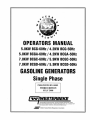
OPERATORS MANUAL
5.0KW BCG-60Hz / 4.2KW
5.0KW BCGA-60Hz / 4.2KW
7.0KW BCGC-60Hz /5.9KW
7.0KW BCGO-60Hz / 5.9KW
BCG-50Hz
BCGA-50Hz
BCGC-50Hz
BCGO-50Hz
GASOLINE GENERATORS
Single Phase
PUBLICATION NO. 46983
THIRD EDITION
JULy 2008
~
WESTERBEKE
WESTERBEKE CORPORATION · MYLES STANDISH INDUSTRIAL PARK
150 JOHN HANCOCK ROAD · TAUNTON MA 02780·7319 · TEL , (508)823-7677
FAX (508)884-9688 · WEBSITE: WWW.WESTERBEK£.COM
,tfJM,T
Member Nai/Oiral Marin e Manufaclurers Associfllion
.w
d
Gasoline with an ETHANOL content
higher than 10% (E10) is not allowed
and may void warranty.
Engines & Generators
CALIFORNIA PROPOSITION 65
WARNING
Exhaust gas from diesel and
gasoline engines (and some of
its constituents) are known to
the State of California to cause
cancer, birth defects, and other
reproductive harm.
A WARNING:
Exhaust gasses contain Carbon Monoxide, an odorless and
colorless gas. Carbon Monoxide is poisonous and can cause
unconsciousness and death. Symptoms of Carbon Monoxide
exposure can include:
-Dizziness
- Throbbing in Temples
-Nausea
- Muscular Twitching
-Headache
- Vomiting
- Weakness and Sleepiness -Inability to Think Coherently
IF YOU DR ANYONE ELSE EXPERIENCE ANY OF THESE SYMPTOMS,
GET DUT INTO THE FRESH AIR IMMEDIATELY. If symptoms persist,
seek medical attention. Shut down the unit and do not restart
until it has been inspected and repaired.
A WARNING DECAL is provided by WESTERBEKE and
should be fixed to a bulkhead near your engine or
generator.
WESTERBEKE also recommends installing CARBON
MDNOXIDE DETECTORS in the living/sleeping quarters
of your vessel. They are inexpensive and easily
obtainable at your local marine store.
Engines & Generators
SAFETY INSTRUCTIONS
PREVENT BURNS - FIRE
INTRODUCTION
Read this safety manual carefully. Most accidents are
caused by failure to follow fundamental rules and precautions. Know when dangerous conditions exist and take the
necessary precautions to protect yourself, your personnel,
and your machinery.
The following safety instructions are in compliance with
the American Boat and Yacht Council (ABYC) standards.
•
PREVENT ELECTRIC SHOCK
•
A WARNING: 00 not touch AC electrical connectlDRS
while engine is running, or when connected to shore
power. Lethal voltage is present at these cDnnectiDns!
•
Do not operate this machinery without electrical
enclosures and covers in place.
•
Shut off electrical power before accessing electrical
equipment.
Use insulated mats whenever working on electrical
equipment.
Make sure your clothing and skin are dry, not damp
(particularly shoes) when handling electrical equipment.
Remove wristwatch and all jewelry when working on
electrical equipment.
Do not connect utility shore power to vessel's AC
circuits, except through a ship-to-shore double throw
transfer switch. Damage to vessel's AC generator may
result if this procedure is not followed.
Electrical shock results from handling a charged capacitor. Discharge capacitor by shorting tenninals together.
•
•
•
•
•
A WARNING: Fire can cause injury Df death/
•
•
•
injury or death/
•
Follow re-fueling safety instructions. Keep the vesseFs
hatches closed when fueling. Open and ventilate cabin
after fueling. Check below for fumes/vapor before running the blower. Run the blower for four minutes before
starting your engine.
•
All fuel vapors are highly explosive. Use extreme care
when handling and storing fuels. Store fuel in a well-ventilated area away from spark-producing equipment and
out of the reach of children.
Do not fill the fuel tank(s) while the engine is running.
Shut off the fuel service valve at the engine when servicing
the fuel system. Take care in catching any fuel that might
spill. DO NOT allow any smoking, open flames, or other
sources of fire near the fuel system or engine when servicing. Ensure proper ventilation exists when servicing the
fuel system.
Do not alter or modify the fuel system.
Be sure all fuel supplies have a positive shutoff valve.
Be certain fuel line fittings are adequately tightened and
free of leaks.
Make sure a fire extinguisher is installed nearby and is
properly maintained. Be familiar with its proper use.
Extinguishers rated ABC by the NFPA are appropriate
for all applications encountered in this environment.
•
•
Always check the engine coolant level at the coolant
recovery tank.
•
•
•
A WARNING: Steam can cause injury Of death!
•
In case of an engine overheat, allow the engine to cool
before touching the engine or checking the coolant.
diesel fuel will bum.
A WARNING: ExplosiDns from fuel vapors can cause
exhaust system components. Arunning engine gets
very hot!
•
Be aware
PREVENT BURNS - EXPLOSION
PREVENT BURNS - HOT ENGINE
A WARNING: OD not touch hot engine parts Of
Prevent flash fires. Do not smoke or pennit flames or
sparks to occur near the carburetor, fuel line, filter, fuel
pump, or other potential sources of spilled fuel or fuel
vapors. Use a suitable container to catch all fuel when
removing the fuel line, carburetor, or fuel filters.
Do not operate with a Coast Guard Approved flame
arrester removed. Backfire can cause severe injury or
death.
Do not operate with the air cleaner/silencer removed.
Backfire can cause severe injury or death.
Do not smoke or pennit flames or sparks to occur near
the fuel system. Keep the compartment and the
engine/generator clean and free of debris to minimize the
chances of fire. Wipe up all spilled fuel and engine oil.
•
Engines & Generators
SAFETY INSTRUCTIONS
ACCIDENTAL STARTING
TOXIC EXHAUST GASES
A WARNING: Accidental starting can cause injury
A WARNING: Carbon monoxide (CO) Is a deadly gas!
ordeathJ
•
Ensure that the exhaust system is adequate to expel gases
discharged from the engine. Check the exhaust system
regularly for leaks and make sure the exhaust manifoldl
water-injected elbow is securely attached.
• Be sure the unit and its surroundings are well ventilated.
Run blowers when running the generator set or engine.
• Don't run the generator set or engine unless the bo~t is
equipped with a functioning marine carbon monoXlde
detector that complies with ABYCA-24. Consult your boat
builder or dealer for installation of approved detectors.
• For additional information refer to ABYC T-22
(educational information on Carbon Monoxide).
•
Disconnect the battery cables before servicing the engine!
generator. Remove the negative lead first and reconnect
it last.
• Make certain all personnel are clear of the engine before
starting.
• Make certain all covers, guards, and hatches are reinstalled before starting the engine.
BATTERY EXPLOSION
A WARNING: Battery explosion can cause injury
or death!
A WARNING: Carbon monoxide {CO} is an invisible
•
Do not smoke or allow an open flame near the battery
being serviced. Lead acid batteries emit hydrogen, a
highly explosive gas, which can be ignited by elect~ical
arcing or by lit tobacco products. Shut off all electncal
equipment in the vicinity to prevent electrical arcing during servicing.
• Never connect the negative (-) battery cable to the positive (+) connection terminal of the starter solenoid. Do
not test the battery condition by shorting the terminals
together. Sparks ~ould ignite battery gases or fuel vapors.
Ventilate any compartment containing batteries to prevent
accumulation of explosive gases. To avoid sparks, do not
disturb the battery charg0r connections while the battery
is being charged.
• Avoid contacting the terminals with tools, etc., to prevent
bums or sparks that could cause an explosion. Remove
wristwatch, rings, and any other jewelry before handling
the battery.
• Always tum the battery charger off before disconnecting
the battery connections. Remove the negative lead first
and reconnect it last whenservicing the battery.
odorless gas. Inhalation produces flu-like symptoms,
nausea or death!
•
Do not use copper tubing in diesel exhaust systems. Diesel
fumes can rapidly destroy copper tubing in exhaust systt:ms.
Exhaust sulfur causes rapid deterioration of copper tubmg
resulting in exhaust/water leakage.
• Do not install exhaust outlet where exhaust can be drawn
through portholes, vents, or air conditioners. If the engine
exhaust discharge outlet is near the waterline, water could
enter the exhaust discharge outlet and close or restrict the
flow of exhaust. Avoid overloading the craft.
• Although diesel engine exhaust gases are not as toxic as
exhaust fumes from gasoline engines, carbon monoxide
gas is present in diesel exhaust fumes. Some of the
symptoms or signs of carbon monoxide inhalation or
poisoning are:
Vomiting
Inability to think coherently
Dizziness
Throbbing in temples
Headache
Muscular twitching
Nausea
Weakness and sleepiness
BATTERY ACID
AVOID MOVING PARTS
A WARNING: Sulfuric acid in batteries can cause
A WARNING: Rotating parts can cause injury
severe injury or death!
•
or death!
When servicing the battery or checking the electrolyte
level. wear rubber gloves. a rubber apron, and eye protection. Batteries contain sulfuric acid which is destructive.
If it comes in contact with your skin, wash it off at once
with water. Acid may splash on the skin or into the eyes
inadvertently when removing electrolyte caps.
• Do not service the engine while it is running. If a situation
arises in which it is absolutely necessary to make operating adjustments, use extreme care to avoid touching moving parts and hot exhaust system components.
Engines & Generators
ii
SAFETY INSTRUCTIONS
•
ABYC, NFPA AND USCG PUBLICATIONS FOR
INSTALLING DIESEL ENGINES
Do not wear loose clothing or jewelry when servicing
equipment; tie back long hair and avoid wearing loose
jackets, shirts, sleeves, rings, necklaces or bracelets that
could be caught in moving parts.
•
Make sure all attaching hardware is properly tightened.
Keep protective shields and guards in their respective
places at all times.
•
Do not check fluid levels or the drive belt's tension while
the engine is operating.
•
Stay clear of the drive shaft and the transmission coupling
when the engine is ruuning; hair and clothing can easily
be caught in these rotating parts.
Read the following ABYC, NFPA and USCG publications
for safety codes and standards. Follow their recommendations when installing your engine.
ABYC (American Boat and Yacht Council)
"Safety Standards for Small Craft"
Order from:
ABYC
3069 Solomon's Island Rd.
Edgewater, MD 21037
NFPA (National Fire Protection Association)
"Fire Protection Standard for Motor Craft"
HAZARDOUS NOISE
Order from:
A WARNING: High noise levels can cause hearing
NFPA
11 Tracy Drive
Avon Industrial Park
Avon, MA 02322
loss!
•
Never operate an engine without its muffler installed.
•
Do not run an engine with the air intake (silencer)
removed.
•
Do not run engines for long periods with their enclosures
open.
USCG (United States Coast Guard)
"USCG 33CFR183"
Order from:
U.S. Govemment Printing Office
Washington, D.C. 20404
A WARNING: Do not work on machinery when you are
mentally Dr physically incapacitated by fatigue!
OPERATORS MANUAL
Many of the preceding safety tips and warnings are repeated
in your Operators Manual along with other cautions and
notes to highlight critical information. Read your manual
carefully, maintain your equipment, and follow all safety
procedures.
ENGINE INSTALLATIONS
Preparations to install an engine should begin with a thorough examination of the American Boat and Yacht Council's
(ABYC) standards. These standards are a combination of
sources including the USCG and the NFPA.
Sections of the ABYC standards of particular interest are:
H-2 Ventilation
P-l Exhaust systems
P-4 Inboard engines
E-9 DC Electrical systems
All installations must comply with the Federal Code of
Regulations (FCR).
Engines & Generators
iii
INSTALLATION
When installing WES1ERBEKE engines and generators it is important that strict
attention be paid to the following information:
CODES AND REGULATIONS
Strict federal regulations, ABYC guidelines, and safety codes must he complied with
when installing engines and generators in a marine environment.
SIPHON-BREAK
For installations where the exhaust manifold/water injected exhaust elbow is close to
or will be below the vessel's waterline, provisions must be made to install a siphonbreak in the raw water supply hose to the exhaust elbow. This hose must he looped a
minimum of 20" above the vessel's waterline. Failure to use a siphon-break when
the exhaust manifold injection pOri is at or below the load waterline will result in
raw water damage to the engine and possible flooding of the boat.
If you have any doubt about the position of the water-injected exhaust elbow relative
to the vessel's waterline under the vessel's various operating conditions, install a
siphon-break.
NOTE: A siphon-break requires periodic inspection and cleaning to ensure proper
operation. Failure to properly maintain a siphon-break can result in catastrophic
engine damage. Consult the siphon-break manufacturer for proper maintenance.
EXHAUST SYSTEM
The exhaust hose must he certified for marine use. The system must be designed to
prevent water from entering the exhaust under any sea conditions and at any angle
of the vessels hulL
Engines & Generators
iv
TABLE OF CONTENTS
Introduction .........................................................................2
Fuel, Engine Oil and Engine Coolant.. ............................... .4
Control Panels .................................................................;... 5
Preparations for Initial Start-Up .........................................6
Operating Instructions ........................................................7
Remote Panel ......................................................................8
Break-in Procedure/Daily Operation ...................................9
Safety Shutdown Switches................................................ 10
Maintenance Schedule ..................................................... 11
Cooling System .................................................................. 13
Changing Coolant.. ..................................................... 13
Thermostat .................................................................. 14
Zinc Anode ................................................................. 14
Raw Water Strainer .................................................... 15
Raw Water Pump ........................................................ 15
Fuel System ....................................................................... 16
GasolinelWater Separator ........................................... 16
Fuel Filter ................................................................... 16
Engine Oil .........................................................................17
Oil Change ................................................................. 17
Battery Charging Circuit ................................................... 18
Electronic Governor ..........................................................19
Troubleshooting The Electronic Governor ........................20
Carburetor Adjustments ....................................................21
Engine Adjustments ..........................................................22
Timing Belt .............................................................. ,.22
Compression Test ....................................................... 22
Valve Clearance .......................................................... 26
Injection Timing ......................................................... 26
Torquing The Cylinder Head Bolts ............................ 26
Spark Plugs .................................................................27
Drive Belt Adjustment ............................................... 27
Choke Solenoid .......................................................... 27
Generator Information .......................................................28
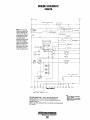
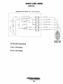
Generator Wiring Schematic ............................................ .29
BCGA AC Terminal Connections ........................................29
BCG AC Terminal Connections ..........................................29 A
BCG Generator Wiring Schematic .....................................29A
Shore Power Transfer SWitch ............................................30
BC Generator Single Phase ...............................................31
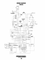
Wiring Schematic (#46876) ............................................. .32
Wiring Diagram (#46876) .................................................. 33
Remote Panel Wiring ........................................................34
Engine Troubleshooting .....................................................35
Lay-up and Recommissioning ...........................................37
Specifications....................................................................39
Specifications....................................................................39 A
Hardware Torques ..............................................................40
Metric Conversions .........................................................:.41
Suggested Spare Parts ......................................................42
Engines & Generators
1
INTRODUCTION
WESTERBEKE CANNOT BE RESPONSIBLE FOR THE CONTENT
OF SUCH SOFTWARE, MAKES NO WARRANTIES OR REPRESENTATIONS WITH RESPECT THERETO, INCLUDING ACCURACY, TIMEUNESS OR COMPLETENESS THEREDF AND WIU
IN NO EVENT BE UABLE FOR ANY TYPE OF DAMAGE OR
INJURY INCURRED IN CONNECTION WITH OR ARISING OUT OF
THE FURNISHING OR USE OF SUCH SOFTWARE.
WESTERBEKE customers should also keep in mind the time
span between printings of WESTERBEKE product software
and the unavoidable existence of earlier WESTERBEKE
manuals. In summation, product software provided with
WESTERBEKE products, whether from WESTERBEKE or
other suppliers, must not and cannot be relied upon exclusively as the definitive authority on the respective product. It
not only makes good sense but is imperative that appropriate
representatives of WESTERBEKE or the supplier in question
be consulted to determine the aceuracy and currentness of the
product software being consulted by the customer.
This WESTERBEKE Generator is a product of
WESTERBEKE'S long years of experience and advanced
technology. We take great pride in the superior durability and
(jependable performance of our engines and generators.
Thank you for selecting WESTERBEKE.
In order to get the full use and benefit from your generator,
it is important that you operate and maintain it correctly. This
manual is designed to help you do this. Please read this
manual carefully and observe all the safety precautions
throughout. Should your engine require servicing, contact
your nearest WESTERBEKE dealer for assistance.
This is your Operators Manual. A PaIts Catalog is also
provided and a Technical Manual is available from your
WESTERBEKE dealer. Also, if you are planning to install
this equipment yourself, contact your WESTERBEKE dealer
for WESTERBEKE'S Installation ManuaL
WARRANTY PROCEDURES
Your WESTERBEKE Warranty is included in a separate
folder. If you have not received a customer identification
caI·d registering your WaITanty 60 days after submitting the
WaITanty registration form, please contact the factory in
writing with model infonnation, including the unit's serial
number and commission date.
LOCATION~~
SERIAL NUMBER
The engine serial
Fill in the information
~h:;olQ'f,..~· ryumber is s~am[Jed
below for reference. /;::/:v
~ j' rnto the engrne block.
/..:/"~'
lY
~
f'"
,.."."WESTERBEKE
, Engines & Generators
Customer Identification
The engine model
number and serial
number are printed
on a decal on the
engine manifold.
WESTERBEKE OWNER
MAIN STREET
HOMETOWN, USA
Model
Expires
The generator serial
number is stamped
on the top of the
generator HIII,'_YI.rLfJ
Ser. #
Customer Identification Card (Typical)
are
on a decal
on the side of the
generator.
The WESTERBEKE serial number is an alphanumeric
number that can assist in determining the date of
manufacture of your WESTERBEKE engine/generator. The
first character indicates the decade (A=1960s, B=1970s,
C=1980s, D=1990s E=2000s), the first number represents the
year in the decade, and the second and third numbers
represent the month of manufacture.
PRODUCT SOFTWARE
Product software, (tech data, parts lists, manuals, brochures
and catalogs), provided from sources other than WESTERBEKE are not within WESTERBEKE'S CONTROL.
Engines & Generators
2
.,
ibli
"%;11L
INTRODUCTION
ORDERING PARTS
PROTECTING YOUR INVESTMENT
Whenever replacement parts are needed, always provide the
generator and engine model and serial numbers. In addition,
include a complete part description and p(Ut number for each
part needed (see the separately furnished Parts Catalog). Also
insist upon WESTERBEKE packaged parts because will fit
or generic parts are frequently not made to the same specifications as original equipment.
Care at the factory during assembly and thorough testing
have resulted in a WESTERBEKE generator capable of
many thousands of hours of dependable service. However the
manufacturer cannot control how or where the generator is
installed in the vessel or the manner in which the unit is
operated and serviced in the field. This is up to the
buyer/owner-operator.
NOTE: Six important steps to ensure long generator life:
NOTES, CAUTIONS AND WARNINGS
• Proper engine and generator installation and alignment.
As this manual takes you through the operating procedures,
maintenance schedules, and troubleshooting of your generator, critical information will be highlighted by NOTES,
CAUTIONS, and WARNINGS. An explanation follows:
• An efficient well-designed exhaust system that includes
an anti-siphon break to prevent water from entering the
engine.
NOTE: An operating procedure essential to note.
• Changing the engine oil and oil filters every 100 operating hours.
A
• Proper maintenance of aIL engine and generator components according to the maintenance schedule in this
manual.
CAUTION: Procedures, which if not strictly
observed, can result in the damage or destruction of
the engine or generator.
• Use clean, filtered UIlleaded fueL
• 'Winterize your engine according to the "lAy-up and
Recommissioning" section in this manual.
A
WARNING: Procedures, which if not properly
followed. can result in personal injury or loss of life.
UNDERSTANDING THE GASOLINE GENERATOR
The gasoline engine driving an AC generator is in many
ways similar to a gasoline automobile engine. The cylinders
are verticle in-line, and the engine's cylinder head has an
overhead camshaft which is chain-driven. The engine utilizes
a solid-state distributor which is horizontally mounted and
camshaft-driven. The engine incorporates a pressure type
lubrication system, and a fresh water-cooled engine block
which is thermostatically-controlled. To a large degree, the
generator's engine requires the same preventive maintenance
that is required of a gasoline automobile engine. The most
important factors to the generator's longevity are proper
ventilation, maintenance of the fuel system, ignition system,
cooling system and the generator backend.
NOTE: A carbon monoxide warning decal has been provided
by WESTERBEKE. Affix this decal in a visable location in
the engine room.
SPARES AND ACCESSORIES
Certain spare parts will be needed to support and maintain
your WESTERBEKE generator or engine when cruising (see
SUGGESTED SPARE PARTS). Often even simple items such
as proper fuel and oil filter can be difficult to obtain along
the way. WESTERBEKE will provide you with a suggested
spares and accessories brochure to assist you in preparing an
on-board inventory of the proper WESTERBEKE parts.
Engines & Generators
3
FUEL, ENGINE OIL AND ENGINE COOLANT
CARE OF THE FUEL SUPPLY
A
ENGINE COOLANT
Westerbeke recommends a mixture of 50% antifreeze and
50% distilled water, when possible. Distilled water is free
from the chemicals that can corrode internal engine surfaces.
CAUTION: Only use unleaded fuel with an
octane rating of 89 or higher. Leaded fuel will cause
serious harm to your engine and riolate your warranty.
The antifreeze performs double duty, as it allows the engine
to run at proper temperatures by transferring heat away from
the engine to the coolant. It also lubriciltes and protects the
cooling circuit from rust and corrosion. Use a good quality
antifreeze that contains supplemental cooling additives
(SeAs) that keep the antifreeze chemically balanced, crucial
to long tenn protection.
Use only clean fuel! It is important to buy clean fuel, and
keep it clean. The best fuel can be rendered unsatisfactory by
careless handling or improper storage facilities. To assure that
the fuel going into the tank for your engine's daily use is
clean and pure, the following practice is advisable:
Purchase a well-known brand of fuel.
The water and antifreeze should be pre-mixed before being
poured into the cooling circuit.
Install and regularly service a good, Coast Guard approved
metal bowl type filter/water separator between the fuel tank
and the engine.
NOTE: Use the new environmentally{riendly long lasting
antifreeze that is now available.
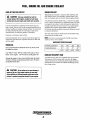
ANTIFREEZE PROTECTION CHART
ENGINE OIL
Antifreeze concentration
23%
30%
35%
50%
Use a good well known brand of oil and try to stay with
the brand you select.
Freezing Temperature
14° F
8° F
-4°F
-40° F
(-10 oG)
(-13°C)
(·20oG)
Use "ONLY" SAE 40W oil with an API code of SJ or
better in this engine. Do Not use any multi grade oils.
COOLANT RECOVERY TANK
A coolant recovery tank kit is supplied with each generator.
The purpose of this recovery tank is to allow for engine
coolant expansion and contraction during engine operation,
without the loss of coolant and without introducing air into
the cooling system.
Change the engine's lube oil and oil filter after the initial
50 hours of break-in operation and then every 100 hours
of operation there after.
A
(-40°C)
CAUTION: Do not allow two or more brands of
engine oil to mix. Each brand contains its own additires; additives of different brands could react in the
mixture to produce properties harmful to your engine.
Engines & Generators
4,
CONTROL PANELS
GENERATOR CONTROL PANEL
REMOTE PANEL
The ON and START/STOP switches are the only functional
components to operate the generator at the engine. Both
switches are used to start the generator - see Starting the
Generator under OPERATING INSTRUCTIONS.
There are three functional components on the remote panel
for generator operation:
The ON switch is a two-position switch with momentary
contacts in the up (on) position and a stationary contact
function in the center position. This switch energizes the
fuel pump.
1. START/STOP switch
1. ON switch
2. Green LED indicator light
The ON switch is a two-position switch with momentary
contacts in the up (on) position and a stationary contact
function in the center PQsition. This switch energizes the
fuel pump.
The START/STOP switch is a three-position switch with
momentary contacts in the up (start) position and a stationary
contact function in the center and down (stop) positions. The
center (normal) position allows the generator to be run, once
started, and also enables the remote panel(s) to control the
start/stop functions. The up (start) position starts the generator
and once released, reverts to the center position. The down
(stop) position stops the engine in nonnal operation as well
as in an emergency situation, as it opens the K2 relay which
de-energizes the run circuit and shuts down the engine
(unlike the remote panel stop switch) controls power to the
starter, fuel pump, and ignition relay coils, thus stopping the
engine should a malfunction occur. During times when
maintenance is being performed on the generator, the
START/OFF switch should be placed in the stationary (off)
position. This will disable the remote control panel(s), preventing attempts to start the generator from their locations.
However, it is always best to remove the Fl fuse to prevent
accidental starting .
The START/STOP switch is a three-position switch with
momentary contact functions in the up (start) and down
(stop) positions, and a stationary contact function in the
center position The center position i~ a dual OFFIRUN mode
position and is nonnally in the off mode. When in the start
(up) position, this switch starts the generator (together with
the ON switch in the up position) and once released, reverts
to the center position, run mode. When in the stop (down)
position, this switch stops the generator, and once released,
reverts to the center position, off mode.
The Green LED indicator light indicates the engine running
condition. It lights when the ON switch is moved to the start
position, dims when the engine is cranking, and brightens
when the engine starts, notifying the operator to release the
START switch.
~+--IHOUR
METER
RESET BUTTON
ON SWITCH ----IL.lo..J
"",=--~--
START/STOP SWITCH: CENTERED,
THIS SWITCH IS IN THE OFF
POSITION. ONCE THE GENERATOR
IS STARTED, THE CENTER POSITION
BECOMES THE RUN POSITION.
F1 FUSE
REMOTE PANEL
REMOTE PANEL
CONNECTION
I
NOTE: Refer to OPERATING INSTRUCTIONS
in the following pages for the operation
of these panels.
Engines & Generators
:5
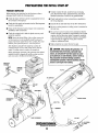
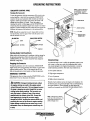
PREPARATIONS FOR INITIAL START-UP
PRESTART INSPECTION
Before starting your generator for the first time or after a
prolonged layoff, check the following items:
• Visually examine the unit. Look for loose or missing
parts, disconnected wires, unattached hoses, and check
threaded connections. Search for any gasoline leaks.
• Check the engine oil level: add oil to maintain the level at
the full mark on the dipstick.
• Check load leads for correct connections as specified in
the wiring diagrams.
• Check the fuel supply and examine the fuel filter/separator
bowls for contaminants.
• Examine the air inlet and outlet for air flow obstructions.
• Be sure no other generator or utility power is connected to
the load lines.
• Check the DC electrical system. Inspect wire connections
and battery cable connections.
• Be sure that in power systems with a neutral line that the
neutral is properly grounded (or ungrounded) as the system
requires, and that generator neutral is properly connected
to the load neutral. In single phase systems an incomplete
or open neutral can supply the wrong line-to-neutral
voltage on unbalanced loads.
• Check the coolant level in both the plastic recovery tank
and at the manifold.
NOTE: During the initial filling of the cooling system, the
air bleed petcock on the manifold should be opened to
purge air from the engine block. Once coolant, free of air
bubbles, flows from the petcock close the petcock.
• Make certain the raw water thru-hull is open.
After shutdown and after the engine has cooled, the
coolant from the recovery tank will be drawn into the
engine's cooling system to replace the purged air.
A CAUTION:
When starling the generator, it is
recommended that all AC loads. especially large
motors, be switched OFF until the engine has come
up to speed and. in cold climates, starts to warm up_
This precaution will prevent damage caused by
unanticipated operation of the AC machinery and will
prevent a cold engine from stalling.
Before subsequent operation of the generator, the engine's
manifold should be topped off, and the coolant recovery
tank may need to be filled to the MAX level;
AIR BLEED
PETCOCK
ZINC ANODE
\
I
ROCKER COVER
THERMOSTAT
HOUSING
MAX. FULL
-MINIMUM
HEAT EXCHANGER
Engines & Generators
6
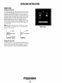
OPERATING INSTRUCTIONS
NOTE: A CIRCUIT BREAKER
IS LOCATED ON THE 510£
Of TH£ PANfLSHUTS
DOWN THE AC GENERATOR
CIRCUIT.
GENERATOR CONTROL PANEL
Starting the Generator
To start the generator, hold the momentary ON switch in the
up (on) position, then hold the momentary START/STOP
switch in the up (start) position (both switches are held up
together). After approximately one second, the starter will
engage and the engine will crank . Once the engine is
running, the starter will disengage, and the START/STOP
switch may then be released to return to its center (run mode)
position. Continue holding the ON switch until the engine has
sufficient oil pressure, then release it 10 its center position.
-HOUR METER
RESET BunON
Fl FUSE
NOTE: Should the engine fail to start, release both switches.
'Wail 20 seconds. and try again. Never run the starter more
than 20 seconds at a rime.
REMOTE PANEL
CONNECTION
START/STOP SWITCH
ON SWITCH
START
OFF/RUN
/START/STOP
/"':. .......SWITCH
.......
I
Starting Under Cold Conditions
Make certain the lubricating oil is conforms with the ratings for
the prevailing temperature. Check the table under ENGINE
LUBRICATING OIL The battery should be fully charged to
minimize voltage drop.
Abnormal Stop
An abnormal stop is one in which the generator ceases to run
and comes to a stop as a result of ah operating fault which
may cause damage to the engine, the generator, or create an
unsafe operating condition. The fault stop conditions are:
Stopping the Generator
To stop the generator, move the momentary START/STOP
switch to the down (stop) position then release it to the center
(ojJlrun mode) position. This will de-energize the K2 run
relay in the generators control panel and stop the generator.
1. Over speed condition.
EMERGENCY STOPPING
2. High engine temperature.
If the generator does not stop using the START/STOP switch,
remove the FI fuse or disconnect the bartery.
3. Low oil pressure.
4. High exhaust temperature.
Should a fault condition occur, the engine will shutdown. On
the remote panel, the green LED light will tum off indicating
an engine shutdown. Once detected, the fault should be
located and corrected (see ENGINE TROUBLESHOOTING).
A CAUTION: Prolonged cranking intervals without
the engine starting can result in the engine exhaust
system filling with raw water. This may happen because
the pump is pumping raw water through the raw water
cooling system during cranking. This raw water can
enter the engine's cylinders by way of the exhaust
manifold once the exhaust system fills. Prevent this
from happening by closing the raw water supply
through.hull shutoff, draining the exhaust muffler, and
correcting the cause of the excessive engine cranking.
Engine damage resulting from raw water entry is not a
warrantable issue; the owner/operator should keep this
in mind.
NOTE: A 30 amp fuse is locared
at (he rear of the control box. This
fuse prOVides protection for the
battery chargmg circuit.
Engines & Generators
7
OPERATING INSTRUCTIONS
REMOTE PANEL
Starting the Generator
To start the generator, hold the momentary ON switch in the
up (on) position (the green light will come on), then hold the
momentary START/STOP switch in the up (start) position
(both switches are held up together). After approximately one
second, the starter will engage and the engine will crank (the
green light will dim). Once the engine is running (the green
light will brighten», the stalter will disengage, and the
START/STOP switch may then be released to return to its
center (run mode) position. Continue holding the ON switch
until the engine has sufficient oil pressure, then release it to
its center position.
NOTE: Sfwuld the engine fail to start, release both switches,
wait 20 seconds, and try again. Never run the starter more
REMOTE PANEL
than 20 seconds at a time.
~~
__ OFF/RUN
11-1.....::_--
OFF/RUN
STOP OFF
START/STOP SWITCH
ON SWITCH
Stopping the Generator
To stop the generator, move the momentary START/STOP
switch to the down (stop) position then release it to the center
(off/run mode) position. This will de-energize the K2 run
relay in the generator's control panel and stop the generator.
Engines &: Generators
8
BREAK-IN PROCEDURE/DAILY OPERATION
NOTE: Some unstable running may occur in a cold engine.
This condition should abate as normal operating temperature
is reached and loads are applied.
BREAK-IN PROCEDURE
After the generator has been started, check for proper operation and then encourage a fast warm-up. Run the generator
between 20% to 60% of full load for the first 10 hours.
A CAUTION:
A CAUTION: Do not operate the generator for long
periods of time without a load being placed on the
generator.
Do not attempt to break-in your genera-
tor by running without a load.
After the first 10 hours of the generators' operation, the load
can be increased to the full-load rated output; then periodically vary the load.
STOPPING THE GENERATOR
Remove the major AC loads from the generator one at a time.
Allow the generator to run for a few minutes to stabilize the
operating temperature and press the STOP switch down, (see
CONTROL PANELS).
Avoid overload at all times. An overload is signaled by a
smoky exhaust with reduced output voltage and frequency.
Monitor the current being drawn from the generator and keep
it within the generators' rating. Since the generator operates
at 1800 rpm to produce 60 hertz, or at 1500 rpm to produce
50 hertz, control of the generator's engine break-in is governed by the current drawn from the generator.
NOTE: After the first 50 hours of generator operation check
the maintenance schedule for the 50 hour service check.
GENERATOR ADJUSTMENTS
Once the generator has been placed in operation, there may
be governor adjustments required for engine speed (hertz)
during the engine's break-in period (first 50 hours) or after
this period (see ENGINE SPEED (HER1Z) ADJUSTMENT
under ENGINE ADJUSTMENTS. A no-load voltage adjustment may also be required in conjunction with the engine's
speed adjustment (see GENERATOR INFORMATION).
To protect against unintentional overloading of the generator,
the generator's output leads should be routed through a circuit breaker that is rated at the rated output of the generator.
NOTE: Be aware of motor starting loads and the high
current drawn required for starting motors. This starting
amperage drawn can be 3 to 5 times normal running amperage. See GENERATOR INFORMATION in this manual.
CHECK LIST
Follow this checklist each day before starting your generator.
• Record the hourmeter reading in your log (engine hours
relate to the maintenance schedule).
• Visually inspect the engine for fuel, oil, or water leaks.
• Check the oil level (dipstick).
• Check the coolant level in the coolant recovery tank.
• Check your fuel supply.
• Check the starting batteries (weekly).
• Check the drive belt for wear and proper tension (weekly).
• Check for abnormal noise such as knocking, vibration and
blow-back sounds.
• Confirm exhaust smoke:
When the engine is cold - White Smoke.
When the engine is warm almost Smokeless.
When the engine is overloaded - some Black Smoke.
Engines & Generators
9
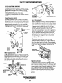
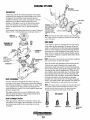
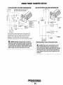
SAFETY SHUTDOWN SWITCHES
SAFETY SHUTDOWN SWITCHES
The engine is protected by a variety of shutdown switches.
Should a shutdown occur. do not attempt to restart withqut
finding and correcting the cause. Refer to the heading
Engine slarts, runs and then shuts down in the ENGINE
TROUBLESHOOTING section of this manual.
The following is a description of these automatic shutdown
switches:
OIL FILTER
ASSEMBLY
Exhaust Temperature Switch
An exhaust temperature switch is located on the exhaust
elbow. Nonnally closed, this switch will open and interrupt
the DC voltage to the K2-run relay (shutting off the engine)
should the switch's sensor indicate an excessive exhaust temperature (an inadequate supply of raw water causes high
exhaust temperatures). This switch opens at 260-270"F (127132°C). This switch resets at approximately 225"F (I07"C).
EXHAUST
ELBOW
Oil PRESSURE SWITCHES
low Oil Pressure Switch
Dual low oil pressure switches are located off the engine's oil
gallery manifold. One is nonnally open when the engine is in
a static stale. This switch functions in the automatic shutdown
circuit when the unit is operating (5 psi rating). The second
oil pressure switch is installed only on SEA RAY spec.
generators. This switch is nonnally closed and functions in
their low oil pressure alarm system (10 psi rating).
Should the oil pressure drop to 10 psi while the generator is
operating, the SEA RAY spec. switch will close activating
their low oil pressure alarm. Should the oil pressure drop
further to 5 psi, the automatic shutdown circuit switch will
open interupting DC voltage to the K2 run relay thereby
shutting off the generator.
High RPM Shutdown Switch
An overspeed switch in the DC circuit shuts off the
generators engine by interupting DC voltage to the K2 run
relay if the engine's speed runs to high. After correcting the
problem, this switch can be reset by momentarily depressing
the stop switch. Refer to the WIRING DIAGRAMS in this
manual.
EXHAUST
TEMPERATURE
SWITCH
OVERSPEED
CIRCUIT BOARD
Waler Temperature Switch
A high water temperature switch is located at the thennostat
housing. Nonnally closed, this switch, should the fresh water
coolant's operating temperature reach approximately 210°F
(99°C), will open and interrupt the DC voltage to the K2 run
relay therebyshutting off the engine. This switch resets at
195"F (107"C).
Engine Circuit Breaker
The generator's engine is protected by an engine mounted
manual reset circuit breaker (20 amps DC). Excessive current
draw or electrical overload anywhere in the instrument panel
wiring or engine wiring will cause the breaker to trip. In this
event the generator will shut down because the opened
breaker interrupts the DC circuit to the K2-run relay. If this
should occur, check and repair the source of the problem.
After repruring the fault. reset the breaker and restart the
generator.
WATER (COOLANT)
TEMPERATURE
SWITCH
Engines & Generators
10
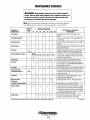
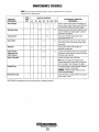
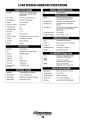
MAINTENANCE SCHEDULE
A WARNING: Neller attempt to perform any scfllice while the engine is
running. Wear the proper safety equipment such as goggles and gloves, and
use the correct tools for each job. Disconnect the battery terminals when
sefllicing any of the engine's DC electrical equipment.
NOTE: Many of the following maintenance procedures are simple but others are
more difficult and may require the expert knowledge of a service mechanic.
SCHEDULED
MAINTENANCE
CHECK
EACH
DAY
HOURS OF OPERATION
50
100
250
500
750 1000 1250
EXPLANATION OF SCHEDULED
MAINTENANCE
Fuel Supply
0
Unleaded gasoline with octane rating of 89 or
higher.
Fuel/Water Separator
0
Check for water and dirt in fuel (drain/replace filter
if necessary).
Engine Oil level
0
Oil level should indicate between FULL and LOW on
dipstick.
Coolant Level
0
Check at recovery tank; if empty, check at manifold.
Add coolant if needed.
0
Inspect for proper tension (3/8" to 1/2" deflection)
and adjust if needed. Check belt edges for wear.
Drive Belt
weekly
Visual Inspection 01 Engine
0
NOTE: Keep engine surface clean. Dirt and
oil will inhibit the engine s ability to remain
cool.
Spark Plugs
[j
Generator
0
Fuel Filter
::::J
Starting Batteries
(and House Batteries)
Engine Oil
*Adjust the Valve
Clearances
0
0
0
0
0
0
0
0
0
0
0
0
0
0
0
0
0
0
0
0
Exhaust System
::::J
Check gap; inspect for burning and corrosion.
Check that AC connections are clean and secure
with no chafing - see GENERATOR INFORMATION
for additional information.
Initial change at 50 hrs, then change every 250 hrs.
Every 50 operating hours check electrolyte levels
and make sure connections are very tight. Clean off
excessive corrosion.
weekly
Air Screen (Flame Arrester)
Engine Hoses
0
0
0
Check for fuel, oil and water leaks. Inspect wiring
and electrical connections. Keep bolts &nuts tight.
Check for loose belt tension.
0
0
0
0
0
Initial engine oil & filter change at 50 hrs., then
change both every 100 hours.
Initial adjustment at 50 hrs., then every 500 hrs.
Clean at 50 hours, then every 100 hours.
0
0
c:::
~D
0
0
0
Initial check at 50 hrs., then every 250 hrs. Inspect
for leaks. Check siphon brake operation. Check the
exhaust elbow for carbon and/or corrosion buildup
on inside passages; clean and replace as necessary.
Check that all connections are tight.
0
Hose should be hard & tight. Replace if soft or
spongy. Check and tighten all hose clamps.
*WESTERBEKE recommends this service be performed by an authorized mechanic.
Engines & Generators
11
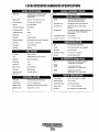
(continued)
MAINTENANCE SCHEDULE
NOTE: Use the engine hounneter gauge to log your engine hours or record your
engine hours by running time.
SCHEDULED
MAINTENANCE
Heat Exchanger
CHECK
EACH
DAY
HOURS OF OPERATION
50
100
250
500
:::J
0
0
0
0
*Starter Motor
Clean or replace anode. Open heat exchanger end
cap and clean out debris. Remove every 1000 hours
for professional cleaning and pressure testing.
0
Remove pump cover and inspect impeller for wear;
replace if needed. Also replace gasket. Lubricate
both when reassembling.
Drain, flush, and refill cooling system with
appropriate antifreeze mix.
D
0
D
D
*Engine Timing Belt
[]
Check solenoid and motor for corrosion. Remove
and lubrica,te. Clean and lubricate the start motor
pinion drive.
Check ignition timing. Check condition of
distributor cap and rotor.
D
*Engine Cylinder
Compression and
Valve Clearance
EXPLANATION OF SCHEDULED
MAINTENANCE
0
0
Coolant System
Distributor
0
:::J
0
Raw Water Pump
750 1000 1250
D
Incorrect valve clearance will result in poor engine
performance; check compression pressure and timing,
and adjust valve clearances.
Remove and replace every 1000 hours.
Note: Failure to replace the timing belt at the
recommended interval could result in timing chain
failure resulting in major damage to the engine.
*Exhaust Elbow
Test exhaust elbow for casting integrity. Replace if
casting is corroded or deteriorated.
WARNING: A defective exhaust elbow can cause
carbon monoxide leakagel
D
Carburetor Drip Tray
Inspect and drain at regUlar intervals. Do not allow
fuel to collect in drain.
*WESTERBEKE recommends this service be performed by an authorized mechanic.
Engines & Generators
12
COOLING SYSTEM
FRESH WATER COOLING CIRCUIT
CHANGING COOLANT
NOTE: Refer to the ENGINE COOLANT section for the
recommended antifreeze and water mixture to be used as the
fresh water coolant.
The engine's coolant must be changed according to the
MAINTENANCE SCHEDULE. If the coolant is allowed to
become contaminated, it can lead to overheating problems.
Fresh water coolant is pumped through the engine by a
circulating pump, absorbing heat from the engine. The
coolant then passes through the thermostat into the manifold,
to the heat exchanger where it is cooled, and returned to the
engine block via the suction side of the circulating
pump.When the engine is started cold, external coolant flow
is prevented by the closed thermostat (although some coolant
flow is bypassed around the thermostat to prevent the exhaust
manifold from overheating). As the engine warms up, the
thermostat gradually opens, allowing full flow of the engine's
coolant to flow unrestricted to the external portion of the
cooling system.
A CAUTION: Proper cooling system maintenance is
critical; a substantial number of engine fai/ures can be
traced back to cooling system co"osion.
Drain the engine coolant by removing the drain plug and
opening the manifold pressure cap. Flush the system with
fresh water, then reinstall the drain and start the refill process.
A WARNING: Beware of the hot engine coolant.
Wear protective gloves.
Coolant Recovery Tank
Refilling the Coolant
A coolant recovery tank allows for engine coolant expansion
and contraction during engine operation, without any
significant loss of coolant and without introducing air into
the cooling system. This tank should be located at or above
the engine manifold level and should be ea~ily accessible.
After replacing the engine drain plug, open the air bleed
petcock on the exhaust manifold and slowly pour clean,
premixed coolant into the manifold.
Monitor the coolant in the manifold and add as needed. Fill
the manifold neck. Once coolant begins flowing from the air
bleed petcock free of air bubbles, close the petcock and
install the manifold pressure cap.
Remove the cap on the coolant recovery tank and fill with
coolant mix to halfway between LOW and MAX and replace
the cap. Run the engine and observe the coolant expansion
flow into the recovery tank.
COOLANT RECOVERY
TANK
Mter checking for leaks, stop the engine and allow it to cool.
Coolant should draw back into the cooling system as the
engine cools down. Add coolant to the recovery tank if
needed and check the coolant in the manifold. Clean up any
spilled coolant.
NOTE: Periodically check the condition of the manifold pressure cap. Ensure that the upper and lower rubber seals are in
good condition and check that the vacuum valve opens and
closes tightly. Carry a spare cap.
,-
COOLANT DRAIN
LOCATED JUST BELOW
THE INTAKE MANIFOLD
SEALS
CHECKING THE PRESSURE CAP
FROM COOLANT
RECOVERY TANK
TO COOLANT
RECOVERY TANK
MAKE CERTAIN THESE
PASSAGES ARE KEPT CLEAR
COOLANT RETRACTION
Engines & Generators
13
COOLANT EXPANSION
COOLING SYSTEM
THERMOSTAT
A thermostat controls the coolant temperature as the coolant
continuously flows through the closed cooling circuit. When
the engine is first started the closed thermostat prevents
coolant from flowing (some coolant is by-passed around the
thermostat to prevent the exhaust manifold from overheating). As the engine warms up, the thermostat gradually
opens. The thermostat is accessible and can be checked,
cleaned, or replaced easily. Carry a spare thermostat and
gasket.
If you suspect a faulty thermostat, place it in a pan of water and
bring to a boiL A working thermostat should open about 112"
GASKET
O-RING
WARNING: DO
ALl:.OW WATER TO
INTO THE GENERATOR
HOUSING... COVER
THE AIR FAN INLET
WITH FOIL WHEN
REMOVING THE END
CAP
-
NOTE: Operating in silty and/or tropical waters
requlre
that a heat exchanger cleaning be peifonned more often then
every 1000 hours.
MANIFOLD
PRESSURE CAP
ZINC ANODE
CHANGING THE
THERMOSTAT
A zinc anode (or pencil) is located in the raw water cooling
circuit within the heat exchanger. The purpose of the zinc
anode is to sacrifice itself to electrolysis action taking place
in the raw water cooling circuit, thereby reducing the effects
of electrolysis on other components of the system. The condition of the zinc anode should be checked monthly and the
anode cleaned or replaced, as required. Spare anodes should
be carried onboard.
GASKET
APPLY SEALANT
TO GASKET WHEN-----?1
INSTALLING
NOTE: Electrolysis is the result of each particular installation
and vessel location, not that of the engine.
If the zinc anodes need replacement, hold the hex boss into
THERMOSTAT
Cool raw water flows through the inner tubes of the heat
exchanger. As the engine coolant passes around these tubes the
heat of the internal engine is conducted to the raw water which
is then pumped into the exhaust system and discharged. The
engine coolant (now cooled) flows back though the engine and
the circuit repeats itself.
The engine coolant and raw water are independent of each
other; this keeps the engine's water passages clean from the
harmful deposits found in raw water.
which the zinc anode is'threaded with a wrench while
loosening the anode with another wrench. This prevent~ the
hex boss from possibly tearing off the exchanger shell. After
removing the zinc, note the condition of it. If the zinc is in
poor condition, there are probably alot of zinc flakes within
the exchanger. Remove the end of the heat exchanger and
clean the inside of all zinc debris. Always have a spare heat
exchanger end gasket in case the present one becomes
damaged when removing the end cover. Replace the gasket
(refer to your engine model's heat exchanger end gasket part
number), O-ring and cover, and install a new zinc anode.
NOTE: The threads of the zinc anodes are pipe threads and do
not require sealant. Sealant should not be used as it may
insulate the zinc from the metal of the heat exchanger
housing preventing electrolysis action on the zinc.
ZINC ANODES
Heal Exchanger Service
After approximately 1000 hours of operation, remove, clean
and pressure test the engine's heat exchanger. (A local automotive radiator shop should be able to clean and test the heat
exchanger).
NEW
Engines & Generators
14
THROW OUT
THROW OUT
CLEAN AND
REUSE
COOLING SYSTEM
RAW WATER INTAKE STRAINER
RAW WATER PUMP
NOTE: Always install the strainer at or below the waterline so
The raw water pump is a self-priming, rotary pump with a
non-ferrous housing and a Neoprene impeller. The impeller
has flexible blades which wipe against a curved cam plate
within the impeller housing, producing the pumping action.
On no account should this pump be run dry. There should
always be a spare impeller and impeller cover gasket aboard
(an impeller kit). Raw water pump impeller failures occur
when lubricant (raw water) is not present during engine
operation. Such failures are not warrantable, and operators
are cautioned to make sure raw water flow is present at startup. The raw water pump should be inspected periodically for
broken or tom impeller blades. See MAINTENANCE
SCHEDULE.
the strainer will always be self-priming.
A clean raw water intake strainer is a vital component of the
engine's cooling system. Include a visual inspection of this
strainer when making your periodic engine check. The water
in the glass should be clear.
Perform the following maintenance after every 100 hours of
operation:
1. Close the raw water seacock.
2. Remove and clean the strainer filter.
3. Clean the glass.
4. Replace the washer if necessary.
5. Reassemble and install the strainer.
6. Open the seacock.
NOTE: Should a failure occur with the pump s internal parts
(seals and bearings), it may be more cost efficient to purchase a new pump and rebuild the original pump as a spare.
7. Run the engine and check for leaks.
Changing the Raw Water Pump Impeller
NOTE: Also follow the above procedure after having run hard
Close the raw water intake valve. Remove the pump cover
and, with the aid of two small screwdrivers, carefully pry the
impeller out of the pump. Install the new impeller and gasket.
Move the blades to conform to the curved cam plate and
push the impeller into the pump's housing. When assembling, apply a thin coating of lubricant to the impeller and
gasket. Open the raw water intake valve.
aground.
If the engine temperature gauge ever shows a higher than
normal reading, the cause may be that silt, leaves or grass
may have been caught up in the strainer, slowing the flow of
raw water through tt,le cooling system
~
RAW WATER
PUMP
STRAINER
CAM PLATE
RAW WATER INTAKE STRAJNER
OWNER INSTAlLED (TYPICAL)
APPLY LUBRICANT
OR LIQUID SOAP
AT ASSEMBLY
RAW WATER COOLING CIRCUIT
The raw water flow is created by a positive displacement
impeller pump. This pump draws water directly from the raw
water source (ocean, lake, or river) through a hose to the
water strainer. The raw water passes from the strainer
through the raw water pump to the heat exchanger (through
the heat exchanger tubes) where it cools the engine drculating fresh water coolant. The raw water is then discharged
into the water-injected exhaust elbow, mixing with and cooling the exhaust gasses. This mixture of exhaust gas and raw
water is discharged overboard by the engine's exhaust gas
discharge pressure.
A CAUTION: If any of the vanes have broken off the
impeller, they must be located to prevent blOCkage in
the cooling circuit. They often can be found in the heat
exchanger.
Engines & Generators
15
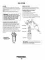
FUELSVSTEM
GASOLINE
ENGINE FUEL FILTER
Use unleaded 89 octane or higher gasoline. When fueling,
follow U.S. Coast Guard regulations, close off all hatches and
companionways to prevent fumes from entering the boat, and
ventilate after fueling.
NOTE: The generator compartment should have a gasoline
fume detector/alarm properly installed and working.
Periodically check the fuel connections and the bowl for
leakage. Replace the fliter element after the first 50 hours
then follow the MAINTENANCE SCHEDULE.
Changinglcleaning the filter element.
1.
2.
3.
4.
5.
6.
AWARNING: Shut off the fuel valve at the tank
when servicing the fuel system. Take care in catching
any fuel that may spill. DO NOT allow any smoking,
open Hames or other sources of fire near the fuel
system when servicing. Ensure proper ventilation
exists when servicing the fuel system.
Shut the fuel supply off.
Unscrew the filter bowl from the housing.
Pull the fuel element down and off.
Inspect the sealing O-ring and replace if necessary.
Install a new fliter element and reassemble the bowl.
Screw the bowl on tightly by hand. Open the fuel supply
and run the engine to inspect for leaks.
GASOLlNEIWATER SEPARATOR AND FILTER
A primary fuel filter of the water separating type must be
installed between the fuel tank and the engine to remove
water and other contaminant's from the fuel before they can
be carried to the fuel system on the engine.
Most installers include a type of filter/water separator with
the generator installation package as they are well aware of
the problems that contaminant's in the fuel can cause.
These gasoline fliters must have metal bowls (not "seethrough") to meet U.S. Coast Guard requirements. The metal
bowls have drain valves to use when checking for water and
impurities.
FILTER HOUSING ~
FILTER ELEMENT--
FUEL IN
GASOLlNEjWATER
SEPERATDR & FILTER
OWNER INSTALLED
A WARNING:
Fuel is present in the hDusing and lines.
Use extreme care to prevent spillage.
Engines & Generators
16
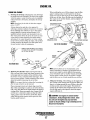
ENGINE OIL
When installing the new oil filter element, wipe the filter
gasket's sealing surface on the bracket free of oil and
apply a thin coat of clean engine oil to the rubber gasket
on the new oil filter. Screw the filter onto the threaded oil
filter nipple on the oil filter bracket, and then tighten the
filter firmly by hand.
ENGINE OIL CHANGE
1. Draining the Oil Sump. Discharge the used oil through
the sump drain hose (attached to the front of the engine)
while the engine is warm. Drain the used oil completely,
replace the hose in its bracket, and replace the end cap
securely.
NOTE: Thread size for the lube oil drain Iwse capped
end is 1/4 NPT.
Always observe the used oil as it is removed. A
yellow/gray emulsion indicates the presence of water in
the oil. Although this condition is rare, it does require
prompt attention to prevent serious damage. Call a
qualified mechanic should water be present in the oiL
Raw water present in the oil can be the result of a fault
in the exhaust system attached to the engine andlor a
siphoning of raw water through the raw water cooling
circuit into the exhaust, filling the engine. This problem
is often caused by the absence of an anti-siphon valve,
its poor location or lack of maintenance.
(( .)~.........--:;r---·
OIL FILTER ASSEMBLY
FILTER
GASKET APPLY CLEAN OIL
WHEN ASSEMBLING
NEW FILTER
~
REMOVE USING AN 8MM (11116"0 SOCKET
TO DRAIN THE OIL OR PUMP THE WARMED
OIL UP THRU THE HOSE
.,
DI~~TICK~
TU~OllPAN
OIL DRAIN HOSE
-~
2. Replacing the Oil Filter. When removing the used oil
filter, you may find it helpful and cleaner to punch a hole
in the upper and lower portion of the old filter to drain
the oil from it into a container before removing it. This
helps to lessen spillage. A small automotive filter wrench
should be helpful in removing the old oil filter.
NOTE: Do nol punch this hole without first loosening the
filter to make certain it can be removed.
Place some paper towels and a plastic bag around the
filter when unscrewing it to catch any oil left in the filter.
(Oil or any other fluid on the engine reduces the engine's
cooling ability. Keep your engine clean.) Inspect the old
oil filter as it is removed to make sure that the rubber
sealing gasket comes off with the old oil filter. If this
rubber sealing gasket remains sealed against the filter
bracket, gently remove it.
NOTE: Generic filters are not recommended, as the
material standards or diameters of important items on
generic parts might be entirely different from genuine
parts. Immediately after an oil filter change and oil fill,
run the engine to make sure the oil pressure is nonnal
and that there are no oil leaks around the new oil filter.
3. Filling the Oil Sump. After refilling, run the engine for a
few moments while checking the oil pressure. Make sure
there is no leakage around the new oil filter or from the
oil drain system. and stop the engine. Then check the
quantity of oil with the lube oil dipstick. Fill to, but not
over the high mark on the dipstick, should the engine
require additional oil.
A CAUTION: Used engine oil contains harmful
contaminates. Avoid prolonged skin contact. Clean
skin and nails thoroughly using soap and water.
Launder or discard clothing or rags containing used oil.
Discard used oil properly.
Engines & Generators
17
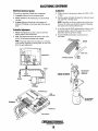
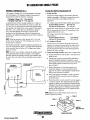
THE BATTERY CHARGING CIRCUIT
The DC Circuit on the BCGB functions to start, operate and
stop the generator's engine. The circuit is best understood by
reviewing the DC Wiring Diagram and Wiring Schematic.
The engine's DC wiring is designed with three simple basic
, circuits: start, run and stop.
Battery Maintenance
Review the manufacturer's recommendations and then establish a systematic maintenance schedule for your engine's
starting batteries and house batteries.
The engine has a 12 volt DC electrical control circuit that is
shown on the WIring Diagrams. Refer to these diagrams
when troubleshooting or when serviQing the DC electdcaI
system or the engine.
• Monitor your voltmeter for proper charging during engine
operation.
BATTERIES
• Use only distilled water to bring electrolytes to a proper
level.
A CAUTION: To avoid damage to the battery chargIng clrcut, never shut off the engine battery switch
while the engine is running. Shut off the engine battery
switch, however, to avoid electrical shorts when working on the englne~ electrical circuit.
• Check the electrolyte level and specific gravity with a
hydrometer.
• Make certain that battery cable connections are clean and
tight to the battery posts (and to your engine).
• Keep your batteries clean and free of corrosion.
A WARNING: Sulfuric acid in lead batteries can
cause severe burns on skin and damage clothing. Wear
protective gear.
Specifications
The recommended capacity of the "dedicated" starting battery
used for the engine's 12VDC circuit is 600-800 C.C.A.
BATTERY CHARGER
The generator supplies a continuous 17 amp charge from
its battery charger to the starting battery. To test the battery
charger, put a multimeter between the positive (+) and
negative H leads to the battery. It should indicate l3.0V to
i3AV with the engine running. If only the battery voltage
is indicated, check that the battery charger terminal
connections are tight With the unit runiling, test between
the (+) and (-) terminals for 13.0V to 13AV. If no charge
is indicated, replace the charger.
RED TO
CIRCUIT BREAKER
GREEN H
BRIDGE RECTIFIER
GENERATOR CONTROL PANEL
TO GROUND
r J
I
I
- - - - - - - - -- - - -- - -- -- - -- -- - - - - - - -- - - - - - - -- - -- -- - - - - ,
IDC
I
30A
' AC
iCHARGE
I
At
I
-J>I- -
I.e.
INTEGRAL
I
CONTROLLER
I
i
I
:
I
Hz,
lI ___________________________
....J1
10., '
DEVOLTAGE OUTPUT";:\;'
ADJUSTMENT POT :i;';:~)f,
. . "~'.'I'
.
".:I".l.·n~
1'\C':'tF'<I
"~
C.WTO INCREAS.~ . J'i'/;)""';~J
C.C.W TO DECREASE L~,i~'S
TESTING THE
BATTERY CHARGER
Engines & Generators
18
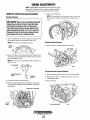
ELECTRONIC GOVERNOR
Electronic Governor System
Calibration
The system is composed of three basic components:
1. With no power to the governor, adjust the GAIN to 9:00
o'clock.
2. Start the engine and adjust the speed by turning lhe speed
pot clockwise to desired speed.
1. Controller. Mounted in the instrument panel.
Z. Sensor. Installed on the bellhousing over the flywheel
ring gear.
3. Actuator. Mounted at the front of the engine and
attached with linkage to the throttle arm of the injection
pump.
NOTE: Controllers are factory adjusted to minimum rpm.
However. for safety, one should be capable of disabling
.the engine if an overspeed should exist.
3. At no-load. turn the GAIN potentiometer clockwise until
the engine begins to hunt. if the engine does not hunt,
physically upset the governor linkage.
4. Turn the GAIN potentiometer counterclockwise
until stable.
Controller Adjustment
1. Speed. This adjustment is used to raise or lower the
engine's speed to the desired hertz.
2. Gain. This adjustment affects the reaction time of the
actuator to the generator/engine load changes.
NOTE: A high gain adjustment can induce an oscillating
of the actuator producing a hunting mode. In such cases,
lessen the gain adjustment.
CONTROLLER
FLYWHEEL HOUSING
LINEAR ACTUATOR
KEEP ACTUATOR
LINKAGE WELL
LUBRICATED
SENSOR
LINEAR
ACTUATOR
TO ELECTRONIC
CONTROLLER
Engines & Generators
19
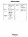
TROUBLESHOOTING THE ELECTRONIC GOVERNOR
PROBLEM
CDRRECnDN
TEST/CHECK
1. Check DC voltage between terminal
#12 and +connection on hourmeter
when ON switch is depressed.
1. Charge starting battery. Start unit, troubleshoot
battery, charge circuit.
2. Check the AC signal from the MPU
while cranking, voltage should be
1.5 • 2.5 VAC.
2. Check the MPU resistance value and positioning.
Adjust and replace as needed.
3. Check the actuator.
4. Check the controller.
3. Check the resistance value. Apply 12VOC across leds.
Should fully retract. Replace as needed.
4. Manually control unit. Start and check DC voltage
between #9 and #8, between '11 and 110.
Replace controller or OS board as needed.
Unit starts, runs at idle.
1. Incorrect speed adjustments ..
1. Check and adjust speed adjustment.
NOTE: Less than one volt DC
found between terminals 19 and
18 and high DC voltage-10 volts
or higher between terminals 111
and 110 indicated a faulty controller.
2. Faulty governor controller..
2. Check DC voltages from controller to OIS board
and OIS board to actuator.
Actuator hunts during operation.
NOTE: Check carburetor
adjustments before proceeding.
1. Improper controller adjustment.
1. Lessen GAIN adjustment.
2. Linkage or rod end bearings are
sticking or binding.
2. lubricate and replace as needed.
3. Inadequate DC supply voltage.
3. Manually stabilize the unit. Check the DC voltage
to the controller. Correct as needed.
4. Check the MPU signal. Adjust pOSitioning
as needed.
Unit starts, then overspeeds
and shuts down.
NOTE: When troubleshooting,
manually operate the throttle to
prevent an overspeed or disconnect
the throttle from the actuator and
operate manually.
4. MPU positioned marginally
too far away from the flywheel
teeth, giving an erratic AC input
signal to the controller.
Engines & Generators
20
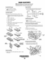
CARBURETOR ADJUSTMENTS
CARBURETOR
The carburetor is a single barrel, side-draft type with a
cleanable metal screen air intake filter/spark arrester.
ELECTRIC
The choke is operated by a 12 VDC solenoid. This choke
solenoid is activated when the ON switch is depressed and
stays activated so long as the ON switch is held depressed.
Once the ON switch is released the choke solenoid deactivates.
Air Screen/Flame Arrester
The air screen can easily be removed. Clean after the first 50
hours of operation, every 100 hours from then on. Clean the
air screen in a water soluble cleaner such as GUNK.
Drip Tray
Do not allow fuel to build up in the drip tray. Use the allen
//
screw drain to remove any fuel build up.
AIR SCREEN
SIDE DRAFT CARBURETOR
SPARK ARRESTER
SILENCER
FUEL SHUT OFF
SOLENOID
DRIPTRAV
CARBURETOR CHECKS FOR PROPER OPERATION
SPEED "''''''Tn,,,,./
ACTUATOR
1.
The idle mixture screw adjustment. Remove the plastic limiter. Turn the mixture
screw in till it seats. Then back it out 3 yz turns. Once running adjust the screw
no more than yz turn in or out to further stabilize engine operation.
2.
Verify that the choke mechanism flutters when the engine is cranking on a start.
The choke return spring should rest against the actuator mounting bracket.
3.
The throttle linkage's eye bolts need to be 25/8" apart (center to center). This
should place the throttle full open when the unit is shut down.
4.
Throttle actuator should move freely. Lubricate with Teflon or Gmphite lubricant "only".
5.
Carburetor inlet screen must be clean for good air flow into the engine.
Engines & Generators
21
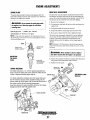
ENGINE ADJUSTMENTS
NOTE: WESTERBEKE recommends that the following engine
adjustments be performed by a competent engine mechanic.
The information below is provided to assist the mechanic.
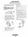
TIMING BELT INSPECTION AND REPLACEMENT
5. Remove the timing bell.
NOTE: lfthe timing belt is to be reused, draw an arrow on
the belt back to indicate the direction of rotation (clock·
wise).
Timing Belt Removal
A CAUTION: Water or oil on the timing belt severely
reduces the service lite of the belt. Keep the timing
belt sprocket and tensioner free of oil and grease.
These pans should never be cleaned. Replace if seriously contaminated with dirt or oil. If oil is evident on
these pans, check the front case~ oil pump oil seals,
and camshaft oil seals for a possible oi/leak.
1. Turn the crankshaft clockwise to align·the timing mark on
the camshaft sprocket and timing belt rear cover.
Camshaft Sprocket Removal
NOTE: always turn the crankshaft clockwise.
1. Remove the bolt without tuming the camshaft.
TIMING
MARK
2. Remove the plug on the left surface of the cylinder block
and insert a rod with a diameter of 8mm (O.3fin.) to lock
the counterbalance shaft.
NOTE: Be sure to use an inserting rod with a diameter of
8m111 (0.31 in.).
2.6 IN (65MM) ----1'......--~1O-i
ROD
Oil Pump Sprocket Flange Nut Removal.
1. Remove the plug from the left side of the cylinder block.
2. Insert an 8 mm (0.31 in.) diameter round bar to lock the
CYLINDER
BLOCK
counterbalance shaft.
3. Loosen the timing belt tensioner nut.
3. Remove the nut.
4. Move the timing belt tensioner toward the water pump,
and temporarily tighten the nut to hold the tensioner in
that position.
TIMING BElT TENSIONER
Engines & Generators
22
ENGINE ADJUSTMENTS
NOTE: WESTERBEKE recommends that the following engine
adjustments be peiformed by a competent engine mechanic.
The information below is provided to assist the mechanic.
Crankshaft Bolt Removal
Flange Installation
i.
1. Mount the flange so that its side shown by the heavy
anow in the illustTation faces toward the sprocket.
Lock the crankshaft in position.
NOTE: Do not turn the crankshaft.
FLANGE
2. Remove the crankshaft bolt.
rfWASHER
Timing Belt Inspection
-~--=W
Replace the belt if any of the following conditions exist:
I. Hardening of back rubber-back side is glossy, without
resilience, and leaves no indent when pressed with fingernail.
2. Cracks on rubber back.
Crankshaft Bolt Installation
3. Cracks or peeling of canvas.
1. Lock the crankShaft.
4. Cracks on tooth bottom.
NOTE: Do not turn the crankshaft.
5. Cracks on belt.
2. Tighten the crankshaft bolt to the specified torque.
6. AbnOlmal wear of belt sides. The sides are normal if
they are sharp as if cut by a knife.
Oil Pump Sprocket Flange Nut Installation
7. Abnormal wear on teeth.
1. Insert a round bar into the plug hole in the left side of the
8. Tooth missing and canvas fiber exposed.
cylinder block to keep the counterbalance shaft fTom turning.
2. Install the oil pump sprocket.
3. Tighten the nut to the specified torque.
CRACKS OR
PEELING
3.
lOll PUMP
SPROCKET
ABNORMAL WEAR
(FLUFFY STRANO)
Camshaft Sprocket Bolt Installation
5.
6.
1. Tighten the bolt to the specified torque.
TOOTH MISSING
AND CANVAS
FIBER EXPOSED
RUBBER
EXPOSEO-,----ho
,
7.
Bearing Cap Bolt Torque 36 40 fUbs (50 -55 Nm)
8.
Tensioner Inspection
1. Replace the tensioner if the pulley binds, rattles or is noisy
when turned.
BOLT
Engines & Generators
23
ENGINE ADJUSTMENTS
NOTE: WESTERBEKE recommends that the following engine
adjustments be peiformed by a competent engine mechanic.
The information below is provided to assist the mechanic.
At this time, check that the moveable range of teeth on
the oil pump sprocket is according to specifications.
Standard value: 4 to 5 teeth in forward direction.
1 to 2 teeth in reverse direction.
Tensioner Spring/Timing Tensioner Installation
1. Install the tensioner spring and timing belt tensioner.
2. Hook the tensioner spring onto the bend of the timing belt
tensioner bracket and the stopper pin on the cylinder
block.
3. Move the timing belt tensioner as close as possible to the
water pump; temporarily tighten the tensioner nut.
TIMING BELT
TENSIONER
OIL PUMP
SPROCKET
REVERSE
4. If the movable range of the oil pump sprocket exceeds
the specified range, correct as follows:
a. Pull out the round bar from the plug hole in the left
side of the cylinder block.
b. Turn the oil pump sprocket one turn at a time until
the round bar can again be inserted.
Timing Belt Insiallation
c. Check that the movable range of the oil pump
sprocket is in the specified value.
1. Align the trlangular marking on ,the camshaft sprocket
with a marking on the timing belt rear cover.
S. Set the timing belt over the crankshaft sprocket and
then over the oil pump sprocket and camshaft sprocket,
in that order.
2. Align the notch in the crankshaft sprocket flange with
the marking on the front case.
NOTE: Ensure that the tension side of the timing belt is
not slack. Keep the round bar inserted until the timing
belt has been placed. After this step, be sure to remove
the round bar.
3. Align the triangular marking on the oil pump sprocket
with the marking on the front case, and then insert a 65
mm (2.56 in.) or longer, 8 mm (0.31 in.) diameter
round bar into the plug hole in the left side of the
cylinder block.
6. Apply counterclockwise force to the camshaft sprocket
to make the belt taut on the tension side, and make
sure that ail timing marks are lined up.
MARKING ON
TIMING BELT
REAR COVER
TRIANGULAR'
MARKING ON
CAMSHAFT
CAMSHAFT
SPROCKET
SPROCKET
TENSION SIDE
TIMING BELT
TENSIONER,
7. Loosen the temperorarily tightened tensioner nut on
the water pump side 1 or 2 turns, and tension the belt
making use of spring force.
NOTCH IN
CRANKSHAFT
SPROCKET
flANGE
MARKING
ON FRONT
CASE
-~----'WESTERBEKE
Engines & Generators
24
ENGINE ADJUSTMENTS
NOTE: WESTERBEKE recommends that the following engine
adjustments be peiformed by a competent engine mechanic.
The information below is provided to assist the mechanic.
8. Turn the crankshaft clockwise by nine camshaft sprocket
teeth (817) to align the timing mark on the camshaft
sprocket with the tensioner set mark on the timing belt
rear cover.
A
CAUTION: This operation is performed to give a
proper tension to the timing belt, so do not tum the
crankshaft counterclockwise and push the belt to
check the tension.
ENGINE COMPRESSION TEST
1. To check the engine's compression pressure, warm up the
engine then shut it down.
2. Remove the three spark plug caps and remove the three
spark plugs.
3. InstaIJ a compression adapter and gauge in the spark plug
hole.
4. Close off the raw water intake seacock.
5. Crank the engine with the start motor and unplug the
ignition coil and allow the compression gauge to reach a
maximum reading and record.
TENSIONER
"';::::""'"h.,_-,SET MARK
6. Measure the compression pressure for all the cylinders.
Ensure that compression pressure differential for each
cylinder is within the specified unit.
Compression pressure should not differ by more Ihan 14 psi (100 Kpa).
9. Make sure that the timing belt teeth are engaged with
the camshaft sprocket teeth along the portion of the
sprocket shown by the curved arrow in the illustration
below. Then tighten the tensioner nut.
10. Pull the timing belt in the center of the tension side
toward the sealing gasket line for the belt cover, as
illustrated. Make sure that the clearance between the
back of the belt and the sealing line is the standard
value.
7. If a cylinder's compression or pressure differential is
below the limit, add a small amount of engine oil through
the spark plug hole and repeat steps 4 and 5.
(a) If additional of oil causes an increase of pressure, the
piston ling and/or cylinder wall may be worn or damaged.
(b) If additional oil does not increase compression pressure suspect poor valve contact, valve seizure, or valve
wear.
8. Reinstall three plugs and ignition wires.
9. Open the raw water thru seacock.
Standard Value: 12mm (0.47in.)
SEALING
GASKET LINE
COMPRESSION
GAUGE
(TYPICAL)
ADAPTER
~~j
11. Pull out a rod from the plug hole on the left surface of
the cylinder block and apply the specified sealant.
Then tighten the plug to the specified torque.
~~I
Specified sealant value; 3M AID Part No. 8660 or
equivalent
Tightening torque: 15-22 Nm (11-16 ft.lbs.)
Engines & Generators
25
ENGINE ADJUSTMENTS
NOTE: WESTERBEKE recommends that the following engine
adjustments be performed by a competent engine mechanic.
The information below is provided to assist the mechanic.
VALVE CLEARANCE ADJUSTMENT
IGNITION TIMING
NOTE: Retorque the cylinder head bolts before adjusting the
engine's valves (see TORQUING THE CYLINDER HEAD
BOLTS).
1. Attach a timing light to the #1 spark plug and mark the
front timing pointer to indicate 15°. Locate the timing
mark on the crankshaft pulley and mark it with white
chalk or a crayon.
1. Remove the rocker cover and gasket.
2. Rotate the crankshaft in the normal direction of rotation,
placing the No.1 piston at the top of its compression
stroke with the exhaust and intake valves completely
closed. Adjust the intake and exhaust valves for No.1
cylinder, the exhaust valve for No.2 cylinder, and the
intake valve for No.3 cylinder (see chart).
3. Rotate the crankshaft 1800 in its nOlmal direction of
rotation. Locate the piston in No.1 cylinder at the top of
its exhaust stroke. Adjust the intake valve for No.2
cylinder and the exhaust valve for No.3 cylinder (see
chart).
2. Start the engine and warm it up to its normal operating
temperature. Make sure the generator is operating without
a load on it.
3. Using the timing light, align the timing mark in the front
crankshaft puI1ey so it is just slightly before the first timing pointer. Do this by loosening and slowly rotating the
distributor body. Use the following timing specifications:
Timing Specifications: 15" ± .50 BTDe at 1800 rpm
(no load on generator)
, IGNITION TIMING
CYLINDER #
CRANK ANGLE
1
When No. 1 piston is set at top of
compression stroke
IN
EX
When No. 1 piston is positioned
at top of exhaust stroke
IN
EX
2
3
•• • •
•
•
I
4•. Replace the rocker cover along with a new rocker cover
gasket..
TORQUING THE CYLINDER HEAD BOLTS
Rocker cover torque: 2.9-5.1 (b-n (4 • 7 Nm)
After the initial break-in peliod (approximately 50 hours), the
cylinder head bolts should be re-torqued.
Tighten the cylind~r head bolts according to the sequence
shown. Make sure the engine is cold when this is done, and
loosen one head bolt one-half turn and then tighten it
between 43 51lb-ft (60 70 Nm). Then proceed to the next
head bolt in the sequence. Tighten the RS (rocker cover stud)
securely.
6
VALVE
CLEARANCE
Valve Clearance:
Inlake
Exhaust
O.20mm (.008 inches)
0.30mm (.0:12 inches)
FRONTO~
ENGINE ~
Engines & Generators
26
4
2
7
ENGINE ADJUSTMENTS
SPARK PLUGS
DRIVE BELT ADJUSTMENT
The spark plugs should be cleaned and regapped after the
first 50 hour break-in period, then inspected every 250 hours
thereafter and replaced as needed.
The drive belt must be properly tensioned. Excessive drive
belt tension can cause rapid wear of the belt and reduce the
service life of the fresh water pumps bearing. A slack belt or
the presence of oil on the belt can cause belt slipping.
1. Remove the belt guard.
A WARNING: Do not remove the spark plugs while
2. To release the belt, back off the pivot bolt and loosen the
bracket bolt.
the engine is hot. Allow the engine to cool before
removing them.
3. Swing the bracket to loosen for removal.
4. Inspect the belt for frayed edges and excessive wear.
Spark plug gap: 0.031 - ± 0.0002 in. (0.8 - 0.05 mm).
S. Re-install or replace the belt and re-tighten the bolts.
Spark plug torque: 10 -15Ib·ft (1.5 - 2.31 kg.m).
The drive belts are properly adjusted if it can be deflected
no less than 3/8 inch (lOmm) and no more than 112 inch
(12mm) as the belt is depressed with the thumb at the
midpoint between the two pulleys on the longest span of
the belt.
NOTE: Loctite Anti-Seize applied to the threaded portion of
the spark plugs will retard corrosion, making future removal
of the spark plugs easiel:
GAP
NOTE: Maintain a 22 Ib pressure to the belts outer face for
proper belt operation. Spare belts should always be carried
on board.
/' INSPECT FOR
DAMAGE
INSPECT FOR
WEAR & CARBON
A WARNING: Never attempt to check
01 adjust a
drive belt's tension while the engine is in operation.
INSPECTING
THE SPARK
PLUGS
CHOK~
6. Operate the generator for about 5 minutes, then shut down
the generator and recheck the belt(s) tension.
--CHECK FOR
DETERIORATION
AND DAMAGE
7. Replace the belt guard.
SOLENOID
The choke solenoid is a 12 volt DC operated unit that functions to close the choke plate in the carburetor when the ON
switch is depressed during engine start-up.
RAW WATER PUMP
BRACKET
The choke solenoid de-energises once the engine starts and
the ON switch is released. Some unstable running may be
present when the engine starts cold, but should smooth out as
the engine reaches normal operating temperature.
Keep this solenoid dry and periodically lubricate the linkage,
plunger and choke shaft with graphite lube.
_ _ CHOKE SOLENOID
"it
CARBURETOR
Engines & Generators
27
GENERATOR INFORMATION
USE OF ELECTRIC MOTORS
GENERATOR FREQUENCY ADJUSTMENT
The power required to start an electric motor is considerably more
than is required to keep it running after it is started. Some motors
require much more current to start them than others. Split-phase
(AC) motors require more current to start, under similar
circumstances, than other types. They are commonly used on
easy-starting loads, such as washing machines, or where loads are
applied after the motor is started, such as small power tools.
Because they require 5 to 7 times as much current to start as to
run, their use should be avoided, whenever possible, if the electric
motor is to be driven by a small generator. Capacitor and
repulsion-induction motors require from 2 to 4 times as much
current to start as to run. The current required to start any motor
varies with the load connected to it An electric motor connected
to an air compressor, for example, will require more current than a
motor to which no load is connected.
In general, the current required to start 115-Volt motors connected
to medium starting loads will be approximately as follows:
Frequency is a direct result of engine/generator speed, as
indicated by the following:
• When the generator is run at 1800 RPM, the AC voltage
output frequency is 60 Hertz.
• When the generator is run at 1500 RPM, the AC voltage
output frequency is 50 Hertz.
MOTOR SIZE
(HP)
AMPS FOR
RUNNING
(AMPERES)
AMPS FOR
STARTING
(AMPERES)
1/6
3.2
6.4 to 22.4*
1/4
4.6
1/3
5.2
9.2 to 32.2*
In d
1/2
7.2
14.4 to 29.2*
3/4
10.2
20.4 to 40.8"
1
13
26 to 52
Therefore, to change the generator's frequeney, the generator's
drive engine's speed must be changed along with a reconfiguring
of the AC output connections at the generator.
GENERATOR MAINTENANCE
•
Maintaining reasonable cleanliness is important.
Connections of terminal boards and rectifiers may become
corroded, and insulation surfaces may start conducting if
salts, dust, engine exhaust, carbon, etc. are allowed to build
up. Clogged ventilation openings may canse excessive
heating and reduce life of windings.
•
For unusually severe conditions, thin rust-inhibiting
petroleum based coatings should be sprayed or brushed over
all surfaces to reduce rusting and corrosion.
•
In addition to periodic cleaning, the generator should be
inspected for tightness of all connections, evidence of
overheated terminals and loose or damaged wires.
•
The drive discs on single bearing generator's should be
checked periodically if possible for tightness of screws and
for any evidence of incipient cracking failure. Discs should
not be allowed to become rusty because rust may accelerate
cracking. The bolts which fasten the drive disc to the
generator shaft must be hardened steel SAE grade 8,
identified by 6 radial marks, one at each of the 6 comers of
the head.
•
The rear armature bearing is lubricated and sealed; no
maintenance is required. However, if the bearing becomes
noisy or rough-sounding, have it replaced.
•
Examine the bearing at periodic intervals. No side movement
of the shaft should be detected when force is applied. If side
motion is detectable, inspect the bearing and shaft for wear.
Repair must be made quickly or major components will rub
and cause major damage to the generator.
*NOTE: In the above table the maximum Ampsfor Starting is
more for some small motors than for larger ones. The reason for
this is that the hardest starting types (split-phase) are not made in
larger sizes.
Because the heavy surge of current needed. for starting motors is
required for only an instant, the generator will not be damaged if it
can bring the motor up to speed in a few seconds. If difficulty is
experienced in starting motors, tum off all other electrical loads
and, if possible, reduce the load on the electric motor.
REQUIRED OPERATING SPEED
Run the generator first with no load applied, then at half the generator's capacity, and finally loaded to its full capacity as indicated
on the generator's data plate. The output voltage should be
cheeked periodically to ensure proper operation of the generating
plant and the appliances it supplies. If an AC voltmeter or ampmeter is not installed to monitor voltage and load, check it with a
portable meter and amprobe.
Carbon Monoxide Detector---------,
WESTERBEKE recommends mounting a carbon monoxide
detector in the vessel's living quarters. Carbon monoxide,
even in smaU amounts, is deadly.
TIle presence of carbon monoxide indicates an exhaust leak
from the engine or generator or from the exhaust elbow!
exhaust hose, or that fumes from a nearby vessel are
entering your boat.
If carbon monoxide is present, ventilate the area with clean
air and correct the problem immediately!
NOTE: When the vessel in which the generator is installed contains AC equipment of J20 volts only, it is recommended that the
generator sAC temlinal block be configured to provide one J20
volt AC hot legfor the vessel's distribution panel. This will ensure
good motor starting response from the generator.
Engines & Generators
28
AC TERMINAL CONNECTIONS
BCGA & C
120Vl60Hz
#31
230Vl50HZ
240V/60Hz
#11
#11
#21
#42<
#41
#41
CIRCUIT
BREAKER
~.
ISOLATED
POST
(NEUTRAL)
L1
N
L2.
#31
CIRCUIT
BREAKER
ISOLATED
POST
(NEUTRAL)
L1
#22 #42
#11
#21
#31
CIRCUIT
BREAKER
115V150HZ
-
ISOLATED
POST
I
N
L1
N
ISOLATED
POST
N
L1
BCGA & C GENERATOR WINDINGS SCHEMATIC
El1~ ~1
•
L..*:JE22
-----I
,.----------T11
t-------- T31
EWl
'"-------T41
L..--------T42
'-----------T21
L..-------------T22
~-Vl
'------V2
EW1 EXCITER WINDING 1
EW2 - EXCITER WINDING 2
BCW - BATTERY CHARGER WINDING
RW - ROTOR WINDING
60Hz OPERATION: CONNECT CAPACITORS TO E3'·E41/E1,·E21
50Hz OPERATION: CONNECT CAPACITORS TO E31-E421E1'-E22
W1 - STATOR WINDING 1
W2 - STATOR WINDING 2
C,
CAPACITOR
D1/D2-DlODES
Engines & Generators
29
BeG & 0 AC TERMINAL CONNECTIONS
120V/60Hz
1
230Vl50HZ
240V/60Hz
+
1
1
5
4
CIRCUIT
BREAKER
115V1'50HZ
6
2
CIRCUIT
BREAKER
CIRCUIT
BREAKER
ISOLATED
POST
L1
l1
ISOLATED
POST
L2.
N
BeG & 0 GENERATOR WINDINGS SCHEMATIC
~ ;:[*1:·
r ------- - - - I
I
I
I
I
ROTOR WINDINP
I
I
I
I
I
I
I
.
I
I
!
I
I
I
I
I
I
I
I
L- -:C~~R
~----o2
,
I
I
STATOR WINDING
I
I
STATOR WINDING
I
j
I
w,:Ji.-rn
--,---06
6t,'F
g 7
CAPACITOR.
Engines & Generators
29A
Ef
BATIERY CHARGING CIRCUIT
50 Hz
I
I
ROTOR WINDING
~.
~~
-
l1
SHORE POWER TRANSFER SWITCH
230 VOLT/50 HERTZGenerator
TWO WIRE CONFIGURATION
120 VOLT/GO HERTZ TWO WIRE CONFIGURATION
Generator
~
NOTE: Diagram shows connections for a twowire, 120 Voit system from the generator,
with three-wire. 120-Voll boat system.
~
w
Ll
:N
-
Ship·to· Shore Switch (3 Pole)
Q
.J
III
/...-- .......,
'---t--t----f-@9\Neutral
iiif?!
~
~
Z
L1
./Je/+,-+--(W-H-T-)-"N
--",~~ro~un~d~~_ _~ ii'
w ·
L2
Ships Load
NOTE:
No 240-Voll
Equipment
PN 32008
(40Amps!Pole)
PN 32009
(60Amps! Pole)
PN 32010
(125 Amps! Pole)
PN 32133
(200 Amps! Pole)
GENERATOR
GROUND
zw
w
a:
"
PN 32133
w
I'
:<:
::i
o
!::
;;:
GENERATOR/SHORE
SWITCH
r:D:
....... -
.......
1
~L1
!
'\
/
!
2 I
,--~'---~~3
"
'-_.-' /
SHIP'S
LOAD
(GRN)
/ ......
~
L---~~:5
(NEUTRAL)!
,....-'-----'-'rf7
Shore Power
If the installer connects shore power to the vessel's AC
circuit, this must be done by means of the Shore Power
Transfer Switch.. Set the transfer switch shown in the
diagrams to the OFF position. This switch prevents
simultaneous connection of shore power to generator output.
-
........
,
~N
6 I
!
'- ' - _ / /
-=
~
SHORE
GROUND
_ SHIP'S
- GROUND
SHORE POWER
230V 50HZ
A
CAUTION: Damage to the generator can result if
utility shore power and generator output are connected
at the same time. This type of generator damage is not
covered under the warranty; it is the installer's responsibility to make sure all AC connections are correct.
Switching Shore Power to Generator Power
A
CAUTION: Heavy motor leads should be shut off
before switching shore power to generator power or
vice-versa because voltage surges induced by switching
with heavy AC loads on the vessel being operated may
cause damage to the exciter circuit components in the
generator.
Engines & Generators
30
BC GENERATOR SINGLE PHASE
INTEGRAL CONTROLLER (I.C.)
Testing the Battery Charging Circuit
The Integral Controller (I.C.) is an encapsulated, solid-state
unit that supplies a DC charging voltage to the generator's
starting battery while the generator is opening.
1. Bridge Rectifier
Charging Voltage: 13.1 • 13.4 volts DC
Charging Amperage: 0 • 17.0 amps DC
A separate group of stator windings supplies AC voltage to a
bridge rectifier which converts the AC current to supply the
I.e. unit. The I.e. unit senses the needs of the starting battery
and supplies a DC charge when one is needed. If you susp~ct
that the I.C. unit is faulty (that is, if the battery's charge is
low), check the charging circuit and it's components as
described in the following steps. Check all connections for
cleanliness and tightness including the ground before replacing
the I.C. unit.
NOTE: When the generator is first started, the L C. unit will
produce a low charging rate. This charging rate will rise as
the generator is operated.
NOTE: New four wire controllers eliminate the ballast resistor
circuit since the ballast resistor's junction is now handled
internally. Whenever replacing an early stylr controller with
the newer four wire model, remove the ballast resistor and its
wiring.
VOLTAGE OUTPUT
AOJUSTME.NT
VOLT
~
-
BRIDGE
RECTIFIER'
GND
GREEN
RED
~
Lift the two AC wire leads off the bridge rectifier and
measure, the resistance between these two leads with an
ohmmeter. It should measure 0.10 ohm. No continuity
should exist between these two leads and the ground or
the main AC stator windings.
3. Testing the Bridge Rectifier (meter used - Simpson 260)
a. Set your ohmmeter's scale on RXI (+ DC) and set the
needle to zero.
b. Connect the (+) positive lead from the ohmmeter to
point #4. Taking the ohmmeter's negative H lead,
momentarily touch points #1, #2, #3, and #5. The ohmmeter should register no deflection for any of the
points touched.
c. Remove the positive (+) lead from point #4 and
connect the negative (-) lead; momentarily touch
points #1, #2, and #3. The ohmmeter's needle should
deflect when each point is touched.
d. Leaving the negative ohmmeter (-) lead on point #4,
. touch point #5 with the positive lead. No deflection
should take place.
e. Place the positive (+) lead on point #1 and the negative
(-) lead on point #3. The ohmmeter again should not
register any deflection (no deflection indicated infinite
resistance). Reverse these connections and the ohmmeter should again register no deflection. If the rectifier
fails any of the previous tests (A-E), replace the rectifier because it is defective,
AC
o
Normal DC voltage running out of the rectifier (in volts
DC) is measured across the two DC connections of the
bridge rectifier; that is + and -.
DC voltage running from the bridge rectifier
(approximate):
No-load off the generator
17.0 volts DC
Full-load off the generator
18.5 volts DC
2. AC winding: O.lOohm
The Integral Controller is mounted inside the generator housing in the 12:00 position. There is a voltage output adjustment
on the controller that wi1I allow a DC voltage output adjustment of ± 2 volts.
+
Normal AC voltage running to the rectifier (while the
engine is operating at 1800 rpm) is measured across the
two AC connections on the bridge rectifier. (As
illustrated).
AC voltage running to the bridge rectifier (approximate):
No-load off the generator
16.0 volts AC
Full-load off the generator 17.5 volts AC
:z:
[;)
m
NOTE: Different types and/or brands of test meters may
produce opposite test results.
GROUND TO
GENERATOR CASE
POINT 1/1
POINT 14
POINT #5
MOUNTING HOLE
Engines & Generators
Revised August 2003
31
. BRIDGE- RECTIFIER
WIRING SCHEMATIC
#46876
+
12
vee
BATTERY DISCONNECT SWITCH
NOTE: An on-off switch
should be Installed in this
circuit to disconnect the
starter from the battery in
an emergency and when
leaving the boat. Twelve
volt engine starters
typically draw 200 to 300
amps when crankiflg. A
BATTERY !2VDC
BATTERY CHARGER
HOUR METER
'2
DI STi I SUTOR
switch with acontinuous
rating of 175 amps at 12
VDCwill normally serve
this function, but switch
must never be used to
"make" the starter circuit
rUEL PUMP
a
FUEl SOL.
~
'2, RUN RE LAY
}8 5______________--1
____-+_________8~'
r
CHOKE SOl.
K I-STA.RT RElAY
~~~oL-~~~,~~------_+----~------_+---------8ri6
I
I
I
}8i5 ______________--1
AUX. Oil PRESS. SWITC1-I
rrl
elK
..~f8J _ITl .
!!IIMUE COM!ECIl!R
SHORT I NG PLUG ~ JUMPER PINS 2 TO
5:
TROUBLL';;OOOTING - WHEN TROUBLESHOOTING
THE DC CIRCUIT: TO BY PASS THE OVERSPEED TO
DETERIME IF IT IS FAULTY. MOVE CONNECTION #3 TO
CONNECTION #5.
NOTE - DO NOT OPERATE TIlE UNIT WI11l THE OVERSPEED
BYPASSED.
Engines & Generators
32
Fffi-IIRE II SAW(; II GSDEG C 600V·AlPNU
IBSSII&·MII+16818D TYPE 81 UNlESS
SPECIFIED OTHERWISI.
l. ,AJUil1CG RElAYS Kl. K2 HAVE INfERNAL
DIODES ACROSS THEIR COilS. POUlilT" AS
INDICATED MUST BE MAlHTAINU TO AVOID
DAIIAGE TO THE RHAYS.
WIRING DIAGRAM
#46876
A.UX. OL PRESS
.,
SWITCH INICI
OL PRESS
AC GEN.
SWITCH WOl
""
~
o~ .
«
«
'"
'"
-
~
rus£
'"c
~
'"
+
116 V10fW
r
w
.
~
tl4 RED/VIO
'"
""
w
«
""
~
Ii
!:
112 YEL/RED
FIJSE 8A
t'2 RED
ON
SWITCH
tl& RED/WHT
'16 ORG
tl6 WHT
"116
START/STOP
SWITCH
elK
116 RED/VIO
;;
Engines & Generators
33
30A
REMOTE PANEL WIRING
SCHEMATIC
REMOTE PANEL #043912 WITH 1 FOOT HARNESS
START/STOP SW
#14 5LK
RED
#14 WHT/RED
#14
YELIRED
#14 WHT
#14 RED/VIO
VIEWED FROM
MATING END
EXTENSION HARNESS
15 Feet PN# 043914
30 Feet PN# 043860
Engines & Generators
34
ENGINE TROUBLESHOOTING
The following troubleshooting tables are based upon eertain
engine problem indicators and the most likely causes of the
problems.
NOTE: 171e engines control system (electrical system) is
protected by a 20 Ampere manual reset circuit breaker
located on the control panel.
When troubleshooting indicates an electrical problem, see the
ELECTRICAL SYSTEM WIRING DIAGRAM, as these
may reveal other possible causes of the problem which are
not listed below.
PROBABLE CAUSE
PROBLEM
Engine does not
crank.
Engine starts, runs
and then shuts
down.
Engine starts. runs
but does not come
up to speed.
PROBLEM
1. Voltage drop at starter solenoid
terminal.
2. Engine circuit breaker has tripped.
3. 8 amp fuse/holder is faulty.
4. Battery is low or dead.
5. Loose battery connections.
6. Faulty wire connection.
7. Faulty start switch.
8. Faulty start relay (Kl).
9. Faulty starter solenoid
10. Raw water filled cylinders.
1. Faulty shutdown switch,
(oil pressure, water or exhaust
temperature).
2. Faulty overspeed switch
(See note below).
3. Dirty fuel/water separator filter.
4. Mechanical check valve at the fuel
supply faulty (if installed).
5. Low oil level in sump.
6. Faulty fuel pump.
7. High engine water or
exhaust temperature.
Engine cranks but
fails to start.
Engine hunts.
Engine misfires.
Engine backfires.
PROBABLE CAUSE
1. Out of fuel.
2. Engine is flooded.
3. Faulty carburetor.
4. Faulty choke solenoid.
1. Controller gain adjustment needed.
2. Faulty fuel pump.
3. Mag pick-up sensor needs adjustment.
4. Low DC battery voltage.
5. Generator overload.
6. Valves need adjustment.
1. Poor quality fuel.
2. Incorrect timing.
3. Dirty flame arrester.
4. Cracked distributor cap.
5. Faulty ignition wires.
6. Spark plugs are worn.
7. High exhaust back-pressure.
S. Valve clearances are incorrect.
1,. Spark plug wires are connected wrong.
2. Incorrect timing.
3. Engine is flooded. See Engine is
flooded under Engine cranks but
fails to start.
1. Faulty mag-pickup sensor.
2. Electronic governor controller faulty,
3. Fuel pump.
4. Fuel supply to engine restricted.
5. Throttle linkage binding.
6. Actuator or electrical connections
faulty.
7. AC generator overload.lshort.
8. Air intake restricted.
9. Exhaust restricted.
4. Dirty flame arrester.
5. Cracked distributor cap.
6. High exhaust back-pressure.
Engine overheats,
1. Coolant loss. Pressure test
cooling system.
2. Faulty raw water pump impeller.
3. Belts are loose or broken.
4. Raw water pump worn.
5. Faulty thermostat.
NOTE: OVERSPEED SWITCH: TO BY-PASS THE OVERS PEED SWITCH WHEN TROUBLESHOOTING
MOVE CONNECTION #3 AND CONNECT IT ONTO AND WITH #5.
REFER TO WIRING DIAGRAM #46876.
Engines & Generators
35
ENGINE TROUBLESHOOTING
PROBLEM
Low oil pressure,
PROBABLE CAUSE
1.
2.
3.
4.
5.
6.
PROBLEM
Low oil level.
Wrong SAE type oil in the engine,
Faulty or wrong type oil filter,
Relief valve is stuck,
Faulty oil pump.
Faulty engine bearings.
Black exhaust smoke
discharge from the
engine.
1. Dirty flame arrester.
2. Faulty carburetor.
3. Idle mixture jet too rich.
4. Faulty choke/solenoid,
5. Valves are worn or incorrectly
adjusted.
7. Faulty oil filter,
High oil pressure.
PROBABLE CAUSE
6. Piston rings are worn or unseated,
1. Dirty oil or wrong SAE type oil in the
Poor performance
at generator speed,
engine.
2. Relief valve is stuck,
No DC charge to the
starting battery.
1. Faulty connections to
battery charging control.
30
amp fuse blown/faulty,
2.
3. Faulty battery charging control.
4. Faulty bridge rectifier,
5. Faulty generator charger
windings,
Blue exhaust smoke
1. Lube oil is diluted.
discharge from the
engine,
2. High lube oil level.
3. Crankcase breather hose is clogged,
4. Valves are worn or adjusted
1. Contaminates in carburetor.
2. Faulty fuel pump/contaminated.
3. Electronic governor controller needs
adjustment.
incorrectly,
5. Piston rings are worn
or unseated.
. Engines & Generators
36
LAY-UP & RECOMMISSIONING
Fuel System [Gasoline]
G~NERAL
Many owners rely on their boatyards to prepare their craft,
including engines and generators, for lay-up during the offseason or for long periods of inactivity. Others prefer to
accomplish lay-up preparation themselves.
Top off your fuel tanks with unleaded gasoline of 89 octane
of higher. A fuel conditioner such as STABIL gasoline
stabilizer should be added. Change the element in your
gasoline/water separator and clean the metal bowl.
Re-install and make certain there are no leaks. Clean
up any spilled fuel.
The procedures which follow will allow you to perform your
own lay-up and recommissioning, or you may use them as a
check list if others do the procedures.
These procedures should afford your engine protection
during a lay-up and also help familiarize you with the
maintenance needs of your engine.
If you have any questions regarding lay-up procedures, call
your local servicing dealer; he will be more than willing to
provide assistance.
Fuel System [Diesel]
Propeller Shaft Coupling [Propulsion Engine]
The transmission and propeller half couplings should always
be opened up and the bolts removed when the boat is hauled
out of the water or moved from land to water, and during
storage in the cradle. The flexibility of the boat often puts a
severe strain on the propeller shaft or coupling or both, while
the boat is taken out or put in the water. In some cases, the
shaft has actually been bent by these strains. This does not
apply to small boats that are hauled out of the water when
not in use, unless they have been dry for a considerable
period of time.
Fresh Water Cooling Circuit
A 50-50 solution of antifreeze and distilled water is
recommended for use in the coolant system at all times.
This solution may require a higher concentration of
antifreeze, depending on the area's winter climate. Check the
solution to make sure the antifreeze protection is adequate.
Should more antifreeze be needed, drain an appropriate
amount from the engine block and add a more concentrated
mixture. Operate the engine to ensure a complete circulation
and mixture of the antifreeze concentration throughout the
cooling system. Now recheck the antifreeze solution's strength.
Top off your fuel tanks with No.2 diesel fuel. Fuel additives
such as BlOBOR and STABIL should be added at this time to
control algae and condition the fuel. Care should be taken
that the additives used are compatible with the primary fuel
filter/water separator used in the system. Change the element
in your primary fuel filter/water separator, if the fuel system
has one, and clean the separator sediment bowl.
Change the fuel filter elements on the engine and bleed the
fuel system, as needed. Start the engine and allow it to run
for 5 - 10 minutes to make sure no air is left in the fuel
system. Check for any leaks that may have been created in
the fuel system during this servicing, correcting them as
needed. Operating the engine for 5 - 10 minutes will help
allow movement of the treated fuel through the injection
equipment on the engine.
Raw Water Cooling Circuit
Close the through-hull seacock. Remove the raw water intake
hose from the seacock. Place the end of this hose into a five
gallon bucket of clean fresh water. Before starting the engine,
check the zinc anode found in the primary heat exchanger on
the engine and clean or replace it as required, and also clean
any zinc debris from inside the heat exchanger where the
zinc anode is located. Clean the raw water strainer.
Start the engine and allow the raw water pump to draw the
fresh water through the system. When the bucket is empty,
stop the engine and refill the bucket with an antifreeze
solution slightly stronger than needed for winter freeze
protection in your area.
Start the engine and allow all of this mixture to be drawn
through the raw water system. Once the bucket is empty, stop
the engine. This antifreeze mixture should protect the raw
water circuit from freezing during the winter lay-up, as well
as providing corrosion protection.
Lubrication System
With the engine warm, drain all the engine oil from the oil
sump. Remove and replace the oil filter and fill the sump
with new oil. Use the correct grade of oil. Refer to the
ENGINE LUBRICATING OIL pages in this manual for the
oil changing procedure. Run the engine and check for proper
oil pressure and make sure there are no leaks.
Remove the impeller from your raw water pump (some
antifreeze mixture will accompany it, so catch it in a bucket).
Examine the impeller. Acquire a replacement, if needed, and
a cover gasket. Do not replace the impeller (into the pump)
until recommissioning, but replace the cover and gasket.
A CAUTION: Do not leave the engine's old engine
Cylinder Lubrication [Gasoline]
oil in the sump over the lay-up period. Engine oil and
combustion depOSits combine to produce harmful
chemicals which can reduce the life of your engine's
internal parts.
With the engine running, remove the flame arrester and spray
fogging oil into the open air intake. The fogging oil will stall
out the engine as it coats the valves, cylinders and spark
plugs for winter protection.
Engines & Generators
37
LAY-UP &RECOMMISSIONING
Starter Motor
SPARE PARTS
Lubrication and cleaning of the starter drive pinion is advisable, if access to the starter penn its its easy removal. Make
sure the battery connections are shut off before attempting to
remove the starter. Take care in properly replacing any electrical connections removed from the starter.
Lay-up time provides a good opportunity to inspect your
WESTERBEKE engine to see if external items such as drive
belts or coolant hoses need replacement. Check your basic
spares kit and order items not on hand, or replace those items
used during the lay-up, such as filters and zinc anodes. Refer
to the SPARE PARTS section of this manual.
Cylinder Lubrication [Diesel]
RECOMMISSIONING
If you anticipate a long lay-up period (12 months or more)
WESTERBEKE recommends removing the glow plugs or
fuel injectors for access to the cylinders. Squirt light
lubricating oil into the cylinders to prevent the piston rings
from sticking to the cylinder walls. Rotate the engine by hand
two revolutions then replace the glow plugs or injectors.
The recommissioning of your WESTERBEKE engine after a
seasonal lay-up generally follows the same procedures as
those described in the PREPARATIONS FOR STARTING section regarding preparation for starting and normal starts.
However, some of the lay-up procedures will need to be
counteracted before starting the engine.
1. Remove any rags that were placed in the exhaust, intake
manifold. or flame arrester.
2. Remove the raw water pump cover and gasket and discard
Make sure you have a replacement if removing the injector
sealing washer for the injector and fuel line return.
NOTE: If engine storage is going to be a lengthy one, 12
months or beyond, it is wise to rotate the engine by hand two
complete turns every additional 4 months to allow the injection pump components to move. This will help prevent their
sticking during extended storage periods.
the old gasket. Install the raw water pump impeller
removed during lay-up (or a replacement, if required).
Install the raw water pump cover with a new cover gasket.
3. Reinstall the batteries that were removed during the layup, and reconnect the battery cables, making sure the
terminals are clean and that the connections are tight.
Check to make sure that the batteries are fully charged.
4. Remove the spark plugs, wipe clean, ie-gap. and install
to proper tightness. [Gasoline]
Intake Manifold and Thru-Hull Exhaust[Diesel]
Place a clean cloth, lightly soaked in lubricating oil. in the
opening of the intake manifold to block the opening. Do not
shove the cloth out of sight. (If it is not visible at
recommissioning, and an attempt is made to start the engine,
you may need the assistance of a servicing dealer.) Make a
note to remove the cloth prior to start-up. The through-hull
exhaust port can be blocked in the same manner.
5. Check the condition of the zinc anode in the raw water
circuit and clean or replace the anode as needed. Note
that it is not necessary to flush the antifreeze/fresh water
solution from the raw water coolant system. When the
engine is put into operation. the system will self-flush in a
short period of time with no adverse affects. Also open up
the heat exchanger ends and clear out any accumulated
debris.
Intake Manifold [Gasoline]
Clean the filter screen in the flame arrester, and place a clean
cloth lightly soaked in lube oil around the flame arrester to
block any opening. Also place an oil-soaked cloth in the
through-hull exhaust port, Make a note to remove cloths prior
to start-up!
6. Check the transmission fluid, if it had been topped off
during the lay-up, lower the level of the fluid to nonnal.
Transmission [Propulsion Engine]
[Propulsion Engine]
7. Make certain an electrical connections and switches are
in the correct position and there are no-loads on the
generator at start up. [Generator]
Check or change fluid in the transmission as required. If the
engine is to be layed up 12 months or more, fill the transmission to the very top to prevent corrosion. Lower the fluid to
its normal at recommissioning. Wipe off grime and grease
and touch up unpainted areas. Protect coupling and output
flange with an anticorrosion coating. Refer to the
TRANSMISSION SECTION in this manual for additional
information.
8. Start the engine in accordance with the procedures
described in the PREPARATIONS FOR STARTING
section of this manual.
Batteries
If batteries are to be left on board during the lay-up period,
make sure they are fully charged, and will remain that way, to
prevent them from freezing. If there exists any doubt that the
batteries will not remain fully charged. or that they will be
subjected to severe environmental conditions, remove
the batteries and store them in a warmer, more compatible
environment.
Engines & Generators
38
5.0KW BCG/BCGA GENERATOR SPECIFICATIONS
ENGINE SPECIFICATIONS
Engine Type
3-cylinder, 4-cycle, , overhead camshaft
w/counterbalance shaft, water cooled
gasoline engine
Bore & Stroke
2.56 x 2.61 inches (65.0 x 66.3 mm)
Total Displacement
40.3 cubic inches (0.66 liters)
Bearings
Fou r main bearings
Fresh water-cooled block through raw
water-cooled heat exchanger circuit
General
Fresh Water Pump
Centrifugal type, metal impeller, belt-driven.
Raw Water Pump
Positive displacement, rubber impeller,
belt-driven.
Raw Water Flow,
4.9 US gpm @ 1800 rpm (439 gmp@1500rpm)
(approx. measure before discharging into
exhaust elbow).
Cooling Water Capacity
3 qts (2.8 liters).
Operating Temperature
150· -170· F(65 - 7]0 C)
Compression Chamber
Semi-spherical
Compression Ratio
9.8:1
Hp@1800/1500 rpm
8.016.5
Firing Order
1- 3- 2
Aspiralion
Naturally aspirated
Direction of Rotation
Counterclockwise viewed from the back end
Inclination
25° continuous, aI/ directions
Dry weight
3071bs (139.3 Kg)
Type
Forced lubrication by gear pump
Governor
Electronic
Oil Fmer
Full flow, paper element. spin-on disposals
Oil Capacity
2.5 qls. (2.4 liters).
Operating Oil Pressure
40 - 60 psi (2.8 - 4.2 kg/em').
Oil Grade
API Specification SJ class
FUEL SYSTEM
LUBRICATION SYSTEM
Fuel Pump
Electric fuel pump
Fuel
Unleaded 89 octane or higher gasoline
Distributor
Breakerless distributor
Spark Plugs
14mm
Type
Ignition Coil
12 volt
Flame Arrester
Metal screen type
Ratings:
5.IlKW
Carburetor
Single draft type
Fuel Consumption
(Full Load)
.8 GPH @1800 rpm
ELECTRICAL SYSTEM
Start Motor
12-Volt reduction gear with solenoid
Starting Battery
12-Volt, to) negative ground
Battery Capacity
600-800 Cold Cranking Amps (CCA)(min))
Battery Charging
Integral electric, 17 amps
AC GENERATOR (Single Phase)
Brushless, four-pole capacitor, regulated.
1800 rpm/60Hz, 1500 rpml50Hz
120 volts, 41.6 amps, 60Hz
single phase, 4 wire, 1.0 power factor
230 volts, 18.2 amps, 50Hz
single phase, 4 wire, 1.0 power factor
4.2KW
TUNE-UP SPECIFICATIONS
Spark plug Gap
0.031 ± .002 inches (0.8
Spark Plug Torque
10.8 -15.2Ib-ft
Cylinder Head Torque
60-70 Nm (43-51 ft-ltJs)
Ignition Timing
15° ± 5· BTDC at 1800 rpm
Bolt Torque
See TORQUING THE CYLINDER HEAD
Engines & Generators
39
:t
0.05mm)
7.0 KW BCGC/BCGD GENERATOR SPECIFICATIONS
ENGINE SPECIFICATIONS
Engine Type
3-cylinder. 4-cycle, , overhead camshaft
w/counterbalance shaft, water cooled
gasoline engine
Bore &Stroke
2.56 x 2.61 inches (65.0 x 66.3 mm)
Total Displacement
40.3 cubic inches (0.66 liters)
Bearings
Four main bearings
Compression Chamber
Semi-spherical
Compression Ratio
9.8:1
Hp@1800/1500 rpm
8.0/6.5
General
Fresh water-cooled block through raw
water-cooled heat exchanger circuit
Fresh Water Pump
Centrifugal type, metal impeller, belt-driven.
Raw Water Pump
Positive displacement, rubber impeller,
belt-driven.
Raw Water Flow,
4.9 US gpm @ 1800 rpm (439 gmp@1500 rpm)
(approx. measure before discharging into
exhaust elbow).
COOling Water Capacity
3 qts (2.8 liters).
Operating Temperature
150· -170° F(65 - 77· C)
Firing Order
1 3-2
Aspiration
Naturally aspirated
Direction of Rotation
Counterclockwise viewed from the back end
Inclination
25° continuous, all directions
Dry weight
3071bs (139.3 Kg)
Type
Forced lubrication by gear pump
Governor
Electronic
Oil Filter
Full flow, paper ele:nent. spin-on disposals
Oil Capacity
2.5 qts. (2.4 liters).
FUEL SYSTEM
LUBRICATION SYSTEM
Operating Oil Pressure
40 - 60 psi (2.8 - 4.2 kg/em').
Oil Grade
API Specification SJ class
Fuel Pump
Electric fuel pump
Fuel
Unleaded 89 octane or higher gasoline
Distributor
Breakerless distributor
Spark Plugs
14mm
Type
Ign~ion
12 volt
Ratings:
7.0KW
Coil
Flame Arrester
Metal screen type
Carburetor
Single draft type
Fuel Consumption
(Full load)
.8 GPH @1800 rpm
ELECTRICAL SYSTEM
Start Motor
12-Volt reduction gear with solenoid
Starting Battery
12-Volt, (-) negative ground
Battery Capacity
600-BOO Cold Cranking Amps (CCA)(min))
Battery Charging
Integral electric, 17 amps
AC GENERATOR (Single Phase)
Brushless, four-pole capacitor, regulated.
1800 rpm/60Hz, 1500 rpm/50Hz
120 volts, 58.3 amps, 60Hz
Single phase, 4 wire. 1.0 power factor
230 volts, 25.6 amps, 50Hz
single phase, 4 wire, 1.0 power factor
5.9KW
TUNE-UP SPECIFICATIONS
Spark plug Gap
0.031 :±:.002 inches (O.B.:±: 0.05mm)
Sparlk Plug Torque
10.8 - 15.2 Ib-ft
Cylinder Head Torque
60-70 Nm (43-51 ft-Ibs)
Ignition Timing
15° ± 5° BTDC at 1800 rpm
Bolt Torque
See TORQUING THE CYLINDER HEAD
Engines & Generators
39A
GENERATOR HARDWARE TORQUES
Timing Bell
Crankshaft bolt
Nm
Nm
ft.lbs.
Front case bolts
8-10
6-7
Oil pump cover Dolts
8-10
6-7
Fronl Case, Counterbalance Shall
ft.lbs.
135-145
98-105
Timing belt cover bolts
10-12
7-9
Camshaft sprocket bolts
80-100
58-72
Oil pan bolts
10-12
7·9
Oil pum p sprocket nuts
50-57
36-41
Oil drain plug
35-45
25-33
Timing tensioner nuts
22-30
16-22
Oil screen Dolts
15-22
11-16
Oil pump driven gear bolt
34-40
25-29
Rear cove r bolts
10-12
7-9
15 + 90" tum
11 + 90" tum
Oil seal case bolts
10-12
7-9
Bearing cap bolts
50-55
36-40
8-12
6-9
Timing be~ rear cover bolts
10-12
7-9
Rocker Arms and Rocker Shaft
Rocker cover shaft
29-35
21-25
Camshaft thrust plate bolt
10-12
7-9
Rocker amn adjust nut
8-10
6-7
Piston and Connecting Rod
Connecting rod cap nut
Crankshaft, Bearing
Cylinder Head, Valve
Cylinder head bolt (cold engine)
60-70
43-51
Spark plug
15.2
10.8
Rocket cove r
12-13
9-10
Taper plug 1/8
15-22
11-16
Water drain plug
35-45
25-33
Cylinder Block
Taper plug 1/16
Miscellaneous
Coolant temperature sender
12-18
9-13
Coolant temperature switch
12-18
9-13
Taper plug 1/4 NPT
35-45
25-33
Generator mounts
34-47
23-34
Oil pressure switch
12-18
9-13
Exhaust manifold
16-23
12-17
Oil pressure sender
12-18
9-13
Thermostat housing
8-11
6-8
8-10
6-7
Water Pump
Water pump
Engines & Generators
40
STANDARD AND METRIC CONVERSION DATA
LENGTH-DISTANCE
Inches (in) x 25.4 =Millimeters (mm) x .0394 =Inches
Feet (ft) x .305 :::: Meters (m) x 3.281 = Feet
Miles x 1.609 Kilometers (km) x .0621 :::: Miles
DISTANCE EQUIVALENTS
1 Degree of latitude 60 Nm :::: 111.120 km
1 Minute of latitude 1 Nm :::: 1.852 km
VOLUME
3
Cubic Inches (in3) x 16.387 =Cubic Centimeters x .061 ::::in
Imperial Pints (IMP pt) x .568 :::: Liters (ll x 1.76 = IMP pt
Imperial Quarts (IMP qt) x 1.137:::: Liters (l) x.88 :::: IMP qt
Imperial Gallons (IMP gal) x 4.546:::: Liters (l) x .22 :::: IMP gal
Imperial Quarts (IMP qt) x 1.201 =US Quarts (US qt) x .833 :::: IMP qt
Imperial Gallons (IMP gal) x 1.201 = US Gallons (US gal) x .833 = IMP gal
Fluid Ounces x 29.573 Milliliters x .034 =Ounces
US Pints (US pt) x .473 =Liters(l) x 2.113 = Pints
US Quarts (US qt) x .946 =Liters (l) x 1.057 = Quarts
US Gallons (US gal) x 3.785 =Liters (l) x .264 = Gallons
MASS-WEIGHT
Ounces (OZ) x 28.35:::: Grams (g) x .035 :::: Ounces
Pounds (Ib) x .454 Kilograms (kg) x 2.205 = Pounds
PRESSURE
Pounds Per Sq In (psi) x 6.895 :::: Kilopascals (kPa) x .145 :::: psi
Inches of Mercury (Hg) x .4912 :: psi x 2.036 = Hg
Inches of Mercury (Hg) x 3.377 :: Kilopascals (kPa) x .2961 :::: Hg
Inches of Water (H20) x .07355 :::: Inches of Mercury x 13.783:::: H20
Inches of Water (H20) x .03613 :::: psi x 27.684 :::: H20
Inches of Water (H20) x .248 :::: Kilopascals (kPa) x 4.026 = H20
TORQUE
Pounds-Force Inches (In-Ib) x .113 = Newton Meters (Nm) x 8.85 =in-Ib
Pounds-Force Feet (ft-Ib) x 1.356 :::: Newton Meters (Nm) x .738:::: ft-Ib
VELOCITY
Miles Per Hour (MPH) x 1.609:::: Kilometers Per Hour (KPH) x .621 :::: MPH
POWER
Horsepower (Hp) x .745 = Kilowatts (Kw) x 1.34 = MPH
FUEL CONSUMPTION
Miles Per Hour IMP (MPG) x .354 = Kilometers Per Liter (Km/l)
Kilometers Per Liter (Km/L) x 2.352 =IMP MPG
Miles Per Gallons US (MPG) x .425 = Kilometers Per Liter (Km/L)
Kilometers Per Liter (Km/L) x 2.352 =US MPG
TEMPERATURE
Degree Fahrenheit (OF) = (OC X 1.8) + 32
Degree Celsius (OC) = (OF - 32) x .56
LIQUID WEIGHTS
Diesel Oil = 1 US gallon =7.131bs
Fresh Water =1 US gallon = 8.33 Ibs
Gasoline", 1 US gallon =6.1 Ibs
Salt Water = 1 US gallon", 8.56 Ibs
Engines & Generators
41
SUGGESTED SPARE PARTS
WESTERBEKE MARINE GASOLINE GENERATORS
CONTACT YOUR WESTERBEKE DEALER FOR SUGGESTIONS AND ADDITIONAL INFORMATION
'-'&---'1/
MANIFOLD CAP
MOLDED HOSE KIT
WESTERBEKE RECOMMENDS CARRYING ENOUGH
SPARE ENGINE OIL (YOUR BRAND) FOR AN OIL
_ _ _ _ _ _ _ _ _ _ _ _ _ _ _ _ _ _ _ _ _ _ _ _ _ CHANGEANDALSOA GALLON OF PREMIXED
COOLANT FOR THE COOLING SYSTEM.
-
HARDWARE KIT
SPARE PARTS KITS
WESTERBEKE also offers two Spare Parts Kits,
each packaged in a rugged, rust free toolbox.
KIT A includes the basic spares.
KIT B is for more extensive off-shore cruising.
KITB
Impeller Kit
Water Pump Repair Kit ...
Thermostat Kit
Zinc Anodes
Complete Gasket Kit
Heat Excbanger Gasket
Oil Filter
Drive Belt
Spark Plugs
KIT A
Impeller Kit
Heat Exchanger Gasket
Oil Filter
Drive Belt
Zinc Anodes
Spark Plugs
Engines & Generators
42
Engines & Generators
WMDWl2102