1
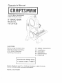
CAUTION:
Before using this Band Saw,
read this manual and folJow
÷
÷
Safety Instructions
installation
all its Safety RuIes and
Operating
instructions
÷
®
®
Operation
Maintenance
Parts List
Sears,
Visit
Part
Roebuck
our Cra_sman
and Coo, Hoffman
website:
Noot37o2141300t
Estates,
w'_Lsears.cornJcraflsman
_L 60119
U.SoAo
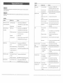
SECTION
PAGE
Warranty ......................................................................................................................................
Products Specifications
................................................................................................................
Safety instructions
.......................................................................................................................
Accessories
arid Attachments
........................................................................................................
Ca.:oR Contents ..........................................................................................................................
Know Your Band Saw ...................................................................................................................
2
2
3
6
6
7
GENERAL
SAFETY
#NSTRUCT1ONS
BEFORE USnNG THE BAND SAW
S_rlety is a combination of common sense, s_aying alert
and knowing how to use [his Band Saw.
Glossa 5, of Terms ..........................................................................................................................
8
Assembly and Adjustments
...........................................................................................................
£
To avoid misIakes that could cause serious injury, do nol
Operation
....................................................................................................................................
15
plug the Band Saw in unti! you have read and
MaiR_eRaRce
.................................................................................................................................
17
understood the following:
Troab_eshooting
Guide ..................................................................................................................
18
Parts ...........................................................................................................................................
20
1. READ and become familiar with the entire Operator's
Manual. LEARN the tool's application, limitations and
possible hazards.
2. KEEP GUARDS
FULL
ONE YEAR
WARRANTY
If this Band Saw fails due to a defect in material or workmanship
Sears wi!l at its option repair or replace it free of charge.
Return
this Band Saw
This warranty
to state,
gives
to a Sears
you specific
Sears,
Service
Center
legal rights,
Roebuck
3_
for repair,
within
one year
or to place oi: purchase
and you may aiso have other rights
and Co., Dept.
817 WA, Hoffman
Estates,
of date
of purchase,
IN PLACE and in working order.
REMOVE ADJUSTING KEYS AND WRENCHES.
Form lhe habit of checking to see that keys and
adjusting wrenches are removed Irom the tool before
turning ON.
for _-eplacement.
that may vary from
state
4. KEEP WORK AREA CLEAN.
benches invite accidents.
Cluttered
areas and
5. DON'T USE iN DANGEROUS
ENVIRONMENT.
Don't use power toots in damp or wet Iocalions, or
expose them Io rain. Keep work area we]! tighted.
tL 60179
Some dust created by power sanding, sawing, grinding, drilling and other construction act;vities contains chemicals known
to the state of California, to cause canceq birth defects or other reproductive harm. Some examples of these chemicals
are:
Lead from feed-based paints
Crysta!line silica from bricks, cement and other masonry products
Arsenic and chromium from chemically treated lumber
Your risk from these exposures varies, depending on how often you do this type of work. To reduce your exposure to these
chemicals, work in a well-ventilated
area and work with approved safety equipment such as dust masks that are specialfy
designed to filter out microscopic particles.
6. KEEP CHNLDREN AWAY. All visitors should be kept a
safe distance from work area.
7. MAKE WORKSHOP CHILD PROOF with padlocks,
master switches, or by removing starer keys.
8. DON'T FORCE THE TOOL. It wil! do the job better
and safer at the rate for which it was designed.
9. USE THE RIGHT TOOL. Do not force tool or
attachment to do a job for which it was not designed.
._otor
Power source .........
Speed ......................
Speed control ..........
Horsepower ............
Cuttip.g Capacity
Throat ..................
Height ..................
B_ade
Width ....................
Length ..................
Table
Size ....................
Tilt ......................
12-114" x 11-1t2"
0 ° - 3° Left; 0° ° 45 ° Right
Table Extension
Yes, with fence
............
120 V, 60 Hz, 3.6Amp., Ac
2480FPM (No load)
Electronic
It2HP(Max. Developed)
Sawdust blower ...........................
Net weight .................................
9"
3-112"
To avoid efectrical hazards, fire hazards, or damage to the
too!, use proper circuit protection. Use a separate electrical
circuit for your toois.
I18" to 3/8'
59" to 59_1/2"
Yes
30.8 Ibs.
This Band Saw is wired at the factory for I20V operation.
Connect to a 120V, 15 AMP branch circuit and use a 15
Amp time delay fuse or circuit breaker. To avoid shock or
fire, replace power cord immediately if it is worn, cut or
damaged in any way.
Extension fence Capacity. !2" Right
2
10.USE PROPER EXTENSION CORD. Make sure your
extension cord is in good condition, When using an
extension cord, be sure to use one heavy enough to
carry the curren_ your product wil! draw. An
undersized cord wilt result in a drop in line voilage
and in loss of power that wilI cause the tool to
overheaL The table on page 5 shows the con'ect size
to use depending on cord length and nameplate
ampere rating, If in doubt, use the next heavier gauge_
The smafler the gauge number the heavier the cord.
11.WEAR PROPER APPAREL. Do not wear Ioose
clothing, gloves, neckties, rings, bracefets, or other
jewelry lhat may get caught in moving parts. Non-slip
footwear is recornmended. Wear protective hair
covering to contain long hair.
12.ALWAYS WEAR EYE PROTECTION. Any Band Saw
can [hrow foreign objects into Ihe eyes that could
cause permanent eye damage. ALWAYS wear Safety
Goggles (not glasses) lhat comply with ANSI Safety
standard Z87.1 Everyday eyeglasses have only
impacI-resistance
lenses. They ARE NOT safety
gfasses. Sal_e[y Goggtes are available at Sears.
NOTE: Glasses or goggles not in compliance with
ANSI Z87,1 could cause serious injury
13.WEAR A FACE MASK OR DUST MASK. Sawing
operation produces dust.
14,SECURE WORK. Use clamps or a vise to hold work
when practical. It's safer than using your hand and it
trees both hands to operate tool.
15.DISCONNECT
TOOLS before servicing; when
changing accessories such as blades, bits, cutters,
and [he like.
16.REDUCE THE RISK OF UNINTENTIONAL
STARTING. Make sure switch is inOFF position
before plugging in.
17,USE RECOMMENDED
ACCESSORIES.
Consult the
Operator's Manual for recommended accessories.
The use of improper accessories may cause serious
injury.
18.NEVER STAND ON TOOL. Serious injury could
occur if the toot is tipped or if the cutting too! is
unintentionally contacted.
lg.CNECK
FOR DAMAGED PARTS. Before further use
of the tool, a guard or other par that is damaged
should be carefully checked [o determine that it will
operate properly and perform its intended function check for alignment of moving parts, binding of
moving pads, breakage of parts, mounting, and any
other conditions that may affect its operation. A guard
or other part that is damaged should be propedy
repaired or replaced.
20.NEVER LEAVE TOOL RUNNING UNATTENDED.
TURN POWER "OFF". Don't leave too[ until it comes
to a complete slop.
21 .DON'T OVERREACH.
balance at all times.
Keep proper footing and
22.MAINTAIN TOOLS W_TN CARE. Keep tools sharp
and clean for best and safest performance. Follow
instructions for lubricating and changing accessories,
23.DO NOT use power tools in the presence
flammable liquids or gases.
of
:_/_`_:_!i!:_%!_`:i!;:_:_!i:!:_?_!!ii_:!::_!i!_i_i!:_:_/:ii!:_i_i_!i:!:!_ii!_i_/ii_i_i_!ii_
_ 3 i!_ii_i_1_i_i!_i_i!i_!!!i_ii_i_:i_i_iii!_i_!!_!i_i!:_:_!_ii_/_i_i_i_i!ii_!_!i_!_!_i_
24.DO NOT OPERATE the toot if you are under the
influence of any drugs, afcohol or medication that
could affect your ability to use the tool properiy.
12. SMALL PIECES should be secured with jigs or
fixtures. Do not hand hold pieces that are so small
your fingers are under the blade guard.
ELECTRICAL
25.ALWAYS operate the band saw in a welFventilated
area and provide for proper dust removal, Use dust
collection systems whenever possibIe. Dust
generated from certain materials can be hazardous to
your heatth,
13, SUPPORT round work properly (with a V_block or
clamped to the miter gauge) 1o prevent it from rolling
and the blade from biting.
iN THE EVENT OF A MALFUNCTION
OR
BREAKDOWN,
grounding provides a pallq of least
resistance for electric current and reduces the risk of
efectric shock. This tool is equipped with an electric cord
that has an equipment-grounding
conductor and a
grounding plug, The plug MUST be plugged into a
matching receptacle that is property installed and
grounded in accordance with ALL local codes and
ordk_ances.
SPECIFIC
BAND
1.
2.
SAFETY
INSTRUCTIONS
FOR
SAWS
TO AVOID iNJURY from unexpected movement,
make sure the saw is on a firm, level surface,
properly secured to prevent rocking, Make sure there
is adequate space for operaling. Bolt the saw to a
support surface to prevent slipping, walking, or
sliding during operation.
TURN the saw OFF and unplug the saw before
moving it.
size and sue
14, CUT only one workpiece at a time. Make sure the
table is clear of everything except the workpiece and
its guides before you turn the saw on.
3.
USE THE CORRECT
4,
USE blades rated at 2480 FPM or greater.
5.
MAKE SURE the blade teeth point down and
towards the table.
6.
BLADE GUIDES, SUPPORT BEARINGS, AND
BLADE TENSION must be propedy adjusted to
avoid accidental blade contact and to minimize blade
15_ ALWAYS WATCH the saw run before each use, If
[here is excessive vibration or unusual noise, stop
immediately. Turn the saw OFF. Unplug it
immediately. Do not start the saw again until the
)roblem has been located and corrected.
16. TO FREE any jammed material, turn the switch OFF.
Remove the switch key and unptug the saw, Wait for
all moving parts to stop before removing jammed
material.
I7.
of blade.
breakage. 7o maximize blade support, always adjust
the upper blacie guide and blade guard so that it is
I/8 inch above the wed<piece.
For your own safety, read the entire instruction manual
before operating the band saw.
1, Wear eye protection.
2. Do not wear gloves, necktie, or loose clothing.
3. Make sure the saw is on a firm level surface and
4.
7.
TABLE
8.
USE EXTRA CAUTION
awkward workpieces.
9.
LOCK HANDLE
should be tight.
with large, very small or
USE EXTRA SUPPORTS to prevent workpieces
from sliding off the table top. Never use another
person to supper1 the workpiece.
10. WORKPECES
must be secured
rock or slip whiie being cut.
so they don't twist,
11. PLAN intricate and small work carefully to avoid
pinching the blade, Avoid awkward operation and
hand positions to prevent accidental contact with the
blade.
DON'T LEAVE the work area until all moving parts
are stopped. To child-proof the workshop, shut OFF:
the power to master switches and remove the switch
key from the band saw. Stere it in a safe place, away
from children,
5.
6.
7.
8.
properly secured.
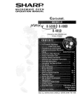
USE ONLY THE RECOMMENDED
GROUNDING
REQUIREMENTS
as the current stamped on Ihe motor nameplate.
Running at a lower voltage wilt damage the motor.
This tool is intended for use on a circuit that has a
INSTRUCTIONS
DO NOT MODIFY THE PLUG PROVIDED.
the receptacle, have the proper receptacle
quatifiecl electrician.
If it wilt not fit
installed
by a
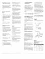
receptacle like the one illustrated in Figure A,
Figure A shows a %prong electrical plug and receptacle
[hat has a grounding conductor. If a properly grounded
receptacle is no[ available, an adapter (Figure B) can be
used to temporarily connect this plug to a 2-contact
grounded receptacle. The temporary adapter should be
useci only until a properly grounded receptacle can be
installed by a quafified technician. The adapter (Figure B)
has a rigid lug extending from it that MUST be connected
to a permanent earth ground, such as a properly
grouncted receptacle box. The Canadian Electrical Code
prohibits the use of the adapters.
IMPROPER CONNECTION
of the equipment-grounding
conductor can result in risk of electric shock. The
CAUTION: In all cases, make certain the receptacle is
properly grounded. If you are not sure, have a qualified
electrician check Ihe receptacle.
conductor with green insulation (with or without yeilow
stripes) is time equipment-grounding
conductor, if repair
or reptacemenl of the electric cord or plug is necessary,
DO NOT connect the equipment-grounding
conductor io
a five terminal
This tool is for indoor use only_ Do not expose to rain or
use in damp locations.
CHECK with a qualified electrician or service person if
you do not completely understand the grounding
instructions, or if you are not sure the tool is properly
grounded.
Fig. A
USE ONLY 3-WIRE EXTENS{ON CORDS THAT HAVE
3-PRONG GROUNDING PLUGS AND 3-POLE
RECEPTACLES
THAT ACCEPT THE TOOL'S PLUG.
REPAIR OR REPLACE DAMAGED OR WORN CORD
iMMEDIATELY.
GU_DEUNES
FOR EXTENSION
Fig. B
CORDS
prevent accidental injury,
Do not remove jammed cutoff pieces until rise blade
has stopped.
Maintain proper adjustment of Made tension, blade
guides and thrusi bearings.
9, Adiust upper guide to just clear the werkpiece,
t0. Hold the werkpiece firmly against the table,
....
€-_.....
c_rounamg Lug I_-g_C.._
ACCESSORIES.
Use extra caution with very large, very small, or
awkward workpieces.
Keep hands away from the blade at ati times to
3-Prong Plug
USE PROPER EXTENSION CORD. Make sure your
extension cord is in good condition. When using an
extension cord, be sure to use one heavy enough to
carry the current your product will draw, An undersized
cord will cause a drop in line voltage, resulting in loss of
power and cause overheating. The table below shows
time correct size to use depending on cord Iength and
nameplate ampere rating. If in doubt, use the next
heavier gauge. The smaller the gauge number, the
heavier the cord.
Be sure your extension cord is property wired and in
good condition, Always replace a damaged extension
cord or have it repaired by a qualified person before
using it_ Protect your extension cords from sharp objects,
excessive heat and damp or wet areas.
Use a separate electrical circuit for your tools. This circuit
must not be tess than # 12 wire and should be protected
with a 15Amp time delay fuse. Before connecting the
motor to the power line, make sure the switch is in the
OFF position and the electric current is rated the same
is Connected to a
Known Ground
__
2-ProngSure This
Make
Receptacle
_
This tool must be grounded white in use to protect the
operator from electrical shock,
Ampere
Morethan
(When using 120 volts only)
Rating
[Tota] length of cord in feet
25'
50'
100'
150'
o
not more than
6
, 18
16
16
14
[ 6
I 10
10
j 18
16
t4.
t2
12
12
16
"i 16
14
I6
12
not recommended
14
12
RECOMMENDED
ACCESSORIES
To avoid iniury:
Use only accessories recommended for this band
saw.
Follow instructions that accompany accessories. Use
of improper accessories may cause hazards.
o Use only accessories designed for this band saw to
avoid injury from thrown broken parts or workpieces.
Do not use any accessory unless you have
completely read the instruction or operator's manual
for that accessory.
Visit your Sears Hardware Departmen[ or see the Sears
Power and Hand Tool Catalog for the foIIowing
accessories:
iTEM
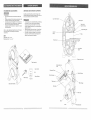
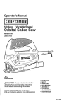
UNPACKING
AND CHECKING
CONTENTS
Carefully unpack [he band saw and all its parts, and
compare against the illustration following. Place the saw
on a secure surface and examine i[ carefully.
Upper blade wheel
Blade guard
o
To avoid injury from unexpected starting, do not plug
the power cord into a power source receptacle
during unpacking and assembly. This cord must
remain unplugged whenever you are assembling or
adjusting the saw.
Although compact, this saw is heavy. To avoid back
injury, get help whenever you have to lift the saw.
If any part is missing or damaged, do not plug the
band saw in until the missing or damaged part is
replaced, and assembly is complete.
Upper blade
support bearing
Upper blade guide
ON/OFF
switch
__.__f_._-_--
Blade width: 1/8" to 3/8"
Blade length: 59" to 59_1/2"
Wheel
Blade
brush
Lower blade
wheel
Blade tension
knob
Table Assembly
Upper guide lock
knob
Hex. Wrench
Extension
Fence
Sawdust
Bolt
blower
Table Extension
Spring Washer
Miter Gauge
Hex. Nut
Table insert
Miter storage
Band Saw Assembly
Work table
--
Motor
Base
7
Motor cord
BAND
SAW TERMS
BLADE GUIDES -- Support the blade and keep it Item
twisting during operation. Blade guides must be adjusted
when blade is changed or replaced.
UPPER GUIDE LOCK KNOB -- locks the upper slide.
Use it after adjusting the upper guide assembly to make
sure upper blade guide just clears workpiece before
cutting. Upper guide lock knob must be tighlened before
the band saw is turned on.
TABLE
LOCK
KNOB
--
KERF -- The material removed by the blade in a Ihrough
cut, or the slot produced by the blade in a non-through or
partial cut.
ASSE ]BLY
TOOLS
NSTRUCT ONS
NEEDED
LEADING EDGE -- The front edge of the workpiece
pushed into the cutting tool first,
Phillips screwdriver
MITER CUT -- An angle cut made across the width of a
workpiece.
RESAW -- A cutting operation to reduce the [hickness
Ihe workpiece to rnake thinner workpiece.
of
Adjustable wrench
Combinatior_
squ_qre
Straight edge
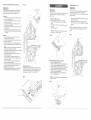
SAW[3UST COLLECTION PORT (F_G. C)
This band saw wilt accept a hose or vacuum accessory
(not provided) to be connected to the port (1) on the right
side of base. If excessive sawdust buitdup occurs inside
the base, use a wet/dry vacuum cleaner or manually
remove sawdust by removing the screws on the right side
of saw. Reattach the metal plate and screws before
starting the saw. This wilt keep your saw cutting
efficiently.
Fig. C
locks the tame in place.
RESIN -- A sticky sap that has hardened.
TiLT (BEVEL) SCALE -- shows the degreethe lable is
tilted for bevel cutting.
BLADE TENSION KNOB -- controls the amount of
blade tension when changing blades.
BLADE TRACKING KNOB -- adjusts blade position so
blade atways runs in the center of the wheel.
SAWDUST PORT -- helps keep the machine free from
sawdust. The sawdust port rnakes an excellent hook_up
for a wet/dry vacuum.
ON/OFF SWITCH -- has a built-in child salely lock. Te
Jock the switch in the OFF position, remove the switch
key from the switch.
WOODWORKING
TERMS
BEVEL CUT -- An angle cut made through the face of a
workpiece.
COMPOUND CUT -- A simultaneous bevel and miter
cut,
RIPPING CUT -- A cutting operation along the iengih of
the workpiece.
R,RiVi. -- Revolutions per minule. The number of kJms
completed by a spinning object in one minute.
SAW BLADE PATH -- The area of the workpiece or
table top directly in line with the travel of the blade or the
pa_t of the workpiece that wilt be cut,
SET -- The distance between two saw blade teeth tips,
that are bent outward in opposite directions to each other.
The further apart the tips are, the greater the set.
TRAIUNG EDGE -- The workpiece edge last cut by the
blade.
WORKPIECE _ The item being cut. '[he surfaces of a
workpiece are commonly referred to as faces, ends and
edges.
WORKTABLE -- The surface on which the workpiece
rests while performing a cutting or sanding operation.
For your safety, never connect ptug to power source
receptacle until all assembly and adjustment steps are
completed, and you have read and understood the safety
and operating instructions.
BLADE STORAGE (F_G, B)
The right rear side of the body (1) has a slot (2) designed
to store the miter gauge (3).
Fig. B
ASSEMBUNG THE TABLE (F_G. [3)
!. Remove the table aligning screw (1) from the table
(2).
2. Guide the table slot (3) over the saw blade and rotate
a 1/4 turn, so the slot is perpendicular to the flat side
of the blade.
3.
4.
5.
Insert three bolts (4) through the table holes, place
spring washers (5) and hex nuts (6) on the bolts. Do
not tighten.
Align the 0 ° mark on the scale to the pointer on the
support bracket.
Place the table aligning screw (1) in the front of the
table, in the slot (3), and tighten.
Fig. D
CROSSCUT -- A cut made across the width of the
workpiece.
Leading
RAM. -- Feet per minute. Used in reference to the
surface speed of the saw blade.
Kerr
Sawblade Path
!
FREE HAND -- Performing a cut without using a fence
(guide), hold-down or other proper device to prevent the
workpiece from twisting during the cutting operation,
Surface
3
GUM -- A sticky sap_based residue from wood products.
Workpiece
HEEL -- Misalignment of the blade.
Trailing Edge
INSTALLING
ANDREMOVING
BLADES
(FIG.E)
Fig. E
BLADE
Toavoidinjuryfromaccidental
stalling,alwaysturnthe
switchOFFandremove
powercordplugfrompower
soclrce
beforeremoving
orreplacing
theblade.
Installing
1. MakeSLUe
thebladetensionknob(1)isturned
counterclockwise
untilitstops.
2. Remove
thetablealigning
screw(2)fromthetable.
3, Openthewheelcover.
4., Guidethenewblade(4)through
thetableslot(8),
makingsurethebladeteetharepointing
forward
and
down.
NOTE:Toavoidliftingtheworkpiece,
thebladeteeth
mustpointdownward
towardthetable.
5. Swinging
theleftsideawayandback,placetheblade
ontheupperandlowerwheels(7),
6. Placethebladecarefully
between
theupperand
lowerbladeguides(5),
7. Slidethebladeintothestot(6)attheleftofthe
wheels,
andmakesurethebladeispositioned
atthe
middleofthewheels,
8. Instal/thebladeguardbythreading
thetwoblade
guardmounting
screwstightly.
9. Turning
thebladetensionknobclockwise,
tighLen
the
tensionuntil[hebladeistightonthewheels.
10.Replace
thealigning
screw(2).
11.Adjustthebladetracking
andtensionproperly
(See
ADJUSTMENT)
beforeoperating
thebandsaw.
1,
TILTING THE TABLE (FIG. G)
The band saw table (1} tit_s 0 '_to 45 ° to Ihe right
1. Loosen the handle lock knob (2) underneath fhe
lable,
2.
3.
(FIG. 1)
To avoid injury, turn the switch OFF and disconnect the
saw from the power source before making any
adjustmenls.
NEVER make tension adjustments with the
machine running.
To avoid injury, turn the switch OFF and unplug the band
saw from Ihe power source before making any
adjusImenls_
Removing
1. Loosen
thebladetensionbyturningthebladetension
knob(I) counterclockwise.
2. Remove
thetablealigning
screw(2)fromthetable.
3. Openthewheelcover.
4. Loosen
thetwobladeguardmounting
screws
and
remove
thebladeguide(5).
5, Carefully
pulltheMadefrom[hesideslot(6)andfrom
thewheels(7).
6. Swingtheleftsideof_hebladetowardyou,turning
thebladesoil willfitthroughIheslot(8)inthetable,
andremove.
TENSION
2.
Tilt the tabIe to the desired angle as shown on the
scale (3).
Tighten the tock knob.
Turn blade tension adjusting knob (1) clockwise until
blade (2) is tensioned.
Blade tension can be checked by pushing on the
blade. The blade should move slighHy with firm finger
pressure.
NOTE: Over tensioning the blade may cause breakage.
Too Iittle tension may cause the blade to slip on the
wheels.
NOTE: The 90" table stop bolt mLIS[ be removed to
tilt Ihe table 10 ° or more the left.
Fig. I
J
MITER GAUGE (FIG. F)
A miter gauge (1) is supplied with your band saw to be
used with the table (2). The table is equipped with a slot
on the right side of the blade for the miter gauge, The
miter gauge can be tilted 0° to 45'* right or left.
ADJUSTING THE 90 ° TABLE STOP (FIG. H)
1. Loosen table tilting lock knob (1).
2. Place a combination square (2) or level on the table
with one end of the square against the blade,
3, Tilt table until the top table surface is at a'90 ° angle to
the blade and tighten the table tilting lock knob.
4. Using the wrench (3) supplied, turn the set screw (4)
until the screw touches the frame.
5. Set the table tilting pointer to line up with the zero
mark on the table turning.
NOTE: The table stop bolt must be removed to tilt the
table up to 30 left.
Fig. H
I
/
!
\
:
:::: :
:
:: :]:
:::::: ::
;:
:
11
::
:::: ::
::::
:
:::;;::::
2
BLADE TRACKING
{FIG. J)
UPPER BLADE
To avoid injury, turn the switch OFF and disconnect the
saw from _he power source before making any
adjustments. Never make tracking adjustments with the
machine running.
1. The blade (1) must be tensioned properly before
adjusting the tracking. (See BLADE TENSION on
page 11).
2. Open [he wheel cover.
3. Move the blade guides (2) and support bearings (3)
away from the blade, if necessary. (See page 13).
4_ Rotate the wheel (4) slowly fox,yard by hand, and
check the position of the blade on the wheel. The
blacle shoutci remain centered on the wheeI as it
turns,
5.
6.
if the blade moves toward the front of _he wheel, turn
the tracking knob (5) on the rear of the band saw
clockwise. This tilts the top of the wheel and rnoves
the blade toward timecenter.
tf [he blade moves toward the back edge, turn the
tracking knob counterclockwise,
moving the blade
toward the center.
NOTE: TLIm the tracking knob SLIGHTLY
blade [racking adiustments.
to make
Fig. J
GUtDE ASSEMBLY
(FIG. K)
To avoid injury, turn the switch OFF and clisconnect the
saw from the power source before making any
adjustment. NEVER make adjustments with _he machine
running
1.
2.
Loosen the lock knob (1) and move the blade guide
assembly (2) [o 1/8" above the workpiece.
Rotate the assembly, ff necessary, unliI the guide
blocks (2) are Ilat (parallel) to the blade (4). Tighten
the lock knob.
Fig, K
UPPER BLADE GU!DES AND BLADE SUPPORT
BEARING (FIG, L, M)
TtTe blade guard has been removed for cladty of
illustration. To avoid injury never operate the band saw
without all guards in place and in working order.
To avoid injury, turn the switch OFF and disconnect the
saw from the power source before making any
adjustments. NEVER make adjustments with Ihe machine
running.
NOTE: Maize sure the blade is tensioned and tracking
properly. Adius[ the blade guides and support bearing
alter eacb Made tension and tracking adjusIment. When
the upper blade guides and support bearings are
adjusted, the lower guides and bearings should also be
adjusted.
Support bearing (Fig. IVl)
8. Loosen the screw (6).
9. Move the support bearing (8) in or out, until the
bearing is 1/64." behind the blade.
16. Tighten tile screw (6).
NOTE: The blade supporl bearing prevents the blade
from moving back too far and damaging the saw teeth
setting.
11. Check the lateral
The vertical back
overlap the front
1/8" to the [eft el
Fig. M
Blade guides (Fig. L)
1. Make sure the blade is tensioned and tracking
properly.
2. Loosen the front hex sockeL screws (1) with a hex
wrench.
3. Move the guide blocks (2) as close to [he blade (2) as
possible without pinching it.
4. Using a feeler gauge, make sure the space between
guide block and blade measures 0.02" (the thickness
of a dollar bill).
5. Tighten the hex socket screws.
6. Loosen the side screw (4) by turning counter
cJockwise.
7. Tigilten the screw.
\
I
3
\
\
,\
\\
5
\
4
\
\
8
6
Fig. L
\
position of tile support bearing (8).
edge of the blade (3) should
face of the support bearing 1/16" to
the right bearing edge, as shown.
LOWER BLADE
(FIG. N, O)
GUIDES AND SUPPORT
BEARING
Fig, N
BASIC
To avoid injury, turn the switch OFF and disconnect the
saw from the power source before making any
adjustments. NEVER rnake adjustments with Ihe machine
running.
"ON/OFF" SWITCH (FIG. P)
The key swiLch is inlencled to prevent unauthorized LISBOf
the band saw.
1. To turn the band saw ON insert the yelIow key (1)
into the key slot (2) in the center of the switch.
2.
Push the key firmly into the stot, then push switch Io
the ON position to slart the band saw.
3.
To turn the band saw OFF push the switch to the
down position.
4.
Remove the yellow switch key, when the saw has
come to a complete stop, by gently pulling it outward.
NOTE: Make sure the blade is tensioned and tracking
property. The lower blade guides and support bearing
should always be adjusted after the blade is tensioned,
the tracking is adjusted, and the upper blade guides and
upper support bearings are properly adjusted.
Blade guides
!.
Loosen belb fron_ hex socket screws (1) with a bex
wrench.
2.
Move the guide blocks (2} as close to the sides of the
blade (3) as possible without pinching it.
Using the feeler gauge, measure the spaces between
the guide blocks and tbe blade. Adjusl to 0.02".
Tighten the hex screws (Fig. N)
Loosen _he side hex socket screw (4). Move the
guide block support bracket (6) in or out until _he
blocks are just behind the saw teeth. Tighten the
screw. (Fig. O)
3.
4.
5.
Support bearing
6. Loosen the bearing hex socket screw (7) with the hex
wrench.
7.
Move the blade supped bearing shaft (8) in or out
until the support bearing (9) is 1/64" behind the saw
blade.
8.
9.
Tighten the bearing hex socket screw. (Fig. O)
The back edge of the blade (3) should be positioned
1//16" to 1/8" from lhe right edge of the support
bearing (9), as shown. (Fig. N)
SAW OPERATIONS
Remove the switch key whenever [he saw is not inuse,
Place it in a safe place and our of the reach or children.
Fig° P
GENERAL
CUTTING
For your safety, read and understand
SPECIFIC SAFETY INSTRUCTIONS
before using the band saw.
all GENERAL and
on pages 3-5
Operating a band saw involves a certain amount of
hazard. Before attempting regular work, use scrap lumber
!o check the settings, and to get the feel of operating Ihe
band saw. Read instructions and plan your work before
cutting a workpiece.
Do not turn Iine power ON until after you have
adjusImenIs, checked that the guard is place,
the wheel by hand to make sure all parts work
Always keep the guide assembly close to your
above the workpiece.
made all
and Iurned
properly.
work, It8"
Do not force the workpiece against the blade. Light
contact permits easier cutting and prevents unwanted
friction arid heating el the blade.
Sharp saw blades need little pressure for cutting. Steadily
move the workpiece against the blade without forcing it.
Fig, O
To avoid twisting the blade, do not turn corners or saw
around corners.
A band saw is basically a "curve-cutting" saw. It is not
capable of doing intricate inside cutting as can be done
with a scroll saw.
4
/
USING THE TABLE EXTENSION (F_G. Q)
NOTE:
A. For ripping 5-3/4" _ 7_t/2" workpiece, the extension
fence has to be installed in the IN-RIP position (Fig.
Q). Remove the Iock handles (1) and fence. Place the
fence on extension table as shown. Raise the fence
to a position that just clears the table surface and
secure in ptace using loci< handles (1) for IN-RIP
position.
B. For ripping 7-It2" _ 12" workpiece, the extension
fence has to be installed in the OUT-RIP position.
\
8
1.
2,
,,7
3.
Release both cam locking levers.
Slide the table extension on tlqe side your workpiece
will be needing support, and tighten both cam loctdng
levers.
Slide the extension out until the correct measurement
is displayed on the tube scale.
Fig. Q • ....
It is also used for straight line operations such as
crosscutting,
ripping, mitering, beveling, compound
cutting and resawing.
To avoid blade breakage, fire or other damage or injury,
NEVER use this band saw to cut ferrous metals.
CVTTING CURVES
When cutting curves, carefully turn the workplace so the
blade follows without twisting. If the curve is so sharp that
you repeatedly back up and cut new kerr, use a narrower
blade, or a blade with more set (teeth further apart),
When a Made has more set, [he werkpiece turns easier
but the cut is rougher.
When changing a cut, do not withdraw the workpiece
from the blade; the blade may get drawn off the wheels.
To change a cut, turn the workplace and saw out through
the scrap material area.
When cutting
along.
long curves,
make relief cuts as you go
CIRCLE
CUTTmNG
(FIG,R)
1. Adiusttheguideassembly
to1/8"abovethe
workpiece.
2. Usebothhandswhilefeedingtheworkintotheblade.
Holdlheworkpiece
firmlyagainst
theLaMe.
Use
gentlepressure.
Donotforcethework,allowthe
bladetocut.
S. Thesmallest
diameter
circlethatcanbecutis
determined
bythewidtiloftheblade.Forexampte,
a
I/4"wKlebladewil!cuta minimum
diameter
of
approximately
1_1/2".
Common
causes of blade breakage:
e
Poo guide a ignrnent and adjustment
¢
Forcing or twisting
radius.
e
Feeding too fast.
¢
Dull leeth of not enough seL
GENERAL
a wide blade around a short
ADJUSTING THE UPPER BLADE GUIDE TRAVEL
(FIG. T)
If the upper guide bar assembly will not move up and
down easily or falls when the lock knob is loosened,
the foilewing adjustments should be pedormed.
MAINTENANCE
For your own safety, turn the switch OFF and remove
lhe plug from [he power source receptacle before
maintaining, cleaning, adjusting, or lubricating your
saw,
@
Too much blade tension.
÷
Setting fop guide assembly
workpiece.
Fig. R
2-1fZ'O
Circle
C'iametef
Blade
Widfh
¢
Lumpy or improperly
blade.
@
Continuous
too high above the
finished braze or weld on the
Recommended
Blade
Width..._
......
1/4, 3/8, I/2
1/4, 3/8, 1/2
1/4, 3/8, I/2
I/4, 3/8, 1/2
Compound Cutting
Circle Cutting
SELECTION
(HG.
S)
r
Move the guide (3) up and down to check for
smooth movement and ability 1o hold its position.
Make further adjustments to the screw as
required. Properly adjusted, the guide bar should
move smoothly and hold ils position when
released.
Reinstall
Fig. T
BAND SAW
Sawdust wilt accumulate under the table and base.
This could cause difficulty in the rnovement of the
table when setling up a band saw cut. Frequently
bIow out or vacuum up the sawdust.
I
Do not allow filth to build up on the table, the guides,
or the support bearings. Clean them with Craftsman
Gum and Pitch Remover.
CAUTION: Blade teeth are sharp. Use care when
handling a saw blade.
For longest wear and besL cutting results, use the correct
blade thickness, width, and temper for the type of material
you wi{l cut.
NOTE: Do not immerse the support
gum and pitch remover.
bearings
in the
LUBRICATION
All of the bearings are packed with grease at the
factory. They require no further lubrication.
Put a thin coat of paste wax on the table so that the
wood slides easily while cutting.
When sawing small curves and delicate work, use narrow
blades. Otherwise, use the widest blade possible_ See
Fig, R,
BLADE WHEEL
TIRES
CAUTION; Never put lubricants
is spinning.
Pitch and sawdust that build up on the tires should be
removed with a stiff brush or scraped off with a piece
of wood.
For cttting wood and smlar materials with this band saw,
purchase blades in widths up to t/2", and a length of 59"
to 59-1/2".
NOTE: To avoid damaging the tires do not use a
sharp knife or any kind of solvent.
Do not cut metals with this band saw.
When the tires become worn they should be replaced.
When replacing the tires, stretch them around the
wheels but do not glue them on.
[qOTOR
Frequently blow or vacuum out any sawdust from the
motor. Follow lubrication instruction on the motor
label.
To avoid electrocution
worn, cut or damaged
: :
'::::
=:
16
'
!
i
the guide bar lock knob.
Keep your band saw clean. Rernove the sawdust
from the inside. Vacuum or blow out frequently.
See char on thispage
t/8, 1/4
Curve Cuttirtg-
3.
4.
To avoid eye injury from blowing debris, wear safety
goggles when blowing out sawdust.
Fig. S
._C[oss Cutting
Mitering
Beveling
Remove the guide lock knob (1)
Tighten or loosen the screw (2) located behind
the lock knob.
5.
running of blade when nol cutting.
%;;;;;0;;
............
]
BLADE
To avoid fire or toxic reaction, never use gasoline,
naphtha, acetone, lacquer thinner or similar highly
volatile solvents to clean the band saw.
1.
2.
:
or fire, immediately
power cord.
replace a
17
::::::::::::::::::::::::::::
on the blade while it
MOTOR
Problem
[Probable
Noisy operation.
To avoid injury from an accidental
making any adiustments.
start, turn the switch OFF and remove the plug from the power source before
Cause
|
. Incorrect belt tension.
1. AdjusE
tension. See
ASSEMBLY
ADJUSTMENTS
section
INSTALLAND
THE BELT.
1
2. Readjust and tighten motor pulley set screw.
2. Loose motor pulley.
3, Loose pulley cover.
Vlotor will not start,
All electrical or mechanical
Service Center.
repairs should be done only by qualified
service technicians.
• [',lot plugged
Contact the nearest Sears
3. Readjust
into power
Insert key and turn the swkch ON.
3, Motor cord cut or abraded.
3.
Take to Sears Service Center for new cord.
4. Plug on cord is faulty.
4.
Take to Sears Service Center for new plug.
5. Fuse on circuit breaks open.
5.
Re-set; may be too many machines
6. Faulty motor.
6.
Take to Sears Service Center for repair or
position,
Probable
Cause
__
[Remedy
I.
• Not tracking properly.
center of the upper wheel.
............................................
Adjust tracking.
ADJUSTMENTS
Defective
Band saw slows down
Plug it into the power outlet.
2.
GENERAL
Blade does not run in the
screws,
outlet.
Switch and key not in ON
i
Problem
and tighten pu{ley cover mounting
blade.
See ASSEMBLY
AND
section BLADE TRACKING
replacement,
2.
Replace blade.
t
Adjust belt tension. See ASSEMBLYAND
Motor
I. Belt too loose.
on line,
1. Too many electrical
1,
Turn off other machines
and try again.
i
rated fuse or circuit breaker.
ry time delay fuse, or go to circuit with higher
Unptug and turn wheels by hand, move
machines.
when cutting
ADJUSTMENTS
2. Cutting too small a radius.
2.
Stop feeding,
section BLADE TENS!ON.
2. Incorrect fuse.
back up the material slightly, until
the band saw speeds up.
3. Dull blade.
4, Over oad ng motor.
3. Wheels do not rotate.
obstruction.
3.
Replace blade.
4.
Slow down, trying to cut too fast. See MOTOR
TROUBLESHOOTING
4. Undersized
extension
cord,
4,
Use correct size extension
cord; see page 5.
5.
Cord, plug, or motor need repair; take to Sears
GUFDE on page 19.
5. Short circuit.
Service Center for repair.
BIades braking
1. Too much tension on the
1, Adjust tension. See ASSEMBLY AND
blade.
ADJUSTMENTS section BLADE TENSION
2, Kink in the blade caused by
2. Use correct cutting technique.
cutting too small a radius or
Motor faiIs to develop full
1.
Low line voltage.
1.
Check power line for proper voltage.
)ower.
2,
Faulty motor or capacitor.
2.
Take to Sears Service Center for evaluation,
Motor overheats.
t.
Overload
1.
Reduce load to motor, feed work slower into
2.
Poor ventilation
See OPERATION section GENERAL CUTTING.
1. Blade guides set too close to 1.
Adjust upper and lower blade guides.
Motor stalls or slows
2. See OPERATION
t, Too much tension on motor I1.
belt.
[
Adjust according
ADJUSTMENTS
Unplug and clean out around motor; provide better
air circulation.
3.
Take to Sears Service Center for repair.
1.
Reduce load to motor, feed work slower into
Motor overload.
2.
Low line voltage.
section BLADE SELECTION.
3.
Loose wire connections.
2.
to ASSEMBLY
4.
Faulty motor.
3• Take to Sears Service Center for repair,
{-
saw vibrates.
2.
1.
the teeth,
Band
blade.
circulation.
when cutting
2. Cutting incorrect material•
of motor.
Provide better air
turning the material too fast
Blade dulls too quickly.
on motor.
section,
AND
INSTALL THE BELT.
Frequent blowing of fuses
1.
Motor overload.
or breaking
2.
Overload
3.
Incorrect fuse or circuit
circuit,
breaker,
of circuit
btade.
Check power line for proper voltage.
4.
Take to Sears Service Center for repair,
1.
Reduce load to motor, feed work slower into
of e{ectrical
blade.
Too many electrical appliances
231
Have electrician
on same circuit.
upgrade service to outlet.
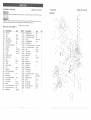
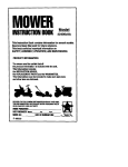
CRAFTSMAN
9" BAND
SAW
MODEL
9" BAND
NO. 137.2t4130
SCHEMATIC
_ODEL
SAW
NO. 137.214130
A
When servicing use only CRAFTSMAN repiacement parts. Use of any ether parts many create a HAZARD or cause
product damage.
Any attempt to repair or replace electrical parts on this Band Saw may create a HAZARD Lmless repair is done by a
qualified service technician. Repair service is available at your nearest Sears Service Center.
Always order by I.D, Number.
PARTS
LiST
FOR
SCHEMATIC
I.D.
Description
X089
MAIN BODY
X08T
X08S
BASE
BASE
A
Size
Qfx LDo
Descdgfion
Size
1
X07Z
TURNNING KNOB
RED
Qi'
1
RIGHT
LEFT
l
1
X07Y
TURNNING KNOB COVER
RED
1
X09J
HEX. SCREW WiI WASHER
1/4
2
XOA9
FLAT WASHER
3/8"19"2T
4
X08C
PULLEY
MAINDRIVER
1
XOAC
SPRING WASHER
3/8
4
HEX, SCREW
3/8"1"
4
X09U
X07U
SCREW(HEADLESS)
90r_CONNECTOR
M4"10
X09V
2
1
X08A
SHAFT OF LOWER WHEEL
I
X083
OUTERCOVEROFMAINBODY
SLIVERGRAY
t
X0gH
NYLON NUT
1/2
1
X03N
CR,HD.SCREWWtl WASHER
3/16xl/4
1
XOSP
WASHER
18"12.2"0.5T
4
X095
LABEL
BLADE
I
X07X
P.D. BELT
9,5"130XL
1
XOA7
FLAT WASHER
5/16"16"1
1
X082
PULLEY
TEETHTYPE
1
X084
SEWITCH PLATE
X065
POWDER COPPER
2
X13G
BLIND RIVET
4"8L
4
X08M
LOWER WHEEL
9"
1
XOA3
SWITCH
J-9303 4P
1
X08E
TIRE
PU
2
X08H
HINGE
XOJT
BEARING
6201ZZ
2
X099
BLIND RIVET
X04N
X08K
C-RtNG
SLIDING HOLDER
S-12
2
1
X08F
SPRING CLIPER
X08J
BOLT
145m/m
1
X13A
X08G
KNOB (RED)
SPRING PLATE
X031
SPRING PIN
3*20
I
X02F
PLASTIC BRUSH
1
X08B
SHAFT OF UPPER WHEEL
1
X02V
Y TYPE BLOCK
1
X09G
NYLON NUT
!
X02K
CR.HD,SCREWWiI WASHER
3f16xl/4
!
X07W
SLIDING PLATE
1
X091
NAMEPLATE
CRAFTSMAN
I
X09X
CR,HD,SCREWW'ttWASHER
1/4"3/8
4
X093
WARNING STICKET
GB
1
X08L
UPPER WHEEL
9"
t
X08P
BLADE
59-1/4"1/4
1
X03J
FLAT WASHER
5/16"18
2
X04Q
HEX. WRENCH
3M
1
X08X
SPRING
9"13.4"65L
I
XI3K
FLAT WASHER
14"22"1T
I
X07R
QUICKADJUSTINGBRACKET
RED
1
X09R
SELF-TAPPEDSCREW
3/16"3/8
3
X13L
QUICKADJUSTINGBUTTON
RED
1
XOA8
FLAT WASHER
3/!6"t2
3
XOAH
CONDENSER
181JFi250V
1
318
XO93
1
_\02F
2
4"6,4L
4
XOglJ
2
I/4
X08C
2
2
X08P
xo4q ,..
20
•
::
: "
: ,:
2!
,
""
:::::
::
: :
: :::
:::
:
: : :
::::::
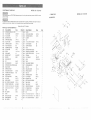
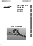
CRAFTSMAN
9" BAND
SAW
MODEL
NO. 137o2!4130
9 '_ BAND
When servicing use only CRAFTSMAN replacement parts. Use of any other parts many create a HAZARD or cause
product damage.
SCHEMATIC
MODEL
SAW
NO. !37.2!4!30
B
Any attempt to repair or replace electrical parts on this Band Saw may create a HAZARD unless repair is done by a
qualified service technician. Repair service is available at your nearest Sears Service Center,
Always
PARTS
LiST FOR
SCHEMATIC
order by I.D. Number.
B
Size
Qty i.D.
LD.
Descripfion
X12V
X13J
X03G
EXTENSION WING (FULL SET)
FLAT WASHER
3t8"20"2T
FLAT WASHER
1/4"I6
1
2
3
X09E
BUTTERFLY NUT
1/4
1
X08Z
X08Q
STAR KNOB (red#23)
ADJUST GUIDE
1t4"1-1/2
GEAR TYPE
I
1
X09P
XOHV
CARRIAGE SCREW
TEETH GUIDE BOLT
1/4"2-1/2
BIG
!
1
X080
XOAB
X08W
TRUNNING BUTTON
FLAT WASHER
SPRING
RED#23
1/4"12
1.2"11,5"I4.5L
2
2
2
X090
X087
X03V
KNOB (red#23)
BEARING SHAFT
BEARING
1/4
45L(SHORT)
626ZZ
X086
BLADE BRACKET
X09B
KEY
5x5x25
2
X09A
X092
)(088
KEY(45GRADIENT)
5x5x25
EXTENSION WING W'ARNINGLABEL
BLADE GUARD
2
I
1
X094
X09Y
X07V
WARNING STICKET
CROSS }-lEADSCREW
TRUNNION FIXTURE BOLT
3/16xl/4
6*63
1
2
1
X08N
X081
XOA4
XOA6
TABLE BRACKET
TEETH GUIDE BOLT
NYLON NUT
VVAVEWASHER
SMALL
6,5"1271
6,4"!1"0.3
1
!
!
I
X09W
HEX. SCREWWll WASHER
1/4"I-I/4
1
X02H
X07Q
X07K
X08U
X09M
COPPER POINTER (RED)
EXTENSIONTUBEWll CLAMPHANDLE
MY-2000P
BLACK(R)
EXTENS]ON WING FIXED TUBE
20*40*289L*lT
TUBE
HEX, SCREW
20*40
1/4"3/4
!
1
1
2
2
X07L
X09Y
XOAC
X09V
PLATE
CA. RE. HD. Screw
SPRING WASHER
HEX. SCREW
3li6"t/4
318
3/8"1"
I
I
4
4
Description
Size
©fy
XOAE
MOTOR
!
g03L
CROSS HEAD SCREW
3t16"1/4
1
X09S
_(07T
_0A0
SCREW(HEADLESS)
BLOWER
CLIP
1/4"3t8
8
1
4
g03N
CR.HD.SCREWWll WASHER
3/I6' 1/4
4
,_027
_02L
/,0A2
TOOTH WASHER
COPPER WASHER
PLATE
M5
BiG
2
2
I
<096
<01W
EXTENSION WING SCALE
STRAIN RELIEF BUSHING
6N-4
2
2
2
XOAG
XOA1
XOA9
POWER CORD W/I PLUG
TERMINAL
FLAT WASHER
SJTIS'3C'23M75_CI
A3
3
3t8"19"2T
4
2
X08Y
X08R
KNOB
TABLE
M4*10(RED)
X08D
X09T
X09L
X09N
TABLE INSERT (RED#23)
SCREW(HEADLESS)
HEX. NUT
HEADLESS SCREW
1/4.'3/4
1/4
1/4"l-I/4
1
1
1
3
XOAD
X09K
X09Q
x13g
SPRING WASHER
HEX, NUT
CARRIAGE SCREW
FLAT WASHER
1/4
!/4
M6"18
M6"13"1
3
3
1
t
X09D
X08V
BUTTERFLYNUT
MITER GAUGE ASSEMBLY
M6
1
1
X097
X098
TABLE SCALE
TABLE SCALE
LEFT
RIGHT
1
t
_09C
OPERATOR'SMANUAL
137.214130
1
X07P
>(09Z
_09F
g07N
EXTENSION TUBE
CA. RE. HD. Screw
NUT
BLACK(L)
M6"!0
1/4
LEFT EXTENSION TUBE WIJ NUT
518*270L*I.4T
1
4
2
!
RIGHT EXTENSION TUBE WII
518*270L*1.4T
3t16x!/4
!
2
X09V
X0,AC:
1
2
XOSV
2
1
XOTP
X_dgU
xogs
[2:
_,07M
_02K
NUT
CA. HD.SCREWWtlWASHER
Xl3,t
X0!t2
X09C
i
i
%
%,.
:; : :::
:
:
:
22
:<::
:
::
::
: ::::
: :
:
:::
:
23
: