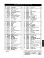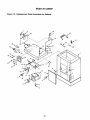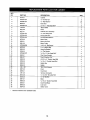
1
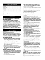
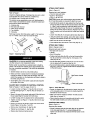
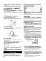
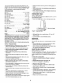
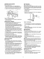
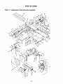
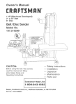
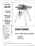
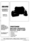
CRRFTSMRN
Operator's
Manualo
6 x 48" Oscillating Belt
12" Disc
SANDER
Model No.
351.226061
CAUTION: Read and follow
all Safety Rules and Operating
Instructions before First Use
of this Product.
Sears, Roebuck and Co., Hoffman Estates, IL 60179 U.S.A.
17985.00 Draft (01/18/02)
I
Warranty .......................................
• Proper electrical receptacle should be available for tool.
Three prong plug should be plugged directly into properly
grounded, three-prong receptacle.
2
Safety Rules ....................................
Unpacking .....................................
Assembly .....................................
Installation ....................................
2
3
3-4
4-5
Operation ....................................
Maintenance ....................................
5-8
8
• Extension cords should have a grounding prong and the three
wires of the extension cord should be of the correct gauge.
• Keep visitors at a safe distance from work area.
• Keep children out of workplace. Make workshop childproof.
Use padlocks, master switches or remove switch keys to
prevent any unintentional use of power tools.
Troubleshooting .................................
Parts illustrationand List .......................
9
10-13
TOOL SHOULD BE MAINTAINED
Espahol ....................................
14-23
• Consult manual for specific maintaining and adjusting
procedures.
• Always unplug tool prior to inspection.
• Keep tool lubricated and clean for safest operation.
• Remove adjusting tools. Form habit of checking to see that
adjusting tools are removed before switching machine on.
FULL ONE YEAR WARRANTY ON CRAFTSMAN
BELT & DISC SANDER
• Keep all parts in working order, Check to determine that the
guard or other parts will operate properly and perform their
intended function.
if within one full year from the date of purchase, this
Craftsman sander fails due to a defect in material or workmanship, Sears will repair it free of charge. Warranty service
is available by contacting Sears in-home major brand repair
service.This warranty gives you specific legal rights and you
may also have other rights which vary from state to state.
• Check for damaged parts. Check for alignment of moving
parts, binding, breakage, mounting and any other condition
that may affect a tool's operation.
• A guard or other part that is damaged should be properly
repaired or replaced. Do not perform makeshift repairs.
(Use parts list provided to order replacement parts.)
If this sander is used for commercial purposes, this warranty
applies for only 90 days from the date of purchase.
Sears, Roebuck and Co., Dept. 817WA, Hoffman Estates, IL
60179
KNOW HOW TO USE TOOL
• Use right tool for job. Do not force tool or attachment to do
a job for which it was not designed.
• Disconnect tool when changing belt or abrasive disc.
WARNING: For your own safety, read all of the instructions
and precautions before operating tool.
• Avoid accidental start-up. Make sure that the tool is in the
"OFF" position before plugging in.
CAUTION: Always follow proper operating procedures as
defined in this manual even if you are familiar with use of this
or similar tools. Remember that being careless for even a
fraction of a second can result in severe personal injury.
• Do not force tool. It will work most efficiently at the rate for
which it was designed.
• Keep hands away from moving parts and sanding surfaces.
• Never leave tool running unattended. Turn the power off
and do not leave tool until it comes to a complete stop.
BE PREPARED FOR JOB
• Wear proper apparel. Do not wear loose clothing, gloves,
neckties, rings, bracelets or other jewelry which may get
caught in moving parts of machine.
• Do not overreach. Keep proper footing and balance,
• Wear protective hair covering to contain long hair.
• Know your tool. Learn the tool's operation, application and
specific limitations.
• Never stand on tool. Serious injury could occur if tool is
tipped or if belt or disc are unintentionally contacted.
• Wear safety shoes with non-slip soles,
• Use recommended accessories (refer to page 11). Use of
improper accessories may cause risk of injury to persons.
• Wear safety glasses complying with United States ANSI
Z87.1. Everyday glasses have only impact resistant lenses.
They are NOT safety glasses.
• Handle the workpiece correctly. Protect hands from possible injury.
• Wear face mask or dust mask if operation is dusty.
• Turn machine off if it jams. Belt jams when it digs too
deeply into workpiece. (Motor force keeps it stuck in the
work.)
• Support workpiece with miter gauge, belt platen or work
table.
• Be alert and think clearly. Never operate power tools when
tired, intoxicated or when taking medications that cause
drowsiness.
PREPARE WORK AREA FOR JOB
• Keep work area clean. Cluttered work areas invite accidents.
• Maintain Y,," maximum clearance between table and sanding belt or disc.
• Do not use power tools in dangerous environments. Do not
use power tools in damp or wet locations. Do not expose
power tools to rain.
CAUTION: Think safety! Safety is a combination of operator
common sense and alertness at all times when tool is being
used.
• Work area should be properly lighted.
WARNING: Do not attempt to operate tool until it is completely assembled according to the instructions.
2
ATTACH FOOT RESTS
Refer to Figure 12.
Required parts and hardware:
• Four foot rests with bolts
• Eight 5/1o"
flat washers
• Four s/_+"-18Hex nuts
Refer to Figure 1.
Check for shipping damage. If damage has occurred, a claim
must be filled with carrier. Check for completeness.
Immediately report missing parts to dealer.
CAUTION: Sander with cabinet weighs approximately200
Ibs. At least two people are required to attach foot rests.
The sander comes assembled as one unit. Additional parts
which need to be fastened to sander, should be located and
accounted for before assembling.
A Abrasive disc
B Belt table with trunnion
• Carefully tip the sander to raise cabinet from the floor just
enough so that one foot rest with bolt and washer (Key Nos.
3, 4 and 5) can be positioned under the cabinet corner so
that the bolt slides through the hole on the cabinet base.
Slowly set the sander back to the floor. Repeat three more
times to position one foot rest with bolt, under each cabinet
corner.
C Miter gauge assembly
D Two handles
E Workstop
Parts bag includes: 8mm flat washer, eight '/_," flat washers,
four '/,,"-18 hex nuts and four foot rests with bolts.
• Loosen knob (Key No. 7) and open cabinet door (Key No. 8).
• Using the cabinet door opening, secure foot rests to cabinet
using four fiat washers and four hex nuts (Key Nos. 2 and 3).
• Make sure all the hex nuts are tight.
• Close cabinet door and secure it with knob (Key No. 7).
ATTACH BELT TABLE
Refer to Figures 2 and 11.
Required parts and hardware:
• Belt table with trunnion
• Handle
• 8mm Flat washer
Figure 1 - UnpackingSander
• Position belt table (Key No. 63) on the belt housing (Key
No. 48) so that the trunnion (Key No. 18) trave(s on the
slide (Key No. 20).
CAUTION: Do not attempt assembly if parts are missing.
Use this manual to order replacement parts.
• Set the belt table position so that the 0° mark on the trunnion is aligned with the pointer (Key No. 54).
• Secure belt table position usingthe handle and flat washer
(Key Hoe. 10 and 16). Tighten handle into the threaded hole
on the belt housing.
Before sander is assembled, a suitable location should be
chosen. The sander with cabinet weighs approximately 200
Ibs when completely assembled. They should be assembled
on location.
• Sander needs to be set on a flat, level surface.
• Make sure there is ample room for moving the workpiece
through the entire cut. There must be enough room that
neither the operator nor the bystanders will have to stand in
line while using the tool.
]elt
Tension Handle
• Good lighting and correct power supply are also required
for a proper work area.
,_1.-Table
ADJUST
BELT HOUSING
TO VERTICAL
Look Handle
POSITION
Refer to Figures 11 and 12, pages 10 and 12.
Figure 2 - Attach Belt Table
• Loosen one hex nut (Figure lt, Key No. 38) on the belt
housing casting (Figure t 1, Key No. 48). Do not take out
hex nut.
• Sander is shipped with the belt tension handle (Key No. 52)
at the released position. Pull down the handle toward the
belt table to tension the belt.
• Move to the rear of the sander and gently lift the belt housing up supporting the housing from both sides.
• Make sure that the clearance between the belt and belt
table does not exceed _/1,".
• Lift belt housing until it is adjusted to the vertical position.
• Wear protective glove and manually push the belt to verify
that belt travels smoothly and without interference.
• Tighten one hex nut (Figure 11, Key No. 38) from the rear
of the sander.
POSITION
• Move to the front of the sander; loosen and remove three
knobs (Figure 12, Key Noe. 7 and 27).
DISC TABLE
Refer to Figure 11.
• Remove dust hood (Figure 12, Key No. 28).
Required part: Handle
• Tighten hex nut (Figure 11, Key No, 38).
• Sander is shipped with the disc table (Key No. 24) attached
to the disc guard (Key No. 11) usinga handle with flat
washer one side and a hex head bolt with flat washer on the
other side.
• Replace dust hood and tighten knobs,
3
I
H
• Loosen and remove hex head bolt and flat washer from the
disc table.
NOTE: Though the motor works at 115/230-volt AC, sander
must be operated at 115 volts only.
• Replace hex head bolt with the handle provided. Secure
disc table to disc guard using the handle and flat washer.
Horsepower (Maximum Developed) ...................
ATTACH ABRASIVE
DISCTO
ALUMINUM
DISC
Refer to Figures 3, 4 and 11.
• Sander is shipped with the abrasive (Key No. 5) not applied
to the aluminum disc (Key No. 1).
Amperes ......................................
3
15
Frequency..................................
60 HZ
Phase .....................................
RPM .......................................
Single
3450
Prewired ....................................
115V
• Clean the aluminum disc if necessary, priorto applying the
abrasive.
WARNING: All electrical connections must be performed by
a qualified electrician.
• Remove the adhesive cover from the back of the abrasive
disc.
WARNING: Do not connect sander to the power source until
all assembly steps have been completed.
• Slide the abrasive between the disc table and aluminum
disc and center abrasive on the aluminum disc.
POWER SOURCE
• Apply pressure on abrasive to paste.
• Make sure abrasive is pasted evenly on the aluminum disc.
The motor is designed for operation on the voltage and frequency specified. Normal loads will be handled safely on voltages not more than 10% above or below specified voltage.
Running the unit on voltages which are not within the range
may cause overheating and motor burn-out. Heavy loads
require that the voltage at motor terminals be no less than the
voltage specified on nameplate.
•
Power supply to the motor is controlled by a single pole
locking rocker switch. Remove the key to prevent unauthorized use.
Figure 3 - Attach Abrasive Disc
GROUNDING
• Make sure that the clearance between disc table and abrasive disc does not exceed '/_".
WARNING: Improper connection of equipment grounding
conductor can result in the risk of electrical shock. Equipment
should be grounded while in use to protect operator from
electrical shock.
INSTRUCTIONS
• Check with a qualified electrician if grounding instructions
are not understood or if in doubt as to whether the tool is
properly grounded.
• This tool is equipped with an approved 3-conductor cord
rated at 240V and a 3-prong grounding type plug rated at
125V (Figure 5) for your protection against shock hazards.
Figure 4 - Check DlscTable
• Use a straight edge or square to check if the disc table is at
right angle to the disc.
• Grounding plug should be plugged directly into a properly
Lnstailedand grounded 3-preng grounding-type receptacle,
as shown (Figure 5).
Properly Grounded Outlet ---_,_
Grounding Prong
• Wear a protective glove and manually turn the disc to verify
that the disc turns freely and without interference.
ATTACH
MITER GAUGE
Refer to Figure 11.
3-Prong Plug __
Figure 5 - 3.Prong Receptacle
Required part: Miter gauge assembly
• Miter gauge is shipped completely assembled (Key No. 9)
and can be used with the belt or disc tables (Key Nos. 63
and 24).
• Do not remove or alter grounding prong in any manner. In
the event of a malfunction or breakdown, grounding provides a path of least resistance for electrical shock.
• Slide miter gauge bar (Key No. 76) into the slot on belt or
disc table.
WARNING: Do not permLt fingers to touch the terminals of
plug when installing or removing from outlet.
Refer to Figures 5, 6, and 7, pages 4-5.
• Plug must be plugged into matching outlet that is properly
installed and grounded in accordance with all local codes
and ordinances. Do not modify plug provided. If it will not fit
in outlet, have proper outlet installed by a qualified
electrician.
Sander comes with the motor and wiring installed. The
115/230-volt AC universal motor has the following specifications.
• Inspect tool cords periodically, and if damaged, have
repaired by an authorized service facility.
• Green
(orgreenandyellow)
conductor
incordisthe
grounding
wire.If repair
orreplacement
oftheelectric
cord
orplugisnecessary,
donotconnect
thegreen(orgreen
andyellow)
wiretoa liveterminal.
Motor and wires are installed as shown in wiring diagram
(See Figure 7). Motor is assembled with approved, 3-conductor cord to be used at 115/230 volts. Motor is prewired at the
factory for 115 volts.
R
E
• Where a 2-prong wall receptacle is encountered, it must be
replaced with a properly grounded 3-prong receptacle
installed in accordance with National Electric Code and
local codes and ordinances.
WARNING:
electrician.
This work should be performed by a qualified
A temporary 3-prong to 2-prong grounding adapter (see
Figure 6) is available for connecting plugs to a two pole outlet
if it is properly grounded.
Grounding Lug
Make Sure
Th,s
,s
Adapter
3-Prong Plug_
Switch Cord
_
Connected
_
I"_-" II To A Known
Ground
115V Power
2-Prong
Receptacle
Black
• Do not use a 3-prong to 2-prong grounding adapter unless
permitted by local and national codes and ordinances.
Black
Figure 7-Wiring
(A 3-prong to 2-prong grounding adapter is not permitted in
Canada.) Where permitted, the rigid green tab or terminal on
the side of the adapter must be securely connected to a
permanent electrical ground such as a properly grounded
water pipe, a properly grounded outlet box or a properly
grounded wire system.
Use the table to determine the minimum wire size (A.W.G.)
extension cord.
Yellow
SchemaUc
Refer to Figures 8, 9, 10, 11 and 12, pages 6, 7, 10 and 12.
• Use only 3-wire extension cords having 3-prong grounding
type plugs and 3-pole receptacles which accept the tool
plug.
DESCRIPTION
Craftsman 6" Oscillating Belt and 12" Disc Sander with cabinet is constructed of rugged cast iron and heavy gauge steel
providing stability and vibration-free operation. The 6 x 48"
belt and 12" diameter disc are used to sand, deburr, bevel
and grind large workpieces of wood, plastic and metal.
• If the extension cord is worn, cut, or damaged in any way,
replace it immediately.
A.W,G.
The 6 x 48" belt housing can be pivoted from vertical to horizontal for sanding large, straight workpieces. The belt assembly includes a tilting cast iron table that tilts 45 °, miter gauge
and 4" dust collection chute. The belt oscillates right and left
to reduce heat build-up and extend belt life.
The 12" diameter disc can be used to sand or bevel surfaces
with the use of a cast iron table that tilts out 45 ° and in 20 °,
miter gauge slot and 4" dust collection chute.
14
12
NOTE: Using extension cords over 100 ft. long is not
recommended.
ELECTRICAL
Red White
I
Sander also has a thermal overload protector to prevent damage to motor and other electrical components. The thermal
overload protector will get activated when high temperature
conditions are observed while operating the tool, This will turn
the tool offto prevent temperature buildup. If that occurs, give
adequate time for the sander to cool down and depress the
reset button once. The tool will be ready to operate.
EXTENSION CORDS
Upto50 ft .....................................
50 -100 ft......................................
\
• Remove the key from the locking rockerto prevent unauthorized use of the tool. To replace the key, press key into
the slot on the locking rocker.
Many cover plate screws, water pipes and outlet boxes are
not properly grounded. To ensure proper ground, grounding
means must be tested by a qualified electrician.
Extension Cord Length
Wire Size ..................................
Green
Sander has a locking rocker switch with removable key for
safe and easy operation.
• The use of any extension cord will cause some drop in voltage and loss of power.
• Wires of the extension cord must be of sufficient size to
carry the current and maintain adequate voltage.
•
White
\
Figure 6 - 2-Prong Receptacle with Adapter
•
Line
_L.....'/Co rd
Motor Cord
CONNECTIONS
WARNING: All electrical connections must be performed by
a qualified electrician.
WARNING: Make sure tool is off and disconnected from
power source while motor is mounted, connected, reconnected or any time wiring is inspected.
The 3" diameter idler drum permits the sanding of contoured
shapes and finishes by positioning the adjustable platen from
a horizontal to vertical position.
5
The two dust collection chutes accept the standard 4" dust
collection hose for quick removal of dust. The adjustable miter
gauge can be used on both the belt and disc tables for guiding the workpiece at a desired angle while sanding.
• Replace abrasives when they become loaded (glazed) or
frayed.
SPECIFICATIONS
• Never attempt wet sanding. If the workpiece becomes too
hot to handle, cool it in water.
Belt size ............................
Belt platen area ..........................
Belt table dimensions .......................
Belt table tilts ...........................
6 x 48", 100 grit
6% x 167/8"
6 x 10W'
-20° to +45 °
Belt dust chute diameter ..........................
Belt speed ..............................
4"
1570 FPM
Disc diameter ..........................
Disc table dimensions ........................
0 to 45° outward
0 to 20 ° inward
4"
Disc speed ..............................
Base dimensions ....................
2000 RPM
231/2x 21 x 551/2"
Motor ................
..................................
197 Ibs
WARNING:
Operation of any power tool can result in foreign
objects being thrown into eyes which can result in severe eye
damage. Always wear safety goggles complying with United
States ANSI Z87.1 (shown on package) before commencing
power tool operation. Safety goggles are available at Sears
retail stores or catalog.
SAFETY
BELT TABLE
Refer to Figures 8 and 11.
The belt table (Key No. 63) can be tilted from -20 ° to +45 °.To
adjust belt table position:
• Unlock the handle (Key No. 16) on the right side of table.
_.=_.../Table
Lock Handle
120 Volts, SP, Locking rocker
3HP (max. developed) 3450 RPM
115V, 15 AMPS
Weight ....................................
CAUTION:
POSITION
12", 100 grit
7 x 16"
Disc table tilts .......................
..................................
Disc dust chute diameter ..........................
Switch ...................
• When grinding metal, move workpiece across abrasive to
prevent heat built up.
Always observe the following safety precautions.
PRECAUTIONS
• Whenever adjusting or replacing any parts on the tool, turn
switch OFF and remove the plug from power source.
• Recheck table handles. They must be tightened securely.
• Make sure all guards are properly attached. All guards
should be securely fastened.
• Make sure all moving parts are free and clear of any
interference.
• Make sure all fasteners are tight and have not vibrated
loose.
• With power disconnected, test operation by hand to verify
clearance and adjust if necessary.
• Always wear eye protection or face shield.
• Make sure abrasive belt tracks properly. Correct tracking
gives optimum performance.
• After turning switch on, always allow belt to come up to full
speed before sanding or grinding.
• Be sure motor runs clockwise on disc side. Abrasive belt
must travel down.
• Keep your hands clear of abrasive belt, disc and all moving
parts.
• For optimum performance, do not stall motor or reduce
speed. Do not force the work into the abrasive.
• Support workpiece with belt table when sanding with belt,
with disc table when sanding with disc.
• Never push a sharp corner of the workpiece rapidly against
belt or disc. Abrasive backing may tear.
Figure 8 - Attach BeltTable
/_,
• Set the belt table to any angle between -20° and +45"
using the scale.
• Lock the handle to secure belt table position.
WORK STOP
Refer to Figure 11.
The work stop (Key No. 31) can be used instead of the belt
table.
• Remove belt table from the belt housing (Key No. 48) by
loosening and removing handle (Key No. 16).
• Mount workstop using bolt (Key No. 30) and washer (Key
No. 13) which are located on belt housing.
ADJUSTING
BELT HOUSING
Refer to Figures 9, 11 and 12.
The belt housing (Figure 11, Key No. 48) can be positionedat
a full vertical position,a full horizontal position, or at any
angle in between which is convenientfor the sanding operation.
To adjust belt housing position:
• Loosen and remove three knobs (Figure 12, Key Nos. 7
and 27).
• Remove dust hood (Figure 12, Key No. 28).
• Loosen hex nut (Figure 11, Key No. 36).
• Move to the rear of the sander.
• Loosen hex nut (Figure lt, Key No. 38) below the belt
cover (Figure 11, Key No. 49).
• Gently push belt housing to move to the desired angle
using the scale.
• A positive stop bolt (Figure 12, Key No. 30) is provided to
stop the belt housing at the full horizontal position.
• Tighten both hex nuts (Figure 11, Key No. 38) to secure
belt housing position.
• Replace dust hood using the knobs.
HORIZONTAL
BELT SANDING
BELT TRACKING
Refer to Figures 9 and 11.
Refer to Figures 10 and 11.
• Adjust the belt housing to full horizontal position as
described in the above section, "Adjusting Belt Housing".
Belt (Key No. 25) should oscillate around center on drive and
idler drums (Key Nos. 36 and 65). The sander is shipped with
the tracking mechanism properly adjusted. However, if adjustment is necessary:
• Remove the belt table by removing handle (Key No. 16).
• Install work stop as described in "Work Stop", page 6.
• Loosen two knobs (Key No. 45) on either side of belt housing (Key No. 48).
• Turn the unit on.
• Insert a %" or 5/,, hex wrench into the hole on adjusting nut
(Key No. 55) on either side.
/
Figure 9 - Horizontal Belt Banding
• Idler drum (Key No. 65) can be used as a contact drum to
sand curved surfaces.
ABRASIVE BELT FINISHING
Figure 1O - Belt Tracking
• Finishing flat surfaces: Hold workpiece firmly with both
hands; keep fingers away from abrasive belt.
• Turn the adjusting nut to the right to move belt toward you
or turn the adjusting nut to the left to move belt away from
you.
• Turn the unit off.
Use work stop. Work stop is used to position and secure
work being sanded. Keep end butted against work stop and
move work evenly across abrasive belt. Use extra caution
when finishing very thin pieces.
• Replace and tighten knobs on either side of belt housing to
secure tracking adjustment.
Finishing long pieces: remove work stop. Apply only
enough pressure to allow abrasive belt to remove material.
• Finishing curved edges: Finish outside curves on flat portion of abrasive belt. Finish inside curves on idler drum portion of abrasive belt.
REPLACING
BELT
• Finishing end grain: It is more convenient to finish ends of
long workpieces with the abrasive belt in a vertical position.
• For accuracy use miter gauge.
• Push up the belt tension handle (Key No, 52) to release
belt tension.
Refer to Figures 10 and 11.
• Sanding belt must be replaced when worn, torn, or glazed.
• Loosen and remove four knobs (Key No. 51) from the rear
of the sander.
• Adjust belt table angle for beveled work.
• Belt oscillation may be stopped by pulling on black washer
on gearbox assembly. Press in on washer to restart oscillation. Do not ajdust belt tracking with oscillation stopped.
• Remove belt cover (Key No. 49).
USING MITER GAUGE
NOTE: There may be an arrow on the inside of the belt.The
arrow should point down toward the belt table to ensure that
the splice in the belt will not come apart.
• Slide old belt off the drive and idler drums (Key Nos. 36
and 65).
Refer to Figure 11.
• The miter gauge is used on either the disc or belt table.
Use the miter gauge for securing the work and holding the
proper angle while sanding.
• Slide new belt over the drive and idler drums; center belt on
drums.
• Push the belt tension handle toward the drive drum to tension belt.
• Adjust angle by repositioning the miter gauge (Key No. 79).
Loosen the knob (Key No. 66) to reposition miter gauge.
• Tighten the knob to secure miter gauge position.
• Replace belt cover using knobs (Key No. 51).
• Miter gauge assembly has a positive stop set-up for 90°
and 45 ° on either side.
• Wear a protective glove and manually rotate the belt by
hand to check tracking. If tracking needs to be adjusted,
follow steps described in "Belt Tracking".
• To use the positivestop, loosen the knob, retract the indexing pin (Key No. 75) gently, turn the miter gauge slightly,
slide in indexing pin and turn the miter gauge until the edge
of the screw (Key No. 77) is stopped by the indexing pin.
POSITION
DISC TABLE
Refer to Figure 11.
• Disc table (Key No. 24) is adjustable from O° to 45 ° outward and O° to 20° inward.
• Check accuracy of miter gauge scale (Key No. 72),
• Use a combination square to adjust miter gauge square to
disc. Scale should be at zero. Loosen screw (Key No. 70)
and reposition scale if necessary.
• To adjust the disc table position, loosen the two handles
(Key No. 16) from either side of the disc table.
7
• Use the scale on disc table trunnions to set table at the
desired angle.
• Loosen and remove knob (Figure 12, Key No. 7) from cabinet door assembly (Figure 12, Key No. 8).
• Secure disc table position by tightening the two handles.
• Open cabinet door.
ABRASIVE
• Turn knob (Figure 12, Key No. 7) on bracket (Figure 12,
Key No. 17) to release tension on V-belt (Figure 1f, Key
No. 6).
DISC FINISHING
• Abrasive disc sanding is well suited for finishing small flat
surfaces and convex edges.
• Replace V-belt. Use parts list to order the appropriate Vbelt.
• Move workpiece across down side (right) of abrasive disc,
• Abrasive disc moves fastest and removes more material at
outer edge.
• Tighten knob on bracket to tension the V-belt.
• Do not over tension the V-belt. Excessive tension on V-belt
will reduce life of the belt and function of the tool A belt is
properly tensioned when light pressure applied to midpoint
of the belt produces about %" deflection.
• Close the cabinet door and secure it with the knob.
• For accuracy, use miter gauge.
REPLACING
ABRASIVE
DISC
Refer to Figures 11 and 12.
• Loosen and remove four bolts (Figure 11, Key No. 4) from
disc cover plate (Figure 11, Key No. 3).
• Replace aluminum disc and secure it by tightening the set
screw.
• Loosen two top bolts (Figure 12, Key No. 22) from dust collection port (Figure 12, Key No. 21).
• Replace dust collection port and disc cover plate and
secure it with bolts.
• Remove disc cover plate.
• Remove old abrasive by peeling it from the aluminum disc.
Removing aluminum disc is not necessary.
• Replace disc table onto the disc guard and secure it using
the two handles.
• Clean aluminum disc if necessary. Select the proper abrasive disc and apply to aluminum disc.
CLEANING
Keep machine and workshop clean. Do not allow sawdust to
accumulate on the tool. Keep the drums clean. Dirt on drums
will cause poor tracking and belt slippage. Operate tool with
dust collector to keep dust from accumulating.
WARNING: After sanding wood or nonmetallic material,
always clean dust collector and guards of sawdust before
gdnding metal. Sparks could ignite debris and cause a fire.
• Additional abrasive discs are available (See Recommended
Accessories, page 11).
• Replace disc cover plate
• Tighten bolts on dust collection port.
• Replace four bolts to secure disc cover plate.
Be certain motor is kept clean and is frequently vacuumed
free of dust.
WARNING: Make certain that the unit is disconnected from
power source before attempting to service or remove any
component,
Use soap and water to clean painted parts, rubber parts and
plastic guards.
REPLACING
The shielded ball bearings in this tool are permanently lubricated at the factory. They require no further lubrication.
LUBRICATION
V-BELT
Refer to Figures 11 and 12.
• When operation seems stiff, a light coat of automobile-type
wax applied to the belt and disc tables will make it easier to
feed the work while finishing.
• Turn sander off and disconnect it from power source.
• Loosen and remove two handles (Figure 11, Key No. 16)
from either side of the disc table (Figure 11, Key No. 24).
• Do not apply wax to the belt platen. Belt could pick up wax
and deposit it on the drums causing belt to slip.
• Slide out disc table from the disc guard (Figure 11, Key No.
11).
• Periodically use a grease gun to add grease to gearbox
assembly through grease nipple.
• Loosen the set screw (Figure 11, Key No. 2) securing the
aluminum disc (Figure 1t, Key No. 1). Use the hole on the
top of disc guard to locate and loosen set screw. Do not
remove set screw.
KEEP TOOL IN REPAIR
• If power cord is worn, cut, or damaged in any way, have it
replaced immediately.
• Loosen and remove four bolts (Figure 11, Key No. 4) from
disc cover plate.
• Replace worn abrasives when needed.
• Loosen and remove four bolts (Figure 12, Key No. 22) from
dust collection port (Figure 12, Key No. 21).
• Remove disc cover plate and dust collection port.
• Slide out and remove aluminum disc.
• Replace any damaged or missing parts. Use parts list to
order parts.
Any attempt to repair motor may create a hazard unless
repair is done by a qualified service technician. Repair service
is available at your nearest Sears store.
8
SYMPTOM
POSSIBLE
Motor will not start
1, Low voltage
2. Open circuit in motor or loose
connections
3. Thermal overload protector activated
1. Check power line for proper voltage
2. inspect all lead connections on motor for loose or
open connection
2, Push thermal overload button to reset
Motor will not start;
fuses blown or circuit
breakers are tripped
1, Short cimuit in line cord or plug
1. Inspect line cord or plug for damaged insulation and
shorted wires
2. Short circuit in motor or loose
connections
3. Incorrectfuses or circuit breakers in
power line
4, Thermal overload protector activated
2. Inspect all lead connections on motor for loose or
shorted terminals or worn insulation on wires
3. Install correct fuses or circuit breakers
Motor fails to develop full
power (power output of
1. Power line overloaded with lights,
appliances and other motors
1. Reduce the load on the power line
motor decreases rapidly
with decrease in voltage
at motor terminals)
2. Undersize wires or circuits too long
3. General overloading of power
company's facilities
2. Increase wire sizes, or reduce length of wiring
3. Request a voltage check from the power company
4. V-belt tension not correct
4. Replace V-belt
!Motor overheats
CAUSE(S)
CORRECTIVE
ACTION
4. Push thermal overload button to reset
1. Motor overloaded
1. Reduce load on motor
2. V-belt tension not correct
2. Replace V-belt
Motor stalls
(resulting in blown
1. Short circuit in motor or loose
connections
1. Inspect connections in motor for loose or shorted
terminals or worn insulation on lead wires.
fuses or tripped circuit
breakers)
2. Low voltage
3. tncorrect fuses or circuit breakers in
power line
4. Motor overload
2. Correct the low line voltage conditions
3. Install correct fuses or circuit breakers
Machine slows down
while operating
Applying too much pressure to workpiece
Ease up on pressure
Abrasive belt runs off top
wheel
Not tracking properly
See operation, "Belt Tracking"
4. Reduce load on motor
Model 351.226061
Figure 11 - Replacement
Parts Illustration
/
for Sander
25
37
59
39
\
40
2_
26
t
52
5O
44
23
44
50
10\
16.,-_
\
15
\
3
j9
23
10
KEY
NO.
PART NO.
DESCRIPTION
1
2
3
4
5
6
7
8
9
10
11
12
13
14
15
16
17
18
19
20
21
22
23
24
25
26
27
28
29
3O
31
32
33
34
35
36
37
38
39
4O
41
42
43
44
45
46
47
48
02225.00
STD503103
02226.01
03333.00
02227.00
STD304340
02228.00
STD502503
08257.00
07296.00
03040.01
01201.00
STD551031
STD651131
04020.00
03041.00
00558.00
03042.00
03043.00
03044.00
03045.00
STD5511t0
03046.00
03047.00
9-28015
04867.00
03049.00
03074.00
03050.01
04020.00
03051.01
STD582066
03053.00
03054.00
STD315535
03056.00
06741.00
STD541031
04868.00
17984.00
17973.00
02644.00
17971.00
STD582043
03059.00
STD851006
STD315215
17983.00
Aluminum Disc
Y,s-18x 3/e"Set Screw*
Disc Cover Plate
#10-24 x %" Socket Head Bolt
12" Abrasive Disc
A32 V-Belt*
Pulley
1_-20 x %" Set Screw*
Miter Gauge Assembly (66-79)
8 x 30 x 3ram Flat washer
Disc Guard
4 x 16mm Spring Pin
%6"Flat Washer*
%" Lock Washer*
5/,6-18x 1" Socket Head Bolt
Handle Assembly
Y.6" Flat Washer
Trunnion
Rivet
Slide
Pointer
#10 Lock Washer*
Angle Label
Disc Table
Abrasive Belt
Y16-18x 1_" Carriage Bolt
Bolt Liner
Idler Drum Shaft
Pivot Bracket
5/,6-18x 1" Socket Head Bolt
Work Stop
3AM1-17 Retaining Ring*
Snap Ring
Ball Bearing
Bail Bearing 6003ZZ*
Drive Drum
Y16-18x ¾" Set Screw
5/_-18" Hex Nut*
5 x 5 x 65mm Key
Drive Shaft
Guard
#10-24 x 2_/_
" Pan Head Screw
'/4-20x 2" Set Screw
3AM1-12 Retaining Ring*
Knob
6mm Flat Washer*
Ball Bearing 620177*
Belt Housing
Standardhardwareitem
Notshown
QTY
1
1
1
6
1
1
1
2
1
7
1
6
9
2
9
3
2
3
3
3
1
2
2
1
1
2
1
1
1
4
1
1
1
1
1
1
2
2
1
1
1
1
1
9
2
2
3
1
availablelocally
KEY
NO.
PART NO.
DESCRIPTION
49
50
51
52
53
54
55
56
57
58
59
60
61
62
63
64
65
66
67
68
69
70
71
72
73
74
75
76
77
78
79
80
81
82
83
84
85
86
87
88
89
9O
91
92
93
94
A
03062,00
03063.00
02303.00
17960.00
03065.00
03066.00
03067.00
03068.00
01395.00
STD541025
STD551125
04869.00
17961.00
03071.00
03072.00
03073.00
08400.00
08252.00
STD551025
01370.00
08255.00
STD511002
STD551010
08254.00
08253.00
05991.00
08256.00
03075.00
STD511007
STD541010
08251.00
17978.00
17962,00
17963.00
17964.00
05763.00
17965.00
10372.00
17966.00
06045.00
17967.00
17968.00
03089.00
17969.00
17970.00
17972.00
17985.00
Belt Cover
Cam
Knob
Belt Tension Handle
Knob
Pointer
QTY.
Adjusting Nut
Spring
_/.x 20 x 1" Set Screw
W'-20 Hex Nut*
W' Lock Washer*
5-0.8 x 6ram Set Screw
Right Adjusting Bar
Left Adjusting Bar
Belt Table
Drum Cap
Idler Drum
Knob
¼" Flat Washer*
#10 Fiber Washer
Threaded Pin
#10-24 x ¼" Pan Head Screw*
#10 Flat Washer*
Scale
Indicator
#10-24 x V2" Flat Head Screw
Indexing Pin
Miter Gauge Bar
#10-24 x _" Pan Head Screw*
#10-24 Hex Nut*
Miter Gauge
11.0 x 2.4mm O-Ring
Gear Shaft
Gearbox Assembly
5-0.8 x 12ram Washer Head Screw
Grease Nipple
Crank
4-1.6 x 12mm Threadforming Screw
Guide Block
5-0.8 x 20mm Socket Head Bolt
Bracket
6-1.0 x 8mm Hex Head Bolt
#10-24 x Y2"Socket Head Bolt
#10-24 Fibre Hex Nut
Rod End
Connecting Rod
Operator's Manual
Recommended Accessories
11
A
Abrasive Belts 6 x 48" (Fine) 120 Grit
9-28014
A
Abrasive Belts 6 x 48" (Coarse) 50 Grit
9-28016
A
Abrasive Cleaner
9-22744
1
2
4
1
1
1
2
2
2
5
3
1
1
1
1
2
1
1
1
1
1
1
1
1
1
2
1
1
3
3
1
1
1
1
3
1
1
1
1
3
2
2
1
1
1
1
1
Model 351.226061
Figure 12 - Replacement
_/7
Parts Illustration
for Cabinet
27
I
19
i
17
16
12
KEY
NO.
PART NO.
DESCRIPTION
1
3076.01
Cabinet
1
2
STD541031
8
3
STD551031
"A6"-18 Hex Nut*
5A_"Fiat Washer*
4
8879.00
Foot Rest
5
STD523110
1413.00
5/,,-18 x 1" Hex Head Bolt*
4
8
Strain Relief
3
3314.00
Knob
4
Cabinet Door Assembly
9
3077.01
STD541431
1
4
10
STD541010
11
STD551210
3079.00
#10 Serrated Washer*
1
Motor Plate
1
13
14
3080.01
Motor with Cord
1
3081.00
1
15
STD502503
Motor Pulley
1_-20 X 3/. Set Screw*
16
0975.00
5 x 5 x 25ram Key
17
Hang Up Bracket
5/,,, Flat Washer
1
1
18
3082.00
0558.00
7
19
STD523107
5/,,-18 x %" Hex Head Bolt*
3
2O
21
3083.01
Disc Cover Bracket
3084.01
Dust Collection Port
1
1
22
3333.00
2729.00
#10-24 x %" Socket Head Bolt
%,-18 x _/2"Socket Head Bolt
9
23
24
Switch Box
1
25
3085.00
8066.00
Switch
26
16611.00
1
1
27
28
3087.00
3088.01
18A Circuit Breaker
Knob
29
6
7
8
12
5/,e"-18Locking Nut*
#10-24 Hex Nut*
QTY.
20
1
1
4
1
Dust Hood
1
1251.00
Terminal Connector
30
2612.00
Y2-12 x 5V2" Shoulder Bolt
1
1
31
0548.00
3091.01
Y2"-12 Hex Nut
Base
1
32
33
4866.00
5/,e-18x 3" Socket Head Bolt
4
34
35
3093.01
6948.00
Dust Hood Base
1
Line Cord
1
36
3094.00
Switch Cord
1
Standard hardware item available locally
13
1
In U.S.A. or Canada
for in-home major brand repair service:
Call 24 hours a day, 7 days a week
1-800-4-MY-HOME °"(1-800-469-4683)
Para pedir servicio de reparaci6n a domicilio - 1-800-676-5811
Au Canada pour tout le service - 1-877-LE-FOYER s"(1-877-533-8937)
For the repair or replacement parts you need:
Call 6 a.m. - 1 1 p.m. CST, 7 days a week
PartsDirect"
1-800-366-PART
(1-800-366-7278)
www.sears.com/partsdirect
Para ordenar piezas con entrega a domicilio - 1-800-659-7084
For the location of a Sears Service Center in your area:
Call 24 hours a day, 7 days a week
1-800-488-1222
To purchase or inquire about a Sears Maintenance Agreement:
Call 7 a.m. - 5 p.m. CST, Monday - Saturday
1-800-827-6655
SB/LR$
HomeCentral "