1
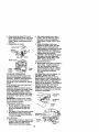
Owner's Manual
I(RRFT$1VlRH
°]
19.5 liP
ELECTRIC START
42" MOWER
AUTOMATIC
LAWN TRACTOR
Model No.
917.271823
•
•
•
•
•
Safety
Assembly
Operation
Maintenance
Repair Parts
CAUTION:
Read and follow all Safety
Rules and instructions before
operating this equipment.
For answers to your questions
about this product, Call:
1-800-659-5917
Sears Craftsman Help Line
5 am - 5 pro, Mort - Sat
Sears, Roebuck and Co., Hoffman Estates, II 60179
Visit our Craftsman website:www.sears.com/craffsman
Maintenance
Warranty
...............................................
2
....................................... 19
Service and Adjustments.................... 23
Storage ............................................... 29
Troubleshooting ................................. 30
Repair Parts ........................................ 34
Parts Ordering ..................... Back Cover
Safety Rules ......................................... 3
Product Specifications.......................... 6
Assembly .............................................. 8
Operation ............................................ 12
Maintenance Schedule ...................... 19
LIMITED TWO YEAR WARRANTY ON CRAFTSMAN RIDING EQUIPMENT PARTS
For two (2) years from the date of purchase, if this Craftsman Riding Equipment is
maintained, lubricated and tuned up according to the instructions in the owner's
manual, Sears will repair or replace, free of charge, any parts found to be defective in
matedal or workmanship. Warranty service is available free of charge by returning your
Craftsman dding equipment to your nearest Sears Service Center. In-home warranty
service is available but a tdp charge will apply. This warranty applies only while this
product is in the United States.
This Warranty does not cover:
• Expendable items which become worn during normal use, such as blades, spark
plugs, air cleaners, belts and oil filters.
• Tire replacement or repair caused by punctures from outside objects, such as nails,
thorns, stumps, or glass.
• Repairs necessary because of operator abuse, including but not limited to, damage
caused by towing objects beyond the capability of the ridingequipment, impacting
objects that bend the frame or crankshaft, or over speeding the engine.
• Repairs necessary because of operator negligence, including but not limited to,
electrical and mechanical damage caused by improper storage, failure to use the
proper grade and amount of engine oil, failure to keep the deck clear of flammable
debris, or the failure to maintain the equipment according to the instructions contained in the owner's manual,
• Engine (fuel system) cleaning or repairs caused by fuel determined to be contaminated or oxidized (stale). In general, fuel should be used within thirty (30) days of its
pumhese date.
• Riding equipment used for commemial or rental purposes. A product is "used for
commercial purpose" ff is used for any purpose other than single family household
dwellings or in usage where profit is made.
LIMITED 90 DAY WARRANTY ON BA'I-FERY
For ninety (90) days from date of purchase, if any battery included with this riding
equipment proves defective in material or workmanship and our testing determines the
battery will not hold a charge, Sears will replace the battery at no charge. Warranty
service is available free of charge by returning your Craftsman riding equipment to
your nearest Sears Service Center. In-home warranty service is available but a trip
charge will apply. This warranty applies only while this product is in the United States.
TO LOCATE THE NEAREST SEARS SERVICE CENTER OR TO SCHEDULE IN-HOME
WARRANTY SERVICE, SIMPLY CONTACT SEARS AT 1-800-4-MY-HOME
This Warranty gives you specific legal rights, and you may also have other dghts which
may vary from state to state.
Sears, Roebuck and Co., D/817 WA, Hoftman Estates, IL 60179
2
IMPORTANT: This cuttng mach nes capab e of amputating hands and feet and
throwing objects. Failure to observe the following safety instructionscould result in
sedous injury or death.
I. GENERAL OPERATION
I1. SLOPE OPERATION
• Read, understand, and follow all
Slopes are a major factor related to Iossinstructions in the manual and on the
ot-contro| and tipover accidents, which
machine before starting.
can result in severe injury or death. All
• Only allow responsible adults, who are
slopes require extra caution. It you
familiar with the instructions, to operate
cannot back up the slope or if you feel
the machine.
uneasy on it, do not maw it.
• Clear the area of objects such as rooks,
DO:
toys, wire, etc., which could be picked
• Mow up and down slopes, not across.
up and thrown by the blade.
• Remove obstacles such as rocks, tree
• Be sure the area is clear of other people
limbs, etc.
belore mowing. Stop manNne if anyone
Watch for holes, ruts, or bumps.
enters the area.
Uneven terrain could overturn the
• Never carry .pa_engers.
machine. Tall grass can hide obstacles.
• Do not mow in reverse unless absoUse slow speed. Choose a low gear
lutely necessary. Always look down and
so that you will not have to stop or shiff
behind before and while backing.
while on the slope.
• Be aware of the mower discharge
Follow the manufacturer's recommendirection and do not point it at anyone.
detians for wheel weights or counterDo not operate the mower without either
weights to improve stability.
the entire grass catcher or the guard in
Use extra care with grass catchers or
place.
other attachments. These can change
• Slow down before turning.
the stability of the machine.
• Never leave a running machine unatKeep all movement on the slopes slow
tended. Always turn off blades, set
and gradual. Do not make sudden
parking brake, stop engine, and remove
changes in speed or dirsctlen.
keys before dismounting.
Avoid staffing or stopping on a slope. It
• Turn off blades when not mowing.
tires lose traction, disengage the
• Stop engine before removing grass
blades and proceed slowly straight
catcher or unclogging chute.
down the slope.
• Mow only in daylight or good artificial
DO NOT;
light.
• Do not turn on slopes unless neces• Do not operate the machine while under
sary, and then, turn slowly and graduthe influence of alcohol or drUgs.
ally downhii|, if possible.
• Watch for traffic when operating near or
• Do not mow near dmp-offs, ditches, or
crossing roadways.
embankments. The mower could
• Use extra care when loading or unloadsuddenly turn over if a wheel is over
ing the machine into a trailer or truck.
the edge of a cliff or ditch, or if an edge
• Data indicates that operators, age 60
caves
In.
years and above, are involved in a large
• Do notmow on wet grass. Reduced
pementage of doing mower-related
traction could cause sliding.
injuries. These operatorS should
• Do not try to stabilize the machine by
evaluate their ability to operate the dding
putting your foot on the ground.
mower safely enough to protect them• Do notuse grass catcher on steep
selves and others from serious injury.
slopes.
• Keep machine free of grass, leaves or
other debris build-upwhich can touch
hot exhaust / engine parts and I_Jm. Do
not allew the mower deck to plow leaves
or other debris which can cause build-up
1ooccur. Clean any d_lor fuel
spillage before operating or stodng the
machine. Allow machine to cool before
storage.
Ill.CHILDREN
Tragic
accidents
canoccurif the operator
is not alert to the presence of children.
Children are often attracted to the
machine and the mowing activity. Never
assume that children will remain where
you last saw them.
• Keep children out of the mowing area
and under the watchful care of another
responsible adult.
• Be alert and turn machine off if children
enter the area.
• Before and when backing, look behind
and down for small children.
• Never carry children. They may fall off
and be seriously injured or interfere
with safe machine operation.
• Never allow children to operate the
machine.
• Use extra care when approaching blind
comers, shrubs, trees, or other objects
that may obscure vision.
IV. SERVICE
• Use extra care in handling gasoline
and other fuels. They are flammable
and vapors are explosive.
- Use only an approved container.
- Never remove gas cap or add fuel
with the engine running. Allow
engine to cool before refueling. Do
not smoke.
- Never refuel the machine indoors.
- Never store the machine or fuel
container inside where there is an
open flame, such as a water heater.
• Never run a machine inside a closed
area.
• Keep nuts and bolts, especially blade
attachment bolts, tight and keep
equipment in good condition.
• Never tamper with safety devices.
Check their proper operation regularly.
• Keep machine free of grass, leaves, or
other debris build-up. Clean oil or fuel
spillage. Allow machine to cool before
storing.
• Stop and inspect the equipment if you
strike an object. Repair, if necessary,
before restarting.
• Never make adjustments or repairs
with the engine running.
• Grass catcher components are subject
to wear, damage, and deterioration,
which could expose moving parts or
allow objects to be thrown. Frequently
check components and replace with
manufacturer's recommended parts,
when necessary.
• Mower blades are sharp and c_n cut.
Wrap the blede(s) or wear gloves, and
use extra caution when servicing them.
• Check brake operation frequently.
Adjust and service as required.
• Be sure the area is clear of other
people before mowing. Stop machine if
anyone enters the area.
• Never carry passengers or children
even with the blades off.
• Do not mow in reverse unless absolutely necessary. Always look down
and behind before and while becking.
• Never carry children. They may fall off
and be seriously injured or interfere
with safe machine operation.
• Keep children out of the mowing area
and under the watchful care of another
responsible adult.
4
• Be alert and turn machine off if children
enter the area.
• Before and when backing, look behind
and down for small children.
• Mow up and down slopes (15 ° Max),
not across.
• Remove obstacles such as rocks, tree
limbs, etc.
• Watch for holes, ruts, or bumps.
Uneven terrain could overturn the
machine. Tall grass san hide obstacles.
• Use slow speed. Choose a low gear so
that you will not have to stop or shift
while on the slope.
• Avoid starting or stopping on a slope. If
tires lose traction, disengage the
blades and proceed slowly straight
down the slope.
• If machine stops while going uphill,
disengage blades, shift into reverse
and back down slowly.
• Do not turn on slopes unless necessary, and then, tum slowly and gradually downhill, if possible.
_1_ CAUTION: Tow onlythe attachments
that are recommended by and comply
with specifications of the manufacturer of
your tractor. Use common sense when
towing. Operate only at the lowest
possible speed when on a slope. Too
heavy of a load, while on a slope, is
dangerous. Tires can lose traction with
the ground and cause you to lose control
of yourtractor.
_Look
for this symbol to point out
important safety precautions, if means
CAUTIONIII BECOMEALERTlll YOUR
SAFETY IS INVOLVED.
_,WARNING:
Engine exhaust, some of
its constituents, and certain vehicle
components contain or emit chemicals
known to the State of California to cause
cancer and birth defects or other reproductive harm.
_- CAUTION: in order to prevent
accidental starting when setting up,
transporting, adjusting or making repairs,
always disconnect spark plug wire and
place wire where if cannot contact spark
plug.
_=WARNING: Battery pests, terminals
and related accessories contain lead and
lead compounds, chemicals known to the
State of California to cause cancer and
birth defects or other reproductive harm.
Wash hands after handling.
CAUTION: Do not coast down a hill
in neutral, you may lose control of the
tractor.
PRODUCT SPECIFICATIONS
GASOLINE
CAPACITY
AND TYPE:
OILTYPE
API-SF-SJ):
DIL CAPACITY:
3PARK PLUG:
3AP: .030")
GROUND
SPEED (MPH):
TIRE
PRESSURE:
CHARGING
SYSTEM:
BA'FrERY:
BLADE BOLT
TORQUE:
3.5 GALLONS
UNLEADED
REGULAR
SAE 30
(ABOVE 32°F)
SAE 5W-30
(BELOW 32°F)
3.OPINTS
CHAMPION
RJ19LM OR J19LM
FORWARD: 5.5
REVERSE: 2.4
FRONT:
14 PSi
REAR:
10 PSI
3AM PS BA'I-I'ERY
5 AMPS HEADLIGHTS
AMP/HR:
30
MIN. CCA: 240
CASE SIZE:U1R
27-35 FT, LBS
CONGRATULATIONS on your purchase
of a new tractor. It has been designed,
engineered and manufactured to give
you the best possible dependability and
performance.
Should you expedence any problem you
cannot easily remedy, please contact a
Sears or other qualified service center.
We have competent, well-trained technicians and the proper tools to service or
repair this tractor.
Please read and retain this manual. The
instructions will enable you to assemble
and maintain your tractor properly.
Always observe the =SAFETY RULES".
REPAIR AGREEMENT
A Repair Agreement is available on this
product, Contact your nearest Sears
store for details.
CUSTOMER RESPONSIBILITIES
• Read and observe the safety roles.
• Follow a regular schedule in maintain*
ing, cadng for and using your tractor.
• Follow the instructionsunder "Maintenance" and "Storage" sections of this
owner's manual.
_I:_WARNING: This tractor is equipped
with an intemal combustion engine and
should not be used on or near any
unimproved forest-covered, brushcovered or grass-covered land unless the
engine's exhaust system is equipped with
a spark arrester meeting applicable local
or state laws (if any). If a spark arrester is
used, it should be maintained in effective
working order by the operator,
In the state of Calitomia the above is
required by law (Section 4442 of the
Calitomie Public Resources Code).
Other states may have similar laws.
Federal laws apply on federal lands. A
spark arrester for the muffler is available
through your nearest Sears service
center (See REPAIR PARTS section of
this manual),
6
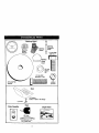
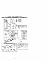
Steering Wheel
Steering
Sleeve
Steedng
Wheel
Adapter
Steedng
Extension
Shaft
(1) Hex Bolt
3/8-16 x 1
©
Insert
/
Wheel
(1) Lock I
washer •
3/8
(1) Hex Bolt
5/16-18 x 1-1/4
@
(1)
(1) LargeRat
Washer
Locknut
5/16-18
Seat
_tsher
17/32 x 1-3/16 x 12 Gauge
(1) Knob
Video Cassette
_
Keys
Slope Sheet
For Future Use
7
Your new tractor has been assembled at the factory with exception of those parts left
unassembled for shipping purposes. To ensure safe and proper operation of your
tractor all parts and hardware you assemble must be tightened securely. Use the
correct tools as necessary to insure proper tightness.
TOOLS REQUIRED FOR ASSEMBLY
A socket wrench set will make assembly
easier. Standard wrench sizes you need
are listed below.
(1) 9/16" wrench
(1) Pliers
(2) 1/2" wrench
(1) Utilityknife
(1) Tim pressure
drive ratchet gauge
When dght or left hand is mentioned in
this manual, if means when you are in the
operating position (seated behind the
steering wheel).
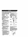
7. Snap steering wheel insert into center
of steering wheel.
8. Remove protective mataitals from
tractor hood and grill.
IMPORTANT: Check for and remove any
staples in skid that may puncture tire
where tractor is to roll off skid.
__
_
Steedng
_
Wheel Insert
FlexBolt
_::_
L_k Washer
F'/'_,_I
_
_ Large Flat
TO REMOVE TRACTOR FROM
CARTON
UNPACK CARTON
1. Remove all accessible loose parts
and parts cartons from carton.
2. Cut, from top to bottom, along lines on
all four comers of carton, and lay
panels flat.
3. Check for any additional loose parts
or cartons and remove.
Steedng_
_
5/16 Lockn__
BEFORE REMOVING TRACTOR
FROM SKID
ATFACHSTEERING WHEEL
ASSEMBLE EXTENSION SHAFT AND
BOOT
1. Slide extension shaft onto lower
steedng shaft. Align mounting holes
in extension and lower shafts and
install 5/16 hex bolt and Iocknut.
Tighten securely.
IMPORTANT: Tighten bolt and nut
securelyto 19-22 ft. Ibs torque.
2. Place tabs of steering boot over tab
slots in dash and push down to
secure.
iNSTALL STEERING WHEEL
3. Positionfront wheels of the tractor so
they are pointing straight forward.
4. Remove steedng wheel adapter from
steedng wheel and slide adapter onto
steering shaft extension.
5. Position steedng wheel so cross bars
are horizontal (left to dght) and slide
inside boot and onto adapter.
6. Assemble large flat washer, 3/8 lock
washer, 3/8 hex bolt and tighten
securely.
Washer
Sleedng Boot
5/16 Hex Bolt
Lowersteering_
_i
Shaft
,_"-_. _
Tab
Slot
HOWTO SET UPYOUR TRACTOR
CHECK BATTERY
1. Lift hood to raised position.
NOTE: If this battery is put into service
after month and year indicated on label
(label located between terminals) charge
battery for minimum of one hour at 6-10
amps. (See =BA'I-I'ERY"in Maintenance
section of this manual for charging
instructions).
_=_.=_-.'....--:_-_
8
Label
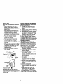
INSTALL
SEAT
TO ROLL TRACTOR OFF SKID (See
Adjustseatbefore
tightening
adjustmentOperation section for location and
knob.
function of controls)
1. Remove
adjustment
knobandfiat
Press lift lever plunger and raise
washer
securing
seattocardboard 1, attachment
llft lever to its highest
packing
andsetasidefor assembly of
position.
seat to tractor.
2. Pivot seat upward and remove from
the cardboard packing. Remove the
cardboard packing and discard.
3. Place seat on seat pan so head of
shoulder boll is positioned over large
slotted hole in pan.
4. Push down on seat to engage
shoulder bolt in slot and pull seat
towards rear of tractor.
5. Pivot seat and pan forward and
assemble adjustment knob and flat
washer loosely. Do not tighten.
6. Lower seat into operating position and
sit in seat.
7. Slide seat until a comfortable position
is reached which allows you to press
clutch/breke pedal all the way down.
8. Get off seat without moving its
adjusted position.
9. Raise seat and tighten adjustment
knob securely.
Seat Pan_ulder
FlatWas
h__
NOTE: You may now roll or ddve your
tractor off the skid. Followthe appropriate
instructionbelow to remove the tractor
from the skid.
2. Release parking brake by depressing
clutch/brake pedal.
3. Place freewheel control in freewheeling position to disengage transmission (See "TO TRANSPORT" in the
Operation section of this manual).
4. Roll tractor forward off skid.
5. Remove banding holding deflector
shield up against tractor.
TO DRIVE TRACTOR OFF SKID (See
Operation section for location and
function of controls)
_I=WARNING: Before starting, read,
understand and follow all instructions in
the Operation section of this manual. Be
sure tractor is in a welI-ventitated area.
Be sure the area in front of tractor is
clear of other people and objects.
1. Be sure all the above assembly steps
have been completed.
2. Check engine oil level and fill fuel
tank with gasoline.
3. Place freewheel control in "transmission engaged" position.
4. Sit on seat in operating position,
depress clutch/brake pedal and sat
the parking brake.
5. Place motion control lever in neutral
(N) position.
6. Press lift lever plunger end raise
attachment lift lever to its highest
position.
7. Start the engine. After engine has
started, move throttle control to idle
position.
8. Release paddng brake.
9. Slowly move the motion control lever
forward and slowly drive tractor off
skid.
10.Apply brake to stop tractor, set
parking brake and place motion
control lever in neutral position.
11 .Turn ignitionkay to =OFF_position.
Continue with the instructionsthat follow.
9
CHECK TIRE PRESSURE
The tires on your tractor were overinflated
at the factory for shipping purposes.
Correct tire pressure is important for best
cutting performance.
• Reduce tire pressure to PSi shown in
=PRODUCT SPECIFICATIONS" section
of this manual
CHECK DECK LEVELNESS
For best cutting results, mower housing
should be properly leveled. See "TO
LEVEL MOWER HOUSING" in the
Service and Adjustments section of this
manual.
CHECK FOR PROPER POSITION OF
ALL BELTS
See the figures that are shown for
replacing motion and mower blade ddve
belts in the Service and Adjustments
section of this manual, Verify that the
belts are routed correctly,
CHECK BRAKE SYSTEM
After you learn how to operate your
tractor, check to see that the brake is
propady adjusted. See "TO ADJUST
BRAKE" in the Service and Adjustments
section of this manual,
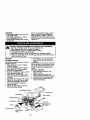
INSTALL MULCHER
PLATE
(If previously removed)
1. Raise and hold deflector shield in
upright position.
2. Place front of roulcher plate over front
of mower deck opening and slide into
place, as shown.
3. Hook front latch into hole on front of
mower deck.
4. Hook rear latch into hole on back of
mower deck.
CAUTION: Do not remove deflector
shield from mower. Raise and hold shield
when attaching muioher plate and allow it
to rest on plate while in operation.
Deflector
Mulcher
Plate
Hooks
TO CONVERTTO BAGGING OR
DISCHARGING
Simply remove mulcher plate and store in
a safe place. Your mower is now ready for
discharging or installation of optional
grass catcher accessory.
NOTE: It is not necessary to change
blades. The mulcher blades are designed for discharging and bagging also.
10
I/CHECKLIST
BEFORE YOU OPERATE AND ENJOY
YOUR NEW TRACTOR, WE WISH TO
ASSURE THAT YOU RECEIVE THE BEST
PERFORMANCE AND SATISFACTION
FROM THIS QUALITY PRODUCT.
PLEASE REVIEWTHE FOLLOWING
CHECKLIST:
,/ All assembly instructions have been
completed.
,/No remaining loose parts in carton.
,/Battery is proporly prepared and
charged. (Minimum 1 hour at 6 amps).
,/Seat is adjusted comfortably and
tightened securely.
•/ All tires are propedy inflated. (For
shipping purposes, the tires were
ovednltated at the factory).
,/Be sure mower deck is properly leveled
side-to-side/frent-to-rear for best cutting
results. (Tires must be propedy inflated
for leveling).
,I Check mower and drive belts. Be sure
they are routed properly around pulleys
and inside all belt keepers.
,! Check wiring. See that all connections
are still secure and wires are properly
clamped.
J Before driving tractor, be sure freewheel control is in drive position.
WHILE LEARNING HOWTO USE YOUR
TRACTOR, PAYEXTRAA'I-rENTION TO
THE FOLLOWING IMPORTANT ITEMS:
,/Engine oil is at proper level.
,/Fuel tank is filled with fresh, clean,
regular unleaded gasoline.
J" Become familiar with all controls - their
location and function. Operate them
before you start the engine.
J Be sure brake system is in safe
operating condition.
,/" It is important to purge the transmission
before operating your tractor for the first
time. Follow proper starting and
transmission purging instructions (See
"TO START ENGINE _and =PURGE
TRANSMISSION" in the Operation
section of this manual).
11
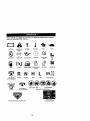
These symbols may appear on your tractor or in literature supplied with the product.
Learn and understand their meaning.
BA'FrERY
CAUTION OR
WARNING
REVERSE
ENGINE ON
ENGINE OFF
OIL PRESSURE
FUEL
CHOKE
ATFACHMENT
CLUTCH ENGAGED
REVERSE
FORWARD
MOWER HEIGHT
NEUTRAL
SLOW
LIGHTS ON
OVER TEMP
LtGHT
PARKING BRAKE
LOCKED
UNLOCKED
H
L
HIGH
LOW
KEEP AREA CLEAR
IGNITION
FAST
ATFACHMENT
CLUTCH DISENGAGED
MOWER
LIFT
PARKING BRAKE
SLOPE HAZARDS
(SEE SAFETY RULES SECTION)
FREEWHEEL
(Automatic Modelsonly)
DANGER, KEEP HANDS AND FEET AWAY
12
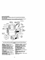
KNOWYOUR TRACTOR
READ THIS OWNER'S MANUAL AND SAFETY RULES BEFORE OPERATING
YOUR TRACTOR
Compare the illustrationswith your tractor to familiadze yourself with the locations of
vadous controls and adjustments. Save this manual for future reference.
"it Switch
Attachment
Clutch Lever
Ignilion
Switch
Ammeter
Lever
Choke Contro_x
PILmger
Throttle Control-.....
Lift Lever
Clutch/
Brake Pedal
Height
Adjustment
Indicator
Free Wheel
Control
Brake Lever
Motion
:ontml
Lever
Ourtractorsconformto the safetystandardsof theAmedcanNationalStandards
Institute.
AMMETER - Indicates charging (+) or
discharging (-) of battery.
A'I'FACHMENT CLUTCH LEVER - Used
to engage the mower blades, or other
attachments mounted to your tractor.
ATTACHMENT LIFT LEVER. Used to
raise, lower, and adjust the mower deck
or other attachments mounted to your
tractor.
CHOKE CONTROL - Used when starting
a cold engine.
CLUTCH/BRAKE PEDAL - Used for
declutching and braking the tractor and
starting the engine.
MOTION CONTROL LEVER - Selects the
speed and direction of tractor.
FREEWHEEL CONTROL - Disengages
transmission for pushing or slowly
towing the tractor with the engine off.
IGNDON SWITCH - Used for starting
and stopping the engine.
LIFT LEVER PLUNGER - Used to
release attachment lift lever when
changing its position.
LIGHT SWITCH - Turns the headlights on
and off.
PARKING BRAKE LEVER - Locks
clutch/brake pedal into the brake
position.
THRO'I-rLE CONTROL- Usedto control
engine speed.
13
The operation of any tractor can result in foreign objects thrown intothe
eyes, which con result in severe eye damage. Always wear safety
glasses or eye shields while operating your tractor or performing any
adjustments or repairs. We recommend a wide vision safety mask over
spectacles or standard safety glasses.
HOW TO USE YOUR TRACTOR
TO SET PARKING BRAKE
• Never use choke to stop engine.
IMPORTANT: Leaving the ignition switch
in any position other than "OFF" will
Your tractor is equipped with an operator
cause the battery to be discharged,
presence sensing switch. When engine
(dead).
is running, any attempt by the operator to
NOTE: Under certain conditionswhen
leave the seat withoutfirst settingthe
tractor is standing idle with the engine
parking brake will shut off the engine.
running, hot engine exhaust gases may
1. Depress clutch/brake pedal into full
cause "browning"of grass. To eliminate
"BRAKE" position and hold.
this possibility,always stop engine when
2. Place parking brake lever in =ENstopping tractor on grass areas.
GAGED" position and release
_CAUTION:
Always stop tractor
pressure from clutch/brake pedal.
Pedal should remain in "BRAKE"
completely, as descdbed above, before
leaving the operator's position;to empty
position. Make sure parking brake
will hold tractor secure.
grass catcher, etc.
TO
USE TH ROTTLE CONTROL
Attachment
C
lutchLever
Choke
Always operate engine at full throttle.
Control_,
%
• Operating engine at less than full
IgnitionKey
throttle reduces the battery charging
Control
rate.
_=Disengaged"
Thmttle_
Position
Engaged"
Position • Full throttle offers the best bagging and
Clutch/__,
mower performance.
Brake
MotionControl
TO USE CHOKE CONTROL
Usa choke control whenever you are
startinga cold engine. Do not use to start
a warm engine.
"Brake"
"Engaged"
=Disengaged"
• To engage choke control, pull knob
Position
Position Position
out. Slowly push knob in to disengage.
STOPPING
TO MOVE FORWARD AND BACKWARD
MOWER BLADES The direction and speed of movement is
• To stop mower blades,move attachcontrolled by the motion control lever.
ment clutch lever to "DISENGAGED"
1. Start tractor with motion control lever in
position.
neutral (N) position.
GROUND DRIVE.
2. Release parking brake and clutch/
brake pedal.
• To stop ground drive, depress clutch/
3. Slowly move motion control lever to
brake pedal into full "BRAKE" position.
• Move motion control laver to neutral (N)
desired position.
position.
TO ADJUST MOWER cU'nlNG HEIGHT
IMPORTANT: The motion control lever
The position of the attachment lift lever
does not return to neutral (N) position
determines the cuffing height.
when the clutch/brake pedal is de• Grasp lift lever.
pressed.
• Press plunger with thumb and move
ENGINE.
lever to desired position.
• Move throttle control to slow position.
The
cutting height range is approxiNOTE: Failure to move throttle control to
mately 1-1/2 to 4". The heights are
slow position and allowing engine to idle
measured from the ground to the blade
=beforestopping may cause engine to
tip with the engine not running.
backfire".
• Turn ignition key to "OFF" position and
remove key. Always remove key when
leaving tractor to prevent unauthorized
use.
14
TO STOP MOWER BLADES disengage attachment clutch control.
_,CAUTION:
Do not operate the mower
without either the entire grass catcher, on
mowers so equipped, or the deflector
shield in place.
AttachmentClutchLever
=Engaged"Position
J
_ Attachen_tLitt
(( _J!_
Lever High
/_' Position
These heights are approximate and may
vary depending upon soil conditions,
height of grass and typos of grass being
mowed.
• The average lawn should be cut to
approximately 2-1/2 inches during the
cool season and to over 3 inches
dudng hot months. For healthier and
better looking lawns, mow often and
after moderate gmwth.
• For best cutting performance, grass
over 6 inches in height should be
mowed twice. Make the first cut
relatively high; the second to desired
height.
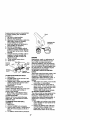
TO ADJUST GAUGE WHEELS
Gauge wheels are pmpody adjusted
when they are slightly off the ground
when mower is at the desired cutting
height in operating position. Gauge
wheels then keep the deck in proper
position to help prevent scalping in most
terrain conditions.
NOTE: Adjust gauge wheels with tractor
on a flat level surface.
1. Adjust mower to desired cutting height
(See "TO ADJUST MOWER CU'I-FING
HEIGHT in the Operation section of
this manual).
2. With mower in desired height of cut
position, gauge wheals should be
assembled so they are slightly off the
ground. Install gauge wheel in
apprepdate hole with shoulder belt,
3/8 washer, and 3/8-16 Iooknut and
tighten securely.
3. Repeat for opposite side installing
gauge wheel in same adjustment
hole.
3/8-16
_
TO OPERATE ON HILLS
4qLCAUTION: Do not drive up or down
hills with slopes greater than 15° and do
not ddve across any slope.
• Choose the slowest speed before
starting up or down hills.
• Avoid stopping or changing speed on
hills.
• If slowing is necessary, move throttle
control lever to slower position.
• If stopping is absolutely necessary,
push clutch/brake pedal quickJyto
brake position and engage parking
brake.
• Move motion control lever to neutral
(N) position.
IMPORTANT: The motion control lever
does not return to neutral (N) position
when the clutch/brake pedal is depressed.
• To restart movement, slowly release
parking brake and clutch/brake pedal.
• Slowly move motion control lever to
slowest setting.
• Make all turns slowly.
._"
Loc nu,\.(
W e,
Gauge
Mounting
_t_l" _(==::_
Bracket--_---------_.Y= _
3/8 Washer --'="_"_"p-)_
Gauge Wheel_*_/
'
;
TO TRANSPORT
;houfder
Boll
When pushing or towing your tractor, be
sure to disengage transmission by
placing freewheel control in freewheeling
position. Free wheel control is located at
the rear drawbar of tractor.
1. Raise attachment lift to highest
position with attachment lift control.
2. Poll freewheel control out and down
into the slot and release so it is held in
the disengaged position.
TO OPERATE MOWER
Your tractor is equipped with an operator
presence sensing switch. Any attempt by
the operator to leave the seat with the
engine running and the attachment
clutch engaged will shut off the engine.
1. Select desired height of cut.
2. Start mower blades by engaging
attachment clutch control.
15
• Do not push or tow tractor at more than
two (2) MPH.
• To reengage transmission, reverse
above procedure.
NOTE: To protect hood from damage
when transporting your tractor on a truck
or a trailer, be sure hood is closed and
secured to tractor. Use an appropriate
means of tying hood to tractor (rope, cord,
etc.).
IMPORTANT: When operating in
temperatures below 32°F(0°C), use fresh,
clean winter grade gasoline to help
insure good cold weather starting.
AWARNING:
Experience indicates that
alcohol blended fuels (called gasohol or
using ethanol or methanol) can attract
moisture which leads to separation and
formation of acids during storage. Acidic
gas can damage the fuel system of an
engine while in storage. To avoid engine
problems, the fuel system should be
emptied before storage of 30 days or
Iong.er. Drain the gas tank, start the
engine and let it run until the fuel lines
and carburetor are empty. Use fresh fuel
next season. See Storage Instructionsfor
additional information. Never use engine
or carburetor cleaner products in the fuel
_nk or permanent damage may occur.
CAUTION: Fillto bottom of gas tank
filler neck. Do not overfill. Wipe offany
spilled oil or fuel. Do not store, spill or
use gasoline near an open flame.
TOWING CARTS AND OTHER
A'FrACHMENTS
Tow only the attachmants that are
recommended by and comply with
specifications of the manufacturer of your
tractor. Use common sense when towing.
Too heavy of a load, while on a slope, is
dangerous. "Rrescan lose traction with
the ground and cause you to lose control
of yourtractor.
TO START ENGINE
When staring the er_ne forthe first_me or if
the angine hss mn out offuel,it wil take
extra crankingtime to movefuel from1he
tankto the engine.
1. Be sure freewheel control is in the
transmission engaged position.
2. Sit on seat in operating position,
depress clutchJbrakepedal and set
parking brake.
3. Place motion control lever in neutral
(N) position.
4. Move attachment clutchto "DISENGAGED" position.
5. Move throttle control to fast position
6. Pull choke control out for a cold
engine start attempt. For a warm
engine start attempt the choke control
may not he needed.
NOTE: BeforestaC,
Jng,readthe warm and
coldstaring proosdarssbelow.
7. Insert key into ignition and turn key
clockwise to =START" position and
release key as soon as engine starts.
Do not run starter continuouslyfor
more than fifteen seconds per minute.
If the engine does not start after
several attempts, push choke control
in, wait a few minutes and try again. If
engine still does not start, pull the
choke control out and retry.
BEFORE STARTING THE ENGINE
CHECK ENGINE OIL LEVEL
The engine in your tractor has been
shipped, from the factory, already filled
with summer weigh oil.
1. Check engine oil with tractor on level
ground.
2. Remove oil fill cap/dipstick and wipe
clean, reinsert the dipstick and screw
cap tight, waif for a few seconds,
remove and read oil level. If necessary, add oil until "FULL" mark on
dipstick is reached. Do not overfill.
• For cold weather operaiton you should
change oil for easier starting (See "OIL
VISCOSITY CHART" in the Maintenance section of this manual).
• To change engine oil, see the Maintenance section in this manual.
ADD GASOLINE
• Fill fuel tank. Use fresh, clean, regular
unleaded gasoline with a minimum of
87 octane. (Use of leaded gasoline
will increase carbon and lead oxide
deposits and reduce valve life). Do not
mix oil with gasoline. Purchase fuel in
quantities that can be used within 30
days to assure fuel freshness.
16
WARM WEATHER STARTING (50° Fend
above)
8. When engine starts, slowly push
choke control in until the engine
begins to run smoothly. If the engine
starts to run roughly, pull the choke
control out slightly for a few seconds
and then continue to push the control
in slowly.
• The attashrnents end gmond ditve cen
now he used. If the enginedcos not accept
the Icad, restart the engineend allow it to
warm up for one minuteusing the choke
as _
abova.
PURGE TRANSMISSION
_kCAUTION: Never engage or disengage
freewheel lever while the engine is
running.
To ensure proper operation and pedormanse, If is recommended that the
transmissionbe purged before operating
tractorfor the first time. This procedure will
remove any trapped air inside the trans.
mission which may have developed during
shippingof your tractor.
IMPORTANT: Should your transmission
require removal for service or replacement,
it should be purged after reinstallation
before operatingthe tractor.
1. Place tractor safely on level surface
with engine oft and parking brake set.
2. Disengage transmission by placing
freewheel control in freewheeling
position (See "TO TRANSPORT" in
this section of manual).
3. Sitting in the tractor seat, start engine.
After the engine is running, move
throttle control to slow position. With
motion control lever in neutral (N)
position, slowly disengage clutch/
brake pedal.
4. Move motion control lever to full
forward position and hold for five (5)
seconds. Move lever to full reverse
position and hold for five (5) seconds.
Repeat this procedure three (3) times.
NOTE: During this procedure there will be
no movement of drive wheels. The air is
being removed from hydraulicdrive
system.
5. Move motion control lever to neutral
(N) position. Shut- off engine and set
parking brake.
6. Engage transmission by plecin_
freewheel control in driving position
(See "TO TRANSPORT" in this section
of manual).
7. Sitting in the tractor seat, start engine.
After the engine is running, move
throttle control to half (1/2) speed. With
motion control lever in neutral (N)
position, slowly disengage clutch/
brake pedal.
8. Slowly move motion control lever
forward, after the tractor moves
approximately five (5) feet, slowly
move motion control lever to reverse
position. After the tractor moves
approximately five (5) feet return the
motion control lever to the neutral (N)
position. Repeat this procedure with
the motion control lever three (3)
times.
Your tractor is now purged and now ready
for normal operation.
COLD WEATHER STARTING (50° F and
below)
8. When engine starts, slowly push
choke control in until the engine
begins to run smoothly. Continue to
push the choke control in smell steps
allowing the engine to accept small
changes in speed and load, until the
choke control is fully in. If the engine
starts to run roughly, pull the choke
control out slightly for a few seconds
and then continue to push the control
in slowly. This may require an engine
warm-up period from several seconds
to several minutes, depending on the
temperature.
AUTOMATICTRANSMISSION WARM UP
Before driving the unit in cold weather,
the transmission should be warmed up as
follows:
1. Be sure the tractor is on level ground.
2. Place the motion control lever in
neutral. Release the parking brake
and let the clutclVbrake slowly return
to operating position.
3. Allow one minute for transmission to
warm up. This can be done during the
engine warm up period.
• The attachments can be used during
the engine warm-up period after the
transmission has been warmed up and
may require the choke control be
pulled out slightly.
NOTE: If at a high altitude (above 3000
feet) or in cold temperatures (below 32 F)
the carburetor fuel mixture may need to
be adjusted for best engine performance.
See =TO ADJUST CARBURETOR" in the
Service and Adjustments section of this
manual.
17
MOWING
TIPS
• Mower
should
bepropedy
leveled
for
bestmewing
performance.
See"TO
LEVEL
MOWER
HOUSING"
inthe
Service
andAdjustments
section
ofthis
manual.
• Thelefthandsideofmower
should
be
usedfor tdmming.
• Drive so that clippings are discharged
onto the area that has been cut. Have
the cut area to the right of the tractor.
This will result in a more even distribution of clippings and more uniform
cutting.
• When mowing large areas, start by
turning to the dght so that clippings will
discharge away from shrubs, fences,
ddveways, etc. After one or two
rounds, mow in the opposite direction
making left hand turns until finished.
• If grass is extremely tall, it should be
mowed twice to reduce load and
possiblefire hazard from dded clippings. Make first cut relatively high; the
second to the desired height•
• Do not mow grass when it is wet. Wet
grass will plug mower and leave
undesirable clumps. Allow grass to dry
before mowing.
• Always operate engine at full throttle
when mowing to assure better mowing
performance and proper discharge of
material. Regulate ground speed by
selecting a low enough gear to give the
mower cutting performance as well as
the quality of cut desired.
• When operating attachments, select a
ground speed that will suit the terrain
and give best performance of the
attachment being used.
MULCHING
MOWING TIPS
IMPORTANT: For best performance,
keep mower housing free of built-up
grass and trash. Clean after each use.
• The special mulching blade will recut
the grass clippings many times and
reduce them in size so that as they fall
onto the lawn they will disperse into the
grass and not be noticed. Also, the
mulched grass will biodegrade quickly
to provide nutdents for the lawn.
Always mulch with your highest engine
(blade) speed as this will provide the
best recuttlngaction of the blades.
• Avoid cutting your lawn when it is wet.
Wet grass tends to form clumps and
interferes with the mulching action.
The best time to mow your lawn is the
eedy afternoon. At this time the grass
has dded and the newly cut area will
not be exposed to the direct sun.
• For best results, adjust the mower
cutting height so that the mower cuts off
only the top one-third of the grass
blades. For extremely heavy mulching,
reduce your width of cut on each pass
and mow slowly.
• Certain types of grass and grass
conditions may require that an area be
mulched a second time to completely
hide the clippings. When doing a
second cut, mow across or perpendicular to the first cut path.
• Change your cutting pattern from week
to week. Mew north to south one week
then change to east to west the next
week. This will help prevent matting
and graining of the lawn.
18
CBeckOperatorP_ce
and
T interlock
Symm=
tf
R
_
Cl_edl for Loose Fastmlem
cA Sha_lv_eplace
oT ch_
Mower Bled_
BetmryLav_
I_T
V'
I_4
I_
CBec_ Tmrr=axkl Cooling
AdjustBledJBelt(s)T_Ioe
AdjustMom_ _
E
/'_
changeEngln_ON
_/_:
CleanAir Fll_r
_
N Clean
Nr Scn_e_
GI
I_
Belt(=)Tension
Insp_
t/
_=
MuffkwSp_ rk ArmOur
ReplaceOI Fbr (If equipped)
_.=
Replace AI_ Fbr Paper Cactfld_e
I1_
Replacs Fuel Flier
GENERAL
I_
LUBRICATION CHART
RECOMMENDATIONS
_) Spindle_
The warranty on thistractordoes not cover
items that have been subjected to operator
abuse or negligence. To receive full value
from the warranty, operator must maintain
tractoras instructedin this manual.
Some adjustments will need to be made
pedndiually to properly maintain your
tractor.
All adjustments in the Service and
AdjustmentssectJonof this manual should
be checked at least once each season.
• Once a year yon should replace the
spark plug, clean or replace air filter, and
check blades and belts for wear. A new
spark plug and clean air filter assure
proper air-fust mixture and help your
engine mn better end lostlonger,
BEFORE EACH USE
1. Check engine oil level.
2. Check brake operation.
3, Check tire pressure.
4, Check operator presence and
interlock systems for proper operation.
5. Check for loose fasteners.
('_---'--'-_'_ _
e;11
_Fmnt Wheel_-_/
Bz_ing
._,_ ......
{_Spindle
Zor
_--_Fmht Wheel
] :,._BeedngZerk
............
_)Goneral Purpose Grease
_)Refer to Maintenance"Engine"Section
IMPORTANT: Do not oil or grease the
pivot points which have special nylon
beadngs. Viscous lubricants will attract
dust and dirt that will shorten the life of
the seff-lubricetin_]beadngs, If you feel
they must be lubneated, use only a d_,,
powdered graphite type lubrisent
sparingly.
19
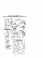
TRACTOR
4. Reassemble hex bolt, lock washer
and flat washer in exact order as
Always observe safety rules when
shown.
performing any maintenance.
5.
Tighten belt securely (27-35 Ft. Lbs.
BRAKE OPERATION
torque).
If tractor requires more than six (6) feet
IMPORTANT: Blade bolt is grade 8 heat
stopping distance at high speed in
treated.
MandrelAssembly
highest gear, then brake must be adEdgeUp
justed. (See "TO ADJUST BRAKE" in the
Blade Center
Hole
Service and Adjustments section of this
manual).
Flat Washer.
TIRES
LockWashe
• Maintain proper air pressure in all tires
(See =PRODUCT SPECIFICATIONS"
section of this manual).
• Keep tires free of gasoline, oil, or insect
control chemicals which can harm
bysix lineson the bolthead.
rubber.
TO SHARPEN BLADE
• Avoid stumps, stones, deep ruts, sharp
NOTE: We do not recommend sharpenobjects and other hazards that may
ing blade - but if you do, be sure the
cause tire damage.
blade is balanced.
NOTE: To seal tire punctures and prevent
Care should be taken to keep the blade
flat tires due to slow leaks, tire sealant
balanced. An unbalanced blade will
may be purchased from your local parts
cause excessive vibration and eventual
dealer. Tire sealant also prevents tire dry
damage to mower and engine.
rot and corrosion.
• The blade can be sharpened with a file
OPERATOR PRESENCE SYSTEM
or on a gdndlng wheel. Do not attempt
Be sure operator presence and interlock
to
sharpen while on the mower.
systems are working properly. If your
• To check blade balance, you will need
tractor does not function as described,
a 5/8" diameter steel belt, pin, or a cone
repair the problem immediately.
balancer. (When using a cone bal• The engine should not start unless the
ancer, follow the instructionssupplied
brake pedal is fully depressed and
with balanoer.)
attachement clutch control is in the
NOTE: Do not use a nail for balancing
disengaged position.
blade. The lobes of the center hole may
• When the engine is running, any
appear to be centered, but are not.
attempt by the operator to leave the
• Slide blade on to an unthraaded
seat without first setting the parking
portion of the steel bolt or pin and hold
brake should shut off the engine.
• When the engine is running and the
the bolt or pin parallel with the ground.
If blade is balanced, it should remain in
attachment clutch is engaged, any
attempt by the operator to leave the
a horizontal position. If either end of
seat should shut off the engine.
the blade moves downward, sharpen
• The attachment clutch should never
the heavy end until the blade is
balanced.
operate unless the operator is in the
seat.
Center Hole
BLADE CARE
For best results mower blades must be
5/_
kept sharp. Replace bent or damaged
blades.
BLADE REMOVAL
1. Raise mower to highest position to
BAITERY
allow access to blades.
Your tractor has a battery charging system
2. Remove hex bolt, lock washer and flat
which is sufficient for normal use. Howwasher sscuring blade.
ever, pedodic charging of the battery with
3. Install new or resharpened blade with
an automotive charger will extend its life.
trailing edge up towards deck as
• Keep battery and terminals clean.
shown.
• Keep battery bolts tight,
IMPORTANT: To ensure proper assembly
• Keep small vent holes open.
center hole in blade must akgn with star
• Recharge at 6-10 amperes for 1 hour.
on mandrel assembly.
2O
NOTE: The original equipment battery on
your tractor is maintenance free. Do not
attempt to open or remove caps or covers.
Adding or checking level of electrolyte is
not necessary.
NOTE: Although multi-viscosity oils
TO CLEAN BA'I-I'ERY AND TERMINALS
(5W30, 10W30 etc.) improve starting in
Corrosion and dirt on the batten/and
cold weather, these multi-viscosityoils
terminals can cause the battery to "leak"
will result in increased oil consumption
power.
when used above 32°F. Check your
1. Remove terminal guard.
engine oil level more frequently to avoid
2. Disconnect BLACK battery cable first
possible engine damage from mnoing
then RED battery cable and remove
low on oil.
battery from tractor.
Change the oil after every 25 hours of
3. Rinse the battery with plain water and
operation or at least once a year if the
dry.
tractor Is not used for 25 hours in one
4, Clean terminals and battery sable
year.
ends with wire brush until bright.
Chock the crankcase oil level before
5. Coat terminals with grease or petrostarting the engine and attar each eight
leum jelly.
(8) hours of operation. _ghten oil fill cap/
6. Reinstall battery (See =REPLACING
dipsticksecurely each time you check the
BATTERY" in the SERVICE AND
oil level.
ADJUSTMENTS section of this
TO
CHANGE ENGINE OIL
manual).
V-BELTS
Determine temperature range expected
before oil change. Ag oil must meet API
Check V-belts for deterioration and wear
service classification SF-SJ.
after 100 hours of operation and replace
• Be sure tractor is on level surface.
if necessary.The belts are not adjustable.
• Oil will drain more freely when warm.
Replace belts if they begin to slip from
wear.
• Catch oil in a suitable container,
TRANSAXLE COOLING
1. Remove oil fill cap/dipstick, Be careful
The transmission fan and cooling fins
not to allow dirt to enter the engine
should be kept clean to assure proper
when changing oil,
cooling.
2. Remove cap from end of drain valve
Do not attempt to clean fan or transmisand install the drain tube onto the
fitting.
sion while engine is running or while the
transmission is hot. To prevent possible
3, Unlock drain valve by pushing inward
damage to seals, do oct use high
slightly end turning counterclockwise.
pressure water or steam to clean
4. To open, pull out on the drain valve.
transaxle.
5. After oil has drained completely, close
• Inspect coolingfan to be sure fan
and lock the drain valve by pushing
blades are intact and clean.
inward and turning clockwise until the
pin is in the locked position as shown.
• Inspect cooling fins for dirt, grass
clippings and other materials. To
6. Remove the drain tube and replace
prevent damage to seals, do not use
the cap onto to the end of the drain
valve.
compressed air or high pressure
sprayer to clean cooling fins.
7. Refill engine with oil through oil fill
TRANSAXLE PUMP FLUID
dipsticktube. Pour slowly. Donot
overfill. For approximate capacity see
The trensaxle was sealed at the factory
"PRODUCT SPECIFICATIONS"
and fluid maintenance is not required for
the life of the transaxle. Should the
section of this manual.
8. Use gauge on oil fill cap/dipstick for
transaxle ever leak or require servicing,
contact your nearest authorized service
chocking level. Be sure dipstickcap is
center/department.
tightened securely for accurate
ENGINE
reading. Keep oil at "FULL" line on
dipstick.
LUBRICATION
Only use high quality detergent oil rated
with API service classificationSF-SJ.
Select the oil's SAE viscositygrade
according to your expected operating
temperature.
21
Oil Drain VaJve
Closed and
Position
Drain
ube
Cap _T
Locked
CLEAN AIR SCREEN
Air screen must be kept free of dirt and
chaff to prevent engine damage from
overheating. Clean with a wire brush or
compressed air to remove dirt and
stubbem dded gum fibers.
ENGINE COOLING FINS
Remove any dust, dirt or eil from engine
cooling fins to prevent engine damage
from overheating. Air guide covers must
be removed. Remove side panels and
hood (See "TO REMOVE HOOD AND
GRILL ASSEMBLY" in the Service and
Adjustments section of this manual).
Top Air
GuideCover_-,
Engine
,^,__
_
Cooling F_
Air Guide
__
Cover
cBoS,d
\\\
-
AIR FILTER
Your engine will not run properly using a
dirtyair filter. Clean the foam pre-cleaner
after every 25 hoursof operation or every
season. Service paper cartridge every 100
hours of operation or every season,
whichever occurs first.
Service air cleaner more often under dusty
conditions.
1. Remove knob(s) and cover.
TO SERVICE PRE-CLEANER
2. Slide foam pre-cleaner off cartridge.
3. Wash it in liquid detergent and water.
4. Squeeze it dry in a clean cloth.
5. Saturate it in engine oil. Wrap it in
clean, absorbent cloth and squeeze to
remove excess oil.
NOTE; If very dirty or damaged, replace
pre-cleaner.
6. Reinstall pre-cleaner over cartridge.
7. Reinstall cover and secure with
knob(s).
TO SERVICE CARTRIDGE
1. Remove wing nuts and cartridge
plate.
_p
2. Carefully remove cartridge to prevent
debds from entering carburetor.
3. Clean cartridge by tapping gently on
flat surface.
NOTE: If very dirty or damaged, replace
cartridge.
4. Reinstall cartddge plate, wing nuts,
precleaner, cover and secure with
knob(s).
IMPORTANT= Petroleum solvents, such
as kerosene, are not to be used to clean
the cartridge. They may cause deterioration of the cartridge. Do not oilcartridge.
Do not use pressurized air to clean or dry
cartridge.
Wing
Plate
_Carlddge
Air Screen
MUFFLER
Inspect and replace corroded muffler end
spark arrester (if equipped) as it could
create a fire hazard end/or damage.
SPARK PLUGS
Replace spark plugs at the beginning of
each mowing season or after every 100
hours of operation, whichever occursfirst.
Spark plug type and gap setting are
shown in "PRODUCT SPECIFICATIONS"
section of this manual.
IN-LINE FUEL FILTER
The fuel filter should be replaced once
each season. If fuel filter becomes
clogged, obstructing fuel flow to carburetor, replacement is required.
1. With engine cool, remove filter and
plug fuel line sections.
2. Place new fuel filter in position in fuel
line with arrow pointing towards
carburetor.
3. Be sure there are no fuel line leaks
and damps are propady positioned.
4. Immediately wipe up any spilled
gasoline.
Clamp_
lamp
Fuel Filter _f
_
--
CLEANING
We do not recommend using a garden
hose to clean your tractor unless the
electrical system, muffler, air filter and
carburetor are covered to keep water out.
Water in engine can result in a shollened
engine life.
all foreign
i of
Clean
engine,matter.
battery, seat, finish, etc,
Keep finished surfaces and wheels
free of all gasoline, oil, etc.
• Protect painted surfaces with automotive type wax.
_lb
AUTION: BEFORE PERFORMING ANY SERVICE OR ADJUS'I1MENTS:
1. Depress clutch/brake pedal fully and set parking brake.
2. Place motion control lever in neutral (N) position.
3. Place attachment clutch in =DISENGAGED" position.
4. Tum ignition key "OFF" and remove key.
5. Make sure the blades and all moving parts have completely stopped.
6. Disconnect spark plug wire from spark plug and place wire where it cannot
come in contact with plug.
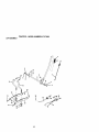
TRACTOR
TO REMOVE MOWER
Mower will be easier to remove from the
right side of tractor.
1. Place attachment clutch in =DISENGAGED" position.
2. Move attachment lift lever forward to
lower mower to its lowest position.
3. Roll belt off engine pulley.
4. Remove small retainer spring, and lif_
clutch spring off pulley bolt.
5. Remove large retainer spdng, slide
collar off and push housing guide out
of bracket.
6. Disconnect anti-swaybar from chassis
bracket by removing retainer spring.
7. Disconnect suspension arms from
rear deck brackets by removing
retainer springs,
8. Disconnect front linksfrom deck by
removing retainer spdngs.
9. Raise lift lever to raise suspension
arms. Slide mower out from under
tractor.
IMPORTANT: If an attachment other than
the mower deck is to be mounted on the
tractor, remove the front links and hook
the clutch spring Into square hole In
frame.
TO INSTALL MOWER
1. Raise attachment lift lever to its
highest position.
2. Slide mower under tractor with
deflector shield to right side of tractor.
3. Lower lift lever to its lowest position.
4. Install mower in reverse order of
removal instructions.
Small Retainer Spdng
Retainer <
Anti-Swa
Link
(BoJh Sides)
Houmng
Large Re_iner
Spnng
Bracket
23
TO LEVEL MOWER HOUSING
Adjust the mower while tractor is parked
on level ground or driveway. Make sure
tires are propedy inflated (See =PRODUCT SPECIFICATIONS" section of this
manual). If tires are over or
undednflated, you will not properly
adjust your mower.
SIDE-TO-SIDE ADJUSTMENT
• Raise mower to its highest position.
• At the midpoint of both sides of mower,
measure height from bottom edge of
mower to ground. Distance "A"on
both sides of mower should be the
same or within 1/4" of each other.
• If adjustment is necessary, make
adjustment on one side of mower only.
• To raise one side of mower, tighten lift
link adjustment nut on that side.
• To lower one side of mower, loosen lift
link adjustment nut on that side.
NOTE:Each full turn of adjustment nut
will change mower height about 1/8".
• Recheck measurements after adjusting.
Bottomedgeof
Bottomedge of
• if links are oot equal in length, adjust
one link to same length as other link.
• To lower front of mower loosen nut "E"
on both front links an equal number of
turns.
• When distance =D"is 1/8" to 1/2' lower
at front than rear, tighten nuts "F"
against trunnion on both front links.
• To raise front of mower, loosen nut "F"
from trunnion on both front links.
Tighten nut "E" on both front links an
equal number of tums.
• When distance "D" is 1/8" to 1/2" lower
at front than rear, tighten nut "F" against
trunnion on both front links.
• Recheck side-to-side adjustment.
_%,=_=_ _, . ._//aandrel
BothFrontUnksShouldbe Equalin Length
Nut "F"_
Nut=E"
Suspension Arm
Tmnnion/_
FrontLinks
Lift
FRONT-TO-BACK ADJUSTMENT
IMPORTANT: Deck must be level side-to
side. If the following front-to-back
adjustment is necessary, be sure to
adjust both front links equally so mower
will stay level side-to-side.
To obtain the best cuffing results, the
mower housing should be adjusted so
that the front is approximately 1/8" to 1/2"
lower than the rear when the mower is in
its highest position.
Check adjustment on right side of tractor.
Measure distance =D" directly in front
and behind the mandrel at bottom edge
of mower housing as shown.
• Before making any necessary adjustments, check that both front linksare
eque.!in length.
TO REPLACE MOWER BLADE DRIVE
BELT
The mower blade ddve belt may be
replaced without toots. Park the tractor on
level surface. Engage perking brake.
BELT REMOVAL1. Remove mower from tractor (See ='1"O
REMOVE MOWER" in this section of
this manual).
2. Work belt off both mandral pulleys and
idler pulleys.
3. Pull belt away from mower.
BELT INSTALLATION 4. Install new belt in reverse order of
removal.
5. Make sure belt is in all pulley grooves
and inside all belt guides.
6. Install mower in reverse order of
removal instructions.
24
Mandrel
3. Pull belt slack toward rear of tractor.
Carefully remove belt upwards from
transmission input pulley and over
cooling fan blades.
4. Pull belt toward front of tractor and
remove downward from around
engine pulley.
5. Install new belt by reversing above
procedure.
Idler Pulleys
Pulley_
Mand_
Pulley f
TO ADJUST BRAKE
Yourtractor is equipped with an adjustable
brake system which is mounted on the
side of the transaxle.
fftractorrequires more than six (6) feet
stopping distance at high speed in highest
gear on a level dry concrete or paved
surface, then brake must be adjusted.
I. Depress dutch/brake pedal and
engage parking brake.
2. Measure distance between brake
operating arm and nut =A" on brake rod.
3. If distance is other than 1-9/16", loosen
jam nut and turn nut =A" untildistance
becomes 1-9/16". Retighten jam nut
ag_dastnut "A".
4. Road test tractorfor prober stopping
distance as stated above. Readjust if
necessary. If stopping distance is still
greater than six (6) feet in highest gear,
further maintenance is necessary.
Contact a Sears or other qualified
service center.
With Parking Brake
"Engaged"
Jam Nut
perating Arm
DonottcxJchthisnut.If furtherbrakeadjustmentis
necessary,contacta Sears or other qualifiedservice
center.
TO REPLACE MOTION DRIVE BELT
Park the tractor on level surface. Engage
parking brake. For assistance, there is a
belt installation guide decal on bottom
side of left footrest.
1. Remove mower (See "TO REMOVE
MOWER" in this section of this
manual.)
2. Remove belt from stationery idler and
clutching idler.
Clutching
Stationar
Transmission
TRANSAXLE MOTION CONTROL
LEVER NEUTRAL ADJUSTMENT
The motion control lever has been preset
at the factory and adjustment should not
be necessary.
1. Loosen adjustment bolt in front of the
dght rear wheel, and lightly tighten.
2. Start engine and move motion control
lever until tractor does not move
forward or backward.
3. Hold motion control lever in that
position and tum engine off.
4. While holding motion control lever in
place, loosen the adjustment bolt.
5. Move motion control lever to the
neutral (N) (lock gate) position.
6. Tighten adjustment bolt securely.
NOTE: If additional clearance is needed
to get to adjustment bolt, move mower
deck height to the lowest position.
After above adjustment is made, if the
tractor still creeps forward or backward
while motion control lever is in neutral
position,follow these steps:
1. Loosen the adjustment bolt.
2. Move the motion control lever 1/4 to
1/2 inch in the direction it is tryingto
creep.
3. Tighten adjustment bolt securely.
4. Start engine and test.
5. If tractor still creeps, repeat above
steps until satisfied.
25
Neutral LockGate
Motion Control
AdjustmentBolt
TRANSMISSION REMOVAUREPLACEMENT
Should your transmission require
removal for service or replacement, it
should be purged after reinstallation and
before operating the tractor. See =PURGE
TRANSMISSION" in the Operation
section of this manual.
TO ADJUST STEERING WHEEL
ALIGNMENT
If steering wheel crossbars are not
horizontal (left to dght) when wheels are
positioned straight forward, remove
stearing wheel and reassemble per
instructions in the Assembly section of
this manual.
FRONT WHEEL TOE-IN/CAMBER
The front wheel toe-in and camber are
not adjustable on your tractor. If damage
has occurred to affect the front wheel toe.
in or camber, contact a Sears or other
qualified se_ce center.
TO REMOVE WHEEL FOR REPAIRS
1. Block up axle securely.
2. Remove axle cover, retaining ring and
washers to allow wheel removal (rear
wheel contains a square key - Do not
lose).
3. Repair tire and reassemble.
NOTE: On rear wheals only: align
grooves in rear wheel hub and axle.
Insert square key.
4. Replace washers and snap retaining
ring securely in axle groove.
5. Replace axle cover.
NOTE: To seal tire punctures and prevent
flat tires due to slow leaks, tire sealant
may be purchased from your local parts
dealer. Tire sealant also prevents tire dry
rot and corrosion.
Washers
RetainingRing Ars
TO START ENGINE WITH A WEAK
BAI"I'ERY
_, CAUTION: Leed-ecid batteries
generate explosive gases. Keep sparks,
flame and smoking materials away from
batteries. Always wear eye protection
when around batteries.
If your battery is too weak to start the
engine, it should be recharged. (See
=BATTERY" in the MAINTENANCE
section of this manual).
If "jumper cables" are used for emergency
starting, follow this procedure:
IMPORTANT: Your tractor is equipped
with a 12 volt negative grounded system.
The other vehical must also be a 12 volt
negative grounded system. Do not use
your tractor battery to startother vehicles.
TO AI-rACH JUMPER CABLES 1. Connect each end of the RED cable to
the POSITIVE (+) terminal of each
battery, taking care notto short
against chassis.
2. Connect one end of the BLACK cable
to the NEGATIVE (-) terminal of fully
charged battery.
3. Connect the other end of the BLACK
cable to good CHASSIS GROUND,
away from fuel tank and battery.
TO REMOVE CABLES, REVERSE ORDER1. BLACK cable first from chassis and
then from the fully charged battery.
2. RED cable last from both baftedes.
_Positive"1+)
=Negative_ (-1
LH.
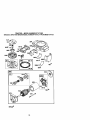
REPLACING BA'I'rERY
terminals by allowing a wrench o_=
any
other object to contact both terminals at
the same time. Before connec_ng battery,
remove metal bracelets, wristwatch
bands, rings, etc.
(_S_R,uareear
WheeIKey
Only).__._._.,_ :'q_F'..._V
26
Positive
terminal
must be connected first
to prevent sparking from accidental
grounding.
1. Lift hood to raised position.
2. Remove terminal guard.
3. Disconnect BLACK battery cable then
RED battery cable and carefully
remove battery from tractor.
4. Install new battery with terminals in
same position as old battery.
5. Reinstall terminal guard.
6. First connect RED battery cable to
positive (+) battery terminal with hex
holt and keps nut as shown. Tighten
securely.
7. Connect BLACK grounding cable to
negative (.) battery terminal with
remaining hex holt and keps nut.
Tighten securely
8. Close terminal access doors.
9. Close hood.
Terminal
Access
Door
Keps
_eadlight
tor
ENGINE
Hex
Bolt
Positive
Terminal
Wire
Cable
Negative
(Black) Cable
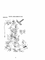
TO REPLACE HEADLIGHT BULB
1. Raise hood.
2. Pull bulb holder out of the hole in the
backside of the grill.
3. Replace bulb in holder and push bulb
holder securely back into the hole in
the backside of the grill.
4. Close hood.
INTERLOCKS AND RELAYS
Loose or damaged wiring may cause your
tractor to run poorly,stop running, or
prevent it from starting.
• Check wiring. See electrical wiring
diagram in the Repair Parts section.
TO REPLACE FUSE
Replace with 20 amp automotive-type
plug-in fuse. The fuse holder is located
behind the dash.
TO REMOVE HOOD AND GRILL
ASSEMBLY
1. Raise hood.
2. Unsnap headlight wire connector.
3. Stand in front of tractor. Grasp hood at
sides, tilt toward engine and lift off of
tractor.
4. To replace, reverse above procedure.
27
Maintenance, repair, or replacement of
the emission control devices and systems, which are being done at the
customers expense, may be performed
by any non-road engine repair establishment or individual, Warranty repairs must
be performed by an authorized engine
manufacturer's service outlet.
TO ADJUST THRO'FrLE CONTROL
CABLE
The throttle control has been preset at the
factory and adjustment should not be
necessary. Check adjustment as described below before loosening cable. If
adjustment is necessary, proceed as
follows:
1. With engine not running, move throttle
control lever to fast position,
2. Check that swivel is against side of
quarter circle. If it is not, loosen cable
clamp screw and pull cable back until
swivel is against quarter circle.
Tighten cable clamp screw securely.
TO ADJUST CHOKE CONTROL
The choke control has been preset at the
factory and adjustment should not be
necessary. Check adjustment as described below before loosening cable. If
adjustment is necessary, proceed as
follows:
1. With engine not running, move choke
control (located on dash panel) to full
choke position.
2. Remove air cleaner cover, filter and
cartridge plate to expose carburetor
choke (see "AIR FILTEW' in the
Maintenance section of this manual).
3. Choke should be closed. If it is not,
loosen casing clamp screw and move
choke cable until choke is completely
closed. Tighten casing clamp screw
securely.
4 Reassemble air cleaner.
Clamp
Quarter
Casing
Screw
TO ADJUST CARBURETOR
The carburetor has been preset at the
factory and adjustment should not be
necessary. However, minor adjustment
may be required to compensate for
differences in fuel, temperature, altitude
or load.
If the carburetor does need adjustment,
proceed as follows:
In general, turning the mixture screw In
(clockwise) decreases the supply of fuel
to the engine giving a leaner fual/air
mixture. Turning the mixture screw out
(counterclockwise) increases the supply
of fuel to the engine giving a dcher fueV
air mixture.
IMPORTANT: Damage to the needles
and the seats in carburetor may result if
screw is turned in too tight.
PRELIMINARY SETI'ING 1. Be sure you have a clean air rifler,
and the throttle control cable and
choke are adjusted properly (see
above).
2. With engine off turn idle mixture screw
In (clockwise) closing it finger tight
and then turn out (counterclockwise)
1-1/4 to 1-1/2 turns.
2. With throttle control lever in slow
position, hold throttle lever against
idle speed screw and adjust idle
speed screw to obtain 1200 to 1400
RPM.
3. While still holding throttle lever
against idle speed screw, turn idle
mixture screw In (clockwise) until
engine begins to die and then turn out
(countemlockwise) until engine runs
rough. Turn screw to a point midway
between those two positions.
4. Continue to hold throttle lever against
Idle speed screw and adjust idle
speed screw to obtain 900 to 1200
RPM. Release throttle lever.
ACCELERATION TEST5. Move throttle control lever from slow to
fast position. If engine hesitates or
dies, tum idle mixture screw out
(countemlockwise) 1/8 turn. Repeat
test and continueto adjust, if necessary, until engine accelerates
smoothly.
High speed stop is factory adjusted. Do
not adjust - damage may result.
IMPORTANT: Never tamper with the
engine governor, which is factory set for
proper engine speed. Overspeeding the
engine above the factory high speed
setting can be dangerous. If you think the
engine-governed high speed needs
adjusting, contact a Sears or other
qualified service center, which has proper
equipment and experience to make any
necessary adjustments.
__
pvrJSIdle
Speed
Screw
die Mixture
crew
o.?
Idle Speed_
Screw_
FINAL SE'FI'ING f. Start engine and allow to warm for five
minutes. Make final adjustments with
engine running and shift/motion
control lever in neutral (N) position.
t_
Thr°_trr_r
e
Screw
28
Also, experience indicates that alcohol
Immediately prepare your tractor for
blended fuels (called gasohol or using
storage at the end of the season or if the
ethanol or methanol) can aftract moisture
tractor will not be used for 30 days or
which leads to separation and formation
more.
of acids during storage. Acidic gas can
_i_ CAUTION: Never store the tractor with
damage the fuel system of and engine
gasoline in the tank inside a building
while in storage.
where fumes may reach an open flame or
1. Drain the fuel tank.
spark. Allow the engine to cool before
2.
Start the engine and let it ran until the
stodng in any enclosure.
fuel lines and carburetor are empty.
TRACTOR
• Never use engine or carburetor cleaner
Remove mower from tractor for winter
productsin the fuel tank or permanent
storage. When mower is to be stored for
damage may occur.
• Use fresh fuel next season.
a pedod of time, clean it thoroughly,
NOTE: Fuel stabili:,er is an acceptabta
remove all dirt, grease, leaves, etc. Store
alternative in minimizing the formatio(_ of
in a clean, dry area.
1. Clean entire tractor (See =CLEANING"
fuel gum deposits during storage. Add
in the Maintenance section of this
stabilizer to gasoline in fuel tank or
manual).
storage container. Always follow the mix
ratio found on stabilizer container. Run
2. Inspect and replace belts, if necessary
(See belt replacement instructions in
engine at least 10 minutes after adding
stabilizer to allow the stabilizer to reach
the Service and Adjustments section
the carburetor. Do not drain the gas tank
of this manual).
3. Lubdsate as shown inthe Mainteand carburetor if using fuel stabilizer.
nance section of this manual.
ENGINE OIL
4. Be sure that all nuts, bolts and screws
Drain oil (with engine warm) and replace
are securely fastened. Inspect moving with clean engine oil. (See "ENGINE" in
parts for damage, breakage and wear.
the Maintenance section of this manual).
Replace if necessary.
CYLINDER(S)
5. Touch up all rested or chipped paint
1. Remove spark plug(s).
surfaces; sand lightly before painting.
2. Pour one ounce of oil through spark
BATI'ERY
plug hole(s) into cylinder(s).
3. Turn ign'r_onkey to "START* pos'ition
• Fully charge the battery for storage.
for a few seconds to distributeoil,
• After a period of time in storage, battery
4.
Replace with new spark plug(s).
may require recharging.
• To help prevent corrosion and power
OTHER
leakage during long periods of storage,
• Do not store gasoline from one season
battery cables should be disconnected
to another.
and battery cleaned thoroughly (see
• Replace your gasoline can if your can
"TO CLEAN BATTERY AND TERMIstarts to rust. Rust and/or dirt in your
NALS" in the Maintenance section of
gasolir_e wlil cause problems.
this manual).
• If possible, store your tractor indoors
• After cleaning, leave cables disconand cover it to give protection from dust
nected and place cables where they
and dirt.
cannot come in contact with battery
• Cover your tractor with a suitable
terminala.
protective cover that does not retain
• If battery is removed from tractor for
moisture. Do not use plastic. Plastic
storage, do not store battery directly on
cannot breathe which allows condenconcrete or damp surfaces.
sation to form and will cause your
ENGINE
tractor to rust.
IMPORTANT: Never cover tractor while
FUELSYSTEM
engine and exhaust areas are still warm.
IMPORTANT: It is important to prevent
gum deposites from forming in essential
fuel system parts such as sarburetor, fuel
hose, or tank during storage.
29
TROUBLESHOO_NG
CHART
PROBLEM
iWill n_ _art
CAUSE
1. Out of fuel.
2. Engine not "CHOKED"
propedy,
3. Engine flooded.
CORRECTION
1. Fill fuel tank.
2. See "TO START ENGINE"
in Operation section.
3. Wait several minutes before
attempting to start.
4. Bad spark plug,
4. Replace spark plug.
5, Dirtyair filter.
5. Clean/replace air filter.
6. Dirtyfuel filten
6. Replace fuel filter.
7. Water in fuel.
7. Drain fuel tank and carbura.
tot, refilltank with fresh
gasoline and replace fuel
filter,
8. Loose or damaged widng.
8, Check all widng.
9. Carburetor out of adjustment. 9. See "To Adjust Carburetor"
in Service Adjustments
section,
10.Contact a Sears or other
10.Engine valves out of
adjustment.
qualified service center.
Herd to start
1.
2.
3.
4.
5.
Engine will not
turn over
1. Clutch/brake pedal not
depressed
2. Attachment clutch is
engaged.
3. Weak or dead battery.
4. Blown fuse.
5. Corroded battery terminals.
6. Loose or damaged widng.
7. Faulty ignition switch.
Dirty air filter.
Bad spark plug.
Weak or dead battery.
Dirty fuel filter.
Stale or dirty fuel.
t.
2.
3.
4,
5,
Clean/replace air filter.
Replace spark plug.
Recharge or replace battery.
Replace fuel filter.
Drain fuel tank and refill with
fresh gasoline.
6. Loose or damaged widng.
6. Check all widng.
7. Carburetor out of adjustment. 7. See "To Adjust Carburetor" Ir
Service Adjustments section.
8. Contact a Sears or other
8. Engine valvesout of
adjustment.
qualified service center.
1. Depress clutch/brake pedal.
9. Faulty operator presence
switch(es).
2. Disengage attachment
clutch.
3. Recharge or replace battery.
4. Replace fuse.
5. Clean battery terminals.
6. Check all widng.
7. Check/replace ignition
switch.
8. Check/replace solenoid or
starter.
9. Contact a Sears or tother
qualified service center.
Engine clicks but
will not start
1.
2.
3.
4.
1.
2.
3.
4.
Loss of power
1. Cutting too much grass/too
fast.
2. Throttle in =CHOKE"
position.
3O
8. Faulty solenoid or starter.
Weak or dead battery.
Corroded battery terminals.
Loose or damaged wiring.
Faulty solenoid or starter.
Recharge or replace battery.
Clean battery terminals.
Check all widng.
Check]replace solenoid or
starter.
1. Set in "Higher Cut" position/
reduce speed.
2. Adjust throttle control.
TROUBLESHOO_NG CHART
PROBLEM
CAUSE
Loss of power
{continued)
_ORREC_ON
3. Build-up of grass, leaves
and trash under mower.
4. Dirty air filter.
5. Low oil leveVdirtyoil.
6. Faulty spark plug.
7. Dirtyfuel filter.
8. Stale or dirty fuel.
9. Water in fuel.
10.Spark plug wire loose.
11. Dirty engine air screen/fins.
12.Dirty/clogged muffler.
13.Loose or damaged wiring.
!4.Carburetor out of
adjustment.
15. Engine valves out of
Excessive
vlbr_lon
1. Wom, bent or loose blade.
2. Bent blade mandrel.
3. Loose/damaged part(s).
3. Clean underside of mower
housing.
4. Clean/replace air filter.
5. Check oil leveVchanga oil.
6. Clean and regap or change
spark plug.
7. Replace fuel filter.
8. Drain fuel tank and refill
with fresh gasoline.
9. Drain fuel tank and
carburetor, refill tank with
fresh gasoline and replace
fuel filter.
10.Connect and tighten spark
plug wire.
11. Clean engine air screen/
fins.
12.Clean/replace muffler.
13.Check all wiring.
14.See "To Adjust Carburetor"
in Service Adjustments
section.
15.Contact a Sears or other
qualified service center.
1. Replace blade.
Tighten blade bolt.
2. Replace blade mandrel.
3. Tighten loose part(s).
Replace damaged parts.
Englnecontlnues
to run when
operator leaves
seat with
attachment
clutch engaged
1. Faulty operator-safety
presence control system,
1. Check wiring, switches and
connections. If not corrected
contact a Sears or other
qualified service center.
Poor cut - uneven
t. Worn, bent or loose blade.
1. Replace blade. Tighten
blade bolt.
2. Level mower deck.
3. Clean underside of mower
housing.
4. Replace blade mandrel.
5. Clean around mandrels to
open vent holes.
2. Mower deck not level.
3. Buildup of grass, leaves,
and trash under mower.
4. Bent blade mandrel.
5. Clogged mower deck vent
from build-up of grass,
leaves, and trash around
mandrels.
Mower blades will
not rotate
1. Obstruction in clutch
mechanism.
2. Worn/damaged mower
drive belt.
3. Frozen idler pulley.
4. Frozen blade mandrel.
31
1. Remove obstruction.
2. Replace mower drive belt.
3. Replace idler pulley.
4. Replace blade mandrel.
TROUBLESHOOTING CHART
CAUSE
PROBLEM
CORRECTION
Poor grass
discharge
1. Place throttle control in
=FAST" position.
2. Travel speed too fast.
2. Shift to slower speed.
3. Wet grass.
3. Allow grass to dry before
mowing.
4. Mower deck not level.
4. Level mower deck.
5. Low/uneven tire air pressure 5. Check tires for proper air
pressure.
6. Worn, bent or loose blade.
6. Replace/sharpen blade.
Tighten blade bolt.
7. Buildup of grass, leaves and 7. Clean underside of mower
trash under mower.
housing.
8. Mower ddve belt worn.
8, Replace mower ddve belt.
9. Blades improperly installed. 9. Reinstall blades sharp edge
down.
1O.lmpmper blades used.
10.Replace with blades listed
in this manual.
11.Clean around mandrels to
11. Clogged mower deck vent
holes from buildup of
open vent holes.
grass, leaves, and trash
around mandrels.
Headlight(s) not
working
(if so equipped)
1.
2.
3.
4.
1. Engine speed too slow.
Switch is "OFF",
Bulb(s) or lamp(s) burned cut
Faulty light switch.
Loose or damaged widng.
5. Blown fuse.
Battery will not
charge
1. Bad battery cell(s).
2. Poor cable connections.
3. Faulty regulator
(if so equipped).
4. Faulty alternator.
Loss of drive
Engine"backfires"
whenturnlng
engine
"OFF"
1.
2.
3.
4.
Tum switch "ON".
Replace bulb(s) or lamp(s).
Check]replace light switch.
Check widng and connections.
5. Replace fuse.
1. Replace battery.
2. Check]cleen all connec.
tions.
3. Replace regulator.
4. Replace alternator.
1. Freewheel control in
=disengaged" position.
2. Motion drive belt wom,
damaged, or broken.
3. Air trapped in transmission
dudng shipment or
servicmg.
t. Place freewheel control in
"engaged" position.
2. Replace motion ddve belt.
1. Engine throttle control not
set at =SLOW"
position for 30 seconds
stopping engine,
t. Move throttle control to
"SLOW" position and allow
to idle for 30 seconds before
stopping engine.
32
3. Purge transmission.
TRACTOR -- MODEL NUMBER 917.271823
SCHEMATIC
FUSE
(OP_ONAL)
i
j
I _......
i
_R
w_=
_oK
,©,_
_)e
AI(
....
w_
SEAT SWTTCH
(NOT OCCUPIED)
, ........
i,
,
I
m
j
I
i
I
%]
_=
(CLUTCH
(OPTIONAL)
_u_
i
I
i
i
GROUND NG
_
FUEL i
LINE I
r
SPARKpLuG
L
-- --
l
c_na_o svrn_ OLrmUT
FUEL SHUTOFF
'
(_ PLUGS ON
_N
CYL ENGINES)
_VOt_Sh: U_. e _O RP_
SOLENOID
(IF SO EQUIPPED)
J"Ua._NO_
NOTE
yOUR TRACTOR IS
EQUIPPED WITH A SPECIAL
ALTERNATOR
SYSTEM.
THE LIGHTS ARE NOT
CONNECTED
TO THE
BATTERY, BUT HAVE THEIR
OWN ELECTRICAL
SOURCE,
BECAUSE OF THIS, THE
BRIGHTNESS
O_ THE LIGHTS
WILL CHANGE WITH ENGINE
SPEED. AT IDLE THE LIGHTS
WILL DIM. AS THE ENGINE IS
SPEEDED UP, THE LIGHTS
WILL BECOME THEIR BRIGHTEST.
_c_
_
_
H_ADLIGHTS
NON-REMOVABLE
CONNECTIONS
tGNmON SWrTCH
REMOVABLE
CONNECTIONS
WIRING
iNSULATED
CUPS
NOTE: IF WIRING INSULATED CLIPS WERE REMOVED FOR
SERVICING OF UNIT, THEY SHOULD BE REPLACED TO
PROPERLY SECURE YOUR WIRING,
33
_e_
:
ELECTRICAL
TRACTOR - - MODEL NU MBE R 917.271823
34
ELECTRICAL
TRACTOR -- MODEL NUMBER 917.271823
KEY PART
NO. NO.
DESCRIPTION
1
2
8
10
11
12
16
21
22
24
25
26
27
28
29
30
33
40
41
42
43
45
52
55
Battery
Bo_t,He;< 1/4-20 x 3/4
Tray, Batter/
Bett, Btr Frord 1/4-20 x 7-t/2
Holddown Battew Front Mount
Nut, Push Nyton Battery Front 1/4
Switch Interlock Push-In
Harness, Ught Socket (w/4152J)
Light Bulb
Cable, Battery
Cable, Battery
Fus_
Nut Keps Hex 1/4-20 Unc
Cable, Ground
SvAtch, Seat
Switch, Ignition
Key, Molded
Hamess, Ignition
Bali BIk Fin Hex 1/4-20 UNC x 1/2
Cover, Terminal
Scienold
Ammeter Rectangular 6 Amp
Pmtecgon Wire Loop (Hour Meter)
Screw Tr=drol 5/16-18 x 1/2
163465
74760412
7603J
145211
15010G
145769
153664
166182
4152J
4799J
146148
175158
73510400
145491
121305X
175566
140403
178437
71110408
131563
178861
121433X
141940
1749_
NOTE: NI component dimensions given In U.S. inches
1 inch = 25.4 mm
35
TRACTOR -- MODEL NUMBER 917.271823
CHASSIS AND ENCLOSURES
6O
3
298
74
36
TRACTOR -- MODEL NUMBER 917.271823
CHASSIS AND ENCLOSURES
KEY PART
NO. NO.
1
2
3
5
9
10
11
12
13
14
17
18
2O
23
25
26
28
29
3O
31
37
38
51
52
53
54
55
57
58
6O
64
74
142
143
144
145
159
2O6
2O7
2_
212
°.
NOTE:
174619
176554
17(To0612
155272
168_7X013
$30533710
155S27
145660
172107X010
17490608
1442O3X558
12O938X
156437
124028X
19131312
S]Q541437
156725X558
155217X599
175692X558
139976
17490508
175710
73800400
19(_1416
145201
161464
145202
STD552507
14C547
72140606
154798
STD541437
165867
154966
175582
156524
155123X428
170165
1767(T_08
17670608
165919
5479J
DESCRIPTION
Chassis
Drawher
Screw _8-16 x 3/4
Bumper Hoo_Oa=dl
Da_/t
Bo_t,Cardage 3/8-16xl
Panel, Dash, LH
Clip "rinnerman Gdlle P/L
Panel, Dash, RH
ScTew Thdrol 3/8-1 g x 1/2
Hcod Assembly
Buxnber Hood
Plate Mtg BatteW Fuel Tank
Bushing, Snap, Nylon, Fuel Line
Washer 13/32 x 13/16 x 12 Gauge
Locknut, Hex, with Insert 3/8-15 UNC
Grille
Lens, Gdlle
FenderiFootrest
Bracket, Fender/Support
Screw, Thdro_. 5/16-18 x 1/2]_T
Pivot Bracket Assembly, LH, Mower, Rear
Nut Lock W/Insert 1/4 - 20 U NC
W_sher 9132 X 7/8 X 16 Ga.
Bracket Gd]le Pickoff LH
Screw, Hex Wshd #8-18 x 7/8
Brackut Grille Plctodf RH
Bolt FInHex 1/4 -20 UNC X.75
Air Duct
Bolt Rdhd Sqnk 3/8-16 UNC x 3/4
Dash Lower STLT
Nut Cmwnlock3i8*16 UNC
Plate Reinforcement STLT
Bracket Swaybar Chassis
Bracket Footrest STLT
Rod Plvet ChELs,sls/H
ood
Cupholder
Bolt Sheulder 5/16-18TIScrew Thdrol 3/16-18 x 1/2
Screw Thdrol 3/8-16 x 1/2
Insert, Lens
Plug BL,tton
All cof_0one_ dimensions given In U.S. inches
1 Inch = 25.4 mrn
37
TRACTOR -- MODEL NUMBER 917.271823
GROUND DRIVE
ii
212
70
116
36
2/_
32
33
38
28_.
TRACTOR - - MODEL NUMBER 917.271823
GROUND DRIVE
KEY
NO.
PART
NO.
1
......
8
10
14
15
16
19
21
22
24
25
26
27
28
29
30
_2
34
35
36
37
38
39
40
41
42
47
48
49
50
51
52.
53
55
56
57
59
31
62
63
64
165866
$30561210
10040400
7449O544
STD541431
STD541437
130564
169498
73350600
1(_888X
STD551Q_7
S]O561210
175765
71673
169592
74760512
175578
120183X
19211616
1572H
165936
74760648
175461
175556
19131312
127783
154407
12_(_5X
STD023715
STD541437
ST0541431
10o-/'10X
1057C_X
17060616
140294
169691
17G60612
8_3R
175410
71170764
DESCRIPTION
Tmnsaxle ( See Breakdown)
RHY_roGr314-O510
Shift Fender Adjust
Pin Cotter t/8 x 1 CAD
Washer Lock Hvy Hel_.al
Bolt Hex FLGHD 5/16-18 GR.5
Nut LockHexW/lns.
5/16-18 Unc
Nut Lock Hex W/Wsh 3_-16 Unc
Knob, Deluxe 1/2-13
Rod, B_ake Hydro
Nut, Hex Jam 3/8-16 Unc
Spdng, Brake ROd
Washer
Pin Cotter 1/8 x 3/4 CAD.
Rod, Paddng Stoke
Cap, Parking Brake
Bracket, Tmnsaxle
Bolt Hex Hd 5/16-18 Unc x 3/4
Shaft, Foot Pedal
Beadng, Nylon
Washer
Pin, Roll
Pulley, Composite, Flat
Bolt.FLHex 3/8-16 x 3
Spacer, Split
Keeper, BeEt Idler
Washer 13132 x 13/16 x 12 Ga.
Pulley, Idler, V-Groove
Bellcrank Clutch Gmd Dnl STL
Rntalner, Belt
Bolt
Nut Crownlock 3/6-16 UNC
Nut, Crowniock 5/16-18Unc
Link, Clutch
Spring, Return, Clutch
Screw3/6-16 x 1.0
V-Belt, Ground Drive
Keeper, Center Span
Screw 3/6-16x3/4
Cover, Pedal
Pulley, Engine
Bolt Hex 7/16-20 x 4 Gr. 5
KEY
NO.
PART
NO.
DESCRIPTION
65
66
70
71
73
74
75
76
77
78
61
02
83
84
89
90
95
96
116
120
150
151
156
158
159
161
102
163
164
165
166
168
169
197
198
199
200
202
212
$113G51143
154778
134683
169183
169182
137057
121749x
ST1_81075
123583X
121748X
175578
165711
19171216
169594
164890X428
124346X
170201
4497H
721406Ge
73_)0600
175456
19133210
166(X_
165589
1654_4
72140406
736804g0
74780416
19091010
165623
166880
165492
165580
169613
1695_3
169612
72140508
72110614
145212
WM_er
Keeper Belt Engine Hydro
Guide Belt RH Engine
Strap Torque Lh
StTap Torque Rh
Spacer, Sprit
Washer 25/32 x 1-1/4x 16Ga.
E-Ring
Key, Square
Washer 25/32 x 1-5/8 x 16 Ga.
Shaft Asm Cross
Spdng Torsion
Washer 17/02 x 3/4 x 15 Ga.
LinkTmnsaxle
Cormole, Shift
Nut Belf-Thd Wsh-hd 1/4 Zinc
Control Bypass
Retainer Spring 1" Z]ncJCad
Bolt Cart. 3/8-16 x 1
Nut 1oc_Fig 3/6-16
Spacer Rntalner
Washer 13/32 x 2 x 10 Ga.
Washer Srrted 5/161D x 1.125
Bracket Shift Mount
Hub T;zppered Flange Shltt Lt
Bolt Rdhd Sqnk 1/4-20 x 3/4 Gr. 5
NutCi-owntockl/4-20Unc
Bo;t Hex Fin 1/4-20 Unc x 1 Gr. 5
Washer 5/8 x .281 x 10 Ga
Bracket Pivot Lever
Screw 5/16-18 x 5/8
Boft Shoulder 5/16-18 x .661
PlateFastedlngLt
NylinerSnap-ln
Washer Nyliner
BoltShoulderS/16-18UNC
BoltRDHD SQNK 5/1 6-18UNC x 1
Bolt Carr SH 3/6-16 x 1.3/4
Nut Hex FIg Lock
NOTE: All component dimenstofls given In U.S. Inches
1 inch = 25.4 mm
39
TRACTOR -- MODEL NUMBER 917,271823
STEERINGASSEMBLY
,J'
4O
TRACTOR -- MODEL NUMBER 917.271823
STEERINGASSEMBLY
KEY
NO.
PART
NO.
DESCRIPTION
1
139765
Steedug Wheel
2
154427
Front Axle Assembly
3
169840
Spindle Assembly, L H.
4
169839
Spindle Assembly, R.H.
5
626_H
Beadng, Race, ThrUSt, Hardensd
6
121748X
Washer 25/32 x 1-5/8 x 16 Gauge
7
19272016
Washer 27/32 x 1-1/4 x 16 Gauge
8
120(X)029
Ring, Klip
9
3366R
Beadng, Steedng Column
10
175121
Llnl_ Drag
11
STD551137 Washer, Lock
13
136518
Spacer, Beming, Front Axle
15
145212
Nut, Hexllange Lock
17
177875
She(t Assembly, Steering
26
12_847X
BUshing, Unk, Drag
28
19131416
Washm 13/32 x 7/8 x 16 Gauge
29
17C60612
Screw 3/5-16 x 3/4
30
STD561210 Pin
32
130465
Rod, Tie
36
1550_
Bushing, Steedng
37
152927
Screw Tr #10-32 x 5 x 3/8 FlaJlge
38
139769
Insert, Steering Wheel
39
19133812
Washer 13/32 x 2-3/8 x 12 Gauge
40
STD541537 Lock NUt Center 3/8-24 UNF
41
100711L
Adaptor, Steedng Wheel
42
145054X428 Boot, Steedng Dash P/l_ Mtl Bl:<
43
121749X
Washer 25/32 x 1-1/4 x 16 Gauge
44
153720
Extension Steedn g N on-A_ust
46
121232X
Cap, Spindle
47
6855M
Fitting, Grease
51
73800500
Nut Lock Hx W/Ins 5/16-18 UNC
54
74780520
Bo_tFin Hex 5/15-13 UNC x 1-1/4
63
74780616
Bo;t Fin Hex 3/8-16 unc. x I Gr. 5
65
160367
Spacer _'ace Axle
67
72110618
Bolt Rhnd Sqnk 3/8-16 x 2-1/4
68
169827
Brace Axle
71
175146
SteedngAsm
82
169835
Bracket Susp Chassis Front
85
133835
Fastener Chdstrnas Tree
88
175118
Bo_tShoulder 7/16-20
91
175553
Clip Steering
NOTE: All component dimensions given in U.S. inches
1 inch = 25.4 mm
41
TRACTOR -- MODEL NUMBER 917.271823
ENGINE
38
32
_
_4
31
33
29
OPTIONAL EQUIPMENT
Spark Arrester
42
TRACTOR -- MODEL NUMBER 917.271823
ENGINE
KEY PART
NO. NO.
1
2
3
4
5
6
7
8
10
11
12
13
14
16
17
23
25
26
27
29
31
33
34
37
3_
39
45
51
170547
173"20410
.......
149723
144069
144068
138129
171877
145552
s'n3551125
STD522507
165287
148456
STD551237
17490624
169837
145996
73_0600
152927
137180
157103
1616_
123487X
106082X
8543R
148315
10_27X
17060612
73510400
DESCRIPTION
Control "t'hrotPaddle
Screw Hex "rhd Cut 114-20x_8 T
Engine (See Breakdown) Briggs Model No. 461707
Mutfler Exhaust
Exhaust Asm, Left
Exhaust Asm. Right
ClampTube Double E _ne
Bo_t 5/16 - 18 UNC X _,_ W/Seres
Heat Shield Lt
Washer Lock Hvy. Helical 1/4
BoltFInHex
1/4-20x3/4
Gasket Muffler
Tube, Drldn OII Easy
Washer Lock Ext Tooth 3/8
Screw 1%drol 3/8-16x1-1/2 Tytt
Shleld Browning/Debris Guard
Conic4 Choke
Nut Keps 3J8-24 Un_
Screw Tr #10-32 x 5 x _8 Rmlge
Anestor Spark
Tank Fuel 3 50 Rear
Cap Fuel Guage STLT
Clamp Hose BIg
Spacer Pad
UneFuel
Plug, Drain Oil Easy
Pad Idler 1.75 x .75 x .06
Screw 3/8-16 x SMGML
Nut, Keps 1/4-20 Starter Nut
NOTE: AJIcomponent dimensions given in U,S. Inches
1 inch = 25.4 mm
43
TRACTOR -- MODEL NUMBER 917.271823
SEAT ASSEMBLY
KEY PART
NO. NO.
1
2
3
4
5
6
7
6
8
10
11
12
140123
14_51
71110616
19131510
145OO6
$1_541437
124181X
1700G616
19131814
174894
1663_9
121246X
DESCRIPTION
KEY pART
NO. NO.
DESCRIPTION
Seat 3450 BIPJblkCraftsman
Bracket Pnt PIvo_ Seat (blk)
8c4t Fin Hex 3_-16unc X I
Washer 13/32 X 3/4 X 10 Ga
Clip push In Hi ed
Nut HeX Lock _vn_ns3/8-16 Unc
13
14
15
16
17
21
121248X
72(T_0412
134300
121250X
123976X
171852
Bushing Snap BIk Ny150 Id
Bolt Rdhd Slit Nk 1/4-20x1*1/2
spacer Sp6t 23 X 96 Zinc
Spring Cprsn I 27 BIk Pnt
Nut Lock 1/4 Lge Fig Gr 5 Zinc
Bo_tShoulder 5/16-18 Unc-2A
Spring Seat Cprsn 2 250 Bk Zi
Screw 3/8-16 x 1,5 SMGML
Washer 13/32 X 1X 14 Ga
Pan Pnt Seat (blk)
Knob Seat
Bracket Pnt Mounting Switch
22
24
25
SE)541431
19171912
127018X
Nut Hex Lock w/ins 5/16-18
Washer 17FJ2 X 1-3/19 X 12 G&
Bolt Shoulder 5/1 6-18 X 62
NOTE: AJlcomponent dimensions ghien in U.S, inches
1 inch = 25.4 turn
44
TRACTOR -- MODEL NUMBER 917.271823
DECALS
7
2
9
6
3
1
4
11
2
2O
22
19
14
14
13
15
KEY PART
NO. NO.
DESCRIPTION
1
2
3
4
5
6
7
8
9
11
13
Decal Fender Danger Sears
Decal Hoed Side
Decal Hood Rh cmgsman
Decal Hood Lh Craftsman
Decal Engine H/P
Decal Malnt Customer Sears Dora
Dec_ Replacement Srs
Decal, Chass. Disconnect
DecaJ Fender Craftsman Gold
Decal Fender STL'n-I Oper Inst E/S
Decal V-belt Dr Sch Tractor E
156439
177253
171696
171697
176681
133644
178717
178392
163204
156811
146046
KEY PART
NO. NO.
14
15
19
20
22
-----
KEY PART
NO. NO.
WHEELS & TIRES
2 ...........
_
177265
160396
138047
172331
149516
138311
165800X428
165799X428
178966
178968
1
2
3
4
5,8
4,10
5
6
7
8
9
10
11
--
DESCRIPTION
DecsI Dash Panel
Decal Mower Ddve SchematJc
Decal, Battery Diehard Sears
Decal Deck Mower EZ3
Decal Batte W
Decal Lilt Handle
Pad Footrest Lh STLT
P=ldFoetrest Rh STLT
Manual,Owner's(English)
Manual, Owners (Spanish)
DESCRIPTION
59192
65139
10_222X
59904
Valve Cap, ]Ire
Stem, Valve
31re, Front
Tube, FrontTIre
(Not Pmvtded, Senrice Item Only)
106732X427 Rim, Front
278H
Flffing, Grease (Front Wheal Only)
9040H
Bearing, Flange (Front Wheel Only)
106108X427 Rim, Rear
122082.X
33re,Rear
7152J
Tube, RearTlre
(Not Provided, Sendce Item Orgy)
104757X428 Cap, Axle
144334
Sealant, _re ( 10 oz. Tube)
NOTE: AJlcemponent dimensions given in U.S. inches
I inch = 25.4 mm
45
TRACTOR -- MODEL NUMBER 917.271823
LIFTASSEMBLY
7
5
2O
15
46
TRACTOR -- MODEL NUMBER 917.271823
LIFTASSEMBLY
KEY PART
NO. NO.
DESCRIPTION
t
2
3
4
5
6
7
8
11
12
13
15
18
17
18
19
2O
31
62
Lilt Lever Inner Wlre Asm.
Shaft Asm. Uft
Pin Groove
E Ring
Washer 21/32 x 1 x 2t Ga.
Beating Nylong
Gdp Handle Fluted
Button Plunger Read
Link Asm Lilt LH.
Link Asm Ufl R.H.
Retainer Spdng
Link Front
Nut Jam Hex 1/2-13 Uric
Trunnlc*n
Nut Lock wANsh 1/2-13 Unc
Arm Suapension Mower
Retainer Spdng
Bearing, Pvt. Lilt. Tapered
Nut Crownlock _8-24
159460
159471
105767X
12000002
19211621
120183X
125631X
122365X
162865
139866
S]I)6240_8
173288
73350800
175689
73800800
139868
163552
169865
73540600
NOTE: AJIcomponent dimensions given In U.S. inches
1 inch = 25.4 mm
47
TRACTOR -- MODEL NUMBER 917.271823
MOWERDECK
48
TRACTOR -- MODEL NUMBER 917_71823
MOWER DECK
KEY PART
NO. NO.
1
2
3
4
5
6
8
9
10
11
13
14
15
16
18
19
20
21
22
23
24
25
26
27
28
29
30
31
3_
33
34
36
37
40
44
45
46
48
4_
50
51
52
53
54
55
56
1658_
S_To33107
138017
DESCRIPTION
MoWer Housing
Bolt
Bracket Assembly,Sway Bar,
Front
165460
Bracket Sway Bar 38/42"
STD624008 RetetnerSpdng
1308_
Aim, Suspension, Rear
85(_57
Bett, Hex3/8-24x1.25Gr.
8
S'1"D551137 Washer, Lock
140296
Washer, H_dened
134149
Blede, Mulching
137645
Shatl Assembly, Mand_et, Vented
(IncI. KeyNumber6)
128774
Housln g, Mandret, Verded
110485X
Beadeg, Ball, Mandrel
17449_
Stripper, Vented Mower Deck
721405(;5
Bolt, CBrdage 5/16-18 x 5/8
132827
Bolt, Shoulder
159770
Baffle, Vortex
S'1_541431 Nut, Crownlock 5/16-18 UNC
134753
Stiffener Bracket
131267
Bracket, Deflector
105304X
Cap, Sleeve
123713X
Spdng, Torsion, Deflector
110452X
Nut, Push
130G68X428 Shleld, Defleetor
19111016
Washer 11/32 x 5/8 x 16 Ga.
131491
Red,Hinge
157722
ScrewThdro_ RoflLngWsh Hd
129963
Washer, Spacer
153535
Pulley, Mandrel
178342
Nut, Toplock, Flanged
$1_3717
Bolt
131494
P_ley, Idler, Flat
19131316
Washer 13/32 x 13/16 x 16 Ga.
s'rD541437
Nut,Crownlock5/8-16UNC
140088
Guard, Mandrel LH.
STD624003
Retainer
137729
Screw, Tnd. Roll 1/4-20 x 5/8
133944
Washer, Hardened
174284
RollerAs_embly, camFo_lower
131340
Bolt, Shou4edr# 10-24 Grade 5
STD541410
Loci(nut
139888
Bolt, Shoulder 5/16*18 UNC
131845
Arm Assembly, Pad, Brake
133943
Washer, Hardened
155046
Arm, Idler
165723
Spacer, Retatner
KEY PART
NO, NO.
59
67
68
_
101
1(_
103
104
105
106
111
112
113
114
115
116
117
118
119
121
129
130
131
142
143
144
145
146
147
148
149
150
151
152
t53
154
155
156
157
158
159
---
141043
149846
144959
STD541437
136420
71061010
19061216
ST0551110
160793
20_9J
155197
155198
17060514
73510500
72110504
4898H
165746
73930600
19121414
143723
19131312
STD523710
STD533710
165890
157109
158634
165888
171977
131335
169022
165898
19(_1216
169670
169676
169674
169675
189671
169672
169669
17720410
S]_533717
130794
169583
DESCRIPTION
Guard, Tuv Idler (94)
Knob Custom Oval
V-Belt
Lockn_, Hex W/Wsh 3/_-16 UNC
Cover Mulching 42" Black
ScrewTnJSSHdPhl110-24x5/_
Washer #10
WasherLock
LatchAsmBngger
Nut Weld
Bracket Gauge, Wheel LH
Bracket, Gauge, Wheel RH
Screw 5/16-18
NUt, Hex Keps 5/16-18 UNC
Bolt, Carriage 5/16 UNC x 1/2
Bolt, Shoulder
Wheel, Gange
Nut, Cr_nlock
5/8-1
Washer 13/32 x 7/8 x 14 G_.
Bracket
Washer 13/32 x 13/16 x 12 Ga.
Bett, Fin Hex 3/8-16 UNC x 1 Gr 5
BettRdhdSqnk3/8-16UNCxl
Arm Spdng Brake Mower
Bracket Arm Idler 42"
KeeedrBett42"ClutchCab[e
PulLeyIdler Flat
BoltCarmige Idler
Spdng Extension
Spnng Return Idler
Retainer Spring Yellow Zinc
Washer 9i32x3/4x15Ga.
Bracket Clutch
CahleClutch42"
Washer flat 3/8" Type B
SpdngRetaJner
Spring Retention Lever
Spacer
Rod Clutch
Screw Hex Thd Cut 1/4-20 x 5/8
Bc_tRdhdSqn3/8-16Uncx1-3/4
Mandrel Assembly (Includes Key
Numbers 8-10, 13-15, 31 and 32)
Replace meritMowe r, Complete
NOTE: All component dimensions given in U.S.inches
1 Inch = 25.4 mm
49
ran,
mo
19
i
I
r-O
z_
u1
o
81
73
79
_m
-L33
16
32
93
48
60
58
107
TRACTOR -- MODEL NUMBER 917.271823
HYDROGEAR TRANSAXLE - - MODEL NUMBER314-0510
KEY PART
NO. NO.
1
2
3
4
5
5
7
8
9
10
11
12
13
14
170_51
170_52
170353
170354
169698
170_55
170356
170G57
170358
170359
170360
169870
17(_61
169869
16
170_
17
18
19
23
24
27
28
29
30
31
32
170363
170364
150771
17I_65
17_66
170367
170368
170369
170370
170371
170389
33
142991
34
35
36
37
38
39
40
41
42
43
44
170390
176991
1769_2
150732
150793
1508(_
170393
170394
170395
170396
150797
45
46
47
48
49
69
51
52
176997
170_96
170999
170400
170401
1702G2
170403
170404
53
54
55
56
57
58
1704_5
1704_6
142977
142978
150798
170407
KEY PART
NO, NO.
DESCRIPTION
Main Housing, Assembly
Side Housing, Assembly
Center Sent}on, Assembly
Swgshplat e,Trunion Machteod
Block - A_sembly
Sealant 10.50z
Hex Flange Screw 1/4-20 X 1.25
Stud, 5/16-24 Hex Double End
Shaft. input
Ring - Reteining
Spacer
Ring- Rctaiaing
Seal, Lip .67 X 1.58 X .276
Bail Big 17ram Id X 40mrn Od X
lZ_m
Hex Flange Head Screw 5J1624X0.75
Lip Seal 18 X 32 X 7
Arrn, Contrc4
Bearing, 30x52x13Thrust
Check Rug Assembly, Washer
Shaft, Motor
Gear- Plrdon, !3t
1 O1,'48tGear
Gear, lot Jackshalt
60t Bull Gear
Sleeve Bearing .75 X 1.575 X .625
SteeveSearing(Outboard)
.75xl.750x.625
Washer, 3/4 Id X %1/20d X .13
l_k
Lip Seal Axle Seai
Shaft, Axle .75 X 11.39 (Key, R.H.)
Shaft, Axle .75 X 16.99 (Key, LH.)
Miter Gear (Splined)
Miter Gear 15t (0.5 Id)
Shaft
Ring, Splrat Reteinlng
Pin, Jackshaft
Ma_et, Ring
Spring, Bypass
Hydro Mtg Screw 3/8-24 X 2.5
Long
Filter
Base, Filter
Actuator, Bypass
Rod, Bypass Actuator
Arm, Bypass
ReteJning Ring .250 Extemai
Seal, L_p.741 X .250 X .250 Tc
Flat Washer, 5/8 Id X 1.00d X .05
_k
Retaining Ring
Bearing, Center Block
Spring - Hefical Compression
Washer
2Ow-50 Oil
Broke Yoke
59
60
61
32
69
17040e
142883
142881
142887
170410
64
65
69
67
68
69
70
71
142892
170411
170412
170413
170414
170415
170416
170417
72
73
74
75
76
77
78
79
80
170418
142884
170419
170420
170421
170422
142969
142980
150778
81
32
170423
170424
69
84
69
69
87
69
90
69
107
108
161162
170425
170426
170427
170424
170429
170430
170431
170432
170433
10_
111
112
113
116
119
120
121
122
123
124
170434
170435
170436
170437
170438
170439
170440
170441
170442
170443
170444
125
126
127
900
170445
170446
1"/O447
166768
51
NOTE:
DESCRIPTION
Roter, _roke
Brake Puck
Puck Plate
Brake Actua6ng Pin
Hfhc8 1/4-20_2 W/Patch.
Spuda]Range
Bolt, 1/4-20 X 1 W/Patch
Spacm
Spring, Brake Arm Bias
Sq. Hd. Bolt 5/16-24-Ribbed
Arm.Brake
Slotted Hex Nut 5/15-24
Cotter Pin 3/3_ X 3/4
Compression Spring Brake AnltDrag
Washer, Ht .5 LD. X 10.D. X .692
Flat - Washer 11/32 I.D. X 7/80,D
Oil Seat .625 X 1.0 X .25
Ch_k Plug Assembly, .027,Washer
Stud, 5/16-24 Fflctlon Pack
Puck..330 X 1.50 X .0975
Spring, Helical Comp
Spacer
Hex Lock Nut 5/16-24Unjf(Nylon
Insert)
Wedge. Friction Pack
Clip, Washer .316xl.50x.1046
(Plated)
Pin, Stendard Headless
FRtlng, 5/16 See 5/32 Tube
Hose, Expansion Tank
Expansion Tank
Cap - Poppet Valve
Bolt, Seit Tapping 10-32 X 1/2
Puok, tener Wedge
Spring Clip - Housing Tl_rust
Deflector
Washer,Motor Shatt
.711dxl.15od0(.030thk
plug, Sae #6
O-RIng.07X .301 I,D.
Shield, Vent
Bracket, Sapped Expansion Tank
SiliconSponge
Fan, 7 In.
Pulley
Hex Lock Nut 1/2-20 (Nylon Insed)
Washer, Bellevllle
BeltKeeper
Ce cte r Secttefl-Filte r-Bypass
Assembly
Filter Assembly
Fan - Pulley SewIce Assembly
Seal - O-Ring Kit
Transaxle Complete
All componect dimensions _ven In U.S. Inches
1 It:oh = 25.4 mm
TRACTOR -- MODEL NUMBER 917.271823
DRIGGS & STRATFONENGINE-MODELNUMBER 461707,TYPE NUMBER0147-E1
11058 OWNER'S MANUAL I
flOlS_BEL Kn"I
52
TRACTOR -- MODEL NUMBER 917.271823
BRIGGS & STRA'I'FONENGINE-MODELNUMBER461707, TYPE NUMBER0147-E1
212 €_
51A
51
523
_
441
122_
61
50 °_
6_
414o
4,%_,
2013.._.J
202,_--.-_
$., I
[629cgl,,_
[_1
365
llA
524 o
I
212_="'_
883
119_
107197
102_
102_
80 _7_
14_,
_--_
_...
105_
859A
" _"
"._.
51 _
394
117
104_.133 @
391 _22432._)_
26
121 CARBURETOR
102__59
_4
104_
105_
96#
OVERHAUL
117"
6o7_
KIT
_
_
276 @
14_j,,_ 392_
432_
63
1095 VALVE GASKET
OlA%
SET
TRACTOR - - MODEL NUMBER 917.271823
BRIGGS& STRA'I'TONENGINE-MODELNUMBER 461707,TYPE NUMBER0147-E1
I_.11
11036EMISSIONSLABELI
i13+
861FUELPUMPKIT
432_
392_
1119_
445
54
TRACTOR -- MODEL NUMBER 917.271823
BRIGGS & STRA'FfONENGINE-MODELNUMBER461707, TYPE NUMBER0147-E1
304
332_
934_ 75
197_r
1006
1005_
363_
695 W I
307|
I
306A_
I
865A_iI_
447
3071
8°2!
783
1051
797A
544
697_
55
;
TRACTOR -- MODEL NUMBER 917.271823
BRIGGS& STRA'I'FONENGINE-MODELNUMBER461707, TYPE NUMBER 0147-E1
KEY
NO.
1
2
3
4
PART
NO.
498583
399265
391086
493304
A
7
7A
8
0
11
12
12A
691162
691163
271867
271668
495754
27803
690334
691899
692287
692292
13
15
16
18
19
20
22
271188
271189
691681
690946
690666
495901
399264
291675
691184
22A
693972
23
24
25
691976
222698
499180
499181
499182
499183
499184
499185
499186
499187
591299
498319
498320
497912
498317
26
27
28
29
32
33
34
35
36
40
40A
42
45
46
47
46
691133
390420
691302
691597
691597
590655
691939
494553
261368
691161
691964
498542
50
51
51A
54
73
74
75
91
95
97
213290
692278
692219
93208
892527
691677
691056
693483
690718
693485
KEY
NO.
98
102
104
105
PART
NO.
807923
693509
893506
692078
Head-Cylindar No.
No. 2
1
Head-C;/lindar
,+ Gasket-C_/l_ndmHe_d #1
,+ Gasket-Cylinder Head #2
Breather Assembly
,+ Gasket-Breather
Screw (Breather Assy.)
Tube-Breather
* Gasket-Crankcase
• Gasket-Crankcase (.015)
107
108
109
117
119
693482
693505
693498
693507
693500
690720
121
122
128
693503
691926
693479
_ Gasket-Crankcase
1"005
Gasket-Crankcase I .009
Screw (CySndar Head)
Plug-Oil Drain
Crankshaft
Cover-Crankcase
Kit-Bushino]Seal
• Seal-Oil (F'_'O Side)
Screw (Crankcase Cover/
Sump)
Screw (Crankcase Cover/
Sump)
Flywheel
Key-Flywheel
PistonAssembly (Std.)
PistonAssembly (.010 "O.S.)
PistonAssembly (.020" O.S.)
PistonAssembly (.030" O.S.)
Ring Set-Piston (Std.)
Ring Set-Piston (.010"O.S.)
Ring Set-Piston 1.020 "O.S./
Ring Set-Piston _.030 "O.S.j
Lonk-pIs'LonPin
Pin-Pisto_ (Std.)
Pin-Pieton (.005 "O.S.)
Rod-Connecting (Std.)
Rod-Conrtectin 9 (.020"
Undersize)
Screw(Connecting Rod)
Valve-Exhaust
Valve-Intake
Spring°Valve (Intake)
Spring-Valve (ExhaustI
Retainer-Valve Intakej
Retainer-Valve Exhaust)
Keeper-Valve
Valve Tappet
Cam Shaft
Slinger-Oil
Sh_t Block (F_ep_c.emer_t
Engine 460707-2637-E1
Manifo d- ntake
,_1 Gasket-Intake
.+ Gasket-Intake
Screw (Intake Manifold)
Screen-Rotating
Screw (Rotating Screen)
Washer(Flywheel)
Body-Upper Carburetor
O Screw (ThroffieValve)
Shaft-Throttle
130
133
146
147
191
163
185
187
693504
693512
691639
693506
691401
600273
693148
499167
188
197
202
203
205
209
211
212
212A
219
220
222
227
235
240
267
275
276A
278
279
297
304
308
306
306A
307
309
310
311
332
RPM
691003
690364
690570
493230
690322
691273
691807
693544
690571
394348
690412
891366
590762
691206
394358
590316
693510 _+
693497
_
692810
690366
691331
495588
690960
690414
690435
691003
497506
690323
497608
691059
_t_gs:
DESCRIPTION
Cylinder Assembly
Bushing-Cylinder
• Seal-Oi!
Sump-Engine
_l
+
±
DESCRIPTION
Idle Speed K'_
_ Gasket-Carburetor Body
_ pin-Ftoat Hinge
O ValveoFIoat Needle
Body-Lower Carburetor
Valve-Choke
Shaft-Choke
(D Jet-Main (Standard)
Jet-Main {High AIStude)
Screw {Upper to Lower
Carburetor Body)
carburetor Overhaul I_t
Spacer-Carburetor
Carburetor
ID
•
included in
358
Included in
No. 121
Instudad in
1095
Inctudad in
Valve-Throftle
Float-Carburetor
Key-Timing
Jet-Pilot
Base-Air Cleaner
Gasks_-Ak"Ck_a_er
Nut (Ring Gear)
Line-Fuel (Cut to Required
Length,
Screw ((3setrolBranket)
Screw (Back Plate)
Link-MechanicalGovernor
Crank-Bell
Screw (Bell Crank)
Spring-Governor
Spring-Governed Idle
Lmk-Thro_le
LinkoThroffie
Gear-Governor
Washer Governor Lever)
Bracket-Contm
Control Lever-Governor
Sh_k_ Fuel Spray
Filter-Fuel
Screw (Casing Clamp)
Sealing Washer
Sealing Washer
Washer(Gov. Control Lever)
Screw (Valve Cover)
Nut (Air Filter Retainer)
Housing-Blower
Screw _Blower Housing)
Shield-Cylinder
Shield-Cylinder
Screw (Cylinder Shield)
Molot-S1arter
Bolt-StarterMotor
Brush Set
Nut (Flywheel)
Low Speed: 1900-2100
High Speed: 3000-3200
Engine Gasket Set. Key. No.
Carburetor Overhaul Kit. Key.
Valve Gasket Set. Key. No.
Puet Pump Kit, _(ey. No.851
NOTE: All componentdimensionsgiven in U.S.
inches 1 inch = 25.4 mm
56
TRACTOR -- MODEL NUMBER 917.271823
BRIGGS& S'rRA'I'FONENGINE-MODELNUMBER 461707, TYPE NUMBER0147-E1
KEY PART
NO. NO.
333
334
337
358
359
363
365
373
383
391
392
394
395
404
414
425
432
434
435
441
445
447
449
474
505
507
510
513
520
523
524
525
544
551
552
552A
562
573
601
615
616
629
635
643
669
691
695
697
725
726
741
742
763
789
DESCRIPTION
394891
Armature-Magneto
691061
Screw
(Armature)
802592
Sparkplug
Gasket
Set
495868
691077
Washer-Ground Terminal
691062
Flywheel Puller
690321
Screw (Carburetor)
691612
Nut (GroundTerminal)
89838
Wrench-Spark Plug
693487
Body-Fue/Pump
693491 O± Sprdng-PurnpDtaphmgm
693489 _± Dia.phragm-Carburetor
690481
Cover-Valve Chamber
690442
Washer {GovernorCrank)
691872
Washer (Bell Crank)
691675
Screw (A_ Cleaner Cover)
693492 _± Cap_Spdng
693493
Cover Diaphragm
693494
Screw Diaphragm Cover)
691176
Bracket-O F
394019
Filter-AirCleaner Cartridge
690297
Screw(Air Guide Cover)
691044
Screw (Oil Fill Bracket)
691063
Altemutor
691029
Nut (GovernorControl Lever
691972
Insulator
497606
Drive-Starter
692024
Clutch-Ddve
691084
Terminal-Ground
691385
Dipstick
692532
• Seal-DipstiokTube
690823
Tube-Dipstick
692034
Armature-Starter
690415
Cover-Valve
690553
Bushing-Governor Crank
690552
Bushing-Governor Crank
690311
Bolt (Governor Lever)
Prate-Beck
696040
95162
Clamp-Hose
690317
Retainer-Governor Shaft
491530
Crank-Governor
262539
Spdng-Throtite Return
66538
Boot-Sparkplug
496700
Retainer-AirFilter
690555
Spdng--Fdction
690657
• Seal-Governor Shaft
693149
Screw (Ring Gear)
691625
Screw (DdveCap}
280866
Shield Heat
391362
Gear-Rin9
691285
Gear-'rimJng
690328
Retainer-ERing
693059
Gear-Pinion
695050
Hamess-W'tdng
KEY PART
NO, NO.
797
797A
801
802
803
807
842
847
851
859
859A
861
865
965A
968
868A
869
870
871
871
877
883
918
934
955
967
968
971
1005
1006
1019
1036
1051
1058
1090
1095
1119
1132
1136
1137
1138
690958
Nut_mm:,Brush
Retainer)r)
693167
Nut
Brush R_ine
691967
Cap-Drive
691286
Cap-End
691427
Housin;g-_Starter
693511
O Spacer-Throttle
271170
• O-Ring Seal (Dip_ckTuhe)
495715
Dips6ck/TubeAssembly
493880
Terminal-Sparkplug
893488 _± Gasket- Carburetor Pump
693490 0± Gasket- Carburetor Pump
693502
Kit-Fual Pump
691196
Cover-Air Guide
691197
Cover-Air Guide
497656
Seal-Valve
273312
Seal-Valve
691802
Beet-Valve (Intake)
691844
Beat-Valve (Exhaust)
231218
Bushing-Valve (Exhaust)
231218
Bushing-Valve (Intake)
393456
Wire/Conneetor-Altemator
692282
• Gasket-Exhaust
393815
Hose-Vacuum (Cut to
Required Length)
691058
Screw (Fan Retainer)
693513
Plug-Carburetor
272490
Filter-Pre Cleaner
691207
Cover-Air Cleaner
691100
Screw (Air Cleaner Base)
498157
Fan-Flywheel
691247
Retainer-Fan
496726
Kit-Label
695702
Label-Emissions
691265
Ring-Retaining
274279
Owner's Manual
691293
Retainer-Brush
498047
Gasket Set-Valve
691183
Screw (Altemetor)
690353
Screw (Oil Slinger)
690329
Screw (Conlrol Bracket)
690390
Washer Control Bracket)
690330
Nut Contto Bracket
RPM Seffings:
2_
+
±
DESCRIPTION
Low Speed: 1900-2100
High Speed: 3000-3200
Included in EngineGasket Set, Key. No.
358
Included in Car'ouretorOverhaul I_t, Key.
No. 121
Included in Valve Gasket Set, Key. No.
1095
Included in Fuel Pump Kit, Key. No.861
NOTE: All component dimensionsgiven in U.S,
inches 1 inch= 25.4 mm
57
58
SUGGESTED
I
GUIDE
SIGHTING _
GUIDE
FOR SIGHTING
SLOPES
FOR SAFE
OPERATION
ONLY RIDE UP AND DOWN RiLL
NOT ACROSS HILL
"_
_q
I
/_
Operate your Tractor up and down the face of slopes (not
greater than 15 ), never across the face. Make turns gradually to prevent Upping or loss of control. Exerc|se extreme
caution
wh ne changing
direcUon
on slopes.
I
I
Forrepairofmajorbrandappliancesin yourown home...
no matterwho made it,no matterwhosoldit]
1-800--4-MY-HOM E_
(l-e0o.4e_Fo_)
'_w_/.fleal_corr
/w/rime,
dayo¢r_ghl
(u.s._.andCanada)
t
WWW,,f_e_f,.ca
For repairof carry-inproductslikewcuums, lav,_equipment,
and
electronics,
callforthenearestSears Parts and Repair Center.
1-800-488-1222
Any'_me,
dayor
r_t_(U.S.A.
or_
wv_v_
Forthe replacementparts,accessoriesand owner'smanuals
• at youneed to do-it-yourself,
callSears Partsi_rect_!
1-800-366-PART
(l-s0o-,._6-727s)
6a.m.-11 p.m., 7daysaweek
(u.s._.orel
we,v.seanL_rect
To purchase or inquireabouta SearsServiceAgreement
or SearsMaintenanceAgreement:
1-800-827-6655 (U.S.A.)
7 a.m. - 5 p.m.,CST, Men. - Sat.
pare pedir_
de mparacidr=
a
domicto,y paraorderly pieza_
1-888-,SU-HOGARsM
1-800-361-6665 (Canada)
9 a.m. - 8 p.m.EST, M - F, 4 p.m,S_
Au_
pour
servbe
e_fran_
1.800.,LE,.FOYERuc
(_
(1-88_784,-6427)
o Sears,Rod_d_andCo.
® Registered Trademark / "rMTrademark / su Service Mark of Sears, Roebuck and Co.
® Marca Reglstrada / "n_Marca de Fdbdca / sM Marca de Serviclo de Sears, Roebuck and Co.
MCMarque do commerce / MOMarque ddpos6e do Sears, Roebuck and Co.
178966 04.17.01
RH
Printedin U.S.A.