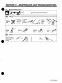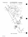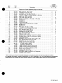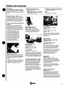
1
UM-1508
161
June 1998
Miller
The Power ofBlue.
Processes
~
MIG
(GMAW) Welding
Pulsed MIG
Flux Cored
(GMAW-P)
(FCAW) Welding
Description
Wire Feeder
(Use
DS-64M
with
CC/CV Power Sources)
Swingarc
12 and 16 Foot
Visit
our
websiie at
www.MillcrWglds.com
OWNERS
MANUAL
From Miller to You
.
-
~
;
Thank you and
you
can
congratulations on choosing Miller. Now~
get the job done and get it done right. We know
have time to do it any other way.
you dont
Thats
why
when Niels Miller first started
building arc
welders in 1929, he made sure his products offered
long-lasting value and superior quality. Like you, his
customers couldnt afford anything less. Miller products
had to be more than the best they could be. They had to
be the best you could buy.
the
people that build and sell Miller products continue the
tradition. Theyre just as committed to providing equipment and service
that meets the high standards of quality and value established in 1929.
Today,
~~1~JII~JTU?
L~i
Worldn auha~d asyosdu ~uery
This Owners
Miller
help
Manual is
products.
you protect
-
designed
help
you get the most out of your
Please take time to read the Safety precautions. They will
to
yourself against potential
hazards
made installation and
~i IJIJI
1~h
With Miller you
i~ I
I
can
on
-
iQilPie from Miller Is-
backed by the must hassle-tree
warranty in the business.
the worksite. Weve
operation quick
count
and easy.
years of reliable
on
the unit needs repair, theres a
Troubleshooting section that will help you
QUALITY SYSTEM
some reason
V
Mllleristhefirstweldingequipment
figure
manufacturer in the U.S.A. to be
ISO 9001 quality
will then
out
what the
problem
is. The parts list
decide which exact part
help you
you may need to fix the problem. Warranty and
service information for your particular model
are
also
to
provided.
-
-
Miller offers-a Technical
Manual which provides
more detailed seMce arid
prtsinformation for your
unit. To obtain a Technical
Manual, contact your local
distributor. Your disMbutor
can also supply yo~ with
WeldM9 Process Manuals
-
sucha
SM.4W, ClAW,
GMAW.andCMAW-R..
Miller Electric manufactures
welding
For information
products,
on
catalog
full line
-
equipment.
quality Miller
local Miller distributor
to receive the latest full line
individual
a
related
other
contact your
-
-
service with proper maintenance. And if for
REGISTERED
of welders and
-
-
catalog
or
sheets. To locate your nearest
distributor call 1-800-4-A-Miller.
I
-:
-
-
-:
-
TABLE OF CONTENTS
SECTION 1
-
SAFETY PRECAUTIONS
-
1-4.
1-5.
EMF Information
1-2.
1-3.
SECTION 1
1-1.
1-2.
1-3.
-
1
READ BEFORE USING
Symbol Usage
Arc Welding Hazards
Additional Symbols for Installation, Operation,
Principal Safety Standards
1-1.
1
1
3
and Maintenance
3
4
CONSIGNES DE SECURITE
-
symboles
Dangers relatifs au soudage a larc
Dangers supplØmentaires en relation
5
LIRE AVANT UTILISATION
5
des
Signification
5
avec
Iinstallation,
le fonctionnement
7
et Ia maintenance
1-4.
Principales
normes
1-5.
Information
sur
SECTION 2
2-1.
les
8
de sØcuritØ
8
champs ØlectromagnØtiques
9
INTRODUCTION
-
9
Specifications
9
SECTION 3- INSTALLATION
3-6.
Installing Swivel Into Pipe Post
Installing Control Box And Adjusting Tilt
Installing Boom And Reel Support
Installing Wire Guide Extension
Equipment Connection Diagram
Connecting Weld Cables And Gas Hoses
3-7.
Control Box Connections
3-8.
14-Pin
3-9.
Motor Start Control
3-1.
3-2.
3-3.
3-4.
3-5.
3-10.
9
10
10
11
12
13
14
14
Information
Plug
Removing Safety
15
Collar And
Adjusting
15
Boom
16
3-11. Gun Recommendation Table
Type, Size, And Feed Speed Capability
Installing And Threading Welding Wire
3-12. Wire
3-13.
SECTION 4
16
Table
17
18
OPERATION
-
18
4-2.
Operational Terms
Pulse Welding Terms
4-3.
Front Panel Controls
19
4-4.
Side And Rear Panel Controls
20
4-1.
SECTION 5
5-1.
18
21
SETTING SEQUENCE PARAMETERS
-
Sequence
Parameters In A
21
Program
22
SECTION 6- SElliNG DUAL SCHEDULE PARAMETERS
6-1.
Selecting Dual Schedule Pair
6-2.
Dual Schedule Switch
SECTION 7
7-1.
7-2.
7-3.
23
Diagrams
24
USING THE OPTIONAL DATA CARD
-
Data Card Terms
24
Installing Data
Displays
24
Card
25
Card
SECTION 8
8-1.
22
26
SYSTEM SETUP
-
System Setup Display
26
Parameters
27
SECTION 9- STANDARD PULSE WELDING PROGRAMS
9-1.
9-2.
9-3.
9-4.
9-5.
9-6.
9-7.
9-8.
Program
Program
Program
Program
Program
Program
Program
Program
SECTION 10
-
10-1. Teach
1
2
3
4
5
6
7
8
-
-
-
-
-
-
-
-
Steel
27
Steel
27
Steel
27
Steel
27
Stainless
28
Stainless
28
Nickel
28
Alloy
28
Silicon Bronze
29
TEACH POINTS
29
15 Points
Using
Using 4 Points
Redefining Teach Points
30
10-2. Teach
10-3.
SECTION 11
-
31
33
MAINTENANCE AND TROUBLESHOOTING
33
11-1. Routine Maintenance
Displays
Troubleshooting
11-2. Error
11-3.
34
35
SECTION 12- ELECTRICAL DIAGRAM
36
SECTION 13- PARTS LIST
38
OPTIONS AND ACCESSORIES
WARRANTY
OM-1 588G
.
.
.
SECTION 1
SAFETY PRECAUTIONS
-
READ BEFORE USING
-
sorn
1-1
Symbol Usage
Means
a
A
shown in the
Marks
1 .2~.
A
Watch
Warning!
hazards with this
Out!
There
possible
are
procedure! The possible
hazards
are
adjoining symbols.
Arc
not
safety
Welding
actions to avoid the hazards.
related.
Hazards
The symbols shown below are used throughout this manual
to call attention to and identify possible hazards. When you
see the symbol, watch Out, and followthe related instructions
to avoid the hazard. The safety information given below is
only a summary of the more complete safety information
found in the Safety Standards listed in Section 1 -4. Read and
follow all
Safety Standards.
If earth
with
grounding
of the
separate table
a
-
workpiece
is
required, ground it directly
clamp or work cable.
do not use work
Do not touch electrode if you are in contact with the work,
another electrode from a different machine.
ground,
or
Use
only well-maintained equipment. Repairor replace damaged
at once. Maintain unit according to manual.
parts
A Only qualified persons should install, operate, maintain,
repair this unit.
A
r1~
This group of symbols means Warning! Watch Out! possible
ELECTRIC SHOCK, MOVING PARTS, and HOT PARTS hazards.
Consult symbols and related instructions below for necessary
special safety message.
a
lET Means Note~
-~
_nd_5/97
and
During operation, keep everybody, especially children, away.
safety
Wear
a
Keep
all
worktable
Insulate work
can
kill
and
working
covers
Clamp work cable with good
or
ELECTRIC SHOCK
harness if
panels
as near
above floor level.
securely
in
place.
metal-to-metal contact to
the weld
as
workpiece
practical.
clamp when not connected to workpiece to prevent
object.
contact with any metal
Do not connect
Touching live
electrical parts can cause fatal
shocks or severe burns. The electrode and work
circuit is electrically live whenever the output is on.
The input power circuit and machine internal
circuits are also live when power is on. In semiautomatic or
automatic wire welding, the wire, wire reel, drive roll housing, and all
metal parts touching the welding wire are electrically live. Incorrectly
installed or improperly grounded equipment is a hazard.
single
weld
more
than
one
electrode
work cable to any
or
output terminal.
SIGNIFICANT DC VOLTAGE exists after removal of
input power on inverters.
Turn Off inverter, disconnect input power, and discharge input
capacitors according to instructions in Maintenance Section
before
touching any parts.
Do not touch live electrical parts.
Wear
dry, hole-free insulating gloves
and
body protection.
yourself from work and ground using dry insulating mats
or covers big enough to prevent any physical contact with the
work or ground.
FUMES AND GASES
Insulate
Do not
there is
a
Use AC
If AC
AC output in damp areas, if movement is confined,
danger of falling.
use
or
if
is
required,
use
remote
output
control if present
on
unit.
Disconnect
servicing
to OSHA 29
Properly
Owners
input power or stop engine before installing or
equipment. Lockout/tagout input power according
CFR 191 0.147 (see Safety Standards).
this
install and
Manual and
Always verify
ground
this
equipment according
to its
national, state, and local codes.
the
-
making input connections,
conductor first
-
attach
proper
grounding
double-check connections.
Frequently inspect input power cord for damage or bare wiring
replace cord immediately if damaged bare wiring can kill.
Do not
.
Do not
equipment
head out of the fumes. Do not breathe the fumes.
If inside, ventilate the area and/or
remove welding fumes and gases.
If ventilation is poor,
use an
Read
Safety
the
Material
manufacturers
worn,
drape
cables over your
body.
to
Data
Sheets
(MSDS5)
and
the
coatings,
highly
poorly spliced cables.
near
degreasing, cleaning,
or
spraying
The heat and rays of the arc can react with vapors to
toxic and irritating gases.
Do not weld
cadmium
or
arc
approved air-supplied respirator.
instructions for metals, consumables,
Do not weld in locations
form
-
when not in use.
damaged, undersized,
exhaust at the
a confined space only if it is well ventilated, or while
wearing an air-supplied respirator. Always have a trained watchperson nearby. Welding fumes and gases can displace air and
lower the oxygen level causing injury or death. Be sure the
breathing air is safe.
on
coated metals, such as galvanized, lead, or
unless the coating is removed from the
plated steel,
weld area, the
use
use
cleaners, and degreasers.
operations.
-
Turn off all
fumes and gases. Breathing
these fumes and gases can be hazardous to your
health.
Work in
supply ground check and be sure that input
power cord ground wire is properly connected to ground terminal
in disconnect box or that cord plug is connected to a properly
grounded receptacle outlet.
When
be hazardOus.
Welding produces
~
Keep your
output ONLY if required for the welding process.
output
11
can
area
is well
ventilated, and if necessary, while
wearing an air-supplied respirator. The coatings and any metals
containing these elements can give off toxic fumes if welded.
OM-1588
Page
1
ARC RAYS can
burneyesand
skin.
BUILDUP OF GAS
Shut off
Arc rays from the welding process produce intense
visible and invisible (ultraviolet and infrared) rays
that can burn eyes and skin. Sparks fly off from the
weld.
can
injure
shielding gas supply when
or
kill
not in use.
Always ventilate confined spaces
approved air-supplied respirator.
or
use
Wear
a welding helmet fitted with a proper shade offilterto
protect
your face and eyes when welding or watching (see ANSI Z49.1
and Z87.1 listed in Safety Standards).
Wear
approved safety glasses
HOT
helmet.
can cause severe
Do not touch hot
Use
protective screens or barriers to protect others from flash and
glare; warn others not to watch the arc.
Wear
PARTS
burns~
with side shields under your
Allow
parts
cooling period
bare handed.
before
working
on
gun
or
torch.
protective clothing made from durable, flame-resistant
(leather and wool) and foot protection.
material
MAGNETIC FIELDS can affect pacemakers.
WELDING
Welding
can cause fire or
explosion.
Pacemaker
Protect
yourself
and others from
Do not weld where
flying sparks
flying sparks
can
NOISE
fire,
and
that
welding
aware
can cause
fire
Do not weld
on
on
keep
a
fire
closed containers such
as
Wear
Connect work cable to the work
unknown
Do not
prevent welding
paths
use
or
equipment
and
as
approved
ear
protection
if noise level is
CYLINDERS
can
explode it damaged.
causing
or
welding area as
traveling long, possibly
electric shock and fire hazards.
welder to thaw frozen
Shielding
gas cylinders contain gas under high
pressure. If damaged, a cylinder can explode.
Since gas cylinders are normally part of the welding
process, be sure to treat them carefully.
pipes,
(see
to AWS F4.1
close to the
current from
or cut
Protect
off
welding
wire at
compressed gas cylinders from excessive heat,
slag, open flames, sparks, and arcs.
mechanical shocks,
Install
pipes.
Remove stick electrode from holder
contact tip when not in use.
cylinders in an upright position by securing to a stationary
or cylinder rack to prevent falling or tipping.
support
Keep cylinders away from any welding
Wear oil-free
protective garments such as leather gloves, heavy
shirt, cuffless trousers, high shoes, and a cap.
Remove any combustibles, such as a butane
from your person before doing any welding.
lighter or matches,
Never
drape
Never allow
Never weld
Use
a
a
welding
welding
on a
torch
over a
or
gas
other electrical circuits.
cylinder.
electrode to touch any
pressurized cylinder
-
cylinder.
explosion
will result.
only
shielding gas cylinders, regulators, hoses,
fittings designed for the specific application; maintain them
FLYING METAL
can
injure
correct
associated
eyes.
wire
brushing, and grinding
cause sparks and flying metal. As welds cool,
they. can throw off slag.
Wear approved safety glasses with side
shields even under your welding helmet.
Page
2
Keep protective cap in place
use or connected for use.
over
Read and follow instructions
associated
Standards.
and
and
parts in good condition.
Turn face away from valve outlet when
Welding, chipping,
OM-i 588
can
high.
partition
or
tanks, drums,
they are properly prepared according
Safety Standards).
to
processes
the hidden side.
unless
practical
some
damage hearing.
extinguisher nearby.
ceiling, floor, bulkhead,
on a
damage hearing.
can
Noise from
strike flammable material.
welding sparks and hot materials from welding can
go through small cracks and openings to adjacent areas.
Be
spot
or
and hot metal.
Be alert that
easily
keep away.
going near arc welding, gouging,
welding operations.
Remove all flammables within 35 ft (10.7 m) of the
welding arc. If
this is not possible, tightly cover them with approved covers.
Watch for
wearers
Wearers should consult their doctor before
closed
containers, such as tanks,
drums, or pipes, can cause them to blow up. Sparks
can fly off from the welding arc. The
flying sparks,
hot workpiece, and hot equipment can cause fires
and burns. Accidental contact of electrode to metal
objects can
cause sparks, explosion, overheating, or fire. Check and be sure the
area is safe before doing any welding.
on
equipment,
valve except when
valve.
cylinder is in
compressed gas cylinders,
publication P-i listed in Safety
on
and CGA
opening cylinder
.
1-3
Additional
Symbols
For Installation,
Operation,
And Maintenance
MOVING PARTS
FIRE OR EXPLOSION hazard
Do not install
place
or
unit on, over,
Keep away
or near
combustible surfaces.
Do not install unit
moving parts
such
Keep all doors, panels, covers,
closed and securely in place.
flammables.
injury
as
and
fans.
guards
building wiring be sure power supply system
properly sized, rated, and protected to handle this unit.
Do not overload
is
near
from
can cause
-
FALLING UNIT
can cause
injury
H~F~ RADIATION
running
only,
lifting
cylinders, or any other accessories.
Use equipment of adequate capacity to lift and
Use
can cause
intØr~tereflce.
NOT
eye to lift unit
High-frequency (H.F.) can interfere with radio
navigation, safety services, computers, and
communications equipment.
gear, gas
support unit.
electronic
The
unit.
only qualified persons familiar with
equipment perform this installation.
Have
using lift forks to move unit, be sure forks are
long enough to extend beyond opposite side of
If
having a qualified electrician
problem resulting from the
for
responsible
is
user
correct any interference
installation.
promptly
OVERUSE
Allow
can
cause OVERHEATING
cooling period;
Reduce current
starting
to weld
Do not block
STATIC
Put
or
(ESD)
on
handling
duty cycle.
follow rated
reduce
or
duty cycle
before
again.
filter airflow to unit.
grounded
or
by
at
interference, stop using the
the FCC about
once.
Have the installation
regularly
checked and maintained.
panels tightly shut,
Keep high-frequency
keep spark gaps at correct setting, and use grounding and
shielding to minimize the possibility of interference.
source
doors and
damage PC boards
can
boards
If notified
equipment
wrist
strap
BEFORE
ARC WELDING
parts.
Use proper static-proof bags and boxes to
store, move, or ship PC boards.
can cause
interference.
Electromagnetic energy can interfere with
electronic equipment such as
computers and computer-driven equipment
sensitive
MOVING PARTS
can cause
such
injury
Keep
away from
moving parts.
Keep
away from
pinch points
as
robots.
all equipment in the welding
electromagnetically compatible.
Be
such
as
To reduce
drive
possible,
rolls.
sure
WELDING WIRE
can cause
Be
injury
possible interference, keep weld cables as short as
together, and down low, such as on the floor.
welding operation
equipment.
sure
according
Do not press gun
trigger
until instructed to do
is
close
Locate
tronic
area
this
welding
100 meters from any sensitive elec
and
machine is installed
grounded
to this manual.
If interference still occurs, the user must take extra measures
as moving the welding machine, using shielded cables,
using line filters, or shielding the work area.
so.
such
point gun toward any part of the body,
people, or any metal when threading
welding wire.
Do not
other
14.
Principal Safety
Standards
Safety in Welding and Cutting, ANSI Standard Z49. 1, from
Welding Society, 550 N.W. LeJeune Rd, Miami FL 33126
Safety and Health Standards,
American
Superinten
Printing Office, Washington,
OSHA 29 CFR 1910, from
dent of Documents, U.S. Government
D.C. 20402.
Recommended Safe Practices for the Preparation for Welding and
Cutting of Containers That Have Held Hazardous Substances,
American Welding Society Standard AWS F4.1, from American
Welding Society,
550 N.W. LeJeune Rd, Miami, FL 33126
National Electrical
Code, NFPA Standard 70, from National Fire
Batterymarch Park, Quincy, MA 02269.
Protection Association,
Safe
Handling of Compressed Gases
in
Cylinders, CGA Pamphlet
P-i, from Compressed Gas Association, 1235 Jefferson Davis
Highway, Suite 501, Arlington, VA 22202.
Code for Safety in Welding and Cutting, CSA Standard Wi 17.2, from
Canadian Standards Association, Standards Sales, 178 Rexdale
Boulevard, Rexdale, Ontario, Canada M9W 1R3.
Safe Practices For
Occupation
And Educational
Eye
And Face
Protection, ANSI Standard Z87.i,from American National Standards
Institute, 1430 Broadway, New York, NY 10018.
Cutting And Welding Processes, NFPA Standard 51 B, from National
Fire Protection Association, Batterymarch Park, Quincy, MA 02269.
OM-1588 Page 3
EMF Information
1-5.
1:
Considerations About Welding And The Effects Of Low
Electric And Magnetic Fields
Welding current,
as
it flows
through welding cables,
fields. There has been and still is
magnetic
fields. However,
Frequency
1.
Keep
will cause electro
2.
Arrange
3.
Do not coil
some concern
after
examined. Until the final conclusions of the research are reached, you
may wish to minimize your exposure to electromagnetic fields when
To
or
reduce
magnetic fields
or
taping
side and away from the
one
them.
operator.
4.
or
drape
cables around your
Keep welding power
practical.
source
Connect work
to
and cables
body.
as
.
far away from opera
tor as
5.
clamp
workpiece
as
close to the weld
as
possible.
About Pacemakers:
cutting.
procedures:
cables to
together by twisting
about such
examining more than 500 studies spanning 17
years of research, a special blue ribbon committee of the National
Research Council concluded that: The
body of evidence, in the
committees judgment, has not demonstrated that exposure to powerfrequency electric and magnetic fields is a human-health hazard.
However, studies are still going forth and evidence continues to be
welding
cables close
in
the
workplace,
use
the
following
Pacemaker wearers consult your doctor first. If cleared by your doctor,
following the above procedures is recommended.
then
.
OM-1588
Page
4
SECTION 1
-
CONSIGNES DE SECURITE
UTI LISATION
LIRE AVANT
-
som
Signification
i-t
symboles
Signifie Mise en garde! Soyez vigilant! Cette procedure
prØsente des risques de danger! Ceux-ci sont identifies
par des symboles adjacents aux directives.
4A
A
des
Identifie
message de sØcuritØ
un
ru~N~d
Ce groupe de symboles signifie Mise en garde ! Soyez vigilant Ily a des
risques de danger relies aux CHOCS ELECTRIQUES, aux PIECES EN
particulier.
MOUVEMENTetauxPIECESCHAUDES. Reportez-vousauxsymboles
et auxdirectives ci-dessous af in de connaItre lea mesures a
~
Dangers relatifs
1-2.
A
au
soudage a
larc
Ne pas toucher IØlectrode quand on est en contact avec Ia
ou une electrode provenant dune autre machine.
Les symboles presentØs ci-aprŁs sont utilisØs tout au long du
present manuel pour attirer votre attention et identifier les
risques de danger. Lorsque vous voyez un symbole, soyez
vigilant et suivez les directives mentionnØes atm dØviter tout
danger. Les consignes de sØcuritØ prØsentØes ci-aprŁs ne font
ace manuel.
A
vent Œtre confiØs
A
Porter
Au coursde
un
harnais de sØcuritŁ
Maintenir solidement
lentretien
lutilisation,
qu
des personnes
reparations
qualifiees.
et les
lutilisation,tenirtoute personne a lØcart
ne
Ia
Nutiliser quun materiel en bon Øtat. RØparer ou remplacer sur-le
champ les piŁces endommagØes. Entretenir lappareil conformØment
de sØcuritØ.
Linstallation,
piŁce,
terre
que rØsumer linformation contenuedans les normes de sØcuritØ
ØnumØrØes a Ia section 1-4 Veuillez lire et respecter toutes ces
normes
prendre pour
Øviter tout danger.
nest pas relatif a Ia sØcuritØ.
NOTA
Signifie
ndtre 5/97
en
quand
place
on
travaille
en
tous lea panneaux et
hauteur.
capots.
Fixer le cable de retour de facon a obtenir un bon contact mØtal-mØtal
avec Ia piŁce a souder ou latable detravail, le plus prŁs possible de Ia
doi
soudure.
et
plus par
ticuliŁrement les enfants.
Isoler Ia
pince de masse quand pas mis a
obiet metallique.
Ia
piŁce
pour Øviter le contact
avec tout
UN CHOC
ELECTRIQUE peutluer
simple contact avec des piŁces Ølectriques peut
provoquer une electrocution ou des blessures graves.
LØlectrode et le circuit de soudage sont sous tension
des que Iappareil eat sur ON. Le circuit dentrØe et les
circuits internes de lappareil sont egalement sous
tension ace moment-l. En soudage semi-automatique ou automatique,
le fil, le dØvidoir, le logement des galets dentraInement et les piŁces
mØtalliques en contact avec le fil de soudage sont sous tension. Des
matØriels mal installØs ou ma! mis a Ia terre prØsentent un danger.
Un
Ne
toucher lea
jamais
piŁces Łlectriques
Porter des gants et des vŒtements de
pas de trous.
sous
Ily
a
DU COURANT CONTINU IMPORTANT dans Ies
aprŁs Ia suppression de Ialimenta
convertisseurs
tion Ølectrique.
ArrŒter lea convertisseurs, dØbrancher le courant electrique, et dØ
charger lea condensateurs dalimentation selon lea instructions
indiquŁes dans Ia partie entretien avant de toucher lea piŁces.
tension.
protection secs
ne
comportant
LES FLJMEES ET LES
Œtredangereux.
de Ia piŁce et de Ia terre au moyen de tapis ou dautres
moyens isolants suffisamment grands pour empŒcher le contact phy
sique Øventuel avec Ia piŁce ou Ia terre.
Sisoler
Ne pas
se
servir de
source
Ølectrique
humides, dans lea endroits confines
Se servir dune
procØdØ
de
soudage
Si lutilisation
saire,
se
source
Eloigner
UNIQUEMENT si le
arrØterle moteuravantde procŁder linstal
a lentretien de Iappareil. DØverrouiller
selon Ia norme OSHA 29 CFR 191 0.147 (voir normes
ou
ou
sØcuritØ).
Installeret mettre a laterre correctement cetappareil conformŁment a
et aux codes nationaux, provinciaux et
son manuel dutiliaation
municipaux.
Toujours verifier laterre du
Verifier et sassu
rer que le fil de terre du cordon dalimentation est bien raccordØ ala
borne de terre du sectionneur ou que lafiche du cordon est raccordØe
a une prise correctement mise a Ia terre.
cordon dalimentation
-
En effectuant les raccordements dentrØe fixer dabord le conducteur
de mise a Ia terre appropriŁ et contre-vØrifler lea connexions.
frequemment le cordon dalimentation pour voir si! nest pas
endommagØ ou dŁnudŁ remplacer le cordon immØdiatement sil est
endommagØ un cable dŁnudŁ peut provoquer une electrocution.
Mettre Iappareil hors tension quand on ne lutilise pas.
Ne pas utiliser des cables uses, endommages, de grosseur insuffi
sante ou mal epissŁs.
Verifier
-
-
Ne pas enrouler lea cables autour du corps.
Si Ia piŁce soudØe doitŒtre mise a laterre, lefairedirectementavec un
cable distinct
ne pas utiliser le connecteur de piŁce ou le cable de
votre
tŒte des fumØes. Ne pas respirer
lea fumØes.
et/ou utiliser un Øchappement au ni
des fumØes et des gaz de soudage.
Si Ia ventilation est insuffisante, utiliser un respirateur a alimenta
A
source
lation, a Ia reparation
de
l o
le demande.
Couper lalimentation
lalimentation
ou
electrique courant electrique
peUveflt
Le soudage genŁre des fumØes et des gaz. Leur
inhalation peut Œtre dangereux pour votre sante.
zones
Ølectrique courant Ølectrique savŁre nØces
Ia fonction de tØlØcommande si lappareil en est ØquipØ.
dune
servir de
Ølectrique dana lea
on risque de tomber.
courant
GAZ
IintØrieur, ventiler Ia
veau
zone
de larc pour evacuation
tion dair
homologuØ.
Lire lea specifications de sØcuritØ des matØriaux (MSDS5) et tes ins
tructions du fabricant concernant lea mØtaux, les consommables,
les revŒtements, lea nettoyants et lea dØgraisseurs.
Travailler dana
en
un
espace fermØ seulement siI eat bien veritilØ
ou
portant un reapirateur a alimentation dair. Demandertoujours a
un surveillant dQment formØ de se tenir a proximitØ. Des fumØes et
des gaz de soudage peuvent deplacer lair et abaisser le niveau
doxygŁne provoquant des blessures ou des accidents mortels.
que lair de respiration ne prØsente aucun danger.
Ne pas souder dana des endroits situØs a proximitØ dopØrations de
dŁgraissage, de nettoyage ou de pulvŁrisation. La chaleur et lea
rayons de larc peuvent reagir en presence de vapeurs et former
Sassurer
des gaz hautement toxiques et irritants.
Ne pas souder des mØtaux munis dun revŒtement, tels que lacier
galvanisØ, plaque en p10mb ou au cadmium a moinsque le revŒte
ment nait ØtØ enlevØ dans Ia zone de soudure, que Iendroit soft
bien ventilØ, et si nØceasaire, en portant un respirateur a ailments
tion dair. Lea revŒtements et toua lea mØtaux renferniant ces ØlØ
ments peuvent dØgager des fumØes toxiques en cas de soudage.
-
retour.
OM-1588 Page 5
LES RAVONS DE LARC
LES ACCUMULATIONS DE GAZ ris
voquer des brlures
sur Ia peau.
quent de provoquer desbiessures
peuvent pro
dans les yeux et
mŒme lamort.
Le rayonnement de arc du procØdØ de soudage
gØnŁre des rayons visibles et invisibles intenses
(ultraviolets et infrarouges) susceptibles de provoquer
des brOlures dans les yeux et
pendant
le
sur
Ia peau. Des Øtincelles sont
projetees
soudage.
Fermer lalimentation
non
Veiller
Porter un casque de soudage muni dun Øcran defiltre approprie pour
protØger votre visage et vos yeux pendant le soudage ou pour regar
der (voirANSi Z49. 1 et Z87. 1 ØnumØrØ dans les normes de sØcuritØ).
Porter des
protections approuves
ou
des barriŁres pour
protØger des tiers de
dair
~I
souda~e
effectuØ
Se protØger et dautres
metal chaud.
PrØvoir
une
dutiliser
le
projection dØtincelles
ou
servir dun
respi
chaudes a mains
de refroidissement avant
Ia torche.
MAGNETIQUES peuvent
affecter les stimulateurs
Porteurs de stimulateur
Les
dabord
cardiaque,
restez a distance.
consulter leur mØdecin avant de
des
de
cardiaques.
porteurs dun stimulateur cardiaque doivent
operations de soudage a arc,
soudage par points.
sapprocher
de gougeage
ou
et de
LE BRUIT
Ne pas souder dans un endroit l o
des substances inflammables.
parties
pØriode
pistolet
LES CHAMPS
sur
personnes de Ia
ou se
homologuØ.
Ne pas toucher des
des conteneurs termØs tels
que des reservoirs, tambours ou des conduites peut
provo9uerleurØclatement. Des Øtincelles peuventŒtre
projetees de larc de soudure. La projection dØtincel
les, des piŁces chaudes et des Øquipements chauds peut provoquer des
incendies et des brQlures. Le contact accidentel de lØlectrode avec des
objets mØtalliques peut provoquer des Øtincelles, une explosion, un
surchauffement ou un incendie. Avant de commencer le soudage,
verifier et sassurer que lendroit ne prØsente pas de danger.
~
de
flues
LE SOUDAGE peut provoquer
incendie ou une explosion.
Le
en cas
lØclair
lØblouissement; demander aux autres personnes de ne pas re
garder larc.
Porter des vŒtements de protection constituØ dans une matiØre dura
ble, resistant au feu (cuir ou lame) et une protection des pieds.
et de
m
protecteur
DES PI¨CES CHAU DES peuvent pro
voquer des brOlures graves.
pour les oreilles si le niveau sondre est
trop ØlevØ.
Utiliser des Łcrans
du gaz
utilisation.
toujours a bien aØrer les espaces confines
rateur dadduction
ou
I
des Øtincelles peuvent tomber
peut affecter IouIe.
sur
Le bruit des processus et des
DØplacertoutes es substances inflammables a une distance del 0,7
de arc de soudage. En cas dimpossibilitØ es recouvrirsoigneuse
ment avec des protections homologuŁs.
Des Øtincelles et des matØriaux chauds du soudage peuvent facile
Øquipements peut
affecter
roule.
m
ment passer dans dautres
zones en
traversant de
petites fissures
Porter des protections approuves pour lea oreilles si
le niveau sondre est trop ØlevØ.
et
des ouvertures.
SurvelllertoutdØclenchemeritdincendie ettenirunextincteurproxi
mite.
Le
soudage effectuØ
peut dØclencher
sur un
plafond, plancher, paroi
incendie de lautre
un
ou
Si des BOUTEILLES sont endomma
gØes, elles pourront exploser.
separation
ctØ.
Ne pas effectuer le
soudage sur des conteneurs fermØs tels que des
reservoirs, tambours, ou conduites, a moms quils naient ØtØ prepa
rØs correctement conformØment a AWS F4.1 (you les normes de
~1
_____________
Brancher te cable sur Ia piŁce le plus prŁs possible de Ia zone de sou
pour Øviter le transport du courant sur une longue distance par
des chemins inconnus Øventuels en provoquant des
risques dØlec
trocution et dincendie.
Ne pas utiliser le poste de
soudage
pour
dØgeler
des conduites ge
lees.
En
de
utilisation, enlever (a baguette dØlectrode du portecouper le fit a Ia pointe de contact.
Porter des vŁtements de protection dØpourvus dhuile tels
que des
gants en cuir, une chemise en matØriau lourd, des pantalons sans re
vers, des chaussures hautes et un couvre chef.
cas
electrode
non
ou
Avant de souder, retirer toute substance combustible de
telles quun allumeur au butane ou des allumettes.
vos
poches
DES PARTICULES VOLANTES
S
Le
soudage, lØcaillement,
a Ia brosse
en
le passage de
fil de fer, et le
a piŁce
meulage gØnŁrent
desØtincellesetdesparticules mŁtalliquesvolan
tes. Pendant Ia
de
projeter
pØriode de refroidissement des soudures,
elles
risquent
du laitier.
Porter des lunettes de sØcuritØ
avec
Øcrans latØraux
ou un
manipuler
avec
precaution.
Proteger les bouteitles de gaz comprime dune chaleur excessive,
des chocs mØcaniques, du laitier, des flammes ouvertes, des Øtin
celles et des arcs.
Placer lea bouteilles debout en les fixant dans un support station
naire ou dans un porte-bouteilles pour es empŒcher de tomber ou
de se renverser.
Tenir les bouteilles
cuits electriques.
Ne
jamais placer
eloignees des circuits de soudage ou autres cir
une
torche de
Une electrode de
une bouteille.
soudage
Ne jamais souder
une
ne
soudage sur une bouteille a gaz.
jamais entrer en contact avec
doit
bouteille
pressurisee
-
risque dexplosion.
Utiliser seulement des bouteilles de gaz protecteur, rØgulateurs,
tuyaux et raccords convenables pour cette application specifique;
les maintenir ainsi que les ØlŁments associØs en bon Øtat.
Ne pas tenir Ia tŒte en face de Ia sortie en ouvrant Ia soupape de Ia
bouteille.
peuvent blesser les yeux.
~
Des bouteilles de gaz protecteur contiennent du gaz
haute pression. Si une bouteille eat endomma
gee, elle peutexptoser. Dufaitque es bouteilles degaz
font normalement partie du procŁdØ de soudage, es
sous
sØcuritØ).
dage
.
Maintenir le
dutilisation
chapeau
ou
de
protection
sur
a
soupape, sauf
en cas
de branchement de Ia bouteille.
Lire et suivre les instructions concernant les bouteilles de
gaz cornlea equipements associØs et les publications P-i CGA Ønu
mØrØes dans es normes de sØcuritØ.
prime,
Øcran facial.
.
OM-1588 Page 6
-
1-3.
Dangers supplØrnentaires
en
relation
avec
le fonctionhement
Iinstllation,
et Ia maintenance
I RisqueDINCENDIEOU
bES.
Ne pas
placer Iappareil
proximitØ
sur,
Maintenir fermØs et fixement
lappareil a proximitØ de produits inflammables
Ne pas surcharger installation electrique sassurer que lalimen
tation est correctement dimensionnØ et protØgØ avant de mettre
panneaux,
-
en
MOBILES
peuvent
Rester a IØcart des organes mobiles
ventilateur.
au-dessus ou a
de surfaces infilammables.
Ne pas installer
lappareil
ORGANES
provoquer des blessures.
DEXPLOSION~
et
le
place es portes,
dispositifs de
protection.
service.
LA CHUTE DE LAPPAREIL
en
recouvrements
comme
LE RAVONNEMENT HAUTE FRE.
QUENCE (H.F) risque de provoquer
desinterfØrences.
peut
blesser.
Le rayonnement hautefrequence peut provoquer
des interferences avec les Øquipements de ra
dio-navigationetdecommunication, lesservices
de sØcuritØ et les ordinateurs.
Utiliser lanneau de levage uniquement pour sou
lever lappareil, NON PAS les chariot, les bouteil
les de gaz ou tout autre accessoire.
engin dune capacitØ appropriØe pour
Iappareil.
En utilisant des fourches de levage pour dØplacer lunitØ, sassurer
que lesfourches sont suftisamment longues pour dØpasser du ctØ
oppose de lappareil.
Utiliser
un
soulever
L~EMPLOI EXCESStF peut
SURCHAUFFER LEQUIPEMENT.
PrØvoir
ter le
une pØriode de ref roidissement,
cycle opØratoire nominal.
RØduirelecourantou
recommancer
Ne pas obstruer les passages dair
le
respec
Demander seulement a des personnes qualifiees familiarisØes
des Øquipements electroniques defaire fonctionner linstalla
tion.
avec
Lutilisateur est tenu de faire corriger rapidement par
les interferences resultant de linstallation.
LES CHARGES
signale des interferences, arrØter immØdiatement lappa
Effectuer
rØguliØrement
LE SOUDAGE A LARC
risque de
provoquerdes interferences.
poste.
ELECTRSTATIQUES
Ia connexion avec Ia barrette de terre
pieces.
Utiliser des pochettes et des boltes antistatiques
pour stocker, dØplacer ou expØdierdes caries de
circuits
manipuler
de linstallation.
et lentretien
lecycleopØratoireavantde
LØnergie
des caries
ou
des
imprimes.
electromagnØtique
risque
Veiller ace que tout
lŁquipement
patible electromagnØtiquement.
Pour rØduire Ia
zone
de
soudage soit com
maintenir les cables de
les grouper, et es poser aussi
possibilitØ dinterfØrence,
aussi courts que
possible,
que possible (ex. par terre).
soudage
bas
de Ia
Veiller a souder a une distance de 100 metres de tout
Ølectronique sensible.
ORGANES MOBILES
provoquer desib!essures.
DES
Ne pas
sapprocher
sapprocher
peuveæt
Veiller a ce que ce poste de soudage soit
conformØment a ce mode demploi.
Ne pas
des points de coincement
tels que des rouleaux de commande.
LES FILS DE SOUDAGE peuventpro
voquerdes.bIessures.~
Ne pas
sonnes
le fil de
le
avant den
avoir
pistolet vers soi, dautres per
ou toute piŁce mØcanique en engageant
soudage.
diriger
et mis a Ia terre
aprØs avoir pris les mesures prØcØdentes, il
de prendre des mesures supplØmentaires
le deplacement du poste, lutilisation de cables blindØs,
de filtres de ligne ou Ia pose de protecteurs dans Ia zone
telles que
lutilisation
de travail.
:;LES CHAMPSMAGNETIQUESpeuveflt
atfecterIes stimulateurs cardiaques.
Porteurs de stimulateur
gachette
pose
equipement
En cas dinterfØrences
incombe a lutilisateur
des organes mobiles.
Ne pas appuyer sur Ia
recu instruction.
de
provoquer des interferences pour Iequipement
electronique sensible tel que les ordinateurs et
Iequipement commandØ par ordinateur tel que
les robots.
primes.
Etablir
le contrle
Maintenir soigneusement fermØs les portes et les panneaux des
sources de haute frØquence, maintenirles Øclateurs a une distance
correcte et utiliser une terre et et un blindage pour rØduire les inter
fØrences Øventuelles.
peuvent endommager les circuits im
avant de
Ølectricien
Si le FCC
reil.
soudage.
du
un
qualifiØ
cardiaque,
restez a dis
tance.
Les porteurs dun stimulateur cardiaque doivent
dabord consulter leur mØdecin avant de sappro
cher des operations de soudage a larc, de gou
geage ou de soudage par points.
OM-1 588
Page
7
1-4.
Principales
normesde sØcuritØ
Safety in Welding and Cutting, norme ANSI Z49. 1, de American
ding Society, 550 N.W. Lejeune Rd, Miami FL 33126
Wel
Safety and Health Sandards,
OSHA 29 CFR 1910, du Superintendent
of Documents, U.S. Government Printing Office, Washington, D.C.
20402.
Recommended Safe Practice for the Preparation for Welding and Cut
of Containers That Have Held Hazardous Substances, norme
AWS F4. 1, de lAmerican Welding Society, 550 N.W. Lejeune Rd, Mia
ting
mi FL 33126
Safe
Handling of Compressed Gases in Cylinders, CGA Pamphlet
a Compressed Gas Association, 1235 Jefferson Davis High
Suite 501, Arlington, VA 22202.
P-i, de
way,
RŁgles
de sØcuritØ en soudage, coupage et procØdØs connexes, norCSA Wi 17.2, de lAssociation canadienne de normalisation, vente
de normes, 178 Rexdale Boulevard, Rexdale (Ontario) Canada M9W
1 R3.
me
Safe Practices ForOccupation And Educational EyeAnd Face Protec
tion, norme ANSI Z87.1, de lAmerican National Standards Institute,
1430 Broadway, New York, NY 10018.
National Electrical
Cutting and Welding Processes,
tection
Protection Association,
Code, NFPA Standard 70, de Ia National Fire Pro
Association, Batterymarch Park, Quincy, MA 02269.
Information
I -5~
DonnØes
des
le
sur
leS
et sur les
pour
lorganisme,
Atm
de
1
Le courant de
soudage, pendant son passage dans les cables de sou
dage, causera des champs ØlectromagnØtiques. II y a eu et ii y a
encore un certain souci a propos de tels champs. Cependant, aprŁs
avoir examine plus de 500 etudes qui ont ØtØ faites pendant une pe
node de recherche de 17 ans, un comitØ special ruban bleu du
National Research Council aconclu: Laccumulation
de preuves, sui
vant le jugement du comitØ, na pas dØmontrØ
que lexposition aux
champs magnØtiques et champs Ølectriques a haute frØquence reprØ
risque a Ia sante humaine. Toutefois, des etudes sont
en cours et les preuves continuent a Œtre examinØes. En at
sente un
toujours
tendant que les conclusions finales de a recherche soient Øtablies, ii
vous serait souhaitable de rØduire votre exposition aux champs Ølec
tromagnØtiques pendant
le
soudage
ou
NFPA SiB, de Ia National Fire
MA 02269.
champs ØlectromagnØtiques
soudage Ølectrique
effets,
champs magnØtiques basse frequence
sur
norme
Batterymarch Park, Quincy,
le coupage.
de rØduire les
champs ØlectromagnØtiques dans lenvironnement
travail, respecter les consignes suivantes
Garder les cables ensembles en les torsadant
attachant avec du ruban adhØsif.
2
Mettre tous les cables du ctØ
3
Ne pas courber pas et
votre corps.
4
Garder le poste de
de
5
ne
oppose
de
les
lopØrateur.
pas entourer pas
soudage
ou en
et les cables le
es
cables autour de
plus
loin
possible
vous.
Relier Ia
pince
de
masse
le
plus prŁs possible
de Ia
zone
de
soudure.
Consignes relatives
aux
stimulateurs
cardiaques
Les personnes qui portent un stimulateur cardiaque doivent avant tout
consulter leur docteur. Si vous Œtes dØclarØ apte par votre docteur, ii
est alors recommandØ de respecter es consignes ci-dessus.
.
OM-1588 Page 8
SECTION 2- INTRODUCTION
Specifications
2-1.
Type
of
24 Volts AC
Constant
Amperes
50/60 Hertz
Height
With 4 ft
(1.2
m
.023 To 1/8 in (0.6
To 3.2 mm)
pm
Max
Optional High Speed:
ipm (2.3 To
36.5 mpm)
92 To 1435
) Post
Vertical Lift Of Boom
Range
Standard: 50 To 780
(1.3 To 19.8 mpm)
Voltage (CV)
12 ft
Maximum
Wire Diameter
Speed
Range
DC For GMAW Or
Constant Voltage (CV) /
Constant Current (CC) DC
For GMAW-P
All Need 14-Pin And
Contactor Control
Single-Phase
10
Wire Feed
Welding Power
Source Type
Input
Power
Welding Circuit
Rating
100
Horizontal to 60
12 ft
Volts,
16 ft
Spool Weight:
(27 kg)
(4.9 m):
(127 kg)
280 lb
60 lb
16 ft
(4.9 m) Boom
21 ft
(5.2 m)
Above Horizontal
(3.7 m):
(94 kg)
207 lb
Amperes,
100% Duty Cycle
750
(3.7 m) Boom
17 ft
Weight
(6.4 m)
Horizontal to 60
Above Horizontal
SECTION 3-INSTALLATION
3-1.
Installing Swivel
Into
Pipe Post
5
.
1
Swingpak
2
Pipe
3
Steel Bolt
Secure
mum
Base
or
CBC Cart
Post With Base
shown
as
using
as a
mini
1/2 in diameter SAE grade 5
steel bolts.
4
Swivel
Insert
Assembly
into
pipe post.
Lubricate
swivel.
2
5
Safety
A
Do
Collar
not
remove
until
instructed to.
3
Tools Needed:
~=::~
3/4 in
ST-152 382
OM-1588
Page
9
3-2.
Installing
Control Box And
Adjusting
Tilt
1
Weld Control
2
Bracket
3
Screw
Bracket and
installed
screws are
onto bottom of control at
factory.
Swivel
4
Loosen
Place control
screws.
on
Tighten
swivel and slide forward.
screws.
2
5
Tilt Bracket
6
Rear Pivot Screw
7
Front Screw
Loosen
front
rear
pivot
screw.
Remove
Pivot control down
screw.
ward to desired
viewing angle. Re
place and tighten front screw.
Tighten pivot screw.
3~
Tools Needed:
ST-800 174! ST-801 278
3-3.
Installing
Boom And Reel
Support
1
Swivel Plates
2
Yoke
Remove
plates
3
hardware
and
Set boom into swivel
pin
5
7
as
pin through yoke. Install
and spread ends.
cot
Bolt
Install
bolt,
washers,
Tighten hardware, and
4
shown.
Yoke Pin
Install
ter
swivel
Boom
4
3
from
yoke.
one
half turn.
6
Locking
Install
and
nut.
back bolt off
Knob
locking
knob
but
do
not
tighten.
7
Reel
Support
Install reel
support.
2
Tools Needed:
~
3/8, 3/4 in
ST-15S 170
OM-1 588
Page
10
3-4.
Instafling
Wire Guide Extension
1
Wire Guide
2
Bolt
Fitting
3
Monocoil Liner
4
Wire Guide Extension
Tighten bolt to secure liner in wire
guide fitting. Do not overtighten
bolt and crush liner.
Repeat procedure
for
opposite
side.
4
Tools Needed:
tEII~~J4J
3/8 in
ST-152 383
OM-1588 Page 11
3-5.
Equipment Connection Diagram
1
300/400 Ampere Model
CC/CV Inverter Welding
Power Source
Use settings shown for both
pulse MIG welding and MIG
welding.
2
450
S
Ampere Model CV
Welding Power
Inverter
Source
3
14-Pin Cord
4
Positive
5
Negative (-)
Be
sure
Weld Cable
(+)
weld
Weld Cable
cables
are
sized
properly for peak amperage if
pulse welding (see welding power
source Owners
Manual).
PULSED
6
Workpiece
7
Voltage Sensing
(Optional Use)
.~-
W~PANEL
Be
V-SENSE
START
~*~RE~OTE
INDUCTANCE/DIG
Gun
gun is rated for peak am
perage if pulse welding. Install ac
cording to its Owners Manual.
STICK
SCRATCH
8
Lead
V/A CONTROL
9
sure
Wire Feeder
For connections
see
Gas
Section 3-7.
10
Shielding
11
Supplied
12
Gas Hose From Boom
Y
Supply
Adapter
S
ST-801 806/ Ref. ST-175 086 / Ref. sT-i 80311 -B
OM-1 588
Page
12
3-6.
Connecting
Weld Cables And Gas Hoses
The weld cables and
hoses extend lOft
shielding gas
(3 m) from the
boom.
Route
weld
through
If the
reed
cables
from
if
relays,
boom
applicable.
welding
power source or gas
further from the boom,
extend cables or hoses as follows:
supply
are
1
Weld Cable
2
Insulated
Bolt
Sleeving
together
welding power
weld
Use electrical
tape
sleeving
3
cables from
source
and boom.
and insulated
to cover connection.
Shielding Gas Hose
Connect hose to gas supply or ex
tension hose. The hose from the
boom
has
threads.
5/8-18
right-hand
Tools Needed:
~-_
5/8 in
R&. ST-801 806 / Ret. ST-152 800-A
OM-1 588
Page
13
Control Box Connections
3-7.
Optional
Reed
Relay
Connection
2
Wire Feed Motor And Gas
Valve Control
3
Receptacle
Wire Feed Motor And Gas
Valve Control
Plug
From
Boom
4
14-Pin Cord
5
Volt Sense Lead
(Optional
Use)
oIJ~
6
Gun
Trigger Plug
From Boom
0
10
2
ST-800 177-A/ Ref. ST-800 175
3-8.
14-Pin
Plug Information
REMOTE 14
*The
remaining pins
OM-1588 Page 14
are
Pifl*
Pin Information
A
24 volts
B
Contact closure to A
G
Circuit
C
+10 volts dc output to remote control with
D
Remote control circuit
common.
E
0 to +10 volts dc
command
H
Voltage feedback;
0 to +10 volts dc, 1 volt per 10
F
Current
0 to +10 volts dc, 1 volt per 100 amperes.
M
CC/CV Select (+24
N
Inductance
not used.
ac
with
common
respect
to socket G.
completes
24 volts
ac
contactor control circuit.
for 24 volts AC circuit.
input
feedback;
(0-10 V)
V
=
CV)
respect
signal from
to socket D.
remote control with
arc
volts.
respect
to socket D.
Motor Start Control
3-9.
change wire feed starting speed
proceed as follows:
To
Turn Off wire feeder and
power
welding
source.
Remove wrapper.
1
2
Motor Board PCi
Motor Start Control Poten
tiometer R70
Turn
potentiometer clockwisetoin
time it takes the motor to
crease
speed.
ramp up to
Remove protec
tive white rubber cap before mak
ing adjustment. Adjust potentiome
using a small nonconduc
ter R70
tive screwdriver.
Reinstall wrapper.
Tools Needed:
Non-Conductive
-
c::I:I::::z:J=:==11
1/4 in
ST.162 132 / Ref. SA-183 121-B
3-10.
Removing Safety
Collar And
Adjusting
Boom
1
Knob
Locking
knob
Tighten
to
prevent
boom
movement. Loosen knob to allow
movement. Change knob
position to limit upward movement.
boom
Pull boom down
move
safety
slightly
and
re
collar. Boom should
position from hori
degrees above hori
necessary, adjust boom
balance in any
zontal to 60
zontal. If
as follows:
2
Threaded Rod
3
Jam Nut
Loosen
jam
nut and turn threaded
rod until boom balances.
jam nut. Be sure
threads are through
vent boom falling.
4
E
Tighten
several
yoke
Yoke
safety collar for use in
assembling or moving boom.
Retain
0
full
to pre
dis
Rod
Tools Needed:
.~
1-1/8 in
Increasing Spring
Decreasing Spring
Pressure For A
Pressure For A
Heavy
Gun
Ughter
Gun
5T-142 599-B
OM-1 588
Page
15
3-11. Gun Recommendation Table
Process
GMAW-P
GMAW
FCAW
-
Hard
Hard
or
or
Cored Wires
Speed
GW-500 Or GW-600
Cored Wires
M25, M40, Or GA-50C
Self-Shielding Wires
Wire
GA-4OGL Or GA-5OGL
And Feed
Type, Size,
3-12. Wire
Motor
-
-
Gun
Type
Speed Capability
Table
Wire Size
Feed
Standard
All
Standard
All
3/32 To 7/64 in (2.4 To 2.8 mm)
Standard
All
1/8 in (3.2 mm)
Optional High
All
.023 To 5/64 in
.023 To 5/64 in
(0.6
(0.6
To 2
To 2
mm)
Speed Capability
50 To 780
ipm (1.3
To 19.8
mpm)
50 To 700
ipm (1.3
To 17.8
mpm)
50 To 300 pm
mm)
92 To 1440
(1.3
ipm (2.3
To 7.6
mpm)
To 35.6
mpm)
.
.
OM-1588
Page
16
3-13.
Installing
And
Threading Welding
Wire
Tools Needed:
3/16,5/64 in
~ 15/16,3/8in
0
wire
Install
El
Adjust tension
wire
is
wire feed
taut
spool.
nut so
when
stops.
4,
4-
NONCONDUCTIVE
SURFACE
No Wire
lET Be
NONCONDUCTIVE
SURFACE
Slip
that outlet cable has proper
size liner for the welding wire size.
sure
When installing gun, position liner
extending from outlet wire guide as
close as possible to drive rolls without
touching.
Install gun. Lay gun cable out straight. Cut
offend of wire. Push wire through guides up
Wire
Slips
ii:r Forsoft wire or small diameter stainless
steel wire, use2drive rolls and set drive
roll pressure from 0 to a maximum of 4
on the pressure indicator scale (so that
the inner spring is compressed).
setting will generally give the best
performance for these types of wires.
only
This
To
adjust
drive roll pressure, hold nozzle
(51 mm) from nonconductive
surface and press gun trigger to feed wire
against surface. Tighten knob so wire does
not slip. Do not overtighten. If contact tip is
completely blocked, wire should slip at the
about 2 in
feeder
(see pressure adjustment above).
Cut wire off. Close
Repeat
cover.
for other side.
to drive
Jog
rolls; continue to hold wire. Press
button to feed wire out gun.
ST-i 52 564-B / Ref. ST-156 92g / Ref. SC-i 50922 / Ref. ST-i 56 930/ 5-0621-A
OM-1 588
Page
17
SECTION 4- OPERATION
4-1.
Operational
Note ~
The
following
is
a
Terms
See Menu Guide for detailed
list of terms and their definitions
as
programming steps.
they apply
to this wire feeder:
General Terms:
Adaptive
Pulse
Welding
The wire feeder
less of
Cold Wire
change
automatically regulates pulse frequency
welding wire stickout.
to maintain
a
constant
arc
length, regard
in
When weld amperage is not present, wire feeds for about three seconds at set wire feed speed.
Then the welding power source contactor deenergizes and wire continues to feed at the wire jog
Jog
speed.
Inductance
As inductance
Trim
Arc
Synergic
The operator programs pulse parameters for a specific wire teed speed. The wire feeder determines
the pulse parameters between these wire feed speed increments.
increases,
arc on
time increases, and the weld
length adjustment in pulse welding. Increasing
placed by volts in MIG programs.
puddle
becomes
more
trim increases the actual arc
fluid.
length.
Trim is
re
Side Panel Terms:
Process Mode
Sequence
Is used to select the
Mode
type
of process to be used,
including Pulse, Adaptive Pulse,
or
Mig.
Is used to select and program the weld sequences which include weld, crater, burnback,
and run-in.
postflow,
preflow,
Dual Schedule Mode
Is used to select
a
Card Mode
Is used to select
use
Security
Only
Mode
functions with
rameter
4-2.
Pulse
Welding
pair
a
of programs that can be used
of the
optional
data card
data card. Allows
using
together.
storage and retrieval capabilities.
the lock feature for
restricting range
of program pa
changing.
Terms
Apk
1
Peak
=
Amperage
Increasing Apk increases penetra
tion.
Vpk
Peak
=
Voltage
voltage during peak current
phase of the pulse waveform. This
determines
arc
length during
adaptive pulse welding.
Arc
3
/ \
2
Abk
Background Amperage
=
Maintains
3
PPS
4
1
Increasing
2
Time
18
/
pulses.
increases travel
PWms
Pulse Width In
Milliseconds
width.
Page
between
Pulses Per Second
Increasing PPS
speed.
Amps
OM-1 588
=
arc
=
PWms increases bead
Front Panel Controls
4-3.
1
Ii~.a..
I
2
3
8
ow~7
4
4
//
ST-162 ~27
1
Display
while welding, with
ule Mode
2
Parameter Select Button
Press button to
3
Display
move > on
change value pointed to by>.
4
Active Side Indicator
5
Trigger
Trigger Hold
When 1PM is selected,
click causes wire feed
To weld without
crease/decrease by
When MPM is
clicks
causes
by
0.1.
Prg
# is
crease
When
click
selected, turning control three
wire feed speed (MPM) to in
selected, turning control
one
program number (Prg #) to in
crease/decrease by
one.
The program number cannot be
changed
Light
holding gun trigger through
cycle, press and release button to
feature on (indicator light turns on).
To start weld cycle, press and release gun
trigger within three seconds after an arc has
been struck. To end weld cycle, press and
6
trigger may be
used to
change
trigger.
Side Select Button
The feeder remembers the last used pro
gram for each side and returns to that pro
gram when the active side is changed.
Jog
Button
momentarily feed welding wire with
energizing welding circuit or shielding
Push to
gas valve.
Jog speed is varied using the Display Con
trol while Jog button is pressed. Default set
ting is 200 1PM.
8
out weld
release gun
causes
7
out
can be set on a per program ba
sis, Indicator light comes on for programs
where this feature is active.
turn
one.
Light
Hold Button And Indicator
Turning control one click causes Trim (arc
length) to increase/decrease by one or Volt
to increase/decrease by 0.1.
turning control one
speed (1PM) to in
The gun
active side of the feeder.
Pulse is a default setting. To change type of
process (Pulse, Adaptive Pulse, or M IG) use
side panel controls (see Section 4-4).
display.
Control
Turn control to
exception of Dual Sched
(see Section 6).
Purge
Button
momentarily energize gas valve
energizing the welding circuit.
Push to
without
lt7
Jog
and
Purge only
work
on
the active
side of the feeder.
Holding the Jog and Purge buttons at the
time displays pulse parameters on
the side panel display and voltage on
front panel display.
same
OM-1 588
Page
19
4-4.
Side And Rear Panel Controls
1
Mode
2
Mode Select Button
Display
Press button to
move>
3
Parameter
Display
4
Parameter Select Button
in
Press button to move> in
display.
display.
5
Parameter Increase Button
6
Parameter Decrease Button
7
Power Switch
8
Circuit Breaker CB1
CB1 protects the wire feeder from
overload.
5
6
2
Ret. ST-162 128/ Ref. ST-162 133
OM-1 588
Page
20
SECTION 5- SETTING SEQUENCE PARAMETERS
ience
Parameters In A Program
OM-1588
Page
21
SECTION 6
6-1.
Selecting
-
SETTING DUAL SCHEDULE PARAMETERS
Dual Schedule Pair
H
Dual Schedule is used with two
consecutive weld programs 1 & 2,
3&4, 5&6, or7&8.Anyprogram
type (MIG, Adaptive Pulse, or
_____________________
Pulse)
can
be combined in dual
schedule.
Side Panel
1
Use side
See
panel
Menu
Display
to turn feature
Guide
for
on.
detailed
programming steps.
2
Front Panel
Display
Press front
panel parameter select
button to select program number.
3
Front Panel
4
Dual Schedule Switch
Section 6-2)
UJ
Switch
type
Display
Control
is set in
(See
System
Setup.
5
Welding Gun Trigger
Selecting dual schedule program A
or B is done by using Display Con
trol, dual schedule switch,
trigger
setup).
(depending
on
or
gun
system
When program B is active, turn
Display Control one click clock
wise to select another pair of dual
schedule programs.
~
Programs
in
be
rearranged
desired order using the data
can
.
card. See Section 7.
2
ik
Al
__________________
24.
250
OV
1PM
I>Prg
Dual
3
Or
c~
Display
Control
5
.
OM-1 588
Page
22
6-2.
Dual Schedule Switch
Diagrams
1
Momen 2P
(Momentary-Contact
2-Pole
Switch)
2
1
1
2
2
>
>
(Maintained-Contact
Switch)
Maint 2P
2-Pole
3
Maint 1 P (Maintained-Contact
1-Pole Switch)
4
Trigger
scheduling after estab
welding arc.
Allows dual
lishing
A
3
1
2
>
0
a
fl~ If trigger is used for dual
schedule switch, Trigger Hold
is disabled.
B
4
0
3
4
1
>
TRI\
2
>
3
IBO
4
0
3
Adapter
1
>
2
>
TR\___
3
>>
A~
OM-1 588
Page
23
SECTION 7- USING THE OPTIONAL DATA CARD
7-1.
Data Card Terms
CARD SCREEN TERMS
WRITE
Programs
To Card
~
READ
Programs
From Card
PULSE MIG TERMS
PPS
Amperage
(Pulses Per
Second)
I
I~
I
PWms
Width In
(Pulse
Milliseconds)
-r
Apk (Peak
Amperage)
-r
Abk
Time
(Background
Amperage)
SA-158 435
7-2.
Installing
Data Card
1
Label
Apply
label to data card. Write pro
gram information on label.
2
Data Card
3
Card Slot
For Blank Data Card:
Insert card into slot. Toformatcard,
3
turn On power. Select Card from
menu.
Data card formats when unit
enters Card mode.
For Power Source Data Card:
Insert card into slot. Turn On pow
Push Parameter Select button
within 3 seconds and the 8 pro
er.
grams and setup information are
read into the wire feeder memory.
Unit is
ready
Wait
message disappears from
front
to use when Please
panel display.
.
ST-i 56 266-B
OM-1 588
Page
24
7-3.
Card
Displays
f~ See Menu Guide for detailed
programming steps. Security
mode only functions with a
data card.
Display
1
Card
2
Moving
Line
Moving line is
be changed.
Sequ
ence
3
under value that
can
Write
Dual Schd
Pr
>Card
Secu
r
ty
ess
Be low
Transfers program data from unit
to card. The program card can hold
up to 32 programs. When writing to
the card, the next available pro
gram number is
automatically
as
signed.
Side Panel
Parameter
Select Once
4
Transfers program data from card
to unit.
5
3
Read
Delete
Deletes program data from card.
6
Done
4
Exits card
display.
5
6
OM-1 568
Page
25
SECTION 8- SYSTEM SETUP
8-1.
System Setup Display
Note ~
DISPLAY SETTING
*
>System
>Range
See Menu Guide for detailed
programming steps.
NOTES
Select the process the
*
.
Parameters
welding power
source
is able to do.
Welding power source minimum and maximum voltage values are always
pulse welding. Set values to match welding power source ranges.
needed.
values
Amperage
are
required
for
>Access
When on, restricts
of
>Mig Type
Default is Off. Set to On
>Voltage
Default is
use
setup
only
14-pin receptacle.
screens.
for older CV
welding power
Use V. Sense when
more
source
without
than 50 ft
(1 5m)
voltage feedback
at 14-socket
of weld cable is used
receptacle.
(including gun
cable
length).
>Arc Start~
Use Hot Start only with Inverter Model
switches to CC.
>Dual Schedule
See Section 6-2.
>Trigger
When on,
trigger
can
welding power
source
and
large
diameter wires. The
be used to switch between programs that have at least 0.2 seconds of
arc
starts in CV and
time pro
preflow
grammed.
>Remote
When on,
a
dual schedule switch
panel display>
can
be used to
change
Volts
or
Trim, 1PM,
Prg depending
on
where the front
>Arc Time
Displays
>Wire Feed
Choose to
>Memory
Program Reset: unit defaults to original factory setting for the last active program. Setup information
change. If setup card is in card slot, program will be loaded from card.
accumulated
display
arc
time and
cycles.
inches per minute
or
meters per minute and motor
type,
Reset: unit defaults to original factory settings for all programs and
card is in card slot, program will be loaded from card.
System
setup
Total Reset: unit defaults to
setup
*
or
is.
When on, the system
age is sensed.
>Teach
Default is 15 points, but
>Gas Flow
Setting
>Software
Know this when
Can be used
--
for all programs and
setup excluding System
does not
and Arc Time. If
setup including System and
.
Arc Time. If
card is in card slot, program will be loaded from card.
>Shutdown
Automatically
original factory settings
but installed motor must match selection.
immediately
can
must be Meter Off if
talking
shuts down if
be set to 4
option
no arc
voltage
is sensed. When off, wire feeds
even
if
no arc
volt
points.
is not installed.
with service
personnel.
set if power source data card is used.
only when optional data card is inserted.
Selection does not appear on display when MIG Only is System choice.
Must remain set to Meter Off if option is not installed to prevent system
error.
.
OM-1 588
Page
26
SECTION 9- STANDARD PULSE WELDING PROGRAMS
Note ~
Apk
Peak
=
PPS
=
Amperage, Vpk
factory set programs.
interpolations from the
9-1.
Wire
Program
Sizefrype:
1
-
=
Peak
Pulses Per Second, PWms
=
If selection is set
4
Abk
Background Amperage,
(milliseconds). Four teach points were use d for
for fifteen teach points, the remaining points are
Voltage,
Pulse Width
taught points.
Steel
Gas: Ar
.035
-
CO2
or
Ar
Oxy /
-
40 CFH
(19 Urn)
Vpk
Abk
PPS
PWms
440
36.7
160
180
2.9
400/10.2
385
32.4
108
126
2.3
200/5.1
335
28.7
61
81
2.0
100/2.5
328
27.4
37
47
1.7
1PM / MPM
Apk
700/17.8
9-2.
Wire
Program
Size/Type:
2
-
Steel
Gas: Ar
.045
-
CO2
or
Ar
-
Oxy /40
CFH
(19 U/rn)
1PM / MPM
Apk
Vpk
Abk
PPS
PWms
700/ 17.8
518
35.0
195
205
3.6
400/10.2
466
31.3
147
158
2.9
200 / 5.1
412
28.5
93
106
2.4
100 / 2.5
375
26.5
50
66
2.2
9-3.
Wire
Program
Size/Type:
3
-
Gas: Ar
Apk
625/15.9
-
CO2
or
Ar
-
Oxy /
40 CFH
(19 Urn)
Vpk
Abk
PPS
PWrns
560
39.3
200
229
3.6
400/10.2
525
36.2
148
189
3.5
200/5.1
475
31.7
102
131
2.7
100 / 2.5
445
29.6
50
80
2.4
9-4.
Wire
Program
Size/Type:
1PM / MPM
4
-
.062
Gas: Ar
-
CO2
or
Ar
.
Oxy /
40 CFH
(19 Urn)
Vpk
Abk
PPS
PWrns
550
36.8
200
195
4.1
300/7.6
510
36.3
145
175
3.8
200/5.1
480
31.6
110
155
3.2
100/2.5
460
28.7
69
94
2.6
/ 10.2
COMMENTS
Steel
Apk
400
COMMENTS
Steel
.052
1PM / MPM
COMMENTS
COMMENTS
OM-1588
Page
27
9-5.
Program
Wire
Size/Type: .035
5
-
Stainless
Gas: Ar
-
He
-
CO2 /
40 CFH
(19 L/m)
1PM / MPM
Apk
Vpk
Abk
PPS
PWms
700) 17.8
403
33.9
132
191
2.8
400/10.2
318
31.6
87
146
2.4
200/5.1
295
28.5
53
94
1.9
100/2.5
280
26.0
32
45
1.8
9-6.
Wire
6
Program
-
Stainless
Gas: Ar
Size/Type: .045
-
He
-
CO2 /40 CFH (19 Urn)
1PM / MPM
Apk
Vpk
Abk
PPS
PWms
700/17.8
480
39.0
200
227
3.2
400/10.2
425
32.4
155
185
2.5
200/5.1
360
28.0
100
115
2.0
100/2.5
350
26.2
40
70
2.0
9-7.
Wire
Program
Size/Type:
.035
7
-
Nickel
Nickel
Gas: Ar
Alloy
-
He / 40 CFH
(19 U/rn)
Apk
Vpk
Abk
PPS
PWms
700/17.8
350
34.5
130
144
3.7
400/ 10.2
310
30.0
80
105
3.3
200/5.1
280
27.5
48
55
2.9
100/2.5
260
25.1
28
36
2.5
Wire
Program
Size/Type:
.035
8
-
COMMENTS
Alloy
1PM / MPM
9-8.
COMMENTS
COMMENTS
.
Silicon Bronze
SiBr
Gas:
Argon /
40 CFH
(19 U/rn)
IPM/MPM
Apk
Vpk
Abk
PPS
PWms
510/13.0
340
30.7
100
125
3.7
400/10.2
310
29.8
83
97
3.4
200 / 5.1
277
26.6
48
55
3.0
120/3.1
242
25.2
31
31
3.0
COMMENTS
.
OM-1588
Page
28
SECTION 10- TEACH POINTS
10-1. Teach
Using
15 Points
L~
Apk
=
Peak
Amperage
A
Vpk
=
Peak
Voltage
o
Abk
=
Background Amperage
O
PPS
1PM / MPM
=
PWms
Pulses Per Second
=
Pulse Width
(Milliseconds)
780/ 19.8
750/19.1
700/17.8
650/16.5
600/15.2
550 / 14.0
500 / 12.7
450/11.4
Example Of A Synergic
Setting For 425 1PM With
400 / 10.2
All Teach Points Set At 50
(1.3 MPM) Increments
1PM
350/8.9
300/7.6
250 / 6.4
200/ 5.1
150/3.8
100/2.5
50/1.3
Apk
Vpk
100
180
210
240
270
300
330
360
370
420
24
27
30
33
36
37
42
10
20
30
40
50
60
70
80
90
100
110
120
130
PPS
20
55
80
105
130
160
185
210
235
260
290
315
340
user to create
pulse programs. The teach mode
selection for 15 teach points gives a more
defined curve for a specific range. At each
teach point, the user can adjust five param
eters to shape the pulse waveform of the
custom
weld
output. The
six
parameters
(MPM), Apic, Vpk, Abk, PPS, and
are:
1PM
Abk
400
PPS
54
Abk
The teach mode allows the
200
540
51
21
2
140
365
510
48
18
PWms
Apk
Vpk
480
45
10
3
Apk, Vpk, Abk, PPS, and PWms acting
together provide the energy necessary to
burn off welding wire at a set wire feed
speed. The graph below shows that as wire
feed speed increases, energy increases
(Apk, Vpk, Abk, PPS, and PWms acting
synergically).
4
565
56
450
5
PWms
Under some conditions, the wire feeder lim
its wire feed speed to maintain all pulse pa
rameters within the capability of the system.
PWms.
OM-1 588
Page
29
10-2. Teach
4 Points
Using
L~
Apk
=
Peak
Amperage
A
Vpk
=
Peak
Voltage
E
Abk
=
Background Amperage
o
PPS
=
Pulses Per Second
1PM / MPM
PWms
=
Pulse Width
(Milliseconds)
780 / 19.8
750/19.1
700/17.8
650 / 16.5
600/15.2
550/ 14.0
500
/ 12.7
450/11.4
Example Of A Synergic
Setting For 425 1PM With
400 / 10.2
Teach Points Set At
Intervals Of 100
200
(5.1),
700
(2.5),
(10.2), And
1PM (17.8 MPM)
350/8.9
300 / 7.6
400
Increments
250 / 6.4
200/5.1
150/3.8
100/2.5
50/1.3
Apk
Vpk
100
180
210
240
270
300
330
360
370
420
10
18
21
24
27
30
33
36
37
42
Abk
10
20
30
40
50
60
70
80
90
100
110
120
130
PPS
20
55
80
105
130
160
185
210
235
260
290
315
340
PWms
1
2
3
450
480
510
540
45
48
51
54
4
565
56
Apk
Vpk
140
200
Abk
365
400
PPS
5
PWms
I
The teach mode allows the
custom
user
pulse programs. The
to create
teach mode
Apk, Vpk, Abk, PPS,
acting
together provide the energy necessary to
and PWms
selection for 4 teach
burn off
welding
speed. The graph below shows that as wire
feed speed increases, energy increases
(Apk, Vpk, Abk, PPS, and PWms acting
points gives the whole
quickly. At each teach point,
the user can adjust five parameters to
shape the pulse waveform of the weld
output. The six parameters are: 1PM (MPM),
Apk, Vpk, Abk, PPS, and PWms.
OM-1588
range
Page
30
welding
synergically).
wire at
a
set wire feed
Undersomeconditions,thewirefeederlim
its wire feed speed to maintain all pulse parameters within the capability of the system.
10-3.
Redefining
Teach Points
1PM
1
1PM determines the weld metal de
.
position
rate.
~ Redefining (PM is not normally
Redefining
required unless special wire or
is
unusual
joint
design
1PM Teach Point
needed.
Use front
panel parameter
select
button to move> to select 1PM. Use
Trim
50
Prg
1/
Purge
~
1PM
>460
1
Prg
to
select teach
Press and hold Purge button while
turning Display Control to redefine
the ipm teach point. For example:
there are teach points at 150, 200,
and 250 ipm; the teach point at 200
can be adjusted to a wire feed
speed of 151 to 249 ipm.
Ar~d
Trim
50
1
Pulse
1PM
>450
Display Control
point value.
2
Apk
3
Abk
Peak
-
Amperage
Background Amperage
-
Peak and background amperage
depend on the range of the welding
Pulse
power
source.
4
Pulses Per Second Of
PPS
20-400
5
PWms
-
-
Pulse Width Of
1.0-5.0 Milliseconds
Use side
pulse
Redefining
panel
controls to
change
See
Menu
parameters.
Guide for detailed
Pulse Parameters
programming
steps.
are set, strike and
maintain an arc forfive seconds.
Do this for each teach point.
After values
by releasing gun trigger,
by pulling gun out of weld. Re
peat for each custom teach point.
End weld
not
The
Trim
2
taught arc length represents a
(arc length) setting of 50.
points are set, the
parameters be
points synergically.
Once the teach
wire feeder adjusts
tween teach
3
400
I
340
1>70
160
___y4
340
Apk
Apk
70
Abk
Abk
>160
PPS
1.4
1PM
PPS
PWms
I
I
I
340
Apk
70
160
I>i
PPS
.9
Ref. S.0259 I Ref. ST-154 109
OM-1 588
Page
31
Date___________________ Program Number_______________________ Wire Size/Type
Gas
Equipment
Used
-
Power
Source_
Serial Number___________________________
Wire Feeder
Serial Number
Gun Model______________________ Weld Cable
Wire
CFH(L/min)
Flowrate______
-
Negative____________________ Positive______
Manufacturer________________ Mtg. Date_______________________________
IPM/MPM
Apk
Abk
PPS
PWms
Vpk
COMMENTS
.
Preflow
Run-In
Seconds:_________
Trim/Volts:________ 1PM I MPM:___________________________________ Seconds:___________________________
Crater Volts:_____________________ 1PM I MPM:_____________________________ Seconds:_____________________________
Postflow
Seconds:________
.
OM-1588
Page
32
SECTION 11
-
MAINTENANCE AND TROUBLESHOOTING
11-1. Routine Maintenance
~:i~
A
Disconnect power before
maintaining.
Repair
replace
or
cracked
weld
cable.
Replace
cracked
parts.
a
Check
14-pin
cord.
Check gas
hose and
Check gun
cable.
fittings.
Months
Blow out
inside.
or vacuum
During heavy
Or
service, clean
monthly.
OM-1588
Page
33
11-2. Error
Displays
~EIIJL1
Release
0~
Trigger
2
No
00
Volt
Sensed
Er
ror
3
1
Memory
Prg
CRC
1
Error
4
Memo
Prg
ry
Er
Range
ror
1
Release
Trigger Error Display
This appears if the trigger is closed
when the unit power is turned on, or
if the trigger is stuck or defective.
2
No Volt Sensed Error
The
arc
power
after
on
correcting problem.
No
If this
Tach
when
error
continues
pulse welding,
to
occur
it may
help to
select Hot Start.
Sensed
Er
ror
3
6
\
Memory
CRC.Error
Display
The data in the program indicated
is not the same data that was
1Er
Arc
Start
Perform
N
a
system
reset.
Go
Er
Stop
ror
8
N
Mi
Ga
9
n
s
C F H
F
I
x
x
o w
N
Ma
x
C F H
x
x
GasF
low
Gas
Out
10
of
11
Range
N
Coolant
Flow
12
T~Un
P
r
locked
o
g
r
am
1Er
1Er
1Er
1Er
1Er
through pulse parameters to
make sure they do not exceed
settings of the Range display or
perform a system reset.
5
No Tach Sensed Error
frequency being
used in the area,
turn it off. A motor brake circuit
problem
Press
cause
this
error.
Parameter
panel
error.
This appears when gas flow falls
below the minimum CFH set (xx in
example). Adjust gas
flow to
bring
it above set value.
Press
front
Select to clear
Parameter
panel
error.
Maximum Gas Flow Error
9
flow to
bring
it below set value.
Press
front
Select to clear
10
Parameter
panel
error.
Gas Out Of
Range
Error
This appears when gas flow is
greater than 100 CFH. To protect
the internal sensor, the unit shuts
down until the gas flow can be
below 100 CFH.
Coolant Flow Error
The motor tach feedback is not
reaching
the
control.
Check
connections.
This appears only when coolant
flow switch option is installed.
Check
Press
front
panel
Select to clear
Parameter
6
coolant
recirculating
system.
error.
12
Arc Start Error
Display
Unlocked
Program
Error
Display
This appears when pulse welding
and current is detected but the arc
This appears when
attempting
to
unlocked
correct program
and
voltage
pulse parameters
settings. Check
program while
other programs are locked. Either
lock the unlocked program or
select a different program that is
voltage sensing
connections.
locked.
cannot
ror
also
Minimum Gas Flow Error
8
11
ror
can
front
adjusted
Display
ror
Display
example). Adjust gas
Memory Range Error Display
The data in the program indicated
is out of usable range.
Arc
Error
Stop
appears when gas flow is
above the maximum CFH set (xx in
ror
4
Arc
This
saved.
7
7
Parameter
panel
error.
This appears when pulse welding
and the motor does not stop at the
end of the weld. If there is high
Select to clear
source.
Turn unit off and back
5
Display
voltage sense circuit is not
receiving feedback. Check voltage
connections.
Check
sensing
connections at 14-position plugs/
receptacles at the unit and welding
Press
front
Select to clear
be
started.
Check
and
run
an
ror
.
ror
Ref. ST-155 222
OM-1588
Page
34
11-3.
Troubleshooting
~~ii1~
Disconnect power before
A
Trouble
Wire
Remedy
feeds, shielding gas flows, but
electrode wire is not
source
Check
interconnecting cord
3-7).
Check and reset CB1
or
feeds
Check gun
trigger
Check gun
trigger.
Change
Clean
or
Replace
Have
trigger is pulled,
trigger is re-
but continues to feed after
leased, and trigger hold is
Gas valve in feeder is
contact
Factory
tip
switch
Check for
or
spatter
or worn
wire
Manual.
(see
Table
(see Section 3-13).
13-1).
drive roll.
guides.
liner. See gun Owners
or
Manual.
foreign
Manual.
matter from around nozzle
Authorized Service
Agency
opening.
check drive motor
or
motor control board PCi.
input voltage.
a
short between
welding gun trigger
leads and weld cable.
Repair
short
or
replace welding
a
short between
welding gun trigger
leads and weld cable.
Repair
short
or
replace welding
gun.
not on.
rattling loudly
erratic
See gun Owners
or worn
Check for correct
slowly.
Unit does not
4-4).
connection. See gun Owners
replace dirty
Remove weld
along with possible
feed speed.
Section
to correct size drive roll
Incorrect size
Wire does not feed until
(see
hub tension and drive roll pressure
Readjust
runs
continuity and repair or replace (see
contactor do not
Electrode wire feeding stops
erratically during welding.
Motor
connections. If secure, check cord for
Sections 3-5 and
energized.
Wire feeder is on, meter(s) do not light
up, motor does not run, gas valve and
welding power
pull in.
troubleshooting
slow wire
or
out
of Run-In
Check for
gun.
Install, reconnect,
or
replace voltage sensing
lead.
Speed.
Wire feeder power is on, displays
up, but unit is inoperative.
light
Check
welding gun trigger
leads for
continuity,
and
repair
leads
or
replace gun.
OM-1 588
Page
35
SECTION 12- ELECTRICAL DIAGRAM
__]__
F~S-8
(cprc,~)
L~
I
AAAAA
E~C
PC
PCT14 >
PC118>>
~. ~-4
~
~
~tl-8 >
.~
~-,
~
79
PCTl-3 >
~
P~
~ raown
~
Rmlm2sl
2
___
~2
~I
-~~
7
~3~2
I~
~
~
LifT
~1.
13~L<~
~
~
_____
( J~< ~
~3*~<
~
~3~3
I
!<~~
~
I
p-~+,_s-4,
~x
_L17 ~L<4~
.
Figure
OM-1 588
Page
36
12-1. Circuit
Diagram
.
IIII!d
it
Liii-
(1)
9
-J
(0
S
SECTION 13- PARTS LIST
R~ Hardware is
common
and
riot available unless listed.
(0
.
0)
c~)
C.)
CJ
cJ
U,
L
(0
c,J
N
CJ
r
a
U)
C)
~-..-,--~C)
U,
U-
C,)
C)
ST-BOO 272-B
Figure
OM-1 588
Page
38
13-1. Main
Assembly
Quantity
Model
Part
No.
Dia.
Item
No.
Mkgs.
Figure
149 251
149252
1
PLG21,23
..
079878
079531
605156
PLG28,29
..
2
080 328
SeeNote
164475
3
164474
3
PLG27,28,37,38 047 636
079 739
163519
4
159297
5
139600
5
139599
6
600324
7
602243
8
602213
601872
9
10
080947
151626
11
132053
Fig
12
13-2
13
149838
13
149839
13
078264
13
079216
14
075078
14
079217
18...
19...
PLG11,17
PLG33,34
20
..21
GS1,2
..
..
1
2
2
CONNECTOR, circ clamp str rlf sz 17-20 Amp 206322-2
CABLE, port No. 18/14 8/c (order by ft)
HOSE ASSEMBLY, gas
HOSE, gas
HOSE, gas
CABLE, weld cop strd No. 4/0 (order by ft)
WASHER, flat stl std .375
WASHER, lock stl split .375
NUT, stl hex full .375-16
BRACKET, spring retaining
BRACKET, spring retaining
SCREW, cap stl hexhd .375-16 x 1.500 Ig
SUPPORT, hub & reel
PIPE POST, 4ftw/baseor
PIPE POST, 6ftw/base
PIPE POST, 4ft w/base or
PIPE POST, 6ftw/base
PIPE POST, 4ft w/o base
PIPE POST, 6ft w/o base
2
2
2
17ft
1
..
....
21ft
1
2
2
26ft
3Oft
8
8
4
4
4
4
1
1
4
4
1
1
1
1
1
1
1
1
1
1
2
2
2
115092
135409
CONNECTOR&SOCKETS
2
2
CONNECTOR & PINS
2
2
COVER, protector motor
VALVE, 24VAC 2 way custom port 1/8 orE
PANEL, end cover
INSULATOR, motorclamp
CLAMP, motor top
INSULATOR, screw machine
CLAMP, motor base
STRIP, buna N compressed sheet .062 x 4.000sq
1
1
2
2
139813
125785
159360
159646
145639
134834
167774
167776
157295
604612
082050
164969
167780
33
1
1
2
CONNECTOR&PINS
21ft
2
26
32
..
1
CONNECTOR, circ pin plug keying Amp 200821-1
...25
30
....
17ft
1
2
CONNECTOR&SOCKETS
156243
29
2
047 637
048144
24
...29
206358-2
1
139816
159647
...27
str rlf sz 11
Amp
CONNECTOR,
clamp
CABLE, port No. 184/c (order by ft)
CONNECTORw/SOCKETS
CONTROL BOX, (Fig 13-4)
CABLE, interconnecting (consisting of)
CABLE, interconnecting (consisting of)
circ
....
2
23
22
2
1
CONNECTOR&PINS
2
605227
...
2
CABLE, trigger (consisting of)
CABLE, trigger (consisting of)
BOOM ASSEMBLY
NUT, nyl hex jam .75ONPST
Figl3-8
16
RC27,37
Assembly
1
15
17....
13-1. Main
16
12
Description
167782
HOSE,SAE.187IDx.4100D(orderbyft)
DRIVE ASSEMBLY, wire RH (Fig 13-5)
DRIVE ASSEMBLY, wire RH (high speed) (Fig 13-5)
GUIDE, monocoil
SCREW, set stl sch 8-32 x .125 cup point
LINER, monocoil inlet wire
BUS BAR, connecting weld current
DRIVE ASSEMBLY, wire LH
DRIVE ASSEMBLY, wire LH
(Fig 13-5)
(high speed) (Fig 13-5)
1
1
2
2
2
2
8
8
2
2
2
2
3ft 3ft
1
1
1
1
2
4
4
2
1
1
1
1
1
1
NOTE: When ordering Control Box contact Factory Service Department for proper number.
OPTIONAL
To maintain the factory original performance of your equipment, use only Manufacturers Suggested
Replacement Parts. Model and serial number required when ordering parts from your local distributor.
OM-1 588
Page
39
1
Item
No.
Part
No.
Description
Figure
1
2
3
....
058427
....
136684
....
605941
....
010233
....
057971
6....
010191
7
4
5
....
058628
8
....
058428
9
....
080393
....
124900
12... +168104
166594
13....
Support,
Hub & Reel
(Fig
13-1 Item
12)
RING, retaining spool
NUT, stl slflkg hex reg .625-11 w/nyl insert
WASHER, flat stl .640 ID x 1.000 OD x l4gathk
SPRING, cprsn .970 OD x .120 wire x 1.250
WASHER, flat stl keyed 1 .500dia x .l2Sthk
WASHER, fbr .656 ID x 1.500 OD x .l25thk
WASHER, brake stl
HUB, spool
SUPPORT, reel
REEL, wire 60 lb (consisting of)
SUPPORT, reel spool
RETAINER, spool support (consisting of)
LABEL, caution falling wire reel can cause damage
NUT, spanner retaining
10... 108008
11
13-2.
Quantity
168103
2
2
2
2
2
4
4
2
1
2
1
1
UT Hardware is
common
and
not available unless listed.
8
7
6
9
10
ST-081 760-C
Figure
13-2.
Support,
Hub & Reel
OPTIONAL
+When
ordering a component originally displaying a precautionary label, the label should also be ordered.
To maintain the factory original performance of your equipment, use only Manufacturers
Suggested
Replacement Parts. Model and serial number required when ordering parts from your local distributor.
OM-1588
Page
40
S
Dia.
Item
No.
Part
No.
Mkgs.
Figure
167697
147 139
164 842
144 844
6
7
....
PC2O,30
171 814
PLG25
PLG24
165 484
167 633
089 032
11
153 169
.12
010 291
.13
167 700
Hardware is
common
13-3.
Panel, Front w/Components (Fig
13-4 Item
28)
1
NAMEPLATE, (order by model and serial number)
PANEL, front
TAPE, adh acrylic double sided .010 x .500 x 3.000
METER LENS, w/gasket
STAND-OFF, 6-32 x .875 Ig
CIRCUIT CARD, schd front
CONNECTOR & SOCKETS (RC5)
See
159 264
Quantity
Description
Figure
13.4 Item 35
1
2
1
9
1
1
(RC24)
1
RING, ext .625 shaft grv x .O45thk E style
WASHER, shldr .612 ID
LENS, LED 4341 red panel mtg
ACTUATOR, switch
WASHER, flat .625 ID nylafil
KNOB, pointer
and
1
4
6
1
1
4
not available unless listed.
9
ST-800 112-C
11
Figure
13-3.
Panel, Front w/Components
To maintain the factory original performance of your equipment, use only Manufacturers Suggested
Replacement Parts. Model and serial number required when ordering parts from your local distributor.
OM-1588
Page
41
Hardware is
common
and
not available unless listed.
0)
CM
0)
S
CM
/
/
\
CM
\
C.)
C,,
C)
U-
0)
CM
I.-.
C)
U-
0
C)
0)
C..
0)
0)
ST-BOO 273-B
Figure
OM-1 588
Page
42
13.4. Control Box
Part
No.
Dia.
Item
No.
Mkg s.
Figure
2
....
RC3O,40
13-4. Control Box
(Fig
13-1 Item
2)
1
162253.. PANEL, side lower
CONNECTOR & SOCKETS
2
047637
....
048144
4
CONNECTOR, circ pin plug keying in sockets Amp 200821-1
10
134201.. STAND-OFF SUPPORT, PC card .312/.375
183120.. CIRCUIT CARD, motor control
PCi
.4
Quantity
Description
PLG1
115092
PLG2
115093
PLG4
115091
PLG6
136810
1
CONNECTOR & SOCKETS
CONNECTOR & SOCKETS
1
CONNECTOR &
CONNECTOR &
1
(RC1)
(RC2)
SOCKETS (RC4)
SOCKETS (RC6)
1
1
1
CASE SECTION, bottom/rear
083432.. CIRCUIT BREAKER, man reset 1P 10A250V
111997
SWITCH, rocker SPST 1OA 25OVAC
184824..
CB1
...6
7
51
8
PC8O
PLG81
PLG82
PLG89
PLG9O
182403
115093
158720
131 054
+162364
1
CONNECTOR & SOCKETS (RC82)
CONNECTOR & SOCKETS (RC89)
CONNECTOR & SOCKETS (RC9O)
1
x
.625
1
1
1
4
Ig
mtg hole
1.000 wide
x
1.500
1
Ig
1
WRAPPER
1
BUSHING, strain relief 1.030 ID
134464
LABEL, warning general precautionary
163520
CABLE, port No. 18/14 11/c (order by if)
CONNECTOR & PINS, (consisting of)
141 162
079739
CONNECTOR, circ clamp str rlf sz 17-20 Amp 206322-2
601222
CLAMP, univ 50A
176089
TUBING, plstc PVC .250 ID x .375 OD x 9.000
600399
WIRE, strd l4ga blk 600V 105c (order by if)
138044
BUSHING, strain relief .120/.150 ID x .500mtg hole
107983
BLANK, snap-in nyl .500mtg hole
CONNECTOR w/SOCKETS
048 282
000527
BLANK, snap-in nyl .B75mtg hole
072817
RELAY, end 24VAC DPDT
035704
RECTIFIER, integ 40A 800V
030170
BUSHING, snap-in nyl .750 ID x 1 .000mtg hole
145948
BRACKET, mtg control box
PANEL, front w/components
Fig 13-3
155629
CABLE, ribbon l4posn (RC12) (RC5O)
154938
STRIP, mtg PC card
097132.. STAND-OFF, 6-32 x .375 Ig
CIRCUIT CARD, interface
184775
010290
12
13
14
PLG9
15
16
17
18
19
20
21
RC7O
22
...23
CR101
SRi
24
...25
26
...27
...28
29...
PLG12,50
...
PC5O
...32
.35...
36...
1
17ft
1
1
1
1
35ft
1
1
1
1
1
1
3
1
1
1
1
4
1
PLG51
158720
CONNECTOR & SOCKETS
1
PLG52
158719
1
PLG53
PLG54
PLG55
131204
CONNECTOR & SOCKETS
CONNECTOR & SOCKETS
CONNECTOR & SOCKETS
148439
115092
126689
34
PC1O
PLG11
191 504
PLG15
PLG17
153501
PLG18
162382
PLG1O,24
PLG16,41
...
170980
...
155023
115092
115093
Figl3-7
.37
010146
+When
1
CIRCUIT CARD, HF filter dual
CONNECTOR & SOCKETS (RC81)
153501
073756.. STAND-OFF, 6-32
151187.. LATCH, slide flush
11
1
ordering
a
(RC51)
(RC52)
(RC53)
(RC54)
CONNECTOR & SOCKETS (RC55)
STAND-OFF, 6-32 x 1.500 Ig
CIRCUIT CARD, processor w/proms
CONNECTOR & SOCKETS (RC11)
CONNECTOR & SOCKETS (RC15)
CONNECTOR & SOCKETS (RC17)
CONNECTOR & SOCKETS (RC18)
CABLE, ribbon 34posn (RC1O) (RC24)
CABLE, ribbon 24posn (RC16) (RC41)
PANEL, side w/components
CLAMP, nyl .625dia
component originally displaying
a
precautionary
1
1
1
4
1
1
1
1
1
1
1
1
1
label, the label should also be ordered.
To maintain the factory original performance of your equipment,
Replacement Parts. Model and serial number required when ordering
only Manufacturers Suggested
parts from your local distributor.
use
OM-1 588
Page
43
OJ~
Hardware is
common
and
not available unless listed.
S
See Table 13-1 For
Drive Roll & Wire Guide Kits
19
20
17
23
24
16
9
12
2
26
28
36
29
30
33
32
31
ST-801 456-A
Figure
OM-1588 Page 44
13-5. Drive
Assembly,
Wire
Item
No.
Dia.
Mkgs.
Part
No.
Figure
010 668
..
172 075
..
149 962
149 486
..
..
163282
..
165 798
..
165799
...
132 750
..
150 520
..
10
133 493
..
11
133350
..
12
12
156 354
M1,2
M1,2.... 156 353
153 491
153 492
*153 493
155 098
153 550
155 099
155 100
154 031
133 493
184 136
.14
182 414
182 415
137 248
129 351
602 200
19
...22
...23
...24
...25
...26
...27
PC51
PLG57.
PLG58.
604
182
182
132
181
132
133
183
153
131
604
131
772
156
155
746
522
747
739
330
631
204
311
203
...28
132 611
...29
149959
.30
179265
.31
108940
...32
604 538
151 437
.34
128237
+179263
178937
...36
601 872
602213
602 243
...38
601 966
167387
168825
133308
...42
Part
Quantity
Description
..
..
...
13-5. Drive
Assembly, Wire (Fig
13-1 Items 29 &
33)
SCREW, cap sti sch .250-20 x 1.500
CARRIER, drive roll w/components 24 pitch
SPACER, carrier drive roll
PIN, rotation arm rocker
NUT, .250-28st1
SPRING, pressure arm retaining
WASHER, flat .257 ID stl
ARM, pressure
SPACER, rotation pin
RING, retaining ext .250 shaft x .O25thk
PIN, hinge
MOTOR, gear 1/8hp 24VDC 272RPM (consisting of)
MOTOR, gear 1/8hp 24VDC 500RPM (consisting of)
KIT, brush replacement (consisting of)
CAP, brush
BRUSH, carbon
KIT, cover motor gearbox (consisting of)
COVER, motor gearbox (consisting of)
GASKET, cover
SCREW, cover
SPACER, locating
RING, rtng ext .250 shaft grv x .O25thk
KIT, brush holder
WASHER, flat
PIN, cotter hair
SPRING, indicator
SCREW, hexwhd-slt stl slftmg 8-32 x .500
WASHER, lock stl split No. 8
WASHER, flat stl SAE No. 8
SPRING, cprsn
SPRING, cprsn
BUSHING, spring
SHAFT, spring
CARRIER, shaft
WASHER, flat .375 ID x .625 OD x .062
KNOB, extension
CIRCUIT CARD, digital tach (consisting of)
4
4
4
2
2
2
2
2
2
2
1
1
1
1
.
2
2
1
1
1
5
2
1
1
1
1
1
1
1
1
2
1
2
1
1
1
1
1
CONNECTOR & SOCKETS
GROMMET, rbr
.250 ID
x
.375mtg
1
1
hole
CONNECTOR&PINS
1
OPTICAL ENCODER DISC
FITTING, brs barbed M 3/l6tbg x .312-24
ADAPTER, gun/feeder LH
SCREW, cap stl hexwhd .250-20 x .750
WASHER, flatstl SAE .312
KNOB, plstcT 1.125 lgx .312-18x 1.500 bar
SCREW, hexwhd-slt stl slffmg 10-32 x .500
COVER, drive roll (consisting of)
LABEL, warning electric shock and pinch
NUT, stl hexfull .375-16
WASHER, lock stl split .375
1
1
1
4
1
2
1
1
1
1
WASHER,flatstl.375
SCREW, cap stl hexhd .375-16 x 1.250
SPACER, locating
DRIVE, pinion 40T 24P .376 bore
RING, retaining ext .375 shaft x .O25thk
1
1
2
1
1
of 132 129
Optional High Speed Motor
*Recommended Spare Parts.
+When ordering a component originally displaying a precautionary label, the label should also be ordered.
To maintain the factory original performance of your equipment, use only Manufacturers Suggested
Replacement Parts. Model and serial number required when ordering parts from your local distributor.
OM-1 588
Page
45
Table 13-1. Drive Roll and Wire Guide Kits
G)
.~
Wire Size
E~
(~
~j(~
~
Metric
Fraction
.023-025 in
0.6
~
E5
V-GROOVE
VK-GROOVE
UC-GROOVE
4 Roll
Drive
4 Roll
Drive
4 Roll
Drive
4 Roll
Drive
Kit
Roll
Kit
Roll
Kit
Roll
Kit
Roll
151 036
072 000
151 052
132 958
mm
150993
149518
151 024
087130
.030in.
0.8mm
150993
149518
151025
053695
.035 in.
0.9mm
150 993
149 518
151 026
053 700
.040 in.
1.0
150993
149518
161 189
053696
mm
U-GROOVE
.045 in.
1.1/1.2mr
150994
149519
151 027
053697
151 037
053701
151 053
132957
151 070
083489
.052 in.
1.3/1.4mr
150994
149519
151 028
053698
151 038
053702
151 054
132956
151 071
083490
mm
150995
149520
151 029
053699
151 039
053706
151 055
132955
151 072
053708
1.8mm
150995
149520
151056
132959
2.0mm
150 995
149 520
151 040
053 704
151 057
132 960
151 073
053 710
2.4
mm
150996
149521
151 041
053703
151 058
132961
151 074
053709
(~(~~)
2.8
mm
150996
149521
151 042
053705
151 059
132962
151 075
053711
(i~85~)
3.2
mm
150997
149522
151 043
053707
151 060
132963
151 076
053712
1.6
.068-.072in
5/64 in.
(.079 in.)
Each Kit Contains An Inlet Guide, Intermediate Guide, And 045 233 Antiwear Guide With 604612 Setscrew 8-32
x
.125, Along
With 4 Drive Rolls.
2 Kits
OM-1 588
Required
Page
46
For Dual Models.
S-0549-D
.
Item
No.
Dia.
Part
No.
Mkg s.
Figure
155 024
154 933
.6
156 623
PLG6O.
PLG41
153 501
PC4O.
158 160
13-6. Panel, Side
w/Components (Fig
TAPE, adh acrylic double sided .010
LENS, clear anti-glare
PANEL, inner control
CIRCUIT CARD, data card
147 139
PC6O.
Quantity
Description
144 844
154 109
153 169
x
.500
x
13-4 Item
37)
2
3.000
1
1
1
CONNECTOR & SOCKETS (RC6O)
See Fig 13-3, Item 40 (RC41)
CIRCUIT CARD, side display
1
STAND-OFF, 6-32 x .875 Ig
PLATE, ident inner control
ACTUATOR, switch
4
1
1
4
5
IIT Hardware is
common
and
not available unless listed.
4
6
3
2
7
9
8
9
ST-800 113-B
Figure
13-6.
Panel, Side w/Components
To maintain the factory original performance of your equipment,
Replacement Parts. Model and serial number required when ordering
use
only
parts
Manufacturers
Suggested
from your local distributor.
OM-1588
Page
47
ffT Hardware is
common
and
not available unless listed.
0
C)
~
LI)
\
\
\
~
(0
LI)
a,
CLI
C)
CLI
0)
c~J
ST-142 306-C
Figure
OM-1588
Page
48
13-7. Boom
Assembly
1
Quantity
Item
No.
Model
Part
No.
I
Description
Figure
1
010313
2
010910
3
079622
4
079621
5
079667
5
080812
6
079632
7
079665
7
080811
8
079664
9
139633
10
159999
10
160513
11
073742
12
073741
13
079029
14
075462
15
602250
16
079020
17
155335
18
149858
18
151625
19
150258
20
024605
21
075101
22
079030
23
+174754
080157
174688
24
142804
134327
25
073666
26
047224
27
602246
28
010493
29
139818
+When
ordering
a
13-7. Boom
Assembly (Fig
13-1 Item
a
precautionary label,
16
15)
PIN, cotter hair .072 x 1.437
WASHER, flat sti SAE .375
WASHER, shld .381 ID x .750 OD
PULLEY, V sgl grv 7.75Odia x 8.000P x .625 bore
PIPE, plstc .500 x 133.750
PIPE, plstc .500 x 181.750
BOLT, U stl .250-20 x .875 wide x 1.375 deep
GUIDE, wire
GUIDE, wire
GUIDE, wire inlet
LINER, monocoil 3/32-1/8 wire x 15.687
BOOM, dual
BOOM, dual
PIN, clevis .750 OD x 2.156 Ig
CLEVIS, .812 yoke 6.062 Ig .750-l6thd
NUT, stl hex full fnsh .750-16
SHAFT, boom counterbalance
WASHER, flat stl SAE .750
NUT, stl hex elastic stop .750-16
PIPE, blk 3.000 x .875
SPRING, cprsn 3.750 OD x .625 wire x 36.000
SPRING, cprsn 3.750 OD x .640 wire x 36.000
RETAINER, spring
BEARING, ball thr sgl row .750 x 1.625 x .625
NUT, stl hex special .750-16 x 1.250
WASHER, lock stl ext tooth .750
BASE, swivel boom (consisting of)
FITTING, grease 1/8NPT
BRACKET, mtg control tilt
LABEL, Swingarc caution heavy spring
LABEL, warning general precautionary
BOLT, mach stl hexhd .750-16 x 2.750
KNOB, T-bar .500-l3thd
WASHER, flat stl std .500
BUSHING, snap-in nyl .625 ID x .875mtg hole
GUARD, motor protector
component originally displaying
I
12
4..
.4
6..
.6
2..
.2
2..
.2
2
.2
8....10
2
2..
2..
1
1..
1....
2....2
1....
1
2....2
1
....1
1
1
1
1
1
1
1
1
1
1
1
1
1
1
1
1
1
1
1
1
1
1
1
1
1
1
the label should also be ordered.
To maintain the factory original performance of your equipment, use only Manufacturers
Suggested
Replacement Parts. Model and serial number required when ordering parts from your local distributor.
OM-1588
Page
49
Notes
.
Index No. M/2.4
GOM Series
Issued October 1997
Single and Dual, Bench and Boom Mounted,
Programmable, Constant Speed Wire Feeders
The 6DM Series of semiautomatic wire
The dual 6DM models
feeders offers the ultimate in versatility,
V
simplicity, programmability and
performance. Designed primarily for the pulsed MIG
welding process, all 6DM models are equipped with
eight synergic pulse programs for use with the
Phoenix456,
Invision~ 456,
as
well
as
the same process
both sides,
or one can
be used for
welding. Only one gun can be operated at a time. The
Swingarc~* boom models are ideal when welding on
lai~e weidments requiring long reach and maneuver
abifity. Swingarc models are available in single and dual
models with 12 ft (3.6 m) and 16 ft (4.9 m) boom lengths.
other inverter
st~4e and conventional-type CV and CCICV welding
To meet your
specific welding requirements, the
factory set programs can be easily modified using the
teach mode. In addition to pulsed MTG capabilities,
on
on
conventional MIG and the other used for pulsed MIG
power sources.
the 60M offers features not found
are ideal when a standby gun is
required, or for applications that require two different
wire sizes and/or types. The dual models can perform
A 60M wire feeder
coupled with a Miller CV or CC/CV
a complete, precise system for
optimum welding performance.
power source offers
conventional
MIG welding systems.
D-60M, Dual Wire Feeder
~n~-f~nJ1n~.
Features
Benefits
Microprocessor based with
digital motor speed control and
Offers precise control and regulation of the welding
conventional systems.
motor tachometer feedback
Available in
bench
Processes
.
not found in
arc
single
or
dual,
Accommodates a wide variety of applications to fill virtually any semiautomatic wire
feed requirement, increasing productivity while decreasing overhead.
boom models
or
Operator-friendly front panel
One control for
Two, back-lit liquid crystal
Easy-to-set and view all welding parameters
setting weld parameters.
and selectable features.
displays
Pulsed MIG
(GMAW-P)
~ Welding
MIG
(GMAW)
Teach mode for
pulse programs
Full-feature, adjustable weld
Flux Cored
and
Quick and easy selection of the
right pulse
program based
on
your wire and gas.
programs
~ Welding
(Gas
Eight, built-in synergic pulse
(FCAW) Welding
Self-shielded)
Description
to meet your
specific application.
sequence control
Programmable, security system
Consistent results
are possible by programming limits to the range of parameter
adjustments. Eliminates inadvertent changes of preset parameters that could affect
weld quality.
Dual schedule
Allows two
capabilities
Use with CC/CV and CV
Power Sources
Electronic
Mfg. Co.
pulse programs
You can select and adjust any parameter within the weld
weld time, crater, burnback and postflow, as required.
Arc time totalizer and
counter
Miller Electric
Allows field modification of
welding conditions,
such
as
sequencepreflow, run-in,
hot and cold, to be
programmed for
one
wire.
Handy feature for conducting job studies and maintenance schedules.
cycle
trigger hold control
Allows the operator to make
Gas purge and wire jog control
Purge
Quick-change
quick connect
No tools
drive rolls and
for Miller guns
long extended welds without holding gun trigger.
gas line and feed wire without
energizing system.
required. Easy attachment.
Rotatable wire drive assembly
Eliminates sharp bends in the gun cable, thus improving wire feed performance and
extending the service life of the gun liner. (Bench models only.)
Covered drive roll assembly
Protects drive roll and gears from dust, dirt and other atmospheric contaminants.
Smooth, positive and
Phone: 920-734-9821
Sealed ball bearing,
driven system
USA and Canada FAX: 920-735-4134
International FAX: 920-735-4125
Easy loading and threading
welding wire
European HeadquartersUnited Kingdom
Phone: 44(0)1625-525556
FAX: 4.4 (0)1625-537553
Ordering
Web Sitewww.MillerWelds.com
Bench Models
An Illinois Tool Works
1635 West
Appleton,
Company
Spencer Street
WI 54914 USA
International
HeadquailersUSA
S-60M
of
Wire threads
accurate wire feed offers
long, uninterrupted service life.
through drive system without having
to release the drive roll pressure arm.
Information
Single Wire
D-60M Dual Wire
Miller
all-gear
Swingare Boom Models
#131 794
SS-60M Single Wire
#131 796w
12 ft
Notes:
Drive Rolls must be ordered
(3.7 m) boom
#131797*
16 ft (4.9 m) boom
#131798*
Refer to
separately.
Mounting Equipment section
When
pulsing using Miller inverter power
international-style connectors for
sou,ves,
DS-60M Dual Wire
4/0 weld cable must be ordered
The Power ofBIue.
to
order boom mounts.
12 ft
(3.7 m) boom
#131799
16 ft
(4.9 m) boom
#131800
Certified by Canadian Standards Association to both Canadian and U.S. Standards.
(#138 181,
two
required).
Pulse MUG Welding Process
When Pulse MIG welding, the power source
rapidly switches the output from high peak
I
current to low background current in
precisely
peak current pinches
off a spray-transfer droplet while the low
background current cools the puddle and
regulated intervals.
maintains the
arc
The
with little
or no
w
metal
w
transfer. With proper adjustment of the pulse
parameters, the Pulse MIG welding process can
produce high-quality welds when using a broad
range of material types, thicknesses, and joint
configurations.
Advantages of Pulse MIG Process over
conventional MIG Welding
a Equal or faster travel speeds
a Can use larger, more economical wire
L BACKGROUND
TIME
AMPERAGE
(CURRENT)
PULSE MIG WAVE FORM
diameters
a
Reduces
eliminates spatter
or
Lower heat input; therefore, reduced distortion
a
Better out-of-position puddle control
a
Potential reduction in fume particulate
Optimum bead shape and penetration
emission
60M
a
Design Features
Available in
Swingarc
Programming Features
single or dual wire, bench or
style.
a
boom
Swingarc models provide:
360 degree turning radius
power source:
Counterbalanced boom
shielding gas
In-boom cable routing
(1)
(2)
(3)
(4)
12
or
16 ft
(3.6
or
4.9 m) boom
length
gas hose
a
variety of Mifier
Power Source Data Card
see
For conventional MIG welding
(12 mm)
.052 in
(1.3 mm)
Gun
Arc time counter accumulates and
maintenance,
(8) .035 in (0.9mm)
and Accessones.
Accommodates .023-1/8 in (0.6-32 mm)
a
see
Options
On-Board Programming and Diagnostics:
diameter welding wire
All factory-set synergic
Microprocessor-based control
be modified
to meet
pulse programs can
specific welding
3 yearsparts
and labor
required.
etc.
Feeder
can
be
Security Capabilities:
Feeder can be programmed to limit the
range of parameter control, the number of
programs available, and the selectable
parameters that are available to the operator
three-digit code can be programmed
A
to
applications
Millers True Bluefi Warranty~
as
shielding gas
speed range
Four-drive-roll Pasifeed’ wire drive system
provides easy threading of welding wire
time
Ideal for job time studies, shift output,
Note: For XMT 304 Power Source Data Card,
motor
displays
(up to 9,999.99 hours)
and weld cycles (up to 999,999 cycles).
arc
Counter can be reset toO (zero)
Sificon bronze wire with Argon
Series power source.
24VDC high-torque, permanent magnet
trigger can be used to make program
selection
.035 in
50780 1PM (1.319.8 rn/mm.) wire feed
Low voltageoperates
length (in Adaptive Pulse mode)
can be regulated at the power
source output studs or at the welding gun
Arc voltage
(7) .035 in (0.9mm)
only, the
.
Operating Features:
arc
.062in (1.6mm)
shielding gas
page 5)
off 24 VAC
Selectable
Feeder will compensate for variations in
tip-to-work distance and provide a constant
Nickel alloy wire with ArgonlHelium
also be used with the Deltaweldfi
Dimension
.045 in
sensed after 3 seconds
actual
Phoenix 456, or the XMT~304 CC/CV
inverter power source (with an optional
or
(0.9mm)
(0.9mm)
(6) .045 in (12mm)
(5)
the 60M with the Invision456,
can
a
.035 in
shielding gas
For pulse MIG/conventional MIG welding
60M
not
309 stainless steel wire with Argon/CO2
power sources:
use
is present when the gun trigger is pressed
Drops out contactor and gas valve if arc is
Mild steel wire with Argon/Oxygen
loft (3m) 4/0 weld power cable and
Can be used with
Automatic shutdown if no wire feed speed
Eight Synergic Pulse MIG Programs factoryset for use with the Invision456 welding
manually programmed for
restrict unauthorized
set-up
access to
the
screen
the voltage and/or amperage range of the
power source being used
Automatic shutdown if arc voltage is not
detected when gun
trigger is depressed
.
Control Panels
Sequence
I
~
Chart
Speed
Voltage or
Arc Length
sec.
not active
not active
sec.
adjustable
adjustable
adjustable
adjustable
sec.
adjustable
adjustable
Burnback
0a2ssec.
notactive
adjustable
(voltage only)
Postf low
09.9
not active
not active
Wire Feed
-4
Sequence
Time
-5
Preflow
09.9
Run-in
02.5
Weld
025
Crater
D2.5
1
1
-6
sec.
2-
6DM Series Side Panel
1. Mode
sec.
adjustable in the Mat process mode
Miller CV inverter power source.
Note: Inductance is
only
Displays.
when
using
a
2. Mode Select Button. Provides choice of tour modes:
Process Mode. Pulse, adaptive pulse,
MIG. Also
or
used to teach customized
pulse programs.
Sequence Mode. Allows variety ot sequences
program. (Refer to Sequence Chart.)
in weld
Dual Schedule Mode. Links two weld programs
welding conditions are required
3-
when two different
4-
for
one
wire.
Card Mode. Writes programs to optional Data Card
or reads programs from the Data Card.
3. Parameter Select Button. Selects parameter to
be changed.
60M Series Front Panel
1. Parameter Select Selects
4. Parameter
voltage
or arc
length, wire
teed
speed, and program number.
2. Purge Button. Purges gas line and gun without
energizing feeder.
3. Gun
Display
5. Parameter Increase Button
6. Parameter Decrease Button
Trigger Receptacle. Prewired for single- and
dual-schedule operation. Receptacle will accommodate
a variety of dual schedule switches.
4.
Trigger
Hold Button and
Light System remains energized
triggerideal when making
when operator releases gun
extended welds.
5.
Digital Display
6. Jog Button. Feeds wire without energizing the power
source contactor and gas valve.
7.
Display Control. Single-knob control for setting all
adjustable, displayed parameters.
Typical
Installations
All 60M feeders
are supplied with aloft (3m),
14-pin control cord.
Pulse MIG
Invision 456,
Note
To connect the 60M feeder to
450 power source
use
an
existing Maxtron
adapter cord #043661.
or
Conventional MIG
Welding
Phoenix~1
14-Pin Control Cord
and XMT 304 power
60M
_______________________
source
(MIG
Invision 456,
or
Pulse)
Feeder
loft
(3m)
Gas Hose
lOft
(3m)
4/0 Weld Cable
Phoenix~~
aod XMT 304 power
source
(MIG
or
(supplied wth Swingarc)
(supplied wth Swingarc)
60M
(3m) 14-Pin Control Cord
(supplied with Swingarc)
10 ft
Pulse)
Conventional MIG Welding
Miller
electronically~\
CC/CV
controlled CV
or
power source with
14-pin receptacle
(MIGonly)
Miller
lOft
(3 m)
lOft
(3m) 4/0 Weld Cable (supplied with Swingarc)
elewonicafly
controlled CV
or
14-pin receptacle
(MIG only)
(supplied
with
Swingarc)
N,.~
CC/CV
power source with
Gas Hose
1
lOft
(3m) 14-Pin Control Cord
tsuoolied with t
6DM
Specifications
Industrial
(Sub(ect to change without notice.)
Input
Power
Electrode Wire
Diameter Capacity
Wire
S-60M Bench
24VAC
.0231/8in
507801PM
50/60 Hz
(0.63.2 mm)
(1.319.8
rn/mm.)
12 ft
Speed
(Usewith
CCICV Power
Sources.)
Range*
Background
Current Range
Pulses per
Second
Width
Dimensions
Net
100600A
0200A
20400
1.05.0
H:
581b(26kg)
621b(28kg)
PPS
Milliseconds
Peak Current
Single Wire Models
~
Pulse
l4in(356mm)
W: 14 in (356 mm)
D: 26-1/2 in (673 mm)
Weight
Ship Weight
SS-60M, Swingarc~
12 ft
(3.6 m) Boom
160 lb
(73 kg)
280 lb
(127 kg)
Swingarc~
16 ft
(4.9 m)
Boom
210 lb
(95 kg)
350 lb
(159 kg)
16 ft SS-60M,
Dual Wire Models
D-60M, Bench
12 ft
24 VAC
.0231/8
50/60 Hz
(0.63.2 mm)
in
1PM
50780
100600 A
0200
20400
PPS
A
(1 .319.8
rn/mm)
H: 14-3/4 in (375 mm)
1.05.0
Milliseconds W: 18 in (457 mm)
D: 32 in (813 mm)
DS-60M, Swingarc~
16 ft DS-60M,
Swingarc~
82 lb
(37 kg)
90 lb
(41 kg)
12 ft
(3.6 m) Boom
207 lb
(94 kg)
318 lb
(144 kg)
16 ft
(4.9 m) Boom
280 lb
(127 kg)
411 lb
(186 kg)
Applies only when 6CM feeders are used with the lnvision~456 and Phoenix~456 power sources.
Drive Roll Kits
Select drive roll kits from chart below according to type and wire size being used. Drive roll kits include necessarj guides and feature
ti~J
in~.
V
groove
for hard wire
Wire size
.023/.025 in (0.6
mm)
(0.8 mm)
#151 025
.035 in
(0.9 mm)
#151 026
.040 in
(1.0mm)
#161 190
.045 in
(1.1/1.2 mm)
(1.3/1.4 mm)
1/l6in(1.6mm)
.068/.072 in
(f
:
~.
V
knurled
for hard-shelled
cored wires
anti-wear sleeve for the inlet guide.
;~?~:
wire or softshelled cored
wires (i.e., hard
lacing types)
#151 024
.030 in
.052 in
U
groove for
soft wire or
soft-shelled
cored wires
an
#151 036
#151 052
#151 027
#151 037
#151 053
#151 070
#151 028
#151 038
#151 054
#151 071
#151029
#151039
#151055
#151072
#151 065
(1.8 mm)
5/64 in
(2.0 mm)
#151 040
#151 057
#151 073
3/32 in
(2.4 mm)
#151 041
#151 058
#151 074
(2.8 mm)
#151 042
#151 059
#151 075
#151 043
#151 060
#151 076
7/64 in
1/8 in
(3.2 mm)
Nylon
Wire Guides for
Feeding Aluminum
Wire
Wire Size
Inlet Guide
Intermediate Guide
.047 in
#151 203
#151 204
#151 205
#151 206
#151 207
#151 208
(1 .2 mm)
1/l6mn (1.6 mm)
3132 in (2.4 mm)
.
Note: U
are
groove drive rolls
recommended when
feeding aluminum wire.
.
~lle~
Options
and Accessories
Skill Level Index
I
The box
following
A
the stock number of field-installed
options contains a letter and number. The letter indicates
required to install the option. The number
indicates the approximate time required for installation (see
the skill level
legend).
Easy. No previous experience needed.
Average. Requires removal of service panels.
Mechanical ability is helpful.
C Difficult. May require the use of an ohmmeter and/or
splicing of electrical wires. Repair or replacement of
component parts is
WeldCurrentSensor #160963
D1echnical.
May require the use of an ohmmeter and the
ability to read a circuit diagram. Repair or replacement
of component parts is complex.
B
more
difficult
Example:
I B: 301 Skill Level: B, Time: 30 minutes
IA:051
This
option is required when using M feeders
with older style Mifier CV power sources:
Deltaweldfi prior to serial no. KG14 1349 and
Dimension~ prior to serial no. KC 253517.
Power Source Data Card for XMT 304 CCICV
#043 390
J
Simply insert the Data Card in the 60M
control and with the push of a button the
Remote Program Selectoi~
eight synergic pulse programs for the XMT
are loaded in memory and ready to use.
RPS-8
304
The
eight XMT programs are for~
.030 in steel wire with Argon/CO2
#160 977 Field
Wire Straightener
For .035.045 in (0.91.1mm)
(B: 201
#141580
Fight-position rotary switch used to
remotely select weld programs. Includes
For 1/161/8 in (1.63.2mm)
33 ft (10
#141581
m) cord
to connect
feeder.
wire
A:051
Reduces cast in wire.
.035 in steel wire with Argon/CO2
.045 in steel wire with
wire
A:05]
Improves wire feeding
performance and increases life of gun liner
and contact tip.
Argon/CO2
.030 in SS wire with Pulse tn-mix
.035 in SS wire with Pulse in-mix
I
.045 in SS wire with Pulse In-mix
.035 in SiB wire with Argon
.035 in Nickel wire with Ar/He
High-Speed Motor
For single and right side of dual models.
#132 129 Factory only
For left side of dual wire models.
Control Detachment Kit
For S-60M Model
#13493610ft.(3m)
#134937
25ft(7.6m)
IB:551
25ft(7.6m)
Blank C.ard. Stores up to 32 complete weld
programs. Ideal for saving custom programs
and
only. Field-installed
only. Separates the feeder control module
from the wire drive assembly and base. Ideal
when using Automation Upgrade Module.
transferring programs to other 60M
Automation Upgrade Module #172886
factory programs
in the 60M, but will require the factory set
voltage and current range to be reset
can use
wire sizes
This module consists of an I/O board and
software
1PM
larger than 5/64 in (2.0mm).
speed motor must be used on each side
Factory-written
synergic Pulse MIG programs will not
operate with high-speed motor.
of the dual wire models.
Water Hose Kit
#09674610ft(3m)
feeders.
The Maxtron~ 450
speed range of 901400
(2.3 35.6 rn/mm). Not recommended for
Same
(B:551
For 60M bench models
60MDataCard #155910
Factory only
Provides wire
(B:551
For D-60M Model
#134935
#132 130
upgrade that enables the 60M
control to better communicate with other
peripheral equipment and impmves
performance in an automatic welding cell.
Features: two
IA:101
For bench-stylefeeders. Use with Mifier
coolant systems and water-cooled welding
guns. Can be used with or without optional
flow safety switch.
water
If water kit is to be used
dual wire feeder,
a
on
both sides of a
kit must be ordered for
each side of the feeder.
programmable outputs,
remote start/stop, remote program select,
arc voltage monitor, arc error monitor and
Water flow Shutdown Switch
wire stick check.
#180390
1k151
For use with the water hose kits. Protects
water-cooled gun from
overheating by
shutting down system if water does not flow.
I
If required
on
both sides of a dual model, two
water flow shutdown
OMiller.
switches must be ordered.
Options and Accessories
Dual Schedule Switches
For use with Dual Schedule Control in 60M feeder.
DSS-8 #079 693
LA: 051
Requires adapter cord #157364. Two-position
trigger switch that easily attaches to the
welding gun. Use in place of the standard
trigger for dual scheduling.
Wire ReelAssembly #108008
Accommodates 60 lb (27 kg) coil of wire.
FeederCart #142382
IA:201
Low-profile, creeper cart Shipped disassembled.
Reel Covers
Accommodates 60 lb (27 kg) coil of wire.
#058 256
For S-60M
single wire model and left side of
D-60M dual wire modeL
#091668
For
right side of D-60M dual wire model.
Protects wire from contaminants.
DSS-9M #041 793
LA: 051
Two-position slide switch that attaches to the
welding gun. Selects welding condition when
utilizing the dual schedule feature. Gun trigger
HangingBail #058435 (A:151
Electrically isolated. Suspends feeder over
operates as standard trigger.
work area
Spool Covers
Fits
a
12 in
(304 mm) spool of wire.
#057607
A:05J
DSS-10 Remote IncreaselDecrease Switch
For S-60M
single wire model and left side of
#042749
D-60M dual wire model.
IA:051
Two-position, momentary contact switch that
#090389
attaches to the welding gun. Use with the
Remote Parameter Increase/Decrease feature
For right side of D-60M dual wire modeL
TurntableAssembly
LA:051
Allows feeder to rotate
#146236
as
(B: 201
operator changes
work position. Reduces strain and
bending of
to
fine tune parameters at the welding gun
while welding. Gun trigger operates as
gun cable.
standard trigger.
Adjustable Spool Carrier #096 075 A: 201
For use only with Swingarc models with 6 ft
(1.8 m) pipe post mounted on Swingpak base.
Replaces standard spooi assembly. Positions
welding wire lower for easier loading and
unloading.
Extension Cords
For optimum
performance, do not extend 60M
feeder more than 60 ft (18m) from power source.
14-Pin Extension Cord
Carryingcart
#056301
#043690 25 ft (7.6 m)
IA:301
Carries wire feeder and miscellaneous welding
supplies. Height 34 in (863mm). Lower tray
height 9 in (228mm). Shipped disassembled.
#043691
50ft(15m)
Water Coolant Systems
Refer to Water Coolant Systems literature,
Index No. AY172.
6
~Het
Mounting Equipment for Swingarc~M Booms
One of the
following is required for mounting
the SS-60M and DS-60M
booms:
Swingarc~
Swingpak~ Basepipe post with base plate
CBC Cart (for use with 12 ft (3.7 mj model
only)the 6 ft (1.8 m) pipe post without base
plate (ordered separately)
Pipe Post
The
Bases
Swingpak
Order a Swingpak-12 base to mount a 12 ft
(3.7 m) boom. The Swingpak-16 base is for use
a 16 ft (4.9 m) boom.
with
Each base accommodates
a
power source,
Swingarc feeder system, water coolant system,
and gas cylinder. The base plate is solid to
help better organize components and cables.
Base includes a three-compartment storage
locker. The entire unit can be moved with
a
forklift truck
Order pipe post with base for Swingpak base.
and
Specifications
CBC Cart
For use with
12ft (3. 7m) boom only.
Cart accommodates
a
The CBC
power source, 12 ft
(3.7 m)
Swingarc feeder, and two gas cylinders. Designed
to provide mobifity and a neat, orderly
arrangement of welding equipment.
Order 6 ft (1.8 m)
pipe post with
no
base for
CBC cart
Ordering
Information
Model
Stock No.
Length
Width
Swingpak-12
#085 276
65 in
(1.7 m)
50-7/Bin
Swingpak-16
#085 934
79 in
(2.0 m)
66-7/B in
CBC Cart
#152 637
70 in (1.8
m)
34 in
Net
(1.3 m)
(1.7 m)
(864 mm)
Weight
Ship Weight
412 lb
(187 kg)
418 lb
504 lb
(229 kg)
510 lb
(231 kg)
328 lb
(149 kg)
510 lb
(231 kg)
______________
Pipe
4 ft
Post Model
For 12 ft Boom (3.7 m)
in 1457 mmj Base Plate)
For 16 ft (4.9 m) Boom
(24 in 1610 mm] Base Plate)
#075 078
#075 078
4ft(1.2m)withbase
#149838
#078264
6 ft
#079 217
#079217
#149839
#079216
(1.2 m)
no
base
(18
____________
Note: The 4 ft
with the
(1.2 m) pipe post is not recommended for use
CBC Cart. The 16 ft (4.9 m) Swingarc feeder cannot
(1.8 m)
base
no
__________________
6ft(1.8m)wittibase
be used.
CBC Cart Features
(907 kg) load capacity
Multi-position boom
Swing-out outriggers
I
2000 lb
CBC Cart with 12 ft
Swingarc SS-60M,
power source and gas cylinder.
For use with 12ft. (3.7m) boom
only.
Wide front-wheel stance and automotive-
type steering
12 in
(305mm) diameter by 3 in (76mm)
wide wheels
Mounting facilities for most Mifier CV
power sources
Compartment in base of cart to add ballast
weight when using lightweight power sources.
Minimum ballast weight of 300 lb (136 kg)
required
no.nI
Order 6 ft (1.8 m) Pipe
Post #079217 Only
Fold-up gas bottle loading ramp
1~
OMiller.
,
(190 kg)
Checklist and Quotation Sheet
System
Equipment
and
Options
60M Bench Models
6DM
Swingarc Models
Stock No.
Description
#131 794
#131 796
S-60M, single
D-60M, dual
#131 797
#131 798
Single, 12 ft Boom
Single, 16 ft Boom
#131 799
Dual, 12 ft Boom
Dual, l6ft Boom
#131 800
Power SourceMIG
or
Oty.
Pulse MIG
lnvisionfi456
See Lit. Index. No. DCI2O
XMTfi304 CC/CV
See Lit. Index No. DC/i 8.8
Phoenix~ 456
See Lit. Index. No. DC/21
~T!~!_~
.-~-_______-
Deltaweldfi
See Lit. Index No. DC/i 6.2
Oimension
See Lit. Index No. DC/i 9.2
Options for any 6CM Model
Weld Current Sensor
#160 963
For
Data Card for XMP5304
#043390
8 programs for XMTfi304
Blank Data Card
#155 910
Store up to 32 programs
High-Speed Motors
#132 129
#132 130
For left side of dual
#134 936
#134 937
For S-60M, lOft
For S-60M, 25 ft
#134 935
For D-60M, 25 ft
#172 886
Ideal for automatic
For
older-style Miller power sources (pg. 5)
single,
or
right side of dual
Options for Bench Models
Control Detachment Kit
Automation
Upgrade Module
Water Hose Kit
#096 746
Water Flow Shutdown Switch
#180 390
Use with #096 745
#141 580
#141 581
.035045
Wire
Straighteners
Wire Reel
Assembly
Reel Covers
Spool
covers
in wire
1/161/Bin
wire
#108 008
#058 256
#091 668
For
#057 607
#090 389
For
Carrying Cart
#056 301
Feeder Cart
#142 382
Hanging Bail
#058 435
Assembly
#145236
Options for Swingarc Models
Adjustable Spool Carrier
Mounting Equipment
#096 075
Turntable
applications_________
For
For
single, or left side of
right side of dual
dual
single, or left side of dual
right side of dual
See Options & Accessories
Miscellaneous
Drive Roll Kit
See Drive Roll Kit table
Extension Cords
See Options & Accessories
Remote Program Controls
See Options & Accessories
Dual Schedule Switches
See Options & Accessories
Water Coolant
See Lit Index No. AY/7.2
Systems
Welding Gun
Primary Power Cable
See Ut Index No. M/10.O
Secondary Weld Cable
Supplied
4/0
International-Style Connector
Clamp
Gas Supply
Regulatorlflowmeter
Gas Hose(s) with Fittings
Welding Wire
Spare Consumables
#138 181
with
Swingarc~
models only
recommended_for_Pulsed_MIG
For 410 weld cable
(see
page
4)
Ground Cable with Work
Supplied
with
Swingam
models
only
Helmet
Welding Gloves
Total Quoted Price:
Date:
Distributed
Miller
The Power ofBlue.
Lithoin USA
by:
-___
Effective January 1, 1998
(Equipment with a serial numher preface of IJ
WArranty Questions?
Call
This limited
or
newer)
warranty supersedes all previous Miller warranties and is exclusive with
guarantees or warranties expressed or implied.
no
other
1
Miller distrlhutur~
Your.distributor also
gives
you
Miller
warrants
its
to
equipment
-
sold after the effective date of this limited
You always get the fast,
reliable response you
need. Most replacement
parts can be in your
hands in 24 hours.
Support
Need fast
to the
tough welding questions?
Contact your distributor.
The expertise of the
distributor and Miller is
help
Remote Controls
*
Accessory Kits
workmanship at the time it is
shipped by Miller. THIS WARRANTY IS EXPRESSLY IN
LIEU OF ALL OTHER WARRANTIES, EXPRESS OR
OF
WARRANTIES
INCLUDING
THE
IMPLIED,
*
Replacement Parts (No labor)
is free of detects in material and
*
Millers
warranty periods listed below, Miller will repair or
replace any warranted parts or components that fail due to
such defects in material or workmanship. Miller must be
notified in writing within thirty (30) days of such defect or
failure, at which time Miller will provide instructions on the
warranty claim procedures to be tollowed.
1.
Spoolmate
Items furnished
as
covered
2.
185
True Bluefi Limited
such
3.
periods. All warranty time periods staff on the date that
the equipment was delivered to the original retail purchaser,
or one year after the equipment is sent to a North American
distributor or eighteen months after the equipment is sent to
an
1.
you, every
Consumable components; such
*
Original
*
Inverters
step of the way.
apply
to:
by others,
as
contact
are
tips, cutting
or parts
wear.
by any party other
equipment that has been improperly
installed, improperly operated or misused based upon
industry standards, or equipment which has not had
reasonable and necessary maintenance, or equipment
which has been used for operation outside of the
specifications for the equipment.
Equipment
that has been modified
than Miller,
International distributor.
5 Years Parts
shall not
but manufactured
engines or trade accessories. These items
by the manufacturers warranty, if any.
that tail due to normal
Miller shall honor warranty claims on warranted equipment
listed below in the event of such a failure within the warranty
Warranty
by Miller,
nozzles, contactors, brushes, slip rings, relays
time
answers
*
warranty
MERCHANTABILITY AND FITNESS.
APT, ZIPCUT & PLAZCUT Model Plasma Cutting
Torches
Electric
Within the
Service
thereto
below,
*
Subject to the terms and conditions
Mtg. Co., Appleton, Wisconsin,
original retail purchaser that new Miller
LIMITED WARRANTY
1-8004-A-MILLER
tOr your local
or
3 Years Labor
-
MILLER PRODUCTS ARE INTENDED FOR PURCHASE
AND USE BY COMMERCIAL/INDUSTRIAL USERS AND
PERSONS TRAINED AND EXPERIENCED IN THE USE
main power rectifiers
(input
output rectifiers only)
and
AND MAINTENANCE OF WELDING EOUIPMENT.
2.
3.
3 Years
Parts and Labor
In the event of a warranty claim covered by this warranty, the
exclusive remedies shall be, at Millers option: (1) repair; or
(2) replacement; or, where authorized in writing by Miller in
*
Transformer/Rectifier Power Sources
*
Plasma Arc
*
Semi-Automatic and Automatic Wire Feeders
*
Inverter Power
*
Intellitig
*
Engine Driven Welding Generators
(NOTE: Engines are warranted separately by
engine manufacturer.)
1 Year
Cutting
Power Sources
Supplies
Parts and Labor
allowed.
*
Motor Driven Guns
*
Process Controllers
*
Positioners and Controllers
*
Automatic Motion Devices
*
Robots
*
the
appropriate cases, (3) the reasonable cost of repair or
replacement at an authorized Miller service station; or (4)
payment ot or credit for the purchase price (less reasonable
depreciation based upon actual use) upon return of the
goods at customers risk and expense. Millers option of
repair or replacement will be FOB., Factory at Appleton,
Wisconsin, or FOB. at a Miller authorized service facility as
determined by Miller. Therefore no compensation or
reimbursement for transportation costs of any kind will be
(w/exception
ot
Spoolmste 185)
TO THE EXTENT PERMITTED BY LAW, THE REMEDIES
PROVIDED HEREIN ARE THE SOLE AND EXCLUSIVE
IN NO EVENT SHALL MILLER BE LIABLE
FOR DIRECT, INDIRECT, SPECIAL, INCIDENTAL OR
CONSEOUENTIAL DAMAGES (INCLUDING LOSS OF
PROFIT), WHETHER BASED ON CONTRACT, TORT OR
ANY OTHER LEGAL THEORY.
REMEDIES.
IHPS Power Sources
EXPRESS WARRANTY NOT PROVIDED HEREIN
ANY
IMPLIED
WARRANTY, GUARANTY OR
REPRESENTATION AS TO PERFORMANCE, AND ANY
REMEDY FOR BREACH OF CONTRACT TORT OR ANY
OTHER LEGAL THEORY WHICH, BUT FOR THIS
ANY
Water Coolant
Systems
AND
HF Units
*
Grids
*
Spot Welders
*
Load Banks
*
SDX Transformers
*
Miller
*
Running Gear/Trailers
*
Plasma
PROVISION,
Engines (outside
North
in, or for
whichever is greater.)
a
minimum ot
one
Some states in the U.S.A. do not allow limitations of how long
implied warranty lasts, or the exclusion of incidental,
consequential damages, so the above
apply to you. This warranty
provides specific legal rights, and other rights may be
year
limitation
or
6 Months
5.
90
Batteries
or
exclusion may not
available, but may vary from
In
Canada, legislation
additional
warranties
herein, and
4.
IMPLICATION,
an
indirect, special
America)
Options
(NOTE: Field options are covered under True Bluefi
for the remaining warranty period otthe product they
installed
BY
ALL
ANY
AND
TO
RESPECT
WITH
EOUIPMENT FURNISHED BY MILLER IS EXCLUDED
AND DISCLAIMED BY MILLER.
Field
are
ARISE
PURPOSE,
Cyclomatic Equipment
Cutting Torches (except APT, ZIPCUT &
PLAZCUT Models)
Deutz
MIGHT
OPERATION OF LAW, CUSTOM OF TRADE OR COURSE
OF DEALING, INCLUDING ANY IMPLIED WARRANTY OF
MERCHANTABILITY OR FITNESS FOR PARTICULAR
in
state to state.
some
or
provinces provides for certain
remedies
to the extent that
other than
they may
not be
as
stated
waived, the
apply. This
Warranty provides specific legal rights, and other
rights may be available, but may vary from province to
province.
limitations and exclusions set out above may not
Limited
*
rofBh,e.
II
Days
Parts end Labor
MIG Guns/TIG Torches
miller
wsrr
1198
Owners Record
Please complete and retaiN with your personal records.
Model Name
Serial/Style Number
Purcbase Date
(Date
which
equipment
was
delivered to
original customer.)
Distributor
Address
City
Slate
li~
Resources Available
Always provide Model Name and Serial/Style Number.
Contact your Distributor top:
To locate distributor nearest you call
1-800-4-A-Miller.
Welding Supplies
Options
and Consumables
and Accessories
Personal
Safety Equipment
Service and
Repair
Replacement
Miller Electric
Parts
(Servicing
Information
Headquarters-USA
Phone 920 735-4505
USA & Canada FAX 920 735-4134
International FAX 920~735-4125
Diagrams
Welding
European Headquarters
United Kingdom
Phone: 44 (0) 1204-593493
-
Process Handbooks
FAX:44(0)1204-598066
~ww.MillerWeIdscx,m
CuntacttbeoetiveriniCarrierf,p:
File
a
claim for loss
or
damage during
shipment.
For assistance in
filing
contact your distributor
manufacturers
settling claims,
and/or equipment
or
Transportation Department.
p//A Miller
PRINTED IN USA
.
~Spencer Sfreet.
Appleton WI 54914 USA
International
Circuit
Co
1635
Training (Schools, Videos, Books)
Technical Manuals
and Parts)
Mfg
An Jflkipis Tool ~iis Company
'
1998 Miller Eleuric
Mfg.
Co.
5/98