1
LC-20EIU
LIQUID CRYSTAL TELEVISION
ENGLISH
OPERATION
MANUAL
IMPORTANT:
To aid reporting in case of loss or theft, please
record the TV's model and serial numbers in the
space provided. The numbers are located at the
rear of the TV.
Model No.:
Serial No.:
lusAONLY]
IMPORTANT
I WARNING:
INFORMATION
TO
NOTREDUCE
EXPOSE THE
THISRISK
PRODUCT
OF FIRETOORRAIN
ELECTRIC
OR MOISTURE.
SHOCK,
DO
The lightning flash with arrowhead symbol, within an equilateral triangle, is intended to alert
the user to the presence of
uninsulated "dangerous voltage"
within the product's enclosure
that may be of sufficient
magnitude to constitute a risk of
electric shock to persons.
CAUTION: TO REDUCE THE RISK OF ELECTRIC SHOCK,
DO NOT REMOVE COVER (OR BACK),
NO USER-SERVICEABLE
PARTS INSIDE.
REFER SERVICING TO QUALIFIED SERVICE
PERSONNEL.
The exclamation point within a
triangle is intended to alert the
user to the presence of important operating and maintenance
(servicing) instructions in the
literature accompanying the
product.
IMPORTANT
I
INFORMATION
not expressly approved by the manufacturer could void the user's authority to operate this equipment.
ARNING: FCC Regulations state that any unauthorized changes or modifications to this
equipment
I U.S.A.
ONLY]
I CAUTION:
TO
PREVENT
SHOCK,
MATCH
PLUG
TO WIDEELECTRIC
SLOT, FULLY
INSERT.
WIDE BLADE OF
"Note to CATV system installer: This reminder is provided to call the CATV system installer's attention to Article 820-40
of the National Electrical Code that provides guidelines for proper grounding and, in particular, specifies that the cable
I ground shall be connected to the grounding system of the building, as close to the point of cable entry as practical_'
I
I
Disposal of these materials may be regulated due to environmental considerations.
For disposal or
recycling information, please contact your local authorities or the Electronic Industries Alliance:
This
product utilizes tin-lead solder, and fluorescent lamp containing a small amount of mercury.
www.eia.org
I
I
DEAR SHARP CUSTOMER
Thank you for your purchase of the Sharp LCD Color TV product. To ensure safety and
many years of trouble-free operation of your product, please read the Safety Precautions carefully before using this product.
IMPORTANT
SAFETY
PRECAUTIONS
Electricity is used to perform many useful functions, but it can also cause personal injuries and property
damage if improperly handled. This product has been engineered and manufactured with the highest
priority on safety. However, improper use can result in electric shock and/or fire. In order to prevent
3otential danger, please observe the following instructions when installing, operating and cleaning the
3roduct. To ensure your safety and prolong the service life of your LCD color TV product, please read
:he following precautions carefully before using the product.
•
•
•
•
•
•
•
•
•
•
•
•
•
•
•
•
Read instructions--All
operating instructions must be read and understood before the product is
operated.
Keep this manual in a safe place---These safety and operating instructions must be kept in a
safe place for future reference.
Observe warnings--All warnings on the product and in the instructions must be observed
closely.
Follow instructions--All
operating instructions must be followed.
Attachments--Do
not use attachments not recommended by the manufacturer. Use of inadequate attachments can result in accidents.
Power source--This
product must operate on a power source specified on the specification
label. If you are not sure of the type of power supply used in your home, consult your dealer or
local power company. For units designed to operate on batteries or another power source, refer
to the operating instructions.
Power cord protection--The
power cords must be routed properly to prevent people from
stepping on them or objects from resting on them. Check the cords at the plugs and product.
If the AC adapter is misplaced or needs to be replaced, obtain the same type of adapter from a
SHARP service center or your dealer.
Overloading--Do
not overload AC outlets or extension cords.
Overloading can cause fire or electric shock.
Entering of objects and liquids--Never
insert an object into the product through vents or openings. High voltage flows in the product, and inserting an object can cause electric shock and/or
short internal parts. For the same reason, do not spill water or liquid on the product.
Servicing--Do
not attempt to service the product yourself. Removing covers can expose you to
high voltage and other dangerous conditions. Request a qualified service person to perform
servicing.
Repair--If any of the following conditions occurs, unplug the power cord from the AC outlet, and
request a qualified service person to perform repairs.
a.When the power cord or plug is damaged.
b.When a liquid was spilled on the product or when objects have fallen into the product.
c. When the product has been exposed to rain or water.
d.When the product does not operate properly as described in the operating instructions.
Do not touch the controls other than those described in the operating instructions. Improper
adjustment of controls not described in the instructions can cause damage, which often
requires extensive adjustment work by a qualified technician.
e.When the product has been dropped or damaged.
f. When the product displays an abnormal condition. Any noticeable abnormality in the product
indicates that the product needs servicing.
Replacement parts--In case the product needs replacement parts, make sure that the service
person uses replacement parts specified by the manufacturer, or those with the same characteristics and performance as the original parts. Use of unauthorized parts can result in fire, electric
shock and/or other danger.
Safety checks--Upon
completion of service or repair work, request the service technician to
perform safety checks to ensure that the product is in proper operating condition.
Wall or ceiling mounting--When
mounting the product on a wall or ceiling, be sure to install the
product according to the method recommended by the manufacturer.
Polarization--This
AC adapter may be equipped with a polarized alternating current line plug (a
plug having one blade wider than the other). This plug will fit into the power outlet only one way.
This is a safety feature. If you are unable to insert the plug fully into the outlet, try reversing the
plug. If the plug should still fail to fit, contact your electrician to replace your obsolete outlet.
Do not defeat the safety purpose of the polarized plug.
i
IMPORTANT SAFETY PRECAUTIONS (Continued)
•
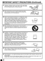
Cleaning--Unplug
the power cord from the AC outlet before
cleaning the product. Use a damp cloth to clean the product.
Do not use liquid cleaners or aerosol cleaners.
such as bathtub, washbasin, kitchen sink and laundry tub,
swimming pool and in a wet basement.
I I
not use the product near water,
•
Stand--Do not place the product on an unstable cart, stand,
tripod or table. Placing the product on an unstable base can
cause the product to fall, resulting in serious personal
injuries as well as damage to the product. Use only a cart,
stand, tripod, bracket or table recommended by the manufacturer or sold with the product. When mounting the product
on a wall, be sure to follow the manufacturer's instructions.
Use only the mounting hardware recommended by the
manufacturer.
•
When relocating the product placed on a cart, it must be
moved with utmost care. Sudden stops, excessive force and
uneven floor surface can cause the product to fall from the
cart.
•
Ventilation--The
vents and other openings in the cabinet are
designed for ventilation. Do not cover or block these vents
and openings since insufficient ventilation can cause overheating and/or shorten the life of the product. Do not place
the product on a bed, sofa, rug or other similar surface,
since they can block ventilation openings. This product is not
designed for built-in installation; do not place the product in
an enclosed place such as a bookcase or rack, unless
proper ventilation is provided or the manufacturer's instructions are followed.
•
The LCD panel used in this product is made of glass.
Therefore, it can break when the product is dropped or
applied with impact. Be careful not to be injured by broken
glass pieces in case the LCD panel breaks.
•
I
•
ill
Water and moisture--Do
o
'_ \ _ / z
Heat sources--Keep
the product away from heat sources
such as radiators, heaters, stoves and other heat-generating
products (including amplifiers).
The LCD panel is a very high technology product with 921,600 thin film transistors, giving you fine
picture details.
Occasionally, a few non-active pixels may appear on the screen as a fixed point of blue, green or red.
Please note that this does not affect the performance of your product.
IMPORTANT SAFETY PRECAUTIONS (Continued)
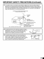
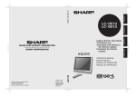
•
If an outside antenna is connected to the television equipment, be sure the antenna system is
grounded so as to provide some protection against voltage surges and built-up static charges.
Section 810 of the National Electrical Code provides information with respect to proper grounding
of the mast and supporting structure, grounding of the lead-in wire to an antenna discharge unit,
size of grounding conductors, location of antenna-discharge unit, connection to grounding electrodes, and requirements for the grounding electrode.
EXAMPLE OF ANTENNA
GROUNDING
AS PER
NATIONAL ELECTRICAL
CODE
LEAD IN
_CLAMP
_
GROUND
/7_.
NTENNA
WIRE
II
\\
DISCHARGEUNIT
I N Cv2ce
I !JLI
.
L_ _u .....
_-_-_1_
_ _/_
I L_ _
_
="
NEC--NATIONALELECTRICALCODE
•
•
(NEC SECTION
810-20)
GROUNDINGCONDUCTORS
{NEC SECTION810-21)
GROUNDCLAMPS
POWERSERVICEGROUNDING
ELECTRODESYSTEM
(NEC
ART 250, PART H)
lightning storm, or when it is left unattended and unused for
long periods of time, unplug it from the wall outlet and
disconnect the antenna. This will prevent damage to the
For
added protection
for thisand
television
equipment
equipment
due to lightning
power-line
surges. during a
An outside antenna system should not be located in the
vicinity of overhead power lines or other electric light or
power circuits, or where it can fall into such power lines or
circuits. When installing an outside antenna system, extreme
care should be taken to keep from touching such power
lines or circuits as contact with them might be fatal.
_
._
_
CONTENTS
DEAR SHARP CUSTOMER .............................................................................................................
IMPORTANT SAFETY PRECAUTIONS .......................................................................................
SUPPLIED ACCESSORIES .............................................................................................................
PREPARATION ............................................................................................................................
Using the Remote Control .........................................................................................................
Batteries for the Remote Control ..............................................................................................
Power Connection ......................................................................................................................
Antenna Connection .............................................................................................................
FRONT AND REAR CONTROL OPTIONS .............................................................................
Removing the Back Cover .......................................................................................................
Listening with Headphones .....................................................................................................
EZ SETUP .......................................................................................................................................
EZ SETUP during the First Power On ....................................................................................
REMOTE CONTROL ......................................................................................................................
BASIC OPERATION .................................................................................................................
Turning on POWER ...................................................................................................................
Switching TV/VIDEO [AVI/AV2/COMPONENT/TV]
Modes ...................................................
Sound Volume ...........................................................................................................................
8
8
9
9, 10
11-13
13
13
14
14
15
15-18
16
16
17
ON/OFF Standby .......................................................................................................................
Changing the Channels ............................................................................................................
SELECTING MENU ITEMS ............................................................................................................
17
18
19
Selecting Menu Items ..............................................................................................................
ADJUSTMENT ..........................................................................................................................
19
20-37
Adjusting the SLEEP TIMER Settings ....................................................................................
Adjusting the BRIGHTNESS Settings .....................................................................................
Adjusting the PICTURE FLIP Settings ...................................................................................
Adjusting the LANGUAGE Settings ........................................................................................
Adjusting the VIDEO ADJUST Settings ...........................................................................
Adjusting the PRESET Settings ..............................................................................................
SET UP .................................................................................................................................
Adjusting the BLUE SCREEN Settings ..................................................................................
Adjusting the CLOSED CAPTION Settings ......................................................................
Adjusting the V-CHIP Settings ..........................................................................................
CONNECTING WITH EXTERNAL DEVICES ..........................................................................
How to Fix the Cables ..............................................................................................................
TROUBLESHOOTING
..............................................................................................................
SPECIFICATIONS ...........................................................................................................................
DIMENSIONAL DRAWINGS ..........................................................................................................
m
Page
3
3-5
7
8-10
20
21
22
23
24, 25
26
27, 28
29
30, 31
32-37
38-40
40
41, 42
43
44
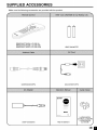
SUPPLIED
Make
ACCESSORIES
sure the following
accessories
RRMCGA077WJSA
RRMCGA077WJSB
RRMCGA077WJSC
are provided
(LC-20E1 U)
(LC-20E1 UI3)
(LC-20EIUW)
QCNWG0003CEPA
with the product.
UBATU0038CEZZ
QACCD3097CEPA
_,c pt
E
IIIN_
UADP-0243CEPZ
TINS-A158WJN1
LHLDW0109CESA
LC-20E1U,LC-20E1UW)
LHLDW0109CES8
(LC-20E1UB)
.2
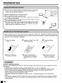
PREPARATION
•
Use
the remote
control
by pointing
it towards
the remote
sensor
window
r_
L_
window may preventproper operation.
--
Cautions regarding use of remote control
• Do
not expose
theObjects
remotebetween
control tothe
shock.
on the
main unit.
remote control and sensor
__
In addition, do not expose the remote control to liquid, and do not place
in an area with high humidity.
• Do net install or place the remote control under direct sunlight. The heat
may cause deformation of the unit.
• The remote control may not work properlyif the remote sensor window
of the main unit is under direct sunlight or strong lighting. In such case,
change the angle of the lighting or LCD TV set, or operate the remote
control closer to the remote sensor window.
POWER
indicator
Remote indicator
SLEEP
Sensor
Window
1
C__
J
Before using the LCD TV set for the first time, install two ("AAA" size, UM/SUM-4) batteries (supplied).
When the batteries become depleted and the remote control fails to operate, replace the batteries with
new ("AAA" size, UM/SUM-4) batteries.
1
Open the battery
cover.
• Slide the cover while
pressing the (_r) part,
2
Insert two ("AAA" size, UM/
SUM-4) batteries,
• Position the positive and
negative ends of the batteries
as indicated in the compartment.
3
Close the battery
cover.
• Engage the claw on the
cover into the battery
housing and slide shut.
J
Cautions regarding batteries
Improper use of batteries can result in chemical leakage and/or explosion. Be sure to follow the instructions below.
• Place batteries with their terminals corresponding to the (+) and (-) indications.
• Different types of batteries have different characteristics. Do not mix batteries of different types.
• Do not mix old and new batteries. Mixing old and new batteries can shorten the life of new
battery and/or cause the old battery to leak chemicals.
• Remove batteries when they become weak.
Chemicals that leak from batteries can cause a rash. If chemical leakage is found, wipe with a
cloth.
• The batteries supplied with the product may have a shorter life expectancy due to storage conditions.
• If the remote control will not be used for an extended period of time, remove the batteries from the
remote control.
m
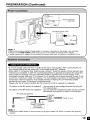
PREPARATION
(Continued)
Household power outlet
• Use a commercially available AC plug adapter, if necessary, depending on the design of the wall outlet.
• Always turn the MAIN POWER switch of the LCD TV set to off when connecting the AC adapter.
• Always unplug the AC adapter from the product and power outlet when not using for a long periodof time.
• A 75-ohm coaxial cable connector is built into the set for easy hookup. When connecting the 75ohm coaxial cable to the set, screw the 75-ohm cable to the ANT. terminal.
• Some cable TV companies offer "premium pay channels". Since the signals of these premium pay
channels are scrambled, a cable TV converteddescrambler
is generally provided to the subscriber
by the cable TV company. This converter/descrambler
is necessary for normal viewing of the
scrambled channels. (Set your TV to channel 3 or 4, typically one of these channels is used. If this
is unknown, consult your cable TV company.) For more specific instructions on installing cable TV,
consult your cable TV company. One possible method of utilizing the converteddescrambler
provided by your cable TV company is explained below.
Please note: An RF switch provided with two inputs (A and B) is required (not supplied).
"A" position on the RF switch (not supplied)
"B" position on the RF switch (not supplied)
: You can view all unscrambled channels by using the
TV's channel keys.
: You can view the scrambled channels via the converted
descrambler by using the converter's channel keys.
RF switch (not supplied)
_
Cable TV Line
Cable TV converter/[
descrambler
not supped
• Consult your SHARP Dealer or Service Center for the type of splitter, RF switch or combiner that might be
required.
J
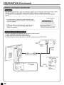
PREPARATION
(Continued)
• The antenna requirements for good color television reception are more important than those for black & white
television reception. For this reason, a good quality outdoor antenna is strongly recommended.
The following is a brief explanation of the type of connections that are provided with the various antenna
systems.
F-type connector
1. A 75-ohm system is generally a round cable with F-type
connector that can easily be attached to a terminal without
tools (not supplied).
75-ohm coaxial cable (round)
2. A 30g-ohm system is a flat "twin-lead" cable that can be
attached to a 75-ohm terminal through a 300-75-ohm
adapter (not supplied).
• Use one
A: Using
B: Using
• Connect
300-ohm twin-lead cable (flat)
of the following two diagrams if you connect an outdoor antenna.
a VHF/UHF combination outdoor antenna.
separate VHF and/or UHF outdoor antennas.
the outdoor antenna cable lead-in to the ANT. terminal on the rear of the TV set.
A. Combination
VHF/UHF Antenna
300/75-ohm
adapter
VHF/
HF
(n°t
VHF/UHF
s_PPkied)
antenna
tw_n._ead
300-ohm
{_
eeaxial ¢abke
I
75_ohm
Antenna cable (supplied)
B. Separate VHF and/or
UHF Antennas
UHF
antenn
a
VHF
Antenna input
terminal
\
7_ohm
J
m
FRONT AND REAR CONTROL OPTIONS
I Main unit (front view)
I
Upper control
panel
VOL (-)/(+)
OH (V)/(_)
MENU
TV/VIDEO
r_etca_nb_s
to an
angle between 12
degrees and 35 degrees.
The screen cannot be set
up straight. When
changing the angle, make
sure to hold the stand and
adjust the screen to the
best viewable angle.
Adjustable
range
Speaker
r
Remote
sensor
window
SLEEP indicator
The SLEEP indicator lights up red when
the SLEEP TIMER is set to on.
POWER indicator
A green indicator lights when the power is on and a red indicator lights
when in the standby mode the indicator will not light when the main
power is off).
• TV/VIDEO, CH (V)/(A), VOL (-)/(+), and MENU on the main unit have the same functions as the same buttons
on the remote control. Basically, this operation manual providesa description based on operation with the remote
control.
_
In
FRONT AND REAR CONTROL
I Main unit (rear view)
p /'
p /'
L /'
-----y
-----
OPTIONS (Continued)
I
VIDEO
AUDIO (L)
AUDIO (R)
PB
PR
AUDIO (L)
AUDIO (R)
- AV-IN2/OUT
t
COMPONEN1
Carrying handle
_-
VIDEOAUDIO (L)-AV-INI_ AUDIO (R)-L_ S-VIDEO|
HEADPHONEAntenna terminal-POWER INPUT-(DC 13V)
m
_
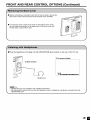
FRONT AND REAR CONTROL OPTIONS (Continued)
• Before connecting a connection cord into the rear terminal, remove the
back cover. Push in the tab and pull out the back cover carefully.
• To mount the cover, insert the 2 hooks on the bottom of the cover
into the cabinet and press on the upper part of the back cover until
the tab locks in place with a click.
==Plug the headphone
mini-plug into the HEADPHONE
jack located on the rear of the TV set.
•
•
On-screen
display
Rear terminal
VOLUME
60 IIIIIIIIIIIIIIIIIIIIIIIIIIIIIII
Headphones
• Headphones are not included in the supplied accessories.
• No sound will be heard from the main unit speakers when a headphone
HEADPHONE jack.
mini-plug is connected
into the
J
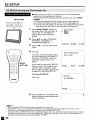
EZ SETUP
==When you turn on the TV for the first time, it will automatically
memorize the broadcasting channels.
Please perform the following instructions before you press MAIN
POWER.
(1) Insert the batteries into the remote control. (See page 8.)
(2) Connect the antenna cable to the TV set. (See page 10.)
(3) Connect the AC adapter to the DC input terminal of the product
and plug in the AC cord to the wall outlet. (See page 9.)
MAIN POWER
I
Press MAIN POWER, located on
the upper side of the main unit, to
turn on the TV. The SELECT
LANGUAGE mode will be displayed.
2
3
4
SELECTLANGUAGE
ENGLISH
ESPANOL
FRANCAIS
Press &/_' to select "ENGLISH",
"ESPANOL (SPANISH)" or
"FRANCAIS (FRENCH)".
SELECT:_
ENTER:_
EXIT:_
Press _1/1_ to access EZ SETUP
mode.
Press I_-.
CONNECT
ANTENNA
OR CABLE,
The tuner will automatically search
for the broadcasting and cable TV
channels. (The CH No. will automatically increase when it appears.)
NU/
If you want to stop the EZ SETUP
process once it has started, press
_1 and it will be canceled, tf you
want to SET UP again, please refer
to pages 27 and 28 on SET UP.
STARTEZ SETUP?
YES:_
UO:_
EXIT:_
To cancel EZ SETUP
PLEASEWAiT
Press _1.
AUTOPROGRA_ING
STOP:_
5
Once EZ SETUP is completed, the
lowest channel number memorized
will be displayed.
2
• Do not let the EZ SETUP screen display unattended for a long time.
• If EZ SETUP does not memorize aHthe channels in your region, please refer to pages 27 and 28 for more
informationon manually memorizing the channels using CHANNEL SETTING.
• It may be difficult to PRESET when the broadcasting signals are weak, the channel cycle frequency is incorrect or
the frequency jamming is occurring around the area. Please refer to pages 27 and 28 for more information on
manually memorizing channels using CHANNEL SETTING.
m
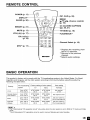
REMOTE CONTROL
FLIP (p. 22)
MENU/
/V/<I/I_
CC (CLOSED CAPTION)
(pp. 30, 31)
BRIGHT (p. 21)
MUTE (p. 17)
VOL(+)/(-)
(Cursor control)
rV/VlDEO
(p. 17)
(p. 16)
FLASHBACK .2
CR (A)/(V)
(p. 18)
--Channel
Select (p. 18)
MTS *s (p. 17)
.4 Displays the receiving channel for 10 seconds.
.2 Returns to the previous
channel.
*3Selects audio settings.
BASIC OPERATION
This product is factory set to comply with the TV broadcasting system in the United States. For Brazil,
Argentina and Uruguay, set the color system according to the country before using this product by
following the table below.
TV broadcasting
Country
Factory
system
setting
of color
TV
system
User
Video
setting
TV/Video
U.S.A.
Color: NTSC
TV ch: US ch
NTSC (N358)
US ch
NTSC (N358)
US ch
Not required
or N/A
Canada, Mexico,
Latin America
Color: NTSC
TV ch: US ch
NTSC (N358)
US ch
NTSC (N358)
US ch
Not required or N/A
Brazil
Color: PAL-M
TV ch: US ch
NTSC (N358)
US ch
NTSC (N358)
US ch
Set color system to
PAL_M (see page 25)
Argentina,
Uruguay
Color: PAL-N
TV ch: US ch
NTSC (N358)
US ch
NTSC (N358)
US ch
Set color system to
PAL-N (see page 25)
/
• The 3 Dimensional
mode.
*The
3 Dimensional
Y/C separation
Y/C separation
circuit*
circuit
only
works when
is used
to remove
the color
flickering
system
is set to N358
and color
bleeding.
in TV mode
and Video
BASIC OPERATION
(Continued)
1
Press
MAIN POWER
MAIN
the upper
on.
I
2
POWER,
side
The POWER
located
of the main
indicator
on
•
On-screen
display
unit, to
2
instantane-
ously changes
from red to green
and the main unit is turned on.
• The input mode indication
several seconds.
disappears
after
_STESEO <OHAI8
SAP
MOHO
POWER indicator
1
Turn on the power of the connected video equipment.
2
Press TV/VIDEO and select the
applicable input source. The
screen displays AV1, AV2, COMPONENT or TV mode each time
TV/VIDEO is pressed.
AV1 mode
!
AV2 mode
__/VIDEO
AV2
• The AV input mode indication
for 3 seconds.
•
•
remains
AVI:
Video equipment connected to the
AV1 input terminals.
An S-Video input terminal is
additionally provided for the AV1
COMPONENT
input. If both the S-Video terminal
and normal video terminals are
connected with cables, the SVideo input terminal takes priority.
AV2:AV2
mode is used to adjust the
preset settings and IN or OUT
can be selected. AV2 indication is
not displayed when OUT is
selected. (For details on setting
AV2-1N/OUT, see page 26.)
• COMPONENT:
Video equipment connected to the
COMPONENT input terminals.
m
!
mode
COMPONENT
!
TV mode
12
m
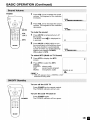
BASIC OPERATION
POWER
(Continued)
Press VOL (+) to increase the sound
volume. The segment of the indicator
increases.
VOLUME
50 IIIIIIIIIIIIIIIIIIIIIIIIII
2
.....
Press VOL (-) to decrease the sound
volume. The segment of the indicator
decreases.
VOLUME
19 llllll
.........................
To mute the sound
_ _
(+)/(-)
_
MTS
_
Press MUTE to temporarily turn off
the sound.
The MUTE mark_(is
displayed for
4 seconds.
2
Press MUTE or VOL (+)/(-) to turn
the sound back to the previous level.
The mute function is automatically
turned off when any of the following
buttons are pressed: POWER,
VOL (+)/(-) or MTS.
To select
1
MTS
(Multi
VOLUME
30 IllllllllllllllI
ch TV Sound)
Press MTS to display the MTS
2
screen.
2
Press MTS
settings.
STEREO:
SAP:
MONO:
to select the MTS
stereo audio
second audio program
monophonic audio
_STEREO <ONAIR
SAP
_NO
• <ON AIR appears when a STEREO or SAP
broadcast is being aired.
To turn off the LCD TV
Press POWER on the remote control.
The POWER indicator will turn red.
To turn the LCD TV back on
POWER
...............
Press POWER again.
The POWER indicator will turn green.
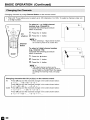
BASIC OPERATION
(Continued)
Changing channels by using Channel
Select on the remote control
or 3-digit
I • This
LCD number.
TV set allows you to select up to 125 channels (1 to 125). To select a channel, enter a 2-
0-]
To select a 1- or 2-digit channel
number (e.g., Channel 5):
Complete the following procedure
within 4 seconds.
_CH
1
Press the _
button.
2
Press the _
button.
• When selecting a 1-digit channel number,
do not fail to press the _ button first.
-
C;/e_t el
To select a 3-digit channel number
(e.g., Channel 115):
Complete the following procedure
within 4 seconds.
W
1
Press the _
button.
2
Press the _
button.
3
Press the _
button.
• The 3-digit channel number can be
selected only when the receiving mode is
set to CABLE in CH-SETTING. (For details
on setting the receiving mode, see page
27.)
Changing
Air
channels
Press CH (A)
with
OH (_)/(v)
and the channels
on the
change
control
in the order shown
below:
in the order shown
below:
Press CH (A) and the channels change in the order shown
1 -e 2-_ 3-_,,.
-e 125-el
-e 2 =e 3-e.,
,
below:
Press
below:
2-e3-_,,,-_68-e69-e2-->3-e
..
Press CH (v) and the channels
3-e 2-_ 69-e 68-e...-e
3->
Cable
remote
CH (v)
3->2-->1
and the channels
-e 125-e...-e
3-e
change
2-e...
change
2-_
in the order shown
1 -e,,.
\
']11115
SELECTING
MENU ITEMS
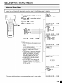
• This LCD TV set allows you to adjust the various settings using the menu screen. Select
menu item by following the steps below and then refer to the indicated page for details.
the desired
(Page 20)
1
2
Press MENU to display the MENU
screen.
Press A/V to select the desired
menu item.
3
Press _1/1_ to enter.
4
Press MENU to exit.
[]SLEEP TIMER
eRErt_tt
SLEEP TIMERI---
REMAINI
___
SIELE_T:@
iID,_tIST:@
EXIT:_
(Pages 24, 25)
[_
MENU
[_?[]SLEEPTIMER >
[]VIDEO ADJUST
[]PRESET
[]CLOSED CAPTiOH>
IV-CHIP BLOCK
[]SET UP
[]VIDEO AD_UST{TV)
ORET_
PICTURE
I
301 _
TIHT
I
Ol _
BLACKLEVEL I
01_
SP*ARPNESS I
01_
COLORSYSTEMI N3581_
RESET
SELE_T:_
EXTER:@
EXIT:_)
(Pages 21, 22 and 26)
[_
SELECT:@
EHTER:@
EXIT:_
• The TINT display only appears when
the color system is sat to N358 or
N443.
• The displayed items differ depending
on the setting conditions.
• The selected item changes to yellow.
• Items in magenta cannot be selected.
• This product is factory set to comply
with the color system in the United
States (NTSC-N358). For Brazil
(PAL-M), Argentina (PAL-N) and
Uruguay (PAL-N), set the color
system before using this product.
• To return to the previous screen,
select RETURN.
• You can adjust some settings with
the special buttons: CC, PIC. FLIP,
SLEEP and BRIGHT (see pages 20,
21, 22 and 30).
[_PRESET
ORET_N
BRIGHTNESS
AgTO_
8FF
_ICTURE FLIP
AV2 I_/o_r
SELECT:@
ISRIGHT]
IOFF
]
INORMAL]
IIH
J
_SST:@
EXIT:_
(Page 31)
[_
ORET_N
C_/TEXT IOFF}
SIELE_T:_
_SST:_
EXIT:_
(Pages 34-37)
IHPST SECRETNO.
EXIT:_
(Pages 23, 27-29)
_SET _
IDRET_N
BLUESCREEH[OFFI
L_H_J_GE
CB-SETTIHG_
* The screen indications
shown above are larger than actual for easy reading.
SELECT:@
_SST:@
EXIT:_
ADJUSTMENT
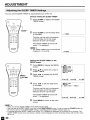
You can set the SLEEP TIMER to automatically
turn off the TV.
Directly setting the SLEEP TIMER
1
Press SLEEP to display the SLEEP
TIMER screen.
2
Press SLEEP to set the sleep timer
(in minutes).
_!LEEP
---
REMAIN
The time can be set in increments
of 30 minutes and in the range
between 30 and 120 minutes.
0(_
The SLEEP TIMER is turned off
when --- is displayed.
W
• The SLEEP TIMER screen automatically
disappears in 3 seconds.
..._J
60 REMAIN
Setting the SLEEP TIMER on the
MENU screen
1
0 0 0 0
MENU/
AIVI<Ib_
Press MENU to display the MENU
screen.
2
Press A/V to move the cursor to
SLEEP TIMER.
3
Press </_- to display the SLEEP
TIMER screen.
MENU
_[]SLEEP TtMER
[]VIDEO ADJUST
[]PRESET
[CLOSEO CAPTION_
[]R-CHIP BLOCK
[]SET UP
SELECT:_
4
Press _1/1_to set the sleep timer
(in minutes).
ENTER:@
EXIT:_
[i_SLEEPTtMER
_RETURO
BLEEPTIMER J--- REMAIN]
The time can be set in increments
of 30 minutes and in the range
between 30 and 120 minutes.
The SLEEP TIMER is turned off
when --- is displayed.
SELECT:_
5
ADJUST:_
EXIT:_
Press MENU to return to the main
screen.
• When you set the SLEEP TIMER, the SLEEP indicator lights.
• After you set the SLEEP TIMER, if you turn off the MAIN POWER on the TV set or press the POWER button on
the remote control, the SLEEP TIMER setting is cancelled and the SLEEP indicator goes out.
• 5 minutes before the SLEEP TIMER turns off the TV, 5 REMAIN is displayed on the screen for 4 seconds. The
SLEEP TIMER counts down and shows a similar 4-second display for each remaining minute until the timer turns
off the TV.
m
ADJUSTMENT
You can set the brightness
(Continued)
of the screen.
Directly setting the BRIGHTNESS
1
Press BRIGHT to display the
BRIGHTNESS screen.
2
Press BRIGHT to change the
setting.
_BRIGHT_NORMAL_
DARK"
BRIGHTNESS
[BRIGHT]
L_ @_ II
• The BRIGHTNESS screen automatically
disappears in 3 seconds,
• [BRIGHT]: maximum brightness
[NORMAL]: 60% brightness (suitable for
viewing in a welMit area and saves
energy)
[DARK]: 10% brightness (sufficiently bright
when viewing in a dimly lit area)
BRIGHT
Setting the BRIGHTNESS
MENU screen
1
on the
Press MENU to display the MENU
screen.
2 Press,,/, tomove
the cursor to
PRESET.
3
o o o o
t
Press <1/1_ to enter.
MENU
[!_SLEEPTIMER
[]VIDEO ADJUST
_[PREEET
[CLOSEN CAPT]ON_
_]V-CHIP BLOCK
[]SET UP
MENU/
SELECT:@
c_ @N@N
@@o@o
@o @N@8
4
Press &/V to move the cursor to
BRIGHTNESS.
5
Press _1/_- to set the brightness.
6
Press MENU to return to the main
screen.
ENTER:@
[]PRESET
[]RETURN
[_ BRIGHTNESS
AUTOPOWEROFF
PICTUREFLIP
AVE IN/OUT
SELECT:@
EXIT:÷
[BRIGHT]
[OFF
]
fNORMAL]
[IN
]
ADJUST:@
EXIT:_
ADJUSTMENT
(Continued)
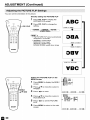
You can set the orientation of the picture.
Directly setting the PICTURE FLIP
PIG
1
Press PIC. FLIP to display the
PICTURE FLIP screen.
2
Press PIC. FLIP to change the
setting.
FLIP
ABC
_URE
/7=
FLIP
.
[NO_r_AL1
NORMAL_UPSIDEDOWN÷
MIRROR_ ROTATE
• The PICTURE FLiP screen automatically
disappears in 3 seconds.
• [NORMAL]: normal image
[MIRROR]: mirror image
[ROTATE]: rotated image
[UPSIDE DOWN]: upside down image
08A
w
08V
VBC "
Setting the PICTURE FLIP on the
MENU screen
1
0000
MENU/
&ITI411_
Press MENU to display the MENU
screen.
2
Press &/T
PRESET.
to movethe
3
Press _/_
to enter.
cursorto
v
(z} 80 (30
(4) 81) (e)
Go Go (3o
W
4
MENU
_NLEEP TIMER
_V[DEO AOJUST
[_PRESET
_CLOSED CAPTIOH
_
_V-CNIP 8LUCK
_SET UP
Press &/Y to move the cursor to
PICTURE FLIP.
5
Press <1/1_ to set the PICTURE
FLIP.
6
Press MENU to return to the main
screen.
SELECT:_
ENTER:_
_PRESET
ORETURH
8_IGHTHESS
AUTOPOWER
OFF
PICTURE FLIP
AV2 IH/OUT
SELECT:®
EXIT:_
{BRIGHT)
{OFF I
[HORMAL]
{IN
J
AOJUST:®
EXIT:÷
ADJUSTMENT
(Continued)
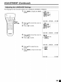
The language for the On-Screen
Display can be ENGLISH, SPANISH or FRENCH.
1
Press MENU to display the MENU
screen.
MENU
[_7[KLEEP TtMER
[]VIDEO ADJUST
[]PRESET
[CLOSEO CAPT]ON_
_]V-CHIP BLOCK
[]SET UP
_NU/
SELECT:_
"<CC_--
TI,I_
2
Press A/V
SET UP.
to move the cursor to
3
Press _1/_- to enter.
Press A/V to move the cursor to
LANGUAGE.
5
Press _1/_- to enter.
7
Press A/V
guage.
to select the lan-
Press MENU to return to the main
screen.
E_TER:_
EXIT:_
_SET UP
QRETgRO
8LUE SCREENfOFFI
LANGUAGE
OH-SETTING_
SELEOT:_
6
EXIT:_
_EOO
[]SLEEP TIMER
[VIOEO ADJUST
[]PRESET
[]CLOSED CAPTION_
_V-CH[P 8LOB
_[SET
UP
SELECT:_
4
ENTER:_
E_TER:_
EXIT:_
LAOGUAGE
EOGLISH
ESPANOL
FEANCAIS
SELECT:_
EXIT:_
ADJUSTMENT
(Continued)
1
Press MENU to display the MENU
screen.
MENU
[_?[]NLEEPTIMER >
[VIDEO AUJUST
[]PRESET
[]CLOSED CAPTiON_
[V-CNIP 8LOCK
[]SET UP
SELECT:@
_NU/
TI<I_
2
Press A/Y to move the cursor to
VIDEO ADJUST.
3
Press </1_ to enter.
EHTER:@
MENU
[]SLEEP TIMER
E_[]VIDEO AUJUST
[]PRESET
[]CLOSED CAPTION
_
_IV-CNIP 8LOCK
[]SET UP
SELECT:@
4
5
Press A/V to move the cursor to
the desired item.
Press </1_ to enter.
EHTER:@
•
7
EHTER:@
EXIT:_
Press </1_ to change the setting.
See
page
25 for the settings.
Press MENU to return to the main
screen.
[RETURR
PICTURE
30
÷
-
SELECT:@
m
EXIT:_
[]VIDEO AUJUST(TD)
_RETURN
PICTURE
[
30}_
TLNT
[
O]_
COLOR
[
O]_
SLACKLEVEL [
O]_
SHARPNESS [
O]_
COLORSYSTEM[ NS5N}_
RESET
ELECT:@
6
EXIT:_
ADJUST:@
EXIT:_
ADJUSTMENT
(Continued)
TV mode
PICTURE
Decrease contrast
Increase contrast
TINT
Toward purple
Toward green
COLOR
Lower color intensity
BLACK LEVEL
Less brightness
SHARPNESS
Soft picture
COLOR SYSTEM
.......................
_
.......................
_
Higher color intensity
More brightness
......................
_........................ Sharp picture
N358 _ PAL-M "," PAL-N *-]
J
AV mode
PICTURE
Decrease contrast
_
Increase contrast
TINT
Toward purple
Toward green
COLOR
Lower color intensity
Higher color intensity
BLACK LEVEL
Less brightness
......................
_........................ More brightness
SHARPNESS
Soft picture
......................
_........................ Sharp picture
RED-BLUE
Stronger red
GREEN
Weaker green
COLOR SYSTEM
Press _1/1_ to select the COLOR SYSTEM.
Stronger blue
.......................
;....................... Stronger green
_, N358 _ N443 _ PAL _ PAL-M _ PAL-N _ SECAM _ PAL60
• When the COMPONENT
r" NTSC _ PAL*_
mode is selected:
/
•
•
•
•
TINT is displayed only when N358 or N443 is selected.
In BLUE SCREEN, VIDEO ADJUST settings displayed in magenta cannot be selected.
Selecting RESET will return all settings to the factory settings. (See page 24.)
TV mode
This productis factory set to comply with the color system in the United States (NTSC-N358). For Brazil (PALM), Argentina (PAL-N) or Uruguay (PAL-N), adjust the color system before using this product.
ADJUSTMENT
(Continued)
1
Press MENU to display the MENU
screen.
MENU
_[SLEEP TIMER
[]VIDEO ADJUST
[]PRESET
[CLOSEO CAPTION_
I_Iv-cHIP BLOCK
[]SET UP
SELECT:@
2
3
Press A/_'
PRESET.
to move the cursor to
Press </,
to enter.
4
5
6
Press A/V to move the cursor to
the desired item.
Press </1_ to change the setting.
[BRIGHT]
PICTURE
FLIP
Maximum
brightness
AV2 IN/OUT
[OFF]
]NORMAL]
[IN]
[NORMAL]
[ON]
{BRIGHT)
{OFF I
[OOBMAL]
{IN
J
Normal image
ofienta_on
AOJUST:@
EXIT:_
Brightness 60% --_ Suitable for viewing in a weN*lit area.
Saves energy.
Bdghtness t0% --_ Sufficiently bdght when
viewing in a dimly Nt area.
[OFF]
The power of the LCD TV set is turned off when there is
no signal for 5 minutes.
This feature is inactive.
[MIRROR]
Mirror image --> To display mirror images for special uses.
[ROTATE]
Rotated image --> To display rotated images for special
uses.
[UPSIDE
DOWN]
[OUT I_
] Line Output is selected, Output volume is fixed, Speaker
output is available.
] Line Output is selected, Output volume is variable,
[OUT I_
Upside down image --> TO display images
down for special uses.
Speaker
m
EXIT:_
Press MENU to return to the main
screen.
[DARK]
AUTO POWER OFF
(only TV mode)
ENTER:@
[]PRESET
QRETURH
8RIGHTHESS
AgTOPOWEROFF
PICTUSEFLIP
AV2 IN/OUT
SELECT:@
BRIGHTNESS
EXIT:_
MENU
[]SLEEP TIMER
[]VIDEO ADJUST
_[PRESET
[CLOSEO CAPTION_
I_Iv-cHIP BLOCK
[]SET UP
SELECT:@
w
ENTER:@
output is Mute.
upside
._
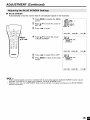
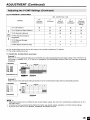
ADJUSTMENT
•
CHANNEL
(Continued)
SETTING
It is necessary to set the receiving mode to AIR or CABLE channels to receive locally broadcast TV
programs.
1
Press MENU to display the MENU
screen.
2
Press A/V
SET UP.
3
Press _1/_- to enter.
to move the cursor to
MENU
[SLEEP TtMER
[]VIDEO ADJUST
[]PRESET
[]CLOSEO CAPT]ON_
i'_IV-CHIP BLOCK
_[SET
UP
_ENU/
SELECT:_
AITI,I,
4
5
Press A/_' to move the cursor to
CH-SETTING.
Press _1/1_ to enter.
7
Press A/V to move the cursor to
AIR/CABLE.
Press _1/1_ to enter.
9
Press A/_' to move the cursor to
the desired mode.
ENTER:_
EXIT:÷
Press MENU to return to the main
screen.
• Receivable channels of your TV set are:
VHF: 2 through 13.
UHF: 14 through 69.
EXIT:_
AIR/CABLE
AIR
CABLE
SELEUT:_
AIR channels:
ENTER:_
CH-GETT[NG
ONETURN
AIN/CAOLE_
CH SEARCH_
CHMEt_ONY_
ELECT:_
8
EXIT:÷
[]SET UP
ORETURN
BLUESCREEN[OFF]
LANGUAGE
CN-SETTINO_
ELECT:_
6
ENTER:_
CABLE channels:
1 (HRC and JRC mode only)
2 through 125 (STD, HRC and IRC)
EXIT:÷
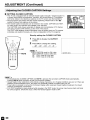
ADJUSTMENT
•
(Continued)
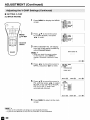
Saving broadcast TV channels in the memory
1
2
_ENU/
3
AIVI<I•
4
Press MENU to display the MENU
screen, press A/Y to move the
cursor to SET UP, and press <1/•
to enter.
Press A/Y to move the cursor to
CH-SETTING, and press <1/• to
enter.
Press A/Y to move the cursor to
CH SEARCH, and press <1/• to
enter.
ORETURN
AIR/CASLE_
CH SEARCH_
[Z_ CHMEI_ORY_
CH-SETTING
Press •. The tuner will search
through all available channels in
your area and add them to the
TV's memory.
CH SEARCH
AiR
• To interrupt CH SEARCH, press <1.
CH SEARCH will stop at the current
channel end will not add any higher
channels.
5
•
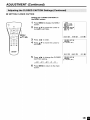
Adding
weak
or additional
2
3
0 0 0 0
*_'_'_
_i./
.i./
L J
G,_5q _
MENU/
AlYI<II•
Channel
Select
4
5
6
START:@
EXIT:_
Press MENU to exit.
channels
1
2
or erasing
unwanted
channels
Press MENU to display the MENU
screen, press &/V to move the
cursor to SET UP, and press <1/•
to enter.
from
TV memory
CH-SETTIHG
ORETURN
AIR/CA8LE_
CH SEARCH_
[_
Press A/Y to move the cursor to
CH-SETTING, and press <1/• to
enter.
CHMEI_OSY_
CHMEMORY
Press A/Y to move the cursor to
CH MEMORY, and press <1/• to
enter.
AI8
2
Use A/_' or Channel Select to
select each desired channel to add
or erase.
Press • to add the channel to the
TV's memory or press • to erase
the channel from the TV's memory.
EXIT:_
TO AO0:@
•
to add channel 2
to the TV memory
Press MENU to exit.
to erase chai/nel 2
from the TV memory
CHMEMORY
SPMM_
AIR
2
TO ERASE:@
• If CH SEARCH is performed again, the previously
[.
memorized
channels will be lost,
EXIT:_
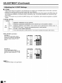
ADJUSTMENT
•
(Continued)
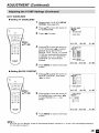
BLUE SCREEN
Automatically turns the screen blue if a broadcast signal is not received.
1
Press MENU to display the MENU
screen.
2
Press A/V
SET UP.
3
Press _1/1_ to enter.
to move the cursor to
_EHU
[]SLEEP TIMER
[VIOEO ADJUST
[]PRESET
[]CLOSED CAPTION_
r_V-CH[P 8LOCK
_[SET UP
SELECT:@
_ENU/
4
AITI_I_
Press A/V to move the cursor
to BLUE SCREEN.
6
Press _1/1_ to select ON or OFF.
Press MENU to return to the main
screen.
ERIT:_
[]SET UP
_RETgRR
BLUE SCREENfOFEI
LARGRAGE
CH-SETTING_
SELECT:@
5
ERTER:@
_7
ARJUST:@
EXIT:÷
[]SET UP
[RETgRR
BLUE SCREERfOR ]
LARGRAGE
CH-SETTING_
SELECT:@
ARJUST:@
EXIT:_
• When received signals are weak or interfered with by some other signals, the BLUE SCREEN function may be
activated. To watch the TV under such conditions, set BLUE SCREEN to OFF.
• When the AV-1, AV-2 or COMPONENT input mode is selected, if no signal is being input, the BLUE SCREEN
function is activated.
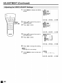
ADJUSTMENT
(Continued)
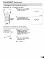
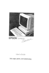
• SETTING CLOSED CAPTION
• This TV set is equipped with an internal Closed Caption decoder. "Closed Caption" is
a system which allows conversations, narration, and sound effects in TV programs
and home videos to be viewed as captions on the TV screen (see the illustration).
• Not all programs and videos will offer closed captioning. Please look for the "_'
symbol to ensure that captions will be shown.
• The Closed Caption broadcasts can be viewed in two modes: CAPTION and TEXT.
For each mode, two channels are available: OH1 and OH2.
The CAPTION mode shows subscripts of dialogs and commentaries of TV dramas
and news programs while allowing a clear view of the picture.
The TEXT mode displays various information over the picture (such as TV program
schedules and weather forecasts, etc.) that is independent of the TV programs.
Directly
1
Press
F*
0o (]o
6o G,} (]_
M UTE
the CLOSED
CAPTION
Press CC to display the CC/TEXT
screen.
2
_
setting
CC to change
OFF_
• COl:
002:
TI:
1"2:
CCl_CC
the setting.
2_T1_T2_
CAPTION mode
CAPTION mode
TEXT mode for
TEXT mode for
for CH1 data
for CH2 data
CH1 data
CH2 data
CC/TEXT {CCt]
• If a broadcast has CLOSED CAPTION and MUTE is pressed, the set enters CAPTION mode automatically.
Pressing MUTE again will return the set to its previous condition.
• Closed Caption may malfunction (white blocks, strange characters etc.) if signal conditions are poor or if there are
problems at the broadcast source. This does not necessarily indicate e problem with your set.
• If any button is pressed to call up the On-Screen Display while viewing a Closed Caption broadcast, the closed
captions will disappear momentarily.
• If no TEXT broadcast is being received while viewing in the TEXT mode, the screen may become dark and blank
for some programs. Should this occur, switch the Closed Caption mode to OFF.
ADJUSTMENT
•
(Continued)
SETTING CLOSED CAPTION
Setting the CLOSED CAPTION on
the MENU screen
1
2
!
Press MENU to display the MENU
screen.
Press A/_' to move the cursor to
CLOSED CAPTION.
MENU
[_SLEEP TIMER
[]VIREO ADJUST
[]PRESET
_[CLOSED CAPTION_
r_[-CHIP 8LOCK
[]SET UP
MENU,
3
4
SELECT:@
Press <1/_- to enter.
Press A/V
CC/TEXT.
ENTER:@
EXIT:_
[]CLOSER CAPTION
[RETgRN
CC/TEXT {OFF]
to move the cursor to
W
ELECT:@
5
Press <1/_- to change the CLOSED
CAPTION setting.
_
6
OFF_CC
Press
screen.
MENU
I_CC
2_Tl_T2_
to return
to the main
I
ADJUST:@
_]CLOSEOCAPTION
[]RETURN
[_
CC/TEXT fOEEI
EXIT:_
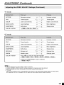
ADJUSTMENT
•
(Continued)
V-CHIP
• This function allows TV programs to be
children from watching violent or sexual
• Restriction of TV programs includes two
the TV Parental Guidelines. The MPAA
and content.
restricted and TV usage to be controlled based on FCC data. it prevents
scenes that may be harmful.
ratings that contain information about the program: the MPAA rating and
rating is restricted by age. TV Parental Guidelines are restricted by age
• Since a TV program may use either the MPAA rating or the TV Guidelines,
control.
both should be adjusted for complete
[1] MPAA RATING
RATING
G
GENERAL AUDIENCES.
PG
PARENTAL GUIDANCE
age
PG-13
PARENTS STRONGLY CAUTIONED.
base
R
RESTRICTED.
NC-17
NO ONE 17 AND UNDER ADMITTED.
X
X is an older rating that is unified with NC-17 but may be encoded in the data of older movies.
MPAA
RATING
All ages admitted.
SUGGESTED.
Some material may not be suitable for children.
Some material may be inappropriate
Under 17 requires accompanying
(examples)
Example 1:
PG-13 in the age-based rating is
blocked, this will also automatically
block the higher ratings R, NC-17
and X.
1. Usersettlng
BLOCK
Example 2:
R in the age-based rating is
blocked, this will also automatically
block the higher ratings NC-17 and
X.
1. User setting
BL_K
• The MPAA rating is only age-based.
m
for children under 13.
parent or adult guardian.
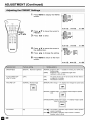
ADJUSTMENT
(Continued)
[2] TV PARENTAL GUIDELINES
<:::::: content base :_
FV
V
(Fantasy
Violence)
(Violence)
(Sexual
Situation)
(Adult
Language)
(Sexually
Suggestive
Dialog)
TV-Y (All children)
[]
[]
[]
[]
[]
[]
[]
TV-Y7 (Direct to Older Children)
TV-G (General Audience)
X
[]
[]
[]
[]
X
X
RATING
"[
age
base
TV-PG (Parental Guidance
U-
S
L
Suggested)
TV-14 (Parents Strongly
Cautioned)
X
X
X
X
TV-MA (Mature Audience Only)
X
X
X
D
[]
[]
X
X
[]: The content rating can be set, but this rating is not normally broadcast by TV stations
X: The content rating can be set
TV PARENTAL
GUIDELINES
(examples)
Example 1:
When TV-Y7 in the age-based rating is set to BLOCK, this will automatically block the higher ratings: TV-G, TV-PG, TV-14
and TV-MA In addition, D, L, S, V and FV in CONTENT are automatically blocked unless you manually set BLOCK
CONTENT
1. Uut rotting
T,_.y
_. Block table
mu
....
Example 2:
When no item in the age-based rating is blocked, D in the content-based
1. IJur letting
rating will be automatically
blocked
2. BlOCk table
¢m, tmt bKe
T_y
F't
--m
$
TV.y
_ZZZ
_t.V7
W-G
W-14
W.MA
• Age-based ratings can be modified by the content-based ratings, but only in the combinations indicated by an X in
the table above
• Choosing a lower age-based rating blocks the higher age-based ratings regardless of content rating settings
• If you set TV-Y and TV-Y7 to BLOCK, CONTENT will display all items
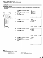
ADJUSTMENT
(Continued)
• SETTING V-CHIP
[1] MPAA RATING
1
Press MENU to display the MENU
screen.
MEOO TIMER
_[SLEEP
[]VIDEO ADJUST
[]PRESET
[]CLOSED CAPTIOU_
IT'D-CHIP 8LOCK
[]SET UP
ENU/
AI,I<II_
2
Press &/V to move the cursor
to V-CHIP BLOCK, and press
<1/_- to enter.
MENU TIMER
[]SLEEP
[]VIDEO ADJUST
[]PRESET
[]CLOSED CAPT]OH_
[_iI_Iv-cHIP BLOCK
[]SET UP
_
Select
Channel
3
INPUT SECRET NO. will display.
Input the 4-digit secret number by
using Channel Select.
IOPUT SECRET NO,
• When you inputthe secret number
for the first time, press MENU to
register. Otherwise, continue to step
4.
EXIT:@
4
Press <1/_- to move the cursor to
MPAA, and press <1/_- to enter.
IV-CHiP BLOCK
ORETURU
[_ MPAA
TU GOIDELiNES_
STATOS{OFF]
SELECT:@
5
Press &/V to move the cursor to
PC, and then press <1/_- to select
BLOCK. If you set PG to BLOCK,
PC-13, R, NC-17 and X are
automatically blocked.
Press MENU to return to the main
screen.
• If you set G to BLOCK, all ratings are automatically blocked.
• If you set X to BLOCK, G, PG, PG-13, R and NC-17 are not blocked.
EXIT:@
WAA
ORETURN
G
{..... I
[_ PG
{BLOCK]
PG-13 {BLOCK]
R
{BLOCK]
NC-17 [BLOCK]
X
[SLOCK]
SELECT:@
6
ENTER:@
ADJUST:@
EXIT:@
ADJUSTMENT
(Continued)
[2] TV GUIDELINES
• Setting TV GUIDELINES
1
Repeat steps 1 to 3 of [1] MPAA
RATING. (See page 34.)
2
Press A/V to move the cursor to
TV GUIDELINES.
3
Press _1/_- to enter.
_]V-CHIP 8LOCK
_NETURN
MPAA
C_ TV GUIOELiNES_
STATUS[OFF]
_ENU/
SELECT:_
AITI,I,
4
5
•
Setting
BLOCK
Press A/V to move the cursor to
TV-Y7, and press _1/_- to select
BLOCK. If you set TV-Y7 to
BLOCK, TV-G, TV-PG, TV-14 and
TV-MA are automatically blocked.
In addition, D, L, S, V and FV in
CONTENT are automatically
blocked.
ENTE8:_
EXiT:_
TU GUIOELIHES
QNETURN
TV-Y [ ..... I
TV-YT [8LOCK]
TV-G [BLOCK]
TV-PG [8LOCK]
TV-14 [BLOCK]
TV-MA [8LOCK]
8LOCKCONTENT>
tO L S V FV]
SELECT:_
ADJNST:_
EXlT:_
Press MENU to return to the main
screen.
CONTENT
1
Press A/V to move the cursor to
BLOCK CONTENT, and press
_1/1_ to enter.
TU GUIOELIHES
QNETURN
TV-Y [-----[
TV-YT [-----]
TV-G I-----[
TV-PG I-----]
TV-14 I-----[
TV-MA I-----[
[_ 8LOCK
CONTENT>
f
_ENU/
SELECT:_
AklVl4III_
2
Press A/Y to move the cursor to
the desired item, and press _l/_to select BLOCK or ..... (unblock).
EXIT:_
8LOCK
CONTENT
_NETURN
D [-----]
L [NLOCSI
S [-----I
V [-----I
FV [-----I
SELECT:_
3
ENTEN:_
ADJNST:_
EXIT:_
Press MENU to return to the main
screen.
• if you set TV-14 to BLOCK, TV-MA is automatically blocked. Contents D, L, S and V are automatically blocked by
X in the table on page 33.
ADJUSTMENT
(Continued)
[3] ACTIVATING V-CHIP BLOCK
• Setting STATUS
You can activate V-CHIP BLOCK after setting [1] MPAA RATING and/
or [2] TV GUIDELINES.
1
Repeat steps 1 to 3 of [1] MPAA
RATING.
BTIv-cHIp BLOCK
ORETUR_
MPAA
TV GgIHELIHES_
BTATgS{ONI
2
0000
MENU/
AITI<II_
Channel
Select
3
to move the cursor to
ELECT:_
E_TEN:_
EXIT:÷
Press </1_ to set STATUS to ON.
• If STATUS is set to OFF, V-CHIP
BLOCK will not be activated.
4
[4] CANCELING
Press A/_'
STATUS.
Press MENU to return to the main
screen.
THE V-CHIP BLOCK SCREEN WHILE V-CHIP BLOCK IS ACTIVATED
V-CHIP HAS BEEN ACTIVATED
appears if you watch a program
with the same Program Rating
data you configured.
B-CHIP HAS BEENACTIVATED
TB-Y
MENU
• V-CHiP HAS BEEN ACTIVATED will
not be displayed if STATUS is not
configured to ON.
2
Channel
Select
3
Press MENU to display INPUT
SECRET NO.
Input the 4-digit secret number by
using Channel Select; V-CHIP
BLOCK is temporarily canceled. If
you input an incorrect secret
number, SECRET NO. IS INCORRECT is displayed. In this case,
input the correct secret number.
I_PDT SECRET HO,
• If you turn the poweron from off, V-CHIP BLOCK will be activated again.
• If you select V-CHIP BLOCK again by using MENU, V-CHIP BLOCK will be turned on again.
m
EXIT:_
ADJUSTMENT
[5] CHANGING
(Continued)
THE V-CHIP BLOCK SETTINGS
1
Repeat steps 1 to 2 of [1] MPAA
RATING, then INPUT SECRET
NO. will be displayed.
INPUT SECRET nO,
£XIT:_
2
Channel
Select
Input the 4-digit secret number by
using Channel Select; the VCHIP select mode will be displayed. Set V-CHIP BLOCK again.
INPUT SECRET nO,
EXIT:_
[6] CHANGING
OR CLEARING
THE SECRET NUMBER
If you forgetthe secret number,clear the secret number as follows.
1
Upper control panel
of the main unit
--
VOL '4"
V
CH A
MENU
CH (A)
Repeat steps 1 to 2 of [1] MPAA
RATING, or 1 to 2 of [4]
CANCELING THE V-CHIP
BLOCK SCREEN WHILE V-CHIP
BLOCK IS ACTIVATED, then
INPUT SECRET NO. will be
displayed.
2
Press and hold both OH (^) and
VOL (+) on the TV set simultaneously until the message INPUT
SECRET NO. blinks.
VOL (+)
MENU
3
Press MENU to exit.
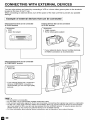
CONNECTING
WITH EXTERNAL
DEVICES
You can enjoy picture and sound by connecting a VCR or a home video game system to the terminals
located on the rear of the TV set.
When connecting an external device, turn off the power of the main unit first to prevent any possible
damage.
I Example
of external
devices
External devices that can be connected
to AV4N2 terminal
that can be connected
I
External devices that can be connected
to AV-INt terminal
f<Example>
• VCR
• Laser disc player
<Example>
• Video camera
• Home
video
game
system
* If your external device has an S-Video terminal,
S-VIDEO connection is recommended.
External devices that can be connected
to COMPONENT terminal
F_
<Example>
• DVD, etc.
-%
If your external device has a component
terminal, COMPONENT connection is
recommended (you can view high-quality
pictures).
•
•
•
•
PC connection is not possible.
For the cable, use a commercially available audio/video cable.
Only connect audio/video signals to AV-IN1 and 2 terminals. Connecting other signals may result in a malfunction.
AV-IN1 has 2 video input terminals: VIDEO and S-VIDEO. When you connect external devices to both terminals
(and if you select AV-IN1), you can only view pictures from the S-VIDEO terminal. To view the picture from the
VIDEO terminal, do not connect any external device to the S-VIDEO terminal.
• For more information about external device connections, see the manuals of your external devices.
m
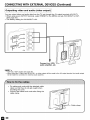
CONNECTING WITH EXTERNAL DEVICES (Continued)
IConnecting
a VCR, DVD player or a video camera
(AV-INI/2/COMPONENT)
1
iii_!!_
¸¸;ii_i_iii_>i!ii_i_iiii_i!i!!!!iiiii!_i!iii:!:!!!!ii!!!i!i!i!ii
1
__
_Video
_
Audio
_'\
Audio
(L)
(R)
VCR
PB
PR
--V
_
_
Audio
(L)
Audio
(R)
DVD
Video
Player
camera
VCR
• If your VCR (or other external devices) has an S-Video terminal, S-VIDEO connection is recommended. (Use an
S-Video cable.)
• When you connect external devices to both S-VIDEO and VIDEO terminals (and if you select AV-IN1), you can
only view pictures from the S-VIDEO terminal.
• You cannot view multiple or synthesized pictures by connecting two or more external devices. When connecting
an external device, use care to connect the video and audio cables to the corresponding terminals.
• Do not connect antennas or headphones to AV-IN1.
CONNECTING WITH EXTERNAL DEVICES (Continued)
I Outputting
video and audio
(video output)
I
You can output video and audio data from the TV set through the AV output terminals (AV-OUT).
• When using as an OUTPUT terminal, select PRESET in the MENU and set AV2 IN/OUT to OUT.
(See page 26.)
• The factory setting for AV2 IN/OUT is IN.
;
f'
Connect to a VCR,
audio amplifier, etc.
• AV2 has 2 OUT modes (see page 26).
• When using the S-Video input for AV-IN1, no video output will be made to the AV output terminal, but audio output
will be made for connection to external audio systems.
• Fix cables and cords with the attached cable
clamp so that they do not get caught when
mounting the cover.
• Connect the cables and cords after fixing the
cable clamp.
Cable clamp
J
m
_
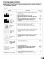
TROUBLESHOOTING
• Before calling for repair service, check the following
the encountered symptoms.
items for possible remedies to
I TV set
Problem
There is no
picture or
sound.
There is no
picture.
There is no
picture from
AV-INI.
Thereis
sound.
_:::::::::::::::::::
no
There is no
picture or
sound, just
noise.
Picture
isnot
I
;.
J
•
Reference
Pages
Check item
• Make sure the AC adapter
power outlet.
• Reception other than those
can be considered.
• Make sure the input mode
• Make sure the main power
on.
is properly inserted in the
of broadcasting
9
stations
is set to TV.
switch of the main unit is
• Make sure the BLACK LEVEL is properly adjusted.
• Fluorescent lamp may have reached the end of
service life.
• Make sure the S-Video terminal is free of connections.
16
16
24,25
43
39
• Make sure the volume is not set to minimum.
• Make sure the sound is not set to mute.
• Make sure that headphones are not connected.
17
17
13
• Make sure the antenna cable is properly connected.
• Consider whether TV signals are being properly
received.
9
• Make sure the antenna cable is properly connected.
• Consider whether TV signals are being properly
received.
9
clear.
Picture is light
• Check color adjustment.
• Check color system setting.
24,25
24,25
Jorimproperly
.... tinted.
The picture is
too dark.
Remote control does not work.
• Press the BRIGHT button.
• Check PICTURE and BLACK LEVEL adjustment.
• Fluorescent lamp may have reached the end of
service life.
• Check the batteries of the remote control.
• Make sure the remote sensor window is not under
strong lighting.
15
24,25
43
8
8
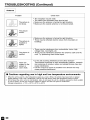
TROUBLESHOOTING
(Continued)
I Antenna
Problem
Check item
The picture is
not sharp.
•
•
•
•
The reception may be weak.
The state of the broadcast may also be bad.
Make sure the antenna is facing the right direction.
Make sure the outside antenna is not disconnected.
The picture
moves.
The picture is
doubled or
tripled.
The picture is
spotted.
There
stripes
screen
colors
• Cautions
are
on the
or
fade.
regarding
• Make sure the antenna is facing the right direction.
• There may be reflected electric waves from mountains
buildings.
• There may be interference
voltage lines, neon lights,
• There may be interference
cord. Try positioning them
or
from automobiles, trains, high
etc.
between the antenna cable and AC
further apart.
• Is the unit receiving interference from other devices?
Transmission antennas of radio broadcasting stations, transmission antennas of amateur radios and cellular phones may also
cause interference.
• Use the unit as far apart as possible from devices that may
cause possible interference.
use in high
and low temperature
environments
• When the unit is used in a low temperature space (e.g. room, office), the picture may leave trails or appear
slightly delayed. This is not a malfunction, and the unit will recover when the temperature returns normal.
• Do notleave the unit in a hot or cold location. Also, do not leave the unit in a location exposed to direct sunlight
or near a heater, as this may cause the cabinet to deform and the LCD panel to malfunction.
Storage temperature: -4°F to +140°F (-20°C to +60°C)
m
SPECIFICATIONS
Items
LC-20E
Model
1U
LCD panel
19.7" ASV & BLACK-TFT
Number of dots
921,600 dots VGA
Video color systems
Destination
N358, N443, PAL, PAL-M, PAL-N, SECAM,
TV Standard
TV function
USA!Latin
(CCIR)
3 Dimensional
NTSC/PAL-M/PAL-N
PLL 181 ch.
STEREO
MTS+SAP
Y/C separation
125 ch.
circuit
Yes (N358 only)
Digital comb filter
Yes
Brightness
430 cd/m 2
Lamp life
60,000 hours
Viewing angles
H: 170 ° V: 170 °
Audio amplifier
2.5 W × 2
Speakers
Terminals
PAL-60
A!Twn
TV Tuning System
CATV
LCD
1 37/_ x 2 3/4in. (4 x 7 cm), 2 pcs.
AVl
AV-IN1, S-VIDEO-IN
AV2
AV-IN2/AV-OUT
COMPONENT
COMPONENT-IN,
Antenna
F-Type
Headphone
Mini-jack
AUDIO-IN
for stereo (0 3.5 ram)
OSD language
English/French/Spanish
Power supply
DC 13 V, AC 110-240
Weight
15.7 Ibs (7.1 kg), w/o accessories
V, 50/60 Hz
Accessories
Remote control, Batteries, Antenna cable, AC adapter,
AC cord, Cable clamp, Operation Manual
As a part of policy of continuous improvement, SHARP reserves the right to make design and specification changes for
product improvement without prior notice. The performance specification figures indicated are nominal values of
production units. There may be some deviations from these values in individual units.
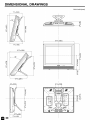
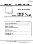
DIMENSIONAL
DRAWINGS
Unit: inchl(mm)
7_/_ (189)
19_3/32(493)
I
I
79/32(185)
1229132
(328)
I
I
I
I
I
I
v
z
101_4(261)
43/64
315/16
7%2 (182)
CALLING
FOR SERVICE
For location of the nearest Sharp Authorized
assistance, please call 1-800-BE-SHARE
Service,
or to obtain product
literature,
accessories,
supplies,
or customer
LIMITED WARRANTY
END-USER
LIMITED WARRANTY
SHARP ELECTRONICS CORPORATION warrants to the first end user purchaser that this Sharp brand product (the
"Product"), when shipped in its original container, will be free from defective workmanship and materials, and agrees that it
will, at its option, either repair the defect or replace the defective Product or part thereof with a new or remanufactured
equivalent at no charge to the purchaser for parts or labor for the period(s) set forth below.
This warranty does not apply to any appearance items of the Product nor to the additional excluded item(s) set forth below
nor to any Product the exterior of which has been damaged or defaced, which has been subjected to improper voltage or
other misuse, abnormal service or handling, or which has been altered or modified in design or construction.
In order to enforce the rights under this limited warranty, the purchaser should follow the steps set forth below and provide
proof of purchase to the servicer.
To the extent permitted by applicable state law, the warranties set forth herein are in lieu of, and exclusive of, all other
warranties, express or implied. Specifically, ALL OTHER WARRANTIES OTHER THAN THOSE SET FORTH ABOVE ARE
EXCLUDED. ALL EXPRESS AND IMPLIED WARRANTIES INCLUDING THE WARRANTIES OF MERCHANTABILITY,
FITNESS FOR USE, AND FITNESS FOR A PARTICULAR PURPOSE ARE SPECIFICALLY EXCLUDED. If, under
applicable state law, implied warranties may not validly be disclaimed or excluded, the duration of such implied warranties is
limited to the period(s) from the date of purchase set forth below.
Neither the sales personnel of the seller nor any other person is authorized to make any warranties other than those
described herein, or to extend the duration of any warranties beyond the time period described herein on behalf of Sharp.
The warranties described herein shall be the sole and exclusive warranties granted by Sharp and shall be the sole and
exclusive remedy available to the purchaser. Correction of defects, in the manner and for the period of time described
herein, shall constitute complete fulfillment of all liabilities and responsibilities of Sharp to the purchaser with respect to the
Product, and shall constitute full satisfaction of all claims, whether based on contract, negligence, strict liability or otherwise.
In no event shall Sharp be liable, or in any way responsible, for any damages or defects in the Product which were caused
by repairs or attempted repairs performed by anyone other than an authorized servicer. Nor shall Sharp be liable or in any
way responsible for any incidental or consequential economic or property damage. Some states do not allow limits on
warranties or on remedies for breach in certain transactions; in such states, the limits herein may not apply.
Model Specific Section
Your Product Model Number & Description:
LC-20E1U
LCD Color Television
(Be sure to have this information
your Product.)
available when you need service for
Warranty Period for this Product:
One (1) year parts and labor from the date of purchase.
Additional Item(s) Excluded from
Warranty Coverage (if any):
None
Where to Obtain Service:
From a Sharp Authorized Servicer located in the United States.
To find the location of the nearest Sharp Authorized Servicer, call
Sharp toll free at 1-800-BE-SHARP.
What to do to Obtain
Ship prepaid or carry in your Product to a Sharp Authorized Servicer.
Be sure to have Proof of Purchase available. If you ship the Product,
be sure it is insured and packaged securely.
Service:
TO OBTAIN PRODUCT
INFORMATION,
CALL 1-888-LCD-SHARP
OR VISIT www.sharpusa.com
SHARR
SHARP
ELECTRONICS
Sharp Plaza, Mahwah,
SHARP
CORPORATION
New Jersey 07430-2135
CORPORATION
SHARP
"
.,.,TED
WA..A.T
Consumer
Electronics
Congratulations
Sharp Electronics
of Canada Ltd. (hereinafter
Sharp brand product,
Products
|
on your purchase!
called "Sharp") gives the following
when shipped in its original container
"|
express
and sold or distributed
|
warranty to the first consumer
purchaser
in Canada by Sharp or by an Authorized
for this
Sharp Dealer:
Sharp warrants that this product is free, under normal use and maintenance, from any defects in matedal and workmanship.
If any such
defects should be found in this product within the applicable warranty period, Sharp shall, at its option, repair or replace the product as
This
warranty
shall not apply to:
specified
herein.
(a) Any defects caused or repairs required
use as outlined in the owner's manual
as a result of abusive
accident,
improper
installation
or inappropriate
by any party other than Sharp, Sharp's Authorized
I
(c)
Damage caused or repairs required as a result of the use with items not specified
head cleaning tapes and chemical cleaning agents.
(d)
•
•
(g)
(h)
Any replacement of accessories, glassware, consumable or peripheral items required through normal use of the product including but
not limited to earphones, remote controls, AC adapters, batteries, temperature probe, stylus, trays, filters, belts, ribbons, cables and
paper.
Any cosmetic damage to the surface or exterior that has been defaced or caused by normal wear and tear.
Any damage caused by external or environmental
conditions, including but not limited to transmission
line/power line voltage or liquid
spillage.
Any product received without appropriate model, serial number and CSA/cUL markings.
Any products used for rental or commercial purposes.
(i)
Any installation,
•
EE
•
•
or approved
by Sharp,
including
Service Centres
I
Any Sharp product tampered with, modified,
or Sharp's Authorized Servicing Dealers.
setup and/or programming
or repaired
negligence,
•
(b)
(e)
(f)
adiusted
operation,
•
•
but not limited to •
charges.
Should this Sharp product fail to operate during the warranty period, warranty service may be obtained upon delivery of the Sharp product
together with proof of purchase and a copy of this LIMITED WARRANTY
statement to an Authorized
Sharp Sendce Centre or an
Authorized Sharp Servicing Dealer. In home warranty service may be provided at Sharp's discretion on any Sharp television with the
screen size of 27" or larger and on any Sharp Over-the-Range
Microwave Oven.
m
•
m
•
•
I
I
This warranty constitutes the entire express warranty granted by Sharp and no other dealer, service centre or their agent or employee is
authorized to extend, enlarge or transfer this warranty on behalf of Sharp. TO the extent the law permits, Sharp disclaims any and all
liability for direct or indirect damages or losses or for any incidental, special or consequential damages or loss of profits resulting from a •
defect in material or workmanship relating to the product, including damages for the loss of time or use of this Sharp product or the loss •
of information. The purchaser will be responsible for any removal, reinstallation, transportation
and insurance costs incurred. Correction of
defects, in the manner and period of time described herein, constitute complete fulfillment of all obligations and responsibilities
of Sharp
to the purchaser with respect to the product and shall constitute full satisfaction of all claims, whether based on contract, negligence, strict
liability or otherwise.
WARRANTY
PERIODS:
Audio Products
Camcorder
DVD Products
LCD Projector
LCD TV
Microwave Oven
Television Products
VCR Product
Vacuum Cleaner
Parts &
1 year
I year
I year
I year
1 year
2 years
I year
1 year
1 year
Labour (exceptions noted)
•
•
I
Clamp 90 days)
(magnetron component-3
(picture tube component-t
additional years)
additional year)
TO obtain the name and address ot' the nearest Authorized Sharp Service Centre or Dealer, please contact:
SHARP ELECTRONICS
OF CANADA LTD. 335 Britannia Road East Mississauga, Ontario L4Z IW9
For more information on this Warranty, Sharp Extended Warranty
Offers, Sharp Canada Products, Accessory Sales, Dealer or Service
Locations, please call (905) 568-7140
Visit our Web site: www.sharp.ca
•
•
•
I
SHAJ_IP'
=2
_
•
•
•
_"
m
_
SERVICE