1
NM 1
NETWORK MIC PREAMP
IMPORTANT SAFETY INSTRUCTIONS
1. Read these instructions.
2. Keep these instructions.
3. Heed all warnings.
4. Follow all instructions.
5. Do not use this apparatus near water.
6. Clean only with a dry cloth.
7. Do not block any ventilation openings. Install in accordance with manufacturer’s instructions.
8. Do not install near any heat sources such as radiators, registers, stoves, or other apparatus (including amplifiers) that produce heat.
9. Do not defeat the safety purpose of the polarized or grounding-type plug. A polarized plug has two blades with one wider than the
other. A grounding-type plug has two blades and a third grounding prong. The wide blade or third prong is provided for your safety.
If the provided plug does not fit into your outlet, consult an electrician for replacement of the obsolete outlet.
10. Protect the power cord and plug from being walked on or pinched particularly at plugs, convenience receptacles, and the point
where it exits from the apparatus.
11. Only use attachments and accessories specified by Rane.
12. Use only with the cart, stand, tripod, bracket, or table specified by the manufacturer, or sold with the apparatus. When a cart is
used, use caution when moving the cart/apparatus combination to avoid injury from tip-over.
13. Unplug this apparatus during lightning storms or when unused for long periods of time.
14. Refer all servicing to qualified service personnel. Servicing is required when the apparatus has been damaged in any way, such
as power supply cord or plug is damaged, liquid has been spilled or objects have fallen into the apparatus, the apparatus has been
exposed to rain or moisture, does not operate normally, or has been dropped.
15. The plug on the power cord is the AC mains disconnect device and must remain readily operable. To completely disconnect this
apparatus from the AC mains, disconnect the power supply cord plug from the AC receptacle.
16. This apparatus shall be connected to a mains socket outlet with a protective earthing connection.
17. When permanently connected, an all-pole mains switch with a contact separation of at least 3 mm in each pole shall be
incorporated in the electrical installation of the building.
18. If rackmounting, provide adequate ventilation. Equipment may be located above or below this apparatus, but some equipment
(like large power amplifiers) may cause an unacceptable amount of hum or may generate too much heat and degrade the
performance of this apparatus.
19. This apparatus may be installed in an industry standard equipment rack. Use screws through all mounting holes to provide the best
support.
WARNING: To reduce the risk of fire or electric shock, do not expose this apparatus to rain or moisture. Apparatus shall not be exposed to dripping or splashing and no objects filled with liquids, such as vases, shall be placed on the apparatus.
WARNING: This product may contain chemicals known to the State of California to cause cancer, or birth defects or other
reproductive harm.
FCC Statement
NOTE: This equipment has been tested and found to comply with the limits for a Class B digital device, pursuant to part 15 of the
FCC Rules. These limits are designed to provide reasonable protection against harmful interference in a residential installation. This
equipment generates, uses and can radiate radio frequency energy and, if not installed and used in accordance with the instructions,
may cause harmful interference to radio communications. However, there is no guarantee that interference will not occur in a particular installation. If this equipment does cause harmful interference to radio or television reception, which can be determined by turning
the equipment off and on, the user is encouraged to try to correct the interference by one or more of the following measures:
• Reorient or relocate the receiving antenna.
• Increase the separation between the equipment and receiver.
• Connect the equipment into an outlet on a circuit different from that to which the receiver is connected.
• Consult the dealer or an experienced radio/TV technician for help.
CAUTION: Changes or modifications not expressly approved by Rane Corporation could void the user's authority to operate the
equipment.
This Class B digital apparatus complies with Canadian ICES-003.
Cet appareil numérique de la classe B est conforme à la norme NMB-003 du Canada.
Shielded CAT5e or better cables are required in order to comply with the FCC Rules part 15 limits for a Class B digital device.
INSTALLATION MANUAL
NM 1
NETWORK MIC PREAMP
In Use / Conductor
Link / Activity
COBRANET
PRIMARY
COBRANET
SECONDARY
SPEAKER
In Use / Conductor
Link / Activity
MIC INPUT
SWITCHES / LIGHTS
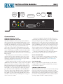
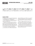
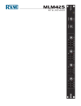
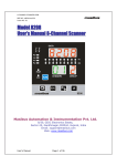
Connections
COBRANET PRIMARY Connector
COBRANET SECONDARY Connector
These Neutrik Ethercon connectors accept CAT 5e Ethernet
cables terminated with the standard RJ-45 plug. They are used
as the Primary and Secondary connections to a LAN carrying
CobraNet data. The Ethercon connectors also accept a Neutrikdesigned housing for RJ-45 plugs (Neutrik NE8MC series)
that is similar to the industry standard XLR connector. This
Ethercon plug is much more rugged than the standard RJ-45; a
version of the housing is available to retrofit over CAT 5e cables
that are already terminated. (Note that certain cables such as
Belden MediaTwist require special strain-reliefs to work with the
Ethercon shell.)
The cabling used to connect the NM 1 to other Ethernet
equipment must be CAT 5e minimum. CAT 6 is also acceptable. For more information about CobraNet network design,
redundancy, and Primary and Secondary ports, please refer to
the CobraNet website www.cobranet.info.
Both the Primary and the Secondary ports fully support PoE
(IEEE 802.3af). For the NM 1 to operate, at least one of the two
Ethernet ports must be connected to a device that is an IEEE
802.3af compliant Power Source Equipment (PSE). Power can
be supplied to the NM 1 through either the unused pairs of the
CAT 5 cable, or in a “phantom power” scheme using the data
pairs. This allows the use of PSE devices from manufacturers
that support either scheme. The NM 1 requests the maximum
power, approximately 13W, on both ports (see data sheet for
more details on power requirements). The PSE must be chosen
carefully to ensure that it can provide full power to every port
that is connected to a NM 1.
Power can be supplied to the NM 1 through either port; it
automatically switches between the ports to support fully redundant system designs. If power is available on both ports, the
NM 1 chooses one as the active power port. PoE supports equipment hot-plugging, so a PSE senses when a load is disconnected
and stops delivering power on that port. To allow the fastest possible switch-over from the active port, the stand-by port always
draws a minimum current from its PSE so the PSE is awake and
ready to deliver power as soon as the NM 1 needs it. This allows
seamless redundancy in the power supply to the NM 1.
Note the port the NM 1 chooses to power from is independent from the port that is being used for CobraNet data.
In Use / Conductor LEDs
There is one yellow LED for each CobraNet port. This indicator lights on the port in use and blinks if the device is also the
Conductor. (More documentation is at www.cobranet.info)
Link / Activity LEDs
There is one green LED for each CobraNet port. This indicator lights when Link is established and blinks when CobraNet
network activity is detected.
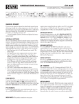
SWITCHES / LIGHTS Connector
This female DB-15 connector allows an external switch and lamp
panel to be attached for push-to-talk, cough mute, and other
similar functions. It is provided with lugs so that any DB-15 plug
with mounting ears and spring-latches can be used (e.g. Amp
part numbers for the spring latch are 745779-3 (bulk), 745779-2
(two/bag), 745255-3 (bulk) or 745255-2 (two/bag) )
CASE
OPTIONAL
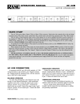
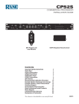
Switches / Lights Connector
Pinout
Pin 7
Ground
Pin 8
Ground
Pin 9
Ground
Pin 10
Ground
Pin 11
Talk LED
Pin 12
Cough LED
Pin 13
NC
Pin 14
Override LED
Pin 15
Private LED
MIC INPUT Connector
The balanced microphone input is an industry standard XLR-3
type connector (see the NM 1 Data Sheet for specifications).
Gain is adjusted via SNMP control. IEC 61938 P48 compliant
48V phantom power is provided.
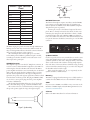
Connect pins 2 and 3 to the balanced output of the microphone. Pin 1 is directly connected to the chassis; for best noise
immunity, the microphone cable should have a braid or double
wound shield. If a cable such as Belden 1800F is used that has
both a wire shield and a drain wire, then all the shield wires and
not just the drain wire should be connected to pin 1 of the XLR
connector.
SysName
1
2
3
45
23
4
45
23
89
67
45
23
89
67
45
23
89
67
SPEAKER Connector
This amplifier output is a standard ¼" TRS phone connector. It
is used to connect a 4Ω minimum loudspeaker to the NM 1 for
monitoring the selected CobraNet audio channel. The NM 1
power amplifier can deliver 1 watt continuously into an 8Ω load
with a pink noise signal that has a 15 dB crest factor (see data
sheet for detailed specifications). The output configuration requires that the positive and negative signals must remain isolated
from the chassis and from ground. The plug used must be TRS;
use of a TS (i.e. mono) phone plug shorts the power amplifier
and causes a malfunction.
The threaded metal bushing allows use of a ¼" phone plug
with a threaded locking ring (e.g., Switchcraft Number 298).
The connector sleeve is connected directly to chassis ground;
the tip is the positive signal; the ring is the negative signal.
NM 1
Rane Corp.
Made in U.S.A.
89
67
The LED output pins provide +12 VDC through 160Ω current
limiting resistors when they are turned on. When turned off,
they are floating. LED indicators should be connected between
these pins and ground pins on this connector.
The switch inputs have internal pull-ups to +3.3 VDC
and are ESD protected. When a pushbutton input is needed,
normally-open switches should be connected between one of
these inputs and a ground pin.
01
Ground
EF
Pin 6
01
Private button
EF
Pin 5
Figure 2. Mic wiring
01
Override button
EF
Pin 4
01
NC
EF
Pin 3
CD
AB
Cough button
CD
AB
Pin 2
(–)
3
1
CD
AB
Talk button
2
CD
AB
Pin 1
(+)
COMMERCIAL AUDIO
EQUIPMENT 24TJ
R
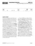
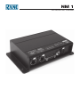
SysName Switches
On the rear panel are four rotary switches that are used to create
a four digit identifier that becomes part of the SNMP variable,
sysName. sysName is then used to uniquely identify a CobraNet
device on the network. The condition of being unique requires
that each device on the network have a different setting. Looking
at the unit with the switches facing you, as in the above diagram,
the identifier reads from left to right.
Thus, setting the switches to 1, A, 3, 7, respectively, sets the
sysname variable to “NM1-Sw1A37.”
Mounting
The NM 1 is equipped with mounting ears to solidly attach it to
a surface if needed. Rubber feet are also included for tabletops.
SNMP
If you are new to SNMP or would like an easy overview, see the
RaneNote "SNMP: Simple? Network Management Protocol at
www.rane.com/note161.html.
Software
Refer to the NM 1 Data Sheet for software information.
–
+
Figure 1. Speaker wiring
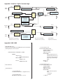
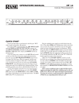
Appendix 1. Switches / Lights Connector Logic
Pin 2
Cough
Button
Internal pull-up,
debounce and
ESD protection.
Pin 12
SNMP: cough (read-only)
SNMP: coughDisable (read-write)
*
*
SNMP: talkToggle (read-write)
SNMP: talk
(read)
Flip-Flop
Toggle
Pin 1
Talk
Button
Internal pull-up,
debounce and
ESD protection.
Q
Toggle
SNMP: microphoneMute
(read-only)
1
2
3
Pin 11
SNMP: talk (write)
0 = clear flip-flop
1 = set flip-flop
“edge-triggered”
*
Pin 4
Override
Button
Internal pull-up,
debounce and
ESD protection.
*
SNMP: overrideDisable
(read-write)
1
2
3
Pin 14
SNMP: override (read-only)
*
*
Flip-Flop
SNMP: privateModeToggle (read-write)
Pin 5
Privacy
Button
Internal pull-up,
debounce and
ESD protection.
*
*Ground pins on the DB-15
connector are 6, 7, 8, 9, &10.
Toggle
Toggle
Pin 15
Q
SNMP: privateMode (read)
SNMP: privateMode (write)
0 = clear flip-flop
1 = set flip-flop
“edge-triggered”
*
Pins 3 & 13 on the DB-15
connector are no-connects.
See the MIB for
explanation of variables.
Appendix 2. NM 1 MIB
--- RANE-NM1-MIB-V1.my
-- MIB generated by MG-SOFT Visual MIB Builder Version 4.0 Build 341
-- Thursday, May 20, 2004 at 17:53:02
-
RANE-NM1-MIB-V1 DEFINITIONS ::= BEGIN
IMPORTS
mfgExtensions
FROM PEAKAUDIO-MIB
OBJECT-TYPE
FROM RFC-1212
Counter
FROM RFC1155-SMI;
--- Node definitions
--- Node definitions
--- 1.3.6.1.4.1.2680.1.2.7
rane OBJECT IDENTIFIER ::= { mfgExtensions 7 }
-- 1.3.6.1.4.1.2680.1.2.7.3
NM1 OBJECT IDENTIFIER ::= { rane 3 }
-- 1.3.6.1.4.1.2680.1.2.7.3.1
micPreampGain OBJECT-TYPE
SYNTAX INTEGER (10..65)
ACCESS read-write
STATUS mandatory
DESCRIPTION
"Gain through the mic pre-
amplifier stage. Gain can be adjusted in 1 db increments in the range 10dB through
65dB."
DEFVAL { 10 }
::= { NM1 1 }
-- 1.3.6.1.4.1.2680.1.2.7.3.2
microphoneMute OBJECT-TYPE
SYNTAX INTEGER
ACCESS read-only
STATUS mandatory
DESCRIPTION
"State of the microphone mute.
0 - unmuted
1 - muted"
::= { NM1 2 }
-- 1.3.6.1.4.1.2680.1.2.7.3.3
talk OBJECT-TYPE
SYNTAX INTEGER
ACCESS read-write
STATUS mandatory
DESCRIPTION
"Present state of the talk button flip flop.
0 - off
1 - on"
::= { NM1 3 }
-- 1.3.6.1.4.1.2680.1.2.7.3.7
override OBJECT-TYPE
SYNTAX INTEGER
ACCESS read-only
STATUS mandatory
DESCRIPTION
"Present state of the override
momemtary button.
0 - not depressed
1 - depressed"
::= { NM1 7 }
-- 1.3.6.1.4.1.2680.1.2.7.3.4
talkToggle OBJECT-TYPE
SYNTAX Counter
ACCESS read-write
STATUS mandatory
DESCRIPTION
"Toggle the talk button flip flop. Set this variable to any value other than its current value to cause the flip flop to
change state."
::= { NM1 4 }
-- 1.3.6.1.4.1.2680.1.2.7.3.8
overrideDisable OBJECT-TYPE
SYNTAX INTEGER
ACCESS read-write
STATUS mandatory
DESCRIPTION
"Control for disabling override button from the audio muting logic. Override indicator will continue to function normally but audio will not be affected.
0 - override function enabled
- default
1 - override function disabled"
::= { NM1 8 }
-- 1.3.6.1.4.1.2680.1.2.7.3.5
cough OBJECT-TYPE
SYNTAX INTEGER
ACCESS read-only
STATUS mandatory
DESCRIPTION
"Present state of the cough momentary button.
0 - not depressed
1 - depressed"
::= { NM1 5 }
-- 1.3.6.1.4.1.2680.1.2.7.3.9
privateMode OBJECT-TYPE
SYNTAX INTEGER
ACCESS read-write
STATUS mandatory
DESCRIPTION
"Present state of the private mode button flip flop.
0 - off
1 - on"
::= { NM1 9 }
-- 1.3.6.1.4.1.2680.1.2.7.3.6
coughDisable OBJECT-TYPE
SYNTAX INTEGER
ACCESS read-write
STATUS mandatory
-- 1.3.6.1.4.1.2680.1.2.7.3.10
DESCRIPTION
privateModeToggle OBJECT-TYPE
"Control for disabling cough SYNTAX Counter
button from the audio ACCESS read-write
muting logic. Cough STATUS mandatory
indicator will continue to DESCRIPTION
function normally but audio "Toggle the private mode
will not be affected.
button flip flop. Set this
0 - cough function enabled variable to any value other
- default
than its current value to
1 - cough function disabled"
cause the flip flop to change
::= { NM1 6 }
state."
::= { NM1 10 }
END
--- RANE-NM1-MIB-V1.my
--
©Rane Corporation 10802 47th Ave. W., Mukilteo WA 98275-5000 TEL 425-355-6000 FAX 425-347-7757 WEB rane.com
All features & specifications subject to change without notice 108422