1
OWNER'S
MANUAL
10
Veutilation
Slots and openiugs in the cabinet are provided
for veutilation and to ensure reliable operation of tile
product and to protect it lhom overheating, and these
opeuiugs must not be blocked or covered. The opeuiugs
should never be blocked by placing tile product on a bed.
sofa. rug, or other similar surface. This product should not
be placed in a built-in iustallation such as a bookcase or rack
unless proper ventilation is provided or the manufacturer's
instructions have been adhered to.
11
Power Sources
This product should be operated only from
tile type of power source indicated on the marking labeh If
you are uot sure of tile type of power supply to your home.
consult your product dealer or local power company. For
products intended to operate lhom battery power, or other
sources, refer to tile operating instructions.
GroutKliug or Polarization
This product may be equipped
with a polarized altertmtiug current line plug (a plug having
one blade wider than tile other). This plug will fit into the
power outlet only one way. This is a safety feature. If you
are uuable to insert tile plug fully into the outlet, try
reversiug tile plug. If the plug should still fail to fit. contact
your electrician to replace your obsolete outlet. Do not
defeat the safety purpose of the polarized plug.
Power-Cord Protection
Power-supply cords should be
routed so that they are uot likely to be walked on or pinched
by items placed upon or agaiust them, payiug particular
attention to cords at plugs, convenieuce receptacles, and tile
point where they exit from tile product.
CAUTION
RISK OF ELECTRICSHOCK
DONOTOPEN
CAUTION:
Z
TO REDUCE THE RISK OF
ELECTRIC SHOCK, DO NOT REMOVE
COVER (OR BACK). NO USER-SERVICEABLE
PARTS INSIDE. REFER SERVICING TO
QUALIFIED SERVICE PERSONNEL.
•
Explanation
The lighming
flash
of Graphical
with
arrowhead
Symbols
symbol,
within
an
equilaleral triangle, is inlended to alert you lo lhe
prc_nce of uninsulated 'dangerous voltage" within
the produces enclosure that may be of sullicient
magnitude to constitute a risk of electric shockto
12
persons.
The exclamatkm point within an equilatcral triangle
is intended to Melt you to the prc_nce of important
operating and maintmmnce/servicing) instructkms in
the literaturc accompanying the appliance.
1
Read lustructiotts
All tile safety aud operatiug instructions
should be read before the product is operated.
2
Retain Itlstructious
The safety aud operatiug instructions
should be retained for future reference.
:3
Heed Warnings
All wartfiugs on the product and in the
operatiug instructions should be adhered to.
4
Follow Instructions
should be followed.
5
Cleatfing
Unplug this product lhom the wall outlet before
cleaniug. Do uot use liquid cleaners or aerosol cleaners. Use
a damp cloth for cleaning.
Attachments
Do not use attachments not recommended by
the product manufacturer as they may cause hazards.
Water and Moisture
Do not use this product near water
for example, near a bath tub. wash bowl. kitchen sink. or
laundry tub: in a wet basement: or near a swinuning pool:
and tile like.
6
7
8
9
13
14
All operatiug and use instructions
Accessories
Do not place this product on an uustable cart.
stand, tripod, bracket, or table. Tile product may fall.
causing serious injury to a child or adult, and serious
damage to the product. Use only with a cart. stand, tripod.
bracket, or table recommended by tile matmfacturer, or sold
with tile product. Any mountiug of the product should
follow tile manufacturer's instructions, and should use a
tuouutiug accessory recommended by the manufacturer.
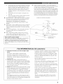
A product and cart combiuation should be moved with care.
Quick stops, excessive force, aud uneven
surfaces may cause tile product and cart
coulbiuatiou
to overturu.
Liglltuiug
For added protection lk_rthis product during a
lightning storm, or when it is left uuattended and unused for
long periods of time. unplug it lhom the wall outlet and
disconnect the antenna or cable system. This will prevent
damage to tile product due to lightning and power-line
surges.
]5
Power Lines An outside auteuua system should uot be
localed in the vicinity of overhead power lines or other
electric light or power circuits, or where it can fall into such
power lines or circuits. When installing an outside antenna
system, extreme care should be token to keep from touching
such power lines or circuits as contact with them might be
fatal.
16
Overloading
Do not overload wall outlets, extension
cords, or integral convenience receptacles as this can result
in a risk of fire or electric shock.
17
Object and Liquid Eulry Never push objects of any kind
into this product through openings its they may touch
dangerous w_ltage points or short-out parts that could result
iu a fire or electric shock. Never spill liquid of any kind on
the product.
Servicing
Do not attempt to service this product yourself
its opeuiug
or reliioviug
covers
may expose yOU to
dangerous voltage or other hazards. Refer N1 servicing to
qualified service persouneh
18
19
Damage Requiriug Service
Unphlg this product from the
wall outlet and refer serviciug to qualified service personnel
under tile following conditions:
a)
b)
When the power-supply cord or plug is damaged,
If liquid has been spilled, or objects have fallen into the
product.
c)
If the product has been exposed to rain or water.
rj¢l.[e]:if_q_Tiiii,_f:l_llJ,d_hT_,_l:llie;Jl[e]LT
d/ IfIheproduct
does
noloperate
normally
by,
folluwing 24
tile operating instructions. Atliusl only those controls
that are covered by the operating instructions as an
improper atljuslmeot uf other coulrols may result in
damage and will ofleu require extensive work by, a
qualified technician Io reslore the product to ils normal
operalion.
e)
If Ihe product has beer( dropped or damaged in any
way, (-u(d
f/
When the product exhibits a distinct change in performance - this indicates a lined for service.
20
Replacement Parts When replacement parts are required.
be sure the service teclmiciau has used replacement parts
specified by the malmfacturer or have the same
characteristics as Ihe original part. Ummlhorized
subslitutions may result in fire. electric shock, or other
hazards.
21
Safely Check Upon completion of any service or repairs Io
Ihis producL ask tile service lechnician Io perform safety
checks to determine that the product is in proper operating
condition.
_
22
;- -
Outdoor Antenna Grounding
If an outside antenna or
cable system is commcted to the product, be sure the antemm
or cable system is grounded so as to provide some
protection against voltage surges and built-up static charges.
Article 810 of the National Electrical Code. ANSI/NFPA 70.
provides information with regard to proper grounding of the
mast and supporting structure, grounding of the lead-in wire
to an autemla discharge unit. size of grounding conductors.
location of antenna discharge (((lit. connection to grounding
electrodes, and requirements for the grounding electrode.
EXAMPLE
OF ANTENNA
GROUNDING
/
/
Wall or Ceiling Mouuth(g
The unit should be mounted
Io a wall or ceiling only as recommended by the
m(-mufact
23
urer.
Heal The product should be situated away from heat
sources such as r,_tdi,_tlors, he(-ttregisters, sloves, or ()tiler
products (inchlding amplifiers) Ihal produce heat.
Note to CATV system installer:
This reminder is provided to call the CATV system installer's
attention to Article 820-40 of the NEC that provides
guidelines for proper grounding and, in particular, specifies
that the cable ground shall be commcted to the grounding
system of the buikling, as close to the point of cable entry as
practicah
NEC
FCC INFORMATION
1
IMPORTANT
UNIT!
NOTICE: DO NOT MODIFY
THIS
Modifications
(lot expressly approved by
Yamaha may void your authority, granted by tile FCC. to
use the product.
2
IMPORTANT:
When comlectiug this product to
accessories aud/or another product use only high quality
shielded cables. Cable/s supplied with this product MUST
be used. Follow all installation instructions. Failure to
follow instructions could void your FCC authorization
3
to
use this product in the USA.
NOTE: This product has been tested and found to comply
with the requirements listed in FCC Regulations. Part 15
for Class "B" digital devices. Compliance with these
requirements provides a reasonable level of assurance that
your use of this product in a residential environment will
not result in harmful interference with other electronic
devices.
This equipment generatesklses
ELECTRICAL
CODE
(for US customers)
Compliance with FCC regulations does not guarantee that
interference will not occur in all installations. If this
This product, when installed as indicated in tile
instructions contained in this manual, meets FCC
requirements.
NATIONAL
radio frequencies and. if
not installed and used according to the instructions found
in the users manual, may cause interference harmful to the
operation of other electronic devices.
product is found to be tile source of interference, which
ca(( be determined by turning tile unit "OFF" and "ON",
please try to eliminate tile problem by using one of the
following measures:
Relocate either this product or the device that is being
affected by the interference.
Utilize power outlets that are on different branch (circuit
breaker or fuse) circuits or install AC line filter/s.
In the case of radio or TV interference, relocate/reorient
the antenna. If the antenna leadqn is 300 ohm ribbon lead
change the lead-in to coaxial type cable.
If these corrective measures do not produce satisfactory
results, please contact the local retailer authorized to
distribute this type of product. If you carl not locate the
appropriate retailer, please contact Yamaha Electronics
Corp.. U.S.A. 6660 Orangethorpe Ave. Buena Park. CA
90620.
The above statements apply ONLY to those products
distributed by Yamaha Corporation of America or its
subsidiaries.
1
To assure the finest performance, please read this
manual carefully. Keep it in a safe place for future
reference.
14 Do not attempt to modify or fix this unit. Contact
qualified YAMAHA service personnel when any
service is needed. The cabinet should never be
2
Install this sound system in a well ventilated, cool,
dry, clean place - away from direct sunlight, heat
sources, vibration, dust, moisture, and/or cold.
Allow ventilation space of at least 30 cm on the top,
15 When not planning to use this unit for long periods
of time (i.e. vacation), disconnect the AC power plug
from the wall outlet.
20 cm on the left and right, and 20 cm on the back of
this unit.
3
4
Locate this unit away from other electrical
appliances, motors, or transformers to avoid
humming sounds.
Do not expose this unit to sudden temperature
changes from cold to hot, and do not locate this unit
in a environment with high humidity (i.e. a room with
a humidifier) to prevent condensation inside this
unit, which may cause an electrical shock, fire,
damage to this unit, and/or personal injury.
5
6
Avoid installing this unit where foreign object may
fall onto this unit and/or this unit may be exposed to
liquid dripping or splashing. On the top of this unit,
do not place:
- Other components, as they may cause damage
and/or discoloration on the surface of this unit.
-
Burning objects (i.e. candles), as they may cause
fire, damage to this unit, and/or personal injury.
-
Containers with liquid in them, as they may fall
and liquid may cause electrical shock to the user
and/or damage to this unit.
section
errors before concluding
that
this unit is faulty.
17 Before moving this unit, press STANDBY/ON to set
this unit in the standby mode, and disconnect the
AC power plug from the wall outlet.
18 VOLTAGE SELECTOR (Asia and General models
only)
The VOLTAGE SELECTOR on the rear panel of this
unit must be set for your local main voltage BEFORE
plugging into the AC main supply. Voltages are:
Asia model ..................... 220/230-240 V AC, 50/60 Hz
General model
............................
110/120/220/230-240
V AC, 50/60 Hz
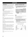
WARNING
TO REDUCE
THE
RISK OF FIRE OR ELECTRIC
SHOCK, DO NOT EXPOSE
OR MOISTURE.
THIS
UNIT TO RAIN
This nnit is not disconnected
from the AC po'a.er
the temperature inside this unit rises, it may cause
fire, damage to this unit, and/or personal injury.
consmne
8
Do not operate this unit upside-down. It may
overheat, possibly causing damage.
Do not use force on switches, knobs and/or cords.
10 When disconnecting the power cord from the wall
outlet, grasp the plug; do not pull the cord.
11 Do not clean this unit with chemical solvents; this
might damage the finish.
Use a clean, dry cloth.
12 Only voltage specified on this unit must be used.
Using this unit with a higher voltage than specified
is dangerous and may cause fire, damage to this
unit, and/or personal injury. YAMAHA will not be
held responsible for any damage resulting from use
of this unit with a voltage other than specified.
13 To prevent damage by lightning, disconnect the
power cord and outdoor antenna from the wall outlet
during an electrical storm.
We Want You Listening
standby
mode. In this state, this nnit is designed
a very small quantity
to
of power.
FOR CANADIAN
CUSTOMERS
To prevent
shock, match vdde blade of plug to
electric
wide slot and fully insert.
This Class B digital
ICES-003.
apparatus
complies
with Canadian
IMPORTANT
Please record
below.
tile serial number
of this unit in the space
MODEL:
Serial No.:
The serial nnmber
is located
Retain this Owner's
reference.
Manual
on the rear of the unit.
in a safe place
for fimlre
For A Lifetime
YAMAHA and the Electronic Industries Assnciation's
Consumer
Electronics Group want ynu to get the most nut of your equipment
by playing it at a safe level. One that lets the snund come through
loud and clear without annoying blaring or distortion
and, most
importantly, without affecting your sensitive hearing.
III
on common operating
source as long as it is connected to the wall outlet, even
if this unit itself is turned oft'. This state is called the
Do not plug in this unit to a wall outlet until all
connections are complete.
===
16 Be sure to read the "TROUBLESHOOTING"
Do not cover this unit with a newspaper, tablecloth,
curtain, etc. in order not to obstruct heat radiation. If
7
9
opened for any reasons.
Since hearing damage frnn/lnnd
sounds is nflen
undeteclable
nntil it is tno late, YAMAHA
and the
Eleclrnnic
Industries
Eleclrnnics
Group
prolnn_ed
expnsure
Association's
l'ecnmnaend
fron/excessive
Cnnsumer
ynu to avoid
vnlnme
levels.
_,*_,_LISTENING
FEATURES
.............................................................
GETTING
STARTED ............................................
2
3
Supplied accessories ..................................................
3
Installing batteries in the remote control ................... 3
CONTROLS AND FUNCTIONS
.........................
4
Front panel .................................................................
Remote control ...........................................................
Using the remote control ...........................................
Front panel display ....................................................
Rear panel ................................................................
4
b
7
8
10
SPEAKER
SETUP ...............................................
Speaker placement ...................................................
Speaker connections ................................................
CONNECTIONS
..................................................
11
11
12
15
Before connecting components ................................
Connecting video components .................................
Connecting audio components .................................
Connecting the FM and AM antennas .....................
Connecting the power supply cord ..........................
Speaker impedance setting ......................................
Tutoring on the power ...............................................
AUTO SETUP .......................................................
Introduction ..............................................................
15
16
19
21
22
23
23
24
24
Optimizer microphone setup ....................................
Starting the setup .....................................................
PLAYBACK
..........................................................
24
25
30
Basic operations .......................................................
Selecting sound field programs ...............................
Selecting input modes ..............................................
FM/AM TUNING .................................................
30
32
36
38
Automatic and manual tuning ..................................
Presetting stations ....................................................
Selecting preset stations ...........................................
Exchanging preset stations ......................................
XM Satellite Radio TUNING ..............................
What is XM Satellite Radio? ...................................
XM Satellite Radio connections ..............................
XM Satellite Radio functions ..................................
Activating XM Satellite Radio ................................
Basic XM Satellite Radio operations .......................
XM Satellite Radio search modes ............................
38
39
41
42
44
44
44
45
46
47
48
Setting XM Satellite Radio preset channels ............ 51
RECORDING
.......................................................
54
SOUND FIELD PROGRAM
DESCRIPTIONS
...............................................
For movie/video sources ..........................................
For music sources ....................................................
55
55
57
ADVANCED
58
OPERATIONS
..............................
Selecting the OSD mode ..........................................
58
Using the sleep timer ...............................................
58
Manually adjusting speaker levels ........................... 59
SET MENU ............................................................
60
Using SET MENU ...................................................
62
1 SOUND MENU ....................................................
63
2 INPUT MENU ......................................................
68
3 OPTION MENU ...................................................
70
ADVANCED
SETUP MENU ...............................
72
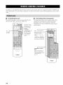
REMOTE CONTROL FEATURES ................... 74
Control area .............................................................
74
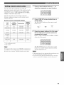
Setting remote control codes ...................................
Controlling other components .................................
Switching library codes ...........................................
Clearing set up remole control codes .......................
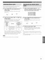
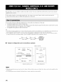
ZONE 2 (U.S.A., CANADA, AUSTRALIA,
U.K. AND EUROPE
MODELS ONLY) .........
Zone 2 connections ..................................................
75
76
77
77
78
78
Remote controlling Zone 2 ......................................
79
EDITING
SOUND FIELD PARAMETERS
......
What is a sound field ...............................................
Changing parameter settings ...................................
SOUND FIELD PARAMETER
DESCRIPTIONS
...............................................
TROUBLESHOOTING
.......................................
RESETTING
THE FACTORY
PRESETS
........
GLOSSARY ...........................................................
Audio formats ..........................................................
Sound field programs ...............................................
Audio information ...................................................
Video signal information .........................................
SPECIFICATIONS
...............................................
81
81
81
83
88
93
94
94
95
95
96
97
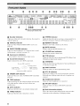
Built-in 7-channel power amplifier
Other features
•
•
YPAO:
(0.06% THD, 20 Hz to 20 kHz, 8 _)
Front: 95 W + 95 W
•
Optinfizer for automatic speaker
192-kHz/24-bit
D/A converter
Center:
•
A SET MENU
Minimum
RMS
output
po'a.er
95 W
Surround:
95 W + 95 W
Surround
back: 95 W + 95 W
optimizing
Sound field features
•
Proprietary
YAMAHA
sound fiekts
•
Dolby
•
DTS/DTS-ES
Matrix
DTS 9(,/24 decoder
Digital/Dolby
technology
Digital
•
Dolby
•
Dolby Pro Logic IIx decoder
Virtual CINEMA DSP
•
SILENT
CINEMA
for tile creation
of
EX decoder
6.1, Discrete
Pro Logic/Dolby
Pro Logic
6.1
DTS Neo:6,
Sophisticated AM/FM tuner
40-station
random
•
Automatic
preset tuning
•
Preset station
XM Satellite
•
and direct
shitting
preset
capability
tuning
(preset
Parametric
that provides
Room
8 additional
•
PURE DIRECT
PCM sources
•
On-screen
unit
•
S-video
•
Component
•
Video signal
conversion
--> Component
video)
you with items for
input jacks
for discrete
tUr pure fidelity
display
function
signal input/output
helpfld
input
with analog
in controlling
and
this
capability
video input/output
and coaxial
system
multi-channel
sound
capability
(Composite
capability
•
Optical
•
Sleep timer
•
Cinema
and music night listening
•
Remote
control
•
Zone 2 custom
Australia,
Acoustic
setup
this unit for your audio/video
•
IX/
TM
•
YAMAHA
digital
video
out
audio signal jacks
modes
with preset remote
control
installation
(U.S.A.,
U.K. and Europe
+-> S-video
for monitor
facility
models
codes
Canada,
only)
editing)
Radio
XM Satellite Radio programming (using the "XM
Connect and Play digital antenna accessory", sold
separately)
• -"_;'-indicates a tip for your operation.
• Some operations can be perlkwmed by using either the buttons on the main unit or on the remote controh In cases when the button
names differ between the main unit and the remote control, the button name on the remote control is given in parentheses.
• This manual is printed prior to production. Design and specifications are subject to change in part as a result of improvements,
case of differences between the manual and product, the product has priority.
etc. In
[111_
D_GITAL,
EX
Manufactured under license lhonl Dolhy Laboratories.
"Dolby', "Pro Logic". "Surround EX". and the double-D symbol
are trademarks nf Dnlby Laboratories.
"DTS'. "DTS-ES'.
"Neo:6" and "DTS 96/24" are trademarks of
Digital Theater Systems. Inc.
SILENT °
CINEMA
"SILENT CINEMA" is a trademark of YAMAHA
CORPORATION.
READY
The XM name and related logos are registered trademarks of XM
Satellite Radio Inc.
2
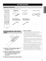
Please
check that you received
Remote control
all of the following
parts.
Batteries (4)
(AAA, R03, UM-4)
AM loop antenna
Optimizer
microphone
©U©5
q? Q q9 _
Indoor FM antenna
(U.S.A., Canada, China,
Asia and General models)
Indoor FM antenna
(U.K., Europe, Australia
and Korea models)
OYANAHA
aNN NNaNNaia
Notes on batteries
• Change :dl of tile batteries il' you notice tile l'ollowing
conditions: tile operation range of tile remote control decreases.
tile indicator does not flash or its light becomes dim.
• Do not use old batteries together with new ones.
• Do not use different types of batteries (such as alkaline and
manganese batteries) together. Read tile packaging carefully as
these different types of batteries m:q have the same shape aiM
color.
• If the batteries have leaked, dispose of them immediately. Avoid
touching the leaked material or letting it come into contact with
clothing, etc. Clean tile battery compartment thoroughly bel'_re
installing new batteries.
• Do not throw :_way batteries with general house waste: dispose
of them correctly in accordance with your local regulations.
If the remote
2 minutes,
remote
Press the _;_ part and slide the battery
compartment cover off.
control
is without
or if exhausted
control,
the contents
cleared.
When the memory
batteries,
set up the remote
any acquired
functions
batteries
batteries
for more than
remain
of the memory
is cleared,
control
in the
may be
insert new
code and program
that may have been cleared.
Insert four supplied batteries (AAA, R03,
UM-4) according to the polarity markings
(+/-) on the inside of the battery
compartment.
3
Slide the cover back until it snaps into place.
3
e
®
_'_ (U.S.A., Canada,
Australia, U.K. and
Europe models only)
O
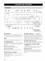
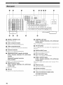
STANDBY/ON
•
PRESET/TUNING/CH*
<1 It>,
LEVEL-/+
Turns on this unit or sets it to the standby mode. When you
Selects
turn on this unit, you "a,ill hear a click and there
displayed next to the band indication in the front panel
display when the unit is in tuner mode. Selects the tuning
to 5-second
delay before
this unit can reproduce
"a,ill be a 4
sound.
preset
frequency
Adjusts
In standby mode, this unit consunms a small amount of power in
order to receive infrared-signals l'ron/the remote control.
O OPTIMIZER
MIC jack
Use to connect and input audio signals from the supplied
microphone for use with the AUTO SETUP flmction (see
page 24).
O Remote control sensor
station
number
1 to 8 when the colon (:) is
when the colon (:) is not displayed.
the level of the speaker
A/B/C/D/E
(NEXT)
channel
selected
using
when the unit is not in tuner mode.
O MEMORY (MAN'L/AUTO FM)
Stores a station in the memory. Hokt down this button for
more than 3 seconds to start automatic preset tuning.
O TUNING MODE (AUTO/MAN'L
DISPLAY
MONO),
Receives signals from the remote control.
S'a,itches tile tuning mode bet'a,een automatic (AUTO
indicator on) and manual (AUTO indicator off).
•
O
Front panel display
Sho'a,s information about the operational status of this
unit.
0
AIBIClDIE,
NEXT,
Selects the speaker
not in tuner mode.
4
channel
groups
to be adjusted
AUX
jacks
source
such as a game console.
signals from these jacks,
source.
CATEGORY"
Selects one of the 5 preset station
the unit is in tuner mode.
VIDEO
Input audio and video signals
(A to E) when
when the unit is
from a portable
To reproduce
select V-AUX
external
source
as the input
4,p],VlI;{,]Ir....f_I,VpI_i#I,Lr_.jrI[OILVl-
•
@ VOLUME
Controls tile output level of all audio channels.
This does not affect the REC OUT level.
U.S.A., Canada, Australia, U.K. and
Europe models only
_1 ZONE ON/OFF buttons
•
C'_ PHONES
Outputs
audio
(SILENT
signals
CINEMA)
for private
headphones.
When you connect
are output
to the PRE OUT jacks
jack
listening
headphones,
SPEAKERS
set of front speakers
on the rear panel each time the
_)
the function
(LEVEL
-/+)
to tile A
(EDIT),
SEARCH
selecting
preset
tile component
ill
this unit's
operation
room (Zone
to control
tile component
ill
2) (see page 79).
' Available only when the unit is in the XM Satellite Radio
MODE*
of PRESET/TUNING/CH
between
to control
mode (see page 45).
is pressed.
PRESET/TUNING
Switches
conuected
operation
2
the second
and/or
button
ZONE
Switches
A/B
B ternlinals
this unit's
the main room (see page 79).
are mixed down
Turns on or oft'tile
corresponding
Switches
no signals
or to the speakers.
All Dolby Digital and DTS audio signals
to the left and right headphone
channels.
O
MAIN
w,ith
<1 / C>
station
numbers
and tuning.
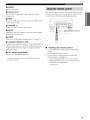
•
STRAIGHT
(EFFECT)
S'a, itches tile sound fields
selected,
output
input signals
directly
off or on. When STRAIGHT
(2-channel
or multi-channel)
from their respective
speakers
is
are
without
effect processing.
_) FM/AM, XM*
Sv,,itches the reception band "a,heu tile unit is ill tuner
mode.
@
PROGRAM
Use to select sound field programs
balance
•
(in conjunction
TONE
tile bass/treble
right, center,
presence
_)
bahmce
and subwoofer
INPUT
(AUTO,
when one component
received
or more of this unit's
@ INPUT
(see
DTS, ANALOG)
input jacks
for the type of
is connected
to two
(see page 36).
selector
tile input source you want to listen to or watch.
_1 MULTI
CH INPUT
the source conuected
jacks. When
priority
selector
channels
MODE
signals
Selects
for tile front left and
31 ).
Sets the priority
Selects
CONTROL).
CONTROL
Use to adjust
pages
or adjust tile bass!treble
with TONE
selected,
to tile MULTI
CH INPUT
the MULTI CH INPUT
source takes
over the source selected with INPUT
buttons on the remote control).
(or the input
@ PURE DIRECT
Turns on or off PURE DIRECT mode (see page 35).
5
I[I,[O]_TII:{O]IF,.'Jr_'y_T/IJ:I]_T[tlI[O]_T[_
This section
remote
describes
control
the function
components,
used to control
see "REMOTE
of each control
this unit. To operate
CONTROL
on the
O
other
Outputs
FEATURES"
on
Infrared
window
infrared
component
control
signals.
Aim this "a,indo'a, at the
you want to operate.
page 74.
CODE
@
SET
Use to set up remote
control
codes
(see page 75).
t¸
Input
...........
©
POWER
.0,_.,=] .............................
.
POWER
(_r,_DIs'_ [r'ow_Rj
......
CD
MD/CB,-R
selector
•
Sound
field
and change
the control
program/numeric
area.
buttons
TUNEtt_
Use to select
.......
© °U
@, ............
vcR_ DVn_VCR2
¢_,::
[© oo
buttons
Select the input source
......
sound
field programs.
Use numbers 1 through
unit is in tuner mode.
Use SELECT
8 to select preset
to playback
2-channel
stations
sources
channel format (see page 34).
Use EXTD SUR. to switch between
when the
in multiple
5.1 or 6.1/7. l-channel
playback of nmlti-channel
software (see page 33).
Use PURE DIRECT to turn on or off PURE DIRECT
mode (see page 35).
TVNUTE
D
TU E_PUT
Q
SPEAKERS
A/B
Use to turn on or off the set of front speakers
O
.............
the A and/or
B terminal
corresponding
button
LEVEL,
Selects
level.
O
Switches
mode.
.......
O
is pressed.
channel
the reception
buttons/,,
to be adjusted
and sets the
band when the unit is in tuner
/ v
/ < / ;,/ENTER
Use to select and adjust sound field program
SET MENU items.
N_CSKm
Press { / ) to select a preset station
the unit is in tuner mode.
group
Press/x
/ v to select a preset station
when the unit is in tuner mode.
parameters
(A to E) when
number
(1 to 8)
O RETURN, MEMORY"
Returns to the previous menu level when adjusting the
SET MENU parameters.
O TRANSMIT indicator
Fhtshes while the remote control is sending signals.
_J
@ STANDBY
Sets this unit in the standby mode.
SYSTEM POWER
Turns on the power of this unit.
6
to
BAND
the speaker
Cursor
connected
on the rear panel each time the
or
,,,_,p]=Vll;{e]_:_jF, y=Vpl_il]=V[e.,jl[e]d
O
_- -
SLEEP
Sets tile sleep timer.
O
MULTI
multi-channel
decoder
(etc.).
•
The remote
CH IN
Selects
input "a,hen using an external
control
transmits
Be sure to aim the remote
control
sensor
a directional
control
directly
on the main unit during
infrared
beam.
at the remote
operation.
AMP
Selects
the AMP mode. You must select the AMP mode to
control
the main unit.
O VOLUME +/Increasesor decreases tire vohnne level.
@ MUTE
Approximately 6 m (20 ft)
Mutes the sound.
the previous
O
Press again to restore the audio output
volume
level.
NIGHT
Turns on or off the night listening
_)
to
STRAIGHT
Switches
(EFFECT),
the sound fields
modes
(see page 35).
ENT.*
off or on. When STRAIGHT
is
selected, input signals (2-channel
or multi-channel)
are
output directly from their respective
speakers without
effect processing.
@ SET MENU, SRCH MODE*
Activates the SET MENU function.
Available only when the unit is in the XM Satellite Radio
mode/see page 45).
Handling the remote control
Do not spill "a,ater or other liquids on tire remote
control.
Do not drop the remote control.
Do not leave or store the remote
following
types of conditions:
-
places
of high humidity,
-
high temperatnre,
-
extremely
control
in the
such as near a bath
such as near a heater or stove
low temperatures
dusty places
7
(U.S.A., Canada, Australia,
and Europe models
only)
U.K.
O Decoder indicators
When any of this unit's decoders fimction, the respective
indicator lights up.
@ STEREO indicator
Lights up when this unit is receiving a strong signal for all
FM stereo broadcast w&ile tile AUTO indicator is lit.
O VIRTUAL indicator
Lights up when Virtual CINEMA DSP is active (see
page 36).
• MEMORY indicator
Fhtshes to show that a station can be stored.
O SILENT CINEMA indicator
Lights up when headphones are connected and a sound
field program is selected (see page 31 ).
• Input source indicators
A cursor lights to show the current input source.
• MUTE indicator
Flashes while the MUTE function is on.
@ VOLUME level indication
Indicates the current volume level.
•
PCM
Lights
O Sound field indicators
Light to indicate the activ*e DSP souud fields.
Modulation)
O
Presence DSP sound field
Left st r t _
DSP sound held
audio
PCM (Pulse Code
signals.
up when Surround
is selected
@
digital
STANDARD
Lights
/ -_ . Lislenin_ posilion
_[ , ): '}
Right surround
....
DSP sound hekl
indicator
up when this unit is reproducing
NIGHT
Lights
Standard
or Surround
Enhanced
(see page 34).
indicator
up when you select
night listening
mode.
Surround back DSP sound field
•
O
CINEMA
Lights
DSP indicator
up when you select
a CINEMA
DSP sound
field
program.
O
YPAO
Lights
up during
the auto setup procedure
settings
Both indicators
selected.
@
indicator
auto setup speaker
modifications.
SP A B indicators
Light up according
are used without
and w,hen tile
any
Headphones
Lights
selected.
are
indicator
up when headphones
are connected.
@ HiFi DSP indicator
Lights
up when yon select
O AUTO indicator
Lights up when this unit is in automatic tuning mode.
program.
O TUNED indicator
Shows
Lights up when this unit is tuned into a station.
information
8
to the set of t_ont speakers
light up when both sets of speakers
Multi-information
the current
sound
a HiFi DSP sound
field
display
field program
when adjusting
or changing
name and other
settings.
4,p],,_l l glo]lg,,..,7__
l,,q_,
ll gi#h,_
[_.*jl [olL,_
i- -
@
SLEEP
Lights
96/24
Lights
_)
indicator
up while the sleep timer
is on.
indicator
up w,hen a DTS 96/24
signal
is input to this unit.
LFE indicator
Lights
up when tile input signal
Input
Indicate
channel
indicators
tile channel
components
contains
tile LFE signal.
of tile current
digital
input signal.
•
U.S.A., Canada, Australia, U.K. and
Europe models only
ZONE
Lights
2 indicator
up w,hen Zone 2 po'a, er is on.
9
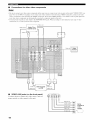
|I,[O]_TII:{O]IF,.'Jr__y_T/IJ:I]_T[tlI[O]_T[_
I"' 'A'm°Oe"i
]
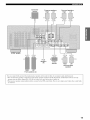
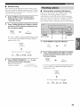
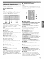
O DIGITAL OUTPUT jacks
See page 19 for details.
O Audio component jacks
See page 19 t_r connection information,
O Video component jacks
See pages 16 and 18 for connection int_rmation.
• Antenna terminals
See page 21 for connection information.
PRESENCE/ZONE 2 speaker terminals
(U.S.A., Canada, Australia, U.K. and Europe
models)
PRESENCE speaker terminals
(other models)
See page 13 for connection information.
O REMOTE IN/OUT jacks
(U.S.A., Canada, Australia, U.K. and Europe
models only)
•
CONTROL OUT jack
(U.S.A., Canada, Australia, U.K. and Europe
models only)
This is a control expansion terminal for commercial use.
• AC OUTLET(S)
Use to supply power to your other A/V components (see
page 22).
@ DIGITAL INPUT jacks
See pages 16, 18 and 19 for details.
• MULTI CH INPUT jacks
See page 17 for connection information.
O ZONE 2 OUTPUT jacks
(U.S.A., Canada, Australia, U.K. and Europe
models only)
These jacks output analog signals only. See page 78 for
details.
@ PRE OUT jacks
See page 20 for connection information.
See page 78 for details.
O XM jack
See page 44 for connection information.
• Speaker terminals
See page 13 for connection information.
•
Asia and General
models
VOLTAGE SELECTOR
See page 22 for details.
10
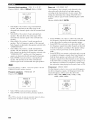
only
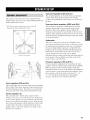
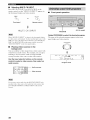
Surround speakers (SR and SL)
Tile surround
sounds.
The speaker
layout below
shows the standard
ITU-R*
speaker setting. You can use it to enjoy CINEMA
multi-channel
audio sources.
* ITU-R is tile radio communication
(International Telecommunication
DSP and
speakers
are used for effect
Place these speakers
position, facing
the floor.
slightly
inwards,
back
The surround
back speakers
Union).
speakers
and provide
about
1.8 in (6 tl) above
supplement
the surround
for more realistic
Place these speakers
listening
position
speakers.
They should
apart. Ideally,
and surround
your listening
speakers (SBR and SBL)
Surround
sector of tile ITU
transitions.
behind
front-to-back
directly
behind
and at the same height
be positioned
the
as the surround
at least 30 cm (12 in)
they should be positioned
at the same width
as the front speakers.
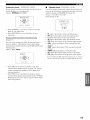
Subwoofer
The use ofa
subwoofer,
Servo Processing
,.
_!i;;
for reinforcing
;;_¸¸¸¸¸¸¸
critical,
because
directional.
not only
from any or all channels,
included
The position
Active
is effective
reproduction
effect) channel
DTS software.
30 cm (12 in) or more
System,
bass frequencies
but also t_r high fidelity
frequency
such as the YAMAHA
Subwoofer
of the LFE (lowin Dolby
Digital
of the subwoofer
low bass sounds
and
is not so
are not highly
But it is better to place the subwoofer
front speakers. Turn it slightly toward
room to reduce wall reflections.
near the
the center of the
speakers (PR and PL)
Presence
Presence
speakers
speakers
with extra ambient
supplement
the sound
from the front
effects produced
by CINEMA
DSP (see page 55). These effects include sounds that
filmnmkers
intend to locate a little farther back behind the
screen
in order to create
these speakers
(1 - 3 ft) outside
inwards,
more theater-like
ambience.
at the front of the room about
the front speakers,
and about
facing
1.8 m (6 It) above
Place
0.5 - 1 m
slightly
the floor.
Front speakers (FR and FL)
The front speakers
effect sounds.
are used for the main source sound
Place these speakers
an equal distance
plus
from
the ideal listening position. The distance of each speaker
from each side of the video monitor should be the same.
Center speaker (C)
The center speaker
(dialog,
vocals,
to use a center
however,
is for the center channel
etc.). If for some
speaker,
are obtained
reason
you can do without
it. Best resnlts,
with the flfll system.
Align the front
face of the center speaker
with the front face of your video
monitor.
Place the speaker
speakers
and as close to the monitor
directly
sounds
it is not practical
centrally
between
the front
as possible,
such as
over or under it.
11
IPIi/_Y+f-IiFb'iI_I"
5
Be sure to connect the left channel
"+" (red) and "-" (black) properly.
faulty, no sound will be heard from
polarity of the speaker connections
will he unnatural and Jack bass.
Tighten the knob to secure the wire.
(L), right channel (R),
If the connections are
the speakers, and if the
is incorrect, the sound
[_allll[oIAvi
•
If you will use 4 or 6 ohm speakers,
be sure to
set this unit's speaker
impedance
setting to
4 ohms
•
before
using
connecting
power
of this unit is off.
•
Before
tile speakers,
Do not let the bare speaker
not let them touch
could damage
•
rnnning
shielded
still creates
is colored
with a stripe,
groove
Open the tab.
2
Insert one bare wire into the hole of each
terminal.
)
3
Return the tab to secure the wire.
Remove approximately
cables
or shaped
or ridges.
etc.) cable to the "+" (red)
Connect
the plain
2
10 mm (3/8") of
insulation from the end of each speaker
cable.
2
1
with the monitor,
a pair of insulated
terminals on this unit and your speaker.
cable to the .... (black) terminals.
1
2 or
away from the monitor.
the striped (grooved,
10 mm (3/I
Connecting to PRESENCE/ZONE
PRESENCE speaker terminals
If this type of
the interference
cord is actually
perhaps
•
speakers.
speakers.
side by side. One cable
differently,
Connect
wires touch each other or do
this nnit and/or
place the speakers
A speaker
make sure that the
any metal part of this unit. This
Use magnetically
speakers
Red: positive
(+)
Black: negative (-)
(see page 23).
•
Banana plug connections
(With the exception of U.K., Europe and Asia models)
First, tighten the knob and then insert the banana plug
connector into the end of the corresponding terminal.
Twist the exposed wires of the cable together
to prevent short circuits.
3
Unscrew the knob.
4
Insert one bare wire into the hole in the side
of each terminal.
Banana
plug
(Withthe exceptionof U.K+,Europe
andAsia models)
You can also use banana plugs with the PRESENCE/ZONE 2 and
PRESENCE speaker terminals. Open the tab. then insert one
banana plugconnector intu the hole of each termiuah Du not
attempt to close the tabs after cunnecting the banana plugs.
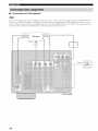
12
Subwoofer
system
(U.S.A.
Presence speakers
Right
Left
Surround speakers
Right
Left
model)
7
Front
speakers
(B)
10
8
Center
speaker
Right
Left
Surround back
speakers
Right
Left
Front speakers (A)
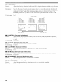
You can connect both surround back and presence speakers to this unit. but they do not output sound simultaneously.
• The surround back speakers output the surround back channel included in Dolby Digital EX and DTS-ES software and only
operate when the Dolby Digital EX. DTS-ES or Dolby Pro Logic llx decoder is turned on.
• The presence speakers output ambient effects created by the DSP sound fields. They do not output sound when other sound fields
are selected.
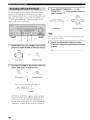
13
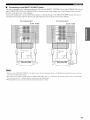
•
FRONT terminals
Connect
one or t'a,o speaker
systems
terminals. If you use only one speaker
to the FRONT A or B terminals.
•
(6, 7) to these
system,
connect
it
CENTER terminals
Connect
•
a center
speaker
(8) to these ternfinals.
SURROUND terminals
Connect
surround
speakers
3
(4, 5) to these terminals.
•
SUBWOOFER
jack
Connect a subwoofer "a,ith built-in amplifier (1), such as
the YAMAHA Active Servo Processing Subwoofer
System, to this jack.
•
SURROUND
Connect
surround
If you only connect
7
BACK terminals
back speakers
one surround
(9, 10) to these terminals.
back speaker,
connect
it
to the left (L) terminals.
•
PRESENCE terminals
Comlect
presence
speakers
(2, 3) to these terminals.
If you are using either the U.S.A.. Canada. Australia. U.K. or
Europe model, you can also use these speakers as Zone 2
speakers/see page 78).
14
Speaker layout
Dust protection
cap
Pull out the cap from the optical jack before
the fiber optic cable.
Do not discard
not using the optical jack,
[_MM [o]; j
place. This cap protects
Do not connect
this unit or other components
power until all connections
between
you connect
the cap. When you are
be snre to put the cap back in
the jack from dust.
to the mains
components
are
complete.
•
Cable indications
For analog
signals
•
jacks
Video
left analog cables
_IIIL
This unit has three
right analog cables
_1_
depends
The signals
For digital
-,,,,,,,,,,,,,,,,_ d_o ' _
signals
coaxial cables
:,{_[
input through
through
the S VIDEO
Likewise,
For video signals
video cables
_':
input through
Connection
of input jacks on your monitor.
the S VIDEO
jacks
signals
also be output
t[5_J
the VIDEO
input through
through
jacks
can be output
and COMPONENT
VIDEO
the S VIDEO
the COMPONENT
component
•
,iUg'.i
VIDEO
@
signals
from andio components
This unit has digital
through
jacks for direct
either
coaxial
can use the digital jacks
DTS bitstreams.
the COAXIAL
the input signals
¥
@@@
transmission
COMPONENT VIDEO jacks
For component signals, separated into hnninance (Y) and
color difference (Pro Pk) to provide the best quality in
picture reproduction.
to input PCM, Dolby
and OPTICAL
jacks,
priority
with 96-kHz
You
Digital
components
from the COAXIAL
input jacks are compatible
of digital
or fiber optic cables.
When you connect
S VIDEO jacks
For S-Video signals, separated into luminance (Y) and
color (C) video signals to achieve high-quality color
reproduction.
on this unit.
Digital jacks
signals
VIDEO
p_
and white plugs to the
audio pin cable to the analog jacks
red plugs to the right jacks
by
left jacks.
•
can
jacks.
VIDEO jacks
For conventional composite video signals.
Analog jacks
Connect
@
p_
jacks.
video cables
You can input analog
connecting
SW_EO
jacks
VIDEO
COMPONENT
S-video cables
on this unit
are automatically
converted for output through the VIDEO
jacks. When VIDEO CONV. is set to ON (see page 70),
signals
optical cables
types of video jacks.
on the availability
and
to both
is given to
r- .....................................................................................................
Output
(MONITOR OUT)
jack. All digital
sampling
,
Signal flow inside this unit
Input
digital
.............
signals.
....-;;7.'"
This unit handles digital and analog signals independently. Thus
audio signals input to the analog jacks are only output to the
analog OUT (REC).jacks. Likewise audio signals input to the
digital (Ot_ICAL or COAXIAL) jacks are only output to the
DIGITAL OUTPI JT .jack.
S V_DEO
VIDEO
__
When signals are input through both the S VIDEO and VIDEO
.jacks, signals input through the S VIDEO.jack have priority.
15
|_'tllll_qlPtl_
•
Connections for DVD playback
Be sure to connect your video source components in the same way you counect your video monitor to this unit if VIDEO CONV. (see
page 70) is set to OFF. For example, if you connect your vide() monitor to this unit using a VIDEO connection, connect your video
source components to this unit using the VIDEO connections. (Even when VIDEO CONV. is set to OFF. S-video signals input from
your video source component are automatically converted to composite signals in this unit.)
[
Coaxial
out
Oplica]
out
Video oul
DVD player
Audio
oul
!7
_Z
L
J
Vide() in
7ZZZZZZZZS7
(U.S.A.
16
model)
•
Connecting to the MULTI CH INPUT jacks
This unit is equipped
right SURROUND
vdth 8 additional
BACK
decoder,
sound
Connect
the outpnt
processor
input jacks
and SUBWOOFER)
(left and right FRONT,
for discrete
CENTER,
multi-channel
left and right SURROUND,
input from a multi-format
or pre-amplifier.
jacks on your nmlti-fonnat
match the left and right outputs
player or external
decoder
to the MULTI
to the left and right input jacks for the front and surround
For 6-channel input
CH INPUT
o.,
j
Multi4ormat player/
[
External decoder [ Surround
j om
Be sure to
For 8-channel input
(U.S.A. model)
Stbw,
|
jacks.
channels.
(U.S.A. model)
om
left and
player, external
l 0
U
fer
Multi-format player/I
R_
:SUl}al/ind
Fron_ I External decoder Lbackout
out
L
j Surround
()ill
No es;;
• When you select MULTI CH INPUT as the input source, this unit automatically turns off the digital sound field processor, and you
cannot select sound field programs.
• This unit does not redirect signals input to the MULTI CH INPUT jacks to accommodate for missing speakers. We recommend that
you connect at least a 5.l-channel speaker system before using this feature.
• When headphones are used. only front left and right channels are output.
17
II'loti'li'l_'llPti'_
•
Connections for other video components
• Be sure to connect yuur video source componeuts in tile same way you connect your videu monitor to this unit if VIDEO CONV. (see
page 70) is set tu OFF. Fur example, if yuu connect your video mouitur to this unit using a VIDEO connection, connect your video
source cumpouents to this unit using the VIDEO connections. (Even when VIDEO CONV. is set to OFF. S-video signals input from
your videu source component are automatically converted to cumposite signals in this unit.)
• Converted video signals are only output to the MONITOR OUT jacks. When recording you inust make the same type of videu
connections/i.e..
S-videu) between each component.
LVideo
I
Optical
o
Cable
ouq
TV
Otll
or
-[_ate.ite tunerh
E
g
I
f Audio ou'7_,_
'
Ut
Video in
(U.S.A.
model)
•
VIDEO AUX jacks (on the front panel)
Use these iacks to connect any video source, such as a
game console or video camera, to this unit.
l
_l l
_
Audio out R _1
Game
Audio
out L
Opiicaloul
console or
Video oul
cViadge°ra
S-video out
18
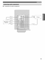
_otl,h,l_lptl, i--
•
Connections for audio components
Audio out
Optical in
CD player
I
MD recorder
Optical oul
or
tape deck
Coaxia]
Audio
oul
in
(U.S.A,
model)
19
INqI'M=PtlPh'_
•
Connecting to an external amplifier
If you "a,ant to increase
tile power output
to the speakers,
or want to use another
amplifier,
an external
amplifier
to the PRE OUT jacks
connect
as follows.
• When audio pin plugs are connected to the PRE OUT jacks for
output to an external amplifier, do not make connections to the
corresponding SPEAKERS terminals. Set the volume of the
amplifier connected to this unit to the maximum.
• The signals output through the FRONT PRE OUT and
(-?ENTER PRE OUT jacks are affected by the TONE
CONTROL settings.
• If SPEAKERS A is turned off and SP B is set to ZONE B (see
page 711, signals will only be output [nnn the FRONT PRE
OUT jacks.
O FRONT PRE OUT jacks
Front channel line output jacks.
O SURROUND PRE OUT jacks
Surround channel line output jacks.
O CENTER PRE OUTjack
Center channel line output jack,
• SURROUND BACK PRE OUT jacks
SurromM back or presence channel line output jacks.
O SUBWOOFER PRE OUT jack
Comlect a subwoofer "a,ith built-in amplifier, such as the
YAMAHA Active Servo Processing Subwoofer System,
to this jack.
• Each PRE OUT.jack outputs the same channel signals as the
corresponding speaker terminals.
• A;ljust the volume level of the subwuofcr with the control on
the subwoofer. It is also possible to atljust the volume level
using the remote control (see "Malmally a_[justing speaker
levels" on page 59).
• Some signals may not be output from the SUBWOOFER PRE
OUT.jack depending uu the SPEAKER SET/see page 63) and
LFE/BASS OUT (see page 64) settings.
20
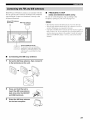
Both FM and AM indoor antennas
unit. In general,
these antennas
signal
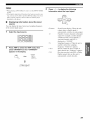
Connect
strength.
designated
are included
with this
should
provide
sufficient
each antenna
correctly
to the
•
FREQUENCY STEP
(Asia and General models only)
Be sure to set the frequency
terminals.
frequency
spacing
step according
to tile
in your area (see page 73).
Indoor FM antenna
(included)
AM loop antenna
(included)
• Tile AM loop antenna shouM be placed away from this unit.
• The AM loop antenna shoukl always be connected, even if an
outdoor AM antenna is connected to this unit.
• A properly installed outdoor antenna provides clearer reception
than an indoor one. If you experience poor reception quality, an
outdoor antenna may improve the quality. Consult the nearest
attthorized YAMAHA dealer or service center about outdoor
antemmg.
Ground (GND terminal)
For maxilnmn safety and minimum
interti_rence, connecl the antenna GND
lerminal to a good earth ground. A good
earth ground is a nlctal slake driven into
moist earth.
Connecting the AM loop antenna
1
Set up the AM loop
to the terminals
antenna,
then
connect
it
on this unit.
Press and hold the tab to
insert the AM loop antenna
lead wires into the AM ANT
and GND terminals.
Orient the AM loop antenna
for the best reception.
21
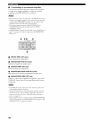
INqI'M=PtlPtff
•
Connecting
the AC power cord
•
Plug tile power cord into an AC wall outlet.
•
AC OUTLET(S) (SWITCHED)
U.K. and Australia
...................................
1 outlet
Korea model
..............................................................
None
Other
........................................................
models
Use these outlets
models
to connect
other components
OUTLET(S)
is controlled
(or SYSTEM
POWER
supply
to any connected
power
unit is turned
(total power
•
to the AC
by this unit's
STANDBY/ON
and STANDBY).
The outlet(s)
component
on. For information
consumption
"SPECIFICATIONS"
whenever
on the maximum
of components),
this
power
see
on page 97.
VOLTAGE SELECTOR
(Asia and General models only)
Tile VOLTAGE
SELECTOR
on tile rear panel of this nnit
must be set for your local main voltage
BEFORE
into the AC main supply. Voltages are:
Asia model .........................
220/230)-40
General
model
..... 110/120/220/230
VOLTAGE
SELECTOR
(Asia and General
22
2 outlets
the power cords from your
to this unit. Power
models)
Memory back-up
Tile memory
plugging
V AC, 50/60 Hz
240 V AC, 50/60 Hz
back-up
circuit
prevents
the stored data from
being lost even if this unit is in the standby
mode.
However
from the AC
if the power cord is disconnected
wall outlet, or the power supply is cut for more than one
week, the stored data will be lost.
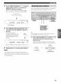
When all connections
this unit.
[_: !ll/_olAvl
If you are using 4 or 6 ohm speakers,
4 or 6 ohms as follows
before
set the impedance
turning
Be sure this unit is in the standby
are complete,
turn on the power of
to
on the power.
mode.
Turn off the power to this unit, and while
holding down STRAIGHT (EFFECT), press
STANDBY/ON.
This unit turns on, and the ADVANCED SETUP
menu appears in the front panel display.
(U.S.A.
model)
S"rRAI_HT
While holding
down, press
Rotate PROGRAM to move through
and select "SP IMP.".
the menu
PROGRAM
1
3
Press STANDBY/ON (or SYSTEM POWER on
the remote control) to turn on the power of
this unit.
Press STRAIGHT (EFFECT) repeatedly to
select "4 _) MIN".
or
Front panel
2
4
Press STANDBY/ON
The setting
unit's
power
control
Turn on the video monitor connected to this
unit.
to turn off the power.
you made is reflected
is turned
Remote
the next time this
on.
23
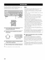
This receiver
Acoustic
employs
Optimizer
avoid troublesome
achieves
highly
optimizer
YAMAHA
(YPAO)
listening-based
accurate
microphone
your speakers
environnlent.
sound
collects
produce
Parametric
technology
Room
which lets you
speaker
setup
adjustments.
and analyzes
in your actual
and
The supplied
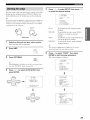
1
Connect the supplied optimizer microphone
to the OPTIMIZER MIC jack on the front
panel.
the sound
(U.S.A.
listening
model)
• Please be advised that it is normal for loud test tones to be
output during the auto setup procedure.
• If auto setup stops and error messages appear on the screen,
follow the troubleshooting on page 28.
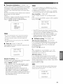
YPAO performs
appropriate
sound
the following
adjustments
checks
and makes
to give you the best possible
from your system.
WIRING:
Checks
which speakers
are connected
and the polarity
of
................................
• After you have completed
each speaker.
disconnect
• The optimizer
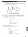
SIZE:
Checks
the speakers
crossover/high
frequency
cut frequency
the sound relationship
subwoofer.
response
and sets the
for the subwoofer
between
the speakers
and the
Checks the distance of each speaker from the listening
position and adjusts the delay of each channel so that the
sound from each speaker reaches the listening position at
the same time.
EQUALIZING:
Adjusts frequency and levels of each channel's parametric
equalizer to reduce coloration across the channels and
create a cohesive sound field. This is particularly
important if you use different brands or sizes of speakers
for some channels or have a room with unique sonic
characteristics.
YPAO equalizing calibration
parameters (frequency, level
seven bands in its parametric
precise automatic adjustment
the auto setup
microphone
Keep it away l'roul direct
Do not place
procedure,
be sure to
microphone.
is sensitive
to heat.
sunlight.
it on top of this unit.
to improve
DISTANCE:
incorporates three
and Q factor) for each of the
equalizer to provide highly
of frequency characteristics.
LEVEL:
Checks and adjusts the sound level (volume) of each
speaker.
24
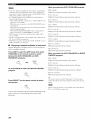
the optimizer
Place the optimizer microphone on a flat
level surface with the omni-directional
microphone head upward, at your normal
listening position.
If possible, use a tripod (etc.) to affix the optimizer
mic at the same height as your ears would be when
you are seated in your listening position.
Optimizer microphone
position
rPiP,l"/"ilq'l
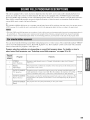
For best results,
during
make sure the room is as quiet as possible
the auto setup
much ambient
noise,
procedure
(YPAO).
the results
may not be satisfactory.
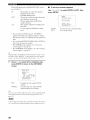
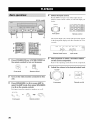
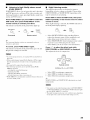
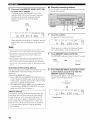
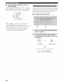
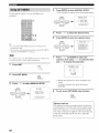
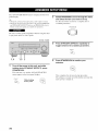
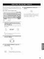
Press i / V to select SETUP, then press < / >
to select the desired setting.
If there is too
i
FAh,=F= I,+_FLIII
=i N+ ==B°
++ 5ETLIF', ......
START
W-if your
subwoo%r has a{[iustable volmne and crossovedhigh cut
frequency controls, set tile volume between 9 and 11 ofclock (as
viewed on a conventional clockface) and set tile crossovedhigh
nLITO
gluto+_stic
Fr c e:a:air,9
c4 .=Ai ite+_,s
[1]
['r]
UF Dc,url
[<], [>]:Seiect
cut frequency to the maximum.
OmOSSOVEm]
HIgH CUT
VOLUMB
r'_,..+,Fli
H"f",l
*...,
O
M_N
TO perfonn
the auto setup procedure
(YPAO).
Lr'<
i:::,i:::i
r.-,i'.,
i ',<L,,A,,,, %,q"_
To reload
settings
MAX
the last auto setup (YPAO)
to override
Subwoofer
,...,i
udr'.,r,_,....,...,
To undo the last auto setup (YPAO)
restore the previous
Switch on this unit and your video monitor.
Make sure the OSD is displayed.
,....u.,i"i:::i:::""i,...,...,_ii
"r', To restore
the factory
and
settings.
preset
(default)
setup parameters.
_.,#._
You can choose RELOAD or UNDO only if you ha',e
Press AMP.
_mp
Press
any manual
changes.
)
already performed the aulo setup procedure.
Press v to select "START", then press
ENTER to start the setup procedure.
The screen changes as follows.
SET MENU.
sfl m[t0
i
W-WhenMEMORY
GUARD is set to ON. you cannot select
any other SET MENU items (see page 60).
÷
,=1
+
FA i%== F,IIFF,b'
4'°'N+ ===,MF+,+,,,
I
FF
'_i
2Ci,,"F+q_,
.......
÷
=AI_ITCI c,,_'-c'r,,
k-'
@IAI4LIAL SETUF'
"SiGHAL
iilFCl,,
rE ¸¸
E
_
E
_
F,UTCI
Aut c,I,_at
ic
FYOC @:::,
:2i yI'_/
c4 +li item_
[1] [+] LIF 'Doun
[EHTER ]_E;t_# t
Press i / V to select AUTO SETUP, then
press ENTER.
pRESET
jet
N,++
UJ=HM,i'iU
FjUTF= + ++_K_
i l
SETUP, ......
5TF,R]
÷
IH!TiF, LZ !HG
id! F,:!HG
S!ZEiDiS;TANCE
EOUALIZIH{
LEUEL
C:HEC:K CH=CEIi]ER
IIIII
........
8_3:I ExiL
+
pll_i[/cl
F_F:=I ii T_ F=U?T
I,I:,LJLi =D"="i
IIARIIII/G
RESULT
,R_
SF' :
54g.. !
[:,!5;Y_!/;;i,,€_ !:2,,{Ift
Uq. : ---J,n +6,,fIB
'-ET L-AIIL-:EL
25
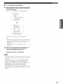
l_lql',l"b'ilq"
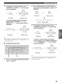
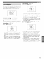
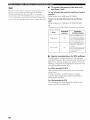
The results displayed
are as follows:
in the RESULT:EXIT
•
If an error screen
of connected
speakers
press ENTER.
displayed in the order:
Front/Back/Subwoofer
r", T ,::7"i"
I...' .l....+++
i iii
l...+v'l ....
The distance
of the speakers
unit displayed
in the order:
Closest
speaker
speaker
distance
The speaker
the order:
Lowest
level
• If you selected
appears
level displayed
level/Highest
in
i=H:7<T'_=,Lj
i'.<i,,. 1 I% {
output
AUTO
in step 5, "WAITING"
DEFAULT,
is started,
from each speaker
RELOAD
or UNDO
in
in
step 5, no test tones are output.
screen
screen
appears"
• If a WARNING
screen
appears"
appears,
see "If an error
on page 26.
screen
appears,
see "If a warning
on page 27.
"4+"Youcan
display tile detailed result information by using v and
ENTER tu select "RESULT". In the detailed result infurmation
screen, you can switch infurmation by pressing/x / v / < / ).
7
Press ( / > to select SET or CANCEL, then
press ENTER to return to the SET MENU
screen.
i,]glRlI! i4S <3)
RES;ULT
SF'
:
5/4/[i,,
!
DiS'r+
!@+g!
!2,,€+;t
LiJJ
-9,,g
+6.Sr_EI
-+ :SET
CI:IHCEL
[i] i[T]
Lli= Dc,_,l_/
EEI4TER ] sEnLe_
SE"[
To apply the auto setup (YPAO)
settings.
c'.c',i..+,-¢::i
To cancel
without
the auto setup (YPAO)
making
any changes.
--'4+'-If you are
nut satisfied with the result or 'vvaut 1o manually adjust
each setup parameter, use the manual setup parameters/see
page 59).
• If E-10 appears during testing, restart the procedure froln step 3.
• To cancel tile autu setup procedure before completiun, press A.
26
E+-9:, USER C:F/IICEL
i::7=...
_ T <'i"
then loud test tones are output
turn.
• If an ERROR
l_u,u, wu,
÷
output
output
b.b'b'i
Ib'
from this
distance/Farthest
when the auto setup procedure
• If you selected
appears
Use A / v / < / > to select RETRY or EXIT, then
The number
....,i
screen
?RETR','
EXIT
[±]
[_]
U_ [:,o+,+_+
rr_.....
_ r. !,
To retry the auto setup procedure.
To exit auto setup.
iffiP,l-'b'ilq'l
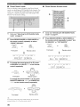
If a warning screen appears
1
Press ENTER to display detailed information
about the warning.
Press ( / > to switch between warning messages.
C,D:iii T_D,q=
i _ _r=i
R_wUi_
-* idF_IRiI!HG (3)
REE;ULT
SF' :
5'4/Ch, !
I:q:5r_ !_,,,,?' J2,,_?÷'_
)SET CPlICEL
Ill
'[_]
; LIp/[!oal_/
[EHTEP]: Enter
<OUT OF F'HFIS;E)
FL
CEHTER
F'L
F'F,:
SL
SR
EBL
5BR
[<] '[)]_Se!ect
[ EHTER ] _Pe{/,IP h
W-1 warning
For details
screen
about each message,
see page 29.
• Warnings let yuu know about potential problems detected
during auto setup. Warnings will not cancel the auto setup.
• The munber of warnings is displayed to the right of
"WARNING".
• When the warning is not applicable to a speaker, " -' is
displayed.
When you are finished, press ENTER to
return to the RESULT:EXIT screen.
Continue from step 7 on page 26.
• If yuu change speakers, speaker positions, or the layout of your
listening environment, perform auto setup again to re-calibrate
your system.
• Depending on listening environments. SWFR PHASE:REV
appears in AUTO:CHECK and SUBWOOFER PHASE
parameter in the SETMENU/see page 65) is automatically set
to REVERSE. To select the desired setting, change the
SUBWOOFER PHASE parameter in the SETMENU.
• In the DISTANCE results, the distance displayed may be longer
than the actual distance depending on the characteristics of your
subwoufer.
27
I_llil'/-'/-'/ll,I"
•
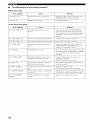
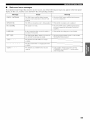
Troubleshooting
for auto setup procedure
Before auto setup
Error message
I :r',Fd'H:::,r'.'L
P'I I I :
Cause
Optimizer
microphone
is
Remedy
not
connecled.
•
Connecl
the
supplied
OPTIMIZER
Ui"!P
ii.i..4g
Headphones are connected.
HF'
optimizer
jack
MIC
on
microphone
the
Io
the
panel.
front
• Unplug the headphones.
Errors during auto setu
Error message
l..,=i::_'""
.l. • i..h"t
".%.,'i
l
li::_'EM"d"Fi"I".'...'I
".' _
....q'::'D
Cause
Front L/R channel
Remedy
signalls)
Select
Ihe front
speakers with SPEAKERS A/B.
• Check Ihe front left and right speaker conneclions.
• Turn on Ihe power to Ihe exlernal amplifier (when Ihe
is !arc) nol
•
delecled.
front
speaker
signals
are
Otltptll
frolil
an
external
amplifier).
i..,.i2_''"":'.=:..
,."li"il"".%.'F..":?i
....'*...'i E:,
F.. i.::.=:
....q'::'i'::'
l..,,i:F"""T,...'
" l".%.'i"il"lliDi:::'J:::"::FF.._........'
=: ....q'::'D
i..,.i::?""
H..r." ....._...,F..
,::?iD iD .._ ..'"'::7iD
..., i...q.i
Only_one
surround
channel
signa]_
is detected.
•
Check Ihe
Only one
l)resence
channel
signal is detected.
•
Check Ihe presence speaker connections.
•
(_onnecl
OnlY_ l'i _ht_
delecled.
stlrrotlnd
back channel
siKna]
is
speaker
stlrrotllld
Ihe
SLIITO Lind
SURROUND
BACK
conllectk)ns.
back speaker Io Ihe LEFT
SPEAKERS lerminal if you
only have one surround back speaker.
i..,.iZ
.....+::::+...,
." li"i+"l'.'*...,
.+.T
....+'::7+"il
B ack_rotllld_
noise
ix too
loud.
•
Try_
the
setup
al.lto
procedure
in {i quiel
environmenl.
• Turn off noisy elechic equipment like air condilioners
(elc.)
or
move
them
away
frolll
Ihe
oplimizer
microphone.
I,,,.i::7""*:::*,,,'
." ',,..I¢%"ii::7
¢%,"ii,,,.,....1...,,,*%,*'i',,'::Fi
ii:::, ::
Surrotlnd
Ihough
_..,.i::
"::'_
."_i"ir".-...,
_i"_
T._......r"
back
speaker(s)
is
(are)
surrotllld L/R speakers
surround
speakers
surround back speaker(s).
• Check Ihe surround speaker
COl]llected,
•
are nol.
The oplimizer microphone was unplugged
The
oplimizer
nol
detect
test
Iones.
1..,.i27""*:5...'
"' '...'....q..,.
F..iJ*:::'i27i:::. *....r".q
I"' tu'lH".'*....
I"' _....
11:7
ti...
i..,.1::7.i.
.'i t':a•
,:..*
.i. i..i"i"i:::'i:::,H
".q".qT
i "., _ I....F..I
l::_;i'i:;i'l'_ll:;?
28
¢"li....
The
aUtO
user
aclivity.
seltlp
procedtlre
A DSP COllllll[llliCalion
occu fred.
x_r_IS
cancelled
due Io
•
Check Ihe lllicrol)hone
Check Ihe speaker
•
Perforlll
•
the
VOLUME
error
you
use
(a)
connections.
auto setup procedure.
does
microphone
when
• Do nol Iouch Ihe optimizer microphone durin_ Ihe
during the auto setup procedure,
l..,=i::P
_...0,...,,."li"il"t',%.'...."::?
.I.T*...ul':2
i,.i
",q",q.....
¢"li
(_onnecl
or
hangtlp
•
Perform
ilulo
(etc.)
Ihe
auto
setting.
conneclions
setup
during
selup
and
again. Do
procedure
the
placen/ent.
atllo
1)rocedtlle
selup
again.
nol
procedure.
a(ljusl
illll'/-'/-'/ll, ffI
Warnings after auto setup
Press
( / ) to display
Warning
[.+J""
i ',',OU"[
detailed
infomaation
about
message
OF
individual
warnings.
Cause
[:::'H[::'4'.!!!;i![
Remedy
Speaker polarity is nol correcl. This message:
may appear depending on Ihe speakers even
when the speakers ;ire connecled correclly.
• Check Ihe Slx.akcr conncclions
(+ / ).
i._j""2 ',l(ili.Ji!!R 2=::i,f,'!
The distance belween the spe iker and the
listening posilion is 24 m (80 fl) or more.
• Move Ihe speaker closer Io the listening position.
• Check Ihe speaker conneclions
lk)r proper polarity
(+ / ).
'.'>'i'i""<':i
'<...,,."_...I..,:
I....ii:::"i'..><
i_:::'i
_...
The
I..,:I_:::,
i::"
'..Ii:::,
'.. i=i
'...'I_:::,
'..
dil [ereilce
is excessive.
of
voltln/e
level
(No level correclion
imong
spe
ikers
is made.)
•
Readjusl
the
speaker
are sel in localions
instalhllion
• If the ERROR
ur WARNING
• If warning
W-l
• It warning
W-2 or W-3 appears,
• If error E-IIl
appears,
occurs
screens
corrections
repeatedly,
appears,
are made.
i1(!corrections
please
contact
check
the cause
uf the problem,
then perform
so
that
all
speakers
wilh sililihlr condilions.
• Check Ihe speaker conneclions
(+ / ).
• Use speakers
l_)r prolx.r polarily
of similar
lk)r proper polarity
qualily and efficiency.
the auto setup
procedure
again.
but they may not be optimal.
are made.
a qualified
YAMAHA
service
center.
29
Select
the input source.
Rotate
(U.S.A.
model)
INPUT
buttons
desire.
(or press one of the input selector
on the remote
control)
to select
the input you
iNPUT
or
Front panel
1
3
7
4
The current
Remote
input source
control
name and input mode appear
in the front panel display
seconds.
and video monitor
for a few
1
#w,,u¢_
vc_l
4
I%
a
v At_x
#Tv,e_t
I I r".
i,_L._iJ
DVD
(or SYSTEM POWER on
the remote control) to turn on the power.
rouen
cD
PHONO
VOLU_aE
_m I I ._m m.
_.°iii i ii
Selectedinputsource
Press STANDBY/ON
_#_e#R
Input mode
Start playback or select a broadcast station
on the source component.
Refer to the operating instructions for the component.
POWER
or
Adjust the volume to the desired output level.
VOLUME
Front
panel
Remote
control
or
2
Turn on the video monitor connected to this
unit.
3
Press SPEAKERS A or B (or press AMP to
select the AMP mode, then press SPEAKERS
A or B on the remote control).
Each press turns the respective speakers on or off.
_PEAKER_
v,:'u _,
Frontpanel
30
or
_
Remotecontrol
",
Front
panel
Remote
control
•/_l_:_I'f,"I
•
Select
a sound
field
Use PROGRAM
program
(or press AMP to select
mode, then press one of the sound
buttons)
to select
I_r details
if desired.
You can adjust the tonal quality
of your front left and right,
center, and subwoofer
field program
a sound fiekt program.
about sound
the AMP
To adjust the tone
See page 55
headphones
(when
Press TONE
field programs.
speakers
TONE
OO,T_OL
or
connected).
CONTROL
on the
_,
front panel repeatedly
to select
TREBLE
or BASS, then rotate
PF_OGRAM
PROGRAM
PROGRAM
to the right or left to
increase or decrease.
•
Select TREBLE
high frequency
Front panel
•
Select BASS
frequency
or
•
CINEMA"
nmsic or movie
surround,
CINEMA"
headphones
through
activates
• When TONE BYPASS is set to "AUTO" (page 67), and BASS
and TREBLE are set to 0 dB. audio output automatically
bypasses this unit's tone control circuitry.
("SILENT
allows you to enjoy multi-channel
sound,
including
ordinary
to the PHONES
Dolby
headphones.
automatically
Digital
"SILENT
whenever
jack while
and DTS
you connect
listening
CINEMA
DSP or HiFi DSP sound field programs.
activated,
the "SILENT
CINEMA"
headphone adjustments are stored independently.
• TONE CONTROL is not effective during playback in the
PURE DIRECT mode. or when MULTI CH INPUT is selected
(page 32).
control
To listen with headphones
CINEMA")
"SILENT
to adjust the low
response.
-#Speakerand
Remote
to adjust the
response.
indicator
•
To mute the sound
Press MUTE
The MUTE
on the remote
indicator
flashes
control.
in the
front panel display.
to
When
lights up in
To resume
MUTE
The MUTE
the front panel display.
the audio output,
press
again (or press VOLUME
indicator
disappears
/+).
from
the display.
• This unit will not be set to "SILENT CINEMA"
when MULTI
-#Youcan
a@lst the muting level (see page 67).
CH INPUT is selected as tile input source.
• "SILENT CINEMA" is not effective when PURE DIRECT or
the 2ch Stereo program is selected, or in STRAIGHT
mode.
31
•
Selecting MULTI CH INPUT
Press MULTI
remote
CH INPUT
control)
(or MULTI
so that "MULTI
the front panel display
CH IN on the
CH INPUT"
appears
in
•
and video monitor.
MULTICH
INPUT
Front panel operation
NULT_CH N
%
or
Front panel
i...ii
I'H
Remote
ii
II
"i" T
1 1
r"q
i
I ,_"I
control
(U.S.A.
T i. ii"tl
i"i"
I u,Ir"
I 1 I
Rotate
When "MULTI CH INPUT" is shown in the front panel display,
no other source can be played. To select another input source with
INPUT (or one of the input selector buttons), press MULTI CH
INPUT (or MULTI CH IN on the remote control) to mrn off
"MULTI CH INPUT" in the front panel display.
Playing video sources in the
background
You can combine a video image from a video source with
sound from an audio source. For example, you can enioy
listening to classical nmsic while viewing beautiful
scenery from the video source on the video monitor.
model)
PROGRAM
PROGRAM
to select
The name of the selected
panel display
the desired
program
appears
program.
in the front
and video monitor.
PROGRAM
•
Use the input selector buttons on the remote
control to select a video source, then select an
audio source.
Audio sources
........................
Video sources
If you want to enjoy audio from the MULTI CH INPUT.jacks
together with a video source, first select the video source, then
press MULTI CH INPUT (or MULTI CH IN on the remote
control).
32
DWg_CR* VCm
VAUX
DIV,C_L
_P
_
_
D_D i _D,CD_
Program name
Ttmar4
CD
PHOnO
W,LVME
•/_ItF_PL"I
•
Remote control operation
•
Enjoying multi-channel
software
If yon connected a surround back speaker, use this feature
to enjoy 6.117.1 -channel playback for multi-channel
sources using the Dolby Pro Logic llx, Dolby Digital EX
or DTS-ES decoders.
Sound field
program
buttons
AMP
Press AMP to select the AMP mode, then press
EXTD SUR. on the remote control to switch
between 5.1 and 6.1/7.1-channel
5M_p'
Press AMP to select the AMP mode, then press
one of the sound field program buttons to select
the desired program.
The name of the selected program appears in the front
panel display.
¢
9V_'_
yen1
VmX
_Vm_L _ OW
Program
_ _D,_¢D_ IUNEr_
CD
r_HOHO
WLUME
name
playback.
EXTD SUR.
To select a decoder, press < / ) repeatedly when
PLIIxMusic (etc.) is displayed.
Auto (l::ii...iiO)
When a signal (flag) that can be recognized by the unit is
input, the unit selects the optimum decoder for playing
back the signal in 6.117.1 channels.
If the unit cannot recognize the flag or no flag is present in
the input signal, it cannot automatically be played in 6.11
7.1 channels.
Choose a sound field progranl based on your listening preference.
Decoders (select with < / >)
and
Yon can select from the following decoders depending on
the format of the software you are playing.
not
on lhe
uame
of Ihe
pl'o_ram.
iLJ{ L...LI
• When you select an input source, this unit automatically selects
the last sound field program used with thai source.
• Sound field programs cannot be selected when MULTI CH
INPUT is selected.
• Sampling lhequencies higher than 48 kHz (except for DTS 96/
24 signals) will be sampled down to 48 kHz. then sound field
programs will be applied.
':.:'{"]l'd.. 1 'l
.__............
g:,
For playing back Dolby Digital or DTS signals in 7.1
channels nsing the Pro Logic Ilx movie decoder.
L.u
, _...............
':.:'rqi .i.:::.'i P'.
i L...t.._
For playing back Dolby Digital or DTS signals in 6.1/7.1
channels using the Pro Logic Ilx nmsic decoder.
Fq:.:'.
/ F>::;
For playing back Dolby Digital signals in 6.117.1 channels
using the Dolby Digital EX decoder.
DTS signals are played back in 6.117.1 channels using the
DTS-ES decoder.
Fq:.:'.
For playing back Dolby Digital or DTS signals in 6.117.1
channels using the Dolby Digital EX decoder.
Off (0F:q:::)
Decoders are not used to create 6,1/7.1 channels.
-4:-When "SUR. B L/R SP" is sel Io SMLxl or LRGxl (see
page 64). Ihesurround back channel will be oulput from Ihelefl
SURROUND BACK speaker lerminals.
33
When you select the SUR. STANDARD
program:
• Sume 6. l-channel compatible discs do not have a signal/flag)
, v..,...,_....,...,,..._
._.,....
which this unit can aulumalically detect. When playing these
Dolby Pro Logic
kinds uf discs v.'illl 6. l-channel, select a decoder (PLIIx Movie ..............
processing
PLIIx Music. EX/ES or EX) manually.
• 6. l-channel playback is not possible even if EXTD SIIR. is
II processing
for movie
software.
II processing
for music
software.
I1 processing
for game software.
i,,,,_
pressed in the fl_llowing cases:
When "SUR. L/R SP" (seepage 63) ur "SUR. B L/R SP"/see
page 64) is set to NONE.
When the suurce conuected tu the MULTI CH INPUT jack is
being played.
When the source being played clues not contain surruund left
and right channel signals.
When a Dolby Digital KARAOKE source is being played.
When "2ch Stereo" or PURE DIRECT is selected.
• When the power of this unit is turned off. this setting will be
reset to AUTO.
• The Pro Logic llx decoder is not available when "SUR. B L/R
SP" is set to NONE (see page 64).
• PLIlxMovie cannot be selected when "SUR. B L/R SP" is set to
SMLxl
_
_
Dolby
{"]r'lLJ
for any sources.
"I g:,
Pro Logic
b'L. 1 1 PlL4:II_.
IC
Dolby
Pro Logic
F:'Li i
G.ii_i,_e
Dolby
Pro Logic
F:i....
i :[:.=Me,...,
:i.e
Dolby
Pro Logic
Ilx processing
for movie software.
F:i....
i i x i"ius:i.,::.
Dolby
Pro Logic
Ilx processing
for music software.
Dolby
Pro Logic
IIx processing
for game software.
ur LRGxl (see page 64).
i"4,_ii',:::,l', I!!!, I": 'i i.",,:::,iv,.:::,
•
Enjoying 2-channel software in surround
Signals
input from 2-channel
back on multiple
sources
DTS processing
DTS processing
When
between
THEATER
the SUR.
STANDARD
and SUR.
programs.
i
l',,,,J
Dolby
_p
software.
for music
software.
He O l', _!::, ['l i..4:111.
]. C
channels.
Press AMP to select the AMP mode, then press
STANDARD
on the remote control to switch
ENHANCED
for movie
can also be played
you select
the SUN.
ENHANCED
or MOVIE
program:
i,,,,,,,,,,,,,i,_._,,,,
Pro Logic
processing
for any sources.
STANDARD
)
b'L. 1 1 Plob _I e
Dolby
Or press
MOVIE
to select
the MOVIE
THEATER
II processing
for movie
software.
F::i....
i ]":.:'Mo'...'
:i.e
Dolby
program.
Pro Logic
Pro Logic
IIx processing
for movie
software.
MOVIE
DTS processing
for movie
software.
-#.
Press SELECT on the remote control to select
the decoder.
You can also select a decoder by pressing < / > on the remute
cuntrol when Ihe decuder lype is displayed in Ihe short message
display.
Note
SELECT
The Pru Lugic Ilx decoder is nut a', ailable when "SUR. B L/R
SP" is set tu NONE (see pages 64).
You can select from the following
type of software
preference.
34
you are playing
modes depending
and your personal
on the
•
Listening to high fidelity
(PURE DIRECT)
PURE
DIRECT
front panel display
to enjoy pure high fidelity
and PCM sources.
Press
PURE
remote
then
The indicator
PURE
DIRECT
control)
this unit's
decoders
and turn off the video circuitry
analog
Night listening modes
and
sound from
listenability
press
PURE
AMP to select
DIRECT
the
on the
pure direct.
the front panel bntton
lights
up.
modes
at lower
NIGHT:CINEMA
type of material
Press AMP
(or press
to activate
around
•
The night listening
allows you to bypass
and DSP processors,
AMP mode,
stereo sound
are designed
volumes
or NIGHT:MUSIC
depending
to select
the AMP
mode,
on the remote
When night listening
is selected,
the front panel display
then
control
the NIGHT
press
to select
indicator
in
lights up.
NIGHT
/ _Ne_
PURE
either
on the
you are playing.
NIGHT repeatedly
cinema or music.
DIRECT
to improve
or at night. Choose
DIRECT
or
Front
panel
Remote
•
control
Select NIGHT:CINEMA
reduce
the dynamic
make dialog easier
•
The front panel display switches nn momentarily
operation is performed.
To cancel,
The indicator
the previous
press
around
settings
PURE
DIRECT
when an
the front panel button
are restored.
when listening
ease-of-listening
and
to music sources
t_r all sounds.
Select OFF if you do not want to use this function.
Press < / > to adjust
goes out and
films to
of film soundtracks
to hear at lower volumes.
Select NIGHT:MUSIC
to preserve
•
again.
when watching
range
NIGHT:CINEMA
This adjusts
the effect
level while
or NIGHT:MUSIC
is displayed.
the level of compression.
_ESE_'CH
• To avoid unexpected noise, do not play DTS-encoded
this mode.
CDs in
• When a multi-channel signal (Dolby Digital or DTS) is input,
this unit automatically switches to tile corresponding analog
input
• No sound will be output from tile subwoofer.
• Tile following operations are not possible during PURE
DIRECT operation:
switching tile sound field program
displaying tile OSD
adjusting SET MENU parameters
all video functions (video conversion etc.)
• PURE DIRECT is automatically cancelled whenever this unit is
set to the standby mode.
Remote control
l"',",,",
......
,i.
1
. ,'i
11 1...IT
i",,
_:::.
T' I" t:::,
L..L. ==L..%'L ==J'l L L.'
•
Select MIN t_r minimum
•
Select MID for standard
•
Select MAX for maximum
compression.
compression.
compression.
_.,&
NIGHT:CINEMA
independently.
and NIGHT:MUSIC
a@lslmenls
are stored
• You cannot use tile night listening modes with PURE DIRECT
or MULTI CH INPUT (even though the NIGHT indicator lights
up when PURE DIRECT is selected).
• Tile night listening modes may vary in effectiveness depending
on tile input snurce and surround gollnd settings you use.
35
•
Downmixing
to 2 channels
You can enjoy 2-channel stereo playback even frona nmltichannel sources.
Rotate PROGRAM (or press AMP to select the
AMP mode, then press STEREO on the remote
control) to select 2ch Stereo.
This unit comes with a variety of input.jacks. Do the
follovving to select the type of input signals you want to
use.
1
PF_OG
Rotate INPUT to select the input source.
RAr_'I
INPUT
STEREO
or
Front
panel
_
Remote
%
control
Front panel
2ch
2
Si.:.ei..eo
Press INPUT MODE to select an input mode.
In most cases, use AUTO.
You canuse a subwoofer with this program when SWFR or
BOTH is selected in "BASS OUT".
•
Listening to unprocessed
input signals
In STRAIGHT mode, two channel stereo sources are
output from only the front left and right speakers. Multichannel sources are decoded straight into the appropriate
channels without any additional effect processing.
Press STRAIGHT (or press AMP to select the
AMP mode, then press STRAIGHT on the remote
control) to select STRAIGHT.
Front
panel
Input source
STRAIGHT
STRAIGHT
l::ii.JTCl
or
EFFECT
Front
panel
Remote
control
t"""i";""H""_'i"t"".t;'T'
",lm'h.lll"H'll
Press STRAIGHT (EFFECT) again so that "STRAIGHT"
disappears from the display when you want to turn the
sound effect back on.
•
Virtual
CINEMA
DSP
Virtual CINEMA DSP allows you to enjoy the CINEMA
DSP programs without surround speakers. It creates
virtual speakers to reproduce the natural sound field.
If you set "SUR. L/R SP" to NONE (see page 63), Virtual
CINEMA DSP activates automatically whenever you
select a CINEMA DSP sound field program.
Note
Virtual CINEMA DSP will 11(!1
aclivale, exen when "SUR. L/R
SP" is sel to NONE (see page 63) in Ihe following cases:
When MULTI CH INPUT is selected as Ihe input source.
When headphones are connecled lo the PHONES .jack.
36
Automatically selects input signals in
the following order:
1) Digital signals*
2) Analog signals
l)"i":!!!;
Selects only digital signals encoded in
DTS. If no DTS signals are input, no
sound is output.
]:il"4{:::]i....ll)li!) Selects only analog signals. If no
analog signals are input, no sound is
output.
':' If this unit detects a Dolby Digital or DTS signal, the
decoder automatically switches to the appropriate
decoder.
-#Youcan adjust the default input mode of this unit (see page 69).
•/_ItF_N,"I
Press/,,
• When playing a DTS-CD/LD, be sure to set the INPUT MODE
to DTS.
I ",/to
information
display
about
the following
the
• If the digital output data of tile player has been processed in m]y
way, you may not be able to perform DTS decoding even if you
make a digital connection between this unit and the player
input signal.
_E_ET/CH
depending on the player.
•
Displaying information about the input
source
Youcan display the type, format and sampling frequency
of the current input signal.
1
(Format)
Select the input source.
Signal
format
display.
When
the nnit
cannot
detect
a digital
signal
it
automatically
'1 i"_
switches
to analog
soundtrack with 3 front channels,
surround channels and LFE, is
displayed
ai> -.
Press AMP to select the AMP mode, then
press STRAIGHT so that "STRAIGHT"
appears in the display.
STRAIGHT
AMP '
then
i"'.:::_'l'._::,
2
as "3/2/LFE".
Sampling freqnency. When the unit is
unable to detect the sampling
frequency "Unknown"
appears.
Bit rate. When the unit is unable
detect the bit rate "Unknown"
i::"]. _iill
input.
Number of source channels in the input
signal. For example, a multi-channel
to
appears.
Flag data encoded with DTS or Dolby
Digital signals that cue this unit to
automatically
switch
decoders.
",lf'rh,,Jlt"H"ll
....'::',::,:,',,a:::
37
There are 2 tuning
Automatic
strong
•
tuning
methods;
automatic
is effective
Press TUNING MODE (AUTO/MAN'L MONO)
so that the AUTO indicator lights up in the
front panel display.
and manual.
when station
signals
are
TUNING MO_E
and there is no interference.
Automatic tuning
(U.S,A.
_
model)
Lights up
lfa colon (:) appears
is not possible.
in the front panel display,
Press PRESET/TUNING
tuning
(EDIT)
to
turn the colon (:) off.
32
1
4
1
3
Rotate INPUT to select TUNER as the input
source.
4
INPUT
Press
PRESET/TUNING/CH
begin
automatic
<1 / c> once to
tuning.
Press C> to tune into a higher
to tune into a lower
frequency,
or press <1
frequency.
pRESET/TDN_N_]C
H
Press FM/AM to select the reception band.
"FM" or "AM" appears in the front panel display.
_¢R_
VCm
VAUX
91V,_tL
DW_
_9,_Dt
TUNE_4
_u_ _U_FD
_P
i:l
When tuned
I:Ii'i 1.f5:]10 i::H:;::
into a station,
lights up and the frequency
shown
i"'
t,,, i...i
i,i
38
or
¢"ii...i
h,,H ' I
the TUNED
indicator
of the received
in the front panel display.
station
is
•
Manual tuning
If the signal from1tile station you want to select is weak,
tune into it manually. Manually tuning into an FM station
will automatically switch the tuner to monaural reception
to increase the signal quality.
1
Select TUNER and the reception band
following steps 1 and 2 as described
"Automatic
tuning".
in
•
Automatically
presetting
FM stations
You can use the automatic preset tuning feature to store
FM stations. This function enables this unit to
antomatically tune into FM stations with strong signals,
and to store up to 40 (8 stations in 5 groups, AI through
ES) of those stations in order. You can then recall any
preset station easily by selecting the preset station number.
Press TUNING MODE (AUTO/MAN'L MONO)
so that the AUTO indicator disappears from
the front panel display.
TUN=N_
MODE
AUTO
Ois°,:,,:,e°*s
Ifa colon (:) appears in the front panel display, tuning
is not possible. Press PRESET/TUNING (EDIT) to
turn the colon (:) off.
(U.S.A.
model)
1
1
3
2
Press FM/AM to select the FM band.
pRESETFrUNIN_
Et_T
i"' i...i
_a/_
Yen1
v ,_UX
D_V,¢_L
t_vt_
_m,¢D_
TUNER
_P
n
rl
Press TUNING MODE (AUTO/MAN'L MONO)
so that the AUTO indicator lights up in the
front panel display.
TUNING MO_E
Press PRESET/TUNING/CH
<3/_> to tune
into the desired station manually.
Hold down the button to
<_ F*I_ESE rJTUNING/CH
continue searching.
_--_
Lights
up
lfa colon (:) appears in the front panel display, tuning
is not possible. Press PRESET/TUNING (EDIT) to
turn the colon (:) off.
PRESE_TUNINa
EDIT
_p
r'_.
[::"b{
!::!"7'
_;_. ivi LJ-;.
39
li'iVt_yi_|l#/|'fh'(•
Press
and hold MEMORY
(MAN'L/AUTO
FM)
for more than 3 seconds.
Tile preset
nmnber,
indicators
flash. Alter about 5 seconds,
the MEMORY
presetting
starts from the frequency
displayed
and proceeds
toward
•
Manually presetting
stations
You cala also store up to 40 stations (8 stations ill 5 groups,
A I through E8) manually.
aM AUTO
automatic
currently
the higher
frequencies.
(U.S.A.
3
1
4
model)
2,5
Tune into a station.
See page 38 for tuning instructions.
When
automatic
panel display
station.
preset
tuning
is completed,
shows the frequency
the front
of the last preset
• Ally stored station data existing under a preset number is
cleared when you store a new station under that preset number.
• If tile number of received stations does not reach 40 (E8),
automatic preset tuning has automatically stopped after
searching all stations.
• Only FM stations with sufficient signal strength are stored
autonmtically by automatic preset tuning. If the station you
want to store is weak in signal strength, tune into it mammlly,
and store it by following the procedure in "Manually presetting
stations".
Automatic
preset tuning options:
You can select tile preset number fronl which this unit will
store FM stations and/or begin tuning toward lower
frequencies.
Alter pressing MEMORY in step 3:
1 Press A/B/C/D/E, then PRESET/TUNING/CH <11 C:>
to select the preset number under which the first station
will be stored. Automatic preset tuning will stop when
stations have all been stored up to ES.
2 Press PRESET/TUNING (EDIT) to turn off the colon
(:) and then press PRESET/TUNING/CH <1 to begin
tuning toward the lower frequencies.
Memory back-up
The nlemory back-up circuit prevents tile stored data
from being lost even if this unit is set in the standby
mode, the power cord is disconnected from the AC
outlet, or the power supply is temporarily cut clue to
power faihlre. However, if the power is cut for nlore
than one week, the preset stations nlay be cleared. If
so, store the stations again by using the presetting
station methods.
40
i7
,,
...................
.H!'!
b ,,'.>
L0 !< h!1!:
When tuned into a station, the front panel display
shows the frequency of the station received.
2
Press MEMORY (MAN'L/AUTO FM).
The MEMORY indicator flashes for about 5 seconds.
£_E
"..
I /
/ ..........
] -..
Flashes
Press AIBICIDIE (NEXT) repeatedly to select
a preset station group (A to E) while the
MEMORY indicator is flashing.
Tile group letter appears. Check that tile colon (:)
appears in the front panel display.
¢
Presetgroup
Press PRESET/TUNING/CH
preset station number
MEMORY indicator is
Press [2>to select a higher
Press <1 to select a lower
<1/c> to select a
(1 to 8) while the
flashing.
preset station number.
preset station number.
Yon can tune any desired
preset
station
nnmber
station
under
simply by selecting
the
which it was stored.
¢
Y
(U.S.A.
i-:_
L,,@_;!'E!!'!
I::,,5 {_l !< !'E!
Z
model)
.....
Preset number
1
2
Press MEMORY (MAN'L/AUTO FM) on the
front panel while the MEMORY indicator is
flashing.
The station
frequency
band and
appear
in the front
panel display with the preset
group and nmnber you have
_,_%%\
CZ_
selected.
Shows
Press AIBICIDIE (NEXT) (or A-E/CAT. < / > on
the remote control) to select the preset
station group.
The preset group letter appears in the front panel
display and changes each time you press the button.
¢
the displayed
station
has been stored
When performing this operatior, with the remote control, first
press TUNER to set the l'emole to tuner mode.
as C3.
PaE_EI,_
or
Repeat steps 1 to 5 to store other stations.
Front panel
• Any stored station data existing under a preset number is
cleared when you store a new station under that preset number.
• The reception mode (stereo or monaural) is stored along with
the station frequency.
Remote
control
41
Ii++r_Yi+llqf#fl,
Press PRESET/'I'UNING/CH <1 / _> (or
PRESET/CH/,, / v on the remote control) to
select a preset station number (1 to 8).
Tile preset group and number appear on the front
panel display along with the station hand, frequency
and the TUNED indicator lights up.
Yon can exchange
the assignment
with each other. The example
procedure
t_r exchanging
of two preset
below describes
preset station
"El"
stations
the
with "A5".
PRESNJC_
<_ pRESET/'rtlNING/CH
r:>
÷
_L_EL_
or
Front
panel
Remote
control
(U.S.A.
2,4
+
_v_vcR_
vcm
vAux
D+v,_t
E>VE> mDseD_ TUNEm
TU_ED
CD
1
+'+)'7
L.
+;
a,
m +
+ +
+
r+'+:PdL+-,,,
,+ ..j
Select preset station "El".
+ ++ ++_,
2
Press and hold PRESET/TUNING (EDIT) for
more than 3 seconds.
"El" and the MEMORY indicator flash in the front
panel display.
pRE_E_'rUNIN_
E_T
+
42
model)
1,3
See "Selecting preset stations".
Y
E:+`+ " +7
+'Pd
1,3
_ffg_?ffl|#tl'lll'i
,
Select preset station "A5" using A/B/C/D/E
and PRESET/TUNING/CH < / E>.
"AS" and the MEMORY indicator flash in the front
panel display.
A/B/¢/O/E
<_ pRE_ET/TU_N_JCH
Press PRESET/TUNING
The stations
stored
r:>
(EDIT) again.
at the tw, o preset
assignments
are
exchanged.
PRESET/TUNING
EDIT
e" D_T !"
L., V
a,
_
.P: _, ,=,!"!_:',
L. a,
_"_',J
43
XM Satellite
millions
Radio
of listeners
is the satellite
radio service
•
with
across the U.S., broadcasting
live
Connecting the XM Connect and Play
digital antenna accessory
daily. XM's channel lineup includes more than 130 digital
channels of choice from coast to coast: 68 commercial-
Connect
free music
channels,
featuring
hip hop to opera, classical
this unit. (For details,
to country,
bluegrass
to blues;
33 channels
provided
talk, comedy,
children's
sports,
programming;
and weather
nationwide.
Because
and entertainment
and more than 20 channels
information
XM Satellite
Radio
XM using your XM Satellite
follow
on page 46. For further
and activate
Radio
information
services, see the XM Satellite
www.xmradio.com'.
Radio
(sold separately)
and Phty digital
antenna
to the XM jack on the rear of
see the operating
with the XM Connect
instructions
and Play digital
antenna
of the traffic
is a subscription
"Activating
the XM Connect
accessory).
for major metropolitan
will need to set up an account
your ID number,
of premier
accessory
service,
service
ID nmnber.
you
with
To check
XM Satellite
on XM Satellite
website
XM jack
areas
Radio"
Radio
at "http://
• Tile XM Satellite Radio service is only available in tile 48
contiguous United States (not available in Alaska and Hawaii).
• XM Connect and Play digital antenna accessory and monthly
subscription are sold separately. For details, see the XM
Satellite Radio website at "http://www.xmradio.com'.
• For information on obtaining the XM Connect and Play digital
antenna accessory, see tile website at
"http://www.xmradio.com"
or visit your local retailer that sells
XM Ready products.
• To ensure optimal reception of XM's satellite signal, the XM
Connect and Play digital antenna accessory should be placed at
or near a southerly facing window with nothing obstructing its
path to the sky. You can mount it indoors or outdoors.
44
__i_i_.___l[l_!illllllllgY__llltelll#h_lh_2:=
•
Remote control functions
Note
This section
describes
for XM Satellite
•
the flmctions
Radio
of each control
used
The following controls are only available when the unit is in the
TUNER mode. To switch to the TUNER mode, press TUNER to
tuning.
select TUNER as input source.
Front panel functions
Note;
The lollowing controls :,re only available when the unit is in the
TUNER mode and the XM Connect and Play digital antenna
accessory is connected to the XM jack on the rear of this unit.
/For details, see "XM Satellite Radio connections".)
.................
Numeric buttons
SEARCH
Switches
(All Channel Search or Category Search mode)
Use 1 to 9 and 0 to enter a channel number directly.
(Preset Search mode)
Use 1 to 8 to enter a preset channel number directly.
MODE
bet'a, een the All Channel
Search,
and Preset Search
Satellite
Radio
search
modes.
modes"
Search,
Category
(For details,
see "XM
on page 48.)
BAND
XM
Switches
Switches
the reception
band between
AM, FM and XM.
Changes
Search
the channel
in the All Channel
(Category
category
Search
Search
to next one (while
mode)
within
category
(Category
the channel
Search
mode)
S'a.itches
bet'a.een
five preset gronps
to next one.
PRESET/TUNING/CH
(All Channel
Searches
Search
all channels.
Press
Search
and hold t_r quick
search.
mode)
the selected category. Press and hoM for quick search.
(Preset Search mode)
mode)
within
/ ( / >
mode)
Press A-E/CAT. ( / ) to change the channel category.
Press PRESET/CH/x
/ v to search a radio channel within
(A to E).
<_ / C>
a radio channel
A / v
Search
Press A-E/CAT. ( / ) to change the channel category.
Press PRESET/CH/x
/ "v" to search a radio channel
staying
mode).
(Preset
band betvveen the currently
buttons
(All Channel
mode)
Changes
•
the reception
band (AM or FM) and XM.
Cursor
CATEGORY
(All Channel
selected
Press A-E/CAT. ( / ) to change the preset gruup (A to E).
all channels.
Press
and
Press PRESET/CH/,,
/v
to change the preset number (1 to 8).
hoM for quick search.
(Category
Searches
Search
MEMORY
mode)
a radio channel
within
the selected
Switches
category.
Press and hold for quick search.
(Preset
Search
Changes
the preset
Confirms
(1 to 8).
Number
MEMORY
Switches
memory
mode.
Switches
Search,
DISPLAY
S'a, itches XM information
category,
or artist name/song
panel display
"Switching
page 47.)
an entered
Access
SRCH
the unit to the preset
and on-screen
XM information
memory
mode.
ENT.
mode)
number
the unit to the preset
such as channel
title displayed
display.
Satellite
number/name,
in the front
(For details,
number
during
the Direct
MODE
between
the All Channel
and Preset Search
Radio search
modes.
modes"
Search,
Category
(For details,
see "XM
on page 48.)
DISPLAY
see
in the front panel display"
channel
mode (see page 50).
Switches XM infurmation such as channel number/name,
on
category, or artist name/song title displayed in the front panel
display and on-screen display,. (For details, see "Switching XM
infurmation in the front panel display" on page 47.)
45
|:_j_I.___|I_||iI:I;y__yl][OII|IJ_TIhT[J
To sign up for an account
service,
Follow
an XM Satellite
the procedure
with the XM Satellite
Radio
ID number
Press PRESET/TUNING/CH
<1 / c> (or
PRESET/CH/', / -,/on the remote control) to
select channel "0".
Radio
is required.
below to check your ID number,
PRE_ET/_
and
then access the website at "http://activate.xmradio.com"
or call "1-800-XM-RADIO
(1-800-967-2346)"
with a
major credit
card for signing
<_ p_E_ET/TUN_NG/CH r>
or
up.
Front
You cannot
Remote
panel
selecl
chalmel
"0"
if the All Channel
control
Search
mode
(see page 48) is not selecled.
3
2
Rotate
INPUT
control)
1
(or press
to select
4
TUNER
TUNER
on the remote
as the
input
ID:
TUNER
or
Remote control
Front panel
Press XM (or BAND on the remote control) to
select "XM" as the reception band.
LEVEL
or
Remote control
Front panel
veto
v AUX
DIV,¢_L
DVD
_P
_D,_¢D
_
TUNER
CD
X_
::.::Hi:;;:i:::i[::
1:0
t
Lights
If "CHECK
display,
ANTENNA"
the XM Connect
accessory
appears
46
in the t_ont panel
and Play digital
may not be connected
the rear of this unit properly.
connections"
displayed in the front panel display and write
it down.
source.
INPUT
Dv_'_
Check the XM Satellite Radio ID number
antenna
to the XM jack on
See "XM Satellite
Radio
on page 44 and check the connection.
_[j_i_.'__'|I:!||iI:I:Y_'yl][IDIIIIIT/hT2::
•
Switching XM information in the front
panel display
You can display
number/name,
•
Selecting the XM Satellite Radio mode
XM information
channel
currently
Press
DISPLAY
during
selected
in the front panel display.
on the unit (or remote
the TUNER
between
(such as channel
category, or artist name/song title) for the
mode)
the following
repeatedly
control
to toggle
XM information
display
modes.
Front
panel
or
Channel category
Channel name/number_
2
1
Remote
Rotate INPUT (or press TUNER on the remote
control) to select TUNER as the input source.
Artist name/Song title
control
When the channel number/name
Dv_
veto
v _ux
_V,¢BL
OVO
is displayed:
_D,'_D
_
TtmER
CO
INPUT
i=..==.,
= .==., ==_
i=., .==..==. i
i
i
.=J
or
When the channel category is displayed:
Front panel
Remote
Press XM (or BAND
select
"XM"
Infornmtion
(such as channel
or artist name/song
selected
on the remote
as the reception
appears
XM indicator
Dv_
control
control)
to
band.
number/name,
title) for the channel
in the front panel display
veto
vAux
DIV,¢_L
OVD
_D,¢D_ TU_E_
CO
When the artist name/song title is displayed:
category,
currently
and the
lights up.
• The front panel display can indicate up to 14 alphanumeric
characters at once. If the inlk_rmation contains more than 14
or
characters, the information scrolls lhom right to left.
• If the information contains a character that cannot be
Front panel
Remote control
recognized by the unit, the character will be displayed with an
u/lderb:ll"
DV_VCR_
Veto
VAUX
;P
DT_/_
DVD
_D,eD R 3UNER
×M
"".
CD
Lights
If a slams message or an error message appears in the display, see
"Slalus and error messages" on page 53.
• Selecting the "XM" band automatically recalls the channel
previously selected.
• You can change the kind of XM information by pressing
DISPLAY repeatedly. (For details, see "Switching XM
information in the front panel display" on page 47.)
XM Satellite Racho
' " signals
"
cannol be output ['rom the AUDIO
OUT/REC/jacks.
47
•
Displaying XM information in the onscreen display
You can display
pressing
XM information
DISPLAY.
information
or] a video monitor
by
It is much easier to see the available
than reading
it on the front panel display.
i'=i]_i'iFL_Ri
]Hi i L?i
ALL
CH 5;EARCH
CHAP
C:AT
f_,es,l: i_ aci, 5
: Rocl
TZTLE
Clock:::
Yon can search for the channel you want to listen to using
one of three search modes. You can also enter the number
directly to select the desired channel. (For details, see
"Direct Number Access mode" on page 50.)
•
All Channel Search mode
+< Co!dl_]_':_ C:1o ?
[ _-]' [ ",]:,C:HAI_NEL
[ { ] / [ ::] :lCATE!5OF','
• In the SET MENU (see page 71), you can set the time for
displaying XM inl'_rmation in the on-screen display.
• When "XM DISPLAY" it] the SET MENU is set to "OFF", you
cannot display XM information in the on-screen display.
• If the information contains a character that cannot be
recognized by the unit (on-screen display program), the
character will be displayed with an underbar "-'.
2
1
Carry
out "Selecting
mode"
2
3
Press
the XM Satellite
Radio
on page 47.
SEARCH
the remote
MODE
control)
(or SRCH
repeatedly
MODE
to select
on
"ALL
CH SEARCH".
.....&??
............
Front panel
DW,WR2
VCR1
V _U×
_P
48
Remote control
DTV/_L
_VD
_m,¢_R tUNER
¢D
_fj_I.__'|I:!||iI:I;y_'yl][OIIII]_TII_T_::
To change the channel category, press
CATEGORY (or A-E/CAT. < / > on the remote
control) repeatedly.
Press SEARCH MODE (or SRCH MODE on
the remote control) repeatedly to select "CAT
SEARCH".
PRES_/CH
..... ,g;g............
A/B/C/D/E
or
Front panel
Front
panel
Remote
Dv_,_
[:
I
!
v _ux
A-E/_A:
_Di_:D_
TU_ER
CD
X_
or
control
Front panel
You can search a channel with the quick search by pressing and
holding PRESET/TUNING/CH <_ /C> (or PRESET/(!H/x /",/
on
tile remote coutro]).
•
DVD
+
_/B/C/D/E
Remote
Front panel
DIV,¢eL
To change the channel category, press
CATEGORY (or A-E/CAT. < / > on the remote
control) repeatedly.
' _L_'_
A-E/CA:
veto
_P
_RES_/C_
or
control
control
To search a channel within all channels,
press PRESET/TUNING/CH </L> (or
PRESET/CH A / v on the remote control)
repeatedly.
DRESETrrUNING/CH
Remote
Category Search mode
Remote
control
To search a channel within the selected
channel category, press PRESET/TUNING/CH
<1 / _> (or PRESET/CH/,, / v on the remote
control) repeatedly.
<_ p_ESET/TUNtNG/CH
[:>
or
Front panel
2
Carry out "Selecting
mode" on page 47.
3
the XM Satellite Radio
Remote
control
You can search a channel with tile quick search by pressing and
holding PRESET/TUNING/(!H <_ / C> (or PRESET/(!H/x / ',/
on the remote control).
49
•
Preset
Search
•
mode
Prior to selecting a preset channel in the Preset Search
mode, you should preset XM Satellite Radio channels. For
details, see "Setting XM Satellite Radio preset channels"
on page 51. All preset channels (AI to ES) recalls "001
Preview" by the factory setting.
2
3_
3
1
1
Direct Number Access mode
Carry out "Selecting
the XM Satellite Radio
Carry out "Selecting
the XM Satellite Radio
mode" on page 47.
mode" on page 47.
2
2
Press SEARCH MODE (or SRCH MODE on
the remote control) repeatedly to select
"PRESET SEARCH".
Press SEARCH MODE (or SRCH MODE on
the remote control) repeatedly to select "ALL
CH SEARCH" or "CAT SEARCH".
..... gg,_#
............
Front panel
_v_vcR_
Remote
vcRl
vAux
DIW_:_L
DVD
SP
i
I%L....,..'L...
MD,
eDR
Frontpanel
control
;UNE_
Remotecontrol
CD
×M
i
....=L...FH"'._,.'I
i H
:
i
=:,=..: ....
i "i,,3
.,,..:
=..i.,
=
.... .:,=..:
i tl,,,q
=: ...,,..:
or
To change the preset group (A to E), press
CATEGORY (or A-E/CAT. < / > on the remote
control) repeatedly.
=,,.q""._ _
P_ESE_CH
A/_C/D/E
or
Front panel
Remote
control
To change the preset number (1 to 8), press
PRESET/TUNING/CH
<1 / _> (or PRESET/CH
/', / v on the remote control) repeatedly.
or
Front
Remotecontrol
panel
You can also select
the presel
+
number
directly
by pressing
numeric buttons /l to 8) on the remote control.
50
the
.... =L... F'_ _% =,,.q
"i,,3
=
_fj_I.__'JI:J||iI:I;y_'yl][OIIII]_T/hT_::
Press the numeric buttons to enter the
desired channel number.
For example, to enter tile number 123, press tile
numeric buttons as shown below.
You can use this feature
Radio channels
STEREO
_IUSIC
ENTERTAIN
groups,
described
Dw,v_2
changes
veto
v Aux
vet41
v Aux
in five preset
the preset
in "Preset
group and number
Search
mode"
3
4
channel
as
on page 50.
as follows.
DTV,_t
........,
Dw,v_:_2
numbers
AI to ES). You can then recall any preset
easily by selecting
The display
to store up to 40 XM Satellite
(eight preset
tWD
t_D
_
rUNE_
CD
[)VD
laPseDR
TUNE_
CE)
j
Dw,e_t
F
% :" "=i _ ,,
..... ,i, ,£,
{
Search
the XM Satellite
Radio
want to set as a preset
F
2,5
To search
the desired
Search mode"
channel
channel,
carry out "All Channel
on page 48, "Category
on page 49, or "Direct
you
channel.
Number
Search mode"
Access
mode"
on
page 50.
If you enter fewer than three numbers, you
may press ENT. to tune to the channel
immediately or wait a few seconds to confirm
the entered channel number.
_P
When the channel number "040" is selected
STFtAIGHT
Press MEMORY on the unit (or remote
control during the TUNER mode).
The MEMORY indicator flashes for about five
seconds.
• If no button is pressed within a few seconds after entering onedigit or two-digit number, the unit automatically confirms the
entered channel number.
• Pressing a button other than numeric buttons or ENT. cancels
the direct number access procedure.
_aEMOR¥
CZZT_%
or
Remote
control
Front panel
/Tt TT_
/
] \
Flashes
51
|_j_I.__'|I:!||iI:I;y_'yl][OII|IJ_TIhT[J
While the MEMORY indicator is flashing, press
CATEGORY (or A-E/CAT. < / > on the remote
control) to select a preset group (A to E).
Tile group letter appears.
While the MEMORY indicator is flashing,
press MEMORY on the unit (or the remote
control) to preset the selected XM Satellite
Radio channel.
A colon appears next to the preset number for
confirmation, and the MEMORY indicator turns off.
_aEraoR¥
or
or
Frontpanel
Remote
Front panel
DV_VCR_ Veto
VAUX
DIW_L
DW_
_DS_DR tuNER
Remotecontrol
control
,_ _D,
MFMORY
Colon
appears
Preset group
While the MEMORY indicator is flashing,
press PRESET/TUNING/CH
<1/L> (or
PRESET/CH/,, / -,/" on the remote control) to
select a preset number (1 to 8).
_RESEri_
<_ pRESE'r/TUNIH_/CH
r>
or
Remote
Front panel
!_
_P
Preset
52
number
control
Note
Presetting a new channel clears II'leformer preset clmnnel stored
in the same preset group and number.
_fj_J_.'Jr__|l:!||il:l:y__yl][OllllJ_rH_r_::
•
Status and error
messages
It"an operation takes longer than usual or an error occurs, one of the following messages may appear in the from panel
display. In this case, read the cause and follow the corresponding remedies.
Cause
Message
,==i...ii:::' ,==i..'
'...=I H..'...=I'..
1_...,
,"l M "i" i::_*i..i M l"t
r'_l 'i I L,A _I 'W'i
...., .i. ,..,ii _r"l_ ....
Remedy
The XM Connect and Play digital antenna
accessOlW
is not connected_ or does not work
properly.
• Check Ihe XM Connecl
accessory connections.
The XM user encryplion code is being updated.
• Wail unlil the encryplion
The signal is Ioo weak.
• Check the XM Connect and Play digital antenna
accessory connections
and orient it lk)r the best
reception.
i I"ff"H=** 'r i.. h2_
It lakes longer Ihan four seconds
text data Io be decoded.
i%i2'i;;;'
,...ll i
The XM Salellile Radio channel you selected is
not currenlly broadcasling any signal.
_"l T iD
r"l 2. i'..
.." %=M %
...............
for audio or
...............
code is updaled.
process
has finished.
• Check Ihe channel number again or select anolher
XM Satellile Radio channel.
The ch mnel stalion ID (SID) is no longer
available.
No arlist name/Ik, ature or song/program
avaihtble.
..."_"._"T'i_ '...
•,._....r"l _ ..'
• Wait until the decoding
and Play digilal antenna
No channels
category.
are available
ff)r Ihe selected
title is
• Select another channel category by pressing
CATEGORY (or A-E/CAT. <_/ ) on the remote
control)
repeatedly.
53
Recording
adjustments
performed
from the recording
operating
instructions
and other operations
are
components.
Refer to the
• When this unit is set in the standby mode, you cannot record
for those components.
between other components connected to this unit.
• The setting of TONE CONTROL, VOLUME, "SPEAKER
LEVEL" (page 65) and programs does not affect recorded
materiah
• A source connected to tile MULTI CH INPUT jacks of this unit
caunot be recorded.
• S-video and composite video signals pass independently
through this unit's video circuits. Therefore, when recording or
(U.S.A.
dubbing vide() signals, if your video source component is
connected to provide only an S-video (or only a composite
video) signal, you can record only an S-video (or only a
model)
composite vide()) signal to your VCR.
• Digital signals input to tile DIGITAL INPUT jacks are not
output to the analog AUDIO OUT (L/R)jacks for recording.
Likewise, analog signals input to tile AUDIO IN (L/R)jacks are
not output to the DIGITAL OUTPUT jack. Therelk_re, if your
source component is connected to provide only digital (or
analog) signals, you cat) only record digital (or analog) signals.
• A given input source is not output on the same RE(! OUT
channel. (For example, tile signal input from VCR 1 IN is not
output on VCR 10UT.)
• Check tile copyright laws in your country to record from
1
records, CDs, radio, etc. Recording of copyrighted material may
infringe copyright laws.
Turn on the power of this unit and all
connected components.
2
Select the source component you want to
record from.
iNPUT
Front panel
control
3
Start playback (or select a broadcast station)
on the source component.
4
Start recording on the recording component.
Do a test recording before you start au actual recording.
54
a video
to prevent
picture
•
Remote
If you playback
encoded
signals
source that uses scrambled
it from being dubbed,
itself may be disturbed
Special considerations
DTS software
or
the
due to those
signals.
when
recording
The DTS signal is a digital bitstream. Attempting to
digitally record the DTS bitstream will result in noise
being recorded. Theret_re, if you want to use this unit to
record sources that have DTS signals recorded on them,
the following considerations and adjustments need to be
made.
For DVDs and CDs encoded with DTS, when your player
is compatible with the DTS format, follow its operating
instructions to make a setting so that the analog signal will
be output from the player.
This unit is equipped
almost
any sound
processing
with a variety
source
(DSP) chip containing
several
Most of these sound
field programs
concert
venues,
halls,
music
of precise
digital
(stereo or nmlti-channel).
sound
are precise
and movie
decoders
that allow you to enjoy multi-channel
This unit is also equipped
fiekt programs
digital
recreations
with a YAMAHA
which you can use to enhance
of actual
acoustic
playback
digital
your playback
environments
from
sound field
experience.
found in famous
theaters.
The YAMAHA CINEMA DSP modes are compatible with all Dolby Digital, DTS. and Dolby Surround sources. Set the input mode to
AUTO (see page 36) to enable this unit to automatically switch to the appropriate digital decoder according to the input signah
• This unit's DSP sound field programs are recrealions of real-world acoustic environmenls made from precise measurements taken in
the actual hall. elc. Thus you may nolice varialions in Ihe slrenglh (!1'the reflections coming from the front, back. left and right.
• Feel free to choose a sound field program based on your lislening preference, and not purely on the name of lhe program itself.
You can select from the following sound fields when playing movie or video sources. The sound fields marked "MULTI"
can be used with multi-channel sources, like DVD, digital TM etc. Those marked "2-CH" can be used with 2-channel
(stereo) sources like TV programs, video tapes, etc.
Program selection methods vary depending on sound field program types. For details on how to
select sound field programs, see "Selecting sound field programs" on pages 32 to 36.
Remote
control
button
I
Program
Features
Sources
'.:::,
[ l:::.{',:'.k.l...l:
DownliliXCSmulti-channel sources to 2 channel (left aM righl) or plays hack 2-channel
'[[[:']:iil_l[i%l_?l::) sources as is.
_:?,l:::,['_
2
................1"[[
1'::::
TI":.
This program leMs an enthusiastic almosphere to Ihe sound giving you lhe feeling you are at
i:::,¢"li::)
..'i:::,¢"ll==i..'
i,,.q
,, F,j,,.%,.=F,,
an
i
aCnlal
_'' _'_ _ _''
_....i_
_...._''
r.. _ 'u_
r'___a. _.am
_ _i..,.
L. H_'_
i_.' Thotlgh
"['[) '.!!!:i:::'Oi""[7..:ii_.
3
.
iazz
or
rock
Ihe presence
concerl
sound
-
field
is relatively
narrow,
the surround
sound
field
employs
Ihe
sound environment of a huge concerl hall. This effecl enhances the experience of watching
various TV progralns such as news, variety shows, music programs or sports programs.
MULTI
2-CH
_...._=,_"
"a __....
_''_r..'' _r".,
'u'___..,,'m..._..._
a._
'_"'_'.' This program is provided for reproducing
lIlOnitlral video solJrces (such is old movies). The
i"[,'d."u",i"h",i_i'i _:::,
program produces Ihe oplimum reverberation to creale sound depth using only Ihe presence
sound field.
i....Hi:::'i"i"Fi:::'i:::'"F"'_
i....r.. _ r".' liTMMi:::'M"f',ll...i
a. i
1 I .
This 1)lOglall/adds
a deep
{1116
spatial feeling
to video
_{lllle
sounds.
ki.ii_
f"!e
55
l_*_o1#]_VlPl_l=llleJ'.l=£oIe_=V__yj_le]_*_ot=llMl[o]_v_
Remote
control
button
Program
_ P,,,",,,"i 'i'
i"ii'=li
,L_,,,,
I';::' "i_i"ii:::'i"_"i"l';::'i:::"_
_ IL,,,r'_ i _,,,,i',,.
':::ii:::',::al".']'..:::_,='=
] I:::,
Features
CINEMA
DSP
l)lOgL'ssin
_.
This
l)ro_ran]
creatL,
s the
Sources
extrL,
lilgly
_,_,r]dL' SO[ll]d
l]e]d
o1: a
7/)-mlIl
movie Iheater. It precisely reproduces the source sound in detail, making both Ihe video and
the sound field incredibly reah This is ideal for any kind of vkleo source encoded with Dolby
Surround Dolbv Digilal or DTS (especially large-scale movie productions).
_.......,..._..v..r"'.
_, _... .v.._...._
_ _""="'
_...,,..'.,_
_ ' _'' ""'
CINEMA
'.!!!:G:i.F:' :i.
latest sol.llld lk)llIl lk)r science fiction fihns, thus creating i broad and expansive cinem ilic
space amid silence. You can enjoy science fiction fihns in a virtual-space
sound field thai
4
DSP processing.
includes Dolby Surround,
advanced techniques.
__....r"'.
.....'.,."
_._._.. _...._'...'
_ _"''"'
_....r".._ '__""""
{:::h"{i.._:::,i.",'j'.i
ai"'_:::,
This l_rogram
Dolby Digital
clearly reproduces
and DTS-encoded
diak)g and sound effects
software
employing
ill Ihe
the most
MULTI
CINEMA DSP processing. This program is ideal for precisely, reproducing
Ihe sound design
of the newesl 70-ram and mulli-channel
soundtr ick fihns. Tile sound field is made Io be
similar Io Ihal of the newest movie theaters, so the reverberations
of the sound field itself are
restrained
as much as possible.
i_...i"il%i
i,,,..,,,.<
i'i'.i._:::' "i"L,ii::F¢"+<'i"_:::'i:::.._
i ll,,,+r".,
i 1,,,,r.<. CINEMA DSP processing. This l)rOglan/ is for rel)loducin_
SO[IIIds
l:rolIl 70=lIllIl and II/tl]ti=
li!!i,ii?["!_iii'i"'.ii_
].
channel soundlrack films, and is characterized
by, soft and exlensive sound fiekh
*,,,i In,,.,
*,,, _ I ii,.H "*l iL,u "*
Standald
i,,, ,i,...q'..
....
H,,,, ,,
1,,, i,, "11,,,11
i...._
.q_r".q
H,, ".'*....i...._..."
1 { 't,,, i "1
Enhance(
processhlg
l_)l
the
selected
decoder.
5
56
1]
)rocessing
for Ihe selected decoder.
2-(7H
to]lj_Vpl_l=lllej.l={oIel=y_,yj_le]_,_e/=llMl[o]Lv;-
-
You can select from the following sound fields when playing music sources, like CD, FM/AM broadcasting, tapes, etc.
Program selection methods vary depending on sound field program types. For details on how to
select sound field programs, see "Selecting sound field programs" on pages 32 to 36.
Remote
control
button
Program
ST[!!IP.J!!!():
Features
2-channel
Sources
(loll and right) playback.
2 c:.{"i'::';
'i'.,:::,
_.".
,::_
,",
I
2
3
2-CH
S"['[!!I{:;).E!():
Use Io increase
Ihe oulput slereo sources
"?C.{q '.!!:'_'i.aE,
D,ii?O
larger sound fiekl and is ideal lk)r background
[ql...l':::,
]. I...::
b.J.:::,
] 'J 'i i.", i.i 'i _:::,i.-_i."_.:::,
HiFi DSP processing. A classic shoe-box lype concerl hall wilh approximalely
1700
seats. Pilhus and orn lie carvings creale extremely complex reflections which produce
a vel T full, rich soulld.
P'Jl...I'2::,
.1.I..::
HiFi DSP processing.
"T'i"i_E'R'I'A'.r,', i 'i h,::a
fanlous New York jazz club. The floor can seat 300 people to the left and right ill a
sound field offering a real and vibrant sound.
...............r,'ll
I'...,I I :.
HiFi DSP processing.
T_"u:::, J:;i',='**:.:'_...i
*'['{"i'JT.*J'*
this progr un was recorded
the cenler-lefl of Ihe halh
l....l 'l "r'
i:::'M
"i%"ll
i:::' lr'*
i....
i:::, _ r"l T.I.
I ".qi"=i_:::'
i"i
1I....iM'l "i"
_ ."
J":,
i .:::.,".,=',
HiFi DSP processing. This program
recreates
the acotlSl iC environlllent
of
disco in the heart of a big cit}. The sound is dense and highly concentrated.
characterized
by high-energy
"immediate"
sound.
...._:::'
''...'_
i '..ii:::'
==
...."::r
Tr'.,irI"H..i
"H ".q..="
r'.,l"H::)
r"w.. i..="
Standard
_..._ ,_...,11
L.A
,..._'li..,_...,,
.,...,._
ir'_l H..u
_,,,,L.=
L,=*
Enhanced
processing
(in stereo) from all speakers.
music al parlies,
This provides
elc.
This is the sound field al slage front in "The Bottom Line",
The ideal program
for lively, dynamic
a
rock music. The dala lk)l
at LA's "holiest" rock club. The listener's
for Ihe selecled
a
virtual seat is al
a
MULTI
2-CH
lively
It is also
decoder.
5
.... H,,}i',,
processing
for Ihe selected
decoder.
57
You can display
video monitor.
field program
this unit's
parameter
easier to see the available
by reading
operating
If you display
this information
information
the SET MENU
settings
on a monitor,
options
and parameters
on a
and sound
it is much
than it is
on the front panel display.
1
Turn on the video monitor connected to this
unit.
2
Press ON SCREEN repeatedly to change the
OSD mode.
Use this feature
standby
to automatically
mode after a certain
set this unit in the
amount
timer is useful when you are going
is playing
or recording
a source.
of time. The sleep
to sleep while this unit
The sleep tinier also
automatically
turns off any external
connected to AC OUTLET(S).
•
Setting the sleep timer
1
Select
components
Tile OSD mode changes iLLthe
following order: full display, short
display, and display oft'.
Full display
Al'a, ays shov,,s tile sound field program parameter settings
as well as the contents of the front panel display.
Short display
Briefly shows the contents of the front panel display at tile
bottom of the screen each time you operate this unit.
source
2
Press
a source
and start playback
on the
component.
SLEEP
repeatedly
to set
Display off
the amount
of time.
Only operations performed using ON SCREEN are
displayed. The OSD is displayed when using SET MENU
or the test tone feature, even if the OSD mode is set to
"Display off'.
Each time you press SLEEP, the front
panel display changes as shown
below. The SLEEP indicator flashes
while switching
the amount
_
....
r=3
L_3<_
of time
for the sleep timer.
"÷
Gene_ _!
[:d;F' LEUEL,,,,
Od[_
F'., iF]!T,, DL',',, !Sins
F',,RCIOH SIZE,,
!_Cl
S,, i i']I'r DL%, 2@,/5
S,,RCl01q ::.!ZE . 1,,@
SLEEP 120rain _
SLEEP 90ufiu
P OFF 4:- SLEEP 30rain <- SLEEP 60rain
F'[!,4
Full display
lq0H!E
THEglTER
Short display
• The OSD signal is notoutput to the REC OUT jack. and will
not be recorded.
• You can set the OSD to turn on (gray background) or off when a
vkleo source is not being reproduced/or
the source component
is turned off) by using "DISPLAY SET" (see page 70).
• When using component video signals, the "Short display" is not
output to the COMPONENT VIDEO MONITOR OUT jacks.
To display the OSD with component video signal input, set the
OSD mode to "Full display" while (;RAY BACK in DISPLAY
SET/see page 7(1) is set to AUTO.
58
0V_,V_2
Wm
V _UX
0_,_t
OVO
t_DC0_
:';[..E EP i 2 0
rUNEg
_t)
PHONO
°'
in
The SLEEP indicator lights up in the front panel
display, and the display returns to the selected sound
field program.
SLEEP indicator
¢..
OV_,W_2 veto
VmX
0TVs_t
DW
_aD,_OR TUN_
TU :5F:"
Or.i:.:iii.
_CO
PHO_Ol
.ipy/_q,ff_pjre]._:L_WiEe]Lv;-
•
-
Canceling the sleep timer
Press SLEEP
repeatedly
until "SLEEP
OFF" appears
in
the front panel display.
Alter a few seconds,
SLEEP
indicator
"SLEEP
OFF" disappears,
and the
You can adjust
listening
goes off.
playing
Please
SkEEP
....,1..., :.... :.... :
t"'i
i"'i"'_"_
t.... : :
*"_t"'_ ....
the output
to a music
sources
level of each speaker
source.
through
while
This is also possible
when
the MULTI CH INPUT
jacks.
note that this operation
adjnstments
made in "AUTO
"SPEAKER
LEVEL"
will override
SETUP"
the level
(page 24),
(page 65).
The sleep timer setting can also be canceled by pressing
STANDBY oil tile remote control (or STANDBY/ON on tile front
panel) to set this unit to the standby mode.
1
Press AMP.
2
Press LEVEL repeatedly to select the
speaker you want to adjust.
i_ i:2,1"=b. i "i"
t q,._,,t
i_7iii_i
i i'._
k i _i"
_i _
....".JF..
:: V..
_il;=i iiiii_
i
I t,,.t,,.,
iii_
i _,,
ill)
_:ii_
Front left speaker
Center
speaker
level
level
Front right speaker
level
Surround
right speaker
Surround
left speaker
level
Surround
back right speaker
level
Surround back left speaker
Subwoofer
level
,... H _..._...,
...."/.q
F..
iii_iii_iiii__ii_
i
i_ iii_iiii__ii_
iii_
Presence
left speaker
Presence
right speaker
level
level
level
level
Once you press LEVEL, you can also select the speaker by
pressing/\
/ v.
3
Press < / ) to adjust the speaker output level.
The control range is from +10 dB to -10 riB.
4
Press ENTER
when you have completed
your
adjustment.
_-'#Thisoperation
can also be performed using the controls on the
front panel. Press NEXT repeatedly to select the speaker you
want to a@lst, then press LEVEL _+ to adjust the output level.
59
You can use the tUllowing
unit operates.
environlnent.
•
Change
parameters
in SET MENU
the initial settings
(indicated
to adjust
a variety
in bold under
of system
each parameter)
settings
to reflect
and customize
the needs
the way this
of your listening
AUTO SETUP
Use to specify
•
w,hich speaker
parameters
auto setup "a,ill adjust,
and to activate
tile anto setup procedure
(see page 24).
MANUAL SETUP
Use to manually
1 SOUND
adjust
speaker
and system
paranleters
nlanually.
MENU
Use to nlanually
video signal
adjust
any speaker
processing
delays
setting,
alter the quality
when using LCD monitors
and tone of tile sound
output
by tile systenl
or conlpensate
for
or projectors.
Most of the parameters described in SOUND MENU are set automatically when you run attto setup (see page 24). You can use SOUND
MENU to make further adjustments, but we recommend running auto setup first.
Item
Features
¢"1", ,::?i::)i::_¢"li..='iiTi:::,,:::_i17"i"
Selects
Ihe size
of each
speaker,
the
speakers
Page
for low-frequency
signal
outptlt,
and Ihc cross
over
frequency.
level of
65
i:::,", ,:::'i::)i::7¢"li..='ii::'i:::,
L,,A"_I',3,,,,_',,
i ii::'i ii:Ti
L,,A,,,,',,,'L,,A,
A¢litlStS
tile Otltptll
'...=¢==
",,:::'i::)......'ll..='i%
T *:::'=T'
._.....'
Ir'.q
¢"1M",,*....
I"' _....
i:::'
Adjusts
the delay tilne of each speaker.
i..='i"*
",...
_....¢,.:=:
i:::'
=Hh"H
,...q".q...T.i.
=:...2:=
i... i:::,
i:r
v.
Adjusts
the Ional
_......_...._i::
'.,i i::i:::_...
_...a....,..._...,..i
i:::'iii:::i
A([iusts the oulpul level of the LFE channel for Dolbv_Digital or DTS signals.
li:?.."_....r"
LJ
i..i¢"d'd_
i ".,r".q _a.T*...._"'
r.. r".,.,
i::,_"l
M'i ,...i
i:.':i:::'
_...
Adjusts
1':3", I"H ii"* T ¢=1 *:::'i:::'"i=
,..a
..'r",...,i..="
a.,..., ....,i..._
Cuslomizes the muling level, audio delay and lone bypass seHings.
2 INPUT
qua]ily
each
speaker.
L,2,,',.,q
of Ihe center
66
speaker.
range for Dolby Digilal or DTS
tile dynamic
signals.
67
67
67
MENU
Use to reassign
digital
input/outputs,
select the input mode or rename
Item
Page
I(5 be tlscd.
(3g
Assignsjacks according
E!")]ii"{F::q..JT
M()[?E
Selects the inilial inpul nlode of the source.
,==
'., Ti..ii:::,i
i"r i:::,i::ri..ir,
i.,.iixr
'...=..' .I. 1 ".q '...' _
I'.3...I ".'r"n II..
i...'i"*
..",...qi
"v'i¢=H
,...q...i i Mi1::'_....
"i=
i:::,_
i'...i.T_Mi
Changes
A(ljtlSl
Ihe
nalile
s the Otltput
of
I(5 the COlilponcnl
the
volullle
69
69
inptlls.
()l: each
your inputs.
Features
r".¢"l
",....I.T
.."q'=l,...,
r".....,....,¢"1':7,2'
.[.'}"
,...I1Ck':M
"i".n
Mll...l
i:rM'l I
60
66
jack.
69
I=IIIM_W"
3 OPTION MENU
Use
to adjust
tile optional
system
parameters.
Item
r"ll"t,."l..=.r%
.I.T
....q':::"
i::) Ji....r"lt"ti.J_
Features
...._i...."J_
'::ri1::'
_...,...__....__,...,v.._ ,..._,...,r"u'._..
_"' ", i:2_"H:2q"_M
_......'i r"u'..r".,_i,,
•
T M T
._.i ".,.i.
Adjusls
Locks
the brighlncss
of the display and conx_erts video signals.
sound field program
Initializes
the paralneters
parameters
and oilier SET MENU
70
setlings.
70
of a group of sound field programs.
J")")J"iJlJ T 'I' ::::=I')H_:::'q_::'T
...........................................
Specifies Ihe localion of the speakers connected
Ihe ZONE 2 speakers will be amplified.
i:::'
'.,,..u.,.i
"r,'-,
_.......
,.._ i i:::."w'.,
v..r".,_...'
.i.,..., ,::ri::r°r
....u...i'
Displays
the current
Page
reception
1(5the SPEAKERS
level for the XM Connect
7]
B terminals
and Play digilal antenna
(51 selecls how
accessory.
7]
7]
SIGNALINFO
Use to check audio Signal inform:ttion (see page 37).
61
i"l'illi_l"ti'l'
4
Use the remote
control
to access
and adjust
Press ENTER to enter MANUAL SETUP.
1 SOUND MENU appears on the front panel display.
each
parameter.
pRE_Er,'C_
-÷ ! SOUi,4D f4ElqLI
2 iHF'iJT IflEHLI
S OF'TZCII,4fqEHU
[ EIITER ] _E:nt e_
5
Press/,.
/ v to select the desired menu.
6
Press ENTER to enter the selected menu.
_=Pil ik I_,, i,,,ir"i, Hi
PRE_fCH
• You can change SET MENU parameters while the unit is
reproducing sound.
• If you press a sound field program button during SET MENU
operation, the SET MENU is canceled.
.,<
7
You cannot change
is ill eilher cinema
1
some
SET MENU
or music nighl
parameters
lislening
while
the unit
F_>SF'EI:,KER SET
B >SF'EI:IKER LEUEL
C:i,SF' D!STAISCE
[)i_E)7!LIALI ZEF'
[i]
[_] _ LII: l])outi
[ E N'TEI-_I
] I E}_t e_
.i
Press/,.
,i ,-"r
,33:LIUi'ib
_ ]'{r",i',{U
i,' L,
/ v and ENTER to select the
submenu, then press/,, / v to select the item
and < / > to change the parameter.
mode.
Press AMP.
-
FL"..............If..............
F R...............
!_..............
C:.......
I_
........
Press SET MENU.
• Repeat
Press/,.
this operation
to select
and adjust
each
setting.
/ v to select MANUAL SETUP.
• To return to the previous
RETURN.
menu
level, press
DCi i ic,i'iL_
÷
PR_ET,'C_
: A!_ITCI c;EITi_IF'
:f, llqi4!_ll:lL SETUP
='SiGi41qL !i4FO,,
8
To exit, press SET MENU when finished.
I
[bhTb_J
..........
bf i.::,
Memory
back-up
The memory
back-up
circuit
prevents
the stored data
from being lost even if this unit is in the standby
However.
if the power
cord is disconnected
AC outlet, or the power supply
mode.
from the
is cut for more than one
week, the stored data will be lost. If so, adjust the
items again.
62
Use to manually adjust any speaker setting or compensate
for
video signal processing
or
projectors.
delays when using LCD monitors
Most of the SOUND MENU parameters
automatically
Center
speaker
Choices:
LRG,
,".i::ri..i"i"i::ri;:,
_:;;'i;;)
-.q
'...d..,A 'i I L,A%
SML, NONE
F,FII_FFF=
when you mn auto setup (see page 24).
i
i h314_ I'£;HL
.....
_=FI BIB, ,,q"i i _ 'i ,"")
=AIIF_I'I _rU"J
..................
i" ,IL
F4?:-]F'EF,KER SET
B) SF'EI_tKER LEUEL
C::"_F' DI STFI'E:E
D?EOLIPL IZER
[i]
[ T] SUF 'P,ot411
[ EJqTER] _Eraer
•
Select LRG if you have a large center speaker.
the speakers selected
Speaker settings A;.':!!!;F:'EAKER
:!!;i!![°i
'
at[just any speaker
•
setting.
are not satisfied with the bass sounds from your speakers.
you can change these settings according to your preference.
Front speakers
Choices:
LARGE,
Select NONE
signals of the center channel to
with "LFE/BASS
Surround
Choices:
FR0i".i] SF'
left/right
LRG,
OUT".
if you do not have a center speaker.
unit directs all of the center channel
left and right speakers.
W-if you
The unit
signal to
Select SML if you have a small center speaket_ The unit
directs the low-frequency
Use to mauually
LRG
directs the entire range of the center channel
the center speaker.
•
•
_=F=
L,Ci'ii_ 2¢
are set
speakers
signal
SUR,:
The
to the front
L/R
:!!!;F:'
SML, NONE
SMALL
_=IIF=
i
,,F= ==F=
,]_Ui,=L,'_ 2¢
VFH%IT
_=F=
FRUI'ii 2¢
,d,_
_£;HL
LRG
/
:_i'IF;LL H_i, RGE
• Select LRG
speakers.
•
Select SMALL
unit directs
channel
OUT".
•
the low-frequency
to the speakers
selected
signals
The
signal
of the front
with "LFE/BASS
is directed
unit directs
if you have large front speakers.
the entire range of the front
signals
The
to the surround
channel
left and right
Select SML if you have small surround
The low-frequency
channel are directed
"LFE/BASS
OUT".
left and right
to the front left and right speakers.
left and right
range of the surround
speakers.
•
speakers.
Select LARGE
channel
if you have small front speakers.
if you have large surround
The entire
•
signals
to the speakers
left and right
of the surround
selected
with
Select NONE if you do not have surround speakers.
This will set the unit to the Virtual CINEMA DSP
mode (see page 36) and automatically
back speaker
setting
(SUR.
set the surround
B L/R SP) to NONE.
63
I-'l'illl_l"tl'l'
Surround back speakers
,::._ ii:::,
iD
i ...i:::, ,:::.i:::,
Choices: LRGx2, LRGxl, SMLx2, SMLxl, NONE
_=IIF=
?=i
..F= _=F=
Bass
out
i...i:::'E.."i!!!I:::ISS
LIU"[
Low-frequency
(bass)
signals
subwoofer
and/or
according
to the characteristics
setting
also determines
frequency
sources.
Choices:
to the
of your system.
the routing
effect) signals
SWFR,
can be directed
the front left and right speakers
FRNT,
t_und
This
of the LFE (low-
in Dolby
Digital
or DTS
BOTH
S{'IL::: 1 k S{'IL ::::_
i FF .,FH=I%== '==='
i=ii iTi
,=,Ft'C_NI=,]
•
•
•
•
•
Select LRGxl if you have a large surround back
speaker. The unit directs the entire range of the
surround back channel signal to the left surround back
speaker.
Select LRGx2 if you have 2 large surround back
speakers. The unit directs the entire range of the
surround back channel signal to the surround back
speakers.
Select SMLx2 if you have 2 small surround back
speakers. The low-frequency signals of the surround
back channels are directed to the speakers selected with
"LFE/BASS OUT".
Select SMLxl if you have a small surround back
speaker. The low-frequency signals of the surround
back channel are directed to the speakers selected with
"LFE/BASS OUT", and the rest of the frequency
signals are directed to the left surround back speaker.
Select NONE if you do not have a surround back
speaker. The unit directs all of the surround back
channel signal to the surround left and right speakers.
If you select SMLx I or LRGx 1. connect the speaker to the left
SURROUND BACK speaker terminals.
Presence speakers
Choices: YES, NONE
I:::'i;I:ESEbi(?E
:!!;P
Uk_k k g },IHL
i i"&=k,{%'{_
S!AFR FR{4rkBOTH
•
•
•
Select SWFR if you connect a subwoofer. LFE and
low-frequency signals from other channels are directed
to the subwoofer according to the speaker settings.
Select FRNT if you do not use a subwoofer. LFE and
low frequency signals from other channels are directed
to the front speakers according to the speaker settings
(even if you have previously set front speakers to
SML).
Select BOTH if you connect a subwoofer and you want
to output low-frequency signals from front channels to
both the front speakers and subwoofer. LFE and lowfrequency signals from other channels are also directed
to the subwoofer according to the speaker settings. Use
this flmctiou to reinforce low-frequency signals using
the subwoofer when playing back sources such as CDs.
Cross over
............................
Use this feature to select a cross-over (cut-off) frequency
for all low-t?equency signals. All frequencies below the
selected frequency will be sent to the subwoofer.
Choices: 40Hz, 60Hz, 80Nz, 90Hz, 100Hz, l l0Hz,
120Hz, 160Hz, 200Hz
=H
,_aF
i'"l!-,k
k ......
ih-il_
I! Ibb'
'/E'--F REg!= ==£21Hz
•
•
Select YES if you have presence speakers.
Select NONE if you do not have presence speakers.
W-WhenYES is selected, the unit automatically ac0uststhe dialog
lift parameter. To a0ust it manually, see page 86.
64
l=ll?a_l;'"
Subwoofer phase SUB[,.llZH_jF:ER
FIHA!!!:i
11'
If bass sounds are lacking or unclear, use this feature to
switch the phase of your subwoofer.
Choices: NORMAL, REVERSE
q i;li,iE={{={;[:;,
r_,,=,'.,=
•
Speaker level B::,:!!!;F:'EFIKER
Li!!?...qEi.
Use these settings to manually balance the speaker levels
between the front left or surround left speakers and each
speaker selected in SPEAKER SET (page 63).
Choices: 10.0 dB to +10.0 dB
Initial Setting: 0 dB
,el',._=i=lD=lb'F','=l i _'q }i"i
8 ,,',:,n.Hr',,_, i.J:,3,,q'J,,
-. .........................
€
HIORHF, L
F,:EHERSE
-÷
FL ......... I}.......
FF}........... 4i............
C...............
i!..............
_Z _
•
•
Select NORMAL if you do not want to reverse the
phase of your subwoofer.
Select REVERSE to reverse the phase of your
subwoofer.
Presence/Surround
back channel priority
if3 ill:, T _"l Jill,'r "i _ {..{
You can select to prioritize either the surround back or
presence speakers when playing sources that contain
surround back channel signals using CINEMA DSP sound
field programs.
Choices: PRch, SBch
pg,Ti=Ig,
TT_J
FL adjusts the balance of the front left speaker.
FR adjusts the balance of the front right speaker.
O adjusts the balance of the center speaker.
SL adjusts the balance of the surround left speaker.
SR adjusts the balance of the surround right speaker.
SBL adjusts the balance of the surround back left
speaker.
SBN* adjusts the balance of the surround back right
speaker.
SWFN adjusts the balance of the subwoofer.
PL adjusts the balance of the presence left speaker.
PN adjusts the balance of the presence right speaker.
Instead of SBL and SBR, SB will be displayed if you selected
only one surround back speaker in SUR. B L/R SP (page 64).
F'Rch F:gBch
•
•
Select PRch to use presence speakers even when
surround back channel signals are input. The signals
for the surround back channel will be output from
surround speakers.
Select SBch to use surround back speakers when a
surround back channel signal is detected in a CINEMA
DSP program. Presence channel signals will be output
from front speakers.
65
I_/_lllJff-ll'l'
Speaker
•
Use this feature
speaker
distance
(::)SP
to manually
input tile distance
and adjust the delay applied
Ideally, each speaker
main listening
most home situations.
must be applied
sound
of each
to respective
However.
Thus,
a certain
to the sound
from the
this is not possible
amount
position
in
of delay
from each speaker
will arrive at the listening
L," .."L.. ,.:.: ,..q'n....L
=:.,,L...v,,
Center graphic equalizer i%",i:::'P',i
iP',i'r"::q:::'i:::,
Use this feature
channel.
shoukt be the same distance
position.
•
DiSiI:::Ii..iCi!!!
so that all
at the same time.
graphic
to select the parametric
equalizer
Equalizer
(CNTR
PEQ) or
_::,-, r,,c:,_::: ,:::m c,,r
Select to change
tile type of equalizer
Choices:
PEQ, CNTR
•
(AUTO
GEQ).
AUTO
Select AUTO
used by this unit.
GEQ
EQ OFF
PEQ to use the equalizer
adjusted
in auto
GEQ to adjust the built-in
5-band
graphic
setup.
•
Select CNTR
equalizer
matches
÷ UIqIT .....
net er ;_.
FROI, IT L...
,3,,OOm
FR@4T R .... "Y,,{18n
C:EI']TER .....
3;. g@,,
[ ]]
[:
•
Select
Center
] _Fid,ikt_t
so that the tonal quality
of the center speaker
that of the front left and right speakers.
EQ OFF to cancel
graphic
equalizing.
equalizer
,-,,::_m::x::, ,:::_:::,-,
When CNTR GEQ is selected, use this feature to output a
test tone and adjust the tonal quality so that it matches that
Unit
meters
Choices:
Initial
You can adjust 5 frequency bands:
100Hz, 300Hz, lkHz, 3kHz, 10kHz
Choices:
6 to +6 dB
(m), feet (It)
setting:
U.S.A.
Other
of the front left speaker.
UI..ii T
and Canada
models:
models:
meters
feet (It)
Initial
(m)
•
Select meters
•
Select feet to input speaker
to input speaker
distances
distances
setting:
0 dB
in meters.
in feet.
-+ TEST
Speaker
distances
Choices:
0.3 to 24.00
FRONT
Initial
L adjusts
setting:
R adjusts
speaker.
Initial
setting:
SUR.
L adjusts
speaker.
SUR.
SB
speaker.
SB
the distance
Initial
setting:
of the center
speaker.
setting:
Initial
setting:
Initial
SWFR
adjusts
setting:
3.0 m (10.0 it)
PRES
L adjusts
speaker.
Initial
PRES
R adjusts
speaker.
Initial
setting:
the distance
setting:
right
of the surround
back leit
of the surround
back right
of the snbwoofer.
of the presence
Initial
leit
3.0 m (10.0 ft)
the distance
setting:
of the surround
2.10 m (7.0 It)
the distance
of the presence
right
3.0 in (10.0 It)
Instead of SB L and SB R. SUR. B will be displayed if you
selected only one surround back speaker in SUR. B L/R SP
(page 64).
66
' !_ ....
,,_ ......
...q! ........
' ' "_ ........
.,,'_ ........
8dB
8dB
8dB
8rib
8dB
H_dJust
•
Select
ON to output
center
speakers,
center
speaker.
Select
OFF to stop the test tone and output
currently
2.10 m (7.0 It)
the distance
speaker.
leit
3.0 in (10.0 ft)
the distance
R* adjusts
of the surround
3.0 in (10.0 ft)
the distance
Initial
L* adjusts
•
3.0 m (10.0 It)
the distance
[]:]
ON
''
of the front right
3.0 in (10.0 It)
R adjusts
speaker.
[:]]
the distance
setting:
adjusts
Initial
of the front left speaker.
3.0 in (10.0 It)
FRONT
CENTER
m (1 to 80 It)
the distance
kOFF
!_@Hz
388Hz
l_kHz
3kH7
1_
(t : H:z
selected
•
Press A / v
•
Press (/)
test tones from the t_ont leIt and
and adjust
source
to select
to adjust
the tonal quality
of the
the
component.
a frequency
the selected
band.
frequency
band.
I-'ilIJI-1W"
Low-frequency effect level i::_
l......,
",il....l
i::_i:::_l..,
l....l...=<...'l...Ai
i::_i
ii::_i
....
•
Audio settings ,...,
"...""_
,.._,...,_...
ir'.,'r,-,
.,.,...,"::=
....,,....':::_::'"r',
Use to adjust
the output
effect) channel
level of the LFE (low-frequency
according
to the capacity
subwoofer
or headphones.
frequency
special
scenes.
The LFE channel
effects
This setting
this units overall
carries
low-
RUD]O
]"ONE
[_]
[( ]
E_dB
Muting
[_] I !II= ]::,,::_J,1I-i
[ : ] I id iUS{
type
HU"i":i:i".i(!i "i'"?i:::'F
how much the mute function
•
Select FULL
•
Select
Audio
to completely
20dB to reduce
delay
Headphone
i'4EI:::Ii)
i:::'H
OHE
Select to adjust the headphone LEE level.
video image.
of "LFE
LEVEL",
the SUBWOOFER
range
may
circuitry
to your speakers
or headphones.
MIN (mininmm),
This setting
Dolby Digital
output
of sound.
by 20 dB.
and synchronize
is
•
it with the
when using certain
tone control
OFF
to provide
to bypass
the purest signal
Select OFF if yon do not want signals
control
MAX
bypasses
and BASS are set to 0 dB (see
Select AUTO if you want signals
circuitry
and
audio ontput
when TREBLE
to
•
STD (standard),
volume
iOHi!!! i!!!_"?i:::'i::l:!!;S
whether
page 31).
Choices: AUTO,
Fr::,i:)'¢i".iI:::IH:[Ci;?.I:::IHGi!E
effective only when the unit is decoding
DTS signals.
Choices:
Use to select
jack.
Use to select the amount of dynamic range compression
be applied
the
LCD monitors or proiectors.
Choices: 0 to 160 ms
some signals
OUTPUT
halt all output
the current
This may be necessary
Tone bypass
on the settings
reduces
l:?i.jl:::,]:OI:::,EL.I:::I","
Use to delay the sound
Dynamic
•FILITO
output volume.
Choices: FULL,-20dB
Speaker
:!!!;
i:::'i![I:::I
i:::i!!!i:;i:
Select to adjust the speaker LFE level.
•
,
i FIIFI
Use to adjust
from
DEL R_I = " 81p/:s
B;/IPRSS
[A]/[
'r3 ; LIF 'D,::,t,!_,
[: ] '[?]
Se!e_:_:
SF'E:I:Ii(E:R......
not be output
settings.
HUT IH6 T_,IFIE_ , FULL
only when this unit
or DTS signals.
F ',A .'=F
Depending
audio
LIHilIiiJ " '
which are only added to certain
is effective
decodes Dolby Digital
Choices: -20 to 0 dB
Use to customize
of your
tone control
possible.
to bypass tone
circnitry.
(maximum)
F ,q,l'i'i'iNi']
_L, i,Nl'il]
r_
÷ SP; 1'1114
S[[:,H'II:,::,
HF'=['1111
5T[I,_,[,IFI:>_
[_ ]
[ ::]
Speaker
[ v ] I LII= [)c,l,_r_
[ ::_];Se!ect
:!!!;P
Select to adjust
the speaker
compression.
Headphone
HP
Select to adjust
the headphone
•
Select MIN if you regularly
•
Select STD for general
•
Select MAX to preserve
dynamic range.
compression.
listen at low volume
levels.
use.
the greatest
amount
of
67
i"l:lllJff_l'l'
For OPTICAL INPUT jack 2 (OF:"TZ[CAL]Zi".i,:Z2)),
Use to reassign digital input/outpnts, select the input mode
or rename your inputs.
9 Tk£,iiT h'ii_kiii
,'_,
,l,{lil_li
][i,,.i'Ei,
I
A)i'O
g,:-_;5;I
G[4blEHT
B) !ilF'UT NODE
C::,Ii4F'LIT REJ'JglJ'_E
D} UOLLIbIE TRIN
F_] 'Fv]; LII_ 'iT_,::,t/t
i
[EiqTEZR] Eni.et
3 (OPT Z[CI:::IL]Zi"i ,:::3Z:,)and
Choices: (2) CD, MD/CD-R,
DVR/VCR2
(3) CD, MD/CD-R,
DVR/VCR2
(4) CD, MD/CD-R,
DVR/VCR2
i=1_1,,= ,,=i=,l=ll
I1_III
_ I
.
•
Input/output
assignment
i:::l':='i',.."l-i IZlc:;c_T i::ibi hiJ:::'
b.iT
You can assign .lacks according to the component to be
used if this unit's initial settings do not correspond to your
needs. Change the following parameters to reassign the
respective jacks and effectively connect more components.
Once the inputs have been reassigned you can select the
corresponding component by using INPUT on the front
panel or the input selector buttons on the remote control.
For COMPONENT
VIDEO jacks A (F:i"ii:::'i'.i"i"--i.,
i
ZlZ
l...lF::'i...rl
lZZ
i::l]) and B ((ZZ:i,ll:::i..ii-..4.i
;lZ
l..iF::'i...ri
iZ:B] )
Choices: [A] DVD, DTV/CBL, V-AUX, VCRI,
DVR/VCR2
[B] DVD, DTVICBL V-AUX, VCRI,
DVR/VCR2
For COAXIAL
4 (OF::qZ[CI:::ILZ[i..i ,:Z
4 Z:,)
DVD, DTV/CBL, VCRI,
DVD, DTV/CBL, VCRI,
DVD, DTV/CBL, VCRI,
'i' 1,[
I_' I
(2) ..... I'li)ior> R
@lib/C:[,- R }
(3) .....
DUD
(
DUD
)
(4 ) ..... DTU CBL
(DTiJiE:EIL)
INPUT jacks 5 (C01:::IF,
iAL
;iZiq ,:ZSZ:,)
and 6 (COI:::IF,
iI:::IL.:iZi..i,..6::,)
Choices: (5) CD, MD/CD-R, DVD, DTV/CBL, V-AUX,
VCRI, DVR/VCR2
(6) CD, MD/CD-R, DVD, DTV/CBL, V-AUX,
VCRI, DVR/VCR2
P,=%=i
U ,'%_ii
'i'i, [
L,LIH_"="
_k "i"1
÷
(5) ....
(6) ....
cr>
C:O
DUD
F.,UD
)
)
P,!,p,'Fli'f
L,ii,ri'ii% i' I 'I']N'dFI"
..........
=,,,__,
.
[FJ2.....
DUD
( DUD
ZB] ..... DTUiOBL
(DTUiCBL)
)
For OPTICAL OUTPUT jack I (OF'"[Z[(ZZ:i:::IL..
Oi...rT(i Z:,)
Choices: CD, MD/CD-R, DVD, DTV/CBL,
V-AUX, VCR 1, DVR/VCR2
iiiii
ll,lu
(!
] .....
lu_l
L¢ i tL,klL UUI
"+
68
f'l[}
!Z:["-F,I
jr'It,
Cr:,-R
)
• You cannot select a specific item more than once for the same
type of jack.
• When you connect a component to both the COAXIAL and
OPTICAL.jacks, priority is given to the input signals from the
COAXIAL jack.
l-'illl_l-lfl'"
•
Input
mode
Use this feature
connected
•
E:;, ii.4i:::'UT MOi;.'E
to designate
to the DIGITAL
tile input mode for sources
INPUT
this unit (see page 36 for details
Choices: AUTO, LAST
Volume
Trim
Use this feature
jacks when you turn on
about the input mode).
each jack. This is usefid if you want to balance
each input source
when switching
Choices:
rl',, T LIFII I'Y Hrl_,, '_
i
_11 _
i);,ti0i..j...iMi!! Ti:;;:iM
to adjust the level of the signal
to avoid sudden
between
changes
input to
the level of
in volume
input sources.
CD, MD/CD-R, TUNER, DVD,
V-AUX, VCR 1, DVR/VCR2
DTV/CBL,
Cqii'TL,i iM.,io,
kf4UT0 LF;ST
[i] [?];Select
[EMTER] Retu_ n
•
Select AUTO
to allow this unit to automatically
detect
the type of input signal and select the appropriate
mode.
•
Select LAST
to set this unit to automatically
input
select
the
last input mode used t_r that source.
Even if LAST is selected,
will not be recalled.
•
Input
rename
Use this feature
the last setting
for the EX/ES
butlon
r.'., Ti..ii:::,i
_...i
H"
i
I'..L..I_I"_I
i:::,C'i..il"lh'ii:::'
IL.
i.,....i.i_i
to change
the name of the inputs oll the
OSD and front panel display.
r,',,_Lir,i
i_ C,Ci,',i%iC
Lq ii'irLli ,'............
,,_,,,
DIE)
[( ]
r±]
DIll?
[ ?] : F'o:; i t i o r,
rT]
Cil_ _J.,
1
Press an input selector button to select the
input you want to change the name of.
2
Press AMP.
3
Press (/> to place the _ (under-bar) under
the space or the character you want to edit.
4
Press A / v to select the character you want,
then use ( / > to move to the next space.
• You can use up to 8 characters for each input.
• Press v to change the character in the tbllowing
order, or press A to go in the reverse order:
A to Z, a space, 0 to 9, a space, a to z, a space,
symbols (#, *, -, +, etc.).
5
Repeat steps 1 through 4 to rename each
input.
To exit, press SET MENU when finished.
69
IFl"illiff'li'l'
Gray
back
Selecting
(!]F;:I:::I"?
J!!!:I:::K..:K
AUTO for the on-screen
a gray background
Use to adjust the optional
system
parameters.
Nothing
Choices:
when there's
display
setting
no video signal
displays
input.
is displayed if OFF is selected.
AUTO, OFF
_°,EcrT_°,i,
', i,,,m"_,ul
'J
M
i II'I
' _ i'{"..,i"{Lf
Notes
_? DI :-:;F'LA',' SET
B)llEHORV
GUIZlRD
C;, F'F,RFd,I,, Iil!
[!?HHLT! ZOHE: SET
[±]
[T]SLI_: [!OUh
[Ei4TER]
En(,er
•
• When only the componen[ video signals are inpuL the OSD is
not displayed if GRAY BACK is set Io OFF. To display the
OSD with component video signal input, set GRAY BACK to
AUTO while the OSD mode (see page 58) is sel to "Full
display".
• When video signals are not being inpul, sel GRAY BACK Io
AUTO to display the OSD.
Display settings ,-,'.,rvr,:::i:::,i
r"l ,,' i,,,' ,i. ,,Jl l,,,,r"l
,",,..,
_ ,,.q,.=
,:::'i:::'"i"
i
Component
i1,1
ii
OSD
,"'i','ii:::,i,,i"i"
i'i i
,-,,::rr'.,
,..,..Jl...'
,,,.=i ii
Ln iiii
Use this feature to turn on/off OSD output to the
DIf'IllER .........
Fj
VIDEO CCIHU,,,, =OH
OS[! '::H i F[. .....
@
GRIq',' BIqOi:..,
I:ILITL-I
C:HF'H]' 051) .....
g.ll/
[±]/[_]
; kll:/Dos_ri
[ < ] / [ : ] sE:LE C:T
COMPONENT
•
Select ON to output
COMPONENT
•
Dimmer
[:,]iJ"IVII!![F;;:
Use to adjust the brightness of the front panel display.
Choices: -4 to 0
Video
conversion
VIDEO
MONITOR
OUT jacks when
using the SET MENU.
Choices: ON, OFF
the OSD signals
VIDEO
MONITOR
from
OUT ,jacks.
Select
OFF if you do not w,'ant to ontpnt
signals
from COMPONENT
VIDEO
the OSD
MONITOR
OUT
jacks.
i...ii[[>ECl(]:0lqi.)==
SET MENU functions exen when OFF is selecled.
Use this feature
(VIDEO)
to turn on/off
signals
to both S-video
This allows you to output
S VIDEO
S-video
S-Video
of composite
and component
converted
or COMPONENT
or component
converts
conversion
VIDEO.jacks
signals
signals.
video signals
from the
when no
are input. This feature
signals to component
signals
also
•
Memory guard i!!OHEH0i:;I:'.?
GUf::Ii:;@
Use this feature to prevent accidental changes to DSP
program parameter values and other system settings.
Choices: ON, OFF
when no
component
signals are input.
Choices: ON, OFF
•
Select OFF not to convert
signals
•
•
to composite
signals,
component
signals.
Regardless
converted
any signals
(except
composite
signals
and to convert
of the setting,
to composite
S-video
to S-video
S-video
signals
signals
and
Select ON to protect:
:!;H]II:rT
Use to adjust the vertical
position
Choices:
to
•
•
+5 (downward)
of the OSD.
5 (upward)
Press + to lower the position of the OSD.
Press
to raise the position of the OSD.
7O
[ :::] [ : ] _5ele,:k
r EHTEF,:] Ret urn,
are always
signals.
connections (i.e., S-video) between each component.
• When converting composite video or S-Vkleo signals from a
VCR to component video signals, the picture quality may suffer
depending on your VCR.
0%
C41
to
• Converted video signals are only output to the MONITOR OUT
.jacks. When recording you must make the same type of video
OSD shift
FOFF
S-video
signals).
Select ON to convert
component
;!',d,,i_i,,]i°i;,U
,°,ih°,nr,,
•
•
DSP program parameters
All SET MENU items
•
All speaker
•
The on-screen
levels
display
(OSD)
mode
Note
When MEMORY GUARD is sel to ON. you cannot select any
other SET MENU items.
l-illff-ll;'"
•
Parameter
initialization
C)F'ARI:::i,i. ]]..[[
Use this feature to initialize the parameters for each sound
field program within a sound field program group. When
you initialize a sound field program group, all of the
parameter values within that group revert to their initial
settings.
Press the corresponding nmneric button for the sound field
program that yon want to initialize.
Choices:
An asterisk (*) appears to the left of program names that
have been changed from their initial settings.
Choices: STEREO, MUSIC, ENTERTAINMENT,
MOVIE, STANDAND
• If you connect headphones to the PHONES jack on the unit
when "SP B" is set to ZONE B. the sound is output frum both
headphones and SPEAKERS B.
• If a DSP program is selected when "SP B" is set to ZONE B.
the unit automatically enters the Virtual CINEMA DSP mude.
Zone 2 amplifier
;;!!:Oi.E:;?.
Ai"iF:'
(U.S.A., Canada, Australia, U.K. and Europe models
only)
Use to select how the ZONE 2 speakers will be amplified.
Choices: INT, I=XT
._'J'ii',ii
i TT=,',UF,=FT
_.,
,,_,,=,==
_,,,OJi'< ,]<,i
F,',,F.h_.%i TLIT
L,,,TNi',,II'i= "i'ii
SF'B .........
FRL-IIY
ZOiE2 FIHF', ....
EXT
:-;TERK=
*:I'IUS[ C:
EiITERY i,I HHEilT
IIOU{E THEIY ER
*S[Aiq{)ARD
F'I :_s DIP i:e':l
[: ] [ : ] _5e !e,:t
[EiITER ] I Return
•
iiiNo i
•
• Youcannut mlomatically revert to the previous parameter
settings uuce you initialize a sound field program group.
• Yuucannot separately iuitPdize individual sound field
programs.
• Yuucam_otinitialize any program groups when "MEMORY
G1JARD" is set to ON.
•
Zone set
i%",i','ii
ii
TT
"2f"li..ii:?
':?i='T
Use to specify the location of speakers connected to the
SPEAKERS B terminals.
r,,',.i,,41il_
_,F,[I_ ==F_
i.,')iM=, i t ,'LLI% ,if i
÷ SF' B .........
FROilY
,; ,., E< F#IF', ....
EXT
[ ::1] [ Z:] aSe!e,:t
Speaker
B setting
Si:::'B
Use this feature to select the location of the front speakers
connected to the SPEAKERS B terminals.
Choices: FRONT, ZONE B
• Select FRONT to turn on/off SPEAKERS A and B
when the speakers connected to the SPEAKERS B
terminals are set in the main room.
• Select ZONE B if the speakers connected to the
SPEAKERS B terminals are set in another room. If
SPEAKERS A is turned OFF and SPEAKERS B is
turned ON, all the speakers including the subwoofer in
the main room are nmted and the nnit outputs sound
from SPEAKERS B only.
•
Select EXT if you do not use Zone 2 speakers or if you
connect your Zone 2 speakers through an external amplifiers
connected to this unit's ZONE 2 OUTPUT jacks.
Select INT to use this unit's internal amplifier if you
connect your Zone 2 speakers directly to this unit's
PRESENCE/ZONE 2 speaker terminals.
XM Radio setting
E ::,l:.:',iq
i;::i::i[:,
i 0 5EF
XM information display time :::H'i[):[ SF:'LI::i"?
Use to set the time for displaying XM infornmtion in the
on-screen display. If "10s" or "30s" is selected, XM
information is displayed for 10 or 30 seconds after
pressing DISPLAY.
Choices: OFF, lOs, 30s, ON
_.,#._
When "XM DISPLAY" in the SET MENU is set to "ON".
pressing DISPLAY shows XM informatiun until you select
another input source/see
pa_e 30).
XM Radio antenna
',::',i'ii:::iIT,,
Use to check the current reception level for the XM
Connect and Play digital antenna accessory connected to
this unit. For the best reception, orient the XM Connect
and Play digital antenna accessory so that a value of XX%
or more is displayed here.
Range: NONE, 0 to 100%
"NONE" is displayed if the XM Cunnect and Play digital aulenna
accessory is nul cunnected lu this unil. If this happens, check the
antelula cunnectiuns (see page 44).
F',A)M
F.=,F,,TF,
J=FT
C,,',"=i'!ffHL,'UJ,:,i,i
:fi'l [:,!SF'LI',',,,
!@S
)@1RHTEililq=,.75:_
[<]
[: ]IC;e!ect
71
The ADVANCED
SETUP
menu is displayed
in the front
panel display.
Rotate PROGRAM to move through the menu
and select the item you want to set up.
See the end of this section t_r :l complete list of
available parameters.
--'4<:
• During the :_dv:mced setup procedure. :mdiu output is hinted.
• During tile advanced setup procedure, only the STANDBY/ON
:rod STRAIGHT (EFFECT) buttons, and PROGRAM selector
buttons on tile front p:mel are available for operation.
PROGRAM
[__,TtM[o]Av_
Be sure to set the speaker
impedance
to play back audio or video
before
using this unit
signals.
(U.S.A. model)
3
Press STRAIGHT
(EFFECT) repeatedly to
toggle between the available parameters.
1,3 2
1,4
4
Press STANDBY/ON
selection.
to confirm your
Turn off the power to this unit, and while
holding down STRAIGHT (EFFECT), press
STAN DBY/ON.
This unit turns on, and the ADVANCED SETUP
menu appears in the front panel display.
This completes
the advanced
you made are reflected
unit's
is turned
STrtAIGHT
While holding
down, press
72
setup procedure.
The settings
power
on.
the next time this
•
ADVANCED SETUP menu items
Change
the initial settings
parameter)
to reflect
environment.
(indicated
Remote
in bokt nnder
each
the needs of your listening
Choices:
Speaker impedance
SF::' i MP==
Use to switch tile speaker impedance for this unit.
Choices: 8 (2 MIN, 4 (2 MIN
• Select 8 _22MIN to set the speaker impedance to 8 (2.
• Select 4 (2 MIN to set the speaker impedance to 4 (2.
Speaker
Impedance
Fron(
If you use two sets (A and
B), the impedance of each
speaker must be 8 _.)or
higher.
Center
Stlrrotlnd
Surround
back
control
of this unit.
Select IDI to operate
this unit using the default
•
Select ID2 to operate
code.
this unit using an alternative
code.
You must also make settings for the remote control (see page 77).
and General
models
only >
level
If you use one set (A or BL
the impedance of each
speaker must be 4 _.)or
higher.
4 _2MIN
the ID for the remote
ID1, ID2
•
< Asia
SP IMP.
REMOTE
Use to switch
Tuner
TU
Use to switch the frequency step selection according to the
frequency spacing in your area.
Choices: AM1 0/FMIO0, AM9/FM50
• North, Central and South America:
AM 10/FM 100 (kHz)
• Other areas: AM9/FMS0 (kHz)
The impedance of each
speaker must be 6 _.)or
higher.
If you use one set (A or B),
the impedance of each
speaker must be 8 _.)or
higher.
Fron[
If you use two sets (A and
B), the impedance of each
speaker must be 16 _2 or
higher."
8 _2MIN
Center
StlrroLind
Surround back
The impedance of elch
speaker must be 8 _.)or
higher.
The Canada model cannot use two separale speaker syslems
(A and B) simultaneously when SP IMP. is sel to Ihe 8 (2 MIN
position.
Factory
presets
:::::::::::::::::::::::::
Use to reset all parameters
to the factory
presets
(see page 93).
Choices:
•
{3ANGEL,
Select CANCEL
parameters
•
RESET
if you do not want this unit's
to be initialized
when you reset the factory
presets.
Select RESET
if you want all of this unit's
to be initialized
when you reset the factory
parameters
presets.
Note
Thi set ine does no aHec ADVANCED SETUP menu i em
parameters.
73
In addition
to controlling
other manufacturers.
codes.
•
this unit, the remote
To control
control
other components,
can also operate
Controlling this unit
The shaded
after pressing
•
areas belov,,' can be used to control
AMP to activate
other A/V components
you must set up remote
this unit
the AMP mode.
Press
AMP
to conlrol
this
unil.
this unit in any
mode (SYSTEM
POWER,
STANDBY,
SLEEP, MULTI CH
IN, VOLUME +_
MUTE and input
selector buttons)
ffmction in any
mode.
remote
areas below can be used to control
components.
Each button
on the selected
has a different
component.
component
you want to control
selector button.
The ,.':;} button
and the
input selector buttons
the ffmction of the
switch
component control area
below.
' Use the ':__'_ buttons to
control other components
regardless of whether they
are connected to this unit.
i
Component control
area
You
can connol
different
setting
control
tip to c)
coillponelltS
appropriate
codes
(see
page 75).
74
made by YAMAHA
with the appropriate
by
remote
other
flmction
Select the
by pressing
and
control
Controlling other components
The shaded
depending
The buttons in the
dotted lines control
control
an input
.l:h_[o]l:li,[o]_Til:{o]ll._._|ll]:l-_-
1
You can control
appropriate
other components
remote
control
by setting
codes.
Codes
-
Press an input selector button or :_
to
select the component you want to set up.
the
can be set up for
each input area. For a complete list of available remote
control codes, refer to "LIST OF REMOTE CONTROL
CODES" at the end of this manual.
The following
table shows
(Library: component
code for each area.
the default
category)
component
and the remote
control
Remote Control Code Default Settings
Input
area
Library
(component
category)
Manufacturer
Default
YAMAHA
code
CD
CD
YAMAHA
0(X)5
MD/CD-R
MD
YAMAHA
0024
TUNER
TUNER
YAMAHA
DVD
DVD
YAMAHA
0098
DVR
YAMAHA
0208
1X)23 1
1X)33 2
DTV/CBL
V-AUX
VCR 1
DVR/VCR2
Press CODE SET using a ballpoint pen or
similar object.
The TRANSMIT indicator on the remote control
flashes twice.
Press the numeric buttons (0 to 9) to enter
the four-digit remote control code for the
component to be used.
Refer to "LIST OF REMOTE CONTROL CODES"
at the end of this manual.
_1 U.K. and Europe models
_2 Other models
The TRANSMIT
flashes
You may not be :able to operate
if a YAMAHA
II1 Ihis case,
remote
cnnlrol
your
code
try to sel nther YAMAHA
YAMAHA
is initially
remote
component
even
sel as listed
above.
contrnl
selected
twice,
indicator
on the remote
and the remote
component
control
control
code for the
is set.
code(s).
• If tile manuf_lcturer
of yotlr component
has more than one code,
try each nf them until you find tile correct one.
• If you wait for more than 3(1seconds during step 3, the setup
process is canceled. If this happens, start river frnn/step 2.
75
|:l:h_[o]l.l[go]dll:{o]ll._.,___|ll]:l:[_
Once you set the appropriate
can use this remote
Note that some
selected
remote
to control
buttons
component.
control
codes,
you
your other components.
may not correctly
operate
the
Use the input selector
buttons
select the component
you want to operate.
The remote
control
switches
automatically
to the appropriate
to
C) OC)
control
D
0000
mode tbr that component.
....
0_
T
4_
-'-""-'-----.....
DVD player
POWlR
Powcl
P( P,\'EI_
TV powel
TV CH
+
TV L'H
_[_W
VOI,
TV
+
VOI.
VCR
I
=I
Po_vl
TV powe_
_2
TV channel
up ;2
TV channel
!2
down
TV volume
_lp ;2
TV volume
do_n
"2
TV chmnd
Cable
Digital TV
TV/
LD player
CD player
recorder
MD/CD
Tuner
VCP.
Powvl
Powcl
Po_vl
Po_cl
;3
TV power
"['V
up _2
TV {hannvl
do_n
TV xolumv
up "2
TV volulnv
down
"I'V dmnnvl
2
2
! I
up
"2
TV channel
! I
"[W
up "2
-['V {hmnvl
do_n
TV channel
do\_n
"['V _olumc
up
TV _olum_
;2
"['V _Oltlme
do\_n
TV _olumc
do_xn
2
TV
"IW dmnnel
2
!2
;I
up ;2
TV {hannel
down
TV _olumc
_lp 2
"['V _olumc
do_n
2
;2
_V
2
up _2
TV cham3d
up ;2
down
TV chmnvl
do_n
TV ch mnvl
!2
TV _olumv
up "2
TV
_olum_
up ;2
TV _OlUlnV
do\_n
TV
volulnv
down
_2
;2
;2
_2
MUTE
TV
=;2
TV m_l[e
_2
"I'V
INPUT
TV inpul
=;
TV inpw
;2
"I'V inpul
Ntunvri_
bull<ms
Numcli
bullons
Nuln_lic
9. 0. + 10
TV powc=
"2
TV cham3vl
=; ]
mul_,
TV
bullons
mul_, 2
TV
mul_, ;2
TV
m_l[e _2
TV
_2
TV inpu_
=;2
"IW inpul
;2
TV inpul
2
TV inpw
2
Numeli
bull<ms
Nuln_li_
bullons
Nulncli
bullons
Plc_[
sl_lions
(1
TITI,I
PI_:l Sl T/LH/x
PI_:I SI T/CH
l[_
I)o_
V(p.
n
ch
mnvl
up
Prc%q
up
V(I >. ch
mnvl
down
Pws_t
do_xn
(1 8)
( 1 8}
(A I}
(
I.ell
I_csel
do_xn
)
Righl
Prcscl
up (A I)
P.I TUI_:N
Rc[um
Ill(/
I)isc
I)ISC
_}
Up
V
skip
(pla}e_
I
Rec
VCP.
_ec *3
VCP.
ph3
I)isc
skip
Rec
(MI)I
SKIP
[2>
Pla}
<:J<a
Search
[:>D-
Search
AUHO
Audio
/10
Patlse
Pla)
backwald
IOlWald
Selrch
Se itch
=3
Play
Pla}
Pla)
back_ald
VCP. search
backw lid ;3
Seuch
back,\aid
Search
back_x
[_)1_11(_
VCR search
i_)1 wald =3
Se itch
Iofwald
Search
I_)l wald
ud
Sealch
backboard
Se ilCh
[ )1_11(_
Sound
Patl_e
VCR
])arise
*3
Pause
Patlse
Patl_e
Skip
backward
Skill
backboard
Skip
backx_ ard
Skip
backu,
[2>{7>1
Skip
lb_x_a_d
Skip
I >_a=d
Skip
Io_\_ ard
Skip
Ik)rward
[]
Slop
Slop
vcP.
INT
Tille/Index
Inlel
Enle_
( haplel
MINU
Menu
I)ISPI.AY
I)ispla}
I)isplay
I)isph
slop
=;3
Slop
fl'll_le
3
Sit)i)
Slop
hldex
hldex
I)ispla}
I)isphl)
ard
1 This button functions only when the original remote control of the cumpouent has a POWER button.
_2 These buttons can operate your TV without switching the input if the remote control code is set in DTV/CBL or ;_r'_. When the
remote control code fur your TV is set up in both the DTV/CBL and ;'_>!_areas, priority is given to the signal in the DTV/CBL area.
3 These buttons can operate your VCR without switching the input tu VCR I if the remote control code is set in VCR I.
76
./:/j_[o]l:lgol_Til:{olll::Y_|ll]:/-_-
You can select the unit you want to operate
remote
control
by entering
the library
with the
code.
Press an input selector button or ¢:_ to
select the component control for which you
want to clear the remote control code.
Press CODE SET using a ballpoint pen or
similar object.
The TRANSMIT indicator on the remote control
flashes twice.
2
Enter
the code number
the table
flashes
"9991"
or "9992"
(see
Press CODE SET using a ballpoint pen or
similar object.
The TRANSMIT indicator on the remote control
flashes twice.
below).
The TRANSMIT
twice,
indicator
on the remote
and the library
Remote
Function
9992
control ID (unit
setting: see
setting)
9991
control
code is changed.
AMP library
code
(remote
control
-
page 73)
To operate this unit
using the defaull code.
IDI
(inilial selling)
To operate this unit
using an ahernative
code.
3
Enter
the code
The TRANSMIT
flashes
ID2
selected
twice,
number"0000".
indicator
on the remote
and the remote
component
control
control
code for the
is cleared.
-#.
When using multiple YAMAHA receivers/amplifiers,
you
may be able to operate the other components simultaneuusly
with the default code setting. 111this case, set one of the
alternative codes to operate this unit separately.
You must also m_ke Se
• If you do not press any button within 30 seconds after step 2,
the clearing process is canceled. If this happens, start over from
step 1.
• You can clear all setup remote control codes at once by entering
the code number "9990".
ineoS lot he recelver/a uplifier.
77
This trait allows you to configure
supplied
Only
remote
analog
connected
a multi-room
audio
system.
You can control
this unit from the second
room using the
control.
signals
are sent to the second
using the analog
You need the following
•
An infrared
signal
•
An infrared
emitter
(AUDIO
additional
receiver
room. Any source
you want to listen to in the second
room must be
L/R) input jacks on this unit.
equipment
in the second
to use the multi-room
functions
of this unit:
room.
in the main room. This emitter
transmits
the infrared
signals
from the remote
control
in the second
room to the main room (to a CD player, for example).
•
An amplifier
and speakers
for the second
room.
• Since there are many pussible ways tu connect and use this unit in a multi-ruom installatiun, we recummm/d that you consult with your
nearest authorized YAMAHA dealer or service center about the Zone 2 connections that best meet your requirements.
• Sume YAMAHA models are able to connect directly to the REMOTE CONTROL OUT.jack of this unit. If you own these products.
you may not need to use an infrared emitter. Up to 6 YAMAHA components can be cuuuected as shown.
OUT
IN
OUT
REMOTE
CONTROLOUT
IN
This unit
•
System configuration
and connections example
ZONE
2 OUTPUT
_=_
Amplifier
DVD player
(or olher component)
This unil
Remole control
Infrared signal
receiver
lnfl'aredemitter
Main room
REMOTE
Second room
• When not using Ille main
secund room.
• To avuid
78
unexpected
ruom. turn (Iowru the vulume
CONTROL
noise.
DO NOT USE the Zone
OUT
of this unit in the main
2 feature
ZONE
2 REMOTE
ruom. Atljusl
with CDs encoded
in DTS.
IN
the volume
conlrul
on the amplifier
in the
Using
this unit's
To use this unit's
internal
internal
amplifier
amplifier,
set "ZONE2
AMP" to INT in the SET MENU
(see pages
71).
This unit
To control Zone 2
The supplied
remote
control
can be used to control
2. You can even select the input source
components
second
nlain
located
in the main
room regardless
wont
Zone
1
directly
of the listening
_<_ to set the remote
indicator
lights lip while the remote
from the
condition
Press
The TRANSMIT
and control
control
on the remote
control
to Zone
2.
control
is in Zone 2 mode.
in the
2
rooln,
Press SYSTEM
POWER
to turn Zone 2 power
on.
You cart also turn on/off tile main or Zone 2 mode by pressing
MAIN
•
1
or ZONE
2 on tile Kont panel.
3
To enable Zone 2 mode on the remote
control
Press
an input selector
input source
second
you want
button
to select
the
to listen to in the
room.
Press _.>.
Press CODE SET using a ballpoint pen or
similar object.
The TRANSMIT indicator on the remote control
flashes twice.
Enter
the code
Immediately
control
When
number
for Zone 2, the remote
is in main
You can control Zone 2 using the input
selector buttons, STANDBY, SYSTEM
POWER, MUTE and VOLUME +/-.
"2999".
after you have configured
the remote
4
the remote
will enter main mode.
mode, you can turn the
main unit on, or set it in standby
mode
of Zone 2 by pressing
STANDBY.
POWER
SYSTEM
independently
or
• If you enable Zone 2. tile Zone fimction is applied to the current
remote control ID (IDI: defmllt code. ID2: alternalive code).
However. because tile remote control codes for Zone 2 are
common to ID 1 and ID2. the remote control ID does not change
even if it is switched.
• To release Zone 2. clear the remote control code set l\_r/':/_, or
If "ZONE2 AMP" in OPTION MENU is set to INT. you can use
VOLUME /+ to a_ljust sound output from speakers connected to
the PRESENCE/ZONE 2 speaker terminals. However. VOLUME
/+ cannot be used to adjust sound output from the ZONE2
OUTPUT jacks.
set a remote control code other than a TV code for ,/,i\-.
79
•
The remote control returns to tile main mode 10 seconds after you
press _:,-_>,or if you press any button other than SYSTEM
POWER, STANDBY, MUTE, VOLUME +_ or tile input
selector buttons. If the TRANSMIT indicator is turned off, press
,;'_/_ to set tile remote control to Zone 2 mode before turning Zone
2 power on or off, changing tile input source, or muting the sound.
To control the power of the main unit
and Zone 2 unit
To turn all units (the main
unit and Zone
2 unit) to
standby:
While hokting
To turn
down AMP, press STANDBY.
on all units (the main
unit and Zone
2
unit):
While hoktiug
do'an
AMP, press SYSTEM
POWER.
_.,#._
STANDBY and SYSTEM POWER work differently depending
on tile selected mode.
TRANSMIT
indicator
Mode
Main mode
STANDBY/
SYSTEM POWER
Press STANDBY to turn
the main unit to standby.
off
Press SYSTEM POWER
to turn on the main unit.
Press STANDBY to turn
the Zone 2 component to
standby.
Zol[e
2 mode
O[/
Press SYSTEM POWER
to turn on the Zone 2
cOtllponent.
•
Special considerations for DTS software
The DTS signal
is a digital
bitstream.
send the DTS signal to the second
digital
noise (that may damage
following
considerations
when playing
For DVDs
analog
your speakers).
and adjustments
DTS-encoded
encoded
Only 2 channel
second roolll,
If you attempt
Dolby
in DTS
audio signals
left and right audio outputs
Digital
Thus, the
need to be made
discs.
may be sent to the
Use the disc menu to set the DVD player's
2-channel
to
room you will only hear
mixed
to the PCM or
soundtrack.
For CDs encoded
in DTS
To avoid unexpected
noise, DO NOT USE the Zone 2
feature with CDs encoded in DTS.
80
What really creates
are the nmltiple
addition
enable
to making
from the walls of the room. In
the sound
"live",
us to tell where the player
and shape
•
the rich, full tones of a live instrument
reflections
these reflections
is situated,
You can enjoy good quality
parameters.
settings,
and the size
Although
you can change
suit the input source
sound
with the factory
you do not have to change
some of the parameters
or your listening
preset
the initial
to better
room.
of the room in which we are sitting.
Elements of a sound field
In any en'drcmment,
straight
two distinct
types of sound
make up the sound
Early
in addition
to the direct sound coming
to our ears from the player's
instrument,
reflections
there are
that combine
to
field:
reflections
Reflected
sounds
reach our ears extremely
rapidly
(50 ms
100 ms alter the direct sound), after reflecting from one
surface only
for example,
from the ceiling or a wall.
Early reflections
actually
add clarity
to the direct
sound.
1
Press AMP.
Reverberations
These
are caused
by reflections
surface
walls, ceiling,
numerous
that they merge
sonic "afterglow".
the clarity
together
of the direct
early
taken together
reflections
size and shape
reproduces
in order to create
Select the sound field program you want to
adjust.
field processor
sound
the appropriate
reverberations
fields.
early reflections
and
in your listening
room, yon
be able to create your own listening
environment.
The acoustics
concert
sound
in your room could be changed
hall, a dance floor, or virtually
all. This ability
what YAMAHA
to create
sound fiekts
press ON SCREEN repeatedly
to select the full display
mode.
the
of the room, and it is this
that the digital
would
and subsequent
help us to determine
int_rmation
subsequent
Turn on the video monitor and
and lessen
sound.
reverberation
If you coukt create
so
to form a continuous
They are non-directional,
Direct sound,
subjective
from more than one
the back of the room
to those of a
any size room
at
at will is exactly
has clone with the digital
sound
field
processor.
Program No.
Program name
F',,RCI01'I S!ZE"
Parameters
" ! ,,_1
Parameter values
81
II:le]ilhT[ei_'_o]lhqel_l:lllpl'.]:T:y:Ti_l:ll:l:_:
4
•
Press A / v to select
Press
( / ) to change
the parameter
value.
When you set a parameter
to a value other than the
factory-set
asterisk
value,
an
mark (*) appears
by the parameter
the on-screen
name on
display.
If you press and hohl ( / ) to change tile parameter value, tile
front panel display automatically stops at the factory preset
paran/eter
0
ii/(lll]et]tly.
Repeat steps 3 through 5 as necessary to
change other program parameters.
ato
Youcannot change parameter values when "MEMORYGUARD"
is set to ON. If you want to change the parameter values, set
"MEMORY GUARD" to OFF/see page 70).
Memory back-up
The memory back-up circuit prevents the stored data
from being lost even if this unit is set in the standby
mode, the power cord is disconnected from the AC
outlet, or the power supply is temporarily cut due to
power failure. However, if the power is cut for more
than one week, the parameter values will return to the
factory settings. If this happens, edit the parameter
value again.
82
parameters
presets
PRE_ET/C_
the parameters.
Resetting
Use PARAM. IN] (see page 71).
to the factory
You can adjust
the values
listening
Not all of the following
•
room.
DSP
LEVEL
of certain
digital
sound
field parameters
parameters
so the sound fiekts
are recreated
Adjusts
Description:
Depending
on the acoustics of your listening room, you may want to increase
effect level relative to the level of the direct sound.
Control
6
•
in your
(DSP level)
Function:
range:
accurately
are found in every program.
the level of all the DSP effect
sounds
within
a narrow
range.
or decrease
the DSP
dB to +3 dB
INIT. DLY/P. INIT. DLY (Initial delay)
Function:
Changes
Description:
range:
distance
from the source
heard by the listener.
The smaller
the closer
it seems.
Control
the apparent
and the first reflection
the value,
For a small room,
the sound
sound
by adjusting
tile delay bet'a, een tile direct
source seems to the listener.
set to a small value. For a large room,
sound
The larger the value, the farther
set to a large value.
1 to 99 msec
Source
Sound
,/
nn
Time
Delay
Reflections
_1_
Delay
Time
Smallvahle= 1 ms
Largevahle= 99 ms
•
ROOM
Function:
SIZE/P. ROOM SIZE (Room size)
Adjusts the apparent size of tile surround sound field. Tile hLrgertile value, tile larger the surround
sound field becomes.
Description:
As the sound is repeatedly reflected around a room, the larger the hall is, the longer the time between
the original reflected sound and the subsequent reflections. By controlling the time between the
reflected sounds, you can change the apparent size of the virtual venue. Changing this parameter t_om
one to two, doubles the apparent length of the room.
Control range:
0.1 to 2.0
Source
Sound
/
i
Early
Reflections
Tilne
Sound
Time
il
im
MUMI
Tilne
Source
Small vahle = 0.1
Large value = 2.0
83
I_'_e]ll_VplCll:lllel:l__y;y_qj_l_ll:l;ip]_.'_et;ll'Jl[e]_vl_
•
LIVENESS
Function:
(Liveness)
Adjusts
tile reflectivity
of tile virtual "a,alls in tile hall by changing
tile rate at which tile early reflections
decay.
Description:
The early
reflections
surfaces
Control
range:
of a sound
is referred
to as "dead",
LIVENESS
rooln.
parameter
0to
source decay
than in one which has highly
much faster in a room
reflective
surfaces.
while a room with highly
reflective
lets you adjust the early reflection
with acoustically
A room with acoustically
surfaces
is referred
absorbent
absorbent
to as "live".
decay rate, and thus the "liveness"
wall
surfaces
The
of the
10
SoLirce
Sotlnd
J
I
I
I
I
I
I
I
I
I
Time
_""
Live
Tilne
Time
/
Small Reflecled
[ Sound
Small vahle = 0
•
S. INIT. DLY (Surround initial delay)
Function:
Adjusts
the delay bet'a, een the direct
field. You can only adjust
are 1.1sed.
Control
•
Large value = 10
Range:
sound
this parameter
and the first reflection
on the surround
when at least two front channels
side of the sound
and two surround
channels
1 to 49 msec
S. ROOM SIZE (Surround room size)
Function:
Control Range:
Adjusts the apparent
0.1 to 2.0
size of the surround
sound
fiekt.
•
S. LIVENESS (Surround
liveness)
Function:
Adjusts the apparent reflectivity of the v*irtual walls in the surround sound field.
Control Range: 0to 10
•
SB INI. DLY (Surround back initial delay)
Function:
Control
•
Adjusts
Range:
the delay between
the direct
sound
and the first reflection
in the surround
back sound field.
1 to 49 msec
SB ROOM SIZE (Surround back room size)
Function:
Control
Adjusts
Range:
the apparent
size of the surround
back sound
field.
0.1 to 2.0
•
SB LIVENESS
(Surround
back liveness)
Function:
Adjusts the apparent reflectivity of the virtual wall in the surround back sound fiekt.
Control Range: 0to 10
84
"_o]IJ_qpIffI:I|II'.]:Y:Y:YJ_I:II:I:|I]_'_I_MI'.iI[o]L+_"
•
REV.TIME (Reverberation
Function:
Adjusts
tile amount
time)
of time it takes for tile dense,
1 kHz). This ch:mges
Description:
Set a longer
for "live"
Control
Range:
the apparent
reverberation
sources
1
time for "dead"
and listening
subsequent
size of the acoustic
sources
reverberation
environment
and listening
sound to decay by (,0 dB (at
over an extremely
room environuaents,
wkte range.
and a shorter
time
room environments.
1.0 to 5.0 sec
Reverberation
Source
Sound
Reverberation
1
1
Reverberalion
Sound Source
lime
Reverberation
I.
I
Reverberalion lime
time
r_horl
N
Reverberalion
m
"_,_>+dJ
")+V
Small value = 1.0 s
•
REV.DELAY (Reverberation
Large value
Adjusts the time difference
reverberation
sound.
Description:
The larger the value, the later the reverberation
between
feel like you are in a larger acoustic
Range:
5.(}S
delay)
Function:
Control
=
tile beginning
of tile direct
sound
begins.
souiM :tild tile beginning
A later reverberation
sound
of tile
makes
you
environment.
0 to 250 msec
[ Source Sound
_iI ,
(dB)
60 dB
Reverberation
Time
Reverberation
delay
•
REV. LEVEL (Reverberation
level)
Function:
Adjusts
Description:
The larger the value, the stronger
Control
0 to 100%
Range:
the volume
Reverberation time
of the reverberation
Source
sound.
the reverberation
becomes.
Sound
v _
85
•
DIALG.LIFT (Dialog lift)
Function:
Adjnsts
tile height
channel
elements
of tile front and center channel
to the presence
Description:
The larger the parameter,
the higher
Choices:
0/1/2/3/4/5,
is 0.
initial
setting
sounds
by assigning
some of the front and center
speakers.
the position
of the front and center channel
sound.
For 2ch Stereo:
•
DIRECT
Fnnction:
Choices:
(Direct)
Bypasses this unit's decoders and DSP processors for pure high fidelity sound when playing 2-channel
analog sources. The AUTO setting is effective only when BASS and TREBLE are set to 0 dB.
AUTO, OFF
• When multi-channel
right speakers.
signals/Dolby
Digital and DTS) are input, they are downmixed to 2 channels and output from the front left and
• When "BASS OUT" is set to BOTH, or "FRONT SP" set to SMALL and "BASS OUT" set to SWFR, front left and right speaker lowfrequency signals are redirected to the subwoofer.
For 7ch Stereo:
Function:
Control Range:
These parameters adjnst tile volume level for each channel in 7-channel stereo mode.
0- 100%
•
CT LEVEL (Center level)
•
SL LEVEL (Surround left level)
•
SR LEVEL (Surround right level)
•
SB LEVEL (Surround back level)
•
PL LEVEL (Presence left level)
•
PR LEVEL (Presence right level)
For PRO LOGIC IIx Music and PRO LOGIC II Music:
•
PANORAMA (Panorama)
Function:
Sends stereo
Choices:
OFF,
signals
to tile surround
speakers
as "a,ell as tile front speakers
for a "a,raparonnd
effect.
ON
•
DIMENSION
(Dimension)
Function:
Gradually adjusts the sound field either towards the front or towards the rear.
Control range:
3 (towards the rear) to +3 (towards the front), initial setting is STD (standard).
•
CENTER
Fnnction:
Control range:
Initial setting:
WIDTH (Center width)
Adjusts the center image from all three front speakers to varying degrees. A htrger value adjusts tile
center image towards the front left and right speakers.
0 (center channel sound is output only from center speaker) to 7 (center channel sound is output only
from front left and right speakers)
3
Note
This parameter can be set only when SUR. STANDARD is selected.
86
"_o]IJ_TIPI_I:I|eI'.]:Y:Y:YJ_I:II:I:|e]_'_e_:H'.iI[o]LT_"
1
For DTS Neo:6 Music:
•
C. IMAGE (Center image)
Fmlction:
Adjusts the center image from all three front speakers to varying degrees.
Control range:
0 to 1.0
Initial setting:
0.3
Note
This parameter can be set only when SUR. STANDARD is selected.
87
Refer to the chart below when this unit does not function
or if the instruction
nearest authorized
•
properly.
If the problmn
below does not help, set this unit to the standby
YAMAHA dealer or service center.
you are experiencing
mode, disconnect
is not listed below
the power cord, and contact
the
General
Refer
Problem
Cause
Remedy
This unit fails to turn
on when STANDBY/
ON (or SYSTEM
POWER)
is pressed,
or enters the standby
mode soon alter the
The power cord is not connecled
plug is nol completely inserted.
power
has been
activated,
turned
on.
and on all spe Ikers are secure md thai Ihe wire lk)r
elch connection does not touch anything other than
ils respective connection.
This unit his been exposed to a strong
exlernal electric shock (such as lightning
or strong stalic electricity),
Set this unil iF] the slandby mode_ disconnecl
power cord, plug il back in after 30 seconds,
il normally.
The setting for the on-screen
to "DISPLAY OFF".
Selecl
On-screen
display
does not appear,
No sound
The impedance
The prolection
or the
sclting is incorrect.
circuitry
Connect
Set the impedance
has been
Io match your speakers.
disphly
is set
wire connections
Ihe full display or short display
"GRAY BACK' in SET MENU is set Io
OFE and no video signal is currenlly
being received.
Set "GRAY BACK" to AUTO
OSD.
lncorrecl inpul or oulpul cable
conneclions.
Connect Ihe cables properly.
Ihe cables may be defective.
The optimizer
Disconnect
microphone
is connecled.
the optimizer
73
on this unit
mode.
to always
58
show the
If Ihe problem
persists,
microphone.
No appropriale
selected.
Select an appropriate input source with INPUT,
MULTI CH INPUT (or MULTI CH IN on Ihe remole
are nol secure.
AUTO.
15-20
36
30
or Ihe input selector butlons.
Secure
the connections.
The front speakers to be used have nol
been selected properly.
Selecl
B.
Ihe front speakers
The volume
Turn up the volume.
conl]eCtions
70
24
Select
inpul source has been
11-14
Ihe
Ihen use
The input mode is sel to DTS or
ANALOG.
Speaker
12
A and/or
30
The sound is muted.
Press MUTE or any operation butlon of Ibis unil Io
resume audio oulpul, Ihen a(ljust the volume.
3I
The input mode is sel Io ANALOG while
playing a source encoded with a DTS
signal.
Set the inpul mode to AUTO or DTS.
36
Signals
Play a source whose signals can be reproduced
is lurned down.
this unil cmnot
received from
a
such as a CD-ROM.
being
88
cord firmly.
Make SUlt. all speaker
control)
No picture
Ihe power
page
reproduce
source
are
COlllponenl_
The otllpu/ ind illptll for the picture are
connecled to differenl lypes of video
jacks.
with SPEAKERS
by, Ihis
tlnil.
Turn on the video conversion
ltlllClion.
70
to
fi_qq:}_'}i[qqlhv{,
Refer to
Problem
The sound
goes off.
suddenly
Cause
Remedy
The protection circuitry has been activated
because of a short circuit, etc.
Check that the impedance
page
selector
setting is correct.
Check that the speaker wires are not touching
other and then turn this unit back on.
Only the speaker on
one side can be
heard.
each
The sleep timer has turned the unit off.
Turn on the power, and play the source again.
The sound is muted.
Press MUTE to cancel a mute.
31
Incorrect
Connect the cables properly. If the problem persists,
the cables may be del_:ctive.
12
Adjust Ihe SPEAKER LEVEL settings.
65
Press STRAIGHT
36
cable
connections.
Incorrect balance settings in SET MENU.
Only the center
speaker outputs
substantial
sound,
73
When playing i monaural source with a
CINEMA DSP program, the source signal
is directed to the center channel, and the
front md surround
speakers
output effect
sounds.
No sound
from the
The sound field programs
are turned off.
(EFFECT)
to turn Ihem oil.
effect speakers.
No sound from the
center speaker,
No sound from the
surround speakers.
No sound from the
surround back
speakers.
No sound from the
subwoofer.
You are using a source or program
combination
Ihat does not output sound
from all channels.
Try another
The output level of the center
set to minimunL
Raise the level of the center
speaker is
sound field program.
speaker.
55
65
"CENTER SP" in SET MENU is set to
NONE.
Select the appropriate setting for the center speaker.
63
One of the HiFi DSP programs (except for
7ch Stereo) has been selected.
Try anolher sound field program.
55
The output level of the surround speakers
is set to [IlinilIl/lllL
Raise the output level of the surround speakers.
65
"SUR. L/R SP" in SET MENU is setto
NONE.
Select the appropriate setting for the surround left and
right speakers.
63
A monaural source is being played with
STRAIGHT.
Press STRAIGHT (EFFECT) to turn on the sound
fields.
Surround back speakers arc not selected.
Select surround back speakers in SUR. B L_ SP.
64
"SUR. L/R SP" in SET MENU is setto
NONE.
If file surround left and right speakers are set to
NONE, the surround back speaker setting is
automatically set to NONE. Select the appropriate
setting for the surround speakers.
63
"SUR. B L_ SP" in SET MENU is set to
NONE.
Select LRGxl or SMLxl.
64
"LFE/BASS OUT" in SET MENU is set
to FRNT when a Dolhy Digital or DTS
signal is being played.
Select SWFR or BOTH.
64
"LFE/BASS OUT" in SET MENU is set
to SWFR or FRNT when a 2-channel
source is being played.
Select BOTH.
64
The source does not contain low bass
signals.
89
Problem
Cause
Referto
page
Remedy
Dolby Digital or DTS
sources cannot be
played. (Dolby Digital
or DTS indicator on
The connected
the front panel
display does not light
up.)
The input mode is set to ANALOG.
Set the input mode to AUTO or DTS.
A "humming"
can be heard.
Incorrect
Firmly connect the audio plugs. If the problem
persists, the cables may be delL.ctive.
sound
output Dolby
signals.
co[ilponent
Digital
is
not
set
cable connections.
The volume level
cannot be increased,
or the sound is
distorted.
The component connected to the OUT
(REC) jacks of this unit is turned off.
The sound effect
cannot be recorded.
It is not possible
with a recording
A source cannot be
recorded by a digital
recording component
connected
to this
The source component is not connected
this unit's DIGITAL INPUT jacks.
DIGITAL
jack.
OUTPUT
A source
cannot
be
recorded by an
analog component
connected
to the
AUDIO
field
parameters
and some
other settings on this
unit cannot be
changed.
This unit does not
properly.
"CHECK 8P WIRES"
appears in the front
panel display.
90
36
Turn on the power to the component.
to record the sound effect
component.
to
Connect the source
INPUT jacks.
component
to the DIGITAL
15-19
to
Connect the source
IN .jacks.
component
to the analog AUDIO
15-19
Some components
cannot record the
Dolby Digital or DTS sources.
The source component is not connected
this unit's analog AUDIO IN .jacks.
OUT jacks.
The sound
operate
Make an appropriate sclting following the operating
instructions lbr your component.
to
or DTS digital
"MEMORY GUARD" in SET MENU is
set to ON.
Select OFF.
The internal microcomputer has been
frozen by an external electric shock (such
as lightning or excessive static electricity)
or by a power supply with low voltage.
Disconnect the AC power cord from the outlet and
Ihen plug it in again after about 30 seconds.
Speaker cables are short circuited.
Make sure all speaker cables are connected correctl}:
70
12
fiplq:}_"}i[qqlfiv{'
Problem
Cause
There is noise
interference
from
digital or radio
frequency
equipment,
or this unit.
This unit is too close to the digital or highfrequency equipment.
The picture
disturbed,
The vide(> source uses scrambled or
encoded signals to prevenl dubbing.
is
There is noise
when
the OSD is displayed,
The OSD may be disturbed when
displaying OSD through component
connections.
This unit suddenly
turns into the standby
mode.
The internal temperature
becomes to(>
high and the overheat protection circuitry
has been activated.
•
Referto
page
Remedy
Move this unit further away from such equipment.
Select OFF in CMPNT
OSD.
70
vide(>
Wait ibout 1 hour for this unit to cool down and then
turn it back on.
Tuner
Refer
Problem
FM stereo
noisy.
Cause
reception
is
There is distortion,
and
clear reception cannot
be obtained even with a
FM
good
of FM stereo
Check the antenna
to page
connections.
directional
21
broadcasts may cause Ihis problem
when the transmitter is to(> far away or
the antenna input is poor.
Try using a high-quality
antenna.
FM
There is muhipath interli:rence.
Adjust the antenna position to eliminate
multipath interl)rcnce.
The signal is too weak.
Use a high-quality directional FM antenna.
21
Use the manual tuning method.
39
39
Use the manual tuning method.
39
FM antenna.
The desired station
cannot be tuned in with
the automatic
method.
tuning
Previously preset
stations can no longer
be tuned in,
This unit has been disconnected lbr a
long period.
Preset the stations again.
The desired station
cannot be tuned in with
The signal is weak or the antenna
connections are loose.
Tighten the AM loop antenna connections
and orient it for Ihe best reception.
the automatic
method.
AM
The characteristics
Remedy
tuning
Use the manual tuning method.
There are continuous
crackling and hissing
noises,
Noises result from lightning,
fluorescent lamps, motors, thermostats
and other electrical equipment,
Use an outdoor antenna and a ground wire.
This will help somewhaL but it is difficult to
eliminate all noise.
There are buzzing
whining
noises.
A TV set is being used nearby.
Move this unit away from the TV.
and
39
91
|li(°i#l:lq_"li[°_°alllv[
z
•
Remote control
Refer to
Problem
The remote
control
does not work nor
function properly,
Cause
Wrong
distance
Remedy
or angle.
The remote control will function _ithin a maximum
range of 6 m (201_) and no more than 30 degrees offaxis from the front panel
Direct sunlight or lighting (from an
invelrer type of fluorescent
lamp, etc.) is
striking the remote control sensor of this
unit.
Reposition
The batteries
Replace
are weak.
The remote control
set.
page
code was not correctly
7
this unit.
all batteries.
3
OF
75
Try to set another code for the saIIle manufacturer
using "LIST OF REMOTE CONTROL CODES" at
the end of this manuah
75
Switch
77
Set the remote
REMOTE
control
code
CONTROL
correctly
CODES"
using
at the end
"LIST
of this
[llantlah
The remote control
do not match.
Even if the remote
ID and this unit's
control
ID
code is
correctly set, them are some models that
do nol respond to Ihe remole conlroh
92
the library
code.
If you want to reset all of your unit's
reason, do the following.
ALL parameters,
parameters
This procedure
including
for any
completely
the SET MENU,
resets
level, assign
4
Press STANDBY/ON
selection.
to confirm your
and tuner presets.
Be sure this unit is in standby
mode.
(U.S.A. model)
If you selected
"RESET",
factory
and switches
to standby
"CANCEL",
the unit switches
presets
If you selected
standby
mode and nothing
the unit is reset to its
mode.
to
is reset.
1,3 2
1,4
With the unit in standby mode, hold down
STRAIGHT (EFFECT) on the front panel and
press STANDBY/ON.
The ADVANCE[) SETUP menu appears in the front
panel display.
ST_AIGttT
While holding
down, press
To cancel tile initialization procedure without makin_ any
changes, press STANDB Y/ON.
Rotate PROGRAM to move through the menu
and select "PRESET".
P_OGRAM
3
Press STRAIGHT (EFFECT) to select the
desired setting.
l'..l.......,q...,i:::li:::'l::'i:::'"i"l
To reset the unit to its factory
I...:HI"4L.:U
....
To cancel
without
making
presets.
any changes.
93
•
Dolby Surround
Dolby
Surround
to reproduce
•
Dolby Digital
Dolby Digital
surround
you completely
independent
front channels
(left, center,
channels.
Dolby
called
Digital
effect),
(LFE is counted
using 2-channel
for the surround
moving
environment
processing
excitement
generated
provide listeners
and realism.
By
channels
Dolby
Pro Logic decoder
a digital
signal
stabilizes
moving
sound
system
on each channel
effects
sound
for nmlti-channel
of
up
w,ith all DTS decoders.
to a 96 kHz sampling
rate (compared
smnpling
rate). "24" refers
quality
DTS digital
surround
soundtracks
of movies
additional
realistic
channel,
moving
"flyover"
•
For the best results,
be used with movie sound
Digital
Dolby
tracks
Surround
EX. With this
you can experience
more dynamic
sound
especially
and "fly-around"
transparent
Pro Logic
decode
vast numbers
This new technology
playback
channel,
and 2 surround
channel
practically
technique
Dolby
used to
Surround
a discrete
software.
1 center
(instead
94
and a Game
mode for games.
gaining
the world.
fill-
of
back channel
for
•
Theater
spatial
the analog
sound
in movie
Systems
6-channel
representation
sound
2 surround
as a subwoofer,
to existing
of
produces
(technically,
channels,
plus
for a total of 5.1 -
DTS-ES
reproduction
Inc.
so that you can enjoy
in your home. This system
The unit incorporates
6.1- channel
digital
popularity
Digital
and natural
surround
an LFE 0.1 channel
enables
decoder
by adding
5. l-channel
that
the surround
format.
Pro Logic
Neo:6
Neo:6 decodes
channel
enabling
discrete
multi-channel
playback from 2-channel or multi-channel
sources. There is a Music mode for nmsic, a Movie mode
for movies
96/24
picture
to replace
with a 6-channel
distortion-t_ee
channels).
Dolby Pro Logic IIx
Pro Logic llx is a ne,_, technology
and motion
was developed
left, right and center channels,
5-channel
left and right channels
for conventional
to the original
sound with full-quality
a home theater system
the depth of sound
technology).
Music and Game modes are also available
2-channel sources in addition to the Movie mode.
Dolby
around
DTS digital
of existing
enables
theaters
has developed
effects.
with 2 front left and right channels,
only 1 surround
•
and
with scenes with
II is an improved
DTS 9(,/
DTS (Digital Theater Systems)
Digital Surround
track, and is now rapidly
Dolby Pro Logic II
Dolby
48 kHz
word length.
output
2 in the original
with Dolby
"96" refers
to the typical
to 24-bit
and 9(,/24 5. l-channel
•
recorded
and is fully
backward-compatible
channels from 5.l-channel
sources. This is done using a
matrix decoder that derives 3 surround channels from the
recording.
level of audio quality
sound on DVD-Video,
24 offers sound
for
Dolby Digital EX
EX should
to
DTS 96/24
•
Digital
that
and directionality.
and the
from monaural
(, full-bandwidth
as
built into this unit
processing
motion video for music programs
soundtracks
on DVD-video.
EX creates
all video tapes
the volume
master,
Digital
reproduces
used with nearly
your enjoyment.
Dolby
channel
sound
range.
DTS 9(,/24 offers an unprecedented
can be freely selected
for dialog
for special
The
•
unheard
system
2 front
and in many TV and cable broadcasts
well. The Dolby
employs
a center channel
frequency
is widely
recording
sound effects:
channel
The surround
a narrow
Surround
enhance
Surround.
using digital
(monaural).
antomatically
sound
with previously
configuration
more
to minimum
With this unit, any sound environment
to a 5.l-channel
as 0.1 channel).
by the 5 full-range
sound orientation
effects
(stereo),
and a surround
and laser discs,
has
and surround
maximum
audio
for bass
speakers,
(monaural),
sound within
the system
than with Dolby
range (from
reproduced
precise
effects
are possible
wide dynamic
volume)
sound
With 3
5 fidl-range
especially
a total of 5. l-channels
accurate
audio.
and 2 surround
provides
channel
LFE (low t_equency
stereo
system that gives
nmlti-channel
and right),
With an additional
effects,
sound
analog
and dynamic
left and right channels
is a digital
stereo channels,
uses a 4 channel
realistic
the conventional
playback
by the specific
playback
with the full-range
separation
just like digital
modes are available;
sources and "Cinema
2-channel
sources
decoder.
It enables
channels
discrete
"Music
mode"
for 6
with higher
signal
playback.
mode" for playing
for movies.
Two
music
a
qlf°/"b'llil'l
•
CINEMA
DSP
Since tire Dolby
originally
•
Surronnd
designed
and DTS systems
I_r use in movie
theaters,
ITU-R
ITU-R
were
their effect
is tire radio conmmnication
(International
is best felt in a theater having many speakers and designed
I_r acoustic effects. Since home conditions,
such as room
recommends
size, wall material,
purposes.
differ so widely,
number
of speakers,
it's inevitable
and so on, can
that there are differences
in
Telecommunication
a standard
in many critical
•
LFE0.1
This channel
YAMAHA
The frequency
Dolby Pro Logic,
provide
sound
feld
Dolby Digital
technology
room
of movie
to
theater
low frequency
reproduced
of your own home.
SILENT
YAMAHA
has developed
•
for headphones
algorithm
surround
CINEMA
that allows
effects
It is even possible
speaker.
sound
effect
a Virtual
you to enjoy
even without
CINEMA
fiekt
DSP
DSP sound
any surround
fiekt
speakers
by
speakers.
to enjoy Virtual
two-speaker
of all the sound
on headphones.
DSP
has developed
using virtual surround
minimal
realistic
have been set for each sound
representations
can be enjoyed
Virtual
YAMAHA
a natural,
for headphones.
field so that accurate
programs
for mastering
of low, bass signals.
is counted
is 20 Hz to 120 Hz.
as 0.1 because
range compared
it only enforces
a
to the full-range
by the other 5/6 channels
in Dolby
Digital
or
systems.
CINEMA
DSP algorithm
Parameters
which is used
especially
rooms,
range for this channel
DTS 5.1/6.1-channel
•
ITU-R
placement
is for the reproduction
This channel
and DTS systems
the visual and audio experience
in the listening
to combine
Union).
speaker
listening
of tire ITU
channel
the sound heard as well. Based on a wealth of actually
measured data, YAMAHA
CINEMA DSP uses
original
sector
CINEMA
DSP using a
system that does not include
a center
•
PCM (Linear PCM)
Linear PCM is a signal format under "a,hich an analog
audio signal is digitized, recorded and transmitted without
using any compression. This is used as a method of
recording CDs and DVD audio. The PCM system uses a
technique for sampling the size of the analog signal per
very small unit of time. Standing for "pulse code
modulation", the analog signal is encoded as pulses and
then modulated for recording.
•
Sampling frequency
quantized bits
When digitizing
an analog
audio signal,
times the signal is sampled
sampling
converting
the number
frequency,
and number of
per second
while the degree
of quantized
based on the sampling
the number
sampling
bits.
quantized
back is determined
the sound level difference
I_equency,
that can be played
range
is determined
bits. In principle,
the wider
back,
when
value is called
rate, while the dynamic
of quantized
of
the
of fineness
the sound level into a numeric
The range of rates that can be played
representing
the nnmber
is called
by
the higher
the
the range of frequencies
and the higher
bits, the more finely the sound
the number
of
level can be
reproduced.
95
•
Component
video signal
With the component
is separated
and Pit signals
reproduced
video signal
t_r the chrominance.
more faithfully
of these signals
luminance
signal
A monitor
with component
Color
signal"
because
each
signal
because
is
the
from the color signal.
input jacks
signal
and the PB
can be
The component
is subtracted
to use the component
is required
in order
for output.
Composite video signal
With the composite
is composed
video signal
of three
color, brightness
system,
basic elements
tile video sigmil
of a video
and synchronization
video jack on a video component
elements combined.
•
tile video signal
with this system
is independent.
also called the "color difference
•
system,
into the Y signal for the luminance
picture;
data. A composite
transmits
these three
S-video signal
With the S-video
transmitted
signal
system,
using a pin cable
the video
is separated
signal normally
and transmitted
as the Y signal for the luminance
and the C signal for the
chrominance
cable.
S VIDEO
through
jack eliminates
and allows recording
images.
96
the S-video
video signal
and playback
Using the
transmission
loss
of even more beautiful
AUDIO SECTION
VIDEO SECTION
• Minimum RMS Output Power lbr FronL Ccntcr, Surround,
Surround back
2(1 Hz to 2(1 kHz, 0.06% THD_ 8 _ .....................................
• Video Signal Type ........................................................
95 W
• Maximum Power (EIAJ)
[China, Korea and General models]
1 kHz, 10c/_ THD, 8 _ .......................................................
135 W
• Signal to Noise Ratio
..............................................
• Frequency Response (MONITOR
OUT)
Composite, S-video ................................
Component
.............................................
PAL/NTSC
50 dB or more
5 Hz to 10 MHz,
5 Hz to 60 MHz,
3 dB
3 dB
FM SECTION
• Dynamic Power (IHF)
8/6/4/2 _ .......................................................
130/165/195/240
W
• [)IN Standard Output Power [U.K., Europe aM Asia models]
1 kHz, 0.7% THD, 4 _ ......................................................
145 W
• Tuning Range
[U.S.A. and Canada models] .........................
87.5 to 107.9 MHz
[Asia and General models] ...... 87.5/87.50 to 1(}8.0/108.00 MHz
[Other models] ..........................................
87.50 to 108.00 MHz
• IEC Output Power [U.K., Asia and Europe models]
1 kHz, 0.06% THD, 8 _.) ....................................................
• Usable
• Damping Factor (IHF)
20 Hz to 20 kHz, 8 _] .................................................
• Frequency Response
CD terminal to Front L_
....................
105 W
120 or more
I0 Hz to 100 kHz,
3 dB
• Total Harmonic Distortion
CD, etc. to Front L/R (20 Hz to 20 kHz, 50 W, 8 _.))
.............................................................................
O.06ql or less
• Signal to Noise Ratio (IHF-A Network)
CD (250 mV) to Front L/R, Effect Off ................
• Residual Noise (IHF-A Network)
Front L/R ..............................................................
• Channel Separation 11 kHz/10 kHz)
CD 15.1 k_ terminated)
to Front L_
........
150 [_V or less
60 dB/45 dB or more
• Phones
Output
Frequency
.........................................
.........................................................
• Input Sensitivity/Input
hnpedance
CD, etc .................................................................
MULTI CH INPUT ..............................................
• Output Level/Output
hnpedance
REC OUT ...........................................................
PRE OUT ....................................................................
SUBWOOFER
...........................................................
ZONE 2 OUTPUT
[U.S.A.
Canada
and Australia
models]
...........
1.0 +IV (11.2 dBf)
• Signal to Noise Ratio (IHF)
Mono/Stereo
............................................................
76 dB/70 dB
• Harmonic Distortion 11 kHz)
Mono/Stereo
...............................................................
• Stereo Separation
• Frequency
11 kHz)
Response
0.2%/0.3c/_
.....................................................
........................
42 dB
20 Hz to 15 kHz, +0.5, 2
dB
• Tuning Range
[U.S.A. and Canada models] .............................
[Asia aM General models] ................ 530/531
[Other models] .........................................................
• Usable
Sensitivity
530 to 1710 kHz
to 171(1/1611 kHz
1611 kHz
...........................................................
300 _lV/m
GENERAL
-+6 dB/50 Hz
BASS Turnover Frequency ...............................................
350 Hz
TREBLE Boost/Cut ..............................................
-+6 dB/20 kHz
Turnover
(IHF) .....................................
AM SECTION
100 dB or more
• Tone Control (Front L/R)
BASS Boost/Cut .....................................................
TREBLE
Sensitivity
3.5 kHz
15(1 mV/100
200 mVN7
200 mVN7
_!
k_!
k_!
200 mV/l.2 k_.)
2 V/I.2 k_).
4 V/1.7 k_2
• Power Supply
[U.S.A. and Canada models] ............................
[Australia model] .............................................
[China model] ...................................................
[Korea model] ..................................................
AC
AC
AC
AC
12(} V, 60 Hz
24(1 V, 5(1 Hz
220 V_ 50 Hz
220 V, 60 Hz
[U.K. and Europe models] ...............................
AC 23(} V, 5() Hz
[General model] ............. AC 110112012201230
24(} V, 50160 Hz
[Asia model] .................................
AC 2201230 240 V+50/60 Hz
• Power Consumption
[U.S.A. and Canada models] ................................
4(}(}W/500 VA
[Other models] ..................................................................
44(} W
• Standby
Power Consumplion
.....................................
0.1 W or less
• AC Outlets
200 mV/1.2 k_2
[U.K and Australia models]
[U.S.A., Canada and China
.............
models]
.........................................................
[Europe, Asia and General models]
...........................................................
• Dimensions
• Weight
1 (Total
100 W maximum/
2 (Total
100 W maximum)
2 (Total 50 W maximum)
(W x H x D) ..............................
435 x 171 x 420 mm
117-118" x 6-314" x 16-112")
............................................................
12.5 kg (27 lbs 9 oz)
97
LIST OF REMOTE
TV
CONTROL
CODES
ELIN
ELTA
1001
0331
EMERSON
LEYCO
LG
1001
(GOLDSTAR)
PENNY
0161,
0031,0121,
0361,0521,
0531,11621,0731,
A TANDY
0941
00It1,01121,0061,
0351,0411,0731,
ABEX
1151
007 l, 0081_
0741,0861,
0941,
0791,0861,0931,
ADMIRA
1141
011 I, {1811,11821,
0971,
ltttI1,
ltt31,
0941,
ADVENTURA
1131
0831,0841,11851,
II11,
1151
AIKO
1121
0861,0871,
AIWA
1481
IN21,0941,0981,
AKA[
0331,
ALBA
0431
ALLERON
1091
AMBASSADOR
1101,
t1901,
LIESENK
& TTER
LLOYTRON
PEONY
1561,
PHILCO
LOEWE
1001
LOGIK
0991,
1771
ENVISION
0361,
1111
LUXMAN
0351,
0971
ERRES
1001
LXI
ETRON
11331
FERGUSON
1001
1051,
0611,0631,
0961,
1031,
0101,11621,0761,
0101,0401,
10111
0861.
0981
PILOT
11'141, 1031,
1111
011tl,
t1341, t1391,
PIONEER
0511,0551,
0871
1121
1081
0251,
1041,
1061,
1071
FINLUX
10ttl
t1401,0411,
0421,
PORTLAND
0941,
1041
FISHER
0171,0801,0981
t1581,0591,
t1601,
PRICECLUB
11'131
FORMENTI
0441
0611,0631,0661,
PRISM
0751
FORMONTI
1001
t1961.
PROSCAN
0761
NATIONAL
AOC
0361,
I111,
1t121,
1031,
1161
1111
ARCHER
1161
FORTRESS
1141
MAJESTIC
t1991
AUDIOSONIC
1001
FUJITSU
1091
MARANTZ
0101,
0221,
AUDIOVOX
1051,
FUNAI
1051,
1001.
1111
BAUER
tM41
BAUR
1001
BEIJING
1511,
BELCOR
1031
BELL
& HOWELL
1161
1551,
0981,
1561
1091,
15t11,
PROTECH
1521
MARK
1001
FUTURETECH
1051
0131,t1161,t12t11,
t1271,
1001
0331,
GE
MATSUI
MEDIATOR
0751,11761,0771,
MEGATRON
0691,
0861,
0781,0791,0811,
MEI
1011
0861,
1041
M-ELECTRONIC
10t11
MEMOREX
IN91
t1361,
PROTON
PULSAR
1001
RADIO
BRADFORD
1051
GEC
0271,
BROCKWOOD
1031
GEMINI
0391
0971,0981,0991,
RADIOLA
BROKSONIC
1161
GENEXXA
0431
1771
RCA
BUSH
1001
GIBRALTER
0891,
CANDLE
0351,
IN71,
t1361,
1111,
t1961,
1111
0661_
1001
0271,
11121
GRANADA
lIIItl
CARVER
01t11
GRUNDIG
1781,
1791,
18t11,
CATHAY
1001
1811,
1821,
1831,
CELEBRITY
{N51
1841,
1851,
1861,
CENTURION
0411
CHANGHONG
1541,
1561,
1621
CITlZEN
t1921,
MlDLAND
t1761,0771,
11131
t1571,
t1861,
1031,
0751,0761,
t1941.
1151
0221,
0321,
REALISTIC
(1541,0861,
t1941,
1111
t1971,
t1981,
1031,
t1891,
1051,
1111,
1151
RHAPSODY
1011
t1561,
R-LINE
1001
t1571,0661,
t1861,
RUNCO
0891,
1111
1t131,
1381
SAISHO
0331,
1081
SAMPO
0361,11941,
0861
MONTGOMERY
MOTOROLA
1041,
MTC
1101,
1091
1141
1021,
I111,
1151
0331,
0341,
t1351,
t1361,
t1861,
t1931,
HARVARD
1051,
t1351,0361,
t1881,
1131
HINARI
10111, 1091
t1931,0971,
1011,
CLAIRTONE
1011
HITACHI
0181,11351,11671,
1031.
1111
t1941,
t1971,
1001,
CLARIVOX
1001
0681,0691,07t11,
MULTITECH
0881,
1051
1031,
1111,
1151
CONCERTO
0351,t1971
0711,t1871,t1941,
NAD
t1551,
t1621,11861
SAMSUX
0941
0971,
NEC
t1241,
0351,
SANYO
ttl 71,0231,0271,
CONROWA
1751
CONTEC
09111,11911,
1051
CORANDO
t1941
CRAlG
0251,
1051
CROWN
IN41,
1051
CURTIS
MATHES
1011,
HYPSON
IMA
1001
1051
INDIANA
1001
INFlNlTY
1351
1t131,
0661,
08t11,
t191 l,
II11,
1711
0981,
1231,
1251,
NECKERMANN
REFERENCE
0101
NEI
I tIIt 1
NlKKAI
11271, t1431,
0931,0941,
ITT
0611
NIKKO
t1861,
0981,
JANEIL
1131
NOVABEAM
0721
JBL
0101
NTC
1121
DAEWOO
0291,0301,0331,
JCB
{N5I
ON WA
1051
0721,
IN41,
1001,
JENSEN
0311
OI_IMUS
0551
1031,
1121,
1191,
JINXING
1531,
1541,
1551,
OPTONICA
0541,
1531,
1581,
1591,
1561,
1571,
1621,
ORLON
1631,
1641,
1651,
OSAKI
1601
DANSAI
10ttl
DAYTRON
0941,
1031
DECCA
0271,
10111
DIXI
0331,
10/th
DUMONT
0891,
1031
DYNATECH
0881
ELECTROBAND
1691,
0951,
ELECTROHOME
0941
11,141
APPENDIX-i
JVC
0261,
1731
OTTO
0281,0641,
1011
KAWASHO
09t11
KAYPANI
1021
KENWOOD
0361,
KLOSS
KTV
1001,
PANDA
l/}_}l
SCHEIDER
1001
SClMITSU
1111, 1121
1031
SCOTCH
0861
SCOTT
0831,0861,
1031,
SEARS
0161,
t1171,
0351,
t1481,
t1521,
1141
0621,
0761,0801,
t1831,
10111
t1861,
t1971,0981,
t1271,
1151
1091
1001
SHANGHAl
01t11,
t1191, t1251,
SHARP
t1751,
1t141, 1311,
1371.
1431
1541,
1721
1561,
1681
0461,0471,
t1661,
1141
SHOGUN
t1541,
t1911,0941,
1031
SIGNATURE
0991,
1771
0631,0721,
1131
SIMPSON
0581,
IN61
0921,0941,
1011,
SOLAVOX
1151
SONOKO
1001
1111
t1941,
1t151, 1091
1111
1051,
1031,
SBR
0101,
VERSAND
PANASONIC
0651,0661,0841
1071
1261
1151
1001
1111
1321,
1001
INTERFUNK
1051
t1361,
SAMSUNG
0661,0971,
0161,0361,
CXC
ELECTRON
1061
1941
t1361,0561,
HALLMARK
1111,
t1151,
0871,
0721
0971,
0141,
t1531,
H/K
1001
1001
0051,
1921.
1881
HANSEATIC
1051,
1151
t1861,
19111, 1911,
1091
IN41,11961,
IN41,
1031,
t1411,0491,
1051,
0931,
0541,
t1181,
1871,
0361,
MlTSUBlSHI
SHACK
1891,
1931.
MGA
0571,
1t141
10_11
1831,
GUNPY
0351,
1121,
t1331,
t1941,
1161
1031
1001
1791,
GOODMANS/TASHIKO
1131
CAPEHART
1551,
METZ
1001
(1251_ 0751,
QUELLE
1001
1001
0891
PULSER
QUASAR
1161
1031,
0501,0861,
1021,
BEON
1031,
1111
PHILIPS
PHONOLA
0481,
ANAM
1621
0601,
ANAM
MAGNAVOX
1041,
1161
{1361,0581,0591,
AMSTRAD
1051,
1031,
1111, 1151,
1001
1091
101 I, 1031,
0751,0761,0781,
0941
1081,
1111
1081
0091,
SONTEC
1001
BBT
0t176
SONY
11371,11451,0661,
CABLETIME
11166
11841,11951,
CABLEVISION
0196
STARCOM
COLOUR
03116, 0346
STARGATE
0216,11276
SYLVANIA/TEXSCAN
1281,
1441
SOUNDESIGN
11861,11961,
11191
SOUNDWAVE
1001
SPECTRICON
1161
11151,
VOICE
COMTRONICS
EAGLE
COMTRONICS
STANDARD
EASTERN
V
DAEWOO
081t2,
DBX
112112
DYNATECH
11472, 0992
tlt156
TELEVIEW
0276
0186,
1051
GE
0116,0126
TFC
0t126
SUPREM
0951
GEC
SUPRE-MACY
1131
SURPA
0351,0971
SYLVANIA
t1101,tt361,0441,
SYSTEM
0196
GENERAL
INSTRUMENT
0926,11936_
11152, 0162,
0182,
TC56
11702, 0712,11722,
05t16
1173Z 0742,11752,
TOSHIBA
0386
11762, 0772,11782,
(}656
TUDI
11t146
11872, 0882,11892,
H8
0646
UNIKA
0136
H9
0636
UNIVERSAL
0136,
HAMLlN
H6
0666
Illl
HAMLlN
H6S
SYMPHONIC
t1481
HAMLlN
SYSLINE
1001
HAMLlN
TANDY
11271,11431,
1141
JERROLD
0271,0881,
1001,
JERROLD
41111L
(}626
JERROLD
4511L
0616
06t16
1561,
11751
1631,
17t11
TECHWOOD
0351_ 11751,0971
TEKNIKA
t1101,0351,0571,
0256
JERROLD
5511
JERROLD
OSD
0436
11971,11991,
11131,
1t151, ltD1,
1121,
1131,
1771
FISHER
0682,
11216
ZENITH
0246,
STAR
0692,11842,
11902
t1386,
t1486
FUJI
11672, 0932
FUNAI
11992
GARRARD
11992
GE
11662, 0822,
0826
GO VIDEO
11642, 0652
GOODMANS
114112
0836
GRADIENTE
11992
MAMM
0296
GENERAL
GRANDA
11612, (19112
1/776, t1876
GRUNDIG
111102
1/836
H/K
TERA
t1501
MOTOROLA
0956,
THAKRAL
1671
MOVIE
0146,0206
THORM
I/_}1
NORTHCOAST
TMK
11351,11861,0971,
NSC
11181
OAK
TOSHIBA
0381,
TIME
0966
INSTRUMENT
HTS
HUGHES
NETWORK
11t116
SYSTEMS
DAVIDSON
0992
JERROLD
1/776, t1786
HAR
MANTKARDON
PANASONIC
08116
OAK
SIGMA
450
0546
PRlMESTAR
0776,
11661, t1931, t1981,
OAK
SIGMA
5511
0536
RCA
11766
HEADQUARTER
13t11
PANASONIC
TZ 12tl/13t)
SONY
1/796
Hl-Q
t1842
HlNARl
t1852
PANASONIC
TZ 17tl/180
HlTACHl
t11tt2,
0562,
0582,
t1592, t16t12,
0521,0621,
01t16
0932
11182
HARLEY
0816
0146
1011
TOTEVISION
0941
0476
TRlCAL
11911
UNIVERSAL
t1781, t1791
PANASONIC
TZI411
UNIVERSUM
11101
PANASONIC
TZ 1511/1611
0446
RESEARCH
t1361,
VESTEL
I/R}l
VICTOR
11651
CONCEPT
0466
0456
1111
PARAGON
11386
PHILIPS
0036,
1101
0216,
0306,
11316, 0326,
0336_
11346
Vff)IKRON
0101,11211
PIONEER
VIDTECH
1t861,
PIONEER
BR50
VIKING
I 131
PIONEER
BR60/711/80/81/82
WARDS
0101,1)361,
1t541,11581,11591,
PIONEER
BR90
0601,0611,0771,
PULSAR
0386
0781,
RCA
SATELLITE
11t31
11971,11991,
11131,
11191, llll,
1771
DIGITAL
SYSTEM
1001
XOGEGO
1611,
1621,
1741,
1761
REALISTlC
t1361,
1t131,
1111,
SAMSUNG
1951,
1961,
1971,
SCIENTIFIC
1661,
ZENITH
0011,01M
t1991,
RUNCO
SCIENTIFIC
0556
0396,
0406,
0996,
1tlt16
t1986,
0136
0886
PANASONIC
0896
PHlLlPS
0886
SONY
0906
STAR
CHOICE
11276
ATLANTA
ATLANTA
1751475
ATLANTA
SCIENTIFIC
ATLANTA
0366,
75
0586
8650
SIGNAL
0276
0276
ABC
11256,11376
SL MARX
ANTRONIX
11136
SPECTAVISION
(VICTOR)
KENWOOD
0876
0886
KLH
t1612
t1572,
0202,
0522,
t1532,
t1202,
0542,11612,
t1632,
t19t12
t1852
11912, 0932
(GOLDSTAR)
t1082, 0632,
t1912
A TANDY
0902
ADVENTURA
0992
AIKO
0982
AIWA
11992
AKAl
0262,
0942,
0962,
0972
HlGH
t1952,
t1932
AMSTRAD
0992
ASA
ASHA
tltltt2,11912
0922
LLOYD
0992
LOGIK
0852
LUXOR
0942
LXI
0022,
0912
MAGNAVOX
0002.
0482.
0932
MAGNIN
0502.0512.
0922
MARANTZ
0(t(t2,
0202.
0402_
0632,
0932
DYNAMlCS
AUDIOVOX
11912
BEAUMARK
0922
& HOWELL
BLAUPUNKT
0412
BROKSONIC
0872,
BUSH
t1852
CALIX
0912
t12t12
0902
0912
MATSUSHITA
0932
MATSUI
0722
MEI
0222,
0932
MEMOREX
0232,
0242.
0512,
(t612. 0842.
0902,
0912.
0932.
0992
(t762,
0952
(1882_ t1892
MGA
CANON
1/862, t1932
CCE
0852,
t1982
CITIZEN
COLT
0912,
0852
t1982
0492.
M A RTA
MGA
0236
0852
11542,11552
UNIDEN
BELL
1t182
0752,
0942
JVC
11866, t1916
AUDIO
t1632,
t1992
ITT
TOSHIBA
AMERICAN
0566
0136,11286
MEMOREX
0386
SCIENTIFIC
1161
CABLE TV
0886
VCR
1t576
1,0891,
1771
MAGNAVOX
KODAK
0976
ItX)I
0856
LG
REGENCY/EASTERN0686
1981
YOKO
HITACHI
0846
0696
WATSON
HARWOOD
01106,11086
(1451,
t1791, t1861,
0786
(DBS)
TOSONIC
ARCHER
01t96
VIEWSTAR
0756
0386
ZONDA
VIDEOWAY
ECHOSTAR
MEMOREX
YAMAHA
11002, 0992
CHAPARRAL
t1331
VIDEO
FINLUX
0416,11426
TELETECH
VECTOR
0286
ALPHA
MAGNAVOX/PHILIPS
11172
t12t16,
SATELLITE TUNER
SPRUCER
t1931, t1941, t1961,
11912,11952,11992,
0156,
CATV
0596
JERROLD
0172,
0192,11212,
0516
11611,0631,
TECHNICS
11072, 0132,11142,
5503VIP/5507
TOCOM
TCL
EMERSON
TOCOM
0676
1t141, 1161
0792
0226,
0946
t1356
11912
EMEREX
55113A 0526
H5
G
11912
ELECTROPHONIC
0376
TOCOM
HAMLlN
TATUN
ELECTROHOME
0812,11982
TOCOM
t1581, t1591, t1601,
t1961,
11932
0176
TEXSCAN
CABLE
11662,11822,
0376,11496
11266
LITE
MATHES
11922
ELECTUS
STAR-
CURTlS
CYBERNEX
TELESERVICE
02116
11912,11922
0256
11131, 11151
SSS
11832, 0842,11852_
0276
TEKNIKA
01166
ELECTRICORD
CRAIG
0186
0276
SQUAREVIEWtt481
COMPONENTS
0472.
0922.
TECHNOLOGY
0922
MINOLTA
0592,
0602
APPENDIX-ii
MITSUBISHl
11452, 0462,
0542,
0762,
1082
t1')52,
SYLVANIA
0002,
t)492,
0502,
MARANTZ
0027
0762,
0932,
0992
MITSUBISHI
0137
MOTOROLA
11472, 0932
SYMPHONIC
11992
NAD
0137
MTC
11922, 0992
TANDY
11992
PANASONIC
0077,
MULTITECH
NAD
0552, 0992
11442
TASHIKO
TEAC
0712, 0992
11992
PHILIPS
0027
PIONEER
0017,
NEC
0122,
0202,
0292,
TECHNICS
11932
RCA
0167
0422,
0432,
0542,
TEKNIKA
0322,
0632
0165,
0305,1D35,
VICTOR
0097
PROTON
0215,
YAMAHA
0007_
11442, 0472,
OPTONICA
0402
ORION
11212, 0722,
0772
0912,
0932,
QUASAR
11055
0342,
RCA
112115, 0915,
1115
0622,
0712,
REALISTIC
0205,
0225,
0235,
0325,
0555,
0845
0652,
0762
CD PLAYER
0912,0922
ACOUSTIC
0912
0012,
0052,
0092,
0222,
0372,
0352,
0392,
0412,
0932
0202,
0432,
0602,
0202,
0632,
0692,
0912,
11952
0922,
t1'132
PENTAX
0592,
0602
PERDIO
0992
PHILCO
0002,
PHILIPS
11002, 0252,
0492, 0932
PILOT
11912
PIONEER
11442, 0542
PROSCAN
1002, 1012,
1t132, 1042,
11922
0202,1t432,
0632
CONCEPTS
0432,
0632,
0025,
0065
ADCOM
0205,
0255,
1015
ADS
0265
AIWA
0295,
0945,
1t135,
0472,
AKAI
0175,
11482, 0602,
0712,
ALPINE
1215,
0842,11552,
0922,
AUDIO-TECHNICA
11932, 0992
BSR
YAMAHA
0202,
CALIFORNIA
ZENITH
11042, 0362,
0632
DVD PLAYER
1205
CARRERA
0245
CARVER
0285,
CASIO
0345
AKAI
0058
CROWN
0185
PULSAR
0512
A IWA
0218
CURTIS
QUARTER
0612
DENON
0188
DENON
QUARTZ
0272,
HITACHI
0198
DEUAL
QUASAR
RADIO
SHACK
t1382, t1392,
0912,
JVC
0088,
KENWOOD
0148
RADIX
(N 12
RANDEX
11912
MAGNAVOX
0128
EROICA
1275
RCA
0112,
0382,
0392,
MITSUBISHI
0138
FISHER
0095,
0482,
0592,
0602,
ONKYO
0068,
0662,
0822,
0942
PANASONIC
/11128
0402,
t1472,
t1612,
PHILIPS
t1682, 0842,
t1902,
t1912, 0922,
t1932,
t1992
DYNAMIC
t1228
EMERSON
1305
1025,
SANYO
0775
LAB
MATHES
0275,
11325,
SEARS
0345
SHARP
0235,
1065,
SHERWOOD
SIEMENTS
SIGNATURE
0875_ 0855
SONTEC
1105
0555,
0925,
TANGBERG
11098, 0128
GENEXXA
0305,
0325,
1105
PIONEER
0108,
H/K
0105,
0175,
0465,
PROSCAN
0158
RCA
11158
0205,
0505,
SAMSUNG
/11178
0995
0815
TECHNICS
INKEL
0115,
0018
JVC
0315
TECHNICS
/11128
KENWOOD
0045,
0095,
0405,
TOSHIBA
THOMSON
11168
t1585,
0725,
0735,
VECTOR
t1745,
0755,
t1895
t1962
TOSHIBA
0048,
11472, 0512
YAMAHA
/111118,0028_
0128
SANSUI
0292,
t1542,
0832
ZENITH
0128
SANYO
0242,
0612,
t1842,
0098
KYOCERA
LG
0015,
0085,
t1545,
0575_
t17t15, 0715,
0985
1t165
0165,
0215,
t1645,
0215,
0235,
0375,
0785.
1345
HITACHI
11474
MCINTOSH
t1355,
1085
JVC
0504
MARANTZ
1N54,11494
t1235,
PHILIPS
11444
1105
PIONEER
1N54,11464
YAMAHA
11414
PANASONIC
0238,
PHILIPS
0208
0872,
0582,
0592
PIONEER
0278,
0288,
0302,
0592,
0602,
SHARP
0338,
0348
0612,
0682,
0692,
SONY
0308,
0318_
0842,
0902,
0912,
TOSHIBA
0268
MCS
0905,
1315
YAMAHA
0208
MEMOREX
0205,
0225,
SHOGUN
11')22
SINGER
0552
AIWA
SONY
11032, 0332,
0352,
DENON
0362,
0792,
DISCO
MARANTZ
0472
t13t15, 0325_
0932
FUNAI
STS
0602
HlTACHl
SUNPAK
0352
APPENDIX-iii
MAGNAVOX
0955
MGA
0135
MISSION
t1215
0157
MITSUBISHI
0135,
0147
MTC
1255
NAD
0035,
LD PLAYER
VISION0017
0175
YAMAHA
t1415,
0762,
0852
WARDS
0157
0445
CD RECORDER
MD RECORDER
t1615, t1655,
0695
KENWOOD
0384
PIONEER
11424
/11117
NAKAMICHI
0125,
0435,
0515
SHARP
11434
KENWOOD
/11187, 0107
NEC
t1255,
0905,
t1965
SONY
0394
MAGNAVOX
/11127
NIKKO
0545_
1005
(E)
1135
0005,
11342, 0712,
SHINTOM
0315
0675,
0552
0402,
0065,
VICTOR
0425,
SCOTT
0328
/11135, 0685
RESEARCH
0075,
SCHElDER
0298
05t15
1225,
0002,
0258
(E)
(E) 115115
1135,
1335
SBR
0248,
TELEFUNKEN
THOMSON
1095
1325
1265.
LUXMAN
DVD RECORDER
0395
0025
(GOLDSTAR)
(11155, 0605,
TECHWOOD
/11138
SHARP
1195
TEAC
SONY
0672,
0835_
0365
SHARP
0932
0385,
0795,
0305
GARRARD
t1772
SEARS
0335,
0525,
1355
0335
TANDY
t1722,
0282
0235,
1235
1005
t1552,
t19t12, 0922
0865,
0215
SANKY
0235_ 0395,
0565,
SYMPHONIC
t1732, 0742,
t1922,
0065,
STARON
0325,
0212,
0762
0895,
1075
1145
SAISHO
0212,11312,
0665,
1165
SONY
SYLVANIA
0195,
11{15
11175
11/}25
HITACHI
0635,
GARRARD
STS
0118
0555,
1245
0345
BASS (HI
0555
0128
0975,
1105
11475
t1362
0612,
0115,
1135
0505
0205,
SCOTT
0352,
SAMSUNG
0145,
0625,
0765
RICOH
SALORA
1285
0215,
0535
0055
CAPETRONIC
0178
0215
SAMSUNO
SANSUI
0485,
(E)
0505
SAE
11245, 0655,
(E)
TELECOMMANDER
0545
AUDIO
0512,
0672
0215
SABA
1055
1155
1175
ROTEL
ADC
0402,
LG
REVOX
1295
RESEARCH
0322,
0067
RESEARCH
11162
REALISTIC
1045
(11162, 0302,
PANASONIC
t1932
(N92
0215
0772,
OSAKI
t1612
0057_ 0117
0732,
11922
1022,
1052,
1095,
I 125
PIONEER
11412,1t932
0402,
0825,
0047,
OPTIMUS
0932
0935
0055,
SONY
OLYMPUS
WARDS
0895,
0905
0212,
VIDEO
0855,
0865,
PHILIPS
TMK
PENNY
0555,
0845,
PENNY
11922
VECTOR
0245,
0595,
0127
NOBLEX
UNITECH
PANASONIC
0225,
0157
11252
TOTEVISION
0037_ 0137
1155
SHARP
TELEFUNKEN
0742,
OPTIMUS
0177
0495,
0805,
REALISTIC
11912
TOSHIBA
0155,11455,
t1'192
NIKKO
0912
ONKYO
YAMAHA
(11124,11394, 04114,
(t514
TAPE DECK
AIWA
AKAI
(tt}')4, (t214,
11184
CARVER
(t/}')4
DENON
0304
FISHER
(1144
GARRARD
(t194,112114
JVC
(t274,
KENWOOD
(1124,11134,
0154,
(t234,
(t264
0284,
(t244,
MAGNAVOX
ttt}')4
MARANTZ
(11194, (t344
MITSUBISHI
(t184
OPTIMUS
(t034,
0224
0294
(t(t64, 02(14,
(t334
ONKYO
(t364,
PHILIPS
(t094
(t374
PIONEER
(11134, (t(t44, 0064
REVOX
0354
SANSUI
0094,
SHARP
0264
SHERWOOD
0334
SONY
01154, t)t)84, 0324
TEAC
0194,
t)254
TECHNICS
0t)74,
0314
VICTOR
0294
WARDS
0034
YAMAHA
01104, 0014,
0104,
0114,
0174,
0344
0164,
0264
APPENDIX-iv
(O2005
YAMAHA
YAMAHA
YAMAHA
YAMAHA
YAMAHA
YAMAHA
ELECTRONICS
CORPORATION,
USA 6660 ORANGETHORPE
AVE., BUENA PARK, CALIF. 90620, U.S.A.
CANADA MUSIC LTD. 135 MILNER AVE., SCABBOROUGH,
ONTARIO M1S 3R1, CANADA
ELECTRONIK
EUROPA G.m.b,H. BIEMENSBTR. 22-34, 25462 RELUNGEN BEI HAMBURG, GERMANY
ELECTRONIQUE
FRANCE B.A. RUE AMBROISE CBOIZAT BP70 CBOIBBY-BEAUBOURG
77312 MARNE-LA-VALLEE
CEDEX02,
ELECTRONICS
(UK) LTD. YAMAHA HOUSE, 200 BICKMANSWOBTH
ROAD WATFORD, HERTS WD18 7GQ, ENGLAND
SCANDINAVIA
A.B. J A WETTEBGBENB
GATA 1, BOX 30053, 400 43 V_,STRA FROLUNDA, SWEDEN
YAMAHA
MUSIC AUSTRALIA
PTY, LTD. 17-33 MARKET
ST., SOUTH
MELBOURNE,
3205 VIC., AUSTRALIA
YAMAHA CORPORATION All rights reserved.
FRANCE
YAMAHA CORPORATION
Printed in Malaysia
(:
WE59990