1
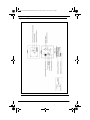
93507621000 WM10002000UserManual.book Page i Monday, April 27, 2009 3:09 PM
Model WM1000/WM2000
Wall Mount Intercom Stations
User Instructions
9350-7621-000 Rev G
04/2009
93507621000 WM10002000UserManual.book Page ii Monday, April 27, 2009 3:09 PM
Proprietary Notice
Shipping to the Manufacturer
The product information and design
disclosed herein were originative by and are
the property of Bosch Security Systems, Inc.
Bosch reserves all patent, proprietary design,
manufacturing, reproduction, use and sales
rights thereto, and to any article disclosed
therein, except to the extent rights are
expressly granted to others.
All shipments of product should be made via
UPS Ground, prepaid (you may request from
Factory Service a different shipment
method). Any shipment upgrades will be
paid by the customer. The equipment should
be shipped in the original packing carton. If
the original carton is not available, use any
suitable container that is rigid and adequate
sized. If a substitute container is used, the
equipment should be wrapped in paper and
surrounded with at least four)(4) inches of
excelsior or similar shock-absorbing
material. All shipments must be sent to the
following address and must include the
Proof of Purchase for warranty repair.Upon
completion of any repair the equipment will
be returned via United Parcel Service or
specified shipper, collect.
Copyright Notice
Copyright 2009 by Bosch Security Systems,
Inc. All rights reserved. Reproduction, in
whole or in part, without prior written
permission from Bosch is prohibited.
Warranty Notice
See the enclosed warranty card for further
details.
Customer Support
Technical questions should be directed to:
Customer Service Department
Bosch Security Systems, Inc.
12000 Portland Avenue South
Burnsville, MN 55337 U.S.A.
Telephone: 1-800-392-3497
Fax: 1-800-323-0498
Factory Service: 1-800-553-5992
Return Shipping Instructions
Customer Service Department
Bosch Security Systems, Inc. (Lincoln, NE)
Telephone 1-402-467-5321
Fax: 1-402-467-3279
Factory Service: 1-800-553-5992
Please include a note in the box which
supplies the company name, address, phone
number, a person to contact regarding the
repair, the type and quantity of equipment, a
description of the problem and the serial
number(s).
Factory Service Department
Bosch Security Systems, Inc.
8601 East Cornhusker Hwy.
Lincoln, NE 68507 U.S.A.
Attn: Service
FCC Statement
This equipment uses, and can radiate radio
frequency energy that may cause
interference to radio communication if not
installed in accordance with this manual. The
equipment has been tested and found to
comply with the limits of a Class A
computing device pursuant to Subpart J, Part
15 of FCC Rules which are designed to
provide reasonable protection against such
interference when operated in a commercial
environment. Operation of this equipment in
a residential area may cause interference
which the user (at his own expense) will be
required to correct.
This product meets Electromagnetic Compatibility Directive 89/
336/EEC
93507621000 WM10002000UserManual.book Page 1 Monday, April 27, 2009 3:09 PM
Table
Of
Contents
WM1000/WM2000 ...............................................................................1
Introduction ...........................................................................................1
Description ............................................................................................1
Reference View .....................................................................................2
Features .................................................................................................3
Installation ............................................................................................6
Configuration Switch Pre-check ...........................................................6
Mic Kill DIP Switch (DIP Switch 1) ....................................................6
DC Call Enable (DIP Switch 2) ............................................................6
Incoming Call Beep (DIP Switch 3) .....................................................6
Headset Microphone Type Selection (DIP Switch 4) ...........................7
Balanced/Unbalance Switch (SW-1) ....................................................7
Intercom Channel Connections .............................................................8
General Information ..............................................................................8
Method 1: Phantom Powered Connection ............................................8
Method 2: Locally Powered Connection ..............................................8
All Locally Powered Intercom Stations (Dry Lines) ............................9
Dynamic-Mic Headset Connection .......................................................9
Power Up ............................................................................................10
Sidetone Adjustment ...........................................................................10
Operation ............................................................................................17
Channel Select (WM2000 Only) ........................................................17
Receiving Calls ...................................................................................17
Calling an Intercom Channel ..............................................................17
Unbalanced Mode ...............................................................................18
Specifications ......................................................................................19
93507621000 WM10002000UserManual.book Page 2 Monday, April 27, 2009 3:09 PM
93507621000 WM10002000UserManual.book Page 1 Monday, April 27, 2009 3:09 PM
CHAPTER 1
WM1000/WM2000
Introduction
Thank you for purchasing the Audiocom WM1000/2000 Wall Mount Intercom
Station. We hope the many design features of this product will satisfy your
intercommunication requirements for many years to come. To get the most out of
your new intercom station, take a few moments to look through this booklet before
using the Intercom Station for the first time.
Description
The WM1000/2000 Intercom Stations are designed for stationary, wall-mounted
installation in standard two-gang electrical boxes. The WM1000 is a single-channel
station. The WM2000 provides switch-selectable access to either of two (2) intercom
channels. The WM1000 and WM2000 are ideal when users need access to the
intercom station from strategic locations where a desktop station would not be
suitable or they do not wish to carry around a belt-pack station. Since all of the
intercom electronics are in the intercom station, the user need only to connect a
headset or telephone style handset to begin communicating. Alternatively, a headset
or telephone handset can be attached and left at the wall unit.
1
93507621000 WM10002000UserManual.book Page 2 Monday, April 27, 2009 3:09 PM
Reference View
FIGURE 1.
Reference View, WM-2000 shown.
2
93507621000 WM10002000UserManual.book Page 3 Monday, April 27, 2009 3:09 PM
Features
NOTE:
The numbered features list in
Channel Select Switch (WM-2000 Only) The channel select switch is used to switch between
intercom channels one and two. The switch lights green
for channel one and red for channel two.
Intercom Listen Key The intercom listen key can be used in both momentary
(push-to-listen) and latching (hands-free listen) modes.
Momentary Mode Press and hold the TALK button, then
speak into the microphone. The green
talk LED remains lit while the TALK
button is held. Release the TALK button
when finished talking. The talk LED
will turn off.
Latching Mode for Hands-free Conversation Tap the TALK button (do not press and
hold). The green talk LED turn on and
remains on. When finished talking, tap
the TALK button again. The talk LED
turns off.
Call Key:
The Call key is used to send call signals on the intercom
channel and to indicate incoming calls.
3
93507621000 WM10002000UserManual.book Page 4 Monday, April 27, 2009 3:09 PM
Intercom Talk Key:
The talk key can be used in both momentary
PTT (push-to-talk) and latching (hands-free talk) mode.
Momentary Mode Press and hold the TALK button, then
speak into the microphone. The green
talk LED remains lit while the TALK
button is held. Release the TALK button
when finished talking. The talk LED
will turn off.
Latching Mode for Hands-free Conversation Tap the TALK button (do not press and
hold). The green talk LED turn on and
remains on. When finished talking, tap
the TALK button again. The talk LED
turns off.
Dynamic-Mic Headset Connector The dynamic-mic headset connector is a 4-pin male XLR
connector. It accepts headsets with monaural headphones
and either a balanced or unbalanced dynamic microphone.
Volume Control The volume control adjusts intercom volume to
headphones.
Audiocom/Clear-Com Selector Switch The selector switch sets the intercom station for
compatibility with either Audiocom or Clear-Com channel
connector pin-outs, channel power requirements, and call
signaling requirements.
Configuration DIP Switches The DIP Switches are provided to enable/disable the
following features:
Mic Kill With this feature activated, the station’s
microphone may be turned off from a
remote master controller.
4
93507621000 WM10002000UserManual.book Page 5 Monday, April 27, 2009 3:09 PM
Call Beep An optional call beep tone can be used
for incoming call notification.
Headset Mic Selection Balanced or unbalanced microphone
may be selected.
DC Call Enable: This may be turned on to use the
intercom station with intercom systems
that use DC call signaling.
Connections Terminal Block The terminal block is used to connect intercom channel(s)
and an optional local power supply.
Sidetone Trimmers The sidetone trimmers are used to adjust the level of the
station operator’s own voice in the headphones.
Mounting Holes The mounting holes fit any standard, two-gang electrical
box.
5
93507621000 WM10002000UserManual.book Page 6 Monday, April 27, 2009 3:09 PM
Installation
Configuration Switch Pre-check
Before making connections, read the configuration switch notes that follow and make
sure all switches are properly set for your intended usage. Chapter 1, “Configuration
Switch Settings,” on page 7 lists the switch descriptions and factory default settings.
The location of the DIP switches are shown in Figure 1 on page 2.
Mic Kill DIP Switch (DIP Switch 1)
Audiocom master stations can transmit an inaudible signal to turn off the microphones
in all remote intercom stations (including WM1000/2000) on an intercom channel.
This is useful when a remote intercom station has been left unattended with the
microphone on. However, you may wish to disable the mic kill feature at the
WM1000/2000, if communications are critical in nature where it is absolutely
essential the microphone never be remotely disabled.
DC Call Enable (DIP Switch 2)
Leave this switch in the open position for Audiocom applications. Set it to the closed
position if the WM1000/2000 will be used in a Clear-Com intercom system.
Incoming Call Beep (DIP Switch 3)
By default, incoming calls are indicated by a red-flashing Call key and a beep tone in
the headphones. If you do not want the beep tone, set DIP switch 3 to the closed
position.
6
93507621000 WM10002000UserManual.book Page 7 Monday, April 27, 2009 3:09 PM
TABLE 1. Configuration
SWITCH
NUMBER
Switch Settings
DESCRIPTION
SETTINGS
OPEN=OFF, CLOSED =ON
DEFAULT
SETTINGS
1
Mic Kill Receive
Closed: Disabled, No Mic Kill
Open: Enabled, Mic Kill Active
Open
2
Call Signal Method
Closed: DC (SW1 set to UNBAL)
Open: Audiocom (SW1 set to BAL)
Open
3
Incoming Call Beep
Closed: Disabled
Open: Enabled
Open
4
Microphone Type
Closed: Unbalanced
Open: Balanced
Open
5
Speaker Beep for
Incoming Call
Closed: Enabled (DIP switch 3 must
be set to open)
Open: Disabled
Open
6
Not Used
Not Defined
Open
7
Not Used
Not Defined
Open
8
Not Used
Not Defined
Open
Headset Microphone Type Selection (DIP Switch 4)
If the headset specifications indicate the microphone type is balanced, or if you are
unsure, leave this switch in the off (default) position. If the specifications indicate an
unbalanced microphone, set DIP switch to on.
Balanced/Unbalance Switch (SW-1)
This switch is set at the factory to the balanced (BAL) position for use with
Audiocom intercom channels. Set the switch to the unbalanced (UNBAL) position for
use with Clear-Com intercom systems. Be sure and use the appropriate connection
information based on how you have this switch set.
7
93507621000 WM10002000UserManual.book Page 8 Monday, April 27, 2009 3:09 PM
Intercom Channel Connections
IMPORTANT:
The following paragraphs and illustrations describe installation
of the WM1000/2000 in and Audiocom Intercom System.
General Information
The WM1000/2000 mounts in a standard two-gang electrical box. Some example
intercom system configurations are shown in Figure 2 through Figure 5. Detailed
connections for the WM1000/2000 are shown in Figures 6 and 7. There are two (2)
basic methods for connecting the WM1000/2000:
•
•
NOTE:
use phantom powered connection
use local power
After connecting intercom stations as described below, and before
installing the mounting screws, connect a headset and perform the
sidetone adjustment as described on page 10.
Method 1: Phantom Powered Connection
In this method, operating power and intercom audio are delivered to the
WM1000/2000 over the same wires. The advantage of this setup is simplicity of
connection. Also, the Audiocom power supply automatically provides terminating
impedance for the intercom system. Without this terminating impedance, the sound
quality on the channel is distorted, and the levels shift each time additional stations
are connected to the channel. The disadvantage of the phantom power method is that
some operating power is lost over very long intercom cables, and performance is then
reduced at remotely located stations. Generally, if the intercom stations are located
within a few hundred feet of the power supply, the phantom power is sufficient. The
actual distance over which power is delivered can vary, however, depending on the
number of stations connected. Increasing the number of stations reduces the distance.
NOTE:
The range over which power can be delivered is independent from the
range over which audio can be sent. Audio can be transmitted for several
miles, providing that intercom stations are locally powered, see “Method
2: Locally Powered Connection.
Method 2: Locally Powered Connection
Using this method, the intercom station is connected to the intercom line just like any
phantom-powered intercom station, except that a local power supply is also
connected. This local power supply is located with the intercom station and provides
power for that station only. Since power loss on the intercom lines is no longer an
8
93507621000 WM10002000UserManual.book Page 9 Monday, April 27, 2009 3:09 PM
issue, the operating range is now limited only by the audio transmission range, which
is several miles. Another advantage to this method is more stations can be connected
to the intercom channels. When local power is supplied to an intercom station, the
station detects this and automatically disconnects from the phantom power supply. As
long as an Audiocom power supply is located somewhere in the intercom system, the
proper terminating impedance is supplied to all stations.
All Locally Powered Intercom Stations (Dry Lines)
If all intercom stations are widely distributed, you can dispense with a main power
supply and use local power for each station. When no power is delivered on the
intercom channels, this is known as dry-line operation. However, since an Audiocom
power supply is not used, a line termination must be inserted in each intercom
channel for proper operation. An example of dry line operation is shown in Figure 5
on page 14. The required termination components are shown in Figure 8 on page 16.
Dynamic-Mic Headset Connection
NOTE:
For headset specifications, see page 19. For best results in noisy
environments, a noise cancelling (directional or cardioid) microphone is
highly recommended.
To use the dynamic-mic headset, do the following:
1.
Verify DIP Switch 4 is properly set for balanced or unbalanced
microphone. See Chapter 1, “Configuration Switch Settings,” on page 7.
2.
Plug the headset into the headset connector on the unit.
3.
Power up the intercom system.
4.
Check the sidetone adjustment before placing the station in operation.
9
93507621000 WM10002000UserManual.book Page 10 Monday, April 27, 2009 3:09 PM
Power Up
Make sure any local power supplies are plugged in, and turn ON the power switches
of any phantom power supplies.
NOTE:
If you are using a large number of locally powered intercom stations (10
or more), you should activate their local power supplies before
activating any phantom power supply. Otherwise, you may get an
overload indication on the phantom supply. In this case, either reset the
phantom supply, or momentarily turn it OFF, then ON.
Sidetone Adjustment
The WM1000/2000 uses full-duplex audio (the same as conventional telephone lines)
in which the talk and listen audio are sent and received on the same wires. When you
talk on a channel, you also hear your own voice back in the headphones. If you are
using open-ear style headphones, this could cause unwanted feedback, since the
microphone may pick up your returned voice audio and re-amplify it.
On the other hand, if you are using headphones that completely enclose the ears, a
certain amount of your own voice level is desirable to overcome the muffled sensation
when talking. The sidetone adjustment is different for these two situations.
To adjust the sidetone, do the following:
1.
Activate channel 1.
NOTE: Required only for the WM2000, the WM1000 is active on
whichever channel it is connected to).
2.
Activate talk and listen.
3.
Slowly increase the volume to maximum while talking into the microphone.
4.
Using a small, flathead screwdriver, adjust the channel 1 sidetone trimmer
(Figure 1 on page 2) to minimize you voice level in the headphones
5.
For the WM2000 only, activate channel 2 and repeat 2 through 4 to adjust
channel 2 sidetone.
6.
Install the intercom station mounting screws after completing the
adjustments.
The station is now ready for use.
10
93507621000 WM10002000UserManual.book Page 11 Monday, April 27, 2009 3:09 PM
.
FIGURE 2. PS2001L Power Supply set to isolate mode
Figure 2 shows a 2-channel intercom system using a PS2001L Power Supply set to
isolate mode. In isolate mode, each intercom channel is a separate party line, and total
current for each channel is limited to 1 amp. Note, both WM1000 and WM2000
stations may be connected, depending on each locations need to communicate with
one or two channels. WM1000 stations may be connected to either channel one or
two. Also note, locally powered stations may be connected. This is recommended
when stations are installed at remote locations. Since the PS2001L provides
termination for the intercom channels, no user-installed termination is required. For
WM1000 connection details, refer to Figure 6, for WM2000, refer to Figure 7.
11
93507621000 WM10002000UserManual.book Page 12 Monday, April 27, 2009 3:09 PM
FIGURE 3. A single-channel intercom system using one PS2001L with WM1000
Intercom Stations.
Figure 3 shows a single-channel intercom system using one PS2001L with WM1000
Intercom Stations. The PS2001L may be set to either combine or isolate mode. In
combine mode, all intercom stations talk on a single party line, and total current for
the channel is 2 amps. In isolate mode, one string of intercom stations is operated as
channel one, and the other string is operated at channel two. There is no
communication between the separate channels, and the total current per channel is 1
amp. For WM1000 connection details, refer to Figure 6.
12
93507621000 WM10002000UserManual.book Page 13 Monday, April 27, 2009 3:09 PM
FIGURE 4. A two-channel intercom system using two PS2001L power supplies.
Each PS2001L is set to combine mode and it supplies power to one intercom channel
only. Each intercom channel is a separate party line, and total current for each channel
is limited to 2 amps. Note, both WM1000 and WM2000 Intercom Stations may be
connected, depending on each locations need to communicate with one or two
intercom channels. For WM1000 connection details, refer to Figure 6, for the
WM2000 refer to Figure 7.
13
93507621000 WM10002000UserManual.book Page 14 Monday, April 27, 2009 3:09 PM
FIGURE 5. Locally powered intercom system
An example of an intercom system using all local powered stations, with no power
being distributed on the intercom channels (dry lines). WM2000 stations are shown,
but WM1000 stations by also be used. Since an Audiocom power is not used, the
install must connect a line termination somewhere in each channel for proper
operation. The required line termination is shown in FIgure 8.
14
93507621000 WM10002000UserManual.book Page 15 Monday, April 27, 2009 3:09 PM
FIGURE 6. Audiocom mode connections for WM1000 Intercom Station.
15
93507621000 WM10002000UserManual.book Page 16 Monday, April 27, 2009 3:09 PM
FIGURE 7. Audiocom mode connections for a WM2000 Intercom Station
FIGURE 8. Audiocom mode line termination for dry line operation (one required for
each channel).
16
93507621000 WM10002000UserManual.book Page 17 Monday, April 27, 2009 3:09 PM
Operation
Channel Select (WM2000 Only)
To change the WM2000 channel, do the following:
>
Tap the Ch Select key to select channel 1 or 2.
The key is green when channel 1 is selected and red when channel two is
selected.
Receiving Calls
When there in an incoming call signal the Call key flashes red. There is also a beep
tone in the headphones if the beep feature in activated, see “Incoming Call Beep (DIP
Switch 3)” on page 6.
Incoming call indication is provided only for the currently selected channel on the
WM2000 unit only.
To receive calls, do the following:
1.
NOTE:
Turn on the talk and listen keys to begin your conversation.
You can turn the talk and listen keys on in either momentary or latched
mode. For latched operation, tap the key to turn it on. Then, tap it again
to turn it off, when finished.
Calling an Intercom Channel
To make a call, do the following:
1.
Select the desired intercom channel (WM2000 only).
2.
Press and hold the call key.
An inaudible call signal will be sent, and the Listen key automatically turns
on.
3.
Release the call key and activate the talk key when a call is received.
4.
Turn off talk and listen keys to end the conversation.
17
93507621000 WM10002000UserManual.book Page 18 Monday, April 27, 2009 3:09 PM
Unbalanced Mode
To use the WM1000/2000 in a Clear-Com Intercom System, do the following
1.
Set SW1 to the UNBAL position.
2.
Set DIP switch 2 to the Closed position.
3.
Connect the Clear-Com channel wires using the Unbalanced Mode
Intercom Channel pin-out information listed in the “Specifications” on
page 19.
93507621000 WM10002000UserManual.book Page 19 Monday, April 27, 2009 3:09 PM
Pin 4 Intercom channel 1 audio high +24VDC
phantom power
Specifications
Pin 5 Intercom channel 2 audio low +24VDC
phantom power
General
Power Requirements
Pin 6 Intercom channel 2 audio high +24VDC
phantom power
Phantom Power: 24VDC nominal (30VDC),
150mA
Intercom Channel, Unbalanced Mode (SW-1 set to
UNBAL position)
Local Power: 15VDC, 150mA
Output Level
Dimensions:
0.707VRMS ±10%
Mounts in a standard 2-gang electrical box
Input Impedance
Environmental Requirements
Storage: -20°C to 80°C; 0% to 95% humidity,
non-condensing
Operating: -15°C to 60°C; 0% to 95% humidity,
non-condensing
Dynamic-Mic Headset
200 Ohms
Bridging Impedance
greater than 5,000 Ohms
Sidetone
-40dB, 35dB adjustable range
Microphone:
Call Signaling
150 to 500 Ohm, dynamic (balanced or
unbalanced)
Send 11 ±3VDC
Receive 4VDC minimum
Headphones
Connector Type - Six-position terminal block with
screw-in wire clamps
150 to 600 Ohm, monaural
Connector Type: XLR-4M
Pin 1 Common
Pin 1 - Microphone Low
Pin 2 Local power (15VDC, 150mA)
Pin 2 - Microphone High
Pin 3 Channel 1 24–30VDC input
Pin 3 - Headphone High
Pin 4 Channel 1 intercom audio high and DC
call
Pin 4 - Headphone Low
Intercom Channels Balanced Mode (SW1 set to BAL
position)
Output Level:
1Vrms nominal
Input Impedance:
300 Ohms
Bridging Impedance:
greater than 5,000 Ohms
Sidetone:
35dB adjustable range
Call Signaling:
Send: 20kHz ±100Hz, 0.5Vrms ±10%
Receive: 20kHz ±800Hz, 100mVrms ±10%
Mic-Kill Detect Frequency:
24kHz ±800Hz, 100mVrms
Noise Contribution:
less than -70dB
Common Mode Rejection Ratio:
greater than 50dB
Connector Type: Six-position terminal block with
screw-wire clamps
Pin 1 Audio and DC Common
Pin 2 Local power (15VDC, 150mA)
Pin 3 Intercom channel 1 audio low +24VDC
phantom power
19
Pin 5 Channel 2 24–30VDC input
Pin 6 Channel 2 intercom audio high and DC
call
93507621000 WM10002000UserManual.book Page 20 Monday, April 27, 2009 3:09 PM