1
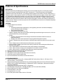
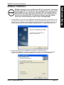
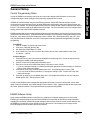
Remote Management Software
PC & ELK TS07 Touchscreen Edition
05/07
PO Box 100
3266 US Hwy 70 West
Hildebran, NC 28637
828-397-4200 Voice
www.elkproducts.com 828-397-4415 Fax
ElkRM Product Instruction Manual
Contents
Features & Specifications .............................................. 1-1
Software Installation ....................................................... 1-2
General Setup .................................................................. 1-4
Control Programming Notes ...................................................................
ElkRM Software Setup ............................................................................
Page Setup .............................................................................................
COMM SETUP ........................................................................................
Product License Key (for PC or Pocket PC Installations) ......................
Display Settings (for Touchscreen Installations) .....................................
1-4
1-4
1-5
1-6
1-8
1-9
Advanced Setup .............................................................. 1-9
Changing Program Sounds ..................................................................... 1-9
Skins ...................................................................................................... 1-10
ElkRM Setup Utility ......................................................... 2-1
ElkRM Setup Utility Layout ...................................................................... 2-1
The Toolbar ............................................................................................. 2-2
Video Setup ............................................................................ 2-2
Network Connection Setup .................................................................
Adding Folders ...................................................................................
Adding Cameras .................................................................................
Custom Item Setup ............................................................................
Moving Items ......................................................................................
Deleting Items ....................................................................................
Sending Video Setup to ElkRM ..........................................................
2-2
2-3
2-4
2-4
2-5
2-5
2-6
ElkRM Product Instruction Manual
Audio Setup ............................................................................ 2-6
Network Connection Setup .................................................................
COMM Settings ..................................................................................
Source Setup ......................................................................................
Controller Setup ..................................................................................
Sending Audio Settings to ElkRM.......................................................
2-6
2-6
2-7
2-8
2-8
Links Setup ............................................................................ 2-9
Network Connection Setup ................................................................. 2-9
Adding Folders ................................................................................... 2-9
Adding Links ..................................................................................... 2-10
Moving Items .................................................................................... 2-10
Deleting Items .................................................................................. 2-10
Sending Links to ElkRM.................................................................... 2-10
Operating Instructions.................................................... 3-1
Basic Operation ....................................................................................... 3-1
Security.................................................................................................... 3-1
Switching to Other Keypads .................................................................... 3-4
Lighting .................................................................................................... 3-5
Climate .................................................................................................... 3-7
Tasks ....................................................................................................... 3-8
Outputs .................................................................................................... 3-9
Custom Settings .................................................................................... 3-10
Links .......................................................................................................3-11
Video ......................................................................................................3-11
Audio ..................................................................................................... 3-13
Cleaning the Screen (For touch sensing screens only) ....................... .3-20
Software Setup
ElkRM Product Instruction Manual
Features & Specifications
APPLICATION:
ElkRM PC Edition Remote Management software runs as an executable program on virtually any personal
computer or Pocket PC running the Microsoft .NET Framework 2.0. This same software is also available
preloaded on Elk’s TS07 Touchscreen. It provides a powerful graphic user interface to an M1 or EZ8 system. It
allows the control of many aspects of the M1 or EZ8 system including security, lighting, climate, tasks, outputs,
etc. ElkRM Remote Management software can connect to the control through an Ethernet network or direct
through the control’s main serial port (serial connection should not exceed 50 ft.). Multiple connections can be
established through the Ethernet network, while connection through the control’s main serial port allows only a
single connection. Ethernet connectivity requires the ELK-M1XEP Ethernet Interface to be installed and properly
configured on the system.
FEATURES:
! Powerful Graphic User Interface:
" Security:
# Virtual Keypad allows arming/disarming, zone bypassing and chime activation and displays
system arm/alarm/trouble messages
# View Individual Zone Status
# Receive and View System Event Log
" Lighting: Displays name and current status of defined lights and allows light to be turned on, off or set
to intermediate level (on dimmable lights)
" Climate:
# Displays current temperature and settings of interfaced thermostats and allows control of
thermostat settings
# Displays name and current temperature of any keypad and temperature probes
" Outputs: Displays name and current status of defined outputs and allows output to be turned on and
off.
" Tasks: Displays name of defined tasks and allow task to be activated
" Custom Settings: Displays name and current setting of defined custom settings and allows those
settings to be changed
" Links: Allows addition of URL shortcuts, which can be viewed in a web browser.
" Video: Allows access to imagery from compatible IP accessible cameras and DVRs
" Audio: Allows control of compatible audio distribution system components
! Easily Customizable to show/hide GUI items listed above
! Appearance of GUI is fully customizable
! Self Update Function (requires high speed Internet connection)
! Synchronize option simplifies page setup
! Up to 30 simultaneous connections over the local network
SYSTEM REQUIREMENTS:
! Supported Operating Systems (PC): Windows 98SE, ME, 2000 (Service Pack 3) , XP Home & Pro
(Service Pack 2) , or Server 2003
! Supported Operating Systems (Mobile Devices): Windows Mobile Software for Pocket PC 2003, Windows
Mobile 5.0 for PocketPC and Smartphone, or Windows CE .NET 5.0 and higher. (Microsoft ActiveSync
required for installation)
! Computing Device running Microsoft .NET 2.0 Framework
! Total Disk Space Requirements: 285 MB (280 MB for .NET 2.0 and 5 MB for ElkRM)
! Memory Requirements: Minimum 64 MB RAM
! Screen Resolution: 640 x 480
! Internet Explorer 5.01 or later
! M1 or EZ8 system with firmware version 4.3.8 or later
Page 1- 1
Section 1 - ElkRM Software Setup
ElkRM Product Instruction Manual
ElkRM is designed to run in the Microsoft .NET 2.0 environment. This means
that Microsoft .NET 2.0 Framework must be installed on the computing device
before ElkRM can run on the device. Microsoft .NET 2.0 Framework can be
downloaded at no charge from www.microsoft.com. If the computing device
does not have Microsoft .NET 2.0 Framework installed, go to the website
listed above and download and install it before installing ElkRM.
1. To install ElkRM, you must first obtain a CDROM or download the software from www.elkproducts.com.
If installing from a CDROM, select Install ElkRM to start the ElkRM InstallShield Wizard or it may run
automatically. If the software is downloaded from the website locate the executable setup file on your
computer and double click it to run the ElkRM InstallShield Wizard. To begin installing click next.
2. Next, select the location where ElkRM is to be installed. The default option is
C:\\Program Files\ElkRM. To install the software here, click Next. To install ElkRM in a different
location, click the Browse button and select another folder and click OK. Then click Next.
Section 1 - ElkRM Software Setup
Page 1- 2
Software Setup
Software Installation
Software Setup
ElkRM Product Instruction Manual
3. Next, select which version of ElkRM to install. If ElkRM is being installed on a desktop or laptop
PC only, select “ElkRM for Desktop/Laptop PCs” only. If ElkRM will be installed on a mobile
device such as a Pocket PC, then select “ElkRM for Mobile (Windows CE) Devices”. If ElkRM
will be installed on a PC and a mobile device, then select both PC and Mobile Device options. The
ElkRM Setup Utility may also be installed by selecting “RM_Setup Utility for Desktop/Laptop PCs”.
Once the desired options have been selected click Next. The software will then be installed.
4. When the software installation is complete, click the Finish button.
Page 1- 3
Section 1 - ElkRM Software Setup
ElkRM Product Instruction Manual
Control Programming Notes
In order for ElkRM to successfully connect to the control and to display valid information on the remote
management pages, certain settings must be properly programmed in the control.
If ElkRM will connect with the control over an Ethernet network, the M1XEP Ethernet Interface must be
connected to the main serial port (Port 0) of the M1/EZ8 control and properly configured. Ensure that the nonsecure port is enabled. It is recommended that the M1XEP be configured with a static IP address if the network
permits. This will ensure that the IP address does not change. For more information on how to configure these
setting, please refer to the M1XEP Installation manual.
ElkRM generates the remote management pages based on the serial data it receives from the main serial port
(Port 0) of the M1/EZ8 control. To ensure that all the necessary serial information is being transmitted from the
serial port, verify that the Serial Port 0 baud rate is set to 115200. Also, Global options G35, G36, G37, G38,
G39, and G40 must be enabled or set to YES. These options can be programmed through ElkRP or keypad
programming.
From ElkRP
1. Click on “Globals” on the left side of the screen.
2. Click on the “G29-G42 (Special)” tab.
3. Set “Serial Port 0 Baud Rate” to 115200
4. In the “Serial Port 0” box in the center of this screen, place a check mark beside of each of the
6 “Transmit...” options.
From the Keypad
1. Press the ELK key, then 9 to access the Installation Programming menu. Press the right arrow key
and enter the installer code when prompted.
2. Press 07 to enter the Global System Definitions menu
3. Enter 34 to view the current baud rate setting. Verify that it is set to 115200
• If it is not, change the setting to 115200 by pressing the right arrow and then pressing 9. Press the
ELK key after making the change.
4. Press the Up arrow key to view the Global option G35. Verify that this option is set to YES.
• If it is not, press the Elk key and then 1 to change the setting to YES. Press the ELK key after
making the change.
5. Press the up arrow key to view Global option G36. Use the process outlined in step 4 to verify that
Global options G35 - G40 are all set to YES.
In order for the ElkRM screens to display the appropriate information, items such as keypads, zones, tasks,
lights, outputs, thermostats, and custom settings must be named. Tasks, Lights and Outputs also require that
the “Show” option be enabled. These options must be programmed using ElkRP.
ElkRM Software Setup
Upon starting the ElkRM software for the first time, a dialog box will appear stating you must click on the
ElkRM logo to setup the program options. Before ElkRM can connect with an M1 control, setup information
regarding the connection methods and page settings must be entered. Click OK on this screen and then click
the ElkRM logo located in the upper left hand corner of the screen. This will take you to the setup screen,
where the page and communication options are selected.
Section 1 - ElkRM Software Setup
Page 1- 4
Software Setup
General Setup
Software Setup
ElkRM Product Instruction Manual
Page Setup
The OPTIONS page provides configuration selections that will affect the information displayed on the
remote management screens.
Keypad Name: Once a connection is established, this drop down box will be populated with
the names of all the keypads the user has privileges to see. This drop down box is not
used for the initial setup.
Enable Audible Key Presses: Enabling this option produces an audible tone with each key press.
Show Extended Lighting Controls: This option should only be enabled if the M1 or EZ8 is interfaced
with lighting equipment that adheres to the X-10 format of powerline lighting. It provides extended lighting
commands such as Dim, Bright, All Lights On, All Lights Off, and All Units Off.
Use Large Keyboard (Touchscreen): Ordinarily the PC’s full size keyboard will be used for entering text
data or numbers when required. However, if ElkRM is installed on a PDA or touchscreen this option
enables a large keyboard to appear on the screen when entering setup information.
Show Security/Lighting/Climate/Tasks/Outputs/Custom/Links/Video/Audio: These options affect
which pages will be displayed. Place a check mark beside of each category to be displayed. If a
particular category will not be used, remove the check mark from beside of it. The corresponding button
on the left side of the screen will not be displayed.
Clean Screen: If ElkRM is installed on a touchscreen, clicking this button will provide a blank
screen for 30 seconds, allowing the user to clean the screen.
Close Program: Click this button to close the program.
Page 1- 5
Section 1 - ElkRM Software Setup
ElkRM Product Instruction Manual
After selecting the desired choices on the OPTIONS page, click on the COMM SETUP button to set up the
communications options. The ElkRM software allows two methods of connection to the M1/EZ8 Control:
Network and Serial. The network connection method requires the installation of the M1XEP Ethernet Interface.
The serial connection method requires a physical connection to the main serial port on the control. The
M1Gold has the main serial port on-board while the M1EZ8 requires the M1EZ8MSI Main Serial Interface to
provide this connection.
The drop down box at the top of this page allows the selection of the default connection method. Three
options are available: Network, Serial, and Select When Program Starts. If “Select When Program Starts”
is chosen, the program will allow the user to choose between the configured connection options upon
start up.
Ethernet Setup
IP Address: Enter the URL or IP address of the M1XEP Ethernet Interface. It is
recommended that the ELK-M1XEP be configured with a static IP address to
prevent the address from changing. For information on configuring the M1XEP with a static IP
address, please refer to the M1XEP Installation Manual.
Port Number: Enter the non-secure port number configured in the M1XEP. Verify in ElkRP that
the non-secure port has been enabled. For information on enabling the non-secure port, please
refer to the M1XEP Installation Manual. The default port number for the M1XEP and ElkRM is
2101.
Serial Port Settings
To configure ElkRM to connect from the PC’s serial port to the M1 or EZ8 the main serial port, choose
the PC’s “COM” or port ID number (COM1, COM 2, etc.) from the drop down box. Make certain to
select the COM port that is physically connected to the main serial port (port 0) on the M1/EZ8.
IMPORTANT: ElkRM does not currently support SSL (encrypted) secure connections. As
such, ElkRM cannot be used outside the local network without opening (port forwarding)
the non-secure, unencrypted port. Connecting to ElkRM outside the local network using
the non-secure port is STRONGLY DISCOURAGED, due to the obvious security issue this
presents.
Section 1 - ElkRM Software Setup
Page 1- 6
Software Setup
COMM SETUP
Software Setup
ElkRM Product Instruction Manual
Enabling the “Automatically try to reconnect” option allows the software to try to reconnect if it loses
connection with the control. The software will try to reconnect every minute if the connection is lost.
The “Always use this code to logon” option is convenient if the user does not wish to enter a usercode
each time ElkRM connects to the control. This option is required if the “Automatically try to reconnect”
option is enabled. To enable this option, enter a valid user code in the field. For each digit entered an
asterisk (*) will be inserted in the text box, preventing the user code from being viewed.
Saving Settings
If ElkRM detects that new connection settings have been entered on the COMM SETUP page, the SAVE
button will become red, prompting the installer to save the settings. Click the SAVE button to save the
settings. The button will change from red to gray indicating the changes have been saved.
!
If the “Use Large Keyboard” option is selected, the SAVE will not turn red because it
saves this setting automatically. Also, the SAVE button will not turn red if a checkbox
setting is changed. ElkRM saves these settings automatically as well.
Connecting and Synchronizing
After entering the appropriate connection information and saving the settings, click on the CONNECT
button to establish a connection with the control. If prompted, enter a valid user code and press the ENTER
button. If the connection request is successful, the SYNCHRONIZE button will become enabled. Click the
SYNCHRONIZE button.
The SYNCHRONIZE button is used to automatically generate the remote management pages, eliminating
the need for the installer to manually set up the pages. When the SYNCHRONIZE button is clicked, ElkRM
polls the control for all the data required to generate the pages. The pages are then automatically built from
this data.
!
A synchronize is recommended ANYTIME new options (zones, lighting, outputs, tasks, etc.)
are programmed into the control panel.
Updating the Software
This option is only functional if/when the computing device is connected to a network with high speed
Internet access. Pressing UPDATE instructs ElkRM to go over the internet and access a special website
containing the latest update for the for the program. It then downloads and installs the update
automatically.
Page 1- 7
Section 1 - ElkRM Software Setup
ElkRM Product Instruction Manual
ElkRM will connect and synchronize with a control without a product license key, but will only provide limited
functionality. Basically, a product license key is required for each M1/EZ8 control that it needs to connect to. If
ElkRM connects to a control without the product key, the logo in the upper left hand corner will display “DEMO”
as shown below.
A Product License Key may be purchased through an Authorized Elk Reseller. The serial number from the
M1/EZ8 control is required to obtain the product key license.
To add a product license key, click on the Product Keys button. The upper window displays any product keys
that have already been added to ElkRM. After the product license key has been purchased, enter the key in the
field labeled “Type your product key here”. Click the ADD KEY button and the key will appear in the upper
window. If the key entered is valid, the DEMO indication will be removed from the logo.
A product license key can be removed from ElkRM by highlighting the key in the upper window and clicking the
DELETE KEY button.
Exiting Setup: Select any of the buttons on the left side of the screen to exit setup and return to the User
operating screens.
Limitations in DEMO Mode
Security Screen- Allows arming and disarming with code only. The event log can be viewed. The Status page
will only display the first zone programmed in the system. The quick arm buttons, bypass button, chime button
and function buttons do not work in DEMO mode.
Climate- The climate screen is not functional in DEMO mode. The Thermostat page displays invalid data, and
will not control any thermostat connected to the system. The sensors page will display valid names for keypad
and sensors but does not display the actual temperature at that sensor.
Lighting/Tasks/Outputs/Custom/Links/Video/Audio- These pages will display only 1 item. This is the first item
programmed in the system for that category.
Section 1 - ElkRM Software Setup
Page 1- 8
Software Setup
Product License Key (for PC or Pocket PC Installations)
This screen does not appear on the Elk TS07 Touchscreen, as entering a product license key is not required.
ElkRM Product Instruction Manual
Software Setup
Display Settings (for Touchscreen Installations)
The SETTINGS page provides display settings for the Elk TS07 touchscreen that affect the backlight and
volume levels.
Backlight Maximum Intensity: This drop down box allows the adjustment of the maximum or active
backlight intensity level. This level can be adjusted from 10 percent to 100 percent in increments of 10
percent.
Go To Minimum Intensity in: If there is no activity on the touchscreen for the length of time selected in
this drop down box, the backlight will be adjusted to the minimum intensity level. If NEVER is selected, the
backlight will always remain at the maximum intensity level.
Backlight Minimum Intensity: This drop down box allows the adjustment of the minimum or inactive
backlight intensity level. This level can be adjusted from 0 percent (or OFF) to 90 percent in increments of
10 percent.
Volume Level: If Enable Audible Key Presses is selected on the OPTIONS page , the volume of the key
press tone can be adjusted using this drop down box. The volume level can be adjusted from 0 percent (or
OFF) to 100 percent in increments of 10 percent.
Advanced Setup
Changing Program Sounds
If the “Enable Audible Key Presses” option or the Chime feature is enabled, default .wav files are used to create
the sounds. These .wav files are located in the ElkRM folder. The beep.wav file is used to create the audible
key press tones. The chime.wav file is used to create the Chime tones. These tones can be changed by saving
a new .wav file in place of the default .wav file. The new .wav file must have the same name as the old .wav file.
Page 1- 9
Section 1 - ElkRM Software Setup
ElkRM Product Instruction Manual
The general appearance of ElkRM can be changed by making adjustments to the “skins” files. These files are
located in the ElkRM\Skins folder and can be edited to change the appearance of each page in ElkRM. These
changes can be as simple as adding a company logo, to changing the color of a page, and even changing the
appearance of a page entirely.
Skin files can be edited using any image editing software that can edit a GIF file, such as Microsoft Paint and
Adobe Photoshop. Each Skin file is divided into several sections which are used to compose the corresponding
page. If a change is made to a section and the file is saved, the change will appear on that page. For example,
if you change the color inside the BACKGROUND COLOR block and save the file, the background color of that
page will reflect the change when you open ElkRM. Keep in mind that the sections in a skin file are fixed in
size. Any changes made outside of the fixed section will not appear on the page.
!
It is recommended to make a backup copy of the original skin files before editing the files.
Adding a Company Logo
The standard factory display features the ElkRM logo in the upper left hand corner of the screen. The installer
may want to replace this logo with the installing company’s logo. This can be done by editing the
ControlBar_Skin.gif file with the image editing software. The ElkRM logo is approximately 2.5” x 1”. The installing company’s logo will need to be resized to fit within this space. Once the logo is resized, copy the logo
image to the clipboard. Then open the ControlBar_Skin.gif file with the editing software.
Standard Control Bar Skin
The company logo can then be pasted over the section that contains the ElkRM logo. Keep in mind that it may
be necessary to cover the ElkRM logo with a solid background before pasting the company logo, if the logo will
not fill the entire 2.5” x 1” space. You can change the background color of the control bar to better match the
logo by changing the color in the BACKGROUND COLOR block.
Edited Control Bar Skin
Section 1 - ElkRM Software Setup
Page 1- 10
Software Setup
Skins
Software Setup
ElkRM Product Instruction Manual
The changes made to the skin will be reflected on the screen in ElkRM. The image below shows the new logo
in the control bar.
Each page in ElkRM has a corresponding skin that can be customized. The ability to edit these skins allows
the appearance of ElkRM to be truly customized to fit the style of the company or the individual user. The
images below show some examples of different “skins”.
Page 1- 11
Section 1 - ElkRM Software Setup
ElkRM Product Instruction Manual
ElkRM Setup Utility
ElkRM Version 1.2.10 or later allows easy access to viewing video imagery from certain brands* if IP accessible
cameras and DVR recorders. Up to date weather and traffic information may also be accessed from ElkRM. A
setup utility is used to input the cameras access information, and weather, traffic, and stock information.
*For an updated list of supported cameras and DVRs, please visit www.elkproducts.com
Note: Use of the Video feature requires an Ethernet network connection to the
Elk-M1 via the M1XEP Ethernet Interface. The device that is running ElkRM must be
connected to that local network.
ElkRM Version 1.2.12 or later allows control of certain** Russound audio components. This setup utility is used
to input the audio setup information.
**For an updated list of supported equipment, please visit www.elkproducts.com
The ElkRM Setup Utility may also be used to easily setup links. This is especially convenient when using ELKTS07 touchscreens. ElkRM version 1.2.12 is required for this feature.
This setup utility may be installed during the ElkRM installation. Please refer to pages 1-2 and 1-3.
ElkRM Setup Utility Layout
Toolbar: Displays buttons used to add/delete folders & items, move items in list, and send saved setup
information to ElkRM. Inactive buttons are faded out
Items Window: Displays tree view of all folders and items currently added to the setup utility.
Input Window: Contains inputs fields and buttons for entering camera information and saving that
information in the software.
Section 2 - ElkRM Video/Audio Setup Utility
Page 2- 1
Setup Utility
Note: Use of the Audio feature requires an RS232 to Serial converter such as the ELK-IP232.
An Ethernet network connection to the Elk-M1 via the M1XEP Ethernet Interface is also
required.
ElkRM Product Instruction Manual
The Toolbar
Setup Utility
The figure below explains the function of each button in the toolbar. When a particular function is not available
the corresponding button will appear faded out.
Video Setup
Network Connection Setup
The RM Setup Utility transmits the video setup information to ElkRM through the local network via the M1XEP
Ethernet Interface. Enter the IP address and non-secure port number of the M1XEP on the VIDEO screen.
Click the SAVE button located at the bottom of the input window to save the information to the ElkRM Setup
Utility.
Note: The RM Setup Utility uses the unencrytped (non-secure) port of the M1XEP to transmit
information to ElkRM over the local network. Therefore, the non-secure port must be
enabled in the M1XEP setup. Please refer to the M1XEP Installation manual for information
on enabling this port. The default value for the non-secure port is 2101.
Page 2- 2
Section 2 - ElkRM Video/Audio Setup Utility
ElkRM Product Instruction Manual
Adding Folders
Folders may be used to organize related items, making it easy for the customer to find the item they wish to
view. To add a folder click the Add Folder button in the toolbar. A new folder will be added under the VIDEO
directory in the items window. Enter a name in the folder name field. This is the name that will be displayed for
that folder in ElkRM. The folder name may consist of up to 24 characters. After the folder name has been
entered, click the save button located at the bottom of the input window.
Section 2 - ElkRM Video/Audio Setup Utility
Page 2- 3
Setup Utility
Note: Folders can only be added under the VIDEO directory. Folders may not be added
within other folders. No more than 12 folders may be added to the VIDEO directory.
ElkRM Product Instruction Manual
Adding Cameras
Cameras may be added directly under the VIDEO directory or within folders. Items added under the VIDEO
directory will appear on the Video Screen in ElkRM.
Setup Utility
To add a camera select the desired directory or folder and click the ADD CAMERA button in the toolbar. A new
camera will be placed in the appropriate location in the items window. Up to 12 cameras/items may be added to
each folder/directory. The input window will display the fields required to enter the camera information.
Select the appropriate camera model* from the CAMERA TYPE drop down box. If adding a weather, traffic or
stock information pages please refer to the “Custom Item Setup” section in this manual on Page 2-4.
* ElkRM only supports viewing video imagery from particular models of IP accessible cameras and DVR recorders. If your equipment is not listed, it may not be supported by ElkRM or may require custom setup. Please
check www.elkproducts.com for an updated list of supported cameras and DVR recorders.
After selecting the appropriate camera type, enter a name for the camera. This is the name that will be displayed in ElkRM and may consist of up 24 characters. Enter the IP Address/URL and port number used to
access the camera from the Internet. If a user name and password is required to access the camera, enter that
information in the corresponding fields.
Once the necessary information has been entered, click the SAVE button to save the information in the ElkRM
Setup Utility.
Custom Item Setup
The ElkRM Setup Utility is also used to configure ElkRM to display up-to-date weather, traffic, and stock
information. To setup a custom item add a new camera to the folder or directory where the custom item should
be located. In the CAMERA TYPE field select CUSTOM. Enter a name for the item in the CAMERA NAME
field. This is the name that will appear in ElkRM.
Page 2- 4
Section 2 - ElkRM Video/Audio Setup Utility
ElkRM Product Instruction Manual
Enter the URL/IP address of the source of the item.
In the example shown above for the “Today’ Forecast” map, the Camera Stream Type is set to Image Capture
and the Update Interval is set to Every 5 Minutes.
After entering all the required information, click the SAVE button located at the bottom of the Input Window.
This will save the settings in the ElkRM Setup Utility
Moving Items
The order in which items appear in the Items Window affects the order in which they are displayed in ElkRM. It
may be necessary to move items up or down the list, so that they are displayed in the desired order. Items may
be moved up or down with the directory or folder the item is saved in.
To move an item up the list, highlight that item and click the MOVE UP button located in the toolbar. The item
will be moved up the list by one space.
To move an item down the list, highlight that item and click the MOVE DOWN button located in the toolbar. The
item will be moved down the list by one space.
Deleting Items
To delete an item highlight the item and click the delete button in the toolbar. If a folder is deleted, its
contents will also be deleted.
Section 2 - ElkRM Video/Audio Setup Utility
Page 2- 5
Setup Utility
The Camera steam type drop down box allows the selection of the camera format: MJpeg, Still Camera, or
Image Capture. The Update Interval drop down box will only appear if Image Capture is selected as the Camera
stream type. The Update Interval option determines how frequently ElkRM will request an updated image from
the camera or website.
ElkRM Product Instruction Manual
Sending Video Setup to ElkRM
Once all items have been added and saved, and all items appear in the desired order the setup information may
be sent to ElkRM. ElkRM must be running to receive the setup information from the utility. Click on the VIDEO
directory and make sure the IP address and port number of the M1XEP have been entered correctly. To send the
video setup information, click the SEND VIDEO button in the toolbar. A progress bar will be displayed on the
Setup Utility screen. When the information has been successfully transferred to ElkRM a dialog box will appear
stating “ All items sent successfully”. Click OK.
Note: ElkRP Remote Programming software must be disconnected from the M1
control before sending the setup information to ElkRM.
Audio Setup
Setup Utility
Network Connection Setup
The RM Setup Utility transmits the audio setup information to ElkRM through the local network via the M1XEP
Ethernet Interface. Enter the IP address and non-secure port number of the M1XEP on the AUDIO screen.
Click the SAVE button located at the bottom of the input window to save the information to the ElkRM Setup
Utility.
The RM Setup Utility uses the unencrytped (non-secure) port of the M1XEP to
! Note:
transmit information to ElkRM over the local network. Therefore, the non-secure port
must be enabled in the M1XEP setup. Please refer to the M1XEP Installation manual for
information on enabling this port. The default value for the non-secure port is 2101.
COMM Settings
ElkRM connects to the audio distribution system using a Serial to Ethernet converter. Many Serial to Ethernet
converter are available, however most allow only a single network connection. Elk Products offers the ELKIP232 Serial to Ethernet Bridge, which allows up to 12 simultaneous network connections. This is an added
benefit when working with touchscreens or multiple PCs using ElkRM at the same time. For more information
on the ELK-IP232, including installation and configuration instructions, please refer to the ELK-IP232 Manual.
The ELK-IP232 Serial to Ethernet Bridge does not support encryption nor secure
! Note:
network connections. If remote (Internet) connections are allowed to it, whatever serial
device is connected to it will be vulnerable. It is recommended that the ELK-IP232 be
used within a local network only, behind a router and/or firewall.
Page 2- 6
Section 2 - ElkRM Video/Audio Setup Utility
ElkRM Product Instruction Manual
On the COMM Settings screen, enter the IP address and port number assigned to the serial to Ethernet
converter (ELK-IP232). Click the SAVE button located at the bottom of the input window to save the information
to the ElkRM Setup Utility. If the audio distribution system will include a SMS3 Media Server, enter the IP
address of the media server, as well as the web and telnet ports.
Source refers to the devices that supply audio to the distribution system. A source may be an AM/FM Tuner,
Satellite Radio tuner, CD Player, CD changer, Ipod, or SMS3 Media Server. To setup a source, double click on
SOURCE SETUP. Choose a source (1 through 6). Enter a name for the source. This is the name that will
appear in ElkRM and may be up to 12 characters long. Select the appropriate source type from the drop down
menu. When setting up a SMS 3 Media Server, select the desired stream. Click the SAVE button located at
the bottom of the input window to save the information to the ElkRM Setup Utility.
Section 2 - ElkRM Video/Audio Setup Utility
Page 2- 7
Setup Utility
Source Setup
ElkRM Product Instruction Manual
Controller Setup
Setup Utility
The audio distribution system may have up to six audio controllers. Each audio controller may have up to six
zones which can be controlled independently. Each zone may use a different source, have a different volume
level, etc. On the Controller Setup screen, enter a name for each zone that is used on the controller. This is the
name that will appear in ElkRM and may contain up to 24 characters. Click the SAVE button located at the
bottom of the input window to save the information to the ElkRM Setup Utility.
Sending Audio Settings to ElkRM
After all audio settings have been entered and saved, the setup information may be sent to ElkRM. The IP
address and port number of the ELK-M1XEP Ethernet Interface must be entered on the AUDIO screen in order
for the setup utility to send the setup information and ElkRM must be running to receive the setup information
from the utility. Click on the AUDIO folder and the SEND button will appear in the toolbar. Click the SEND
button. A progress bar will be displayed in the ElkRM Setup Utility. When the information has been
successfully transferred to ElkRM a dialog box will appear stating “All items sent successfully”. Click OK .
Note: ElkRP Remote Programming software must be disconnected from the M1
control before sending the setup information to ElkRM.
Page 2-8
Section 2 - ElkRM Video/Audio Setup Utility
ElkRM Product Instruction Manual
Links Setup
Network Connection Setup
The RM Setup Utility transmits the links setup information to ElkRM through the local network via the M1XEP
Ethernet Interface. Enter the IP address and non-secure port number of the M1XEP on the LINKS screen. Click
the SAVE button located at the bottom of the input window to save the information to the ElkRM Setup Utility.
Adding Folders
Folders may be used to organize related items, making it easy for the customer to find the item they wish to
view. To add a folder click LINKS on the left side of the screen. Then click the Add Folder button in the toolbar.
A new folder will be added under the LINKS directory in the items window. Enter a name in the folder name field.
This is the name that will be displayed for that folder in ElkRM. The folder name may consist of up to 24
characters. After the folder name has been entered, click the SAVE button located at the bottom of the input
window.
Note: Folders can only be added under the LINKS directory. Folders may not be added
within other folders. No more than 12 folders may be added to the LINKS directory.
Section 2 - ElkRM Video/Audio Setup Utility
Page 2-9
Setup Utility
Note: The RM Setup Utility uses the unencrytped (non-secure) port of the M1XEP to transmit
information to ElkRM over the local network. Therefore, the non-secure port must be
enabled in the M1XEP setup. Please refer to the M1XEP Installation manual for information
on enabling this port. The default value for the non-secure port is 2101.
ElkRM Product Instruction Manual
Adding Links
Links may be added directly under the LINKS directory or within folders. Items added under the LINKS directory
will appear on the Links Screen in ElkRM.
Setup Utility
To add a link, select the desired directory or folder and click the ADD LINK button in the toolbar. A new link will
be placed in the appropriate location in the items window. Up to 12 items may be added to each folder/directory.
Enter the URL of the website or the path to the file on the computer in the corresponding field. Then click the
SAVE button located at the bottom of the screen to save the link in the RM Setup Utility.
Moving Items
The order in which items appear in the Items Window affects the order in which they are displayed in ElkRM. It
may be necessary to move items up or down the list, so that they are displayed in the desired order. Items may
be moved up or down with the directory or folder the item is saved in.
To move an item up the list, highlight that item and click the MOVE UP button located in the toolbar. The item
will be moved up the list by one space. To move an item down the list, highlight that item and click the MOVE
DOWN button located in the toolbar. The item will be moved down the list by one space.
Deleting Items
To delete an item highlight the item and click the delete button in the toolbar. If a folder is deleted, its
contents will also be deleted.
Sending Links to ElkRM
Once all items have been added and saved, and all items appear in the desired order the setup information may
be sent to ElkRM. ElkRM must be running to receive the setup information from the utility. To send the links
setup information, click on the LINKS directory and verify the IP address and port entered for the M1XEP are
correct. Then click the SEND button in the toolbar. A progress bar will be displayed on the Setup Utility screen.
When the information has been successfully transferred to ElkRM a dialog box will appear stating “ All items
sent successfully”. Click OK.
Note: ElkRP Remote Programming software must be disconnected from the M1
control before sending the setup information to ElkRM.
Page 2-10
Section 2 - ElkRM Video/Audio Setup Utility
Remote Management Software
PC & ELK TS07 Touchscreen Edition
Operating Instructions
ElkRM Product Instruction Manual
Operating Instructions
Basic Operation
The buttons on the left side of the screen are used to change between pages. Not all pages are available on all
systems.
Security
Operating Instructions
The security page displays overall system status and provides many of the operational capabilities that are
available from a physical keypad.
Figure 1
Status Window: Displays current arm status/mode, date, and, time. It also displays system messages for
chime and bypass features.
Arm Status Indicators: The Ready and Armed Indicators illuminate to indicate the current arm status to the
system.
• Ready and Armed Indicators are not illuminated (Gray)- The system is not armed and one or
more alarm zones is not secure.
• Ready Indicator is Green- System is ready to arm
• Armed Indicator is Red- System is armed. Status Window will
display the mode in which the system is armed.
Quick Arm Buttons: Allows single or double press arming of the system.
• Exit Button- Arms to Away Mode, toggles to Vacation Mode
• Stay Button- Arms to Stay Mode, toggles to Stay Instant, Night, and
Night Instant (some modes not available on all systems)
To toggle the arm mode, click the quick arm key multiple times. The Status Window will display the arm mode.
The Exit button will be illuminated when the system is armed in Away or Vacation Mode. The Stay button will be
illuminated when the system is armed in Stay, Stay Instant, Night, or Night Instant Mode.
Page 3-1
Section 3 - ElkRM Operating Instructions
ElkRM Product Instruction Manual
Function Buttons: These 6 “F” buttons may be used as panic buttons or to perform other functions such as
open/close the garage door, turn on lights, etc. A description appears under each button, indicating its function.
The button may also illuminate (as shown on the F6 button in Figure 1) to indicate the alarm is activated, the
garage door is open, the light is on, etc.
Chime Mode Button: This button is used to activate the Chime feature. This feature provides an audible alert
when certain doors, windows, etc. are violated. There are four different selections for the Chime Feature: Tone,
Voice, Tone/Voice, and Off. Click the Chime button to toggle between the selections. The Status Window will
display the Chime mode as the key is pressed. When the chime is active the button is illuminated.
the Chime is activated in voice mode, the voice messages can be heard on the
! When
speakers connected to output 1 only. The ElkRM software does not output voice on the
computer, PDA, or touchscreen on which it is installed. However, when the Chime is
activated in one of the two tone modes, a chime tone can be heard from the device.
Area Name: The name assigned to your system (or the area of your system that the keypad you are viewing is
assigned to) will be shown here.
Keypad Name: The name assigned to the keypad you are currently viewing. For information how to view
another keypad, please refer to the “Switching to Other Keypads” section.
Zone Bypass Button: This button is used to temporarily exclude a zone from the system, preventing it from
activating an alarm. The zone is excluded until the system is disarmed, or the zone bypass is cancelled.
Bypassing a Zone
1. Press the Bypass button
2. Enter the number of the zone you wish to bypass
3. Press the Bypass button again
4. If the zone is bypassed, the Bypass button will be illuminated and
the status window will display Ready w/ Bypass.
Quick Bypass of Violated Zones
This feature allows you to easily bypass all violated zones.
1. Press the Bypass button
2. Enter 999
3. Press the Bypass button again
4. If the Quick Bypass is accepted, the Bypass button will be
illuminated and the status window will display Ready w/ Bypass.
zones that have been programmed as bypassable can be bypassed. Furthermore,
! Only
bypassing of zones is only available if the user code which was used to log onto ElkRM
actually has the bypass privilege enabled.
Section 3 - ElkRM Operating Instructions
Page 3- 2
Operating Instructions
A zone bypass can be cancelled by following the steps above. If the zone is un-bypassed, the bypass
button will return to gray.
ElkRM Product Instruction Manual
Zone Status Key: Click this button to display the Zone Status pages as shown in Figure 2. Each page
provides a quick view of the current status of up to 12 zones. It also allows you to easily bypass zones (if
enabled).
Figure 2
The button next to each zone displays the zones current status. A zone can be bypassed by clicking the
button next to the zone name.
" Indicates that zone is normal or secure
X
Indicates that zone is violated or not secure
Indicates that zone is bypassed
Operating Instructions
Each page displays up to 12 zones at a time. If your system has more than 12 zones, buttons located at the
top of the screen allow you to scroll through the pages. If there are not more than 12 zones programmed in the
system these buttons will not appear.
<<
<
>
>>
Goes to Page 1
Goes Back 1 page
Goes Forward 1 page
Goes to Last Page
zones that have been programmed as bypassable can be bypassed. Furthermore,
! Only
bypassing of zones is only available if the user code which was used to log onto ElkRM
actually has the bypass privilege enabled.
Page 3-3
Section 3 - ElkRM Operating Instructions
ElkRM Product Instruction Manual
Event Log Button: Click this button to access the event log, which contains security and system event
information such as arming, disarming, zone bypassing, alarms, troubles, etc. as shown in Figure 3.
Figure 3
The event log displays information for each event including the date and time the event occurred and area the
event occurred in. It also displays additional information in the “Extended Data” column. This could be the user
who armed the system, the zone that caused an alarm, etc.
You can view the newest 20 events or the entire log by clicking the corresponding button. To return to the
security screen click the close button.
Switching to Other Keypads
Figure 4
Section 3 - ElkRM Operating Instructions
Page 3- 4
Operating Instructions
The security screen displays information based on keypads that are programmed in the system. The function
buttons on each keypad may be assigned different functions and the keypad may also be assigned to a different
area. To switch between keypads click on the logo in the upper left hand corner of the screen. This will display
the setup screen as shown in Figure 4. The drop down box on the page setup screen labeled Keypad Name
contains the names of all the keypads programmed in the system. Select the keypad you wish to view and
you will be returned to the security screen. It will now display information based on the keypad you have
chosen.
ElkRM Product Instruction Manual
Lighting
To access the lighting pages click on the Lighting button on the left side of the screen. Each page allows you to
turn lights on/off, adjust bright/dim levels, etc. for up to 6 lights.
Figure 5
Lights can be controlled using the Light buttons and the sliders. Click on the Light button to turn the light on
and off. To adjust the bright/dim level of the light adjust the slider.
! Not all light formats support the use of the sliders.
Operating Instructions
Each page displays 6 lights at a time. Buttons located at the top of the screen allow you to scroll through the
pages. If there are not more than 6 lights programmed in the system, these buttons will not appear.
<<
<
>
>>
Goes to Page 1
Goes Back 1 page
Goes Forward 1 page
Goes to Last Page
IMPORTANT: Only lights that have the proper equipment and are interfaced to the M1/
EZ8 system may be controlled. The current state of the light may not always be accurate,
particularly when there are other controllers or automation devices installed or the
lighting devices do not provide there status.
Page 3- 5
Section 3 - ElkRM Operating Instructions
ElkRM Product Instruction Manual
Individual Lighting Pages: These pages are accessed by clicking on the name of the light shown on the right
side of the screen as shown in Figure 5. The individual lighting screen (shown in Figure 6) allows lights to be
turned on/off or set to a certain level. Lights can also be controlled for a duration of time. This screen also
provides some extended options for certain types of lighting.
Figure 6
Durations- To turn a light on or off for a certain durations of time, select the appropriate time category
(hours, minutes, or seconds) and use the number keys to enter the time. Then select the ON or OFF
button.
Extended Lighting Options (Not available on all systems)
These commands are primarily intended for use with devices that adhere to the X-10 protocol. X-10 defines 256
total lights divided as:
16 Lights (Units) x 16 House Codes
The “All” commands pertain to a specific single housecode, activating all 16 lights (units) within that housecode.
Bright and Dim commands pertain only to devices that adhere to the X-10 protocol and support “dimmer”
commands.
Bright and Dim Keys- These buttons allow you to adjust the level of brightness only for lights that adhere to the
X-10 protocol
∧
∧
∧
∨
∨
∨
Brightens Light by 2 steps each time it is pressed (up to 15 steps)
Brightens Light by 1 step each time it is pressed (up to 15 steps)
Dims Light by 1 step each time it is pressed (up to 15 steps)
Dims Light by 2 steps each time it is pressed (up to 15 steps)
All Lights On- Click this button to turn all lights on for the House Code of the light that you are viewing.
All Lights Off- Click this button to turn all lights off for the House Code of the light that you are viewing.
All Units Off- Click this button to turn all units off for the House Code of the light you are viewing. This will turn off
all lights and appliance modules.
NOTE: The House Code that will be controlled with these buttons is displayed under the number pad.
Section 3 - ElkRM Operating Instructions
Page 3-6
Operating Instructions
The X-10 Protocol
ElkRM Product Instruction Manual
Climate
To access the climate pages, click on the Climate button on the left side of the screen. The Climate pages
allow you to control thermostats connected the system and view the current temperature of the keypads and
temperature sensors connected to the system.
Thermostat Page
The first page to appear when you click on the climate button is the thermostat page (shown in Figure 7).
Figure 7
The current temperature at the thermostat is displayed in the center of the page.
Thermostats Drop Down Box: Allows you to select additional thermostats that you may have with your
system.
Operating Instructions
Heating Setpoint: Use the up and down arrows to adjust the Heating setpoint. The current setpoint is
displayed between the up and down buttons.
Cooling Setpoint: Use the up and down arrows to adjust the Cooling setpoint. The current setpoint is
displayed between the up and down buttons.
Off, Heat, Cool, Auto Buttons: These buttons allow you to change the thermostat mode.
Hold: This button allows you turn the Hold setting On or Off.
Fan: This button allows you to change the fan setting to On, Off, or Auto
Page 3-7
Section 3 - ElkRM Operating Instructions
ElkRM Product Instruction Manual
Sensors
If you have other temperature sensors attached to your system click on the sensors button at the top of the
page. This will display the current temperature of all the keypads and temperature sensors connected to the
system as shown in Figure 8. The system can have a maximum of 16 keypad and 16 temperature probes.
Figure 8
Tasks
To access the task pages (shown in Figure 9) click on the Tasks button on the left side of the screen. This
screen allows you to activate up to tasks that have been programmed in the system. Up to 12 tasks are
displayed on each page.
Operating Instructions
Figure 9
Section 3 - ElkRM Operating Instructions
Page 3- 8
ElkRM Product Instruction Manual
Outputs
To access the output pages click on the Outputs button located on the left side of the screen. The Output
pages (shown in Figure 10) allow you to control up to 12 outputs per page, which may be used to open/close the
garage door, open/close blinds, turn sprinklers on/off, etc.
Figure 10
An output can be turned on or off by clicking the button beside of the output name. The button will be
illuminated when the output is on.
Each page will display up to 12 outputs. If more than 12 outputs are programmed in the system, the
buttons at the top of the screen allow you to scroll through the pages. If there are not more than 12 outputs
programmed in the system, these buttons will not appear.
Operating Instructions
<<
<
>
>>
Goes to Page 1
Goes Back 1 page
Goes Forward 1 page
Goes to Last Page
Individual Output Pages
Theses pages can be accessed by clicking on the output name (as shown in Figure 10). The individual output
page (shown in Figure 11) allows an output to be turned on for a specific duration of time.
Figure 11
To turn an output on for a certain duration of time, select the appropriate time category (hours, minutes, or
seconds) and use the number keys to enter the time. Then click the ON button.
Page 3- 9
Section 3 - ElkRM Operating Instructions
ElkRM Product Instruction Manual
Custom Settings
To access the custom setting pages click on the Custom button on the left side of the screen. Each Custom
Setting page allows you to make adjustments to up to 6 custom settings programmed into the system. Custom
settings are used to make adjustments to certain aspects of the way your system is programmed. For instance, you may want to adjust the time that the lights or sprinklers come on, or how long they stay on.
Figure 12
Each page will display 6 custom settings at a time. If more than 6 custom settings are programmed in the
system, the buttons located at the top of the screen allow you to scroll through the pages. If there are not more
than 6 custom settings programmed in the system, these button will not appear
<<
<
>
>>
Goes to Page 1
Goes Back 1 page
Goes Forward 1 page
Goes to Last Page
The Custom Setting pages display the current setting to the right of the custom setting name (as shown in
Figure 12). To make an adjustment to a custom setting click on the button next to the custom setting name.
This will display an individual page for the setting (shown below in Figure 13).
Use the number pad to make the desired adjustment to the setting. A custom setting may be a timer, a
time of day, or a number. If the setting is a timer, this page will allow you to change the duration of the
timer in hours, minutes, and/or seconds. If the setting is a time of day, this page will allow you to choose a
different time of day in the 12 hour format with AM or PM indications. If the setting is a number, this page
will allow you to enter a new number between 0 and 65,535.
Section 3 - ElkRM Operating Instructions
Page 3- 10
Operating Instructions
Figure 13
ElkRM Product Instruction Manual
Links
To access the links screen click on the Links button on the left side of the screen. The Links screen (shown
below in Figure 14) allows you to access frequently visited websites. Links may be organized in folders. Up to
12 folders or links may be displayed on this screenAn Internet connection is required to use the Links feature.
For information on how links are set up, refer to the Links section of the software setup. To access a webpage
click on the button beside of the link name. Links may be organized in folders. Click on the button beside the
folder name to open the folder.
Figure 14
Operating Instructions
Video
To access the Video screen, click the video button on the left side of the screen. It may be necessary to click
the down button to access the Video button. The Video screen allows you to access imagery from IP
accessible cameras and DVRs as well as up-to-date weather, traffic, stock information, etc. from Internet
websites. An Internet connection is required to use the Video feature. For information on how Video is setup,
please refer to the “Setup Utility” section of the ElkRM Product Instruction Manual. To view a camera or image
click on the button beside the camera/image name. You may scan through all the camera/images listed on the
page by clicking the Scan button located in the upper right corner. This will display the imagery from each item
for approximately 10 seconds.
Figure 15
Page 3-11
Section 3 - ElkRM Operating Instructions
ElkRM Product Instruction Manual
Pan, Tilt, Zoom Navigation
Some cameras supported by ElkRM feature pan, tilt, zoom capabilities. ElkRM provides special buttons to
control these types of cameras. To access the control buttons, click the PTZ button located in the lower left
corner of the camera screen (as shown below in Figure 16)
Figure 16
After clicking the PTZ button, several navigation buttons will appear on the camera screen as shown below in
Figure 17.
EXIT
Exits the camera screen and returns to the Video screen
PTZ
Used to bring up or clear the navigation buttons
HOME Returns the camera to its “home” position. Refer to camera documentation for more information on
setting the home position
!
"
#
$
+
-
Moves the camera up
Moves the camera down
Moves the camera right
Moves the camera left
Zooms in
Zooms Out
Section 3 - ElkRM Operating Instructions
Page 3-12
Operating Instructions
Figure 17
ElkRM Product Instruction Manual
Audio
To access the Audio screen, click the audio button on the left side of the screen. It may be necessary to click
the down button to access the audio button. The Audio screen allows you control the Russound Audio
Distribution System. For information on how Audio is setup, please refer to the “Setup Utility” section of the
ElkRM Product Instruction Manual. The audio screen will show all the zones that have been setup in ElkRM as
shown in Figure 18. To control a zone, click the button beside the zone name. The “home” screen for that zone
will be displayed.
Figure 18
Note: If a particular zone has been selected on the options screen, the home screen for that zone
will appear when you press the audio button. To see all zones, select Show All on the options
screen.
Each page will display up to 12 links. If more than 12 links are programmed in the system, the buttons at
the top of the screen allow you to scroll through the pages. If there are not more than 12 links programmed
in the system, these buttons will not appear.
Operating Instructions
<< Goes to Page 1
>> Goes to Last Page
<
>
Goes Back 1 page
Goes Forward 1 page
Home Screen
The Home screen is shown below in Figure 19. This screen allows you to select the audio source, change
sound adjustments, etc. This screen also features some custom settings such as turn on volume, custom
presets, etc.
Figure 19
Page 3-13
Section 3 - ElkRM Operating Instructions
ElkRM Product Instruction Manual
Display Window: Displays various source, volume, and mode information and indicators (see Figure 20 below).
Figure 20
Power: Turns power to selected zone on/off
Volume Control: Adjust volume level up or down for selected zone
Turn on Volume (TOV): Sets the volume level to be used each time the selected zone is turned on. To set the
turn on volume, use the volume keys to set the volume to the desired “turn on” level and click the TOV button.
After the TOV has been set, the volume will automatically be set to that level each time the zone is turned on,
regardless of the volume level setting when the zone was turned off.
Loud: This setting affects the sound of the speakers in the selected zone, providing more bass and fuller
sound. This setting may be turned on or off.
Custom Sound Adjustments: These settings allow you to customize the bass, treble, and balance settings
of the selected zone.
Custom Preset 1& 2 (F1 & F2): Stores a favorite source/channel and volume level for easy access. To set a
custom preset, select the desired source/channel and volume setting. Then, press and hold the desired “F” key
for approximately 5 seconds. After the “F” key has been set, pressing the key will automatically change to the
“preset” source/channel and volume settings.
Mute: Mutes the audio from the currently selected source.
Source Selections: Allows the user to select an audio source. When a source is selected, the screen for that
source will be displayed, allowing the user to select the desired channel, disc, track, etc.
Options: Allows the user to select the zone to be displayed.
Party Mode: Links all zones to the same source, which is selected by the master controller in a particular
zone. Only one master controller can exist at a time. The volume settings can be temporarily adjusted in nonmaster zones. Bass, treble, and balance settings are still controlled independently. To enter party mode, press
the PARTY button. The zone you have currently selected is now the Master controller. Party, and Master will
be illuminated on the display. Party will be illuminated on the display of all non-master controllers. To switch
“master” control to a different zone, simply press the Party button from a controller in that zone. To turn party
mode off, press the party button from a master controller.
Do Not Disturb: To activate Do Not Disturb mode, click the DND button. When in DND mode, the zone can not
be affected by party mode and DND will be displayed on any other controller that tries to access the source
being used by the controller in DND mode.
Section 3 - ElkRM Operating Instructions
Page 3-14
Operating Instructions
Home: Pressing the Home key when it is illuminated returns to the home screen (shown in Figure 19). If Show
All has been selected on the options screen, pressing the home key when not illuminated will return you to the
Audio screen (shown in Figure 18).
ElkRM Product Instruction Manual
AM/FM Tuner Screen
The AM/FM Turner screen is shown below in Figure 21. This screen allows you to select the desired channel,
by choosing from presets, entering the channel number, using seek and scan functions, or simply using the
tuning buttons.
Operating Instructions
Figure 21
Preset Channels: Up to 36 different channels may be stored as preset channels allowing you to easily access
your favorite channels. Presets are stored in 6 different “banks” and 6 channels are displayed at one time. To
tune to a preset channel, simply press the button for that channel. To set a channel in a preset location, tune to
the channel you wish to store. Then press and hold the preset button until you see the channel number appear
on that button.
Preset Bank Selection: Only 6 of the 36 preset channels can be displayed on the screen at one time. To
access the other 30 presets, you must select a different “bank” of channels. This is done using the Preset Bank
Selection buttons. You may scroll left or right through the preset banks, by pressing the right or left arrow, the
bank number is displayed between the left and right arrow buttons.
Numeric Channel Selection: Press the Numeric Channel Selection button to display a numeric keypad.
Enter the desired channel number and click DONE to return to the AM/FM screen.
Tuning Buttons: The TUNE + and TUNE - buttons can be used to scroll through all possible channel numbers.
Band Selection: The AM and FM buttons are used to select the desired band on the tuner.
Seek and Scan Functions: The seek function is used to locate the next channel with reception. The Scan
function is used to scan through all channels with reception. The tuner will tune to each channel for several
seconds, and move on the next channel. When the tuner is tuned a desired channel, press the STOP button to
end the scan. The tuner will remain tuned to the selected channel.
Page 3-15
Section 3 - ElkRM Operating Instructions
ElkRM Product Instruction Manual
Satellite Tuner
The satellite tuner screen is shown below in Figure 22. This screen allows to select the desired channel by
choosing from presets, entering the channel number, using category and channel selection, or simply using the
tuning buttons.
Figure 22
Preset Channels: Up to 36 different channels may be stored as preset channels allowing you to easily access
your favorite channels. Presets are stored in 6 different “banks” and 6 channels are displayed at one time. To
tune to a preset channel, simply press the button for that channel. To set a channel in a preset location, tune to
the channel you wish to store. Then press and hold the preset button until you see the channel name appear on
that button.
Numeric Channel Selection: Press the Numeric Channel Selection button to display a numeric keypad.
Enter the desired channel number and click DONE to return to the Satellite Tuner page.
Tuning Buttons: The TUNE + and TUNE - buttons can be used to scroll through all channel numbers.
Category and Channel Selections: Each channel belongs to a particular category, which is setup by the
satellite radio service provider. This allows you to scroll through all channels that have a common theme, such
as pop music, or news radio. To scroll through or select a category, press the left or right arrow on the category
selection bar. The category name will be displayed between the left and right arrow buttons. Once a category is
selected, you may scroll through the channels in that category by pressing the left or right arrow button on the
channel selection bar.
Section 3 - ElkRM Operating Instructions
Page 3-16
Operating Instructions
Preset Bank Selection: Only 6 of the 36 preset channels can be displayed on the screen at one time. To
access the other 30 presets, you must select a different “bank” of channels. This is done using the Preset Bank
Selection buttons. You may scroll left or right through the preset banks, by pressing the right or left arrow. The
bank number is displayed between the left and right arrow buttons.
ElkRM Product Instruction Manual
CD Changers/ Players
The 5 CD changer screen is shown below in Figure 23. The screens for a 6 disc changer and a CD player have
similar controls. The function of each button is shown in the figure below.
Figure 23
Operating Instructions
Note: When using a single disc player, the disc selection buttons are replaced with the source
selection buttons that are also found on the home screen.
Page 3-17
Section 3 - ElkRM Operating Instructions
ElkRM Product Instruction Manual
Ipod iBridge
The Ipod screen is shown below in Figure 24. This screen allows you to select from music stored on your Ipod.
Music can be selected by playlist, genre, artist, album, or song title.
Figure 24
Playlist Selection: Click the arrow buttons to scroll through the playlists in the Ipod. The name of the playlist
is displayed in between the arrow buttons.
Menu Button: This button allows you to sort through the music stored in the Ipod by playlist, genre, artist,
album, or song title.
Play/Pause Button: Click this button to pause the current song. To resume playing the song, click the button
again.
Album/Title Display: The top line of the display shows the name of the album. The bottom line shows the
song title.
Shuffle Button: Click this button to toggle the shuffle mode between off, songs and albums.
Section 3 - ElkRM Operating Instructions
Page 3-18
Operating Instructions
Skip Buttons: These buttons allow you to advance forward or backward through current playlist.
ElkRM Product Instruction Manual
Media Server
The media server screen is shown below in Figure 25. This screen allows you to access music stored on the
Russound SMS3 Media Server.
Figure 25
Song Navigation Buttons: These buttons allow you to scroll through the songs on the selected album
Music Selection Button: This button allows you to select music by navigating through a menu of categories
including theme, genre, artist, album, song title, and internet radio.
Operating Instructions
Album/Genre Display: The top line of this display shows the name of the album that is currently selected.
The bottom line displays the genre of the album.
Menu/Music Search and Navigation
The Ipod and Media Server screens both allow you to navigate through the music stored on the device. The
screen shown in Figure 26 below shows some of the basic navigation buttons.
Figure 26
Page 3-19
Section 3 - ElkRM Operating Instructions
ElkRM Product Instruction Manual
To begin searching for music, click the Menu button on the Ipod screen, or click the Music button on the Media
Server screen. You may then choose from a list of categories to begin narrowing your search. Once you have
selected a category, a screen similar to the one shown in Figure 26 will appear.
Items List: This list shows the items available in the selected category. The name of the item will appear in the
gray box. One of the two buttons shown below will appear to the right of the name.
If this button appears beside the item, there are more options available for the item. Click
the button to see the additional options.
This button appears beside of items that you can “go to” or play.
Scroll Buttons: The items list can display up to 4 items at a time. If more there are more than 4 items for the
selected category, these buttons can be used to scroll through the list of items. Click the down arrow to
scroll down through the list. Click the up arrow button to scroll up through the list.
Back Button: Click this button to go back one level in the menu.
Main Button: Click the button to return the main Ipod or Media Server screen.
Search Buttons: In the center of the search button area, one or more characters may be displayed in the gray
box. This indicates the current search criteria. The arrow buttons directly to the right and left of the gray box
are used to scroll through the list of characters. If you use the right arrow to scroll to the “C”, only items that
begin with a C will be displayed in the items list. Characters can be added to or removed from the search
criteria using the Cursor arrow keys. Press the right Cursor button to add a character. The arrow buttons may
be used to select the second character. Using the Cursor arrow keys and arrow keys, you can narrow your
search or spell out the item you are looking for. The left Cursor arrow key will remove the last character from the
search criteria allowing you to broaden the search.
Cleaning the Screen (For touch sensing screens only)
Figure 27
A blue screen with a 30 second count down will be displayed. After 30 seconds the display will return to the
page setup screen. Click on one of the category buttons on the left side of the screen to display the
corresponding screen.
Section 3 - ElkRM Operating Instructions
Page 3-20
Operating Instructions
If ElkRM is installed on a touchscreen, the Clean Screen option provides you with a blank screen, allowing you
to clean the screen without unintentionally pressing any buttons. To access the Clean Screen option click on
the logo in the upper left corner of the screen. This will display the settings screen. Click the Clean Screen
button located in the lower left corner of the screen as shown below In Figure 27.
www.elkproducts.com
Printed in USA