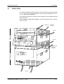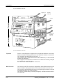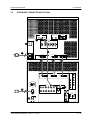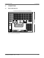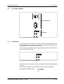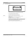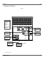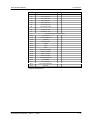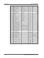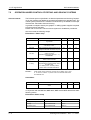
1
MEDIA RECORDER DCR 6024 / 6128 / 6000 Bild im Format 16:9 Planning & Installation Manual Published by BTS Media Solutions GmbH Brunnenweg 9 D-64331 Weiterstadt, Germany P.O. Box 1165 Tel: +49 (0) 6155-870-0 Fax: +49 (0) 6155-870-300 Copyrights Für diese Unterlage behalten wir uns alle Rechte vor (Gemäß DIN 34). Technische Änderungen im Zuge der Weiterentwicklung vorbehalten. BTS Media Solutions GmbH 2001 Copying of this document and giving it to others, and the use or communication of the contents thereof, are forbidden without expressed authority. Offenders are liable to the payment of damages. All rights are reserved in the event of the grant of a patent or the registration of a utility model or design. Liable to technical alterations in the course of further development. Toute communication ou reproduction de ce document, toute exploitation ou communication de son contenu sont interdites, sauf autorisation expressé. Tout manquement à cette règle est illicite et expose son auteur au versement de dommages et intérêts. Tous nos droits sont réservés pour le cas de la délivrance d’un brevet ou de l’enregistrement d’un modèle d’utilité. Sous réserve de modification au cours de l’évolution technique. DCR 6024/6128/6000 Contents CONTENTS Page Safaty Instructions 1. General 1.1 1.2 1.3 1.4 1.5 1.6 Features Overview Mechanical design Machine control Blockdiagram Functional overview 1.6.1 D–6 Standard 1.6.2 DTV Processor DTV 6024 1.6.3 Data Processor DDP 6128 1.6.4 Tape Deck DMS 6000 1.6.5 Scanner Assemply 1.6.6 Control Panel DCH 6024 CP 1.6.7 Data Switch DSW 6000 2. Technical Specifications 2.1 2.2 2.3 2.4 2.5 General Tape Deck / Recording System DTV System 2.3.1 Video 2.3.2 Audio 2.3.3 Cue Audio 2.3.4 Control Data System 2.4.1 Data Input / Output 2.4.2 DPX Monitoring 2.4.3 Control Inputs / Outputs 2.5.1 Tape Deck DMS 6000 2.5.2 DTV Processor DTV 6024 2.5.3 Data Processor DDP 6128 2.5.4 Data Switch DSW 6000 Planning & Installation – Rev. 1 / 7. 2001 1–1 1–1 1–3 1–6 1–7 1–9 1 – 13 1 – 13 1 – 17 1 – 20 1 – 22 1 – 28 1 – 30 1 – 31 2–1 2–1 2–2 2–4 2–4 2–6 2–7 2–7 2–8 2–8 2–8 2–8 2–9 2–9 2 – 10 2 – 11 2 – 11 I Contents DCR 6024/6128/6000 3. Installation 3.1 3.2 3.3 3.4 3.5 3.6 3.7 3–1 Unpacking and repacking Mechanical dimensions Ventilation Mounting 3.4.1 Mounting Tapedeck on Processor 3.4.2 Mounting Tapedeck and Processor side by side 3.4.3 Mounting Versions of DCR 6000 3.4.4 Mounting into a 19-inch cabinet 3.4.4.1 Safety Hazards 3.4.4.2 DCR 6024 built in into a19 inch cabinet 3.4.5 Installing Control Panel as Remote Panel 3.4.6 Installing Control Panel as Local Panel Standard connections DCR 6024 3.5.1 Connect the connection cables Standard connections DCR 6128 3.6.1 Connect the connection cables Standard connections DCR 6000 3.7.1 Connect the connection cables 4. Connections 4.1 4.2 4.3 4.4 4.5 4.6 II 3–1 3–2 3–5 3–8 3–8 3 – 10 3 – 11 3 – 13 3 – 13 3 – 14 3 – 15 3 – 16 3 – 17 3 – 18 3 – 20 3 – 21 3 – 23 3 – 24 4–1 Rear View DMS 6000 Rear View DTV 6024 Rear View DDP 6128 Rear View DMS 6000 Terminal Panel – Tapedeck DMS 6000 4.5.1 AC power terminal unit BD 5146 4.5.1.1 Grounding 4.5.1.2 Mains connection 4.5.2 Processor Interface 4.5.3 Timecode IN/OUT (DTV Mode) 4.5.4 iMCS 4.5.5 Remote Control REM 1, REM 2, REM 3, RS 232C 4.5.6 Waveform Monitoring 4.5.7 Connection Control Panel and headphone with volume adjustment Terminal Panel – Processor DTV 6024 4.6.1 AC power terminal 4.6.1.1 Grounding 4.6.1.2 Mains connection 4.6.2 Tapedeck Interface 4.6.3 Video Analog Monitor Out 4.6.4 Audio Digital In/Out 4.6.5 Audio Monitoring 4.6.6 Audio Sync (48 kHz) 4.6.7 SDTV / NTSC Sync Out 4.6.8 Playback Ref Sync 4.6.9 iMCS 4–1 4–2 4–3 4–4 4–5 4–7 4–7 4 – 10 4 – 11 4 – 12 4 – 13 4 – 14 4 – 15 4 – 16 4 – 17 4 – 19 4 – 19 4 – 20 4 – 21 4 – 22 4 – 23 4 – 24 4 – 25 4 – 25 4 – 25 4 – 26 Planning & Installation – Rev. 1 / 7. 2001 DCR 6024/6128/6000 Contents 4.7 Terminal Panel – Processor DDP 6128 4.7.1 AC power terminal 4.7.1.1 Grounding 4.7.1.2 Mains connection 4.7.2 Tapedeck Interface 4.7.3 DPX Monitor Out (Option) 4.7.4 HIPPI In/Out 4.7.5 Network Interface 4.7.6 IMCS 5. Startup 5.1 5.2 5.3 5.4 5.5 Installation check Switching on 5.2.1 Selecting the HD Standard / Data Mode Selecting Machine Address Control of the Input / Reference signal 5.4.1 DTV Mode 5.4.2 Data Mode Operation 6. Interfaces 6.1 6.2 6.3 RS422 ES - Bus REM 1 ES-Bus Port according to EBU-Tech 3245-E REM 2 IN - RS422A Interface BBE REM 2 OUT – RS422A Interface BBE 7. DTV Applications 7.1 7.2 7.3 7.4 7.5 List of external devices able to control DCR 6024 7.1.1 VTR editors 7.1.2 Telecine controllers Operation under control of Editing- and Graphic Systems Parameter Sheets BBE 900 Parameter Sheets BVE 9000 More Parameter Sheets (in preparation) 8. Data Applications 8.1. Specter / Transfer Engine / Mover (in preparation) 9. Index Planning & Installation – Rev. 1 / 7. 2001 4 – 27 4 – 29 4 – 29 4 – 30 4 – 31 4 – 32 4 – 33 4 – 33 4 – 34 5–1 5–1 5–2 5–4 5–5 5–6 5–6 5–7 5–8 6–1 6–1 6–6 6 – 15 7–1 7–1 7–1 7–1 7–2 7–3 7–4 7–5 8–1 3-3 9–1 III DCR 6024/6128/6000 Safety Instructions SAFETY INSTRUCTIONS Application The DCR 6024/6128/6000 is a digital HDCassette Recorder System designed for recording and playback of video / audio and / or data signals for various DTV– and data standards, according to the SMPTE / D-6 HD-recording format. The DCR 6024/6128/6000 consists of basic modules: Tapedeck incl. Control Panel Warnings! DMS 6000 DCH 6024 CP DTV Processor DTV 6024 Data Processor DDP 6128 Data Switch DSW 6000 To ensure safe operation please observe the following directions: The current and voltages present in this equipment are dangerous. All personnel must at all times follow the safety regulations. Always disconnect power before removing covers or panels. Always discharge high voltage points before servicing. Never make internal adjustments, perform maintenance or service when alone or fatigued. In case of an emergency ensure that the power is disconnected. Any interruption of the protection conductor inside or outside the apparatus, or disconnection of the protective earth terminal, is likely to make this apparatus dangerous. Intentional interruption is prohibited. U® L LISTED PROFESSIONAL VIDEO EQUIPMENT 3S13 / 78MA The DCR 6024/6128/6000 VooDoo Media Recorder is designed accordingly to regulations of the Underwriters Laboratories Inc. Northbrook, Illinois US, certificated and registered under file no.: E184475 (Tapedeck) / E205276 (DTV Processor) U® L E159262 E159262 LISTED UL 1950 3S13 / 78MA (Data Processor) (Data Switch) Conform with the following European directives and CE marked: Safety: Low voltage directive 73/23/EEC, EN 60 950/1997 EMC / EMI: EMC directive 89/336/EEC, EN 55103-1/1996, EN 55103-2/1996 EN 55022/1998 Electromagnetic environment (acc. to EN 55103–1) Warning: This is a class A product. In a domestic environment this product may cause radio interference in which case the user may be required to take adequate measures. Planning & Installation – Rev. 1 / 7. 2001 E4 Warnung: Dies ist eine Einrichtung der Klasse A. Diese Einrichtung kann im Wohnbereich Funkstörungen verursachen; in diesem Fall kann vom Betreiber verlangt werden, angemessenen Massnahmen durchzuführen. I Safety Instructions DCR 6024/6128/6000 EMC: AS/NZS 3548 EMC Environment This unit was designed for use under controlled EMC environment (for example purpose built broadcasting or recording studio), and the rural outdoors environment (far away from railways, transmitters, overhead power lines, etc.). FCC Rules § 15.105 EN 55022 FCC 47 Part 15 Class A This equipment has been tested and found to comply with the limits for a Class A digital device, pursuant to the part 15 of the FCC Rules and EN 55022. These limits are designed to provide reasonable protection against harmful interference when the equipment is operated in a commercial environment. This equipment generates, uses, and can radiate radio frequency energy and, if not installed and used in accordance with the instruction manual, may cause harmful interference to radio communications. Operation of this equipment in a residential area is likely to cause harmful interference in which case the user will be required to correct the interference at his own expense. Connection cables The EMC regulations are only applicable when correctly shielded cables are used for installation of the equipment. This applies to video cables as well as control cables. Corresponding cables can be obtained from Thomson. Run all connection cables in covered cable ducts (risk of stumbling). Mains Voltage The DCR 6024/6128/6000 includes wide range power supply units of 100 – 240 V, so that no changeover is required for different line voltages. Depending on the supply voltage use the proper rated power supply cord. Installation For more details see section 5 ”Installation” in the Planning & Installation manual. Caution! Double-pole or neutral fusing Risk of electric shock. Grounded circuit conductor (neutral) provided with over-current protection. After operation of the protective device, parts of the equipment that remain under voltage might represent a hazard during servicing. Disconnect power before servicing! Fuses of Tapedeck The Tapedeck DMS 6000 is protected by two primary-side fuses (T6.25A / 250V) which are located on the rear panel. When replacing this fuse, make sure that a fuse link of the same type and of the same current rating is used. Never use a mended fuse! Do not short-circuit the fuseholder! II Planning & Installation – Rev. 1 / 7. 2001 DCR 6024/6128/6000 Safety Instructions Fuse of Processor The signal Processors DTV 6024 and DDP 6128 and Data Switch DSW 6000 are protected by an automatic fuse, which is located on the Processor rear panel. During operation The DCR 6024/6128/6000 may only be operated in closed condition. Opening the covers or removing parts with tools may give access to live parts. Therefore the system must be completely disconnected from the mains before any cover is opened. Working on the opened machine If, however, working on the opened machine is inevitable, this may only be done by an expert who is familiar with the dangers involved. Warning ! Beware of high speed rotating video heads. Wear safety glasses! Capacitors ATTENTION! Capacitors may still be charged! If, for example due to a failure, safe operation of the DCR 6024/6128/6000 is no longer possible, take the unit out of operation and secure it against further use. Batteries The Tapedeck contains two backup batteries type Varta CR 1/2 AA Thomson part no. 003 119 100 195 which have to be replaced with batteries of the same type (UL-1642 listed). Battery replacement should be done by Thomson service personnel only. Planning & Installation – Rev. 1 / 7. 2001 III Safety Instructions IV DCR 6024/6128/6000 Planning & Installation – Rev. 1 / 7. 2001 DCR 6024/6128/6000 1. GENERAL 1.1 FEATURES 1.1.1 GENERAL 1. General Digital film and the 1080p universal mastering format are increasingly important in post production applications. Besides the digital HD video formats the data format using SMPTE–rated DPX ( digital picture exchange) file format for uncompressed storage and transport of picture information is required. This data format allows higher resolution than specified in video formats with similar freedom in transfer characteristic, color space and so on. The DCR 6024/6128/6000 supports the HD video formats (1920x1080) as well as data recording of DPX picture information. Using the same tapedeck and different processors for DTV and data applications the system can be configured for the requested application. With the addition of the data switch the same tapedeck can be used to record data or digital HD video in many formats. 1.1.2 HDTV RECORDER DCR 6024 The DCR 6024 is a digital component HDTV Cassette Recorder designed for acquisition, production, postproduction and archiving of video and audio signals for various HD-standards, according to the SMPTE/D-6 HD-recording format. Operating in HD standards HD-SDI IN / OUT SMPTE 292M: 1920 x 1080 @ 24p 1920 x 1080 @ 23.97p 1920 x 1080 @ 25p Progressive modes 1920 x 1080 @ 24sF 1920 x 1080 @ 23.97sF 1920 x 1080 @ 25sF ”segmented frame” modes 1920 x 1080 @ 60i 1920 x 1080 @ 59.94i 1920 x 1080 @ 50i 2:1 interlace modes 10 (60i), 12 (24p, 25p, 24sF, 50) digital Audio in- and outputs according to AES Standard Crossplay between varoius modes Timecode conversion in crossplay modes Visible search 15 times regular speed Broadcastable slowmotion range – 0.25 to + 0.25 regular speed Automatic Tracking adjustment Automatic playback equalization Integrated two machine editor Planning and Installation – Rev. 1 / 7. 2001 1–1 1. General DCR 6024/6128/6000 Control Panel with slot for personal card to store individual setups Integrated ASTC (Audio Sector Time Code) 1 Video Component output analog R/G/B/S switchable to Y/PR/PB for Monitoring. In 24(23.97)p mode the output is switchable to 60i (2/3 pulldown) Remote control interfaces: ESBUS , RS422 SONY protocol, iMCS Option BD 5402: 2 Audio analog outputs for monitoring (L/R) 1 Headphone output 1.1.3 DATA RECORDER DCR 6128 Data recorder system for recording and playback of image data and general purpose data (instrumentation recording) Data rates up to 128 MBtes/sec 128 MBytes/sec in instrumentation mode (without rewrites) 100MBytes/sec in Hippi mode (with rewrites) 500 GBytes max capacity on large cassette Hippi serial optical interface for data transfer iMCS remote control for links to telecines and other Thomson film imaging products Flexibilty to adopt future high speed data interfaces Option BD 5456 DPX monitor for dispaying DPX data on a XGA monitor (1024x768) 1.1.4 DIGITAL FILM APPLICATION SYSTEM DCR 6000 Digital Film Applications (DFA) system which combines the DCR 6024 (H)DTV recorder and the DCR 6128 Data Recorder to a versatile, switchable system. A DSW 6000 Data Switch allows to use the DMS 6000 tapedeck for both DTV and data applications. A changeover from data to DTV mode can be done within seconds. 1–2 Planning and Installation – Rev. 1 / 7. 2001 DCR 6024/6128/6000 1. General 1.2 OVERVIEW 1.2.1 HDTV RECORDER DCR 6024 The DCR 6024 consists of two basic modules: Tapedeck incl. Control Panel DTV Processor DMS 6000 DCH 6024 CP DTV 6024 Tapedeck Control Panel Processor Fig. 101: HDTV Recorder DCR 6024 Planning and Installation – Rev. 1 / 7. 2001 1–3 1. General 1.2.2 DCR 6024/6128/6000 DATA RECORDER DCR 6128 The DCR 6128 consists of two basic modules: Tapedeck incl. Control Panel Data Processor DMS 6000 DCH 6024 CP DDP 6128 Tapedeck Control Panel Processor Fig. 102: Data Recorder DCR 6128 1–4 Planning and Installation – Rev. 1 / 7. 2001 DCR 6024/6128/6000 1.2.3 1. General DFA RECORDER SYSTEM DCR 6000 The DCR 6000 consists of two basic modules: Tapedeck incl. Control Panel DMS 6000 DCH 6024 CP Data Processor DDP 6128 DTV Processor DTV 6024 Data Switch DSW 6000 Tapedeck Control Panel Data Switch DTV Processor Data Processor Fig. 103: DFA Recorder System DCR 6000 Planning and Installation – Rev. 1 / 7. 2001 1–5 1. General 1.3 Housing DCR 6024/6128/6000 MECHANICAL DESIGN The housings of the Tapedeck and Processor are made of aluminium alloy which is coated inside with alodine to prevent electrostatic discharge influences. Modules can be locked mechanically together and unlocked for easy transport. 19-inch rack installation kit for tapedeck and processors are available Order no.: BD 5197 000 175 602 211 for tapedeck BD 5198 000 175 602 310 for DTV processor BD 5199 000 175 602 410 for data processor The rackmount kit for the tapedeck contains telescopic rails for easy access to tapedeck mechanics. Tapedeck and Processor are provided with four handles which facilitate transport of the machine. For service works, the Tapedeck can be hinged upwards, being hold by two locking mechanism. 1–6 Planning and Installation – Rev. 1 / 7. 2001 DCR 6024/6128/6000 1.4 1. General MACHINE CONTROL The control of the DCR 6024/6128/6000 is based on a user-friendly menudriven concept. The menus are selected via 12 dedicated keys. All menus (except Setup, Diagnostics and Editor) are designed without any sub menus to ensure easy handling. The menues are application sensitive, Depending on selected modes (data or video) and installed options there are different menues and controls available. 12 softkeys control different functions in each menu replacing a high number of dedicated keys. All analog adjustments are done by a digipot which function varies with the different menus (for further informations see chapter 4 “Menu Control” in the “Operating Instructions” manual). A unique feature for VTR’s is the availability of a credit- card sized personal card which can be inserted in a slot on the control panel. All machine parameters and setups accessible from the control panel can be stored on this card. Information are stored at this card in a S-RAM buffered by a 3 V lithium battery so that it can be loaded everywhere into the recorder. If required, the stored machine setups and adjustments can then be recalled. Planning and Installation – Rev. 1 / 7. 2001 1–7 1. General 1–8 DCR 6024/6128/6000 Planning and Installation – Rev. 1 / 7. 2001 DCR 6024/6128/6000 1. General 1.5 BLOCK DIAGRAM 1.5.1 TAPEDECK DMS 6000 +44V BD 5195 +15V AC Power Supply +13V +15V +5V iMCS –2V M –5.2V –15V Main Erase Head DCH 6024 KE TC X X CTL X BY 5110 BY 5112 Record Pre–Equalizer PLAYBACK Equalizer Scanner Power Supply Shuttle Motor Capstan Motor CUE X M Scanner BY 5113 M Shuttle Motor BY 4019 Motor Power Amplifier BY 5115 Cue/ CTL/ Timecode Control Analog BY 5160 SCU System Control Unit BY 5165 REM 2 Clock Recovery Record Data Play Data RS232 Diagn. Servo WFM/Trigger TC In/Out BX 5121 Head Phone MCU Control Data TCU SIU CCU REM 1 iMCS Active Terminal Board To Processor Fig. 104: Block Diagram Tapedeck DMS 6000 Planning and Installation – Rev. 1 / 7. 2001 1–9 1. General 1.5.2 DCR 6024/6128/6000 DTV PROCESSOR DTV 6024 To Tapedeck +/– 18V I/O Buffer +/– 12V Play Data Record Data +5V VDFM – 1 VOUT Video Frame Memory Control Data Video Out Processor +3.3V Power Supply AC IN –5.2V CODC – 1 – 4 VINP SCCV Video Digital In (Serial) Reed – Solomon Coder/Decoder Video Scanning Converter Input Processor SCCV VDFM – 2 Video Digital Out Serial 1–3 SDTV Sync Out Video Frame Memory Scanning Converter Video Monitor Out Analog AINP Audio Digital In 5/6 x AES Stereo 48 kHz Out Audio Input Processor AOUT Audio Digital Out 5/6 x AES Stereo SYSC Processor System IMCS Control Audio Output Processor Audio Monitor Out R AMON Audio Analog Out L Fig. 105: Block Diagram DTV Processor DTV 6024 1 – 10 Planning and Installation – Rev. 1 / 7. 2001 DCR 6024/6128/6000 1.5.3 1. General DATA PROCESSOR DDP 6128 To Tapedeck ÇÇÇÇÇÇÇÇÇÇÇÇÇÇÇÇÇÇ ÇÇÇÇÇÇÇÇÇÇÇÇÇÇÇÇÇÇ ÇÇÇÇÇÇÇÇÇÇÇÇÇÇÇÇÇÇ ÇÇÇÇÇÇÇÇÇÇÇÇÇÇÇÇÇÇ ÇÇÇÇÇÇÇÇÇÇÇÇÇÇÇÇÇÇ ÇÇÇÇÇÇÇÇÇÇÇÇÇÇÇÇÇÇ ÇÇÇÇÇÇÇÇÇÇÇÇÇÇÇÇÇÇ ÇÇÇÇÇÇÇÇÇÇÇÇÇÇÇÇÇÇ ÇÇÇÇÇÇÇÇÇÇÇÇÇÇÇÇÇÇ ÇÇÇÇÇÇÇÇÇÇÇÇÇÇÇÇÇÇ ÇÇÇÇÇÇÇÇÇÇÇÇÇÇÇÇÇÇ ÇÇÇÇÇÇÇÇÇÇÇÇÇÇÇÇÇÇ I/O Buffer Data Record Play Data Control Data CORE2 CORE1 ÇÇÇÇÇÇÇÇÇÇÇÇÇÇÇÇÇ DPMB ÇÇÇÇÇÇÇÇÇÇÇÇÇÇÇÇÇ ÇÇÇÇÇÇÇÇÇÇÇÇÇÇÇÇÇ ÇÇÇÇÇÇÇÇÇÇÇÇÇÇÇÇÇ ÇÇÇÇÇÇÇÇ ÇÇ ÇÇÇÇÇ ÇÇÇÇÇÇÇÇÇÇÇÇÇÇÇÇÇ ÇÇÇÇÇÇÇÇ ÇÇÇÇÇÇÇÇÇÇÇÇÇÇÇÇÇ ÇÇ ÇÇÇÇÇ ÇÇÇÇÇÇÇÇÇÇÇÇÇÇÇÇÇ ÇÇÇÇ ÇÇÇÇÇ ÇÇÇÇÇÇ ÇÇÇÇÇÇÇÇÇÇÇÇÇÇÇÇÇ ÇÇ ÇÇ ÇÇÇÇÇÇ ÇÇÇÇÇÇÇÇÇÇÇÇÇÇÇÇÇ ÇÇ ÇÇ ÇÇÇÇÇÇÇÇÇÇÇÇÇÇÇÇÇ ÇÇ ÇÇÇÇÇÇ ÇÇ ÇÇ ÇÇÇÇÇÇÇÇÇÇÇÇÇÇÇÇÇ ÇÇ ÇÇÇÇÇÇ ÇÇ ÇÇÇÇÇÇÇÇÇÇÇÇÇÇÇÇÇ ÇÇ ÇÇ ÇÇÇÇÇÇ ÇÇ ÇÇÇÇÇÇÇÇÇÇÇÇÇÇÇÇÇ ÇÇÇÇÇÇ ÇÇ ÇÇ ÇÇ ÇÇÇÇÇÇÇÇÇÇÇÇÇÇÇÇÇ ÇÇÇÇÇÇ ÇÇ ÇÇ ÇÇÇÇÇÇÇÇÇÇÇÇÇÇÇÇÇ ÇÇ ÇÇÇÇÇÇÇÇÇÇÇÇÇÇÇÇÇ ÇÇ ÇÇÇÇÇÇÇÇÇÇÇÇÇÇÇÇÇ ÇÇÇÇÇÇ ÇÇ ÇÇÇÇÇÇÇÇÇÇÇÇÇÇÇÇÇ ÇÇ ÇÇÇÇÇÇ ÇÇÇÇÇÇÇÇÇÇÇÇÇÇÇÇÇ ÇÇÇÇÇÇ ÇÇ ÇÇÇÇÇÇÇÇÇÇÇÇÇÇÇÇÇ ÇÇÇÇÇÇÇÇÇÇÇÇÇÇÇÇÇ ÇÇÇÇÇÇÇÇÇÇÇÇÇÇÇÇÇ ÇÇÇÇÇÇ ÇÇ ÇÇÇÇÇÇÇÇÇÇÇÇÇÇÇÇÇ ÇÇÇÇÇÇ ÇÇ ÇÇÇÇÇÇÇÇÇÇÇÇÇÇÇÇÇ ÇÇÇÇÇÇ ÇÇ ÇÇÇÇÇÇÇÇÇÇÇÇÇÇÇÇÇ ÇÇ ÇÇÇÇÇÇÇÇÇÇÇÇÇÇÇÇÇ ÇÇ ÇÇÇÇÇÇÇÇÇÇÇÇÇÇÇÇÇ ÇÇ ÇÇ ÇÇÇÇÇÇÇÇÇÇÇÇÇÇÇÇÇ ÇÇÇÇÇÇÇ ÇÇÇÇÇ ÇÇ ÇÇÇÇÇÇÇÇÇÇÇÇÇÇÇÇÇ ÇÇ ÇÇÇÇÇÇÇÇÇÇÇÇÇÇÇÇÇ ÇÇ ÇÇÇÇÇÇÇÇÇÇÇÇÇÇÇÇÇ ÇÇÇÇÇÇ ÇÇ ÇÇÇÇÇÇÇÇÇÇÇÇÇÇÇÇÇ ÇÇÇÇÇÇ ÇÇ ÇÇÇÇÇÇÇÇÇÇÇÇÇÇÇÇÇ ÇÇÇÇÇÇ ÇÇ ÇÇÇÇÇÇÇÇÇÇÇÇÇÇÇÇÇ ÇÇÇÇÇÇÇÇÇÇÇÇÇÇÇÇÇ EEPROM +5V +3.3V Power AC IN Supply –5V (Manufacture Data Storage) PWRS (Voltage Control) 12C BUS DPSC IONT iMCS IP ÇÇÇÇÇÇÇ ÇÇÇÇÇÇÇ ÇÇÇÇÇÇÇ ÇÇÇÇÇÇÇ SIND CPU BUS DMON MONI HPIF HIPPI Fig. 106: Block Diagram Data Processor DDP 6128 Planning and Installation – Rev. 1 / 7. 2001 1 – 11 1. General 1 – 12 DCR 6024/6128/6000 Planning and Installation – Rev. 1 / 7. 2001 DCR 6024/6128/6000 1.6 1. General FUNCTIONAL OVERVIEW For details refer to block diagram 1.6.1 D–6 STANDARD Tape motion D-6 Track pattern AUDIO CUE TRACK 0,7 mm Video Video sector Video/Audio gap 19 mm Audio sector 1st record 1 Cluster with 8 tracks Audio sector 2nd record 0,5 mm CONTROL TRACK TIME CODE TRACK 0,5 mm Fig. 107:D–6 Track pattern video Tape motion D-6 Track pattern AUDIO CUE TRACK (not used) 0,7 mm Data sector HAI Helical Address Information 19 mm Data 1 Cluster with 8 tracks Rewrite area 0,5 mm 0,5 mm CONTROL TRACK Track–Set–ID and LAI (Longitudinal address information) Fig. 108:D–6 Track pattern data Helical tracks The track pattern of the recorder contains the helical tracks with the video and audio sectors (DTV mode) and rewrite area (data mode) divided in clusters of 8 tracks each. It is based on azimuth recording with a track pitch of 22 m which allows a max recording capacity of 64 min or 500 GBytes with a L-type cassette. The clusters are separated by guard bands from each other, allowing proper erasement of the individual clusters with a single flying erase head for each cluster. One field is the minimum edit distance for video audio and data in DTV mode. It is divided into six (24/25 Hz) or five (30 Hz) clusters respectively. In data mode the sytem uses the 25 Hz mode internally. Planning and Installation – Rev. 1 / 7. 2001 1 – 13 1. General DCR 6024/6128/6000 In DTV mode, twelve (ten) digital audio channels are independent editable in six (five) stereo pairs. An edit gap between audio and video sectors allows a separate editing of audio and video. The audio sectors are recorded on the top (1st record) and on the bottom (2nd record) of the helical track for additional error correction. In data mode there is a special rewrite area at the beginning of each track. In this area, sync blocks with detected errors during recording will be written again. An additional Sync block located at the beginning of data area contains the HAI (Helical Address Information). In this block all control info about the content of helical tracks like TOC (Table Of Content), and packet info is written. Longitudinal tracks One longitudinal analog audio cue track (only used in DTV mode), the control track and the time code track complete the track configuration of the D-6 tape format. The recorder DCR 6024 is capable of recording various progressive, “segmented frame” or interlace standards. HD Standard (frame rate) selection is made in the ”SETUP” main menu. The selected standard is indicated by the system status indicators at the Control Panel, LED ”frame rate” (either 24/25 Hz or 30 Hz). In data mode the timecode track is used to locate and identfy data and system tracks of data recordings. On tape, a standard 25 fps SMPTE timecode is used. For the internal control interface this information is translated into a TSID (Track Set ID). each timecode frame is one TSID. This TSID is used for display, internal and edit controls. Timecode 02:00:00:00 is coverted into TSID 00000 Each new partition starts with an offset of 02:00:00:00 The UserBits contain information about type of tracks, file–no., record mode, partition–no. and tape length. D-6 video casette The DCR 6024 uses 11 µm thick D-6 tapes in three different cassette sizes S, M, with a maximum recording time of 64min. The magnetic tape specifications (type of cassette, tape thickness) are detected and interpreted automatically after the cassette has been loaded. Other 19 mm cassettes ( D-1 or D-2 type), not coded according to the D-6 format will be rejected by the DCR 6024 recorder. Another coding of the cassette prevents unintentional erasure of the cassette. Use only tapes specified by Philips and Toshiba. D-6 Recording format 1 – 14 It uses the D-6 recording format, developed and supported by Philips Digital Video Systems and Toshiba. This format is based on a digital segmented-field video recording system with multichannel audio using a 19 mm cassette housing, ( S, L and M) with enhanced 11m MP tape.The robust segmented tape format with the high sophisticated digital Processor guarantees a reliable production and transfer recording standard for the various standards. Planning and Installation – Rev. 1 / 7. 2001 DCR 6024/6128/6000 High quality recording and playback 1. General The DCR 6024/6128/6000 offers a confidence playback facility for video and audio tape monitoring during record in DTV mode. In data mode, confidence playback is used to check the recorded data and rewrite if necessary. Digital recording and playback in conjunction with sophisticated error correction result in excellent picture and sound quality in DTV mode. Even after 20 tape dubbing generations there will be no noticeable loss of quality. Error Correction The DCR 6024 includes a very powerful error correction facility with a total output error rate of 10 -11. A two step error correction system, based on the Reed Solomon Code is implemented to correct data reading errors. There are two types of errors: Single errors Burst errors In data mode (DCR 6128) the error correction capabilities are increased once more. In conjunction with a rewrite function, controlled by the result of confidence playback functions the corrected bit error rate (BER) will be in the range of 10 E–17. In both modes the playback quality is checkable by the ”Channel Condition” indicators (LEDs) and/or by the display of the ”ADJUST” menu. Single error correction The ”Inner-Code” is used to correct up to 7 single errors in each datablock of 227 bytes (DTV mode) or 230 Bytes in data mode. With the restriction that the off tape bit error rate is smaller than 10 -4 and no burst errors occur, the residual error rate after ”Inner correction” will be less than 10 -16. This is about one million times better than D-1 format VTR performance. Burst error correction Due to scratches and tape drop outs, not only single errors but also large burst errors can occur. To overcome this problem the DCR 6024/6128 has a powerful ”Outer-Code” too. Extensive burst errors up to 141 648 bytes of data could be corrected in DTV mode by ”Outer correction”. That is 25 times more than a D-1 format recorder can.Using advanced integration techniques the most powerful error correction of existing digital video standards is implemented in the DCR 6024. In data mode (DCR 6128) the “Outer correction” is more than twice as powerful as in DTV mode. In conjunction with the rewrite function during record the corrected BER will be in the range of 10 E–17. Concealment (DTV–mode) If the capacity of the error correction system is exceeded by larger defects, an error concealment function becomes active which covers the defective data. Planning and Installation – Rev. 1 / 7. 2001 1 – 15 1. General iMCS DCR 6024/6128/6000 The iMCS control interface is designed as Cheapernet-based control link (IEEE 802.3 standard) between machine(s) and control panel(s). This interface can be used to interconnect up to four machines. Such a cluster configuration allows the design of cost-effective operating configurations as only one control panel is required to operate several machines.The integrated two-machine editing system of the DCR 6024 uses the iMCS (2-machine cluster) as a control link when editing with two DCR 6024. In data mode (DCR 6128) the iMCS interface is used to control the data recorder from telecine controllers or workstations. 1 – 16 Planning and Installation – Rev. 1 / 7. 2001 DCR 6024/6128/6000 1.6.2 1. General DTV PROCESSOR DTV 6024 Digital Video Interfaces Digital serial input signal is a serial data stream composed of digital samples of a component video signal Y / PR / PB. The signal formats for video are described in the SMPTE 274M. SMPTE 292M describes the signal parameters for serial interfaces. The system uses an 10(8) bit quantization for Luminance and a 8 bit quantization for chrominance. Video Record SCCV Scanning Converter The digital serial video input signals are fed to the board SCCV. The signal is converted from serial into parallel. Progressive signals are converted into a segmented signal. For progressive and segmented frame modes (24, 25, 23.97 fr/sec) 2 LSB bits from the 10 bit Y are separated and stored in a memory and inserted as lines of the frame. In case of 8 bit signal processing and 10 bit input, a rounding process is integrated. VINP Video Input Processor The selected input data are fed to the serial parallel converter and converted into 4 channel parallel luminance data (Y) and 4 channel chrominance data (Pb/Pr). After line shuffling, parity bytes for the outer error correction coding are added. CODC 1-4 Inner Coder/Decoder The coded data are fed to the board CODC. On this board, the coded data are further shuffled in a field basis. After mixing with the audio data, parity bytes for the inner error correction coding are added. In the channel encoder, the eight bits data are transformed into 12 bits data, then the sync words are added. A head delay compensates for the timing difference between each channel, caused by the difference of the mechanical position of each head on the headwheel. Finally, the data are converted to serial data (8 channel record data, 2 bit parallel), and sent to the Tapedeck as ”record data” via the buffer board I/O1. AES-/EBUStandard The digital audio interface meets the AES-/EBU- standard AES 3, 1992. A total of 12 (10) channels or 6 (5) stereo pairs is available for the digital recording of audio signals, it uses a sampling frequency of 48 kHz and 20 to 24 bit linear quantization. Planning and Installation – Rev. 1 / 7. 2001 1 – 17 1. General Audio Record DCR 6024/6128/6000 AINP Audio Input The recording signals are fed to the board AINP. The segment memory stores the recording signals temporarily to establish the segmented recording signal format, which corresponds to the audio data block for error correction coding. Readout signal from the segment memory is supplied to the Read-Solomon encoder which calculates outer parities for the audio data. The encoded output signal is stored in the shuffling memory. This memory generates the first and the second recording data with different shuffling schemes in a unit of inner code word. The first and second recording data are transmitted to the board CODC to be multiplexed into video data. Video Play CODC Encoder / Decoder The serial data are fed to the decoder board CODC via the board I/O1 from the Tapedeck. In this board, the serial data are converted into parallel form, and fed to the TBC (Time Base Corrector) to reject time base errors. The sync pattern are detected from the reproduced data in the sync detector circuit. The channel decoder converts the 12-bit modulated data into 8-bit data. The inner decoder performs detection and correction of errors. The audio data are separated after inner error correction. VDFM Video Playback Processor In the board VDFM, the field deshuffling is done in a field basis, then the outer error correction is carried out. VOUT Video Out Processor The corrected data are fed to the board VOUT. In the board VOUT, the data is rearranged into the original data arrangement after the line deshuffling and channel deshuffling.The concealment circuit is provided to interpolate the data in case that the data are not fully corrected by using the outer parity. By using the surrounding non-erroneous pixels the erroneous data are interpolated. The video sync data are added to the blanking interval then the data are converted from parallel form to serial form, and fed to the board SCCV. If the digital I/O option (available only for 60i and 59.94i) is installed the digital signal is fed to the output connector. SCCV Scanning Converter The digital parallel signal coming from the VOUT board is converted from a segmented format to the selected output format. Lines containing 2bit Y are stored in a memory and added to the Y signal. A parallel to serial converter generates the output signal according to SMPTE 292M standard. A video monitoring circuit generates an analog output signal (Y, PR, PB, Sync) or R, G, B, Sync according to the selected standard. Audio Play AOUT Audio Out Processing The board CODC supplies reproduced audio data to the board AOUT.In the board AOUT, the reproduced data and inner decoder flags are stored in the deshuffling memory. Storing operation is permitted when the reproduced data are likely to have correct inner code block addresses. When the storing is inhibited, a new/old flag is set to ”1” for corresponding inner code block in order to avoid misdetection by older correct inner code block.The first and the second recording data are readout from the deshuffling memory by turns in a unit of symbol. Then, for each data symbol, optimum one is selected to achieve optimum outer code word. This code word 1 – 18 Planning and Installation – Rev. 1 / 7. 2001 DCR 6024/6128/6000 1. General is fed to the Reed-Solomon decoder for error detection and correction. The decoded output data are stored in the segment memory to get an audio data sequence. The error concealment and the level control are applied to this sequence. (AES/EBU interface encoding is applied to the audio data, and the encoded data are output through rear panel connectors as audio digital output signals) Analog Audio Option, Audio Monitoring Option Two channels are available on the audio monitor output through the output connectors of the rear panel and the headphone jack in the Tapedeck.The monitor signals can be selected from the input or reproduced audio signals, the aux input signal, the cue record signal and the cue playback signal. System Control The SYSC board consists of System Control block and Sync Generator block. The System Control block controls the system, communicates with the Tapedeck and outputs superimpose data. The sync generator block consists of a diverse sync signal generator, a system clock regenerator, a playback sync signal phase adjuster, a NTSC / PAL sync signal generator and a channel clock generator circuits. The timing of every synchronizing signal is completely switchable to meet each HD standard. Planning and Installation – Rev. 1 / 7. 2001 1 – 19 1. General 1.6.3 DCR 6024/6128/6000 DATA PROCESSOR DDP 6128 To prevent major modifications in the tapedeck, one of the existing video modes is for data recording. When in data mode, the tapedeck runs internally in a video mode (50Hz). So all tapedeck functions like servos, timecode units can be remained unchanged. Only the system software has to be modified for data version. Record Path HPIF Board (HIPPI–Interface) The optical signal is fed from the input to this board. This board is responsible for communication with external Hippi devices. A conversion from optical serial signal to electrical parallel signal is made. A buffer of 128 MBytes allows a flexible handling of incoming data stream. The Hippi header is detected and analyzed. The header is removed and the data is provided to DPSC board. DPSC Board On the DPSC board the internal data controls are processed. Control information like helical address information (HAI), table of content (TOC), partition information (PSIT) is generated and inserted in data stream. All required clock generators are located on this board. The incoming data packet is distributed and segmented into 8 channels. This board contains also the system control unit. CORE Board This board is responsible for the standard digital recorder signal processing steps. The functions are comparable with the CODC board of the DTV processor. Each board contains 4 channels, so two identical boards are used in the data processor. The Reed Solomon error correction encoder adds check bytes to the data bytes. A rewrite memory stores data and inserts this data again if a rewrite due to error rate is required. After channel coding and conversion from parallel to 2bit serial mode, the data is fed to the tapedeck. Play Path CORE Board The playback data stream (8channels) is fed to the two boards. Similar functions compared to the CODC board are implemented: Channel decoding Sync detection Error detection and correction. For the rewrite function, a error information for rewrite decision is generated. DPSC Board The DPSC board extracts and processes all control information that was inserted in the data stream during record (HAI, TOC). The data signal is combined from the 8 channels. 1 – 20 Planning and Installation – Rev. 1 / 7. 2001 DCR 6024/6128/6000 1. General HPIF Board The playback data signal is prepared for Hippi transfer. signal information (size) is analyzed and a Hippi header is generated. Communication with Hippi destination device is started and data is sent via optical transceiver. For playback mode the same buffer memory of 128 MBytes is used. DPX Monitoring (Option) If the incoming / outgoing data stream is detected as DPX data, the signal is fed to the DPX monitoring board. This board is located on the HPIF –board. The out put of this board is a standard XGA signal (1024x768 / 80Hz). The DPX data is converted into an XGa signal. If the resolution of DPX signal is lower than XGA resolution, the complete picture is displayed. If the resolution is higher, the resolution is reduced by skipping lines and pixels. Because this is only a monitoring feature boarders may appear on the screen depending on DPX resolution. In record mode, this board is connected to the input data stream, inplayback mode, the board is connected to the output data stream. DPCU System Control The system control is responsible for the control of all boards and the communication with tapedeck via iMCS. For service mode a RS232 serial port is installed. Software updates can be done using this port to reprogram the flash Eproms. Planning and Installation – Rev. 1 / 7. 2001 1 – 21 1. General 1.6.4 DCR 6024/6128/6000 TAPEDECK DMS 6000 Auto-Tracking Automatic Tracking System This recorder has a permanent auto tracking function which means that the head tracking will be kept on the track during playback continuously. This is accomplished by monitoring the RF envelope signal and automatic adjustment of the head track position. Alternatively it is possible to perform a manual tracking adjustment.Both adjustment facilities can be selected in the ”ADJUST” menu. Equalizer Adjust Automatic Playback Equalizer Adjustment For optimal playback of a tape that was recorded on another machine, it might be necessary to equalize the frequency response in the playback signal path. This results in a digital data stream which exhibits minimum error rates and consequently gives concealment-free (error concealment) video and audio signals. The adjustment is effected in the ”ADJUST” or in the ”HOME” menu. Slow Motion The use of four field stores allows broadcastable slow motion picture playback at a speed of - 0.25 to +0.25 times of normal speed, around zero. Visible search Visible search is possible even at 15 times the normal speed, in both directions. Still frame Moreover, a high-quality still picture reproduction generated from the field store is provided. Jogging The jogging mode serves to locate a certain picture in slow motion.The tape speed ( -0.25 to + 0.25 from regular speed) is proportional to the ”multi function dial” speed. Analog Cue-Channel (DTV mode) 1 – 22 Slow rotation slow speed Fast rotation fast speed Stand still tape standstill In addition to the twelve (ten) digital audio channels the DCR 6024 has one analog longitudinal audio channel for recording cue signals. The cue channel can be used to record a signal from an internal or an external (optional) audio signal source.When recording is made using both the digital audio channels and the analog cue channel, the cue channel signal can be used as a reference for editing the digital audio signals.Moreover, the audio cue track enables audio playback during rewinding and at slow motion speeds.The audio cue track is adjusted in the ”CUE TRACK” menu. Planning and Installation – Rev. 1 / 7. 2001 DCR 6024/6128/6000 Timecode System (DTV mode) 1. General For automatic editing the DCR 6024 must provide a definite identification for each frame.For this purpose, a continuous analog longitudinal timecode (LTC) is recorded on the timecode track. In addition, the machine records and reads the Audio Sector Timecode (ASTC) . In crossplay modes 24p, sf and 25p, sf a switchable timecode conversion is implemented. This allows to playback 24p, sf tapes in a 25p, sf mode and vice versa. If timecode crossplay is switched on, the timecode on tape will be translated into an absolute frame number. The frame number will be used to generate the timecode in the currently selected standard. All interfaces (iMCS, RS422, TC–Out/XLR) will follow the crossplay mode. Two-Machine (Master-Slave) Editing System Record Path Internal Editing system (DTV mode) The integrated two-machine (Master-Slave) editor serves for automatic edit execution. It is operated via the ”EDITOR” menu. All common edit modes (Normal, Insert and Assemble) are available. Edit timing is realized by means of IN and OUT marks.A preview function is provided to permit edit simulation. Sequential playback can be selected in the ”EDITOR” menu. BX 5121 Active Terminal Board (Input Buffer) The serial 8 channel record data (2 bit parallel) coming from the Processor is clocked by clock 7 in the input buffer on the active terminal board (I/O buffer) BX 5121. Clock 7 is used for timing reference. All signals have ECL level. BY 5113 Preequalizer On the preequalizer BY 5113 the data will be converted into a one bit serial data stream (LSB first). A phase locked loop circuit (PLL) generates the necessary double frequency channel clock. The following differential amplifier controls the output level and can be gated by the REC_GATE 0-7 command. The next differential amplifier is the real preequalizer boosting the high frequencies to compensate H.F. loss of the record heads. The preequalizer parameters are controlled by two values, C1 and C2. Then the signal is buffered by a DC controlled 50 Ω output stage.(Separate control voltages are provided for heads 0o and 180o heads via I2C-bus.) Record current and preequalizer C are adjustable from the control panel (AdjustMenu), preequalizer C2 is a fixed value adjusted in the factory or by service engineer. The eight signals are fed to the scanner assembly. Play Path BY 5110 Equalizer The play signal from the scanner is fed to an equalizer circuit to compensate the frequency response of the head-tape system. Thus the equalizer boosts both the high and low frequencies and can be controlled by two parameters available on the control panel, see menu ”Adjust” channel equalizer parameter: I/D and P/D2. Further more the equalizer contains a signal rectifier to generate an rf-envelope signal which is used for auto-tracking and for waveform-monitoring. The rf-envelope signal can alter due to different tapes, recordings and head conditions. Planning and Installation – Rev. 1 / 7. 2001 1 – 23 1. General DCR 6024/6128/6000 The following low pass filter BX 5111 cuts noise above 80 MHz. To have a constant output level for the quantized feedback circuit, the level is regulated by an AGC (Automatic Gain Control Circuit). BY 5165 Clock Recovery The clock recovery is a PLL circuit which regenerates the clock signal, to be used to clock the data. The VCO is tuned via I2C-bus for various Standards and data rates in the operation modes play, shuttle, variable. After clocking the data signal is digital in time and level and is parallelized into 2 bits which are fed to output buffer of the active terminal board BY 5121. BX 5121 Active Terminal Board The active terminal board contains ECL buffers for the playback clock and data signal. Cue Audio Record From all of the reproduced digital audio data and the aux input data, cue record signal is generated and transmitted to the Tapedeck. The signal, transmitted in a digital form to the cue control analog board BY 5115, is converted back to an analog signal to be recorded on tape. Before recording level and frequency response are aligned and bias is added. Play The cue playback signal passes through a level control and equalizer stage before it is converted back to a digital form on the cue control analog board and transmitted to the Processor. Timecode The time code signal, generated in the system control unit BY 5160, is recorded on tape after adding bias on the board cue control analog BY 5115. The playback signal is fed via the board cue control analog BY 5115 to the waveform monitor stage of the board scanner power supply BY 5112 and after clipping to the system control board BY 5160. During record, a signal derived from the record current is fed to the waveform monitor stage. Control Track The control track signal, generated in the system control unit BY 5160, is recorded on tape after adding bias on the board cue control analog BY 5115. The playback signal is fed via BY 5115 board to to the waveform monitor stage of the board scanner power supply BY 5112 and after clipping to the system control unit BY 5160. During record, a signal derived from the record current is fed to the waveform monitor stage. Main Erase 1 – 24 The main erase stage is located on the cue control analog board BY 5115 and is active during crash and assemble record mode to erase the complete tape. Planning and Installation – Rev. 1 / 7. 2001 DCR 6024/6128/6000 Scanner Power supply 1. General The scanner power supply board BY 5112 contains the following functions: 1. Two switch mode power supplies (+5V and –12V/–7V) for the scanner recordand play-back amplifiers. 2. Thermal protection of record amplifiers by detecting the headwheel rotation. If the rotation speed of the headwheel goes down, the record mode is cut off. This prevents thermal damages of the record amplifiers. 3. Erase oscillator (30 MHz) for the flying erase heads. 4. Head switch logic realized by a FPGA. The FPGA generates all the timing signals for the record and play process in the RF- path as well as EE information for the Processor in simulation mode. 5. Processing of waveform monitoring signals. Control System iMCS The control system of the recorder DCR 6024 is conceived as a multi Processor system.The main components of the control system are connected via the serial iMCS bus system with each other ( iMCS = internal machine communication system). This bus is based on standard IEEE 802.3 (ETHERNET). Because of the cable deviating from the ETHERNET-Standard, the bus system is confessed also under name CHEAPERNET. The maximal cable length is specified with 185m. The participants in the iMCS system are: Tapedeck / System Control Unit BY 5160 Control Panel DCH 6024 CP DTV Processor / System Control Unit SYSC Data processor / System Control Unit DPCU Up to four DCR 6024 can be controlled within one iMCS net. Individual recorder station addresses can be set up by local address switches, see chapter 5.3 ”Startup”. The system control board BY 5160 is divided into two sections, BY 5161 and BY 5162. The overall function can be separated into seven main groups: Central Control Unit CCU Gateway (Serial I/O Unit) GW Timecode Unit TCU Motor Control Unit MCU Digital Motor Control DMC Clock Generator RF & Sensor Evaluation Planning and Installation – Rev. 1 / 7. 2001 1 – 25 1. General DCR 6024/6128/6000 Central Control Unit CCU This unit controls all substantial functions of the DCR 6024/ 6128/6000. All commands from the Control Panel and all messages to the Control Panel have to pass this unit. CCU takes over the status information management for the entire control system centrally. Therefore all control setup data has to be stored in this unit. For this purpose several nonvolatile store devices are used.The CCU software controls and monitors following subunits: RF-Processing Cue Track Processing Head Switch Logic Wave Form Monitor Nonvolatile Memory Temperature Sensor (System control unit BY 5160) Front Panel Display Motor Control Unit MCU via Dual Port RAM Timecode Unit TCU via Dual Port RAM Gateway GW (Serial I/O Unit) via Dual Port RAM Some parts of the system CCU software is divided into two parts. One is the DTV version, the other one is the data version. After power up of system the processor type is detected via iMCS and depending on the response application specific software parts are loaded. Gateway GW (Serial I/O Unit) (DTV Mode) All external standard control systems are connected to the DCR 6024 via this unit. Different control dialects are converted into the iMCS data format and exchanged with CCU via a Dual Port Ram. Following remote interfaces are available: REM1 (ES- Bus with limited implementation). ES-Bus-Interface specified by EBU Tech.3245– E Supplement 1 and Supplement 2. REM2 IN RS422 standard SONY VTR protocol 38.4 K Baud. REM2 OUT Serial RS-422 Control Interface according to standard SONY protocol for controlling a Slave-(Playback) VTR which does not have an iMCS interface. VTR Timecode Unit TCU The timecode unit includes timecode reader and timecode generator. All commands and messages to the TCU are passed via a Dual Port Ram. The generator circuit provides two output signals. One signal is recorded on tape according to the specified footprint and the other output is passed to the XLR-output connector. The output signal is delayed by a FIFO in order to match the timing of the video signal. A real time clock generator is used as time base for the timecode generator. This device is connected to the battery so that the clock keeps running while power is switched off.The timecode reader circuit can be switched to the tape signal from tape or to the signal from the XLR TC-In connector for synchronization purposes. 1 – 26 Planning and Installation – Rev. 1 / 7. 2001 DCR 6024/6128/6000 1. General Motor Control Unit MCU All commands and messages to the MCU are passed via a Dual Port Ram. MCU controls the threading logic clock generator and the servo system DMC. Sensor information and control signals to the threading logic are passed via an 8 bit parallel bus. The tape threading motors are controlled via pulse width modulated signals. MCU monitors permanently all sensors and tacho generators during tape travel. All ballistic functions of the Tapedeck are defined by this unit. Digital Motor Control DMC This unit is a feedback control system which controls capstan, scanner and winding motors. Six feedback systems are controlled simultaneously (headwheel velocity, headwheel phase, capstan velocity, capstan phase, left and right tape tension).Tacho information of all motors, control track and analog output of tape tension arms are passed to this unit. Motor power amplifiers are interfaced via analog output stages. Clock Generator All basic reference clocks which are used by the servo and control system are generated in this unit. It includes also the control track signal generator. All clocks are derived from a frame pulse and a high frequency clock which are delivered by the signal Processor. If no external clock is present the pulse generator will be switched to an internal oscillator automatically. The head switch pulse generator works with clocks derived from a PLL circuit which is locked to the scanner tacho. If the scanner is not running the head switch pulse generator will be switched to the reference clock. RF & Sensor Evaluation The RF-evaluation circuit converts the analog signals from the tension arms, the position sensors of the Tapedeck and the RF-envelope signals to a digital value. Sampling and conversion of the RF-envelope is done with respect to the scanner phase. Special software filter algorithms are applied to the conversion process. Planning and Installation – Rev. 1 / 7. 2001 1 – 27 1. General 1.6.5 DCR 6024/6128/6000 SCANNER ASSEMBLY Function The Scanner Assembly DCH 6024KE is a high sophisticated and precise unit, developed to record and playback data signals with a rate up to 1.2 Giga bits/s on an enhanced MP magnetic tape. Fig. 109:Scanner assembly Record Amplifier The pre-equalized record signal, transferred via a 50 Ω cable to the record buffer BY 5003, passes the rotary transformer.All connections of the rotary transformer (record- part), are first fixed on the connection board BM 5009, then are connected to the record amplifier (hybrid) located on record base board BY 5011.Each record amplifier hybrid is directly connected to the record head or erase head. 1 – 28 Planning and Installation – Rev. 1 / 7. 2001 DCR 6024/6128/6000 1. General Playback Amplifier The playback signal provided by the playback head passes the low noise pre-amplifier BY 5002 having a balanced output to drive the rotary transformer with a defined symmetrical impedance.After passing the rotary transformer, the play data will be buffered in the playback buffer ( BM 5008). Its output signal is transferred via a 50 Ω HF cable to the playback equalizer. Segmented fields The recording format is based on a digital segmented-field system with the helical scan technology. That means that only segments of a field of 6 (24/25 Hz) or 5 (60 Hz) clusters of 8 tracks are recorded (see figure LEERER MERKER D-6 track pattern). With an uncoded bit length of 0.3 m a cluster of 8 tracks and a length of 150 mm contains the data quantity of 4 Mbit. 300 clusters per second so produce a data quantity of 1.2 Giga bits/s. The tape wrap angle 180o, so it is necessary that 8 of 16 record heads and 1 of 2 erase heads are located 180o opposite to each other and the same applies to the 8 of 16 play heads. With one rotation of the headwheel two clusters with 8 tracks will be generated. So the headwheel rotates with approx. 150 Hz or 9000 revolutions/min for the 300 clusters/s. The play heads are positioned on the headwheel in a way that they not only serve to playback data but also to monitor the data in record mode. The record- and playback paths are physically and electrically separated to minimize crosstalk. Scanner exchange In case of maintenance the Scanner Assembly should be exchanged by service people only. Planning and Installation – Rev. 1 / 7. 2001 1 – 29 1. General 1.6.6 DCR 6024/6128/6000 CONTROL PANEL DCH 6024 CP Home User Adjust Editor Time code Multi cue Audio levels Cue track Setup Display Audio config D 8 4 A 5 E B 9 F 6 C Shift + Home Video Diagn F1 Frame rate 24/25 30 F3 F2 F4 F5 F6 F7 F8 Channel condition Unity Rem 7 control P1 P2 R Pre view Auto edit Re view In Pre roll Out F9 F10 CF Stand by F11 Servo Play F12 Edit 1 2 3 – 0 +/– CE = Inhibit Rec Shtl Jog Srch Stop Var Multi Function Dial Fig. 110: Control Panel DCH 6024 CP The control panel software contains features for DTV and data recorder. depending on system status at power on or switching between DTV and data different menu structure is loaded. System integration The Control Panel of the machine can be used either as a local Control Panel or as a remote Control Panel. It connects to Tapedeck via the internal machine communication system (iMCS). Interface The interface between the Control Panel and the DMS 6000 consists of a +15V DC supply, a serial high speed data transmission channel and three iMCS address lines. Display The display consists of a thin film electroluminiscent device, high voltage MOS driver IC’s and a display control logic. The electrical display interface contains four TTL compatible input signals and the +5V and +15V DC power supply. 1 – 30 Planning and Installation – Rev. 1 / 7. 2001 DCR 6024/6128/6000 1.6.7 1. General DATA SWITCH DSW 6000 The data switch DSW 6000 allows to connect a data and a DTV processor to a DMS 6000 Tapedeck. The switch command is transferred to the data switch via REM3 connector of the tapedeck. All tapedeck signals are switchable between the two different processors: Record data Play data Control signals. The data switch distributes the remote power on signal from tapedeck to the selected processor, so that only the active processor is powered on. Planning and Installation – Rev. 1 / 7. 2001 1 – 31 1. General 1 – 32 DCR 6024/6128/6000 Planning and Installation – Rev. 1 / 7. 2001 DCR 6024/6128/6000 2. 2. Technical Specifications TECHNICAL SPECIFICATIONS (Status June 2001) 2.1 GENERAL Dimensions Tapedeck width height depth 447 mm / 17.60 inch 397 mm / 15.63 inch 700 mm / 27.56 inch DTV – Processor width height depth 447 mm / 17.60 inch 397 mm / 15.63 inch 692 mm / 27.25 inch Data – Processor width height depth 447 mm / 17.60 inch 220 mm / 8.66 inch 692 mm / 27.25 inch Data Switch width height depth 447 mm / 17.60 inch 88 mm / 3.46 inch 692 mm / 27.56 inch Weight Tapedeck DTV – Processor Data Processor Data Switch 52 kg approx. 52 kg approx. 35 kg approx. 17 kg approx Voltage supply Tapedeck, DTV Processor, Data Processor, Data Switch 100V – 240V AC ± 10% switched automatically Power factor corrected (for the Tapedeck only) EN61000-3-2 0,9 min. AC Tapedeck AC DTV Processor AC Data Processor AC Data Switch rated 100 - 240 V rated 100 - 240 V rated 100 – 240 V rated 100 – 240 V 5 - 2.0 A 3.5 - 1.8 A 2.4 – 1 A 0.6 – 0.25 A Temperature range Interchange Edit Interchange Play for storage +20°C to +35°C +10°C to +35°C –25°C to +70°C Humidity non condensing 20% to 80% Power consumption Noise intensity (during operation) Planning and Installation – Rev. 1 / 7. 2001 < 65 dB(A) 2–1 2. Technical Specifications DCR 6024/6128/6000 Safety regulations Tapedeck UL 1419 File no. E184475 UL 1419 File no. E205276 UL 1950 File no. E159262 UL 1950 File no. E159262 DTV–Processor Data Processor Data Switch EMC (Electromagnetic compability) Electromagnetic environment (acc. to EN 55103–1) EN 55103–1 EN 55103–2 FCC 47 Part 15 EN 55022/1998 E4 Warning: This is a class A product. In a domestic environment this product may cause radio interference in which case the user may be required to take adequate measures. 2.2 TAPEDECK / RECORDING SYSTEM Tape format PHILIPS/TOSHIBA Scanner diameter 96 mm Cassette sizes MP tape L – M – (S) Recording time S-type M-type L-type 8 minutes 28 minutes / 215 Gbyte 64 minutes / 491 GByte Segments per field (8 parallel tracks / cluster) (96 tracks / frame) Video and Audio 30 Hz: 5 24/25 Hz: 6 Data 25 Hz : 6 editing in pairs 30 Hz: 5 24/25 Hz: 6 Audio channels (DTV) (stereo pairs) Record heads 2 clusters of 8 (0°/180°) Play heads 2 clusters of 8 (0°/180°) Erase heads 2 (0°/180°) Channel code Error correction 2–2 D-6 19 mm (SMPTE 277/278M) randomized 8 – 12 Reed Solomon code (2 dimensional) Planning and Installation – Rev. 1 / 7. 2001 DCR 6024/6128/6000 2. Technical Specifications Longitudinal tracks Control, Time code, Audio cue Head to tape speed ~46 m/s Tape speed ~497 mm/s Winding speed 20 times normal speed Servo lock time < 6s from stop < 2s from stand by Edit accuracy (DTV) with Tape Timer ± 1 frame with time code 0 frame Slow motion (DTV) within video specification – 0.25 to + 0.25 Visible search (DTV) audio mute Up to 15 times normal speed Audio edit (DTV) t = 1 field Cross fade Control System protocol iMCS IEEE 802.3 Planning and Installation – Rev. 1 / 7. 2001 2–3 2. Technical Specifications DCR 6024/6128/6000 2.3 DTV SYSTEM 2.3.1 VIDEO Video Signal Formats (SMPTE 274M) 1920 x 1080 @ 24p 1920 x 1080 @ 23.97p Progressive modes 1920 x 1080 @ 25p 1920 x 1080 @ 24sF 1920 x 1080 @ 23.97sF 1920 x 1080 @ 25sF ”segmented frame” modes 1920 x 1080 @ 60i 1920 x 1080 @ 59.94i 1920 x 1080 @ 50i 2:1 interlace modes Following cross play is possible: Cross play is possible between 25p and 25sf mode. Crossplay is possible between 25p, sf and 50i mode Cross play is possible between 60i and 59.94i mode. Cross play is not possible between 60, 59.94 interlace and progressive / segmented frame modes from mode 23.97p 23.97p 24p to mode 25p 23.97sf 24sf 25sf ok ok ok ok ok ok ok ok ok ok ok 24p ok 23.97sf ok ok ok 24sf ok ok ok Remark: ok ok Crossplay from 25p, sf to 24 p, sf only possible for video Timecode in crossplay mode In crossplay modes 24p, sf and 25p, sf a switchable timecode conversion is implemented. This allows to playback 24p, sf tapes in a 25p, sf mode and vice versa. Sampling Frequency Luminance Y Chrominance CR, CB Quantization Luminance Y Chrominance CR, CB 2–4 74.25 MHz 74.25/1.001 = 74.1758 MHz 37.125 MHz 37.125/1.001 = 37.0879 MHz 10 Bits 24/25 fr/sec modes 8 Bits 30 fr/sec modes 8 Bits Planning and Installation – Rev. 1 / 7. 2001 DCR 6024/6128/6000 2. Technical Specifications SIGNAL INPUT / OUTPUT Digital Serial SMPTE 292M / BNC Synchronization Video IN OUT, trilevel sync Trilevel Sync ±0.3 Vpp / 75 internal/external VIDEO MONITORING OUT (@ 75Ohms): (Measuring at SDI Input to Video Monitor Output) Video level (Color Bar) Y, Pr, Pb, R, G, B 0.7V ±0.5dB Frequency response (Multiburst) Y 0...25MHz: ±0.5dB ...30MHz: +0.5dB, –2dB 0...13MHz: ±0.5dB ...15MHz: +0.5dB, –2dB Pr, Pb Signal to noise ratio (Shallow Ramp) Y, Pr, Pb less than –52dB Phase difference (Bowtie) Y–Pr, Y–Pb less than 3.5nS NTSC/PAL SYNC Out (Bowtie) Planning and Installation – Rev. 1 / 7. 2001 2Vp-p ±0.5dB @ 75Ohms 2–5 2. Technical Specifications 2.3.2 DCR 6024/6128/6000 AUDIO 30 Frames System: A1 to A10 24/25 Frames System: A1 to A12 Audio standard special mode for non-audio data AES/EBU Sampling frequency 48 KHz Quantization, digital I/O 20 or 24 bits Audio Montoring Out Option: (Measuring at Digital Input to Audio Monitor Output with 4dBu Studio Level) Item CH Specification Test Signal Audio level left right +4dBm, ±0.3dB +4dBm, ±0.3dB 1kHz 1kHz Frequency response left 20Hz...20kHz +0.5, –1dB 20Hz –20dBFS 1kHz –20dBFS 20kHz –20dBFS right 20Hz...20kHz +0.5, –1dB 20Hz –20dBFS 1kHz –20dBFS 20kHz –20dBFS left more than 92dB right more than 92dB 1kHz –0dBFS and Silence 1kHz –0dBFS and Silence left right less than 0.05% less than 0.05% Dynamic range Distortion 2–6 1kHz 1kHz –20dBFS –20dBFS –10dBFS –10dBFS Planning and Installation – Rev. 1 / 7. 2001 DCR 6024/6128/6000 2.3.3 2. Technical Specifications CUE AUDIO Analog Audio Monitoring Option Cue output switched to A1 to A10 ( A12) in case of variable speed modes Frequency response 10 Hz to 12 KHz 3 dB Signal to noise ratio from 3% distortion more than 44 dB Distortion at 0 VU <1.2% Wow and flutter NAB unweighted <0.2% Monitor output level, switchable Analog Audio Monitoring Option Low imped. balanced –3, 0, +4, +8 dBu for Operating Level = –20 dB FS Headset output 8 unbalanced variable Note: Operating level (analog audio) 0 VU = 125 nWb/m (–9dB below peak level) Peak level (analog audio) +9 dB = 352 nWb/m Peak level (analog audio) +8 dB = 314 nWb/m 2.3.4 CONTROL Control System Planning and Installation – Rev. 1 / 7. 2001 protocol iMCS IEEE 802.3 2–7 2. Technical Specifications 2.4 DATA SYSTEM 2.4.1 DATA INPUT / OUTPUT DCR 6024/6128/6000 HIPPI Duplex, Hippi serial optical acc. to following standards (or equiv.): Hippi framing protocol specification IEC 11518–2 Hippi serial specification ANSI X3.300–1997 FIBRE OPTIC CABLE Type Length 50/125 MMF 500 m max. TYPICAL DATA RATES Net data rate Typical acheivable data rates: Telecine SPIRIT / SPECTER TransferEngine on SGI platform OCTANE ONYX 2000 100 MBytes/sec. approx. 60 MBytes/sec approx. 60 MBytes/sec approx. 85 MBytes A Transfer rate of approx 60 MBytes will lead to the following typical telecine speeds: 2k (2048 1556) 4 – 5 frames / sec HDTV (1920 x 1080) 8 frames / sec Note: The net data rate is specified in the Hippi standard with 100 MBytes and includes handshake signals which will use some percents of transfer traffic and decreases the net data rate by this amount. The typical data transfer rate depends on the performance of the workstation and may vary depending on actual configuration. 2.4.2 DPX MONITORING SIGNAL XGA–2 standard R,G,B, HD, VD 1024x768 80 Hz Resolution Frame rate 2.4.3 Supported DPX modes 3 x 8 bit RGBK 3 x 10 bit RGB 3 x 10 bit exp. to 16 bit 2 x 16 bit Y only 3 x 10 bit Y only DPX resolutions 256 x 256 to 2048 x 1556 Pixels CONTROL Control System 2–8 protocol iMCS IEEE 802.3 Planning and Installation – Rev. 1 / 7. 2001 DCR 6024/6128/6000 2.5 INPUTS / OUTPUTS 2.5.1 TAPEDECK DMS 6000 2. Technical Specifications TIME CODE Input Output XLR / male XLR / female REMOTE Remote 1, RS-422 ES-bus IN (Tributary) Remote 2, RS-422A (SONY Protocol) Remote 3, iMCS Protective ground (PE) IN OUT Data switch loop through cabinet ground 2x D-Sub, 9 pole / female loop through 1x D-Sub, 9 pole / female 1x D-Sub, 9 pole / female D-Sub, 25 pole / male 2x BNC screw & socket Waveform Signal Trigger D-Sub, 9 pole / female BNC BNC cabinet ground video ground audio ground screw & socket screw screw Mains IN connector Tapedeck rear Mains switch (Power on) Mains fuses Tapedeck front Tapedeck 3 pole, according to IEC-320, CEE 22 max. 10A low voltage 2x Fuses T6.25A/250V (6x32) UL-listed SERVICE RS 232C Waveform monitor GROUNDING Protective ground (PE) Technical ground (TE) MAINS Planning and Installation – Rev. 1 / 7. 2001 2–9 2. Technical Specifications 2.5.2 DCR 6024/6128/6000 DTV PROCESSOR DTV 6024 VIDEO INPUTS Digital serial Synchronization SMPTE 292M BNC active loop trough Video IN OUT, trilevel sync internal/external VIDEO OUTPUTS Digital serial Video Monitoring Out (with character insertion) NTSC/PAL SYNC Out SMPTE 292M Y / Cb / CR, S or R / G / B / S 3x BNC BNC BNC AUDIO INPUTS Digital (AES/EBU) 30 fr/sec systems 24/25 fr/sec systems one audio pair per connector 5x XLR/female 6x XLR/female AUDIO OUTPUTS Analog Audio Monitoring switchable (Analog Audio MonitoringOption) Headset 2x XLR / male ∅6mm, Phone jack Digital (AES/EBU) 30 fr/sec systems 24/25 fr/sec systems one audio pair per connector 5x XLR/male 6x XLR/male Sampling frequency reference 48 KHz BNC loop through 2x BNC Mains IN connector Processor rear Mains Fuses Processor 3 pole, according to IEC-320, CEE 22 max. 10A Breaker automatic REMOTE iMCS MAINS 2 – 10 Planning and Installation – Rev. 1 / 7. 2001 DCR 6024/6128/6000 2. Technical Specifications GROUNDING Protective ground (PE) Technical ground (TE) 2.5.3 cabinet ground video ground audio ground screw / socket screw screw DATA PROCESSOR DDP 6128 OPTICAL INPUT/OUTPUT Hippi SC duplex DPX MONITORING XGA Out D-Sub, 15 pole HD / female REMOTE iMCS loop through Network (future option) 2x BNC RJ 45 MAINS Mains IN connector Processor rear 3 pole, according to IEC-320, CEE 22 max. 10A Mains Fuses Processor Breaker automatic cabinet ground screw / socket screw /socket Mains IN connector Processor rear 3 pole, according to IEC-320, CEE 22 Mains Fuses Processor Breaker automatic cabinet ground screw / socket screw /socket GROUNDING Protective ground (PE) Technical ground (TE) 2.5.4 DATA SWITCH MAINS GROUNDING Protective ground (PE) Technical ground (TE) Planning and Installation – Rev. 1 / 7. 2001 2 – 11 2. Technical Specifications 2 – 12 DCR 6024/6128/6000 Planning and Installation – Rev. 1 / 7. 2001 DCR 6024/6128/6000 3. 3. Installation INSTALLATION This section describes the following items: Unpacking and repacking Mechanical dimensions Ventilation Mounting Attention! 3.1 For initial installation of the DCR 6024 / 6128 / 6000, observe the order of the following sections. UNPACKING AND REPACKING The Tapedeck (including the Control Panel) and the Processor(s) are supplied separately in two (three) stable cardbord packages. For unpacking, first remove the straps around the packing. Subsequently open the cardboard box. After having removed the foam parts, lift the Tapedeck (Processors) out of the packing. Check that all parts are delivered. The Tapedeck packing contains the standard accessories comprising the following parts: Cable set for internal connection (Tapedeck – Processor– Data switch and power cords) Service tools Memory card Customer’s Manual comprising Planning & Installation and Operating Instructions Please keep the packaging. The DCR 6024/6128/6000 must only be sent back in this original packaging, e.g. for servicing. Information for transport: The Tapedeck has a weight of approx. 52 kg. The DTV Processor has a weight of approx. 52 kg (with cable) The data processor has a weight of approx. 35 kg. The data switch has a weight of approx. 17 kg. Four handles on each module are available for convenient transportation. Planning and Installation – Rev. 1 / 7. 2001 3–1 3. Installation 3.2 DCR 6024/6128/6000 MECHANICAL DIMENSIONS The DCR 6024 requires a minimum space of 447 x 700 mm at a height of 800 mm or 18 rack units (RU) of 19 inch cabinet. Additional space for ventilation or rack mount kit is required. 447 mm Tapedeck 700 mm 397 mm 9 RU Processor 397 mm 9 RU (RU = Rack Units) Fig. 301: DCR 6024 dimensions (without required air inputs for a 19 inch cabinet mounting) 3–2 Planning and Installation – Rev. 1 / 7. 2001 DCR 6024/6128/6000 3. Installation The DCR 6128 requires a minimum space of 447 x 700 mm at a height of 500 mm or 14 rack units (RU) of 19 inch cabinet. Additional space for ventilation or rack mount kit is required. 447 mm Tapedeck 700 mm 397 mm 9 RU Processor 220 mm 5 RU (RU = Rack Units) Fig. 302: DCR 6128 dimensions (without required air inputs for a 19 inch cabinet mounting) Planning and Installation – Rev. 1 / 7. 2001 3–3 3. Installation DCR 6024/6128/6000 The DCR 6000 requires a minimum space of 447 x 700 mm at a height of 1110 mm or 25 rack units (RU) of 19 inch cabinet. Additional space for ventilation or rack mount kit is required. 447 mm 700 mm 397 mm 9 RU 88 mm 2RU 397 mm 9 RU 220 mm 5 RU (RU = Rack Units) Fig. 303: DCR 6000 dimensions (without required air inputs for a 19 inch cabinet mounting) 3–4 Planning and Installation – Rev. 1 / 7. 2001 DCR 6024/6128/6000 3.3 3. Installation VENTILATION The ambient temperature during operation must not exceed or fall below the range of + 10 o C to +35o C. Optimum operation is at an ambient temperature of 25 oC +/– 5 o C (see the technical data). The blowers support the air circulation in the respective unit and lead the heated air into the room. When installing the DCR 6024/6128/6000, care should be taken not to cover the fresh air entries. Outgoing air ÄÄÄÄ ÄÄÄÄ ÄÄÄ ÄÄÄÄÄÄÄ ÄÄÄÄÄÄÄ Tapedeck Processor Tapedeck Rear Side ÄÄÄÄ ÄÄÄÄÄÄÄÄÄ ÄÄÄÄ ÄÄÄÄÄ ÄÄÄÄ ÄÄÄÄÄ ÄÄÄ ÄÄÄ ÄÄÄÄÄ ÄÄÄ ÄÄÄ ÄÄÄÄÄ ÄÄÄ Fresh air Fresh air Outgoing air Processor Rear side ÄÄÄÄÄÄÄÄÄÄÄÄÄÄÄÄÄ ÄÄÄÄÄÄÄÄÄÄÄÄÄÄÄÄÄ ÄÄÄÄÄÄÄÄÄÄÄÄÄÄÄÄÄ ÄÄÄÄÄÄÄÄÄÄÄÄÄÄÄÄÄ ÄÄÄÄÄÄÄÄÄÄÄÄÄÄÄÄÄ ÄÄÄÄÄÄÄÄÄÄÄÄÄÄÄÄÄ Fresh air Planning and Installation – Rev. 1 / 7. 2001 3–5 3. Installation DCR 6024/6128/6000 Fig. 304: Ventilation of DCR 6024 Outgoing air Tapedeck Rear Side Processor Tapedeck ÄÄÄÄ ÄÄÄÄ ÄÄÄÄÄÄÄÄ ÄÄÄÄ ÄÄÄÄÄÄÄÄ ÄÄÄÄ ÄÄÄÄ ÄÄÄÄ ÄÄÄÄ ÄÄÄÄ ÄÄÄÄ ÄÄÄÄÄÄÄÄ ÄÄÄÄ ÄÄÄÄ ÄÄÄÄÄÄÄ ÄÄÄ ÄÄ ÄÄÄÄ ÄÄÄÄÄÄÄ ÄÄÄ ÄÄ ÄÄÄÄÄÄÄ ÄÄ ÄÄÄÄÄÄÄ ÄÄÄÄÄÄÄ ÄÄÄÄÄÄ ÄÄÄÄÄÄÄ ÄÄÄÄÄÄ ÄÄÄÄÄÄ ÄÄÄÄÄÄ ÄÄÄÄÄÄ Fresh air Fresh air Outgoing air Processor Rear side Fresh air Fig. 305: Ventilation of DCR 6128 Tapedeck Fresh air for the Tapedeck is supplied from the right side. Behind the air entries, filters are located for filtering the fresh air. The heated air is blown out to the rear. The Tapedeck is provided with four fan units 1 – 4. The fan plug-in unit 1 comprises three fans and ventilates the p.c. boards behind the door (see the figure). The fan plug-in unit 2 comprises one blower and ventilates the vertically arranged p.c. boards in the upper rear part. Fan units 3 and 4 cool the Tapedeck mechanism. DTV Processor The fresh air to the DTV Processor is supplied from below. Behind the air entry, a filter is located for filtering the fresh air. The heated air is blown out to the rear. The Processor is provided with a fan plug-in unit comprising four blowers to remove the heated exhaust air out of the Processor. The fresh air circulates along at vertically arranged p.c. boards and leaves the device at the rear. 3–6 Planning and Installation – Rev. 1 / 7. 2001 DCR 6024/6128/6000 3. Installation Data Processor The fresh air to the Data Processor is supplied from the right side. Behind the air entry, a filter is located for filtering the fresh air. The heated air is blown out to the rear.The Processor is provided with a fan plug-in unit comprising three blowers to remove the heated exhaust air out of the Processor. The fresh air circulates along at horizontally arranged p.c. boards and leaves the device at the rear. Data Switch The fresh air to the Data Switch is supplied from the right side. The heated air is blown out to the rear.The Switch is provided with a fan to remove the heated exhaust air out of the Switch. The fresh air circulates along at horizontally arranged p.c. board and leaves the device at the rear. Planning and Installation – Rev. 1 / 7. 2001 3–7 3. Installation 3.4 DCR 6024/6128/6000 MOUNTING There are different ways to install or mount the DCR 6024/6120/6000. In this section, the following possibilities are described: Mounting Tapedeck on Processor DCR 6024 / DCR 6128 Mounting version s of DCR 6000 Mounting into a 19 inch cabinet For the future is planned to allow the Control Panel to be remoted from the Tapedeck. Installing the Control Panel as a remote panel (in preparation!) Installing the Control Panel as a local panel (delivery state) ATTENTION! When installing the DCR 6024/6128/6000, care should be taken not to cover the fresh air entries to ensure optimum air circulation! See section 3.3 ”Ventilation”. 3.4.1 MOUNTING TAPEDECK ON PROCESSOR DMS 6000 THOMSO N DCR 6024 DDP 6128 PHILIPS ÉÉÉÉÉÉÉÉÉÉÉÉÉÉÉÉÉÉÉÉÉÉÉ ÉÉÉÉÉÉÉÉÉÉÉÉÉÉÉÉÉÉÉÉÉÉÉ ÉÉÉÉÉÉÉÉÉÉÉÉÉÉÉÉÉÉÉÉÉÉÉ Fig. 306: Mounting Tapedeck on Processor The Control Panel is already mounted to the Tapedeck when delivered. The cover of the Processor is provided with four holes for fastening the Tapedeck. The right rear hole has a locking facility which automatically locks when inserting and sliding the Tapedeck. 3–8 Planning and Installation – Rev. 1 / 7. 2001 DCR 6024/6128/6000 3. Installation Mounting has to be made as follows: 1. Place the Tapedeck onto the upper side of the Processor. Make sure that the stands of the Tapedeck fit into the holes in the cover of the Processor. Tapedeck 2. Slide the Tapedeck to the front until the right rear locking facility at the Processor automatically locks. Note: Unlocking is made by means of a lever, top left at the rear on the Processor. Hole with locking facility Processor 4x hole Fig. 307: Mounting DCR 6024 Planning and Installation – Rev. 1 / 7. 2001 3–9 3. Installation 3.4.2 DCR 6024/6128/6000 MOUNTING TAPEDECK AND PROCESSOR SIDE BY SIDE Tapedeck DCR 6024 PHILIPS Ventilation Processor DCR 6024 Interface cable max. 1m Ventilation (DDP 6128 only) Ventilation ÉÉÉÉÉÉÉÉÉÉÉÉÉÉÉÉÉÉÉÉÉÉÉÉÉÉÉÉÉÉ ÉÉÉÉÉÉÉÉÉÉÉÉÉÉÉÉÉÉÉÉÉÉÉÉÉÉÉÉÉÉ ÉÉÉÉÉÉÉÉÉÉÉÉÉÉÉÉÉÉÉÉÉÉÉÉÉÉÉÉÉÉ Fig. 308: Side by side mounting The modules Tapedeck and Processor can be also arranged side by side with a space given by the digital interface cable length of 1m at maximum. ATTENTION! 3 – 10 Take care of space for ventilation! Planning and Installation – Rev. 1 / 7. 2001 DCR 6024/6128/6000 3.4.3 3. Installation MOUNTING VERSIONS OF DCR 6000 There are two different ways to install the DFA recording system DCR 6000. First is one stack, the second is using one stack for tapedeck and data processor and a second stack for the DTV processor. In each configuration the DFata switch should be located under the tapedeck: DMS 6000 DCR 6024 VIDEO DATA DDP 6128 DTV 6024 ÉÉÉÉÉÉÉÉÉÉÉÉÉÉÉÉÉÉÉÉÉÉÉ ÉÉÉÉÉÉÉÉÉÉÉÉÉÉÉÉÉÉÉÉÉÉÉ ÉÉÉÉÉÉÉÉÉÉÉÉÉÉÉÉÉÉÉÉÉÉÉ Fig. 309: Mounting DCR 6000 in one stack Planning and Installation – Rev. 1 / 7. 2001 3 – 11 3. Installation DCR 6024/6128/6000 DMS 6000 DCR 6024 DTV 6024 VIDEO DATA DDP 6128 ÉÉÉÉÉÉÉÉÉÉÉÉÉÉÉÉÉÉÉÉÉÉÉ ÉÉÉÉÉÉÉÉÉÉÉÉÉÉÉÉÉÉÉÉÉÉÉ Fig. 310: Mounting DCR 6000 in two stacks Data Switch 3 – 12 The Data Switch DSW 6000 was designed to use only in combination with a DMS 6000 tapedeck and a processor DDP 6128 or DTV 6024. Planning and Installation – Rev. 1 / 7. 2001 DCR 6024/6128/6000 3.4.4 3. Installation MOUNTING INTO A 19-INCH CABINET 19-inch rack mount kits are provided for mounting the Processors and the Tapedeck into a 19-inch rack cabinet and allows sliding out the Tapedeck for service and maintenance works: designation type order number 19-inch rack mount kit for Tapedeck DMS 6000 BD 5197-2 0 175 602 211 designation type order number 19-inch rack mount kit for DTV Processor DTV 6024 BD 5198 0 175 602 310 designation type order number 19-inch rack mount kit for Data Processor DDP 6128 BD 5199 0 175 602 410 THOMSON recommends cabinets with a mounting depth of 900 mm. The maximum mounting height depends on the selected version and configuration. 3.4.4.1 SAFETY HAZARDS Prior to mounting the rack mount kit into a 19-inch rack cabinet, secure the cabinet against overturning (e.g. fasten it on the floor). In order to ensure free air circulation, make sure that the fresh air entry on the front, bottom and right side and the outlet of the warmed air on the rear side are not obstructed. For mounting the DCR 6024 into a 19-inch rack cabinet use the separate description “Mounting Instruction for DCR 6024/6128/6000 into a 19-inch rack cabinet”. Planning and Installation – Rev. 1 / 7. 2001 3 – 13 3. Installation 3.4.4.2 DCR 6024/6128/6000 Example : DCR 6024 built-in into a 19 inch cabinet PHILIPS DCR 6024 Rack DCR 6024 Tapedeck Air input Tapedeck ALARM REFERENCE SYSTEM AUDIO MUTE EXT ERROR RATE VIDEO INPUT INT VIDEO CONCEAL AUDIO INPUT Processor Air input Processor Fig. 311: DCR 6024 built-in into a 19 inch cabinet 3 – 14 Planning and Installation – Rev. 1 / 7. 2001 DCR 6024/6128/6000 3.4.5 3. Installation INSTALLING CONTROL PANEL AS REMOTE PANEL (in preparation) Fig. 312: Control Panel DCH 6024 CP of the DMS 6000, front view Planning and Installation – Rev. 1 / 7. 2001 3 – 15 3. Installation 3.4.6 DCR 6024/6128/6000 INSTALLING THE CONTROL PANEL AS LOCAL PANEL Control Panel installation at the Tapedeck for local operation For local operation, the Control Panel is mounted at the front of the Tapedeck as follows: 1. Open the mounting locks at the upper left and right side of the Panel (fig. A.1) by counterclockwise rotation with an appropriate screwdriver or a coin. 2. Push the locking buttons at the lower left and right side of the Panel (fig. A.2) and keep them pushed. Place the panel in the mounting brackets (oblique downwards) (fig. B.3). Release the locking buttons and slightly tilt the Control Panel up until the locking bolts lock in one of the holes (fig. B.2) of the mounting brackets on both sides. 3. Bring the mounting locks (fig. A.1) into the holes (if necessary, slightly move the Control Panel up and down) and tighten them by clockwise rotation. 4. Connect the panel at the 15-pin socket and fasten the connector (fig. C.1) with a small screwdriver. 3 B 2 1 2 C A Tapedeck 1 Fig. 313: Mounting the control panel 3 – 16 Planning and Installation – Rev. 1 / 7. 2001 DCR 6024/6128/6000 3.5 3. Installation STANDARD CONNECTIONS DCR 6024 iMCS WAVE FORM MONITOR 50 50 OFF SIGNAL TRIGGER TIME CODE IN OUT OFF REMOTE 7 REM 3 TERM (PE) RS 232C ON OFF REM 1 REM 2 PE 2 TE Audio Video IN OUT 6 1 TO PROCESSOR REC - DATA PB - DATA CONTROL AC IN FUSE 2x T6.25A 3 4 5 MONI OUT SDI TO TAPEDECK PB DATA IN REC DATA CONTROL BUFF OUT BREAKER AUDIO DIGITAL I/O IMCS OFF IN AC IN CH 1 1/2 3/4 5/6 7/8 9/10 11/12 48 KHz OUT 50 G/Y OUT1 B/PB OUT2 R/PR OUT3 SYNC 8 NTSC/PAL SYNC OUT OUT AUDIO MONI L PLAYBACK REF SYNC 75 PE OFF R 2 A TE V Planning and Installation – Rev. 1 / 7. 2001 3 – 17 3. Installation 3.5.1 DCR 6024/6128/6000 CONNECT THE CONNECTION CABLES (included in the delivery) Power connection Tapedeck and Processor are connected separately to the line voltage. The Tapedeck , the Processors and the Switch Box include wide-range power supply units of 100V – 240V so that no changeover is required for different line voltages. Type label TYPE PART / SER. NO. STANDARD POWER AC FREQUENCY DDP 6128 000 175 091 000 / 103 HIPPI 100V - 240V 2,4 A – 1 A 47 - 63 Hz Fig. 314: Type label at the Tapedeck rear For connecting to power, two cables have to be connected: Mains cord 2x mains cable The mains cables 1 have to be connected to Tapedeck and Processor at the MAINS IN sockets Earth connection The protective earth is connected via the available protective contact of the mains connector. The mains cable, however, must be plugged into an earthing-contact type socket only. Tapedeck and Processor are provided on the rear with separate terminals for connecting protective earth (PE) and technical earth (TE) 2 . Details about these connection facilities are contained in the section 4.5.1.1 ”Grounding of the Tapedeck” and section 4.6.1.1 ”Grounding of the Processor”. When the device is delivered, the terminals PE and TE are joined by jumpers. These jumpers have only to be broken for separate technical (Video/Audio) earth connections. The case of the DCR 6024 is always connected to the protective conductor PE. Any disconnection or break of the protective earth (PE) conductor inside or outside the device may entail that, in the event of a failure, the operational safety of the device will no longer be ensured. Signal connection For the data signals between Tapedeck and Processor, the following three cables, supplied with the Processor have to be connected: 1. 50-pole connection cable Connect the connection cable 3 at Tapedeck and Processor to the sockets PB DATA. 3 – 18 Planning and Installation – Rev. 1 / 7. 2001 DCR 6024/6128/6000 3. Installation 2. 50-pole connection cable Connect the connection cable 4 at Tapedeck and Processor to the sockets REC DATA. Control connection For control between Tapedeck and Processor, connect the following two cables (included in the delivery): 1. 50-pole connection cable Connect the connection cable 5 at Tapedeck and Processor to the sockets CONTROL. 2. Cheapernet cable KV 0770 Connect the Cheapernet cable 6 at Tapedeck and Processor to one of the the two iMCS sockets. The associated switch 7 at the iMCS socket of the Tapedeck has to be set to OFF. The switch 8 at the iMCS socket of the Processor has to be set to 50 iMCS Switch ”OFF” 50 50 Tapedeck OFF Cheapernet cable KV 0770 OFF iMCS OFF Processor 8 Switch Fig. 315: Cheapernet connection External connection The individual external connections are described in the section 6 ’Connections’. Connection facilities or connection proposals are contained in the section 4 ’System Configuration’. Planning and Installation – Rev. 1 / 7. 2001 3 – 19 3. Installation 3.6 DCR 6024/6128/6000 STANDARD CONNECTIONS DCR 6128 Connect the inputs and outputs for data and DPX monitoring and iMCS iMCS WAVE FORM MONITOR 50 50 OFF SIGNAL TRIGGER TIME CODE IN OUT OFF REMOTE 7 REM 3 TERM (PE) RS 232C ON OFF REM 1 REM 2 PE 2 TE Audio Video IN OUT 6 1 TO PROCESSOR REC - DATA PB - DATA CONTROL AC IN FUSE 2x T6.25A 3 4 5 TO TAPEDECK PB DATA REC DATA MONI CONTROL IMCS IP 50 50 AC IN 1 POWER OFF HIPPI OUT IN OFF TE 7 1 PE 2 0 Fig. 316: Standard connections DCR 6128 3 – 20 Planning and Installation – Rev. 1 / 7. 2001 DCR 6024/6128/6000 3.6.1 3. Installation CONNECT THE CONNECTION CABLES (INCLUDED IN THE DELIVERY) Power connection Tapedeck and Processor are connected separately to the line voltage. The Tapedeck , the Processors and the Switch Box include wide-range power supply units of 100V – 240V so that no changeover is required for different line voltages. Type label TYPE PART / SER. NO. STANDARD POWER AC FREQUENCY DDP 6128 000 175 091 000 / 103 HIPPI 100V - 240V 2,4 A – 1 A 47 - 63 Hz Fig. 317: Type label at the Tapedeck rear Mains cord For connecting to power, two cables have to be connected: 2x mains cable The mains cables 1 have to be connected to Tapedeck and Processor at the MAINS IN sockets Earth connection The protective earth is connected via the available protective contact of the mains connector. The mains cable, however, must be plugged into an earthing-contact type socket only. Tapedeck and Processor are provided on the rear with separate terminals for connecting protective earth (PE) and technical earth (TE) 2 . Details about these connection facilities are contained in the section 4.5.1.1 ”Grounding of the Tapedeck” and section 4.6.1.1 ”Grounding of the Processor” When the device is delivered, the terminals PE and TE are joined by jumpers. These jumpers have only to be broken for separate technical (Video/Audio) earth connections. The case of the DCR 6128 is always connected to the protective conductor PE. Any disconnection or break of the protective earth (PE) conductor inside or outside the device may entail that, in the event of a failure, the operational safety of the device will no longer be ensured. Signal connection For the data signals between Tapedeck and Processor, the following three cables, supplied with the Processor have to be connected: 50-pole connection cable Connect the connection cable 3 at Tapedeck and Processor to the sockets PB DATA. 50-pole connection cable Connect the connection cable 4 at Tapedeck and Processor to the sockets REC DATA. Planning and Installation – Rev. 1 / 7. 2001 3 – 21 3. Installation DCR 6024/6128/6000 Control connection For control between Tapedeck and Processor, connect the following two cables (included in the delivery): 50-pole connection cable Connect the connection cable 5 at Tapedeck and Processor to the sockets CONTROL. Cheapernet cable KV 0770 Connect the Cheapernet cable 6 at Tapedeck and Processor to one of the the two iMCS sockets. The associated switch 7 at the iMCS socket of the Tapedeck and Data Processor have to be set to OFF. iMCS Switch ”OFF” 50 50 Tapedeck OFF OFF iMCS Cheapernet cable KV 0770 50 50 OFF OFF Processor Switch ”OFF” External connection Fig. 318: Cheapernet connection The individual external connections are described in the section 6 ’Connections’. Connection facilities or connection proposals are contained in the section 4 ’System Configuration’. 3 – 22 Planning and Installation – Rev. 1 / 7. 2001 DCR 6024/6128/6000 3.7 3. Installation STANDARD CONNECTIONS DCR 6000 iMCS 50 WAVE FORM MONITOR 50 OFF SIGNAL TRIGGER TIME CODE IN OUT OFF REMOTE REM 3 (PE) RS 232C ON TERM OFF REM 1 REM 2 PE TE Audio Video IN PB - DATA OUT TO PROCESSOR REC - DATA CONTROL AC IN FUSE 2x T6.25A REMOTE CONTROL TEST TO TAPEDECK PUSH SW TO DATA PROCESSOR AC IN PE TE TO VIDEO PROCESSOR PB DATA REC DATA CONTROL MONI OUT TO TAPEDECK PB DATA SDI IN REC DATA CONTROL BUFF OUT BREAKER TO TAPEDECK PB DATA MONI REC DATA AUDIO DIGITAL I/O CONTROL IMCS OFF 50 G/Y OUT1 B/PB OUT2 R/PR OUT3 SYNC IN AC IN CH IP AC IN POWER IMCS 50 50 HIPPI IN OUT 1/2 3/4 5/6 7/8 9/10 11/12 48 KHz OUT NTSC/PAL SYNC OUT OUT AUDIO MONI L OFF OFF TE PLAYBACK REF SYNC 75 PE 1 OFF PE R 0 A TE V Fig. 319: Standard connections DCR 6000 Planning and Installation – Rev. 1 / 7. 2001 3 – 23 3. Installation 3.7.1 DCR 6024/6128/6000 CONNECT THE CONNECTION CABLES (INCLUDED IN THE DELIVERY) Power connection Tapedeck,Processors and Data Switch are connected separately to the line voltage.The Tapedeck, the Processors and the Switch Box include wide-range power supply units of 100V – 240V so that no changeover is required for different line voltages. For Earth connections refer to the instructions of DCR 6024 or DCR 6128 Signal connection Connect the three cables PB DATA REC DATA and CONTROL from Tapedeck, to the corresponding connectors of the Data Switch Connect the three cables PB DATA REC DATA and CONTROL from DTV Processor to the corresponding connectors on the Data Switch Connect the three cables PB DATA REC DATA and CONTROL from Data Processor to the corresponding connectors on the Data Switch Install iMCS network between Tapedeck, DTV Processor and Data Processor. check for proper termination. Connect the remote control cable for the Data Switch from REM 3 of Tapedeck to the REMOTE CONTROL connector of the Data Switch. 3 – 24 Planning and Installation – Rev. 1 / 7. 2001 DCR 6024/6128/6000 4. Connections 4. CONNECTIONS 4.1 REAR VIEW DMS 6000 iMCS WAVE FORM MONITOR 50 50 OFF SIGNAL TRIGGER TIME CODE IN OUT OFF REMOTE REM 3 TERM (PE) RS 232C ON OFF REM 1 Tapedeck This section describes all connections of the DMS 6000 REM 2 PE TE Audio Video IN OUT TO PROCESSOR PB - DATA REC - DATA CONTROL AC IN FUSE 2X T6.25A Fig. 401: Connections (rear view) DMS 6000 Planning and Installation – Rev. 1 / 7. 2001 4–1 4. Connections 4.2 DCR 6024/6128/6000 REAR VIEW DTV 6024 MONI OUT SDI TO TAPEDECK PB DATA IN REC DATA CONTROL BREAKER AUDIO DIGITAL I/O IMCS OFF 50 G/Y OUT1 B/PB OUT2 R/PR OUT3 Processor BUFF OUT SYNC IN AC IN CH 1/2 3/4 5/6 7/8 9/10 11/12 48 KHz OUT SYNC OUT NTSC/PAL OUT AUDIO MONI L PE PLAYBACK REF SYNC 75 OFF R = Option ! A V TE Fig. 402: Connections (rear view) DTV 6024 4–2 Planning and Installation – Rev. 1 / 7. 2001 DCR 6024/6128/6000 4.3 4. Connections REAR VIEW DDP 6128 TO TAPEDECK PB DATA REC DATA IP MONI CONTROL IMCS 50 50 AC IN POWER OFF HIPPI OUT IN OFF TE 1 = Option ! PE 0 Fig. 403: Connections (rear view) DDP 6128 Planning and Installation – Rev. 1 / 7. 2001 4–3 4. Connections 4.4 DCR 6024/6128/6000 REAR VIEW DWS 6000 TEST REMOTE CONTROL TO TAPEDECK PUSH SW TO DATA PROCESSOR AC IN PE TE TO VIDEO PROCESSOR PB DATA REC DATA CONTROL Fig. 404: Connections (rear view) DSW 6000 4–4 Planning and Installation – Rev. 1 / 7. 2001 DCR 6024/6128/6000 4.5 4. Connections TERMINAL PANEL – TAPEDECK DMS 6000 (Rear Panel) WAVE FORM MONITOR SIGNAL external osciloscope displaying different RF– and controltrack–signals Bandwith > 50 MHz WAVE FORM MONITOR iMCS iMCS Internal machine control system IEEE 802.3 Digital serial interface for remote control panel/DCH 6024 auto editing 50 50 OFF OFF IN SIGNAL OUT TRIGGER SMPTE TC EBU TECH3097–E ON IN for external TC generator TERM OFF (PE) RS 232C GROUNDING REM 2 REM 1 OUT from internal TC generator PE TE Audio REMOTE Video IN OUT REM 1 serial RS 422 ES-bus interface to EBU TECH 3245-E REM 2 IN/OUT serial RS-422A interface inconformity with EIA standard for editing systems (e.g. BBE) MAINS IN AC POWER 100V to 240V with grounding connection TO PROCESSOR PLAYBACK – DATA Output to Processor 2 Bit parallel 8 channels ECL-level RECORD – DATA Input from Processor 2 Bit parallel 8 channels ECL-level TRIGGER synchronize output for external osciloscope TIME CODE REMOTE REM 3 Grounding connection TE Audio – Technical Grounding Audio TE Video – Technical Grounding Video PE Protective Grounding (PE) – Grounding Jack (for Service) TIME CODE TO PROCESSOR PB - DATA AC IN FUSE 2x T6.25A REC - DATA CONTROL REM 3 parallel interface SMPTE recom. for extern control panel or General Purpose Interface GPI RS 232C serial interface for Philips service CONTROL Control signals for direct communication between Tapedeck and Processor (Timing, Reference signals) Fig. 405: Terminal panel of the Tapedeck DMS 6000 Planning and Installation –Rev. 1 / 7. 2001 4–5 4. Connections 4–6 DCR 6024/6128/6000 Planning and Installation – Rev. 1 / 7. 2001 DCR 6024/6128/6000 4.5.1 4. Connetions AC POWER TERMINAL UNIT BD 5146 (PE) PE GROUNDING TE Audio Video MAINS CONNECTION INCL. VOLTAGE TEST AC IN FUSE 2x T 6.25A / 250V Fig. 406: AC power terminal unit BD 5146 of the Tapedeck 4.5.1.1 GROUNDING The Tapedeck is to be connected to ground according to VDE 0800/part 2 and/or the applicable national regulations. The protective conductor must always be connected before the unit is connected to the mains. The DMS 6000 has separate protective (PE) and functional (TE) grounds. Their terminals are located at the rear. (PE) PE TE Audio Video Fig. 407: Grounding connector of the Tapedeck The enclosure of the DMS 6000 is always connected to the protective ground (PE) conductor. The machine is supplied with the PE and TE grounding terminals bridged. GROUNDING CONNECTIONS Planning and Installation – Rev. 1 / 7. 2001 TE AUDIO TE VIDEO PE 4–7 4. Connections Grounding in case of non-stationary application DCR 6024/6128/6000 In case of non-stationary application the grounding is ensured by the leading grounding contact of the mains cord. The power cord may only be plugged into a grounding contact socket outlet. Do not cancel the protective effect by using an extension cable without a protective ground conductor nor disable its function in any other way. The jumpers across the PE and TE terminals must remain installed. Exception: When the jumpers are broken, a functional ground must be connected to the TE terminal screw before the mains cord is connected! TN-C Mains In case of TN-C mains configurations (mains without protective conductor and with neutralization for protection purposes), VDE 0100 T.410 (IEC 364–4–41, IEC 304–4–47); VDE regulation 0100 T.540 (IEC 364–5–54) or the applicable national regulations must be observed. Attention! Any disconnection or break of the protective conductor inside or outside the video tape recorder may impair the accidental contact protection in case of a defect. Studio Grounding Grounding can be effected as follows: PE TE V TE A Processor PE TE VIDEO Tapedeck TE AUDIO Common Grounding: Connect the central protective conductor of the studio with the PE terminals of the Media Recorder. The jumpers connecting the PE terminals and the TE terminals have to remain installed. In this case the cross section of the protective conductor has to correspond to that of the neutral conductor in the mains cable, however, it must not be less than 2 qmm (in line with VDE 0800/part 2, table 1). Protective Ground Audio Ground Common Studio Ground Video Ground Remark: Audio Ground not available in data version Fig. 408: Connecting protective, video and audio ground at DCR 6024 4–8 Planning and Installation – Rev. 1 / 7. 2001 DCR 6024/6128/6000 Separated Grounding 4. Connetions If necessary (for example in studios having separate protective and functional grounds), the jumper between PE and TE may be removed. In this case, also the central functional ground (video and audio ground) must be connected to the TE terminal screw. It should be designed as functional ground with protective ground properties and free of noise voltage in line with VDE 0800/part 2. The cross section of the conductor should meet the requirements mentioned at the beginning of this section. A low impedance interconnection of the two ground conductors should be made at the central studio terminal or at the ground distributor. Planning and Installation – Rev. 1 / 7. 2001 4–9 4. Connections 4.5.1.2 DCR 6024/6128/6000 MAINS CONNECTION Fuse AC IN AC IN FUSE 2x T 6.25A / 250V Fig. 409: AC Power IN of the Tapedeck AC IN For the mains connection of the DMS 6000 Tapedeck, the mains cord is connected to the mains connection socket (AC IN). The mains cord is included in the shipment. Fuses Main fuses on connector panel: 2x T6.25 A / 250V slow, UL-listed (valid for the entire voltage range 100 - 240 V). Caution! Double-pole or neutral fusing. Risk of electric shock. Grounded circuit conductor (neutral) provided with over-current protection. After operation of the protective device, parts of the equipment that remain under voltage might represent a hazard during servicing. Disconnect power before servicing! Changing of power supply voltage 4 – 10 The Tapedeck and the Processors include a wide-range power supply unit of 100 - 240V so that no changeover is required for different line voltages. Planning and Installation – Rev. 1 / 7. 2001 DCR 6024/6128/6000 4.5.2 4. Connetions PROCESSOR INTERFACE TO PROCESSOR PB - DATA PLAYBACK DATA REC - DATA RECORD DATA CONTROL CONTROL Fig. 410: Processor interface PLAYBACK DATA Output to Processor (50 pole D-sub). 2 Bit parallel 8 channels ECL level RECORD DATA Input from Processor (50 pole D-sub). 2 Bit parallel 8 channels ECL level CONTROL Control signals (50 pole D-sub) for direct communicating between Tapedeck and Processor (Timing, Reference signals). Planning and Installation – Rev. 1 / 7. 2001 4 – 11 4. Connections 4.5.3 DCR 6024/6128/6000 TIMECODE IN/OUT (DTV–MODE) TIME CODE IN OUT Fig. 411: Timecode in/out For an external connected timecode reader the following signals are available at the TC-OUT socket: In play mode: Timecode signal off tape In any other mode: The signal of the internal timecode generator or the signal assigned at the TC-IN socket. The selection of the timecode source is effected in the TIMECODE menu (section 4.6.). IN Input for external (central) timecode (3 pole XLR) (SMPTE timecode, wave form according to EBU TECH 3097 E) Nominal level: 2.2 VPP = 0 dBu OUT Timecode output (3 pole XLR) (SMPTE timecode, wave form according to EBU TECH 3097 E) Nominal level: 2.2 VPP = 0 dBu 4 – 12 Planning and Installation – Rev. 1 / 7. 2001 DCR 6024/6128/6000 4.5.4 4. Connetions IMCS iMCS Switcher ”OFF” 50 50 Tapedeck OFF Cheapernet cable OFF iMCS OFF Processor Switcher Fig. 412: iMCS standard position IMCS loop input for the Integrated Machine Control System (BNC) for connecting a D-6 slave recorder when using two DCR 6024 in conjunction with the two-machine editor or for controlling up to 4 DCR 6024 D-6 machines (in preparation). Note: This system is based on the Cheapernet System and uses 50 ohm KV 770 cables (also RG 58). Do not terminate with 75 ohm. Terminate only with the internal 50 ohm terminators which can be switched into circuit with the corresponding switches. Switching iMCS terminations Important! Switch that toggle switches ”iMCS” in position ”50 ”, which is not connected with a cheapernet cable. Planning and Installation – Rev. 1 / 7. 2001 4 – 13 4. Connections 4.5.5 DCR 6024/6128/6000 REMOTE CONTROL REM 1, REM 2, REM 3, RS 232C REMOTE REM 3 ON OFF TERM RS 232C REM 1 REM 2 IN OUT Fig. 413: Remotes Remote control connections for REMote mode. The desired interface is selected in the REMIF submenu (see Operating Instructions, section 4.12.4) REM 1 RS 422 loop input (9 pole D-sub) This input is used to control the machine via the ES-BUS protocol. If the signal is not looped to a further unit, the input has to be terminated with the switch located at its side (TERM-ON). REM 2 IN This socket serves (9 pole D-sub) for the control of the DCR 6024 by editing systems (e.g. BBE), graphic systems and film to tape productions via the RS 422A protocol. REM 2 OUT This socket serves (9 pole D-sub) for the control of other equipment via the RS 422A protocol. REM 3 Remote interface for Data Switch DSW 6000. RS 232C Serial RS 232C interface (9 pole D-sub) for connecting a terminal for Thomson service. 4 – 14 Planning and Installation – Rev. 1 / 7. 2001 DCR 6024/6128/6000 4.5.6 4. Connetions WAVEFORM MONITORING SIGNAL-WFM-TRIGGER Fig. 414: Waveform monitoring, Trigger SIGNAL WFM The connector ”SIGNAL-WFM” can be used for output the signals of the control track, time code track or the envelopes of the 8 RF - signals (oscilloscope bandwidth > 50 MHz). TRIGGER Connection (BNC) for synchronization of the oscilloscope. The selection of the output signals is made in the diagnostic menu with window ”Waveform Monitor” (see Operating Instructions, section 4.13.3). Planning and Installation – Rev. 1 / 7. 2001 4 – 15 4. Connections 4.5.7 DCR 6024/6128/6000 CONNECTION CONTROL PANEL AND HEADPHONE WITH VOLUME ADJUSTMENT DCR 6024 DCR 6024 1 2 3 PHONES POWER Fig. 415: Front view of the Tapedeck DMS 6000 1 2 3 4 – 16 15 pole subminiature socket to connect the control panel; visible if the front door is opened. Head phone jack to connect a standard 6.3 mm jack plug (stereo). (for selection of the output signal please refer to section 4.9 ”Audio Levels” Operation Instruction). Potentiometer to adjust the volume at the head phone jack (2). Planning and Installation – Rev. 1 / 7. 2001 DCR 6024/6128/6000 4.6 4. Connections TERMINAL PANEL OF THE PROCESSOR DTV 6024 (Rear Panel) TO DECK PLAYBACK – DATA Input from Tape Deck 2 Bit parallel 8 channels ECL-level RECORD – DATA Output to Tape Deck 2 Bit parallel 8 channels ECL-level MONI OUT TO TAPEDECK CONTROL Control signals for direct comminication between Tapedeck and Processor (Timing, Reference signals) PB DATA SDI IN REC DATA Monitor– Option CONTROL OUT 1–3 Digital serial outputs G/Y OUT1 MON–OUT (option) Y–analog luminancs signal CR–analog chrominance signal CB–analog chrominance signal B/PB OUT2 R/PR OUT3 BREAKER BREAKER 15 ampere AUDIO DIGITAL I/O IMCS OFF 50 SYNC IN AUDIO DIGITAL I/O IN Digital audio serial AES-EBU input Channel 1/2 – 11/12 AC IN CH 1/2 3/4 5/6 7/8 9/10 11/12 48 KHz OUT AUX NTSC/PAL SYNC OUT Bilevel 625 Bilevel 525 sync use with edit contollers SYNC OUT NTSC/PAL OUT OUT Digital audio serial AES-EBU output Channel 1/2 – 11/12 AUDIO MONI L PLAYBACK REF SYNC Trilevel sync input Loop through PE AC POWER 100V to 240V with grounding connection OFF R TE Audio - Technical Grounding TE Video - Technical Grounding Video PE - Proective Grounding (PE) - Grounding Jack (for Service) PLAYBACK REF SYNC 75 AC IN GROUNDING CONNECTIONS IN Digital serial input Active loop through BUFF OUT IMCS IEEE 802.3 Digital serial interface for remote control panel/DCR 6000 auto editing VIDEO I/O A V Option AUDIO MONITOR Analog Audio Monitoring output L – left output R – right output TE 48KHz OUT 48 kHz clock output for sync external audio units = Option ! Fig. 416: Terminal panel of the Processor DTV 6024 Planning and Installation – Rev. 1 / 7. 2001 4 – 17 4. Connections 4 – 18 DCR 6024/6128/6000 Planning and Installation – Rev. 1 / 7. 2001 DCR 6024/6128/6000 4.6.1 4. Connections AC POWER TERMINAL BREAKER MAINS CONNECTION AC IN PE GROUNDING A V TE Fig. 417: AC power terminal unit of the Processor 4.6.1.1 GROUNDING The Processor is to be connected to ground according to VDE 0800/part 2 and/or the applicable national regulations. The protective conductor must always be connected before the unit is connected to the mains. The Processor has separate protective (PE) and functional (TE) grounds. Their terminals are located at the rear. PE A V TE Fig. 418: Grounding connector of the Processor The enclosure of the Processor is always connected to the protective ground (PE) conductor. The machine is supplied with the PE and TE grounding terminals bridged. GROUNDING CONNECTIONS Planning and Installation – Rev. 1 / 7. 2001 TE A (Audio) TE V (Video) PE 4 – 19 4. Connections 4.6.1.2 DCR 6024/6128/6000 MAINS CONNECTION BREAKER AC IN AC Power 100V – 240V mains connection Fig. 419: Mains connection of the Processor AC IN For the mains connection of the Processor, the mains cord is connected to the mains connection socket (AC IN). The mains cord is included in the shipment. For Processor DTV 6024: The Processor includes a wide-range power supply unit of 100-240 Volts so that no changeover is required for different line voltages. BREAKER 4 – 20 15 Amperes Planning and Installation – Rev. 1 / 7. 2001 DCR 6024/6128/6000 4.6.2 4. Connections TAPEDECK INTERFACE TAPEDECK INTERFACE PB DATA PLAYBACK DATA REC DATA RECORD DATA CONTROL CONTROL Fig. 420: Tapedeck interface PLAYBACK DATA Input from Tapedeck (50 pole D-sub). 2 Bit parallel 8 channels ECL level RECORD DATA Output to Tapedeck (50 pole D-sub). 2 Bit parallel 8 channels ECL level CONTROL Control signals (50 pole D-sub) for direct communication between Tapedeck and Processor (Timing, Reference signals). Planning and Installation – Rev. 1 / 7. 2001 4 – 21 4. Connections 4.6.3 DCR 6024/6128/6000 VIDEO ANALOG MONITOR OUT MONI OUT SDI IN BUFF OUT G/Y OUT1 B/PB OUT2 R/PR OUT3 SYNC Fig. 421: Video analog monitoring out MON-OUT 4 – 22 Analog Y / CR / CB or R / G / B signal outputs (Sync On / Off is switchable) (BNC) Sync output 4 Vpp (BNC) Planning and Installation – Rev. 1 / 7. 2001 DCR 6024/6128/6000 4.6.4 4. Connections AUDIO DIGITAL IN/OUT AUDIO DIGITAL I/O IN CH 1/2 3/4 5/6 7/8 9/10 11/12 OUT Fig. 422: Audio digital in/out The Processor DTV 6024 has six / five digital audio inputs and outputs. They are selected in the AUDIO CONFIG menu. The selection for editing is made in the EDITOR menu. IN/OUT Digital serial interfaces according to the AES standard (AES Recommended Practice Draft AES 3-1992, ANSI S 4-40, 1992) Impedance 110 Ω Level: inputs 0.2 VPP to 10 VPP - outputs 2 VPP to 7 VPP Pin assignment: 1 shield - 2 signal - 3 signal All Inputs are two channel signals. The externally connected audio equipment has to operate according to the AES/EBU standard. The sampling frequency is 48 kHz, it must be locked to the video signal. The 48 kHz OUT socket (please refer to section 4.6.6) serves to synchronize an external audio unit. During cross play modes the output sampling frequency may vary. Planning and Installation – Rev. 1 / 7. 2001 4 – 23 4. Connections 4.6.5 DCR 6024/6128/6000 AUDIO MONITORING (OPTION) Option AUDIO MONI L R Fig. 423: Audio monitor (option) L/R 4 – 24 Symmetric monitoring outputs (3 pole XLR) - Impedance < 40Ω Level: -3, 0, 4, 8 dBu adjustable at 20 dB headroom (please refer to Operating Instructions section 4.9 ”Audio Levels”). Planning and Installation – Rev. 1 / 7. 2001 DCR 6024/6128/6000 4.6.6 4. Connections AUDIO SYNC 48KHZ 48 KHz OUT Fig. 424: Audio sync 48 kHz out Synchronization signal for external audio machines (TTL level) operating in the AES/EBU standard (BNC) 4.6.7 SDTV / NTSC SYNC OUT SYNC OUT NTSC/PAL Fig. 425: Sync out 25/50 Hz: Bilevel 625 sync use with edit controllers. 30/60 Hz: Bilevel 525 sync use with edit controllers. 4.6.8 PLAYBACK REF SYNC PLAYBACK REF SYNC 75 OFF Fig. 426: Extern sync input Trilevel sync input. Planning and Installation – Rev. 1 / 7. 2001 4 – 25 4. Connections 4.6.9 DCR 6024/6128/6000 IMCS iMCS Switch ”OFF” 50 50 Tapedeck OFF OFF IMCS Cheapernet cable OFF 50 Processor Switch Fig. 427: iMCS IMCS loop input for the Integrated Machine Control System (BNC) for connecting a the slave recorder when using two DCR 6024 in conjunction with the internal two-machine editor or for controlling up to four DCR 6024 machines or for connecting one or more control panels. Note: This system is based on the Cheapernet System and uses 50 ohms KV 770 cables (also RG 58). Do not terminate with 75 ohms. Terminate only with the internal 50 ohms terminators which can be switched into circuit with the corresponding switches. Switching iMCS terminations 4 – 26 Important! Switch toggle switch ”iMCS” in position ”50 ”, if it is connected only to one Tapedeck. Planning and Installation – Rev. 1 / 7. 2001 DCR 6024/6128/6000 4.7 4. Connections TERMINAL PANEL OF THE PROCESSOR DDP 6128 (Rear Panel) TO DECK PLAYBACK – DATA Input from Tape Deck 2 Bit parallel 8 channels ECL-level RECORD – DATA Output to Tape Deck 2 Bit parallel 8 channels ECL-level CONTROL Control signals for direct comminication between Tapedeck and Processor (Timing, Reference signals) TO TAPEDECK MONI PB DATA REC DATA CONTROL Option DPX – Monitor XGA Signal R, G, B, HD, VD 1024 x 768 80 Hz IMCS IP 50 NETWORK INTERFACE 50 HIPPI OUT IN HIPPI IN / OUT Optical Connector For future use AC IN OFF POWER OFF TE 1 AC IN PE AC POWER 100V to 240V with grounding connection 0 GROUNDING CONNECTIONS TE Audio - Technical Grounding TE Video - Technical Grounding Video PE - Proective Grounding (PE) - Grounding Jack (for Service) IMCS IEEE 802.3 Digital serial interface for remote control Fig. 428: Terminal panel of the Processor DDP 6128 Planning and Installation – Rev. 1 / 7. 2001 4 – 27 4. Connections 4 – 28 DCR 6024/6128/6000 Planning and Installation – Rev. 1 / 7. 2001 DCR 6024/6128/6000 4.7.1 4. Connections AC POWER TERMINAL AC IN POWER TE 1 PE 0 Fig. 429: AC power terminal unit of the Processor 4.7.1.1 GROUNDING The Processor is to be connected to ground according to VDE 0800/part 2 and/or the applicable national regulations. The protective conductor must always be connected before the unit is connected to the mains. The Processor has separate protective (PE) and functional (TE) grounds. Their terminals are located at the rear. TE PE Fig. 430: Grounding connector of the Processor The enclosure of the Processor is always connected to the protective ground (PE) conductor. The machine is supplied with the PE and TE grounding terminals bridged. GROUNDING CONNECTIONS Planning and Installation – Rev. 1 / 7. 2001 TE PE 4 – 29 4. Connections 4.7.1.2 DCR 6024/6128/6000 MAINS CONNECTION AC IN POWER 1 0 Fig. 431: Mains connection of the Processor AC IN For the mains connection of the Processor, the mains cord is connected to the mains connection socket (AC IN). The mains cord is included in the shipment. For Processor DDP 6128: The Processor includes a wide-range power supply unit of 100-240 Volts so that no changeover is required for different line voltages. SWITCH / BREAKER 4 – 30 15 Amperes Planning and Installation – Rev. 1 / 7. 2001 DCR 6024/6128/6000 4.7.2 4. Connections TAPEDECK INTERFACE TO TAPEDECK PB DATA PLAYBACK DATA REC DATA RECORD DATA CONTROL CONTROL Fig. 432: Tapedeck interface PLAYBACK DATA Input from Tapedeck (50 pole D-sub). 2 Bit parallel 8 channels ECL level RECORD DATA Output to Tapedeck (50 pole D-sub). 2 Bit parallel 8 channels ECL level CONTROL Control signals (50 pole D-sub) for direct communication between Tapedeck and Processor (Timing, Reference signals). Planning and Installation – Rev. 1 / 7. 2001 4 – 31 4. Connections 4.7.3 DCR 6024/6128/6000 DPX MONITOR OUT (OPTION) MONI Fig. 433: DPX monitoring out MON-OUT XGA Output D–SUB 15 pol. HD. R, G , B, HD, VD Framerate 80Hz 4 – 32 Planning and Installation – Rev. 1 / 7. 2001 DCR 6024/6128/6000 4.7.4 4. Connections HIPPI IN/OUT HIPPI OUT IN Fig. 434: HIPPI in/out Optical connection (in/out) according to serial optical HIPPI specification 4.7.5 NETWORK INTERFACE Future use IP Fig. 435: Network interface RJ 45 connector. Interface (gateway) between internal iMCS communication and Ethernet networks. Gateway is not implemented yet. Planning and Installation – Rev. 1 / 7. 2001 4 – 33 4. Connections 4.7.6 DCR 6024/6128/6000 IMCS iMCS Switch ”OFF” 50 50 Tapedeck OFF OFF iMCS Cheapernet cable KV 0770 50 50 OFF OFF Processor Switch ”OFF” Fig. 436: iMCS IMCS loop input for the Integrated Machine Control System (BNC) for connecting the system to remote controllers (Pandora, TransferEngine etc). Note: This system is based on the Cheapernet System and uses 50 ohms KV 770 cables (also RG 58). Do not terminate with 75 ohms. Terminate only with the internal 50 ohms terminators which can be switched into circuit with the corresponding switches. Switching iMCS terminations 4 – 34 Important! Switch toggle switch ”iMCS” in position ”OFF”, if it is connected only to one Tapedeck or other iMCS device. Planning and Installation – Rev. 1 / 7. 2001 DCR 6024/6128/6000 5. 5. Startup STARTUP This chapter describes startup of the DCR 6024/6128/6000, including the followings sections: Installation check Switching on Selecting HD standard / data mode Selecting machine address Control of the reference signal / input data Operation Note: For initial installation of the DCR 6024/6128/6000, observe the order of following sections! 5.1 INSTALLATION CHECK 1. Ventilation Take care that incoming and outgoing air can circulate free. See also chapter 5.3 ”Ventilation”. 2. Internal connections Check the internal connections 1 to 7 and the iMCS-switches 8 to 9 according chapter 5.5 ”Standard Connections”. 3. Grounding The mains cable, however, must be plugged into an earthing-contact type socket only. Details see chapter 4.5.1.1 ”Grounding of the Tapedeck” and 4.6.1.1 ”Grounding of the Processor”. 4. Power switch The Power switch of the Data–Processor on the rear side must be set to on (position ”1”). The Breaker of the DTV–Processor on the rear side must be set to the upper position. Planning and Installation – Rev. 1 / 7. 2001 5–1 5. Startup 5.2 DCR 6024/6128/6000 SWITCHING ON The DCR 6024/6128/6000 is switched on with the ”Power” switch at the lower left hand side of the Tapedeck front. DCR 6024 PHILIPS DCR 6024 Tapedeck Power switch Processor Fig. 501: DCR 6024 Power Switch The power up test appears on the display of the Control Panel. Next, the HOME menu appears on the display. It permits the user to handle the most important machine settings and operating modes. Depending on selected configuration or selected mode two different home menus will appear. Note: Regarding the selected standard mode, the indication on the Switchbox, Door Display and Control Panel can be different if the Data– or DTV–Processor have no power or it is not switched on. 5–2 Planning and Installation – Rev. 1 / 7. 2001 DCR 6024/6128/6000 F1 F2 F3 5. Startup F4 F5 F6 F7 F8 F9 F 10 F 11 F 12 Fig. 502: Home Menu DTV mode Fig. 503: Home menu Data mode Planning and Installation – Rev. 1 / 7. 2001 5–3 5. Startup 5.2.1 DCR 6024/6128/6000 SELECTING HD STANDARD/ DATA MODE When the system is DCR 6024 the HD standard can be selected. When the system is DCR 6000 the HD standard or data mode can be selected. The data recorder DCR 6128 is set to data mode. The current HD-standard/field rate is indicated by two LEDs which are located below the display on the Control Panel. Frame rate 24/25 30 24/25 = Frame rates 24, 25, 23.97 Hz. 30 = Frame rates 30, 29.97 Hz. The HD standard or the data mode may be selected in the SETUP menu (Operating Instructions, section 4.12) with the help of the function key F11. 5–4 Planning and Installation – Rev. 1 / 7. 2001 DCR 6024/6128/6000 5.3 5. Startup SELECTING MACHINE ADDRESS If several machines are to be operated in a cluster configuration using the iMCS interface, each machine in the cluster must have its own address (1 - 4) which is indicated in the door display on the left hand side below the video cassette compartment. 1. Switch off the DCR 6024/6128/6000 and disconnect it from the mains. 2. Open the front door of the Tapedeck as follows. Loosen the two screws on the left hand side of the front door with a hex socket wrench (opening 2.5) and open the door to the right. The p.c. boards are now visible. 3. Set the hex-decimal switch (iMCs address selection) on the upper board BY 5160 (System Control) to the desired position ”0, 1, 2, 3” (Fig. 504). Setting 0 = machine address #1 Setting 1 = machine address #2 Setting 2 = machine address #3 Setting 3 = machine address #4 4. After the machine address has been selected, close the front door, connect the mains and switch the machine on. Now, the selected machine address (for example ADDR #1) is shown in the door display on the left hand side below the video cassette compartment. 3 4 5 6 2 7 1 8 0 9 F A E D C B Philips Eq. 10015661 Mat. 000164772900 iMCS address selector BY 5160 XX SW System XX HW Control Fig. 504: Address selector Planning and Installation – Rev. 1 / 7. 2001 5–5 5. Startup DCR 6024/6128/6000 5.4 CONTROL OF THE INPUT / REFERENCE SIGNAL 5.4.1 DTV MODE Select the connected video input signal and/or the reference signal in the VIDEO menu as reference source. Since the machine can also be operated with an internal reference signal, it is only necessary to select a reference if the machine is operated in conjunction with other machines (please refer also to Operating Instructions section 4.11.2 ”VIDEO menu, Setup REFERENCE”). F1 F2 F3 F4 F5 F6 F7 F8 F9 F 10 F 11 F 12 Fig. 505: DTV Video menu Synchronization Note: In Record mode the machine is always synchronized with the selected video inputsignal. Only in Play and Crash Record mode (operating instructions section 4.5. ”EDITOR”) the machine is synchronized with one of the signals selected in the VIDEO menu with the SETUP and REF keys. Reference inputs The following signals can be selected at the Control Panel: 5–6 INTERNAL selected when no external reference is present or needed (Free run mode) EXTERNAL selected when an external analog reference is present (EXT SYNC) VIDEO IN Digital Video Input dependent on Setup Input, refer to operating instructions section 4.11.1. Planning and Installation – Rev. 1 / 7. 2001 DCR 6024/6128/6000 Studio Timing (timing delay) 5. Startup The machine output signal can be delayed or advanced with respect to the reference signal over a range of 4.85 µs in the horizontal position and delayed by –12 and advanced by +4 lines in the vertical position. By pressing the function key F6 ”Setup, ADJUST” in the VIDEO menu, the horizontal and vertical signal positions in the H and V-delay window may be matched with that of the reference signal position using the Adjust Dial on the Control Panel (refer to operating instructions section 4.11.3 ”Setup Analog Adjustments”). Audio Timing 5.4.2 External delay times of the audio signals, compared to the video signals as a result of e. g. audio effect devices (advance: 0 - 10ms) can be compensated as well as matching of e. g. video delay times from frame buffers (delay: 0, field, frame) in the Audio Config menu with window ”Setup Output Timing” (please refer to Operating Instructions section 4.8.4.). DATA MODE When the system is configured as data recorder, a check of input signal an HIPPI communication is recommended. The HIPPI protocol requires both optical paths to be connected (send/receive) independent of play or record mode. Because some optical cables have no indication of input and output this check is required for proper operation. The indicator for correct configuration is the DATA INPUT indicator. If the cable set up is correct, the data input indicator will be off. If the data recorder is connected via an HIPPI router, the destination address has to be set up prior to manual operation of the data recorder. The destination address (I–field in HIPPI protocol) can be selected in the home menu. See Operation manual for details. Planning and Installation – Rev. 1 / 7. 2001 5–7 5. Startup 5.5 DCR 6024/6128/6000 OPERATION See Operating Instructions: Record and Playback modes: section 3.4 & 3.5. Menu control: section 4. 5–8 Planning and Installation – Rev. 1 / 7. 2001 DCR 6024/6128/6000 6. 6. Interfaces INTERFACES REMOTE REM 3 ON OFF TERM REM 1 RS 232C REM 2 IN OUT Fig. 601: Part of terminal panel Tapedeck 6.1 RS 422 ES - BUS (DTV MODE ONLY) REM 1 ES-BUS PORT ACCORDING TO EBU-TECH 3245-E REM 1 – RS 422 1 5 Pin No. Signal 1 Ground 2 Transmit A 3 Receive B 9 4 Ground 6 5 Not used 6 Ground 7 Transmit B 8 Receive A 9 Ground 9 pole D-type D type female Fig. 602: Pin assignment remote 1 For details see the interface description TECH-3245-E ”Remote control systems for television productions equipment” incl. Supplement I and II. European Broadcasting Union Technical Center Avenue Albert Lancaster 32 B - 1180 Bruxelles (Belgium) Planning and Installation – Rev. 1 / 7. 2001 6–1 6. Interfaces 6.1.1 DCR 6024/6128/6000 COMMAND LIST DCR 6024 FOR REMOTE CONTROL SYSTEM EBU/SMPTE (ES-BUS). CODE Messages Remarks SYSTEM SERVICE CONTROL MESSAGES 00 Snop 01 Reserved (BEGIN) * 02 Reserved (ENG) * 03 Streset 04 Initial Segment 05 Subsequent Segment 06 Block 07 Virtual Machine/Group Select 08 Error Response 09 Virtual Group Attach 10 Assign Linkage 11 Linkage Deassigning 12 Assign Supv Level Grp 13 Supv Level Grp Deassigning 14 Assign Virtual Grp 15 Virtual Grp Deassigning 16 Bc read 17 Bc I/F Response 18 Request Time Transmit 19 Bc User Defined 1F Extension I/F Names (System Service) 10 Linkage 11 Status 12 Supv Level Group 13 Virtual Group COMMON MESSAGES 20 Cnop * 21 Crest * 22 Read * 23 I/F Item Response * 24 Timeline Source Source fixed 25 26 Execute Procedure 27 Define Event * 28 Clear Event * 29 Error * Failure * Timeline Stop * 2A 2B 2C 2D 2E 2F 6–2 Planning and Installation – Rev. 1 / 7. 2001 DCR 6024/6128/6000 6. Interfaces CODE Messages 30 Timeline Run 3E User Defined 3F Extension Remarks * * I/F Names (Common Messages) 20 21 Virtual Machine Type * 22 Equipment Type * 23 Time Standard * 24 Timeline Time * 26 Event Buffer Status * * 25 27 Virtual Mach Status 3E User Defined 3F Extension VTR-DIALECT 41 Stop * 42 Variable Play * 43 Std. Play * 44 Step 45 Visible Fast * 46 Shuttle * 47 Tape Speed Override * 48 Ready Select * 49 Servo Reference Select * 4A Record Mode Select * 4B Entry * 4C Exit * 4D Tape Code Select * 4E Target Search * 4F Preroll Search * 50 Sync * 51 Color Farmer Select * 52 Edit Field Select * 53 Chase 54 TCG Source Select 55 TCG Time Source VITC 56 TCG User bit Select 57 TCG User bit Source VITC 58 Eject/Unthread * * * 59 5A 5B 5C 5D 5E Planning and Installation – Rev. 1 / 7. 2001 Tracking Select 6–3 6. Interfaces DCR 6024/6128/6000 CODE Messages Remarks 5F Anti-Clog Control * 60 Preset * 65 Playback Channel Sel 66 Channel Mute Select 67 Tape/EE select * I/F (VTR-DIALECT) 41 LTC From Tape 42 VITC From Tape * 43 Select Tape Code * 44 Userbits from Tape LTC * 45 Userbits from Tape VITC 46 TT 1 (Tape Timer 1) * 47 TT2 (Tape Timer 2) * 48 Ready Tally * 49 Servo Ref. Tally * 4A Record Mode Tally * 4B Channel Record Status * 4C Channel Record Mask * 4D Tape Code Select * 4E Sync Velocity 4F Preroll Duration * 50 Sync Point * 51 Color Framer Tally * 52 Edit Field Tally * 54 TCG LTC SRC Tally * 55 TCG VITA SRC Tally 56 TCG LUB SRC Tally 57 TCG VUB SRC Tally 53 * 58 59 5A Tape length * 5B Parking Accuracy * 5C Synchronism Accuracy * 5D 5E Tracking Sel Tally 5F Anti-Clog Control * I/F (VTR-DIALECT) 60 61 TMC Tally * 62 Velocity * 63 Timeline Correction Tally * 64 6–4 65 Playback Channel 66 Channel Mute Tally Planning and Installation – Rev. 1 / 7. 2001 DCR 6024/6128/6000 6. Interfaces CODE Messages 67 Tape/EE Tally * 68 TC to Tape LTC * 69 TC to Tape VITC 6A UB to Tape LTC 6B UB to Tape VITC 6C Prst Time Src LTC 6D Prst Time Scr VITC 6E Prst UB Src LTC 6F Prst UB Src VITC Remarks * * Extension Set (Common Messages) 3F03 Function Poll * 3F04 Function Response * 3F05 Field Poll * 3F06 Field Response * 3F07 Update * 3F08 Cycle * * 3F09 Mute 3F0A Simultaneous Read 3F0B Define Procedure 3F0C Delete Procedure 3F0D Recall Procedure 3F0E Procedure Response 3F0F Recall Event 3F10 Event Response 3F11 Simult Read Response 3FFF Extension * currently implemented Planning and Installation – Rev. 1 / 7. 2001 6–5 6. Interfaces 6.2 DCR 6024/6128/6000 REM 2 IN – RS 422A INTERFACE, SONY PROTOCOL (DTV MODE ONLY) General The DCR 6024 remote control terminal panel carries a 9-pole female subminiature D connector (REMOTE-2 IN) which serves to establish the connection to a control system, involving the use of serial data transmission. The following description explains the contents of the serial protocol and the serial transmission sequence. Features In conformity with EIA-Standard RS 422A. 4-wire-transmission system. Asynchronous, bit serial and word serial data transmission. Standard transfer rate of 38.4 kbit/s. The structure of the data words used in the interface system is as described below: 1 Start bit + 8 Data bits + 1 Parity bit + 1 Stop bit Start bit D0 (LSB) D1 D2 D3 D4 Mark D5 D6 D7 (MSB) Parity (Odd) Space PARITY ”ODD”: The sum of D0 + D1 + .... D7 parity bit corresponds to an odd number. Command telegram format MARK B > A (Voltage on line B is higher than that on line A). SPACE A > B (Voltage on line A is higher than that on line B). Communication between control system and DCR 6024 uses the following command telegram format: CMDI/DATA COUNT, CMD2 and data checksum (CHECKSUM). If DATA COUNT is zero, no data is transmitted. If it is not zero, the data corresponding to the existing values are inserted between CMD2 and checksum. 6–6 Bit 4-7 Bit 0-3 CMD 1 Data count CMD 2 DATA 1 DATA n (n=15max.) CHECKSUM Planning and Installation – Rev. 1 / 7. 2001 DCR 6024/6128/6000 CMD 1 6. Interfaces CMD1 assigns the command to the following main function groups which serve to define the function and the transfer direction of the data words which follows (see table below): CMD 1 Function Transfer direction Control system DCR 6024 0 System control -------> 1 System control - return message <------- 2 Tape deck control -------> 4 Setup and selection control <------- 8 Data request -------> 7 Data request return message <------- Data count Defines the number of the data words which are inserted after CMD2 (0 to F hex). CMD 2 Is the specific command to the DCR 6024 or the command return message from the DCR 6024, respectively. DATA The number of data words and their contents are defined by the CMD2 command. CHECKSUM The sum of the data (D0 to D7) contained in each data word i.e. from CMD1/DATA COUNT up to the last data word before the checksum. The Checksum is used to verify that the data are error free and makes sure that transmission sequences which are affected by bit errors are rejected. Connector pin assignment The interface of DCR 6024 uses a 9-pin female subminiature D connector whose pin out is shown in the table below. REM 2 IN – RS 422A 1 5 9 6 9 pole D-type D type female Pin-No. Signal 1 Ground 2 Transmit A 3 Receive B 4 Ground 5 Not used 6 Ground 7 Transmit B 8 Receive A 9 Ground Fig. 603: Pin assignment remote 2 IN Planning and Installation – Rev. 1 / 7. 2001 6–7 6. Interfaces DCR 6024/6128/6000 A and B are defined as shown below: Fig. 604: Communication protocol When the DCR 6024 receives a command telegram from the control system, it sends back the following return telegram: If the DCR 6024 receives a command without data request: ... AK (10H, 01H) = acknowledgement of receipt. If the DCR 6024 receives a command with data request: ... answer code + data If transmission error is detected or if an undefined command is received: ... NAK (11H, 12H) + error code Error code: Bit0 (01H): Bit2 (04H): Bit4 (10H): Bit5 (20H): Bit6 (40H): Bit7 (80H): Command not defined Checksum error Parity error Overrun error Start/stop bit error (framing error) Time out The control system must not send any additional command telegram before having received a corresponding response to the previous command. The control system must not interrupt the transmission of a command telegram for more than 10 ms. As soon as the DCR 6024 has detected such a break which is longer than 10 ms it proceeds with a time out error sequence. The DCR 6024 ignores the command telegram received and transmits a NAK (time out). As soon as the DCR 6024 receives a command telegram from the control system, it sends a return message within 9 ms. Therefore, unless having received a return message from the DCR 6024 within 10 ms after the execution of a command telegram transmission, the control system must proceed as if the communication had not taken place under normal circumstances. When an error is detected, the DCR 6024 immediately sends a NAK to the control system. Upon receipt of a NAK, the control system in turn must immediately abort the data block transmission. 6–8 Planning and Installation – Rev. 1 / 7. 2001 DCR 6024/6128/6000 6.2.1 6. Interfaces COMMAND LIST OF THE IMPLEMENTED RS 422A COMMANDS AT DCR 6024: CODE DCR 6024 commands meaning response remarks/footnotes machine ID-reg 12 11 XX YY machine id 00 11 DEVICE TYPE REQUEST 20 00 STOP 10 01 (ACK) 20 01 PLAY 10 01 20 02 RECORD Crash-Record 10 01 20 04 STANDBY OFF release-tape 10 01 0) 20 05 STANDBY ON unrelease 10 01 20 0F EJECT EJECT-Tape 10 01 20 10 FAST FWD max. forward 10 01 21 11 JOG FWD slow motion 10 01 1) 2) 22 11 JOG FWD high-res. slow motion 10 01 1) 4) 21 12 VAR FWD variable 10 01 1) 2) 22 12 VAR FWD high-res. variable/shtl. 10 01 3) 4) 21 13 SHUTTLE FWD 10 01 2) 22 13 SHUTTLE FWD high res. 10 01 4) 20 14 STEP-FWD field step 10 01 20 20 REWIND max. reverse 10 01 21 21 JOG REV slow motion 10 01 1) 2) 22 21 JOG REV high res. slow motion 10 01 1) 4) 21 22 VAR REV variable 10 01 1) 2) 22 22 VAR REV high res. variable/shtl. 10 01 3) 4) 21 23 SHUTTLE REV 10 01 2) 22 23 SHUTTLE REV high res. 10 01 4) 20 24 STEP REV field step 10 01 20 30 PREROLL park before IN 10 01 5) 24 31 CUE UP WITH DATA tc search 10 01 5) 6) 21 38 PROG-SPEED-PLAY+ 10 01 7) 21 39 PROG-SPEED-PLAY- 10 01 7) 20 40 PREVIEW simulation 10 01 8) 9) 10) 20 41 REVIEW playback of last 10 01 8) 9) 10) AUTO EDIT 20 42 AUTO EDIT edit IN-OUT 10 01 20 54 ANTI-CLOG TIMER disable autom. 10 01 not executed DISABLE tape release ANTI-CLOG TIMER enable autom. 10 01 not executed ENABLE release 20 55 20 60 FULL EE OFF 10 01 20 61 FULL EE ON 10 01 20 63 SELECT EE ON EE with sel. heads 10 01 20 64 EDIT OFF PLAY from REC. 10 01 20 65 EDIT ON REC from PLAY 10 01 20 6A FREEZE OFF 10 01 20 6B FREEZE ON 10 01 Planning and Installation – Rev. 1 / 7. 2001 8) 9) 10) 9) 11) 9) 6–9 6. Interfaces DCR 6024/6128/6000 44 00 TIMER-1-PRESET Tapetimer set 10 01 6) 44 04 TIME CODE-PRESET Timesource set 10 01 6) 44 05 USER BIT PRESET User bit set 10 01 12) 40 08 TIMER-1-RESET Tape timer = 0 10 01 40 10 IN ENTRY mark as IN point 10 01 8) 40 11 OUT ENTRY mark as OUT point 10 01 9) 44 14 IN DATA PRESET set IN pnt. 10 01 6) 9) 44 15 OUT DATA PRESET set OUT pnt. 10 01 6) 9) 40 18 IN SHIFT + IN = IN + 1 10 01 40 19 IN SHIFT - IN = IN - 1 10 01 44 1A OUT SHIFT + OUT = OUT + 1 10 01 44 1B OUT SHIFT - OUT = OUT - 1 10 01 40 20 IN FLAG RESET clear IN 10 01 40 21 OUT FLAG RESET clear OUT 1001 40 24 IN RECALL recall IN 10 01 40 25 OUT RECALL recall OUT 10 01 41 30 EDIT PRESET 1Byte 10 01 13) 42 30 EDIT PRESET 2Byte 10 01 13) 43 30 EDIT PRESET 3Byte 10 01 13) 44 31 PREROLL TIME PRESET set preroll 10 01 6) 41 32 TAPE/AUTO SELECT select of the autom. EE 10 01 14) 41 33 SERVO REF SELECT select of the Servo Ref. 10 01 15) 41 36 TIMER MODE SELECT 10 01 18) 41 3A EDIT FIELD SELECT start field for RECORD 10 01 19) 41 3B FREEZE MODE SELECT freeze mode 10 01 20) 40 40 AUTO MODE OFF 10 01 40 41 AUTO MODE ON 10 01 61 0A TC GEN DATA SENSE 61 0C CURRENT TIME SENSE tc gen data 60 10 IN DATA SENSE 74 10 TC set by in/out 60 11 OUT DATA SENSE 74 11 TC entry or preset 61 20 STATUS SENSE 60 30 EDIT PRESET SENSE 60 31 PREROLL TIME SENSE tc data 21) 22) 23) 24) status data 25) 71 30 26) PREROLL TIME 60 36 TIMER CODE SENSE TIMER MODE 6 – 10 Planning and Installation – Rev. 1 / 7. 2001 DCR 6024/6128/6000 6. Interfaces Footnote 0 xx = data -1 yy = data -2 This ID can be set via the RS232 diagnostics interface. Default data -1 = 00 data -2 = E0 For 50 Hz field rate version the LSB of data -1 is always set to ”1” automatically Footnote 1 This function is limited to - 0.25 ... 0.25 times PLAY speed. Footnote 2 The low resolution speed data consists of one byte (Value = 0 ... 255). The real tape speed in multiples of play is defined as Tape Speed = 10 (value/32-2) This means, the speed data is the logarithmic translation of the tape speed. (eg. value = 32 : 0.1 x play, value = 64 : 1 x play, value = 96 : 10 x play) Footnote 3 The speed range from -0.25 .... 0.25 times PLAY speed is executed as VARIABLE. The ranges above and below are executed as SHUTTLE to allow synchronization of the machine with this command. Footnote 4 The high resolution speed data consists of two bytes, but only the first data byte is used to calculate the tape speed (refer to footnote 2). Footnote 5 The parking accuracy depends on the parking accuracy value set on the Control Panel. Footnote 6 The Timecode data consists of 4 byte coded in BCD: data 1 : data 2 : data 3 : data 4 : Footnote 7 Frames Seconds Minutes Hours The command allows synchronization of the machine. The argument (0 ... 255) is a deviation (0 % ... 25,5 %) to 1 x PLAY speed in steps of 0,1 % DEVIATION (%) = 0,1% x SPEED DATA Footnote 8 The time base for this operation can be set with the TAPE CODE SELECT command. Footnote 9 The operation is done with the selected tracks and record mode of the EDIT PRESET command. Footnote 10 The IN- and OUT-point must be set before with IN/OUT ENTRY or IN/OUT DATA PRESET command. Footnote 11 If the servo is not locked this command will be executed as a FULL EE ON to allow to do BVB (BLACKVIDEO-BLACK) simulation. Footnote 12 The user bits data consists of 4 byte (high nibble/low nibble): data 1 : binary group 2 / binary group 1 data 2 : binary group 4 / binary group 3 data 3 : binary group 6 / binary group 5 data 4 : binary group 8 / binary group 7 Planning and Installation – Rev. 1 / 7. 2001 6 – 11 6. Interfaces Footnote 13 DCR 6024/6128/6000 The high resolution EDIT PRESET is the bit transparent representation of record mode and the track selection: Byte 1 is identical for all three modes. Byte 1: Bit Bit Bit Bit 0: 1: 2: 3: CUE track CUE track LTC-track CUE track Bit 4: Bit 5: Bit 6: Bit 7: video track record mode assemble record mode insert unused Bit 0: Bit 1: Bit 2: Bit 3: DA1-track DA2-track DA3-track DA4-track Bit 4: Bit 5: Bit 6: Bit 7: DA5-track DA6-track (24/25fps only) unused unused 2 Byte mode: Byte 2: Audio bits will be interpreted as audio channel pairs. A1,A2 = CUE track DA1 = Voodoo audio channel pair A1/2 DA2 = Voodoo audio channel pair A3/4 DA3 = Voodoo audio channel pair A5/6 DA4 = Voodoo audio channel pair A7/8 DA5 = Voodoo audio channel pair A9/10 DA6 = Voodoo audio channel pair A11/12 3 Btye mode: Byte 2: Bit 0: Bit 1: Bit 2: Bit 3: DA1-track DA2-track DA3-track DA4-track Bit 4: Bit 5: Bit 6: Bit 7: DA5-track DA6-track DA7-track DA8-track Byte 3: Bit 0: Bit 1: Bit 2: Bit 3: DA9-track DA10-track DA11-track DA12-track Bit 4: Bit 5: Bit 6: Bit 7: unused unused unused unused Audio bits will be interpreted as audio channel tracks. A1,A2 = CUE track DA1 = Voodoo audio channel pair A1/2 DA2 = Voodoo audio channel pair A1/2 DA3 = Voodoo audio channel pair A3/4 DA4 = Voodoo audio channel pair A3/4 DA5 = Voodoo audio channel pair A5/6 DA6 = Voodoo audio channel pair A5/6 DA7 = Voodoo audio channel pair A7/8 DA8 = Voodoo audio channel pair A7/8 DA9 = Voodoo audio channel pair A9/10 DA10 = Voodoo audio channel pair A9/10 DA11 = Voodoo audio channel pair A11/12 DA12 = Voodoo audio channel pair A11/12 Footnote 14 The TAPE/AUTO SELECT data is defined as: 00H: automatic (tape or EE) 01H: tape FFH: as locally selected 6 – 12 Planning and Installation – Rev. 1 / 7. 2001 DCR 6024/6128/6000 Footnote 15 6. Interfaces The SERVO REFERENCE SELECT data is defined as: 01H: external analog ref 02H: video input FFH: as selected locally Footnote 18 The TIMER MODE SELECT data is defined as: 00H: 01H: 02H: FFH: Footnote19 The EDIT- FIELD SELECT data is defined as: 00H: 01H: 02H: FFH: Footnote 20 LTC TT1 TT2 as defined locally edit starts every field depending start of edit command edit starts in field 1 edit starts in field 2 as selected locally The FREEZE MODE SELECT data is defined as: 00H: field freeze 11H: frame freeze Footnote 21 The TC GEN DATA SENSE data is defined as: 01H: request generator timecode 10H: request generator userbits 11H: request generator ub + tc Footnote 22 The CURRENT TIME SENSE data is defined as: T8 Bit 1 = ON T8 Bit 1 = OFF 01H: request LTC or 03H: 04H: 08H: 10H: request LTC tc or request timer 1 request timer 2 request LTC userbits response = 74H, 04H, 4 byte LTC response = 74H, 06H, 4 byte VITC response = 74H, 00H, 4 byte timer data response = 74H, 01H, 4 byte timer data response = 74H, 15H, 4 byte userbits 11H: request LTC tc + ub response = 78H, 04H, 8 byte LTC tc + ub 01H: request LTC tc response=74H, 04H, 4 byte LTC or response=74H, 14 H, 4 byte corr. LTC request ASTC tc response= 74H, 06H,4 byte ASTC request LTC/ASTC tc response=74H, 04H, 4 byte LTC or response=74H, 06H, 4 byte ASTC 02H: 03H: 04H: 08H: 10H: 20H: 11H: 33H: Footnote 23 response=74H, 08H, 4 byte BCD timecode response=74H, 09H, 4 byte userbits response=78H, 08H, 8 byte BCD tc + ub tc response = 74H, 04H, 4 byte LTC response = 74H, 14 H, 4 byte corr. LTC request timer 1 request timer 2 request LTC userbits req ASTC userbits request LTC tc + ub req LTC/ATC tc+ub or response=74H, 00H, 4 byte timer data response=74H, 01H, 4 byte timer data response=74H, 15H, 4 byte userbits response=74H, 00H, 4 byte timer data response=78H, 04H, 8 byte LTC tc + ub response=78H, 04H, 8byte LTC tc+ub response=74H, 06H,8 byte ASTC tc+ub There is a field-ID in the LTC-TIME-Data: 60Hz/Data 2 50Hz/Data 4 Field MSB 0 1 MSB 0 1 Selection Field 1 Field 2 Planning and Installation – Rev. 1 / 7. 2001 6 – 13 6. Interfaces Footnote 24 Footnote 25 DCR 6024/6128/6000 There is a DROP FRAME ID in the LTC-TIME-Data: Data 1 Drop Bit 6 0 1 Frame OFF ON The STATUS SENSE Data is defined as: high nibble (bits 4..7): low nibble (bits 0..3): first data byte no. of status field number of data bytes out of status field response: 7xH, 20H, and X data bytes of status filed: Footnote 26 Byte 0: Bit 0 Bit 5 = = LOCAL TAPE UNTHREAD Byte 1: Bit 0 Bit 2 Bit 5 = = = PLAY FAST FORWARD STOP Bit 1 Bit 3 Bit 7 = = = RECORD REWIND STANDBY Byte 2: Bit 0 Bit 2 Bit 4 Bit 7 = = = = CUE UP TAPE DIR. JOG SERVO LOCK Bit 1 Bit 3 Bit 5 = = = STILL VAR SHUTTLE Byte 3: Bit 0 Bit 6 = = IN DATA SET FREEZE Bit 1 Bit 7 = = OUT DATA SET AUTO MODE Byte 4: Bit 0 Bit 2 Bit 4 Bit 7 = = = = PREROLL AUTO EDIT EDIT SELECT EE ON Bit 1 Bit 3 Bit 6 = = = PREVIEW REVIEW FULL EE ON Byte 5: Bit Bit Bit Bit = = = = A1 A3 VIDEO INSERT Bit 1 Bit 3 Bit 5 = = = A2 A4 ASSEMBLE Byte 6: no bits used Byte 7: no bits used Byte 8: Bit 0 Bit 4 = = REC INHIBIT EOT Byte 9: Bit 7 = FUNCTION - ABORT 0 2 4 6 Bit 3 = CF LOCK The response of the EDIT_PRESET_SENSE command will follow the EDIT_PRESET format Standard EDIT_PRESET_SENSE format 60 30 or 1 byte format 61 30 01 Response 71 30 md md: see 1 byte format EDIT_PRESET Extended EDIT_PRESET_SENSE 2 byte format 61 30 02 Response 71 30 md1 md2 md1,md2: see 2 byte format EDIT_PRESET Extended EDIT_PRESET_SENSE 3 byte format 61 30 03 Response 71 30 md1 md2 md3 md1,md2,md3: see 3 byte format EDIT_PRESET 6 – 14 Planning and Installation – Rev. 1 / 7. 2001 DCR 6024/6128/6000 6.3 6. Interfaces REM 2 OUT – RS 422A INTERFACE BBE, SONY PROTOCOL (DTV MODE ONLY) General The DCR 6024 remote control terminal panel carries a 9 pole female subminiature D connector REMOTE 2 OUT which serves to establish the connection to a slave VTR, involving the use of serial data transmission. Features In conformity with EIA-Standard RS 422A. 4-wire-transmission system. Asynchronous, bit serial and word serial data transmission. Standard transfer rate of 38.4 kbit/s. The structure of the data words used in the interface system is as described below: 1 Start bit + 8 Data bits + 1 Parity bit + 1 Stop bit Start bit D0 (LSB) D1 D2 D3 D4 Mark D5 D6 D7 (MSB) Parity (Odd) Space PARITY ”ODD”: The sum of D0 + D1 + .... D7 parity bit corresponds to an odd number. Command telegram format MARK B > A (Voltage on line B is higher than that on line A). SPACE A > B (Voltage on line A is higher than that on line B). Communication between control system and DCR 6024 uses the following command telegram format: CMDI/DATA COUNT, CMD2 and data checksum (CHECKSUM). If DATA COUNT is zero, no data is transmitted. If it is not zero, the data corresponding to the existing values are inserted between CMD2 and checksum. Bit 4-7 Bit 0-3 CMD 1 Data count Planning and Installation – Rev. 1 / 7. 2001 CMD 2 DATA 1 DATA n (n=15max.) CHECKSUM 6 – 15 6. Interfaces CMD 1 DCR 6024/6128/6000 CMD1 assigns the command to the following main function groups which serve to define the function and the transfer direction of the data words which follows (see table below): CMD 1 Function Transfer direction Control system DCR 6024 0 System control -------> 1 System control - return message <------- 2 Tape deck control -------> 4 Setup and selection control <------- 8 Data request -------> 7 Data request return message <------- Data count Defines the number of the data words which are inserted after CMD2 (0 to F hex). CMD 2 Is the specific command to the DCR 6024 or the command return message from the DCR 6024, respectively. DATA The number of data words and their contents are defined by the CMD2 command. CHECKSUM The sum of the data (D0 to D7) contained in each data word i.e. from CMD1/DATA COUNT up to the last data word before the checksum. The Checksum is used to verify that the data are error free and makes sure that transmission sequences which are affected by bit errors are rejected. Connector pin assignment The interface of DCR 6024 uses a 9-pin female subminiature D connector whose pin-out is shown in the table below. REM 2 OUT – RS 422A 1 5 9 6 9 pole D-type female Pin-No. Signal 1 Ground 2 Receive A 3 Transmit B 4 Ground 5 Not used 6 Ground 7 Receive B 8 Transmit A 9 Ground Fig. 605: Pin assignment remote 2 In order to control a ”PLAYER” VTR the editor setup status field ”player control” has to indicate RS 422A. 6 – 16 Planning and Installation – Rev. 1 / 7. 2001 DCR 6024/6128/6000 6. Interfaces A and B are defined as shown below: Planning and Installation – Rev. 1 / 7. 2001 6 – 17 6. Interfaces 6 – 18 DCR 6024/6128/6000 Planning and Installation – Rev. 1 / 7. 2001 DCR 6024/6128/6000 7. DTV Applications 7. DTV APPLICATIONS 7.1 LIST OF EXTERNAL DEVICES ABLE TO CONTROL DCR 6024 7.1.1 VTR EDITORS Type 7.1.2 Designation Manufacturer BBE 600 Editing system Philips Digital Video Systems BBE 900 Editing system Philips Digital Video Systems BVE 600 Editing system Sony BVE 900 Editing system Sony BVE 9000 Editing system Sony TELECINE CONTROLLERS Spirit Datacine SDC 2000 and Specter Virtual Datacine VDC 2000 applications Type Designation Renaissance + Mainframe “ 2K “ Telecine Controller Pogle Telecine Controller DaVinci Color Correction + MegaDef Remark: Manufacturer Pandora Color Correction List will be extended continuously. Please ask for newest version. Planning and Installation – Rev. 1 / 7. 2001 7–1 7. DTV Applications 7.2 DCR 6024/6128/6000 OPERATION UNDER CONTROL OF EDITING- AND GRAPHIC SYSTEMS General remarks The RS 422A port is only defined in its electrical parameter and its timing. Depending on the machine type additional commands are added to the standard ones. The overall system performance is furthermore influenced by the ballistics of the tape deck and the video/audio electronics timing. In general an adoption done by the graphics- or editing-system supplier is required to ensure smooth operation. Please refer to the user’s manual of those systems for installation procedures. We recommend the following setups: Editor Menu - Editor setup Parameter relevant for min max default Preroll time Graphic systems using the internal editing-routines. 01 99 05 Parking accuracy Edit- and graphic systems using the internal search routine. 00 99 00 Edit field Edit- and graphic systems which do not modify the edit field via the RS 422 port. F1 F2 F1 Cue track sel. by RS 422 Automatic select/deselect trigger of audio analog cue track. Selection during track select (A1 ... 4) see Remark 1 off any off Exit search (cue) op. with Determines in which mode the internal search routine is ended. SHTL-0 STOP SHTL-0 RS422/ESBUS tc delay Edit- and graphic systems not capable to compensate the picture/TC-delay”-due to the video store. For setting of the ”TC delay” switch, please refer to the Editor-Handbook. off auto off Remark 1: Single tracks used to select the cue-track are not edited, only in case of a common selection in position ANY the selected audio tracks are edited as well. Home Menu Parameter relevant for min max default Rec inhibit Record inhibit for all tracks of this machine. off on off In conjunction with the BBE 900, BBE 900 K, BBE 910 and BVE 9000 series select following values: Editor Menu -Editor setup 7–2 Parameter for Value Parking accuracy Player and Recorder 00 TC delay Player and Recorder AUTO Exit search (cue) Player and Recorder SHTL-0 Planning and Installation – Rev. 1 / 7. 2001 DCR 6024/6128/6000 7.3 7. DTV Applications PARAMETER SHEET BBE 900 Setup-Parameter for Editing-Systems BBE 600, BBE 900, BBE 900K and BBE 910 For each DCR 6024 connected to one of these editors the following parameter have to be set for the according VTR-port (SETUP GROUP 2-4) at the initial installation. It is recommended to install these parameters at all ports to ensure correct machine control on all ports if other configurations are used (e.g. RS-422 router). BLOCK BYTE Name Value Remarks DEV-TYPE 01 / 00H E0H DCR 6024 identification. 01H at 50 Hz 00H at 60 Hz 1 1 2 3 1 00H 64H / 78H 4 MIN PREROLL TIME 1 5 EDIT DELAY 05H 1 6 EE DELAY 05H 1 7 OVERRUN 05H 1 8 TRAJECTORY CON. 1FH 2 1 TC READ DELAY 0FH 2 2 START DELAY 07H 2 3 AFTER SYNC DEL- FFH 2 4 AFTER SYNC DEL+ 00H 2 5 CONST 11 01H 2 6 CONST 12 64H 2 7 PREROLL SPEED FFH 3 1 A1 ANALOG undef 3 2 A1 DIGITAL A1 3 3 A2 ANALOG undef 3 4 A2 DIGITAL A2 3 5 A3 ANALOG undef 3 6 A3 DIGITAL A3 3 7 A4 ANALOG undef 3 8 A4 DIGITAL A4 4 1 SYNC/A4 SELECT SYNC Remark: 64H at 50H 78H at 60H Settings of Block 3 and 4 are not necessary for BBE 600 and BBE 900. Planning and Installation – Rev. 1 / 7. 2001 7–3 7. DTV Applications 7.4 DCR 6024/6128/6000 PARAMETER SHEET BVE 9000 Setup-Parameter for Editing-Systems BVE 9000 (Software Version 2) For each DCR 6024 connected to the editor BVE 9000 the following parameters have to be set for the according VTR-port (SETUP/IDC/MACHINE PARAMETER GROUP) at the initial installation. It is recommended to install these parameters at all ports to ensure correct machine control on all ports if other configurations are used (e.g. RS-422 router). BLOCK BYTE Name Value Remarks DEV-TYPE 01 / 00H EOH DCR 6024 identification 01H at 50 Hz 00H at 60 Hz 1 1 2 3 1 7–4 00H 64H / 78H 4 MIN PREROLL TIME 1 5 EDIT DELAY 05H 1 6 EE DELAY 05H 1 7 OVERRUN 05H 1 8 TRAJECTORY CON. 1FH 2 1 TC READ DELAY 0FH 2 2 START DELAY 07H 2 3 AFTER SYNC DEL– FFH 2 4 AFTER SYNC DEL+ 00H 2 5 CONST 11 01H 2 6 CONST 12 64H 2 7 PREROLL SPEED FFH 2 8 QUICK PVW PR TIME 4BH / 5AH 3 1 A1 ASSIGN 08H 3 2 A2 ASSIGN 09H 3 3 A3 ASSIGN 0AH 3 4 A4 ASSIGN 0BH 4 1 MODE 01H 64H at 50H 78H at 60H 4BH at 50 Hz 5AH at 60 Hz Planning and Installation – Rev. 1 / 7. 2001 DCR 6024/6128/6000 7.5 7. DTV Applications PARAMETER SHEET ... (more in preparation) Planning and Installation – Rev. 1 / 7. 2001 7–5 7. DTV Applications 7–6 DCR 6024/6128/6000 Planning and Installation – Rev. 1 / 7. 2001 DCR 6024/6128/6000 8. 8. Data Applications DATA APPLICATIONS This chapter will be extended if additional applications will be available. Trademarks All brand and product names are trademarks of their respective companies. Technical information in this document is subject to change without notice. Planning and Installation – Rev. 1 / 7. 2001 8–1 DCR 6024/6128/6000 8.1. 8. Data Applications DCR 6128 and Phantom Transfer Engine OCTANE XGA– Monitor Voodoo DATA Recorder DCR 6128 Phantom Transfer Engine e.g. TE 2101 Monitor 115 / 230 VAC Micro HUB AT-MR820TR 8 10Base-T Network Ports 1 - 8 7 6 5 4 3 2 115 / 230 VAC 10Base2 1 iMCS 115 / 230 VAC DPX–Monitor iMCS Monitor Workstation SGI-Octane USCSI Disk-Array 115 / 230 VAC Fibre C. 115 / 230 VAC Data In ESSENTIAL HIPPI Fibre C. SCSI PCI Cardcage 10/ 100 b-T Data In Keyboard CD-Rom SCSI 115 / 230 VAC 115 / 230 VAC Keyboard Legend: 9 pin D-Sub min 15 pin D-Sub min 25 pin D-Sub min 13W3 D-Sub min Coax Ethernet 10 Base T SCSI Fig. 801: DCR 6128 VooDoo data recorder with Phantom Transfer Engine Planning and Installation – Rev: 1/ 7.2001 8–2 DCR 6024 / 6128 / 6000 9. 9. Index INDEX A AC Power - Terminal unit Processor, 4 – 19, 4 – 29 - Terminal unit Tape Deck, 4 – 7 Adjust, - Equalizer, 1 – 22 AES I.F., 1 – 17 Audio, - Digital I/O, 4 – 23, 4 – 33 Audio Input , 1 – 18 Audio Out Processing, 1 – 18 Auto tracking, 1 – 22 B Batteries, III BBE 900, 7 – 3 Block diagram DDP 6128, 1 – 11 DMS 6000, 1 – 9 DTV 6024, 1 – 10 BVE 9000, 7 – 4 C Cassette, - Size, 1 – 14 Clock Recovery, 1 – 24 Connections - Processor, 8 – 7 Data Processor, 4 – 27 DTV Processor, 4 – 17 Tapedeck, 4 – 5 Control Panel, 1 – 13, 1 – 17, 1 – 20, 1 – 22, 1 – 28, 1 – 30, 1 – 31 Cue, - Channel, 1 – 22 D D-6 format, 1 – 14 Data applications, 8 – 1 Data processing, 1 – 20 Data rates, 1 – 2 DCR 6000, 1 – 2 DCR 6024, 1 – 1 DCR 6128, 1 – 2 DFA, 1 – 2 DPX Monitoring, 1 – 21 DSW 6000, 1 – 2 DTV applications, 7 – 1 E Editor, 1 – 23 Planning and Installation – Rev. 1 / 7. 2001 Editor setup, 7 – 2 Encoder / Decoder, 1 – 18 Equalizer, 1 – 23 Error correction, 1 – 15 ES-Bus I.F., 6 – 1 F FCC, II Features, 1 – 1 Frame rate, 1 – 14 Fuse, - Tape Deck, 4 – 10 Fuses, II G Grounding, 4 – 7, 4 – 19, 4 – 29 H HD standard, - Frame rate, 1 – 14 HD standards, 1 – 1 Headphone, 4 – 16 HIPPI–Interface, 1 – 20 I IMCS, 1 – 25 iMCS, - I.F., 1 – 16 iMCS I.F., 4 – 13 Inner Coder/Decoder, 1 – 17 Installation, 3 – 1 Installation check, 5 – 1 Interfaces, 6 – 1 - REM 1, 6 – 1 - REM 2 IN, 6 – 6 - RS422A, 6 – 15 Internal editing system, 1 – 23 J Jogging, 1 – 22 L Line Voltage, 3 – 18, 3 – 21, 3 – 24 Longitudinal tracks, 1 – 14 9–1 9. Index M Machine address, 5 – 5 Mains connection, 4 – 10, 4 – 20, 4 – 30 Mechanical dimensions, 3 – 2 Mounting, 3 – 8 19 inch cabinet, 3 – 13 Control Panel, 3 – 16 Side by side, 3 – 10 O Operation, 5 – 8 Overview, 1 – 3, 1 – 13 P Playback - Jogging, 1 – 22 - Still frame, 1 – 22 - Visible search, 1 – 22 Power supply - Line voltage, 3 – 18, 3 – 21 Switching on, 5 – 2 Processor I.F., 4 – 11 Protective earth, 3 – 18, 3 – 21 R Rack installation, 1 – 6 Rear view, 4 – 2, 4 – 3, 4 – 4 Recording format, 1 – 14 Reference signal, 5 – 6 Remote 1, 6 – 1 Remote 2, 6 – 6, 6 – 15 Remote I.F., 4 – 14 S Safety precaution, I Scanner assembly, 1 – 28 Scanning Converter, 1 – 17 9–2 DCR 6024 / 6128 / 6000 Scanning Converter , 1 – 18 Serial I.F., 6 – 1 Setup, - Editing system BBE, 7 – 3 Standard accessories, 3 – 1 Standard Connections, 3 – 17, 3 – 20, 3 – 23 Startup, 5 – 1 Still frame, 1 – 22 Switching on, 5 – 2 T Tape Deck I.F., 4 – 21, 4 – 31 Technical specifications, 2 – 1 Telecine controllers, 7 – 1 Time code - ASTC, 1 – 23 - LTC, 1 – 23 Time code I/O, 4 – 12 Time code unit, 1 – 26 Track pattern, 1 – 13 Tracking, - Auto tracking, 1 – 22 U UL, I Unpacking, 3 – 1 V Ventilation, 3 – 5 Video, - Analog Monitor Out, 4 – 22 Video Input Processor , 1 – 17 Video Out Processor, 1 – 18 Video Playback Processor, 1 – 18 Visible search, 1 – 22 VTR editors, 7 – 1 W Warnings, I Waveform monitoring, 4 – 15 Weight, 3 – 1 Planning and Installation – Rev. 1 / 7. 2001 DCR 6024 / 6128 / 6000 Planning and Installation – Rev. 1 / 7. 2001 9. Index 9–3 9. Index 9–4 DCR 6024 / 6128 / 6000 Planning and Installation – Rev. 1 / 7. 2001