1
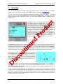
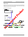
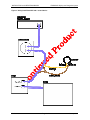
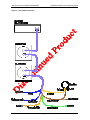
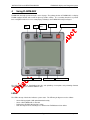
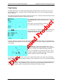
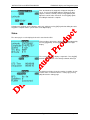
FLARM-NAV
INSTALLATION and OPERATING
MANUAL
FLARM-NAV Situation Awareness and
Navigation Display
Status
FLARM-NAV Software Version 1.00 (September, 2007)
© Swift Avionics P/L
INSTALLATION and OPERATING MANUAL
FLARM-NAV Display and Navigation System
Version Control
1.0
Initial release
1.1.0
Incorporated documentation for user interface and basic functionality
1.1.1
User interface updates
1.1.2
Audio connectors, boot loader details
1.1.3
Wiring diagrams added, typos fixed
Version 1.13
Page 2 of 25
January 2012
INSTALLATION and OPERATING MANUAL
1
FLARM-NAV Display and Navigation System
Welcome
Thank you for purchasing FLARM-NAV, a modern low-cost FLARM target display and basic navigation unit
for sailplanes and light aircraft. The main task for FLARM-NAV is to support the pilot, while the pilot scans
the airspace ahead with his own eyes. FLARM-NAV is simple to use and does not distract the pilot from the
main responsibility in hand.
Sport flying is an activity that is associated with considerable risks for crew, passengers, third parties and
other objects. In order to make full and safe use of FLARM-NAV, it is absolutely essential to be fully
aware of the risks, operating conditions, restrictions and limitations associated with the use of
FLARM-NAV. This includes familiarity with and observance of this Installation and User Manual.
We always welcome suggestions for the improvement of FLARM-NAV.
The latest version of this handbook and other related documents can be found at the website
http://www.rf-developments.com/. This website also has answers to Frequently Asked Questions.
The website also carries announcements when new software versions or functions are available. If you enter
your name on the mailing list, you will automatically receive notification of changes as and when they
happen: [email protected]
This unit is designed to operate with a FLARM compatible system. It has been tested on OzFLARM,
MiniOz, FLARM and LX FLARM. All these devices require regular software updates which are
available via the www.flarm.com website. These units will cease to function after February 2008 and
will require the mandatory software update
Version 1.13
Page 3 of 25
January 2012
INSTALLATION and OPERATING MANUAL
2
FLARM-NAV Display and Navigation System
Overview
First, we are assuming you are familiar with the FLARM system of collision awareness and alerting.
References to its operation are available on the RF Developments website or at www.flarm.com
Note: This system is by design completely compatible with FLARM devices from Europe. If travelling
overseas, make sure you’re the FLARM device that is connected to FLARM-NAV is operating on the correct
frequency and baud rate. Changing frequencies is done using FLARMtool which is available from the
FLARM website.
FLARM-NAV receives position and movement information from
an externally connected FLARM device, we will refer to our
OzFLARM or MiniOz as a FLARM compatible device from now
on. This information in the form of proprietary NMEA sentences
is decoded and displayed on the LCD display. Additionally any
alarms that might be generated from OzFLARM or MiniOz are
presented audibly via the FLARM-NAV speaker as well as
visually on the LCD and the superb bright LED. Additional to
FLARM information being displayed the FLARM-NAV will also
display basic navigation information. The user can upload via
the USB port and using a USB flash stick turnpoints for a
particular site and use these to navigate to. Additionally user
entered waypoints via the FLARM-NAV keys can be used.
If FLARM-NAV determines the risk of dangerous proximity to one or more aircraft or ground obstructions, the
unit gives the pilot warning of the greatest danger at that moment. The warning is given by a tone (as
described later in this document), The relative direction of the targets will be displayed on the FLARM-NAV
LCD with ONLY the alarmed target is displayed. Additionally a bright RED flashing LED will flash indicating
an alarm warning (in case the speaker volume is turned down or a fault has developed in the speaker).
Alarmed targets will reset after the threat has ceased or when
the pilot depresses the red acknowledge button. The pilot can
silence audible alarms for a period of 5 minutes if the red ESC
button is depressed for 3 seconds. This is mainly used when in
gaggle flights where multiple alarms may be received but are
not a “real” threat. Only use this option if you are sure you can
see the offending targets.
The operating range is very dependent upon the antenna installation in the aircraft. The normal range is
about 2 to 3 kms (unless privacy flag is set, which then hard limits displayed aircraft to <1.2km’s), but up to 5
km may be achieved in individual cases such as ground stations ( use of external high gain antennas, see
options on RF Developments website).
A great convenience of the unit, other than its main purpose, is the USB support for uploading new firmware
or turnpoints and for downloading IGC (non approved) files as backup or if the second port is used for
connection to a third party logger such as the Cambridge 20/25 black boxes (with after-market FLARM-NAV
firmware). This makes it very versatile and fills a gap when it comes to ease of operation, there is no need to
carry your laptop to the unit any more!
Version 1.13
Page 4 of 25
January 2012
INSTALLATION and OPERATING MANUAL
3
FLARM-NAV Display and Navigation System
Installation
General notes on installation
Installation and operation must be on the basis of non-interference with and no hazard to the existing suite of
other certified equipment necessary for safe flying operation, or installed to comply with official requirements.
Installation and operation must comply with official regulations and requirements. When FLARM-NAV is
permanently installed in an aircraft, the installation must comply with the 'Installation Policy' published by the
Australian Civil Aviation and Safety Authority (CASA), or the local agency in the country of operation.
FLARM-NAV should be mounted high up in an instrument panel in line with the pilots normally field of scan.
FLARM-NAV must not obstruct the piloting operation and in particular it must not hinder his field of view (do
not mount on top of the panel, additionally heat will also damage the unit). FLARM-NAV is not suited for use
in conjunction with night vision systems or night flying (no dimmers).
Location of the external speaker can be under the instrument panel hood or lip or behind the instrument
panel by drilling a small 3mm hole and gluing the speaker behind it thus allowing the audio to be heard.
As the unit fits a standard 57mm (2-1/4”) instrument hole, installation is simple, using the supplied drilling
information contained in this manual. The FLARM-NAV is inserted from the front and attached from the rear
via four securing screw posts.
If possible, FLARM-NAV should be so installed that the pilot will not inadvertently touch the push button
during cockpit ingress and egress.
Cables must not be folded or be under tension. The installation must allow adequate space for cable
connectors.
FLARM-NAV, the external FLARM device and radio antenna and the GPS antenna (optional – used for
MiniOz) should each be installed at least 10 cm away from the magnetic compass.
After installation, an appropriate entry should be made in the aircraft technical logs as to reflect an
installation performed under a “no interference, no hazard basis” as is the case for glide computers and PDA
displays, as well as other GPS devices. You as the installer must observe this rule. Additional tests under a
no interference basis might include the operation of the radio and a check that FLARM-NAV causes no
interference to its normal operation. Checks that other aircraft systems do not interfere with FLARM-NAV are
also needed. The best method is to fly with a friend at a distance around 2 kms, make sure all systems are
off ( i.e, other GPS, vario and glide computer), observe his lit target LED and maintain that distance. Turn on
each piece of equipment and note any change. Acceptable operation is one that is not affected by other
devices. Should a problem occur then consult our FAQ page.
Housing
Version 1.13
Page 5 of 25
January 2012
INSTALLATION and OPERATING MANUAL
FLARM-NAV Display and Navigation System
The ABS polycarbonate plastic housing is black to minimise glare and has been tested at temperatures from
-10 to +60 °C. Efforts should be made to prevent exposure to excessive direct or indirect solar heating. Even
if not subject to mechanical stress, the housing may be deformed at temperatures upwards of +84 °C, and
can also be deformed at lower temperatures in the presence of mechanical stress. The unit should not be
exposed to strong locally focused solar radiation, therefore care should be taken when the cockpit canopy is
left open.
Protruding rearwards are four 5/32” screw posts approximately 8mm long. It is important that when securing
the supplied cylinder nuts that you do not over tension them, a light firm hand pressure is sufficient. The two
communication ports (RJ45 sockets) are on the rear of the device.
The front LCD screen is glass and if cleaning is needed an alcohol based cleaner is recommended as well
as a soft cloth. Do not press hard against the screen as it may crack. Cracked screens will need replacing
and the unit will need to be returned for service.
Panel mounting
When drilling the holes please make sure the unit will not interfere with
adjacent instruments. Because the front covers the hole if there are small
drilling errors the unit will cover these up but try and avoid excessive over
sizing of the main hole.
Connectors
The rear of the display has two RJ45 8 pin
connectors. Port A is FLARM Data In and
receives the primary FLARM data. The second
port, Port B, is data out for connection to a
second display, for connection to a data logger,
or to a glide computer.
Port A
FLARM-NAV functions as a pass-through device,
such that data received at Port A is passed to
Port B and vice versa.
Port B
+12V
GND
Connector with Pin numbers,
tab down
Note. You can supply power to either port as they are identical with respect to power and ground, and there
is no risk of damaging the unit.
Version 1.13
Page 6 of 25
January 2012
INSTALLATION and OPERATING MANUAL
FLARM-NAV Display and Navigation System
Port A: FLARM Data In
The eight-pin RJ45 Power/Data socket accepts an eight-pin connector (if necessary, a six-pin connector)
that is locked in place. The pin connections are largely in-line with those set out in IGC GNSS FR
Specifications1, so that the same cables may be used both in the air and on the ground, as used for modern
IGC-compatible flight data recorders. The key to the connections is defined by the sequence from left to
2
right, not the numbering :
Port A (FLARM Data In) pin assignments
1.
2.
3.
4.
5.
6.
7.
8.
+6 to +26 VDC (recommended +12 VDC), linked with Pin 2 inside the unit
+6 to +26 VDC (recommended +12 VDC), linked with Pin 1 inside the unit
1 wire Dallas interface, for future expansion
GND, with Pin 7 and 8 linked to the unit
Rx In = FLARM transmits data and FLARM-NAV receives it.
Tx Out = FLARM Receives data and FLARM-NAV Transmits it.
GND ('negative'), linked with Pin 8 inside the unit
GND ('negative'), linked with Pin 7 inside the unit
FLARM-NAV is powered through either port but at least pins 1&2 and 7&8 must be connected. RS 232 data
is received at 19.2kb from the FLARM device, make sure the baud speed in FLARM is set to 19.2kb (default
in OzFLARM and MiniOz units).
When connecting from OzFLARM or MiniOz or other FLARM devices please ensure correct polarity of the
power and data wires. Your FLARM-NAV display is supplied with a pre wired loom, however, other FLARM
compatible devices might require different connections. If the power and ground are reversed there should
be no damage to the unit, it just will not work but has reverse protection. If power is applied to the RS 232
lines permanent damage will occur to this port.
Port B: FLARM Data Out
An 8-pole connector may be inserted in the 8-pole RJ45 socket on the bottom looking from the rear. The
connections to the pins are the same as for Pins 1 and 8 described above. This socket is intended for use by
third party applications like glide computers (e.g. Altair from Triadis Engineering, see www.rfdevelopments.com), by PDA’s or to a second FLARM-NAV in a two-seater configuration. This port basically
mimics the FLARM data coming in. If set to logger in the setup page then it will talk to a logger for
downloading IGC files etc.
Port B (FLARM data out) pin assignments
1.
2.
3.
4.
5.
6.
7.
8.
+6 to +26 VDC (recommended +12 VDC), linked with Pin 2 inside the unit
+6 to +26 VDC (recommended +12 VDC), linked with Pin 1 inside the unit
Speaker out +
GND, with Pin 7 and 8 linked inside the unit
Tx = transmits data
Rx = receives data
GND ('negative'), linked with Pin 8 inside the unit
GND ('negative'), linked with Pin 7 inside the unit
In normal configuration with OzFLARM, Pin 5 transmits the most important NMEA-0183 Version 2.0
compatible GPGGA and GPRMC codes at a fixed data rate of 19.2KB.
1
2
Chapter 2.7.2.2.7.2, www.fai.org/gliding/gnss/tech_spec_gnss.pdf
FLARM uses Pin-numbering in-line with IGC specifications. The usual numbering is in reverse order.
Version 1.13
Page 7 of 25
January 2012
INSTALLATION and OPERATING MANUAL
FLARM-NAV Display and Navigation System
Speaker output
Speaker audio is rated at 1 Watt into 4 Ohms, using an 8 Ohm speaker lowers the audio slightly. The
supplied speaker is suitable for most non-motorised installations. If using in a powered aircraft we suggest
feeding the audio via a splitter/combiner or using the aux input on a radio or intercom. Some level control
circuitry may be required such as an op amp or resistive divider.
Figure 1 Basic Flarm-NAV installation
Version 1.13
Page 8 of 25
January 2012
INSTALLATION and OPERATING MANUAL
FLARM-NAV Display and Navigation System
Figure 2 Driving both Flarm-NAV and a second device
Version 1.13
Page 9 of 25
January 2012
INSTALLATION and OPERATING MANUAL
FLARM-NAV Display and Navigation System
Figure 3 Optional connection to a flight recorder
Version 1.13
Page 10 of 25
January 2012
INSTALLATION and OPERATING MANUAL
FLARM-NAV Display and Navigation System
Figure 4 2 seat tandem coneection
Version 1.13
Page 11 of 25
January 2012
INSTALLATION and OPERATING MANUAL
4
FLARM-NAV Display and Navigation System
Using FLARM-NAV
FLARM-NAV basically operates through a series of pages. The primary function of FLARM-NAV is to display
FLARM-equipped aircraft and to alert the pilot of possible conflicts. The secondary function is to provide
basic navigation functions for cross-country flying. Following is the FLARM-NAV front panel layout.
FN
Cursor LEFT
OK
Cursor UP
Status
LED
USB Port
Cursor DOWN
ACK/ESC
Cursor RIGHT
The USB port is used for downloading IGC files and uploading of turn-points and performing firmware
updates. This port uses a standard USB flash stick.
LEDs
The LED at the top of the device indicates system status. The LED may be lit green or red as follows:
-
Green flashing: Signals USB upload/download activity
Green solid: FLARM traffic is detected
Red flashing: FLARM collision alert is active
Red solid: System error, including loss of GPS lock or FLARM transmission failure
Version 1.13
Page 12 of 25
January 2012
INSTALLATION and OPERATING MANUAL
FLARM-NAV Display and Navigation System
Sounds
A click sound is made when the user presses any button to give feedback.
A short beep is made when a new FLARM aircraft appears in range.
A repeating dit-dit tone is made for FLARM alert level 1.
A repeating long siren alarm is made for FLARM alert level 2.
A long beep is made when the aircraft is in sector (within one kilometer of the active waypoint).
Basic navigation through pages
There are 11 main pages. The default page is “Flight display”.
Press [LEFT] or [RIGHT] to move between pages.
Pressing [ESC] in any page returns to the “Flight display” page.
•
•
•
•
•
•
•
•
•
•
•
Task edit*
Waypoint edit+
Status
Mark point
Flight display
Current waypoint ^
Last waypoint ~
Waypoint list (alpha sorted) *
Waypoint list (distance sorted) *
Waypoint list (landpoints, distance sorted) *
Logger download+
* Displayed only if there are waypoints loaded
^ Displayed only if a task is defined
~ Displayed only if a temporary waypoint has been selected
+ Displayed only when not flying
Version 1.13
Page 13 of 25
January 2012
INSTALLATION and OPERATING MANUAL
FLARM-NAV Display and Navigation System
Flight display
The flight display page is the default page typically visible during the flight except when the user needs to
interact with the system. At any time, when a FLARM collision alert occurs, the system will automatically
return to this page.
This display has two modes, the first being a large three quarter size `radar’-like horizontal situation indicator
(HSI) with navigational information summarised on the left.
Pressing [OK] toggles between the display modes. Pressing
[Up]/[Down] adjusts the volume with a value from 1 to 7 being
displayed.
On the radar, an outer dashed ring is drawn at a range of 2.5
km, and inner ring is drawn at 1.0 km.
The second shows a smaller HIS with navigational information
summarised on the left. When there is no active task, the
navigational information is blank.
If a task is defined, a caret points to the active waypoint. When the aircraft is within 1 km of the waypoint, a
hollow triangle symbol appears in the top right corner of the radar area and pressing [Esc] will advance to the
next waypoint.
The FLARM traffic is drawn on the radar display as a disk,
hollow for FLARM alert level 0 (information), cross-hatched for
alert level 1 (caution), and solid for alert level 2 (warning).
If there is a height difference greater than 100 meters, above
the target is displayed a triangle pointing up or down with the
number of hundred of meters relative height.
For traffic with a collision alert level 1 and 2, a line is drawn from the traffic to the edge of the radar display.
At this edge, the relative altitude symbol is displayed. This design makes it easy to see in which direction the
traffic is relative to you.
Error status icons also may appear at the top right of the display. A small antenna symbol is displayed when
there is no valid GPS fix. The FLARM logo (a series of arcs) is displayed to indicate FLARM transmission
failure. A hollow battery symbol is displayed when FLARM reports low battery voltage.
Version 1.13
Page 14 of 25
January 2012
INSTALLATION and OPERATING MANUAL
FLARM-NAV Display and Navigation System
Task edit
The Task Edit page is used to view the active task, clear the task, or change the waypoints that make up the
active task.
On entry to the task page, the active task can be viewed. Next
to each waypoint is the range and bearing from the previous
waypoint. Pressing [OK] clears the task, and [ESC] returns to
the flight display. Pressing [Down] from here places a cursor
on the start point, in order to allow editing.
When the cursor is active, the currently selected waypoint
number is displayed in reverse colors. Pressing [Up]/[Down]
moves the cursor between items in the list. Pressing [ESC]
returns to the flight display. Pressing [OK] allows the current
waypoint number to be edited.
If the cursor is moved to the bottom of the list, however many
waypoints are in the task list, then the cursor will display “(add
wpt)”; here pressing [OK] will allow the waypoint to be selected
to add to the list.
When either a new waypoint is added or an existing waypoint is
edited, the waypoint select page is displayed. Here, pressing
[Up]/[Down] moves between waypoints in the database, and
[OK] selects the displayed waypoint for the task.
Version 1.13
Page 15 of 25
January 2012
INSTALLATION and OPERATING MANUAL
FLARM-NAV Display and Navigation System
Waypoint edit
The Waypoint Edit page is used to edit or add waypoints to the database. This page is automatically
skipped if the aircraft is moving faster than 10 km/h.
On entry to the waypoint edit page, the number of waypoints is
displayed. Pressing [OK] confirms that waypoints are to be
edited and [ESC] returns to the main page.
The waypoint edit method page allows the user to select which
method is to be used to edit waypoints. Pressing [Left] creates
a new waypoint, [Right] displays a waypoint selection list from
which a waypoint may be edited (if there are waypoints in the
database). Pressing [OK] uploads waypoints from the USB
key, and pressing [ESC] exits to the main page.
To load waypoints from USB, the waypoint file must be named “FLARMnav.dat” in the root directory of the
USB stick. A maximum of 1024 waypoints can be stored in the database.
Creating a new waypoint requires the user to press [OK] to
confirm, or [ESC] to return to the main page.
Editing a waypoint from the selection list displays a waypoint
and by pressing [Up]/[Down] the user can move between all
items in the waypoint database. Pressing [OK] will edit the
currently displayed waypoint. Pressing [ESC] returns to the
main page, and pressing [Left] returns to the waypoint edit
method page.
Editing an existing waypoint or creating a new waypoint uses
the same method. First, the name of the waypoint is displayed
along with a character cursor. Pressing [Left]/[Right] moves
the cursor left/right; pressing [Up]/[Down] adjusts the letter or
digit at the cursor position, and pressing [OK] signals that
editing of the name is complete.
Version 1.13
Page 16 of 25
January 2012
INSTALLATION and OPERATING MANUAL
FLARM-NAV Display and Navigation System
Next, the latitude of the waypoint is displayed along with a
cursor. Pressing [Left]/[Right] will move between the items
(degrees, minutes, seconds), and pressing [Up/Down] will
adjust the numeric value of the item. Pressing [OK] signals
that editing the latitude is complete.
Following this, longitude can be edited the same way, and then pressing [OK] signals that editing the entire
waypoint is complete and the system returns to the flight display.
Status
The status page is used to display the aircraft’s state from the GPS.
There are three status pages, which may be cycled through by
pressing [Up]/[Down]. Pressing [ESC] returns to the flight
display.
The second status page displays a stopwatch. Pressing [OK]
activates the stopwatch, or it is already activated, will stop it.
The third status display shows the number of satellites in view
and the status of connected devices. In this page, pressing
[OK] will enter the settings page.
Version 1.13
Page 17 of 25
January 2012
INSTALLATION and OPERATING MANUAL
FLARM-NAV Display and Navigation System
Settings
The settings page allows the FLARM-NAV configuration to be set up. There are several configurable
settings.
Pressing [ESC] will return to the flight display without saving
changes. To edit an item, press [Up/Down] to adjust the value.
Pressing [OK] signals editing the current item is complete and
the next setting item will be displayed for editing.
Once editing or review of all items is complete, the system saves the settings to nonvolatile memory and
returns to the flight display.
The configuration settings are:
• Device A type
• Device A baud rate
• Device B type
• Device B baud rate
• Distance units
• Speed units
• Altitude/height units
• Volume
(FLARM or Generic GPS)
(1200 to 57600)
(Pass-through or None)
(1200 to 57600)
(km or nmi)
(kph or knots)
(ft or m)
(0 to 8)
Mark point
The mark point page is used to generate temporary marks at the current GPS location, in order to mark
points of interest (e.g. thermal locations). Upon entering the mark point page, a list of options is presented.
Pressing [OK] marks the current location. Pressing [ESC]
returns to the flight display. Pressing [Up]/[Down] selects
previous marks in case the pilot wants to navigate back to the
mark location (if marks have previously been created).
When a previously marked point is selected, the distance and
relative bearing to the mark is displayed and updated
continuously.
Version 1.13
Page 18 of 25
January 2012
INSTALLATION and OPERATING MANUAL
FLARM-NAV Display and Navigation System
Current waypoint
The current waypoint page shows detailed information on the current waypoint, the total task length, and
distance remaining. This page is skipped automatically if there is no active task.
Pressing [Up]/[Down] will cycle between the waypoints in the
task. Pressing [OK] will select that waypoint as the active one
and returns to the flight display. Pressing [ESC] returns to the
flight display.
Last waypoint
The last waypoint page shows the previous waypoint in the task if it was temporarily adjusted via the
waypoint list pages (described below in this document). If no temporary waypoint was selected, this page is
skipped automatically.
Otherwise, pressing [OK] restores the waypoint and returns to
the main page. Pressing [ESC] returns to the main page.
Waypoint lists
There are three waypoint list pages, the first displays the waypoints in alphabetical order, the second
displays waypoints in increasing order of distance, and the third displays landpoints in increasing order of
distance. Next to each item is the range in km and relative bearing of the waypoint.
In each of these pages, pressing [ESC] returns to the flight
display.
Pressing [Up]/[Down] moves the cursor in the list. Pressing
[OK] selects the waypoint as a temporary replacement of the
waypoint in the task.
Version 1.13
Page 19 of 25
January 2012
INSTALLATION and OPERATING MANUAL
FLARM-NAV Display and Navigation System
Logger download
The logger download page allows IGC logs to be retrieved from the FLARM device. Note that the FLARM
must be configured to enable IGC logging and have the pilot name, aircraft ID and class entered.
To download logs, insert a USB memory stick in the slot at the
top of the FLARM-NAV device and press [OK]. The files are
displayed while downloading and the LED flashes during
download. The device downloads the most recent flight log.
After the download is complete, pressing [OK] will then
download the previous flight log etc. Files are not over-written,
and are not deleted from the FLARM memory.
Pressing [FN] reboots the device.
Please Note – From pressing O.K to actually downloading the file it could take up to 5 seconds to start this
procedure, be patient. Also to download the file could take up to 5 minutes depending on the settings in the
flarm device as to logging intervals, shorter intervals create big files. If the LED is blinking then it is
downloading.
Version 1.13
Page 20 of 25
January 2012
INSTALLATION and OPERATING MANUAL
5
FLARM-NAV Display and Navigation System
Firmware updates ( Not Waypoint uploads )
****Warning***** The following procedure relates to program updates – NOT
WAYPOINT FILE UPDATES OR LOGGER DOWNLOADS!!!!!
The FLARM-NAV firmware can be updated via USB stick.
1. Copy the supplied FLARM-NAV image file to the USB stick. The file name must be `flarmnav.bin’.
2. Ensure battery is fully charged.
3. Disconnect power to the FLARM-NAV
4. Insert the USB stick into the FLARM-NAV slot
5. Hold down the [OK] button for at least 2 seconds while turning on the device
6. The LED will turn red and then flash (after about 5 seconds) approximately once per second for a
few minutes.
7. Once the system has completed the upload the LED will go out.
8. The system will then reboot. If the system fails to start, or if the update process was interrupted,
repeat the process again from step 3. If after this try the system does not reboot, contact support.
9. Check the configuration settings are correct. Some firmware updates may require the device to be
re-configured and turnpoint files to be re loaded.
Version 1.13
Page 21 of 25
January 2012
INSTALLATION and OPERATING MANUAL
6
FLARM-NAV Display and Navigation System
Limitations
FLARM and FLARM-NAV are designed and built as a non-essential situation awareness only unit to support
the pilot, and cannot always provide reliable warnings. In particular, FLARM-NAV does not give any
guidance on avoiding action. Under no circumstances should a pilot or crewmember adopt different tactics or
deviate from the normal principles of safe airmanship. The use of FLARM-NAV is solely at the discretion of
the commander and his crew. Operation must be preceded by thorough familiarisation by the commander or
his delegated crewmember with the Operating Manual.
FLARM-NAV can only warn the pilot of the presence of other aircraft that are also fitted with FLARM-NAV or
compatible equipment, or warn of obstructions that are stored in the internal data bank. FLARM-NAV does
not communicate with Mode A/C/S transponders, and remains undetected by ACAS/TCAS/TPAS or Air
Traffic Control systems. Likewise, FLARM-NAV does not communicate with TIS-B, FIS-B or ADS-B.
The use of FLARM-NAV is at the sole responsibility and discretion of the aircraft commander or his
delegated crewmember. Operation must be preceded by full familiarisation with the equipment and careful
study of the Operating Manual.
At present FLARM-NAV is not certified by the Civil Aviation Authorities and has not been tested in
accordance with the normal aviation requirements (e.g. DO-160E). The FLARM software development is
commensurate with Level E of DO-178B; in other words a failure of the unit will have no effect upon aircraft
operation and does not increase crew workload. The FLARM-NAV obstruction data bank is not certified.
Air band radio frequency allocation and licensing conditions may vary from country to country. The aircraft
commander is solely responsible for ensuring that FLARM-NAV is operated in conformity with the respective
licensing conditions. No licence is required to operate FLARM-NAV in Australia.
Until further notice FLARM-NAV may not be used in the USA or Canada without written authority of FLARM
Technology, or in aircraft that is registered and/or insured in the USA or Canada. Likewise, operation of
FLARM is forbidden in aircraft in which one or more of the occupants resides in or is a citizen of the USA or
Canada. Likewise, use of FLARM is forbidden if the aircraft concerned takes off from, makes an intermediate
or final landing in the USA or Canada.
RF Developments, its associates, development team, suppliers, manufacturers and data suppliers accept no
responsibility for any damage or claims that may arise from use of FLARM-NAV.
Version 1.13
Page 22 of 25
January 2012
INSTALLATION and OPERATING MANUAL
7
FLARM-NAV Display and Navigation System
Technical Data
The following data are provided without guarantee and may be altered at any time without notice.
Dimensions:
Length:
Weight:
Power supply:
Power drain:
Serial data:
Temperature:
Vibration:
Country of Origin:
Version 1.13
67 mm x 67mm housing front area with 15mm depth to front of instrument panel
Designed to fit a 57mm (2 ¼) instrument hole
Overall length is 35mm
Length extruding from rear (mounted in panel) is 20mm
155 g
external power supply 6.0 to 28.0 (peak voltage up to30.0) VDC via RJ45,
recommended value 12 VDC;
direct galvanic link to aircraft battery via an obligatory 500 mA circuit breaker,
separated from essential aircraft systems;
FLARM-NAV has a reverse polarity protection
typically approx. 55 mA at 12 VDC, approx. 37 mA at 24 VDC
(normal operation without warnings or external display),
a collision warning may double these values
bi-directional RS232, compatible with NMEA-0183 Version 2.0, standard message
format 19.2kBaud, additional NMEA proprietary sentences PFLA and PGRMZ
(described in a separate document)
Operation: -10 to +60 °C, storage: -20 to +70 °C,
no certification in accordance with DO-160E Sections 4 and 5
Use in conditions of strong vibration or turbulence should be avoided or subsequently
checked prior to continued operation,
no certification in accordance with DO-160E Section 8
Australia
Page 23 of 25
DECLARATION OF CONFORMITY
Complies with AS/NZS 4268:2003
Low power transmitting and receiving
device.
RF Developments N-15142
ABN 60 789 837 451
This device must be operated in
accordance with the manufacturers
recommended installation and users
guide. Under no circumstances should
this equipment be modified.
Modifications will render the unit un
approved and removes all warranties.
January 2012
INSTALLATION and OPERATING MANUAL
FLARM-NAV Display and Navigation System
Appendix A: Quick reference card
Version 1.13
Page 24 of 25
January 2012
INSTALLATION and OPERATING MANUAL
FLARM-NAV Display and Navigation System
Remember, FLARM-NAV is an aid to situation awareness, others must
be equipped with compatable FLARM/FLARM-NAV units – so spread the
word!
You must continue to use good lookout and fly safely.
Version 1.13
Page 25 of 25
January 2012