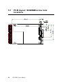
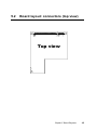
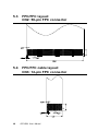
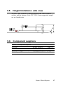
1
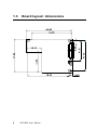
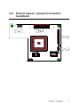
CPC-2520
VGA/LCD module for Mini Biscuit PC
User’s Manual
Copyright notice
This document is copyrighted, October 1999. All rights are
reserved. The original manufacturer reserves the right to make
improvements to the products described in this manual at any time
without notice.
No part of this manual may be reproduced, copied, translated or
transmitted in any form or by any means without the prior written
permission of the original manufacturer. Information provided in
this manual is intended to be accurate and reliable. However, the
original manufacturer assumes no responsibility for its use, nor for
any infringements upon the rights of third parties which may result
from its use.
Acknowledgements
AMI is a trademark of American Megatrends, Inc.
Cyrix is a trademark of Cyrix Corporation.
IBM, PC/AT, PS/2 and VGA are trademarks of International
Business Machines Corporation.
Intel and Pentium are trademarks of Intel Corporation.
Microsoft Windows and MS-DOS are registered trademarks of
Microsoft Corp.
C&T is a trademark of Chips and Technologies, Inc.
All other product names or trademarks are properties of their
respective owners.
Part No. 2006252000
1st Edition Printed in Taiwan October 1999
Product warranty
Advantech warrants to you, the original purchaser, that each of its
products will be free from defects in materials and workmanship
for one year from the date of purchase.
This warranty does not apply to any products that have been
repaired or altered by persons other than repair personnel authorized by Advantech, or which have been subject to misuse, abuse,
accident or improper installation. Advantech assumes no liability
under the terms of this warranty as a consequence of such events.
Because of Advantech high quality-control standards and rigorous
testing, most of our customers never need to use our repair service.
If an Advantech product is defective, it will be repaired or replaced at no charge during the warranty period. For out-ofwarranty repairs, you will be billed according to the cost of
replacement materials, service time and freight. Please consult
your dealer for more details. If you think you have a defective
product, follow these steps:
1. Collect all the information about the problem encountered.
(For example, CPU speed, Advantech products used, other
hardware and software used, etc.) Note anything abnormal and
list any on- screen messages you get when the problem occurs.
2. Call your dealer and describe the problem. Please have your
manual, product, and any helpful information readily available.
3. If your product is diagnosed as defective, obtain an RMA
(return merchandize authorization) number from your dealer.
This allows us to process your return more quickly.
4. Carefully pack the defective product, a fully-completed Repair
and Replacement Order Card and a photocopy proof of
purchase date (such as your sales receipt) in a shippable
container. A product returned without proof of the purchase
date is not eligible for warranty service.
5. Write the RMA number visibly on the outside of the package
and ship it prepaid to your dealer.
Packing list
Before installing your board, make sure that the following materials have been received:
• 1 CPC-2520 VGA/LCD module for mini biscuit PC
• 2 floppy disks (or one CD-ROM) including SVGA utility
programs and drivers for Windows 95/98/NT
• 1 warranty certificate
• This user's manual
If any of these items are missing or damaged, contact your
distributor or sales representative immediately.
Technical support and sales assistance
If you have any technical questions about the CPC-2520 or any
other Advantech products, please visit our support website at:
http://support.advantech.com.tw
For more information about Advantech's products and sales
information, please visit:
http://www.advantech.com
Contents
Chapter 1 General Information ................................. 1
1.1
1.2
1.3
Introduction .................................................................. 2
Specifications ................................................................ 3
General ........................................................................... 3
Mechanical and environmental ...................................... 3
Board layout: dimensions ............................................ 4
Chapter 2 Installation ................................................ 5
2.1
2.2
2.3
2.4
2.5
2.6
2.7
2.8
2.9
Jumpers and connectors .............................................. 6
Board layout: jumper/connector locations ................ 7
Safety precautions ........................................................ 8
Jumper settings ............................................................ 9
LCD Panel select (SW1) ............................................ 10
Display connectors (CN2, CN3) ................................ 10
LCD display connector (CN2) ................................... 11
VGA display connector (CN3) .................................. 12
FPC cable installation ................................................ 14
Chapter 3 Software Configuration ......................... 15
3.1
3.2
Introduction ................................................................ 16
Connections for five standard LCDs ........................ 16
Connections to Sharp LM64183P, LM64P89
(640 x 480 DSTN MONO LCD) ............................... 16
Connections to Toshiba LTM10C042
(640 x 480 TFT color LCD) ....................................... 18
Connections to Sharp LM64C142
(640 x 480 DSTN color LCD) ................................... 19
Connections to Toshiba LTM12C275A
(800 x 600 TFT color LCD) ....................................... 20
Chapter 4 PCI SVGA Setup ..................................... 21
4.1
4.2
4.3
Introduction ................................................................ 22
4.1.1 Chipset ................................................................ 22
4.1.2 Display memory .................................................. 22
4.1.3 Display types ....................................................... 22
Installation of SVGA driver ...................................... 23
4.2.1 Installation for Windows 3.1 .............................. 24
4.2.2 Installation for Windows 95 ............................... 26
4.2.3 Installation for Windows NT .............................. 29
Further information................................................... 32
Chapter 5 Board Diagrams ..................................... 33
5.1
5.2
5.3
5.4
5.5
5.6
PCB layout: SODIMM/screw hole locations ...........
Board layout: connectors (top view) ........................
FPC/FFC layout: CN2: 50-pin FPC connector .......
FPC/FFC cable layout:
CN3: 12-pin FPC connector ......................................
Height limitations: side view .....................................
Component suppliers .................................................
34
35
36
36
37
37
Tables
Table 2-1: Jumpers and connectors .......................................................... 6
Table 2-2: LCD display connector (CN2) ................................................. 11
Table 2-3: VGA display connector (CN3) ................................................ 12
Table 2-4: VGA display connector (CN3) ................................................ 13
Table 3-1: Connections to Sharp LM64183P, LM64P89 ......................... 16
Table 3-2: Connections to PLANAR EL ................................................... 17
Table 3-3: Connections to Toshiba LTM10C042 ..................................... 18
Table 3-4: Connections to Sharp LM64C142 .......................................... 19
Table 3-5: Connections to Toshiba LTM12C275A .................................. 20
Table 5-1: Component suppliers .............................................................. 37
CHAPTER
1
General Information
This chapter provides background
information for the CPC-2520. Sections
include:
• Card specifications
• Board layout
1.1
Introduction
The CPC-2520 is an extension VGA/LCD module for the
CPC-2245 mini biscuit PC. The CPC-2520 uses a C&T 69000
chipset for its PCI/SVGA controller. It supports many popular
LCD, EL, and gas plasma flat panel displays and conventional
analog CRT monitors. The 69000 VGA BIOS supports monochrome LCD, EL, color TFT and STN LCD flat panel displays. In
addition, it also supports interlaced and non-interlaced analog
monitors (color and mono-chrome VGA) in high-resolution modes
while maintaining complete IBM VGA compatibility. Digital
monitors (i.e. MDA, CGA, and EGA) are NOT supported.
Multiple frequency (multi-sync) monitors are handled as if they
were analog monitors.
With on-board 2 MB display memory, the VGA controller can
drive CRT displays or color panel displays with resolutions up to
1024 x 768 at 64 K colors.
CRT and panel displays can be used simultaneously. The
CPC-2520 can be set in one of three configurations: on a CRT, on
a flat panel display, or on both simultaneously. The system is
initially set to simultaneous display mode.
2
CPC-2520 User's Manual
1.2
Specifications
General
• Flat panel VGA interface
• Chipset: C&T 69000 VGA controller with Windows accelerator
• Display memory: 2 MB SDRAM in built-in chip
• Display output:
50-pin FPC connector for flat panel interface
12-pin FPC connector for VGA interface
• Display type: Supports CRT and flat panel (TFT, DSTN, and
mono) displays. Can display both CRT and flat panel simultaneously
• Resolution: 640 x 480 @ 16 M colors
800 x 600 @ 16 M colors
1024 x 768 @ 64 K colors
Mechanical and environmental
• Power supply voltage: +5 V (4.75 V ~ 5.25 V)
• Max. power requirements: +5 V @ 0.8 A
• Operating temperature: 0 ~ 60° C (32 ~ 140° F)
• Board size: 68 x 100 mm (2.7" x 3.9")
• Weight: 0.05 kg (0.11 lb)
Chapter 1 General Information
3
1.3
4
Board layout: dimensions
CPC-2520 User's Manual
CHAPTER
2
Installation
This chapter explains the setup procedures of CPC-2520 hardware, including
instructions on setting jumpers andconnecting peripherals, switches andindicators. Be sure to read all safety precautions
before you begin the installation procedure.
2.1
Jumpers and connectors
On-board connectors link to external devices such as hard disk
drives, keyboards, or floppy drives, etc. In addition, the board has
jumpers for configuring your board for specific applications.
The table below lists the function of each of the board's jumpers
and connectors. Later sections in this chapter give detailed
information on each jumper setting, and gives instructions for
connecting external devices to your card.
Table 2-1: Jumpers and connectors
Number
SW1
CN1
CN2
CN3
CN4
6
Function
LCD panel type setting
Reserved for VGA testing
LCD display connector
VGA display connector
PCI bus
CPC-2520 User's Manual
2.2
Board layout: jumper/connector
locations
Chapter 2 Installation
7
2.3
8
Safety precautions
Warning!
Always completely disconnect the power cord
from your chassis whenever you are working on
it. Do not make connections while the power is on
because sensitive electronic components can be
damaged by the sudden rush of power. Only
experienced electronics personnel should open
the PC chassis.
Caution!
Always ground yourself to remove any static
charge before touching the CPU card. Modern
electronic devices are very sensitive to static
electric charges. Use a grounding wrist strap at
all times. Place all electronic components on a
static-dissipative surface or in a static-shielded
bag when they are not in the chassis.
CPC-2520 User's Manual
2.4
Jumper settings
You configure your card to match the needs of your application by
setting jumpers. A jumper is the simplest kind of electric switch. It
consists of two metal pins and a small metal clip (often protected
by a plastic cover) that slides over the pins to connect them. To
close a jumper you connect the pins with the clip. To open a
jumper you remove the clip. Sometimes a jumper will have three
pins, labeled 1, 2 and 3. In this case you would connect either pins
1 and 2 or 2 and 3.
1
Open
Closed
2
Closed 2-3
A pair of needle-nose pliers may be helpful when working with
jumpers. If you have any doubts about the best hardware configuration for your application, contact your local distributor or sales
representatives before you make any changes.
Chapter 2 Installation
9
2.5
LCD panel select (SW1)
Panel #
1
2
3
4
5
6
7
8
9
10
11
12
13
14
15
16
2.6
SW1
Panel Type
A
B
C
D
ON
ON
ON
ON
1024 x 768 DSTN
OFF
ON
ON
ON
1280 x 1024 TFT
ON
OFF
ON
ON
640 x 480 DSTN
OFF
OFF
ON
ON
800 x 600 DST
ON
ON
OFF
ON
640 x 480 Sharp TFT
OFF
ON
OFF
ON
640 x 480 18-bit TFT
ON
OFF
OFF
ON
1024 x 768 36-bit TFT
OFF
OFF
OFF
ON
800 x 600 TFT
ON
ON
ON
OFF
800 x 600 TFT (large BIOS only)
OFF
ON
ON
OFF
800 x 600 TFT (large BIOS only)
ON
OFF
ON
OFF
800 x 600 DSTN (large BIOS only)
OFF
OFF
ON
OFF
800 x 600 DSTN (large BIOS only)
ON
ON
OFF
OFF
1024 x 768 TFT (large BIOS only)
OFF
ON
OFF
OFF
1280 x 1024 DSTN (large BIOS only)
ON
OFF
OFF
OFF
1024 x 600 DSTN (large BIOS only)
OFF
OFF
OFF
OFF
1024 x 600 TFT (large BIOS only)
Display connectors (CN2, CN3)
The CPC-2520 PCI SVGA interface can drive conventional CRT
display and is capable of driving a wide range of flat display,
including electroluminescent (EL), gas plasma, passive LCD, and
active LCD displays. The card has two connectors to support these
display, one for CRT VGA monitor and one for flat panel displays.
10
CPC-2520 User's Manual
2.7
LCD display connector (CN2)
LCD display connector on CPC-2520 is a 50-pin FPC connector. The
CPC-2520 supports up to 36 bits LCD panel.
Table 2-2: LCD display connector (CN2)
Pin
1
2
3
4
5
6
7
8
9
10
11
12
13
14
15
16
17
18
19
20
21
22
23
24
25
Note:
Signal
ENAVEE
LP
ENAVDD
FLM
SHIFT CLK
SHIFT CLKM
ENABKL
GND
P0
P1
P2
P3
P4
P5
P6
P7
GND
P8
P9
P10
P11
P12
P13
P14
Pin
26
27
28
29
30
31
32
33
34
35
36
37
38
39
40
41
42
43
44
45
46
47
48
49
50
Signal
P15
P16
P17
P18
P19
GND
P20
P21
P22
P23
P24
P25
P26
P27
GND
P28
P29
P30
P31
P32
P33
P34
P35
GND
GND
The model number of the CN2 socket is
IL-FPR-50S-HF (JAE Co., Ltd.)
Chapter 2 Installation
11
2.8
VGA display connector (CN3)
VGA display connector on CPC-2520 is a 12-pin FPC connector,
these VGA signals can be connected to client's system board
through a FPC cable. Client can design this cable by referring to
Cable layout diagram in chapter of design guide.
Table 2-3: VGA display connector (CN3)
Pin
1
2
3
4
5
6
7
8
9
10
11
12
Note:
12
Signal
GND
+5V
+5V
GND
H SYNC
DDC1
V SYNC
DDC0
BLUE
RED
GREEN
GND
The model number of the CN3 socket is
IL-FPR-12S-HFC (JAE Co., Ltd.)
CPC-2520 User's Manual
The VGA connector is a 15-pin D-SUB connector. User can follow a
transfer table to layout these VGA signals to a standard 15-pin
D-SUB connector.
5
1
10
6
15
11
Table 2-4: VGA display connector (CN3)
VGA
Pin
1
2
3
4
5
6
7
8
Signal
RED
GREEN
BLUE
N/C
GND
GND
GND
GND
CN3
Pin
10
11
9
1
1
12
12
Signal
RED
GREEN
BLUE
GND
GND
GND
GND
VGA
Pin
9
10
11
12
13
14
15
Signal
Vcc
GND
N/C
SDT
H-SYNC
V-SYNC
SCK
CN3
Pin
2, 3
4
8
5
7
6
Signal
+V
GND
DDC0
H SYNC
V SYNC
DDC1
Chapter 2 Installation
13
2.9
14
FPC cable installation
CPC-2520 User's Manual
CHAPTER
3
Software Configuration
This chapter details the software configuration information. It shows you how to
configure the card to match your application requirements.
Sections include:
• Introduction
• Connections for five standard LCDs
3.1
Introduction
The CPC-2520 VGA BIOS are located in a 128 Kbyte, 32-pin (JEDEC
spec.) Flash ROM device, designated U1. To set different types of
LCD panels please choose Panel type from the DIP Switch.
3.2
Connections for five standard LCDs
Connections to Sharp LM64183P, LM64P89
(640 x 480 DSTN MONO LCD)
Table 3-1: Connections to Sharp LM64183P, LM64P89
LM64183/64P89
Pin
Name
CN1-1
S
CN1-2
CP1
CN1-3
CP2
CN1-4
DISP
CN1-5
VDD
CN1-6
VSS
CN1-7
VEE
CN1-8
DU0
CN1-9
DU1
CN1-10
DU2
CN1-11
DU3
CN1-12
DL0
CN1-13
DL1
CN1-14
DL2
CN1-15
DL3
* LM64183P -17 V
* LM64P89 -20 V
16
CPC-2520 User's Manual
CPC-2520 CN2
Pin
Name
4
FLM
2
LP
5
SHIFT CLK
External power (+5 V)
External power (+5 V)
18,31,40
GND
External power*
13
P3
12
P2
11
P1
10
P0
17
P7
16
P6
15
P5
14
P4
Connections to PLANAR EL (640 x 480 AD4 EL)
Table 3-2: Connections to PLANAR EL
PLANAR 640 x 480 AD4
Pin
Name
1
GND
2
DO
3
GND
4
D1
5
GND
6
D2
7
NC
8
D3
9
NC
10
D4
11
NC
12
D5
13
NC
14
D6
15
GND
16
D7
17
GND
18
VCLK
19
GND
20
/BLANK
21
GND
22
HS
23
NC
24
VS
25
NC
26
SELFTST
27
COLMAP
28
ENABLE
29
RESERVED
30
/LOWPOW
31,32
NC
33
RESERVED
34
NC
CPC-2520 CN2
Pin
Name
9
GND
23
P12
9
GND
24
P13
18
GND
25
P14
26
P15
19
P8
20
P9
21
P10
18
GND
22
P11
31
GND
6
SHIFT CLK31
GND
40
GND
7
M
4
FLM
40
GND
49
GND
-
Chapter 3 Software Configuration
17
Connections to Toshiba LTM10C042
(640 x 480 TFT color LCD)
Table 3-3: Connections to Toshiba LTM10C042
LTM10C042
Pin
Name
1
GND
2
CLK
3
GND
4
R0
5
R1
6
R2
7
GND
8
R3
9
R4
10
R5
11
GND
12
G0
13
G1
14
G2
15
GND
16
G3
17
G4
18
G5
19
GND
20
ENAB
21
GND
22
B0
23
B1
24
B2
25
GND
26
B3
27
B4
28
B5
29
GND
30
VDD
31, 32 VDD
18
CPC-2520 User's Manual
CPC-2520 CN2
Pin
Name
9
GND
5
SHIFT CLK
9
GND
29
P18
30
P19
32
P20
18
GND
33
P21
34
P22
35
P23
18
GND
21
P10
22
P11
23
P12
31
GND
24
P13
25
P14
26
P15
31
GND
7
M
40
GND
12
P2
13
P3
14
P4
40
GND
15
P5
16
P6
17
P7
49
GND
External power
External power
Connections to Sharp LM64C142
(640 x 480 DSTN color LCD)
Table 3-4: Connections to Sharp LM64C142
LM64C142
Pin
CN1-1
CN1-2
CN1-3
CN1-4
CN1-5
CN1-6
CN1-7
CN1-8
CN1-9
CN1-10
CN1-11
CN1-12
CN1-13
CN1-14
CN1-15
CN2-1
CN2-2
CN2-3
CN2-4
CN2-5
CN2-6
CN2-7
CN2-8
CN2-9
CN2-10
Name
YD
LP
XCX
DISP
VDD
VSS
VEE
DU0
DU1
DU2
DU3
DU4
DU5
DU6
DU7
VSS
DL0
DL1
DL2
DL3
DL4
DL5
DL6
DL7
VSS
CPC-2520 CN2
Pin
Name
4
FLM
2
LP
5
SHIFT CLK
External power (+5 V)
External power (+5 V)
9
GND
External power
22
P11
21
P10
20
P9
19
P8
13
P3
12
P2
11
P1
10
P0
18
GND
26
P15
25
P14
24
P13
23
P12
17
P7
16
P6
15
P5
14
P4
31
GND
Chapter 3 Software Configuration
19
Connections to Toshiba LTM12C275A
(800 x 600 TFT color LCD)
Table 3-5: Connections to Toshiba LTM12C275A
LTM12C275A
Pin
Name
1
GND
2
NCLK
3
NC
4
NC
5
GND
6
R0
7
R1
8
R2
9
R3
10
R4
11
R5
12
GND
13
G0
14
G1
15
G2
16
G3
17
G4
18
G5
19
GND
20
B0
21
B1
22
B2
23
B3
24
B4
25
B5
26
ENAB
27
GND
28
VCC
29
VCC
30
GND
20
CPC-2520 User's Manual
CPC-2520 CN2
Pin
Name
9
GND
5
SHIFT CLK
NC
NC
9
GND
29
P18
30
P19
32
P20
33
P21
34
P22
35
P23
18
GND
21
P10
22
P11
23
P12
24
P13
25
P14
26
P15
31
GND
12
P2
13
P3
14
P4
15
P5
16
P6
17
P7
7
M
40
GND
External power (+5 V)
External power (+5 V)
49
GND
CHAPTER
4
PCI SVGA Setup
• Introduction
• Installation of SVGA driver for
- Windows 3.1
- Windows 95
- Windows NT
• Further information
4.1
Introduction
The CPC-2520 has an on-board PCI flat panel/VGA interface. The
specifications and features are described as follows:
4.1.1 Chipset
The CPC-2520 uses a C&T 69000/69030 chipset for its
PCI/SVGA controller. It supports many popular LCD, EL, and gas
plasma flat panel displays and conventional analog CRT monitors.
The 69000/69030 VGA BIOS supports monochrome LCD, EL,
color TFT and STN LCD flat panel displays. In addition, it also
supports interlaced and non-interlaced analog monitors (color and
mono-chrome VGA) in high-resolution modes while maintaining
complete IBM VGA compatibility. Digital monitors (i.e. MDA,
CGA, and EGA) are NOT supported. Multiple frequency (multisync) monitors are handled as if they were analog monitors.
4.1.2 Display memory
With on-board 2 MB display memory, the VGA controller can
drive CRT displays or color panel displays with resolutions up to
1024 x 768 at 64 K colors. The display memory can be expanded
to 4 MB for true-color resolution of 1024 x 768 with C&T 69030.
4.1.3 Display types
CRT and panel displays can be used simultaneously. The
CPC-2520 can be set in one of three configurations: on a CRT, on
a flat panel display, or on both simultaneously. The system is
initially set to simultaneous display mode. The utility disks
includes three *.COM files in the subdirectory Utility\vga\ which
can be used to configure the display. In order to use these configuration programs, type the file name and path at the DOS prompt.
CT.COM: Enables CRT display only
FP.COM: Enables panel display only
SM.COM: Enables both displays simultaneously
22
CPC-2520 User's Manual
4.2
Installation of SVGA driver
Complete the following steps to install the SVGA driver. Follow
the procedures in the flow chart that apply to the operating system
that you are using within your CPC-2520.
Important: The following windows illustrations are examples
only. You must follow the flow chart instructions
and pay attention to the instructions which then
appear on your screen.
Note:
<Enter> means pressing the "Enter" key on the
keyboard.
Chapter 4 Award BIOS Setup
23
4.2.1 Installation for Windows 3.1
1.
a. Insert the utility
disk into the
floppy disk drive.
b. Select "File" in
Program Manager.
c. Click "Run" and
type: "A:\VGA\
Win31\Setup.exe".
2.
a. Choose the
language you want
to use during
installation.
3.
a. Select the
highlighted item.
b. Press "ENTER".
4.
a. Press "ENTER" to
install all
resolutions.
24
CPC-2520 User's Manual
D:\VGA\Win31\Setup.exe
5.
a. Type the path of
the operating
system.
6.
a. When installation
is completed,
reboot the system.
b. You will see the
"ChipsCPL" icon in
the control panel.
7.
ChipsCPL
a. Double click
"ChipsCPL".
b. Adjust screen size,
color and refresh
rate to your
preferences.
END
Chapter 4 Award BIOS Setup
25
4.2.2 Installation for Windows 95
1.
a. Select "Start",
"Settings",
"Control Panel",
"Display",
"Settings".
b. Press "Advanced
Properties".
2.
a. Choose the
"Adapter" label.
b. Press the
"Change..."
button.
3.
a. Press the "Have
Disk" button.
4.
a. Insert the utility
disk into the
floppy disk drive.
b. Type "A:\VGA\
Win95\Setup\exe".
c. Press "OK".
26
CPC-2520 User's Manual
D:\VGA\Win95\
5.
a. Select the
highlighted item.
b. Click the "OK"
button.
6.
a. C&T69000/69030
appears in the
adapter label.
b. Click the "Apply"
button.
7.
a. Press "Yes" to
reboot.
8.
a. Repeat Step 1 on
the previous page
of this manual.
The "CHIPS"
label appears in
"Display".
b. Adjust resolution
and color.
69000
Chapter 4 Award BIOS Setup
27
a. Click the "CHIPS"
label.
b. Adjust the refresh
rate and display[7]
type.
c. Press "OK" to
exit.
9.
10.
a. Press "Yes" to
set the monitor
type.
11.
a. Select
"Standard",
"Super VGA 800
x 600", or "XGA".
b. Press the "OK"
button.
12.
a. Choose "Restart"
to reboot.
END
28
CPC-2520 User's Manual
4.2.3 Installation for Windows NT
1.
a. Select "Start", "Settings",
"Control Panel".
b. Double click the "Display"
icon.
2.
a. Choose the "Settings" label.
b. Press the "Display Type"
button.
3.
a. Press the "Change..." button.
4.
a. Click the "Have Disk..."
button.
Chapter 4 Award BIOS Setup
29
a. Insert the utility disc into
the floppy disk drive.
b. Type "A:\VGA\NT40\" in
the blank.
c. Press the "OK" button.
5.
D:\VGA\NT40\
6.
a. Select the highlighted
item.
b. Press the "OK" button.
7.
a. Press "Yes" to proceed.
8.
a. Press "OK" to reboot.
30
CPC-2520 User's Manual
9.
a. Repeat Step 1 in this
manual, to select the
"Settings" label.
b. Adjust resolution and color.
c. Click "Test" to see the
result.
d. Click "OK" to save the
settings.
END
Chapter 4 Award BIOS Setup
31
4.3
Further information
For further information about PCI/SVGA installation in your
CPC-2520, including driver updates, troubleshooting guides and
FAQ lists, visit the following web resources:
C&T website: www.chips.com
Advantech websites: www.advantech.com
support.advantech.com.tw
Confirm Password:
32
CPC-2520 User's Manual
CHAPTER
5
Board Diagrams
This chapter contains diagrams of the
CPC-2245/CPC-2520 carrier boards It
includes the FPC cable, SODIMM socket,
and mechanical diagrams.
5.1
34
PCB layout: SODIMM/screw hole
locations
CPC-2520 User's Manual
5.2
Board layout: connectors (top view)
Top view
Chapter 5 Board Diagrams
35
5.3
FPC/FFC layout:
CN2: 50-pin FPC connector
5.4
FPC/FFC cable layout:
CN3: 12-pin FPC connector
36
CPC-2520 User's Manual
5.5
Height limitations: side view
At least 3 mm clearance is needed between the carrier board's
surface and the bottom of the CPC-2245. Some suggested suppliers are listed below.
5.6
Component suppliers
Table 5-1: Component suppliers
Location
CN2 50-pin FPC connector
CN3 12-pin FPC connector
CN4 50-pin FPC connector
Model number
IL-FPR-50S-HF
IL-FPR-12S-HF
145077050112861
Supplier
JAE
JAE
ELCO
Chapter 5 Board Diagrams
37
38
CPC-2520 User's Manual