1
VAUXHALL Zafira
Owner’s Manual
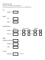
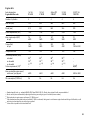
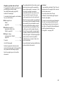
Data specific to your ve hicle
Please enter your vehicle’s data here to keep it ea sily accessible.
This information is available under the section "Technical da ta " as well as on the identification plate.
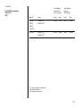
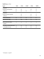
Fuel
Desi gnation
Engine oil
Grad e
Viscosity
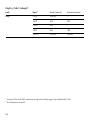
Tyre inflation pressure
Tyre si ze
wi th up to 3 persons
Front
R ear
Front
R ea r
Winter tyres
Front
R ear
Front
R ea r
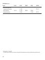
Weights
Permissible gross vehicle weig ht
–
EC k erb weight
=
Loading
Lev el control
Bump er H eig ht
0
wi th full load
Sum mer tyres
see page 144
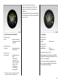
Your Zafira
Dev eloped to the la test findings of vehic le research, it offers technical sophistication and exceptiona l comfort.
Your vehicle represents an ideal synthesis of ad vanced technolog y, outsta nding safety, environm ental compatibility and economy in
opera tion.
It now lies with you to drive your vehicle safely and to see it performs perfectly.
This O wner's Manual provides you with all the necessary information to tha t end.
The O wner's Manual should a lways be kept in the v ehicle: ready to hand in the g lov e com partment.
Make use of the Owne r's Manual:
z
z
z
z
z
Its “I n brief” section will giv e y ou an initial ov erview.
Its index will help you find what y ou want.
It will familiarize you with the sophisticated technology.
It will increase your pleasure in y our vehicle.
It will help you to handle y our v ehicle ex pertly.
The O wner's Manual is designed to be clearly laid-out and easily understood.
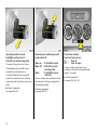
This symb ol:
6 signifies: continue reading on next page.
3 The asterisk sig nifies equipment op tions not in all vehicles (model variants, engine options, models specific to one country, op tional
equipment, Genuine Vauxhall Parts and Accessories).
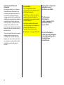
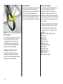
Text highlighted in yellow in p artic ular indica tes possible risk of accident and
injury. Disregard of these notes can lead to injuries which may b e fatal. Vehicle
passengers must b e informed accordingly.
Yellow arrows in the illustrations serve as points of reference or ind icate some action to be performed.
Black arrow s in the illustrations indicate a reaction or a second ac tion to be perform ed.
We w ish you m any hours of pleasurable driving
Your Va uxhall team
1
2
Contents
Comm itment to custom er
satisfaction:
Our ai m: to k eep you happy with your
vehicle. All Vauxhall Authorised Repairers
offer first class service at competitive
prices. Experienced, factory-trained
technicians w ork according to factory
instructions.Your Authorised Repairer can
supply you with GEN UINE VAU XHALLAPPRO VED PARTS , which hav e und ergone
stringent quality and precision chec ks, and
of course useful and a ttrac tiv e
VAUXHALL-APPROVED AC CESSO RIES.
Our nam e i s your guara ntee!
For d eta ils of the
Va uxhall Authorised Rep airer Netw ork
please r ing this number; 01582 - 427200
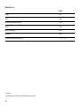
In b rief .. ..... .... ..... .... .... ..... .... ..... .... ..... .... .... . 4
Instrum ents ... ..... .... .... ..... .... ..... .... ..... .... .. 32
K eys, doors, b onnet .. ..... .... ..... .... ..... .... .. 58
S eats, Interior ..... .... .... ..... .... ..... .... ..... .... .. 71
S afety system s ... .... .... ..... .... ..... .... ..... .... .. 86
Lighting ..... .... ..... .... .... ..... .... ..... .... ..... .... 143
Windows, sun roof.. .... ..... .... ..... .... ..... .... 147
Heating and v entilation ... ..... .... ..... .... 152
Air conditioning system . .... ..... .... ..... .... 157
Electronic air conditioning system . .... 166
Automatic transm ission .... ..... .... ..... .... 176
Driving hints . ..... .... .... ..... .... ..... .... ..... .... 182
S ave fuel, protec t the env ironment .... 184
Fuel consum ption, fuel, refuelling .. .... 186
C atalytic converter, exhaust gases .... 188
Drive control system s ..... .... ..... .... ..... .... 192
Brakes ... ..... .... ..... .... .... ..... .... ..... .... ..... .... 196
Wheels, tyres . ..... .... .... ..... .... ..... .... ..... .... 200
Roof racks,
caravan and tra iler towing .... ..... .... 204
S elf-help .... .... ..... .... .... ..... .... ..... .... ..... .... 212
If y ou ha ve a problem .... .... ..... .... ..... .... 242
Maintenance, Inspec tion system ... .... 244
Vehicle care .. ..... .... .... ..... .... ..... .... ..... .... 256
Technical data . .... .... ..... .... ..... .... ..... .... 260
Index . .... ..... .... ..... .... .... ..... .... ..... .... ..... .... 276
3
In brief
Key num be rs
code numbe rs
Remove key number from key.
The key number is specified in the vehic le
docum ents and in the C ar Pass 3.
Alloy wheels 3, towing equipment 3 :
Make a note of the key identifier codes.
Elec tronic imm obiliser, Radio 3 :
The code num bers are sp ecified in the
Car Pass and Radio Pass 3 respectively .
Do not keep the Car Pass and Ra dio Pass in
the vehicle.
6 Further information – see pa ges 58, 59,
vehicle recomm issioning – see page 254.
4
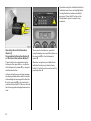
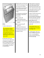
Unlock vehicle : press
button q or
turn ke y in driver’s door, lock
6 Door lock s, child restraint system –
see page 58,
electronic immobiliser – see page 59,
radio frequency
remote control – see pa ge 60,
central loc king – see pag e 62,
anti-theft locking system – see page 64,
Vauxhall alarm system 3 – see page 67.
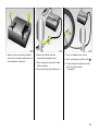
Unlock luggage compartme nt:
Turn key clockwis e as far as it will go
In order to av oid being locked out, the k ey
cannot be removed.
Position of key slot in lock:
– horizontal
tailgate is
locked
and unlocked
together with the centra l
locking,
– vertical
tailgate is always
locked.
6 Ra dio frequency remote control 3 –
see page 60,
central lock ing 3 – see p age 62,
Vauxhall alarm system 3 – see page 64.
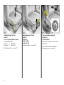
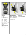
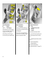
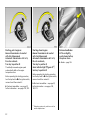
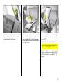
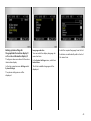
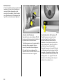
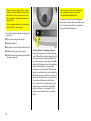
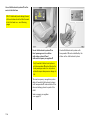
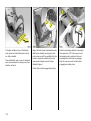
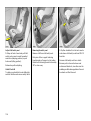
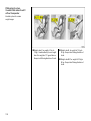
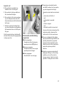
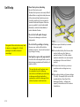
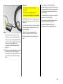
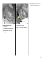
Adjust front se ats:
Pull handle,
slide seat,
release handle
Nev er adjust the driver's seat whilst d riv ing.
It could move in an uncontrolled manner
when the handle has been pulled.
6 Seating position – see p age 71,
seats in second and third rows 3 –
see p age 25.
Front seat backrest adjustm ent:
Turn handwheel
Move seat bac krest to suit sea ting position.
Do not lea n on seat when a djusting.
6 Sea ting position – see pag e 71,
seats in second a nd third rows 3 –
see page 25.
Im porta nt : Do not sit nearer than 10”
(25cm ) from the steering wheel, to
permit safe airbag dep loy ment..
5
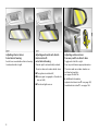
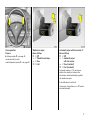
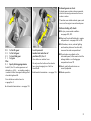
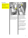
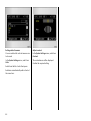
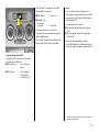
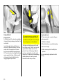
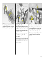
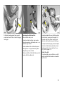
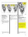
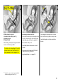
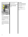
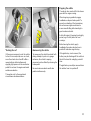
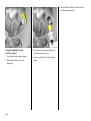
Adjusting height of front
seats 3:
Leve r on outboard side of seats
Lever pumping ac tion
Upward
=
Seat higher
Downward =
Seat lower
6 S eating p osition – see page 71.
6
Adjusting angle of front
seats 3:
Pull lever,
adjust angle,
release lever
6 Seating position – see page 71.
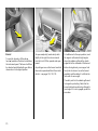
Front seat lumbar s upport 3
adjustment:
Turn handwheel
Adjust lum bar sup port to suit personal
requirements.
Do not lea n on seat when a djusting.
6 Sea ting position – see pag e 71.
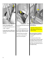
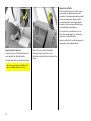
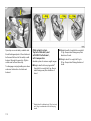
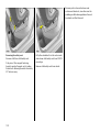
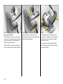
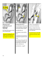
Thigh support 3 adjust position in
re lation to front seats :
Lift and s lide front support padding
Do not adjust the thigh support w hilst
driving.
6 S eating p osition – see page 71.
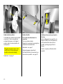
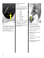
Adjust head restraint height of front
seats and outboard seats
in second row:
Tilt forward to release ,
hold and adjus t height,
release
6 Head restraint position – see page 72,
further informa tion, rem oval – see page 72,
rear head restraints 3 – see pag e 72.
7
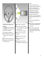
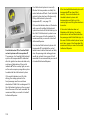
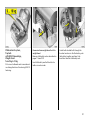
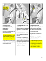
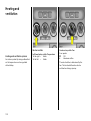
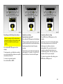
Adjusting interior m irror:
Swivel mirror hous ing
Swiv el lev er on underside of mirror housing
to red uce daz zle a t nig ht.
Adjusting automatic anti-dazzle
interior mirror 3 :
swivel mirror housing
Glare at night is automatically reduced.
The mirror does not reduc e da zzle when:
z The ig nition is sw itched off,
z Reverse gear is engaged or the selector
lever set to R,
z The interior lights are on.
8
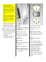
Adjusting exterior mirrors :
Four-way s witch on driver’s door
Toggle sw itc h to left or right:
Four-wa y switch m ov es app ropriate m irror.
The mirror and rear window heaters are
switched on together see pages 18 and 156.
6 Ad ditional information,
aspherical ex terior m irror 3 – see page 142,
hea ted exterior m irror 3 – see pag e 156.
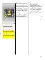
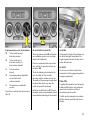
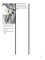
Fitting seat belt:
Draw se at be lt smoothly from
inertia ree l,
guide over shoulder
and engage in be lt buckle
The b elt must not be twisted at any point.
The lap belt must lie snugly against the
body. The front seat backrests m ust not be
tilted back too far (recommended tilting
angle approx. 25°).
To release belt, press red button on belt
buckle.
6 S eat b elts – see page 87,
airbag sy stems 3 – see p age 93,
seating position – see page 71.
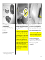
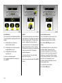
Disengaging steering column lock:
To re lease the lock,
move the s te ering wheel slightly
and turn the key to position I
Positions:
o = Ignition off
I = Steering free, ignition off
II = Ignition on
III = Start
Steering whee l adjustment 3:
Move lever down,
adjust he ight and distance,
move lever up,
engage
Adjust steering wheel only when vehicle is
stationary and steering colum n loc k is
released.
6 Airbag sy stems 3 – see page 93.
6 Starting – see page 22,
electronic im mobiliser – see pag e 59.
remove key and loc k steering w heel
– see page 23.
9
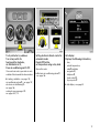
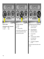
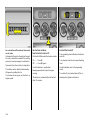
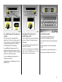
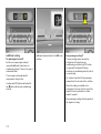
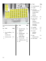
10
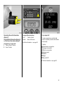
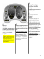
1
Page
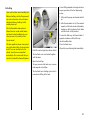
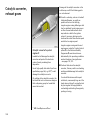
Side air v ents ... ..... .... ..... .... .... ..... .... 154
2
Front pa ssenger airbag 3 .... ..... .... . 93
3
Centre air v ents .... .... ..... .... .... ..... ... 154
4
Left hea ted sea t 3 ... ..... .... .... ..... ... 156
Fan for
rea r passeng ers 3 .... ..... .... .... .163, 173
Haza rd warning flashers .. .... ..... .... . 16
Cooling for
rea r passeng ers 3 .... ..... .... .... 163, 172
Right hea ted sea t 3 . ..... .... .... ..... ... 156
5
Radio 3,
Infotainm ent system 3 . .... .... ..... .... . 56
6
Display 3 for tim e, date,
outside tem perature,
radio 3 ,
Infotainm ent system 3,
check control 3,
trip computer 3 .... .... ..... .... .... ..... .... . 40
7
Horn . .... .... ..... .... ..... .... ..... .... .... ..... .... ..17
8
Turn signals, hea dlight fla sh,
dipped beam a nd main beam . .... . 15
Cruise control 3 .... .... ..... .... .... ..... ... 194
9
Instruments .. .... ..... .... ..... .... .... .... 32, 37
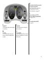
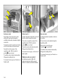
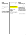
Pa ge
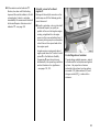
Windscreen wiper and wash,
headlight wash 3 a nd
rear window w ash 3 .... .... ..... .... ..... . 18
check control 3, trip computer 3 . . 48
Page
18 Accelerator pedal ... .... ..... .... . 182, 183
11
Light switch ..... .... ..... .... .... ..... ... 15, 143
12
Instrument illumination ... ..... .... ..... 144
Fog tail lig ht .... .... ..... .... .... ..... .... ..... 143
Fog lights 3 ..... .... ..... .... .... ..... .... ..... 143
Head lig ht range adjustment 3 .... 144
21 Accessory socket or
cigarette lighter . ..... .... ..... .... ..... .... ... 81
13
Fusebox .. .... ..... .... ..... .... .... ..... .... .... 228
23 Ashtray s ..... .... .... ..... .... ..... .... ..... .... .. 82
14
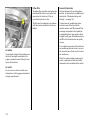
Bonnet release lev er . .... .... ..... .... ..... . 70
15
Ignition switch
with steering column lock
(not visible) . ..... .... ..... .... .... ..... .... ..... ... 9
24 Heating and v entilation .. .... ..... .... 152
Electronic air conditioning
system 3 ..... .... .... ..... .... ..... .... ..... .... . 166
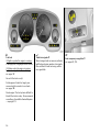
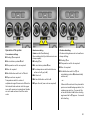
10
16
Radio / Infotainment sy stem
remote control 3 . ..... .... .... ..... .... ..... . 30
17
Steering wheel adjustm ent 3 ... ..... ... 9
19 Brake pedal .... .... ..... .... ..... .... . 182, 196
20 C lutch pedal ... .... ..... .... ..... .... ..... .... 183
22 Air circulation sy stem . ..... .... ..... .... 153
Air conditioning 3 .. .... ..... .... ..... .... 159
Heated rear w indow ... ..... .... ... 18, 156
25 Glove compartment ... ..... .... ..... .... .. 84
11
11
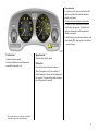
Control indicators
?
v
Airbag systems 3,
bel t tensioners,
see p ages 88, 98.
X
Sea t belt 3,
see p age 32.
R
Brake system,
clutch system,
see p ages 33, 196.
@
Electronic ally controlled
engi ne cooli ng 3,
see p age 33.
!
Preheating system 3,
see p age 33.
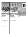
12
A
Automat ic headlig ht range
adjustment 3,
fault,
see p ages 32, 144.
Engine elect ronics,
Autom atic t ransmission 3,
Im mobil iser 3,
Fault:
see pages 33, 59, 190.
1
Automat ic tra nsm ission 3,
sp orty drivi ng progra mme,
see page 177.
v
Tra ction Control syst em (TC) 3,
Electronic Stabi lity
Progra mme (ESP) 3 ,
see pages 192, 193.
p
Alt ernat or,
see page 34.
Z
Exhaust emi ssion 3 ,
see pages 34, 190.
u
Anti-lock Brak e S ystem,
see page 198.
I
O il pressur e,
see page 34.
Y
Fuel level:
see pages 36, 39.
>
Fog light s 3,
see pages 35, 143.
g
Trailer turn signa ls 3,
see page 36.
P
Mai n beam,
see pages 15, 35.
y
Seat occup ancy recog nition 3,
see pages 99, 100.
r
Fog tai l light,
see pages 35, 143.
O
Turn signals,
see pages 16, 35.
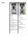
Lighting
Lig ht switch,
lev er positions,
see p ages 15, 143.
7
8
9
Lig ht s off
0
Courtesy lig ht,
see p age 145.
He ating, ve ntilation,
air conditioning system 3,
electronic air conditioning system 3
x
Pa rking l ights
Di pped and main b eam
>
Fog l ights 3,
see p age 143.
r
Fog t ail lig ht,
see p age 143.
k
Instrument illum ination,
see p age 144.
?
Hea dlight range adjustm ent ,
see p age 144.
¨
Haza rd wa rning flashers,
see p age 16.
Air quantity,
see pages 152, 158, 170.
Air distribut ion,
see pages 153, 158, 170,
Ü
Hea ted rear wi ndow,
see pages 156, 164, 169.
4
Air circ ulation syst em ,
see pages 153, 159.
n
Air condi tioning system 3 ,
see page 159.
V
To windscreen and
front door wind ow s
J
AUTO Automa tic mod e 3,
see page 167.
To windscreen, front
door windows and
footwell,
ECO
Operat ion without cooling 3,
see page 169.
K
L
M
To footwell
z
Rear passenger cooling 3 ,
see pages 163, 172.
ß
Hea ted front seats 3,
see pages 156, 164, 169.
To hea d area and to footwell
To hea d area
13
Tilt / slide sun roof 3, skylight roof 3
l
Front t ilt / slide sun roof 3,
op ening / low ering,
see p age 150.
\
Front t ilt / slide sun roof 3,
closing / raising,
see p age 150.
\
w
Rea r sk yl ight roof 3 ,
ra ise,
see p age 151.
Rea r sk yl ight roof 3 ,
lower,
see p age 151.
Winds creen wipe r
Stalk positions,
see p age 17,
§
$
%
&
14
Off
Tim ed interv al wipe
Slow
Fast
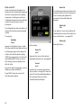
Date, time
Misce llaneous
Inform ation d isp lay 3,
see page 40,
p
Central l ocking system ,
loc king: see page 60.
Ö
O n button for date
and time,
q
;
Set button for date and time
Central l ocking system ,
unlocking: see page 60.
)
Ciga ret te lighter,
see page 81.
j
Horn,
see page 17.
/
Bonnet,
see page 70.
T
Wi nter program me,
automa tic tr ansm issi on 3,
see page 178.
+
Fir st- aid k it 3,
see page 216.
¨
Wa rning tri angle 3,
see pages 216, 217.
Radio, Infotainment system 3
St eering w heel m ount ed remote
control 3,
see page 30.
See enc losed operating instructions for
description.
Light switche s:
7 =
Off
8 =
Parking lights
9 =
Dipped or m ain beam
Main and dipped be am switch:
Main be am = Pus h stalk forwards
Dippe d beam = P ull stalk towards
ste ering w heel
Pull 0
= C ourtesy light
Push r
= Fog tail light
By overcoming the stalk resistance the
headlight flash is operated.
Push >
= Tail fog light 3
Headlight flash:
P ull stalk towards s tee ring wheel
6 Additional instructions – see page 143,
head lig ht switch-on monitoring –
see page 23,
head lig ht ra nge adjustment – see
page 144,
day tim e running lights – see page 143.
15
Operating turn signal lights:
Stalk in rest pos ition
Right turn =
Upwards
Left turn
=
Downwards
When the steering wheel is turned back, the
stalk automatically returns to its origina l
position. This will not hap pen when making
a m inor steering manoeuvre such as
changing lane.
When lane changing , move stalk part way ,
to first stop. When released, stalk will
spring back.
16
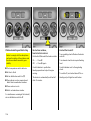
Cruise control operation:
Pre ss button on stalk
Switch on: Tap button I .
Switch off: Tap b utton § .
Resume at stored speed: Tap button R .
6 C ruise c ontrol 3 – see page 194.
Hazard w arning lights:
On
= Press ¨
Off = Press ¨ again
To aid loc ation of the pushbutton, the red
surfac e is illuminated w ith the ignition
switched on. When the button is pressed,
its control indicator flashes in time with the
hazard warning fla shers.
Horn operation:
Press j
6 Airbag sy stems 3 – see page 93,
rem ote control for ra dio
and Infotainment system 3 – see page 30.
Windscre en wiper:
Move stalk up
§ = O ff
$ = Time d inte rval wipe
% = Slow
& = F as t
Automatic wiper with rain s ens or 3 :
Move stalk up
§ = Off
$ = Autom atic w iper
with rain s ens or
% = Slow (constant)
& = Fast (constant)
Automatic wiping $: The rain sensor
detects the amount of w ater on the
windscreen and automatically regulates
the wind screen wiper.
Push stalk d ow n to switch off.
If necessary , the positions % or & can be
selected manually.
17
Operating windscre en and
headlight w as h s yste ms 3:
Pull stalk tow ards steering wheel
The w ip er will swipe for a few strokes.
The headlight wash sy stem 3 can be
opera ted when the lights are on.
O n vehicles fitted with rain sensors 3,
opera te the wind screen wash system at
reg ular intervals, to keep the sensor a rea
clean.
6 Further inform ation –
see pages 252, 257.
18
Operating re ar window wipe r and
wash systems 3:
Wiper on
Wiper off
Wash
= Push stalk forward
= Pull stalk towards
steering whe el
= Push stalk forward
and hold
The rea r window wiper operates in tim ed
interval mode. C ontinuous wip ing takes
place during washing.
6 Further information –
see p ages 252, 257.
Heated rear window,
heate d exterior mirrors:
On
= Press Ü
Off = Press Ü again
The rear window a nd ex terior mirror
hea ting is switched off automatically a fter
app rox . 15 minutes.
6 Further inform ation –
see pages 156, 164, 169.
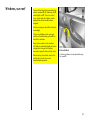
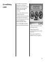
To dry miste d or icy w indows:
Turn rotary s witch for
heater and fan clockwis e,
air distribution to V ,
Press air conditioning switch n 3
Se tting ele ctronic clim ate control to
automatic mode:
Pre ss AUTO button,
set temperature using rotary knob
Close centre air vents; open side air v ents
and direct them towards the door windows.
6 Electronic air conditioning system 3
– see page 166.
6 H eating, v entilation – see page 152,
air conditioning sy stem 3 – see page 157,
electronic air conditioning 3 –
see page 166,
cooling for rear pa ssengers 3 –
see pages 163, 172.
Open all air vents.
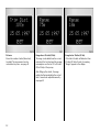
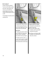
Info display:
Displays the following information;
–
–
–
–
–
–
–
time,
outside temperature,
radio 3 and date,
na vigation 3,
telephone 3,
check control 3 ,
trip computer 3
6 Info display – see pa ge 40.
19
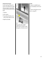
Manual transmission:
o
= Neutral
1 to 5 = 1st to 5th ge ar
When shifting up from 4th to 5th gear:
Push the lever towards the right at the
beginning of the shift opera tion.
When shifting from 5th to 4th g ear:
Do not ex ert any force towards the left.
Manual trans miss ion:
R = Re ve rse gear
Reverse gear: With vehicle stationary , pull
the ring up three seconds after declutching
and engag e gear.
If the gear does not engage: With lever in
neutra l, release clutch pedal and depress
again, then repea t gear selection.
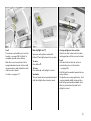
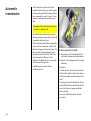
Automatic transmission 3:
P = Park
(with sele ctor lever lock)
R = Re verse
N = Neutral
Eng ine may be started only in P or N .
To mov e out of P, switch on ignition, press
foot brake and push button on selector
lever.
To eng age P or R, push button on selector
lever.
P: Only with vehicle stationary,
first ap ply handbrake
R: Only with vehicle stationary
6 Automatic transmission – see pa ge 176.
20
Exhaust gases are toxic
Exhaust g ases contain ca rbon monox ide,
which is ex tremely poisonous but has no
odour or colour.
Therefore never inhale exhaust gases, and
nev er run the engine in an enclosed space.
Before starting off, check:
z For ty re pressure and condition see pages 200, 270.
z Engine oil level a nd fluid levels in engine
compartment – see pages 244 to 252.
D =
3 =
2 =
1 =
Plus:
S =
1st to 4 th gear
1st to 3 rd gear
1st and 2 nd gear
1st gear
Lock to prevent
inadverte nt selection of
positions P , R, 3 or 1:
Sporty driving programme
Do not p ress the button on the selec tor
lever when changing from 1 to N or
from R to D.
Select 3, 2 or 1 if certain gea rs are not
desired, e. g. 4-3-4 . . . on winding roads, or
in ord er to utilize the eng ine braking effect
when d riv ing downhill.
Press button on selector lever.
6 Autom atic transmission – see page 176.
z All windows, mirrors, exterior lig hting
and number plates are free from dirt,
snow and ice a nd are operationa l.
z Do not place any objec ts on the
instrument panel, in the area in which the
airbags inflate or on the lugga ge
compartment cover 3.
z Seats, seat belts and mirrors are
correctly a djusted .
z Brake operation.
Press button on selector lever to
enga ge 3 or 1.
6 Automatic transmission – see pa ge 176
21
Starting, petrol engines:
Manual transmission: In neutral
with clutch de press ed
Autom atic transmission: In P or N,
Do not accelerate
Turn key to position III
The initially increased engine speed
automatically fa lls as the engine
tem perature rises.
Before repeating the starting proced ure,
turn the key ba ck to o in the ig nition switch,
rem ov e it and then reinsert it.
6 Electronic imm ob iliser – see page 59,
further information – see pages 182, 183.
Starting, diesel engine :
Manual trans miss ion: In neutral
with clutch depressed
Automatic trans miss ion: In P or N,
Do not accelerate,
Turn key to position II;
when indicator light ! goe s off1) ,
turn key to pos ition III
Before repea ting the starting proc edure,
turn the key back to o in the ignition switch,
remove it and then reinsert it.
6 Electronic immobiliser – see p age 59,
further information – see pag es 182,
183, 212.
1)
22
Prehea ting system only switches o n at low
ou tsid e temp era tures.
Release handbrake:
Lift le ver slightly,
push release button,
drop lever down
6 Brakes – page 196.
Advice whe n parking:
z Always ap ply handbrake firmly. On
slop es apply the handbrake as firmly as
possible
z With manual transmission, engage first
gear or reverse gear and with automatic
transm ission 3, pla ce selector lev er in
position P
z In vehicles with automatic transmission 3
the key can only be removed with selector
lever in position P
z C lose w indows, tilt / slide sun roof 3 and
skylight roof 3
Parking the vehicle :
Apply handbrake firmly,
engine off,
re move key,
lock steering whe el,
lock doors
6 Further informa tion – see pages 59, 183,
radio freq uency
rem ote control 3 – see page 60,
central lock ing sy stem 3 – see page 62,
Vauxhall alarm system 3 – see page 67.
z Remove key , otherwise an alarm will
sound when the d riv er’s door is opened
z Turn steering wheel until lock engages
(anti-theft protection)
z Sw itch off exterior lights, otherwise the
hea dlight warning devic e 3 will sound
when the driver’s door is opened
z Engine cooling fan may run on after the
eng ine has been switc hed off
Service work,
Mainte nance
We rec om mend that y ou entrust all work to
a Vauxhall Authorised Rep airer, w ho c an
provide you with reliable service and
correc tly perform a ll work according to
factory instructions.
6 If you have a problem – see page 242.
6 Further informa tion – see pages 253, 254
23
Genuine V auxhall Parts and
Acces sories
We recommend that you use " Genuine
Vauxhall Parts a nd Accessories" and
conversion parts released expressly for
your vehicle ty pe. These parts have
undergone special tests to establish their
reliab ility , safety and specific suitability for
Vauxhall vehicles. Despite continuous
market monitoring, we cannot assess or
guarantee these attributes for other
products, ev en if they have been granted
approva l by the relevant authorities or in
som e other form.
"Genuine Vaux ha ll Pa rts and Ac cessories"
and ap prov ed conv ersion p arts are
ava ilab le from a Vaux hall Authorised
Repairer, who can provide ex pert adv ice,
suc h as advice on permissible technica l
modifications, and install prod ucts
correctly .
24
For your s afety
C arry out regularly the check s
rec om mended in the indiv idual sections
of this Owner's Manual.
Ensure that y our v ehicle is serv iced as
specified in the S ervice Booklet. We
rec om mend that you consult a Vauxhall
Authorised Repairer.
Hav e faults remedied without d elay!
C onsult a workshop. We recommend a
Vauxhall Authorised R epairer. If
necessary , interrupt your journey.
6 Maintenance – see pages 244 to 253.
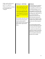
That was the most important
inform ation on your
firs t drive in your Zafira.
The othe r pages
of this chapter
contain a sum mary of the
intere sting functions
in your vehicle .
The res t of the chapters
contain important information
concerning operation, s afety
and maintenance
and a full index.
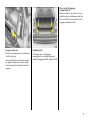
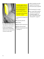
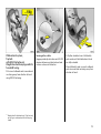
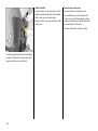
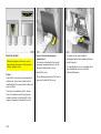
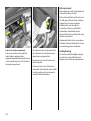
Seats in se cond row
Keep hands out of hinge area when
folding sea t backrests in second row up
or down, risk of injury.
Seat back rests must not be set to vertica l
position when transporting p ersons.
Moving seats
Push release handle on right or left hand
side of seat bench forward and move seat
row forwa rd or back. Release handle and
allow seat row to lock into p osition.
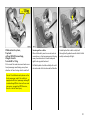
Ad just back rest s of out board seats
Push release lever down at b ackrest,
bac krest angle can be adjusted in two
places. Release handle and latch back rest
into position.
The backrest latches in several positions.
N o-one must sit in the seat when the
bac krest is in the vertical position.
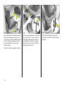
The outboard seat back rests ca n be tilted
forward until they are flat in ord er to make
it easier to enter and ex it the vehicle. Push
release lever down and tilt bac krest
forward.
To mov e the backrest upright or change
the position, push relea se lev er down a nd
latch ba ckrest in req uired position.
25
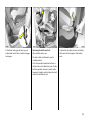
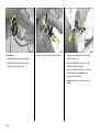
Arm rest i n tilted m iddle ba ckrest
Push midd le head restraint down as far as
it will go – see page 72.
Pull top handle at back of middle back rest,
fold back rest onto seat cushion and latch
into position.
Push rear handle of tilted bac krest and fold
armrest out.
To move backrest upright, fold a rm rest
back. Pull front handle a t backrest, move
backrest upright and latc h into position.
The back rest latches in two positions.
No-one must sit in the seat w ith the
backrest in the vertical position.
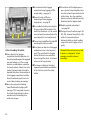
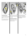
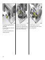
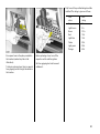
Seats in third row
Keep hands out of hing e area when
folding seat backrests in third row up or
down, risk of injury.
Mov e seats upri ght out of v ehic le floor
Removing luggage compa rtm ent cover see page 77.
Lift cushions of sec ond row of seats see page 76. Move the seat bench forward
by pushing the hand le on the rig ht or left
hand side of the seat b ench forward until
the m arking on the seat bench is level with
the adjacent m arking.
26
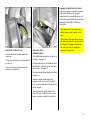
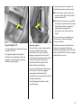
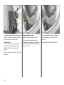
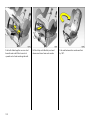
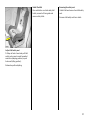
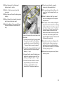
As shown in the illustration, seat b elts must
be routed throug h the fixtures and latch
plates inserted in the fixtures.
Front luggage compartment, lift seat with
one hand using handle, swivel back and
move up rig ht until it is heard to engage,
supporting top of b ackrest with other ha nd
– see Fig . 14480 T.
Lift cov er in floor between seats and swivel
seat belt buck les upward – see page 28,
Fig. 14477 T.
Remove latch plate and belt from fixture.
For use b y passengers, the belts must
not b e routed through the fix ture.
S lid e seat b ench in second row to required
position, pushing lev er to right or left of
seat bench forward – see Fig. 14473 T,
pag e 25.
27
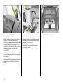
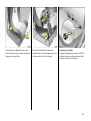
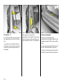
Fold seats into floor of v ehi cle
Before fold ing in the seats, m ov e the seat
benc h in the second row forward b y
pushing the handle on the right or left hand
side of the seat bench forwa rd until the
marking on the sea t b ench is level with the
adjacent marking – see page 26,
Fig. 14478 T.
Push down head restraints of seats in third
row, releasing spring catches by pressing –
see page 72.
Guide seat belt through fixture, as shown in
illustration, and insert latch pla te into
fixture.
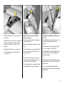
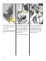
28
From lugga ge com partment, press button
at top of seat b ackrest and p ush back rest
forward. Raise seat by handle at rear and
push bac krest further forwa rd until seat is
low ered into vehicle floor.
Hold seat by handle during the entire
swiv elling proced ure.
Push b elt buckles into recess in floor a nd
close c ov er.
S lid e seat b ench in second row to required
position, pushing lev er to right or left of
seat b ench forwa rd – see Fig. 14473 T, see
pag e 25.
Installing luggage compartment cover, see
pag e 77.
Operating the multi-information
display 3,
the graphical information display 3
or the colour information dis play 3
Using but tons on wiper stalk
S
Ca ll-up / Reset / Confirm
R
Reset / Confirm
Usi ng multi func tion butt on
Push
C onfirm / select
Rota te
Move within menu
6 Further information – see p age 42.
Trip computer 3
The trip computer shows vehicle data
which it continua lly records and evaluates
electronically.
Functions:
z Instantaneous consumption
z Average consum ption
z Effective consum ption
z Average speed
z Distance
z Range
z Stop watch 3
6 Further information – see page 50.
29
Check control 3
The c heck control function monitors some
fluid lev els, the thickness of the front disk
brake linings and important exterior lights,
including c ables and fuses. When towing a
carava n / trailer the trailer lighting is also
monitored.
6 Further inform ation – see page 48.
30
Re mote control for radio and
Infotainment system 3
Radio, rad io telephone 3 and Infota inm ent
sy stem 3 functions ca n be operated using
the buttons on the steering wheel.
For further inform ation, see the respectiv e
op erating instructions.
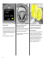
V auxhall F ull-Siz e airbag system
The Vauxhall Full-Size airbag system
comprises sev eral individual system s.
Front airb ag system
The front airbag sy stem is triggered in the
event of a serious accident involving a
fronta l impact a nd form s safety cushions
for the d riv er and front passenger. The
forward m ov ement of the driver and front
passenger is c hecked and the risk of
injuries to the upper body and head
thereby substantially reduced.
Sid e a irbag system 3
The side airbag system triggers when a
side-on collision occurs and provides a
safety barrier for the d riv er and/or
passenger in the respectiv e front door
area. This reduces the risk of injury to the
upper body c onsiderably in case of a sid e
impac t.
Curt ain airb ag system 3
The c urtain airbag sy stem triggers in c ase
of a side-on collision and provides a safety
barrier in the head area on the respective
side of the vehicle. This reduces the risk of
injury to the head considerably in case of a
side-on collision.
Active head restraints 3
P arking distance s ens ors 3
In the event of a rear-end impact, the
active head restraints automatically tilt
forwards. The head is more effectively
supported by the head restraint and the
danger of hyperextension in the neck a rea
is reduced.
The parking distance sensors
automatically switch themselves on w hen
reversing.
Ac tiv e hea d restra ints are identified by the
lettering AC TIVE on the head restra int
guid e bushes.
If the v ehicle approaches an obstacle when
reversing, a series of signals can be hea rd
in the vehicle interior. The interv al b etween
the signals becomes shorter as the
distance is reduced. If the distance is less
than 30 cm, the sig nal will be continuous.
6 Further information – see page 195.
6 Further inform ation – see page 93.
31
Instruments
Control indicators
Airb ag system s 3 ,
belt tensioners
see pages 88, 98.
?
X
Fault in autom atic head light ra nge
adjustm ent 3
Control indica tor lights up for a few
second s w hen ignition is switched on.
If it lights up when driving:
A fault has occurred . Consult a workshop
immed iately. We recommend a Vauxhall
Authorised Repairer.
Head lig ht range adjustment –
see p age 144.
32
v
The control indica tors described here are
not present in all vehic les. The descriptions
however, apply to all instrument versions.
Seat belt 3
C ontrol indicator lights up (accompanied
by an acoustic warning) when ignition is
switched on: Fasten y our seat belt – see
pag e 90.
!
Prehea ting 3 for diesel engines
C ontrol indicator lights up during
preheating.
Preheating sy stem only switches on at low
outside temperatures.
A
Engine el ect ronics, transmi ssion
electronics 3 ,
im mobil iser
C ontrol indicator lights up for a few
seconds when ig nition is switched on.
R
@
Brak e system ,
clutc h system 3
Control indicator lights up when ignition is
switched on if handbrake is applied a nd /or
the fluid level for b rake / clutch hydraulics
is too low . For further information –
see page 250.
Electronic ally controlled engine cooling 3
Control indica tor lights up when ignition is
switched on. Goes out shortly after eng ine
starts.
If it lights up when the handbrak e is not
applied: Stop the vehicle; interrupt y our
journey immediately . Consult a
work shop. We recom mend a Vaux ha ll
Authorised Repairer.
If it lights up when the engine is running:
A fault has occurred in the engine cooling
sy stem or the c ooling circuit of the air
conditioning. Driving m ay be continued.
Check coolant level – see pa ge 248. We
recommend that you consult a Va ux ha ll
Authorised Repairer.
If it lights up when the eng ine is running:
Fault in engine electronics system or
transmission electronics system . Electronics
switch to limp-home programme, fuel
consum ption may increase and driveability
of the vehicle may be impaired –
see page 190. We rec om mend that you
consult a Vaux ha ll Authorised Repairer.
If it flashes when the ignition is on:
Fault in the electronic immobiliser system ;
the engine c annot be started –
see page 59.
33
I
O il pressure
C ontrol indicator lights up when ignition is
switched on. Goes out shortly after engine
starts. Can light up interm ittently when
idling with hot eng ine; must go out when
eng ine speed is increased .
If it lights up when the eng ine is running:
Eng ine lubrication m ay be interrup ted. This
ma y result in damage to the eng ine and/or
locking of the drive wheels:
1. Depress clutch.
p
Alternat or
Control indicator lights up when ignition is
switched on. Goes out shortly after engine
starts.
If it lights up when the engine is running:
Stop the vehicle and switch off the engine.
The b attery is not being charged. Engine
cooling m ay be interrupted in v ehicles with
diesel engine. Contact a workshop. We
recom mend a Va ux ha ll Authorised
Repairer.
34
Z
Exhaust em issions 3
Control indica tor lights up when ignition is
switched on. Goes out shortly after eng ine
starts.
If it lights up when the engine is running:
Fault in emission control system . The
permitted em ission limits m ay b e
exc eeded. Consult a workshop. We
recommend a Vauxhall Authorised
Repairer.
If it flashes when the engine is running:
For fa ult that ca n lea d to destruction of the
catalytic converter - see page 190. Consult
a workshop immediately. We recommend
that you consult a Vauxhall Authorised
Repairer.
2. Move gearshift lever to neutral, or with
autom atic transmission 3 p la ce selector
lever in N.
3. Steer as quickly as possible out of the
stream of traffic, without imped ing other
vehicles.
4. Switch the ig nition off (Position I).
When the ignition is off, c onsiderab ly
more force is needed to brak e and steer.
Do not remove key until vehicle has
come to a stand still, otherwise the
steering column lock c ould engage
unexpectedly .
C onsult a workshop . We recommend a
Vauxhall Authorised Repairer.
1
Electronically cont rolled d ri ve programmes
for automatic transmission 3
C ontrol indicator lights up when sporty
driving p rogram me is operative.
Further information – see page 177.
v
Trac tion Control system (TC) 3,
Electronic S tabil ity Prog ramm e (ESP) 3
see pages 192, 193.
u
Anti -lock Bra ke Syst em (ABS ) 3
see page 198.
>
r
Fog light s 3
Control indicator lights up when fog lights
are sw itched on.
Fog t ail li ght
Control indica tor lights up when fog tail
lig ht is switched on.
P
O
Mai n bea m
Control indicator lights up when main
beam is on and when headlight flash is
opera ted.
Turn sig nal lig ht s
Control indica tor flashes when turn signal
lig hts are on. Rapid fla shes: A turn signal
bulb has fa iled.
35
Y
g
Fuel l ev el
If it lights up when the engine is running:
Fuel supply low, fuel gauge in reserve area.
Tr ailer turn signal s 3
When towing a trailer or caravan, indicator
lig ht flashes at same speed as turn signa ls.
Does not flash if trailer or towing vehicle
turn signal fails.
If it flashes when the engine is running :
Fuel tank empty. Refuel immediately –
see page 187.
Never let the tank run dry!
Petrol eng ines: Erratic fuel supply can
cause ca talytic converter to overheat –
see page 188.
Diesel engine: The fuel system is difficult to
bleed if the tank is run dry. We recommend
consulting a Vauxhall Authorised Repairer
– see pa ge 212.
36
y
Seat occupancy recogniti on 3
see pages 99, 100.
Trip odometer
To return to zero, press reset button w ith
ignition switched on and trip odometer
display activated .
Vehicles with time display in od om eter:
To return to zero, press and hold d own
reset button for ap prox . 2 seconds with
ignition switched on and trip odometer
display activated .
S witc h between trip odometer display and
time disp la y 3 by tapping the reset button
– see next pa ge.
Tachometer 1)
Spee dome ter 1)
Indicates engine speed.
Indicates the vehicle speed .
Warning: Maxim um perm itted speed
exceeded, eng ine at risk.
Odome te r
Records the m iles (kilometres) d riv en.
When the ignition is off, the num ber of
miles (kilometres) driv en can be d isplay ed
for a pprox. 15 seconds by b riefly pressing
the setting knob (arrowed).
1)
The instrum ents in yo ur vehicle m ay d iffer
from the instrum ents illustra ted here.
37
Setting t he t ime
With time displayed, press reset button in
instrument:
Press for approx . 2 seconds:
Hours flash
Press briefly :
Set hours
Press for approx . 2 seconds:
Minutes flash
Press briefly :
Set minutes
Press for approx . 2 seconds:
Clock starts at 0 seconds.
Time display in odometer 3
To sw itc h b etween trip odometer and time
display 3 give reset knob a short press.
When the vehicle lights are on, the
brightness of the display ca n be adjusted
using the right-hand knurled knob k below
the light switch – see p age 145.
Service interval display
If InSP appears in the trip odom eter display
when the ignition is switched on, the next
service interva l is due and should be
performed w ithin one week or 300 m iles
(500 km). We recomm end that you consult
a Vauxhall Authorised Rep airer.
The service interval display takes no
acc ount of off-the-roa d periods during
which the battery is d isconnected.
For this reason the maintenance intervals
spec ified in the S ervice Booklet have
priority, and should be observed –
see page 244.
38
For physical reasons, the engine
temperature gauge show s the coolant
temperature only if the coolant level is
adeq uate.
During operation the system is pressurized.
The temp erature ma y therefore rise briefly
to ov er 100 °C.
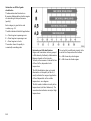
Coolant te mperature display1)
Fuel gauge1)
Pointer in zone
at left
Pointer in red
warning zone
or Y lit
Pointer between
the z ones
Pointer in red
zone at right
1)
= Engine operating
temperature not y et
reached
= Normal operating
temperature
= Temperature too
high:
Stop vehicle
and switch off
engine. Danger to
engine, check
coola nt level
immediately –
see p age 249.
= Reserve lev el
Pointer in red
warning zone
or Y flashing
= Fill up –
see pag e 187.
N ever let the tank run dry!
Diesel engines: The fuel system is d ifficult
to bleed if the tank has b een allowed to run
empty – see page 212.
O n account of the fuel remaining in the
tank, the am ount filled may be less than
the specified ta nk capacity .
The instrum ents in yo ur vehicle m ay d iffer
from the instrum ents illustra ted here.
39
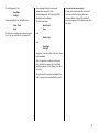
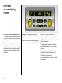
Inform ation display
Tripl e inform ation d isp lay 3
Display of time, outsid e temp erature, radio
and da te.
When the ig nition is on, the time and
outside tem perature are d isplay ed. The
date is disp la yed when the radio 3 is
switched off.
When the ignition is off, the time, date and
outside tem perature can be made to
appear for approx. 15 seconds by briefly
pressing one of the two buttons ab ov e the
display.
40
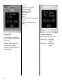
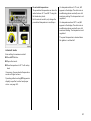
Multi-inform ation d isp lay 3
Display of time ra dio / date, outside
temperature, check control, trip c om puter.
The display operates when the ignition is
switched on. Time is continually d isplay ed
while the date is displayed when the radio
is off.
When the ignition is off, the time, date and
outside temperature can b e m ade to
appea r for approx. 15 seconds by briefly
pressing one of the two buttons above the
display or by operating one of the buttons
on the wiper stalk .
Mult i-informa tion displa y for ra dio
telephone 3
Display of time radio / date, outsid e
temperature, telephone inform ation,
check control 3, a nd trip computer 3.
The display opera tes when the ignition is
switched on. Tim e is continua lly displayed
while the date is disp la yed when the ra dio
is off.
When the ignition is off, the tim e, date and
outside temperature can be made to
app ear for app rox . 15 second s b y briefly
pressing one of the two buttons a bove the
display or by operating one of the buttons
on the wiper stalk.
I nt err up tion of pow er supp ly
After a power supply interrup tion or low
battery voltage the electronic rad io
disabler 3, da te and tim e m ust be reset.
S ee rad io operating instructions for how to
disable electronic bloc k.
Entering date and time - see page 46.
Upon receipt of a tim e signal from an RDS
transmitter 1) , date and time are set
automatically 3 – see page 46.
Grap hi cal inform ation d isp lay 3,
Col our informati on display 3
Display of date, tim e, outside temperature
and information from check control 3, trip
computer 3 and I nfotainment system .
The information displayed depends on the
vehicle equipm ent and the setting s of the
trip computer 3 and Infotainm ent system.
Fault d isplay
--,- ° C, F or S afe in the display ind icates a
fault. Ha ve the cause remed ied. We
recommend that you consult a Vauxhall
Authorised Repa irer.
The graphical information display presents
the information in m onochrome. The colour
inform ation d isplay presents the
inform ation in colour.
1)
RDS = R a dio Da ta System.
41
O peration using the multifunction button:
Individ ual menu item s are highlighted by
turning the button and are selected by
pressing it. Press the BC button on the
Infotainment system to open the trip
computer.
Operating the multi-information
display 3,
the graphical information display 3
or the colour information dis play 3
Trip computer functions are operated
using the disp la y menu and the buttons on
the wiper sta lk 3 or the Infotainment
sy stem 3.
These functions are operated using the
buttons on the wiper stalk or, on vehicles
with Infotainm ent systems 3, by using the
multifunction button.
Operation using the w iper stalk buttons:
Individual functions are selected using
button S. Certain func tions can be reset by
pressing b utton R.
If chec k control issues a warning message,
the display is blocked from other func tions.
Acknowled ge the message with b utton S or
R on the wiper stalk 3 or by pressing the
multifunction button 3 . If there are several
fault warnings, ack nowledge them one a t a
time.
42
Making system settings for
the graphical information display 3
or the colour information display 3
Lang uage selecti on
You can select the d isplay language for
some func tions.
The figures show execution with the colour
inform ation d isplay .
In the System Setti ngs menu, select item
Instructions.
In the trip computer m enu Setti ng s select
System Setting s.
The list of available languages will b e
display ed.
S elec t the required language from the list.
S elec tions are indic ated b y a 6 in front of
the menu item.
The system settings m enu will be
displayed.
43
Setti ng units of measure
You ca n select w hich units of measure a re
to be used.
Adjust contra st
In the System Setti ngs menu, select item
Contrast.
In the System Set tings menu, select item
Units.
The contrast m enu will be displayed.
Select from the list of units that opens.
Selections are indicated by a 6 in front of
the m enu item .
44
Confirm the required setting.
Outs ide tempe rature
A fall in temperature is indica ted
immediately and a rise in temp erature
after a time delay .
To warn the driver that the road surfac e
may be icy, when the temperature drops
below 3 °C the symbol : appea rs on the
display (not in all v ehicles; exceptions are
detailed to the right). When the outsid e
tem perature increases, the sy mbol : does
not disappea r from the display until the
tem perature reaches 5 °C .
On vehicles with graphical information
display 3 or colour inform ation display 3, a
message is shown in the display as a
warning for icy road surfa ces.
C aution: The road surface ma y already
be icy even thoug h the display ind ic ates
a few degrees above 0 °C.
45
Setting date and time
In the Infotainment system 3 , the da te and
time are adjusted automatically a fter
receipt of a GPS satellite signal 1 ). If the
displayed time does not match the local
time, the tim e ca n be entered manually in
steps of 30 m inutes or automa tica lly 2 )
corrected 3 by receiv ing an RDS time
signa l.
For the radio, tim e and date can be set
manually or corrected a utoma tica lly v ia an
RDS tim e signal 3 .
The a utomatic setting is indicated by Ö in
the d isplay .
Vehicles with trip le informa tion display or
multi-i nfor mati on d isplay 3:
Manua l setting
Switch off radio. Press Ö and ; a bove the
display as follow s:
Press Ö for approx. 2 seconds:
Day fla shes
Press ; : Set day
Press Ö : Month flashes
Press ; : Set month
Press Ö : Year flashes
Press ; : Set year
Press Ö : Hours flash
Press ; : Set hours
Press Ö : Minutes flash
Press ; : Set minutes
1)
2)
GPS = G lob al P ositioning System,
Sa tellite system for g loba l pos itioning.
RDS = Ra dio D a ta System.
46
Press Ö : Clock is started.
Deactivating and a ctiv ating automatic
setting 3
Hold down Ö for ap prox . 2 sec. , clock
display is now in setting m ode,
Press Ö twice (until year flashes),
Press Ö and hold down for approx.
3 seconds until } flashes in display and
text "RDS TIME" appears (yea rs flash
during this tim e).
Press ; Display indic ates:
RDS TIME 0 = Deactivated
RDS TIME 1 = Activ ated
Press Ö three tim es.
Vehi cles w ith gra phical informati on
displ ay 3 or colour informa tion displ ay 3
With the Infotainm ent sy stem on, da te and
time can be set with buttons Ö and ;
above the display :
Ö
The da te and time can also be set using the
Infotainment sy stem:
In the trip com puter menu Settings select
item S ystem S ett ings and then item
Ti me / Da te.
Press and hold down for approx.
3 seconds, menu for setting date a nd
time appears.
The menu for time / date will b e displayed.
Ö
Move within the menu.
Make the desired settings and confirm.
;
Change or confirm the setting. To
activate the settings, select O K.
Select menu item O K.
C orrecting time 3:
To correc t the time, use RDS in the
Tim e / Date m enu to select item
Auto. Ti me Correcti on .
The field behind Time Correcti on
Autom atic will be tic ked.
Select the menu item s required.
47
Check control 3
Brake Pad
Check control monitors fluid lev els, the
thickness of the front disk brake linings and
the status of important exterior lighting
components, including wires and fuses.
The lig ht monitoring function only indicates
a fault if the relev ant power circ uit is
switched on.
Front disc brake p ads are worn down to the
minimum thickness. Consult a w ork shop to
have the brake pads replac ed. We
recommend a Vauxhall Authorised
Repairer.
Brake Light
Fuse
O nce the ignition has been switched on, all
check control functions a re automatically
verified.
Fuse defective. A new fuse should only be
insta lled after the cause of the troub le has
been rectified. Fuses – see pag e 230.
The w arning
Brakelight
Check
appears on the display. It goes out after
the b ra ke pedal ha s b een depressed onc e.
Fault warnings app ear in the disp lay. O n
vehic les with multi-information display,
CH ECK also appears (not on vehicles with
radio telephone 3 ). If there are severa l
fault warning s, they a re displayed one
after the other.
Some of the fa ult w arnings appear on the
display in a n abbrev iated form.
Figure 9856 T shows the version with
multi-information display.
48
Brake Light
Fault warnings:
Engine Oil
Lev el
Engine oil level too low . Check oil level
immed iately and top up oil – see page 246.
Cool ant
Lev el
Coolant level in expansion tank too low.
Top up coolant – see page 249. Have the
cause of the fault remedied imm ediately.
We rec om mend that you consult a
Vauxhall Authorised Repairer.
Brake light failure.
Fault warnings (ctd.):
Hea dlight
Ta illight
Dipped head lig ht or ta il light fa ilure.
Ac know ledge the fault wa rning as
indica ted on pa ge 42. After
acknowledgement, the wa rning will be
cleared from the display .
The fault warning s
Wa sh. Fluid
Level
Fluid level in windscreen wash system too
low. Top up wash fluid – see page 252.
Brak e Lig ht
Fuse
I nt err up tion of pow er supp ly
C heck c ontrol automatically checks all
functions after the battery has been
reconnected or c ha rg ed. Stored fault
warnings appear on the display one after
the other.
and
Brak e Lig ht
and
Headl ight
Tail light
reappear 15 m inutes after they have been
acknowledged.
After the ignition has been switched off
and switc hed on aga in, the stored fault
warnings app ear on the disp la y one after
the other.
Once the faults ha ve been remedied , the
fa ult w arnings are automatically erased.
49
Functions:
z Instanta neous consum ption
z Average consumption
z Effective consumption
z Average speed
z Distanc e
z Range
z Stop watch (multi-information display
only)
Check control w arnings alway s hav e
priority.
Trip computer 3
The trip computer show s v ehicle data
which it continually records and evaluates
electronic ally .
Some of the functions a ppear on the
display in a n abbrev iated form.
The figures show the v ersion w ith m ultiinform ation d isplay .
50
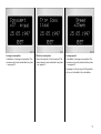
I nsta ntaneous c onsump tion
Display c hanges depending on sp eed:
Display in g al/h
below 8 m ph
(13 km /h),
Display in m pg
above 8 mph
(13 km /h).
Averag e c onsum ption
Ca lc ulation of average consumption. The
measurement can be restarted at any time
– see pa ge 42.
Effectiv e consum ption
Shows the amount of fuel consum ed. The
measurement c an be restarted at any time
– see page 42.
Av era ge sp eed
C alcula tion of av erage consump tion. The
measurement can be restarted at any time
– see page 42.
S topp ages in the journey with the ignition
off are not included in the c alcula tions.
51
Distance
Shows the number of miles (kilometres)
travelled. The measurement ca n be
restarted at any tim e – see page 42.
Range abov e 30 miles (50 k m)
The range is c alcula ted from the current
contents of the fuel tank and the average
consumption over the last 12 to 20 miles
(20 to 30 km) of the journey.
After filling up the vehicle, the range
adjusts itself automatically a fter a short
tim e. It can also be adjusted ma nually –
see p age 42.
52
Ra ng e b el ow 30 m iles (50 km)
If the fuel in the ta nk will allow less than
30 miles (50 km) of travel, the warning
"Ra ng e" appea rs in the displa y.
Resetting current trip comput er
informat ion
The follow ing trip computer information
can be reset (restart m easurements):
z
z
z
z
z
z
Range (only with vehicle stationary ),
Effective consumption
Average consumption
Average speed
Distanc e
Stop watch (multi-information display
only)
Vehicles with multi-information display:
Press button R – see page 42.
Stop wat ch 3
Ca lc ulating trav el time: The stop watch is
switched off when the ignition is switched
off and continues running once the engine
is sw itched on again. The stop watch can
be restarted at any time – see page 42.
Vehicles with gra phica l information
display 3 or colour information display 3:
S elec t the desired item from the trip
computer menu.
Then select menu item Settings.
The Settings menu is displayed.
6
53
The range values can only be reset if the
vehicle is stationary.
After resetting, " - - -" is d isplay ed with the
trip computer information selected. The
recalculated values are displayed after a
brief delay.
Reset ting m ultiple inform ation
on the tri p comp uter
The following trip com puter inform ation
can b e reset simulta neously (restart
measurements):
z
z
z
z
z
Effective consum ption
Average consum ption
Average speed
Distance
Stop watch (m ulti-inform ation d isplay
only )
Vehicles with m ulti-inform ation display :
Press button R for at lea st 2 seconds –
see page 42.
In the trip computer S et tings menu, selec t
item BC Reset present .
The v alue for the selected function will b e
reset and reca lculated.
54
Interruption of p ower supply
If the power supply has been interrup ted or
if the battery voltage has dropped too low,
the values stored in the trip computer will
be lost.
Vehicles with graphical information
display 3 or colour information display 3:
In trip com puter Setti ng s menu, select
menu item BC Reset a ll.
The values are reset and "*** " is displayed.
New va lues are only display ed when the
engine is running. The avera ge speed is
calculated shortly a fter sta rting to driv e.
55
Infotainm ent s yste m 3
The Infotainment sy stem is operated as
desc ribed in the operating instructions
supplied.
DVD video s yste m 3
The system is opera ted as described in the
AutoVision 3 opera ting instruc tions.
Radio 3
The rad io is operated as described in the
opera ting instruc tions supp lied.
The rad io display appears on the
inform ation d isplay .
Ca r radio reception will differ from
reception possible with domestic rad ios:
As the vehicle a erial is relatively near the
ground , the broa dcasting com panies
cannot guarantee the same quality of
reception as is ob tained with a domestic
radio using an overhead aerial.
56
z C hanges in distance from the
transm itter,
z Multi-path reception due to reflection
and
z Shadowing
may cause static, noise, distortion or loss of
reception a ltogether.
Mobile telephones and radio
equipm ent (CB) 3
O btain advice on predetermined
insta lla tion locations for the ex ternal
antenna a nd equipment hold er and ways
of using d evices with transmission power of
more than 10 Watts. We recommend that
y ou consult a Vaux hall Authorised
Repairer, who will have consoles and
va rious insta lla tion kits and w ill install them
in accordance with regulations.
Prerequisites for fault-free operation:
Alway s use the hands-free equipment to
ma ke telephone calls whilst driving. This
can a lso be a d istraction when d riv ing.
Plea se observe country -specific laws.
The Vauxhall installation instructions and
the opera ting guid elines provided by the
telep hone ma nufacturer must be ob served
when fitting and opera ting a mobile
telep hone. Failure to do so could invalidate
the v ehicle’ s operating permit (EU Directive
95/54/EG).
z Professionally installed exterior a erial to
obtain the maximum rang e possib le
z Max imum transm ission power 10 W
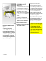
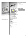
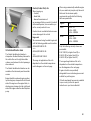
Ele ctronic data acquis ition in toll
systems
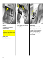
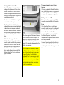
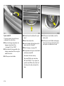
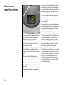
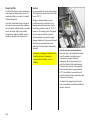
O n vehicles w ith heat-reflecta nt
windscreens 1) 3, mount the chipcard for
electronic data ac quisition and billing in
the b lack shaded zone of the windscreen
on the left or the right behind the interior
mirror, see illustration. If the chipcard is
mounted outside this zone, malfunc tions
may occur in data a cquisition.
1)
z Installation of the telephone in a suitable
spot (see note on page 101).
When used in the vehic le interior, mobile
telephones a nd radio eq uipm ent (CB)
with integrated aerial may c ause
malfunctions in the vehicle electronics.
Mobile telephones and ra dio equipment
(CB) should only be used with an aerial
fitted on the vehicle ex terior.
So la r R eflect.
57
Keys, doors,
bonnet
Re place ment ke ys
The key is a c onstituent of the electronic
immobiliser. Ordering keys from a Vauxhall
Authorised Repairer g uarantees problem free op eration of the electronic
immobiliser. Y ou will avoid unnecessary
costs, difficulties with insurance comp anies
when processing claims and problems
asserting wa rranty claims.
Locks - see pa ge 259.
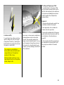
Door locking and unlocking
From outside:
Radio frequency rem ote control
– see page 60,
Central lock ing – see page 62.
From inside
Push down or pull up lock button. To
prevent the driver from being inad vertently
lock ed out, the button on the driver’s door
cannot b e depressed when the d oor is
op en.
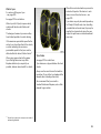
Lock cylinders
Designed to free-wheel if they are
forcefully rotated without the correct k ey or
if the correct key is not fully inserted.
To reset, turn cy linder with the c orrect key
until its slot is vertica l, remove key and then
re-insert it. If the cylinder still free-wheels,
turn the key through 180° and rep eat
op eration.
58
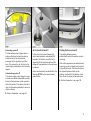
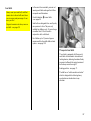
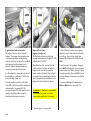
Child safety locks
Use the child safety lock whenever
child ren are occupying the rear seats.
Disregard may lea d to injuries or
endanger life. Vehicle p assengers should
be informed accordingly.
Turn rota ry knob at rear door lock from
vertical position using key: Door cannot be
opened from the inside.
Ele ctronic imm obilise r
The sy stem checks whether the vehicle m ay
be sta rted with the key that is being used .
If the k ey is recognised a s "a uthorised" the
vehic le can be sta rted. The checking takes
place in a transpond er in the key .
To act ivat e:
Switch off eng ine, turn key to position o
and remove.
To deacti vate:
Turn key to position I I (ignition on); the
engine can then b e started.
Dea ctivation is not possib le in any other
way , so keep spare key in a safe place!
Control i nd icator for imm obiliser A
When the ignition is switched on, the
control indicator A lights up b riefly.
If the control indicator flashes w hen the
ignition is on: There is a fault in the
immobiliser system. The eng ine cannot be
started:
1. Move key to p osition o in ignition lock
and remove,
If the control indicator A lights up after
the engine has started: There is a fault in
the engine elec tronics or the automatic
transmission – see pages 180, 190.
2. Reinsert key into ig nition lock,
The Car Pass contains all of the vehicle’s
data and should therefore not be kept in
the vehicle.
3. Repeat starting procedure.
If the control indicator A continues to
flash, try to start the engine using the spare
key and consult a workshop. We
recommend a Vauxhall Authorised
Repairer.
Not e
The immobiliser does not lock the doors.
Therefore, alwa ys lock the vehicle before
leaving it unattended and enable antitheft ala rm system 3 – see pag e 67.
Hav e y our Car Pass on hand when
consulting a Vauxhall Authorised Repa irer.
59
C entra l lock ing system,
see page 62.
Mechanic al anti -theft locki ng system 3 ,
see page 64.
Vauxhall ala rm system 3,
see page 67.
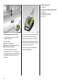
Radio fre quency re mote control
The rad io frequency remote control is
integrated in the key .
Used to op erate:
z Central locking system ,
z Mechanical anti-theft locking system ,
z Vauxhall ala rm system 3 .
The remote control has a range of
approxim ately 3 metres. The range can
change depending on ex ternal influences.
Point remote control at vehicle when
opera ting.
60
For your conv enience, we recommend that
the central lock ing sy stem alway s be
op erated using the remote control unit.
Handle remote control with care, protect
from moisture and high temperatures and
avoid unnecessary operation.
Function check by brief illum ination of
ha zard warning flashers.
Fault
If the central locking system cannot be
opera ted with the remote control, it m ay b e
due to the following :
z The range of the rem ote control has
been ex ceeded.
z The battery voltage of the remote
control unit is too low. Change the
battery, see following columns.
z The remote control has been repeatedly
op erated from outside the v ehicle’ s
recep tion rang e (e.g. too far from vehicle
and remote control is not recognised ).
Synchronise remote control, see
following columns.
z The c entral lock ing system is ov erloaded
as a result of repeated operation a t short
intervals. The power sup ply is cut off for
approx. 30 seconds.
z Interference from higher-power radio
waves from other sources.
For c entral locking sy stem operation using
key, see following pages. Have cause of
fault remedied. We recommend that you
consult a Vauxhall Authorised Repairer.
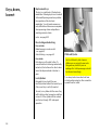
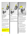
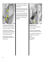
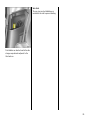
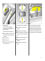
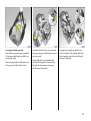
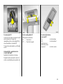
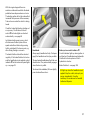
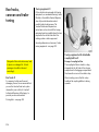
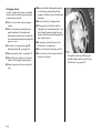
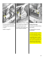
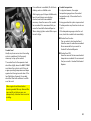
Changing the rem ote control ba ttery
Replace the battery as soon as the range
of the rem ote control starts to become
reduced.
Insert sm all screwdriver into recess in clip
and lift. Pull key part from remote c ontrol.
Ensure that the transponder in the key pa rt
is not dama ged or loosened. Flip open the
remote control. Replace batteries (for
battery type see page 272), pay ing
attention to installation position. C lose
remote control and audibly latch into key
part.
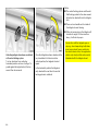
Synchronizing remote contr ol
In the ev ent of malfunctions, synchroniz e
remote control:
1. Switch on ignition; sy stem will then
remain in synchroniz ing mode for
30 seconds.
2. Briefly press button p or q on the
remote c ontrol unit with the unit inserted
in the ignition.
3. The central lock ing sy stem locks and
unlocks to show that the remote c ontrol
ha s b een sy nchronized.
The battery change must be p erformed
within 3 minutes, otherw ise the remote
control will hav e to be resynchronized.
Make sure that you dispose of old batteries
in accordance with environmental
protection regulations.
61
Not e
z To prevent the driv er from being
ina dvertently locked out, the b utton on
the driver's d oor c annot be depressed
when the door is open.
z If the driver's door is not closed properly ,
the central loc king sy stem will unlock
again immediately after lock ing.
z To loc k the d oors from insid e (e.g. to
prevent unw anted entry from outside),
push down lock button on driv er’s door.
Central locking system
For d oors, tailgate and fuel tank filler neck
cover.
To lock :
Press button p on rem ote control unit
– or –
Turn key in driver's door lock towa rd s rear
of vehic le, then turn it b ack to the vertical
position and remove. Alternatively, when
locking from inside, press the lock b utton
on one of the front doors with the doors
closed.
62
To unl oc k:
Press button q on remote control unit
– or –
Turn key in driver's door lock towards front
of vehicle, then turn it back to the vertical
position and remove. Alternatively , when
unlocking from inside, pull up the lock
button on driver's d oor.
z Locked doors unlock a utoma tica lly if an
accident of a certain sev erity occ urs (to
permit outside assistance) –
Prerequisite: Ignition m ust not be
switched off.
Cl osing window s, tilt / slid e sun roof and
skylight r oof 3
The electric wind ow s 3 , the tilt / slide
sunroof and the skylight roof can b e closed
from the outside: Insert key into driver’ s
door lock and hold in locking position until
all windows, the tilt / slide sunroof and the
skylight roof are closed.
C are must be taken w hen operating the
electric windows 3, tilt / slide sun roof 3
and sky lig ht roof 3 . There is a risk of
injury , particularly for children, and a
danger that articles could become
trapped.
Vehicle passeng ers should be inform ed
accordingly.
O verload
If the central locking system is overloaded
as a result of repeated operation at short
interva ls, the power supply is cut off for
app rox . 30 second s.
The sy stem is protected by a fuse in the
fusebox – see page 228.
K eep a close watch on the windows,
tilt / slide sun roof a nd skylight roof when
closing them. Ensure that nothing
becomes trapped in them as they move.
63
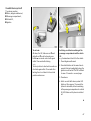
Central locking system,
mechanical anti-the ft
locking system 3
Locking
All doors must b e closed, the driv er’s door
must have been opened once previously ;
press button p on the remote control
again within 10 second s a fter locking
– or –
Turn key in driver's door lock towa rd s rear
of vehic le aga in within 10 seconds after
locking, then turn it b ack to the vertical
position and remove.
Loc k buttons on all d oors are positioned
suc h that doors cannot be opened.
Do not use the sy stem if there are p eople
in the vehicle! The doors cannot be
unlocked from insid e.
64
Unlocking
Press button q on remote control unit
– or –
Turn key in driver's door lock towards front
of vehicle, then turn it back to the vertical
position and remove.
Unlock ing is not possible in any other wa y,
so k eep sp are k ey to ha nd in a safe p la ce!
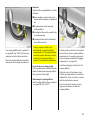
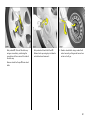
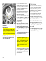
Malfunction in central locking sys te m
A = Unlock driv er’s door
Turn key in driver's door lock tow ards
front of vehicle, turning it bey ond its
resistance p oint until it will not move
any further. Turn k ey back to v ertical
position a nd remove; raise door
handle. Loc k button remains in
depressed p osition.
B = Lock driver’s door
With driver's door closed, turn k ey
towards rea r of vehicle until it will not
mov e any further. Turn k ey back to
vertical position and remove.
The other doors can be opened and closed
by pulling or pushing the interior lock
button (not p ossible if a nti-theft ala rm
system enabled beforeha nd ). Have cause
of fault remedied. We rec om mend that y ou
consult a Vaux ha ll Authorised Repairer.
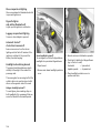
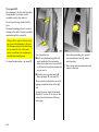
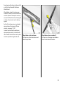
K ey slot in lock in vertical p osition:
Tailgate rema ins locked even if the vehicle
is unlock ed using the remote control or by
turning the key in the driver's door lock.
This position is to be chosen if the tailgate
is to stay lock ed. Turn key anticlockwise as
far as it will go.
6
Tailgate
Loc king and unlocking using the remote
control or key in the driv er’s door lock
together with central locking of d oors and
fuel tank cover - see p age 62.
See following columns for restrictions.
The lock is released by pressing the button.
Use of centra l lock ing system for t ailga te
The central lock ing sy stem and the antitheft locking system for the doors cannot
be sw itched on or off from the tailgate lock.
Key slot in loc k in horiz ontal p osition:
Ta ilg ate is locked and unlocked using the
remote control or by turning the key in the
driver's door lock.
If the key is only turned to the horizonta l
position after unlocking the central locking
sy stem, the tailgate remains locked .
Unlock ing – see nex t page.
65
Not e
z The central lock ing sy stem and the antitheft locking sy stem for the doors cannot
be lock ed or unlocked from the tailgate
loc k.
z There a re two handles on the inside of
the tailgate to assist closing.
z Fitting of accessories on the tailgate will
increase its weight. If it becomes too
heavy , it will not stay open.
Unlock ing tailg ate w hen doors are loc ked
wi th central loc king syst em
Turn key clockwise from vertical or
horiz ontal position as far as it will go. To
guard ag ainst being locked out, the k ey
cannot then be rem ov ed.
66
Once the tailgate has been closed and the
key turned bac k to the horizontal or
vertical p osition, the tailga te is locked
again.
In the horizonta l position the tailga te is
only unlocked the next tim e the central
lock ing sy stem is unlock ed.
Do not drive with the tailgate open or
ajar, e. g. when transporting bulky item s,
since toxic exhaust fumes could enter
the vehicle interior. Also, the registration
plate is only c learly v isible and correctly
illuminated with the tailg ate c losed .
Vauxhall alarm s yste m 3
The system monitors;
z Doors, tailgate and bonnet,
z Passenger compartment,
z Vehicle tilt,
z Ignition
To activ ate:
All doors, the tilt / slide sun roof 3 and
sky light roof 3 must be closed ; press
button p on rem ote control unit ag ain
within 10 seconds after locking
– or –
Turn key in d riv er's door lock towards rea r
of vehicle again within 10 sec onds after
lock ing , then turn it back to the v ertical
position and remove.
Sw itching on without m onitoring of t he
pa ssenger comp artment a nd the vehicle
ti lt
e.g. if anim als a re to be left in the vehic le.
1. Close tailgate and b onnet.
2. Press b oth buttons at the same time to
operate the front reading lig hts when the
ignition is switched off. The LED will fla sh
for max. 10 seconds – see next pag e.
3. Close doors.
4. Switch on anti-theft alarm system . LED
lights up. After approx. 10 sec onds the
sy stem is activated, without monitoring
of the p assenger compa rtm ent or v ehicle
tilt. LED flashes until system is switched
off.
6
67
2. Open tailgate.
3. Close tailgate.
4. To loc k: Turn key back to prev ious
position. Passenger com partment
monitoring, lugga ge c om partment
monitoring and monitoring of vehicle tilt
is switched on again after approx.
10 seconds.
To deacti vate:
Press button q on rem ote control unit
– or –
Turn k ey in driver's door loc k towards front
of vehic le, then turn it b ack to the vertical
position and remove.
68
Opening a nd closing ta ilgat e w ith
anti-theft a larm syst em acti vated
1. To unlock: Turn key clockwise as far as it
will go. The tailgate is unlocked and
monitoring of the passenger
compa rtm ent and the vehicle tilt is
deactivated.
After the first 10 seconds of anti-theft
alarm system activation:
z LED flashes
=
System on
z LED lights up
for approx.
1 second
=
Switch-off
If a system fa ult occ urs, consult a
work shop. We recom mend a Va ux ha ll
Authorised Repairer.
The system’s integ ra ted self-diagnostics
allow s faults to be quickly remedied.
Ala rm
O nly a certain num ber of a la rm s are
allowed to be trigg ered while the anti-theft
alarm system is switched on (this number is
stipula ted b y law).
The alarm takes the form of
z An acoustic signal (horn, 30 seconds)
and
z A visua l signal (hazard warning lights,
5 minutes) 1 ).
Alarm c an be stopped by pressing
button q (disa ble anti-theft alarm system)
or by pressing button p on remote c ontrol.
Light-emit ting d iode (LED)
During the first 10 seconds of anti-theft
alarm system activation:
z LED lights up =
Test, switch-on
delay
z LED flashes
=
Door, tailgate,
bonnet open
or system fault
1)
Varies from coun try to coun try on a ccount of
nationa l regu la tion s.
69
Bonnet
To open the bonnet, p ull the release
lev er / , located on the driver's side below
the instrum ent panel. The bonnet will then
be unlocked and will pa rtially open. Return
release lever to its original position.
To op en completely , locate safety catch
slightly to the right of centre as viewed
from the front: lift this upwards and op en
bonnet.
To hold bonnet in the open position, insert
the support rod located at right angles
abov e the radiator grille into the plasticedged slot in the und ersid e of the bonnet.
Any soiling or snow on the bonnet can slide
down w hen opened and block the air inlet.
Air inlet – see pag es 153, 159, 174.
Before closing bonnet, press sup port rod
firmly into its retainer. Low er the bonnet
gradually and then allow it to fall into the
lock under its ow n weight.
The safety catch in the radiator grille must
no longer b e protruding. C heck that the
bonnet is locked in position by pulling at its
front edge. I f it is not engaged , rep eat the
procedure.
70
Seats, Interior
Adjusting the front s eats
see p age 7.
Adjusting se ats in second row
see p age 25.
Folding seats in third row
see p age 26.
Increasing luggage compartment
size by folding down the front seats
see p age 73.
Seating position
Adjust driver's seat such that with the
driver sitting upright the steering wheel is
held in the area of its upper spokes with the
driver's a rms slightly b ent.
Push p assenger seat as far b ack as
possible.
The back rests must not be tilted too far back
(recommended tilting angle approx. 25°).
Imp ortant: Do not sit nearer than 10”
(25cm) from the steering wheel, to
permit safe airbag d eploym ent.
Disregard of these instruc tions can lead
to injuries which could be fatal. Vehicle
passeng ers should be inform ed
accordingly.
71
Head restraint position
He ad res traints
The midd le of the head restraint should be
at eye lev el. I f this is not possible for
extremely tall persons, set to highest
position, and set to lowest position for
small persons.
Front seats and outboard seat s i n
second r ow
To remove head restraints:
Release the tw o springs by pressing them
and deta ch the hea d restraint.
Disreg ard can lead to injuries which
could be fatal. Vehicle p assengers
should be informed accordingly.
Adjustment - see page 7.
72
Ad justment - see page 7.
Enlarging luggage compartment:
Push head restra ints of second seat row
down as far as possible – see page 73.
Mid dle sea t in second row a nd sea ts in
thir d row
Before folding seats (see page 26), or to
improve visibility with unoccupied seats,
push head restraints down as far as
possible, pressing spring catches to
release.
If seat is oc cup ied, pull head restraint
upwards.
Luggage compartment extens ion
Max imum luggage compa rtm ent space is
achieved by removing the lug gage
compa rtm ent cover and folding over the
seats in the second and third rows a nd the
passenger backrest 3, see follow ing
desc ription.
Keep hands awa y from hinges when
folding seats or rows of seats, risk of
injury.
Armrest 3 at driver’s seat
Pull raised armrest forward against the
resista nce.
The armrest can be set to various positions
by lifting it.
There is a storag e comp artment in the
armrest – see page 84.
Armre st in tilted
middle backrest
The b ackrests of the second seat row are
only allowed to be in the v ertical position
to enlarge the luggage comp artm ent.
The seats must not be oc cup ied b y
persons in this position.
Push middle head restraint as far down as
it will go – see p age 72.
Pull top handle at ba ck of midd le backrest,
fold backrest onto seat cushion and latch
into position – see page 75.
Push rear handle of tilted bac krest and fold
armrest out.
Arm rest is held in raised position by
magnets, which is why sensitive objects
such as credit cards should not be placed
on the armrest.
To move backrest upright, fold a rm rest
back. Pull front handle a t backrest, move
backrest upright and latc h into position.
73
Lowering seats in third row int o
floor of v ehic le
Before lowering the seats, move the seat
benc h in the second row forward b y
pushing the handle on the right or left hand
side of the seat bench forwa rd until the
marking on the sea t b ench is level with the
adjacent marking – see page 26,
Fig. 14476 T.
Push down head restraints of seats in third
row, releasing spring catches by pressing –
see page 72.
Guide seat belt through fixture, as shown in
illustration, and insert latch pla te into
fixture.
74
From lugga ge com partment, press button
at top of seat b ackrest and p ush back rest
forward. Raise seat by handle at rear and
push bac krest further forwa rd until seat is
low ered into vehicle floor.
Hold seat by handle during the entire
swiv elling proced ure.
Lower b oth sea ts if required.
Push belt buckles into recess in floor and
close cover.
Slide seat bench in second row to required
position, pushing lev er to right or left of
seat b ench forward – see Fig. 14473 T,
page 25.
Raising seats in third row - see page 26.
Removing luggage compartment cover
- see page 77.
Fold ing down b ack rests of outb oard
seat s i n second row
Push down head restraints of outboard
seats in second row.
Plac e sea t belt b uck les in pockets in seat
bench.
Push lock ing lever of one or both bac krests
down, raise one or both backrests and
latch into p osition,
– or –
Push down release lever on one or both
seat back rests and fold backrests down
onto sea t bench until they latch.
To move up rig ht, push release lever down
and latch back rest in required position.
Folding d own mi ddle bac krest in second
seat row
Push m iddle head restraint down as far as
possible, pressing spring catches to
release.
Place seat belt buckles in pockets in seat
bench – see page 91, Fig. 14504 T.
Pull top ha nd le on back of midd le b ackrest,
mov e ba ckrest to vertic al position and
latch into position.
– or –
Pull top handle at back of middle ba ckrest,
fold bac krest onto seat cushion and latch
into position.
To mov e upright, pull front handle of
lowered bac krest, raise back rest and latch
into position.
75
Pull top handle on back of m iddle backrest,
move backrest to v ertical position and
latch into p osition.
Push down lev er 3 to right or left of seat
bench, m ov e sea t bench as far forward as
possible and latch into position.
To move up rig ht, press lever 3 and slid e
seat benc h to required position. Adjust
backrest angles and swivel seat cushion
down using lever 1. All positions must
audibly latch.
Lower second row and push forward s
Place seat belt buckles in seat belt pock ets
in seat b ench – see pa ge 91, Fig. 14504 T.
Fold pa ssenger sea t 3
Push p assenger head restraint down or
remove – see page 72.
Raise seat cushion in second row by
pushing handle 1 on right or left hand side
of seat bench down and p ushing up seat
benc h until it locks into position.
Fold front p assenger seat forward b y
raising release lever and latch into position.
Push down release lever 2 at both
outboard back rests, ra ise backrests and
latch into position.
76
To mov e upright, raise relea se lev er and
audibly latch front p assenger seat
bac krest.
Not es on load ing
see page 80.
Luggage compartment cover
Before operating the luggage
compartment cover the rear seat belts
must be inserted into the fixtures a t the
sides (see illustration).
To close:
Pull the cover towards the rear using the
handle and engage it in the retainers at the
sides.
Do not place any heavy or sharp-edged
objects on the cover.
Rem oving
Open the luggage comp artm ent cover.
Press the knob on the rig ht-hand side of the
cover, press the right-hand end piece to the
left, and lock in. Rem ov e the cover from the
retainer a t the right, then a t the left.
Plac e cov ers in side trim openings. The
respective "right" and "left" sides are
identified on the covers by the letters "R"
(for right) and " L" (for left).
Fitti ng
Disengage c ov ers from side trims and store
them in the glove comp artm ent.
Insert the lug gage compa rtm ent cover first
in the retainer at the left, then at the right.
Press the k nob on the right-hand end piece
of the lugg age com partment c ov er. The
cover locks into place.
To open:
Disengage the luggag e com partment
cover. It rolls back autom atically.
77
Safety net 3
The safety net c an be fitted behind the
second row of sea ts or, if the seats in the
second row a re folded down, behind the
front seats.
Passeng ers must not b e transported
behind the safety net.
Fitting
There are tw o installation holes in the roof
frame: O pen covers, attach rod of net at
one side and lock in p lace, ex tend rod,
attach at other side and lock in place.
78
Attac h the straps to the lashing eyes in the
floor behind the second row of seats or
behind the front seats, and tension them .
Remov ing
Tilt strap length ad justers upwards and
unhook straps.
Floor cover for luggage
com partm ent 3
When the third row of seats is not in use
and the seats are folded aw ay under the
floor, a cov er 3 can be placed over the
luggage compa rtm ent floor.
Stor age of safet y net
Roll up the removed safety net and secure
it with Velcro strip.
Raise sea t bench for second row of seats –
see page 76. Slide sa fety net into holder
below seat bench, fold seat b ench down,
enga ge.
Lashing e yes 3
The lashing eyes in the luggage
compartment are for fastening lashing
straps 3, a luggage net 3 or a safety net 3.
79
z Secure loose a rticles in lugg age
compa rtm ent using lugga ge net 3 to
prevent sliding – see pa ge 79.
z Always fit safety net 3 when
transp orting articles in lugga ge
compa rtm ent – see p age 78.
z Do not a llow the load to protrude ab ov e
the upp er edge of the back rests of the
seats in the sec ond row or, if the second
row seats ha ve been removed , abov e the
upper edg e of the front seat backrests.
z The warning triangle 3 and first-aid kit 3
must alway s b e freely a ccessib le.
Notes on loading the vehicle
z Heav y objec ts in the lug gage
com partment should be placed as far
forward as possible aga inst the engag ed
rear seat backrests or, if the rear seat
backrests are folded down, against the
front seat b ackrests. If objects a re to be
stacked, the heav ier objects should be
placed at the b ottom. Unsecured objec ts
in the luggage compartment would be
thrown forward with great force in the
event of heavy braking, for exam ple.
z Secure heav y objec ts with lashing
straps 3 a ttac hed to lashing ey es 3
(see pag e 79). If hea vy loads slip when
the vehic le is braked heavily or driv en
around a bend, the handling of the
vehicle may chang e.
80
z Do not place any ob jects on the lug gage
compa rtm ent cover or the instrument
panel. They are reflected in the g lass,
obstruct the driver's v iew and will be
thrown through the vehicle, for instance
in the event of heavy braking.
z The storage of objects in the a irba g
expansion a rea should be avoided due
to the risk of injury when the airbag
inflates.
z Do not drive with the tailgate open or
ajar, e. g. when transp orting bulky items,
since toxic ex haust fumes could enter the
vehicle interior. Also, the registration
plate is only c learly v isible and correctly
illuminated with the tailg ate c losed .
z Weights, payload and roof loa d
– see page 267.
z Driv ing with a roof load (see pages 182,
185, 204), increases the sensitiv ity of the
vehicle to crosswinds and has a
detrimenta l effec t on vehicle handling
owing to the vehicle’s higher centre of
gravity.
Disregard of these instructions ma y lead
to injuries or endanger life. Vehicle
passeng ers should be inform ed
accordingly.
The maximum power c onsumption of
electrical ac cessories m ust not ex ceed;
z 120 watts at the socket in the c entre
console and 50 w atts with the heated
seats switched on 3,
z 120 Watts a t the accessory socket 3 in
the storage compartment (when towing,
the max imum power consumption is
reduced by the wattage of the
accessories in use in the carav an or
tra iler).
Do not connect any current-delivering
acc essories, e.g. electrical charging
devices or b atteries.
Cigarette lighte r ) 3
The cigarette lighter is located in the centre
console, at the front.
Push ciga rette lighter in with ignition
switched on. Automatically sw itches off
and pops out when elem ent is glowing.
Withd ra w cigarette lighter.
Accessory sockets
The soc ket in the centre console and the
accessory soc ket 3 in the storage
compartment at the right side of the
lugg age compartment c an be used to
connect electrical accessories. The sockets
are operational when the ig nition is
switched on. With the eng ine off the
battery will beg in to discharge.
Electrical ac cessories connected to the
socket must c om ply with the electroma gnetic compa tib ility requirem ents laid
down in DIN VDE 40 839, otherwise vehicle
ma lfunctions m ay occur.
To prevent the ba ttery from d ischarging,
the accessory socket in the luggage
compartment will switch itself off
autom atic ally 15 minutes after the ignition
ha s b een switched off.
Do not d amage the sockets b y using
unsuita ble plugs.
81
Ashtrays
To be used only for ash and not for
combustible rubbish.
Disreg ard may lead to injuries or
endanger life. Vehicle pa ssengers should
be informed accordingly.
Ashtray, front 3
Press ashtray cover to op en.
82
To empty , grip b oth sides of the ashtray
insert a nd pull upwards.
Ashtrays, rear 3
To open, swivel the cover upwards.
The rear ashtrays can be rem oved for
emptying or for use in the third row by
mov ing the cover back and forth to
disengag e it and then lifting out the
ashtray upwards.
Storage compartments in the
luggage compartment
The vehicle tool k it with the jack and towing
eye, the wa rning triangle ¨ 3 a nd the
trailer coupling ball bar are stored under a
flap in the vehicle floor at the rear 3. To
open the fla p, lift the ca rp et. Rotate and lift
the m etal ring.
Spa re wheel storage 3 – see p age 218.
Store first-aid k it in compartment in side
trim + 3 – see pa ge 216.
The right sid e trim contains a storage
compartment with an accessory socket 3
– see page 81 and the ty re repair kit 3
– see page 224.
To op en the side trim flaps rotate the
fa steners through 90°, and to close them
turn the fa steners all the wa y bac k again.
Storage compartment 3 beneath
passe nger seat
Lift tray by grasping recessed ed ge a nd
pull forwards. Max imum load: 1 kg. To
close the tray push it in and loc k it in place.
When ob jects are stored in the
compartments in the side trim, m ake sure
the free movement of the seat belts and
their automatic retrac tors is not impaired .
83
Glove com partm ent
To open, pull hand le.
O n the inside of the glov e c om partment
cover there is a pen holder.
Storage com partm ent in
front armre st 3
To open, press button and open top pa rt of
armrest.
Drink holders 3
These are located at the front underneath
the ashtray and in the front door pockets.
More drink holders can be found in the
midd le ba ckrest in the second seat row in
the folded-down position – see page 75.
Push rear hand le of tilted backrest and fold
armrest out.
Raise drink hold er and la tc h into position.
84
Sun visors
The sun v isors can be folded down or
swiv elled to the side to prevent dazzling.
Drink hold ers can also be found in the side
storag e comp artments adjacent to the
third seat row.
85
Safety systems
Three-stage re straint system
Comprising:
z three-point seat belts
z Belt tensioners at the front seats
z Airbag system s for driv er, front
passenger 3 and outboard rear seats
The three stag es are a ctivated in sequence
depending on the seriousness of the
accident:
z The automa tic seat belt locking devices
prevent the belt strap from being pulled
out and thus ensure that the v ehicle
occupants are retained in their seats.
z The front seat b elt buckles are p ulled
downwards. As a result, the seat b elts
are instantaneously tightened and the
occupants are made aware of the
deceleration of the vehicle at a v ery ea rly
stage. This reduces the stress placed on
the body.
z The airbag sy stems a re also triggered in
the ev ent of serious accidents and form a
safety cushion for the occupants.
86
The airbag sy stems 3 supplem ent the
three-point seat belts and belt
tensioners. The seat belts must therefore
always be worn. Disregard of these
instructions may lea d to injuries or
endanger life. Vehicle p assengers should
be informed accordingly.
Be sure to read the detailed descriptions of
the three-stage restra int system and the
child restraint system on the following
pag es!
Seat belts
Alwa ys wea r your seat belt, and that
means also in urb an traffic and when
you are a rear seat passenger. It can
save y our life!
Pregnant women m ust alwa ys wear a
seat belt – see page 90.
In the event of an accident, persons not
wearing sea t belts enda ng er their fellow
oc cup ants and themselves.
Control indica tor
– see page 32.
X for
seat belts
Sea t belts are desig ned to be used by only
one person at a time. They a re only
suitable for children up to 12 yea rs of ag e
or sma ller than 150 cm if used in
conjunction with a child seat.
For children up to 12 y ears of age we
recommend the Vauxhall child restraint
sy stem – see pa ge 103.
Three-point seat belts
The vehicle is equipped with three-point
seat belts with automatic retrac tors and
locking d evices, allowing freedom of body
mov ement although the spring tensioned
belts always ensure a snug fit.
S eating position - see p age 71.
The belt has a " vehicle sensitive retra ctor"
which is designed to lock during hea vy
acc eleration or deceleration in any
direction.
87
Belt tens ioners
The front sea t belt system incorporates belt
tensioners. In the event of a head -on or
rea r-end collision, d epending on the
severity of the accident, the belt buckles
are pulled d ow nwa rd s; the diagonal a nd
lap b elts are instantaneously tightened.
Actuati on of belt tensioners
Indicated by the control indicator v. Belt
tensioner actua tion ma y also be indicated
by y ellow tabs on the belt buck les.
The belt tensioners must be replaced after
activation. We recommend that you
consult a Vauxhall Authorised Repairer.
If the seat belts are unda maged the
op eration thereof is unaffected, even if the
belt tensioners have been triggered.
88
C ont rol indic ator for b elt tensioners v
The belt tensioners are electronically
monitored together with the airbag
systems and the operation thereof is
indicated on the instrument panel by the
control ind icators v. When the ignition is
switched on, the control ind ic ators
illuminate for a pprox. 4 seconds. If they do
not illumina te, or they do not go off within
4 seconds, or illum inate whilst driving, there
is a fa ult in the belt tensioner system or the
airbag sy stems – see pag e 98. The b elt
tensioner or the airbag systems ma y not
activa te if an a ccident occurs.
Have the cause of the fault remedied .
We recom mend that y ou consult a
Vauxhall Authorised Rep airer.
The system ’s integrated self-diagnostics
allows faults to be quickly remed ied. H ave
your C ar Pass on hand when consulting a
Vauxhall Authorised Repairer.
Imp or tant
z Accessories and other objects must not
be affixed or placed within the action
zone of the belt tensioners a s this may
result in injury if the belt tensioners are
triggered.
z Do not mak e any modifications to the
components of the belt tensioners, as
this will render the vehicle
un-roa dworthy .
Imp roper handling (e. g. removal or
installation) could cause the belt
tensioners to be trigg ered. Risk of injury !
z The belt tensioner and airbag sy stem
control electronics can be found in the
centre console area. In order to av oid
malfunctions, do not store mag netic
objects in this a rea.
z We recom mend that you have the front
seats removed by a Vauxhall Authorised
Repairer.
z The belt tensioners only actuate once.
Please replace belt tensioners that have
been triggered. We recom mend tha t you
consult a Vauxhall Authorised Repairer.
z Applicable safety directives must always
be ob served when disposing of the
vehicle. For this reason, d isposal should
be done by an authorised recy cling
company. We recommend that you
consult a Vauxhall Authorised Repairer.
89
Using the belts
Fitting the b el t
Pull the belt out of the retractor and guide
it across the body , making certain that it is
not twisted.
Insert latch plate into buckle. Backrest
must not be tilted too far back , sinc e this
would affect the opera tion of the seat
belts; recommended tilting a ng le app rox .
25°. The lap belt m ust be stra ig ht and lying
snugly against the body . Tighten lap belt
at frequent intervals whilst driving by
tugging diagonal pa rt of belt.
90
O n pregnant women in particular, the
lap belt must be positioned as low as
possible ac ross the pelv is so as not to put
too much pressure on the abdomen.
Thick layers of clothing prev ent the belt
from fitting snugly. The belt must not rest
against hard or frag ile objects in the
pockets of your clothing (e.g . ballpoint
pen, k ey s, spectacles), since this could
cause injury. No ob jects such as handba gs,
mobile p hones etc. m ust be present
between the belt a nd your body.
Height adjustm ent
O f front and second row seat b elt upper
anchorage points:
1. Pull b elt out slig htly.
2. Press button down or push belt guide up .
3. Set desired height.
4. Allow anchorage to lock aud ibly into
position.
Do not mak e height adjustments w hilst
driving.
Adjust height such that the belt p asses
over the wearer's shoulder and rests
against the shoulder. It must not pass over
the neck or upper arm.
Rem oving t he b el t
To remove the belt, d epress the red push
button on the buckle; the belt will retrac t
autom atic ally.
Seat belts in the sec ond row
When adjusting sec ond seat row to enlarge
luggage compa rtm ent, plac e sea t belt
buckles in pockets in seat bench as shown
in figure.
The seat belt for the middle seat can only
be pulled out of the inertia reel if the
bac krest is latched in the rearmost position
91
Inspe ction of belts
Plea se check all parts of the b elt system
occasionally for dama ge a nd correct
operation. H ave da maged parts replaced .
In ca se of an accident, please replace
overstretc hed belts and triggered belt
tensioners. We recommend consulting a
Vauxhall Authorised Repairer.
Do not perform any altera tions on the
belts, their anchorages, the automatic
retrac tors or the belt buck les.
Mak e sure that b elts are not da maged or
trapped by sharp-edged objec ts.
Seat b el ts in the third r ow
O pen the cover in the floor between the
seats and pull up the belt buckles.
Remove latch plate and belt from fix ture.
For use by passengers, the belts must
not be routed through the fixture.
92
When not in use, route the seat belt
through the fix ture as shown in the
illustration, and insert the la tch plate in the
fix ture.
Exception:
Passenger sea t with seat occupancy
recognition system 3 . The seat occupancy
recognition system deactiva tes the
passenger front and side airbags if the
passenger seat is unoccupied or a
Vauxhall child restraint system with
transponders 3 has been fitted to the
passenger seat. S eat occupa ncy
recognition – see p age 99. Vauxhall c hild
restraint sy stem with transponders 3 – see
pag e 104.
Examples of events triggering the front
airbag sy stem:
Vauxhall Full-Size airbag s yste m
z Seat occupancy recognition 3,
Front airb ag
The front airbag system is identified by the
word AI RBAG on the steering wheel and
above the glov e c om partment.
z C ontrol indicator for Vaux hall child
restraint systems y with transponders 3
in the courtesy light
The front airbag system comprises:
z Airbag w ith inflator in the steering wheel
and a second one in the instrument
panel,
z Control electronics with impact sensor,
z Airbag sy stems control indicator v in
the instrument panel,
The front airb ag system is triggered:
z Depending on the severity of the
accident,
z Impact against a non-y ielding obstacle:
The front airbags are trigg ered at low
vehicle speed.
z Impact against a yield ing obstacle
(such as another vehicle): The front
airbags are only triggered at a hig her
vehicle speed.
z Depending on the ty pe of impact,
z Within the range shown in the
illustration,
z Independently of the side airbag
system 3 and curtain airbag system 3.
93
When trigg ered , the front airbags inflate in
milliseconds and form a safety cushion for
driver and front passeng er. The forw ard
movement of the driver and front
passenger is checked and the risk of
injuries to the upper body a nd head
thereby substantially reduced.
No im pairment of view will occur, because
the a irb ags inflate and deflate so quickly .
The front airbag sy stem provides
optimum p rotection when the seat,
back rest and head restra int are correctly
adjusted: Adjust the driver's seat
according to the occupant's height such
that with the driver sitting upright the
steering wheel is held in the a rea of its
upper sp ok es with the d riv er's arms
slightly bent. The front passeng er seat
should b e as far b ack as possible, w ith
the backrest upright – see p ages 5, 71.
Do not place the head, b od y, hands or
feet on the covers of the airbag sy stems.
Do not place any objects in the area in
which the airb ags inflate. Im portant
inform ation – see page 101.
The three-point seat belt must be
correctly fitted – see page 90.
94
The front airbag sy stem will not be
triggered in the ev ent of
z The ignition being switched off,
z Minor frontal collisions,
z Accidents in which the v ehicle ov erturns,
z Collisions inv olv ing a side or rear impa ct,
where it would not be of benefit to the
occupants.
Seat belts must always be worn.
The front a irb ag system serv es to
supplement the three-point seat belts.
If y ou do not wear your seat belt you risk
being seriously injured, or even thrown
from the vehic le, in the ev ent of an
accident.
If an accident occurs the belt helps to
maintain the correct seating position
that is required for the front airbag
system to provide you with effective
protection.
In addition, the front airbag sy stem will not
be triggered for the front passenger in
vehicles with seat occupancy recognition 3 if;
z The front p assenger seat is unoccupied,
z There is a p roperly fitted Va ux ha ll child
restraint system with transponders 3 .
Seat oc cup ancy recognition
– see page 99.
Vauxhall child restraint system with
transponders 3 – see page 104.
Side airb ag 3
The side a irb ag system is identified by the
word AIRBAG on the outb oa rd sides of the
front seat backrests.
The side a irb ag system c om prises:
z Airbag w ith inflator in the b ack of the
driver's a nd front passenger’ s seats
respectively ,
z C ontrol electronic s,
z Sid e imp act sensors,
z Airbag sy stems control indicator v in the
instrument panel,
z Seat occupancy recognition 3,
z C ontrol indicator for Vaux hall child
restraint systems y with transponders 3
in the courtesy light.
The side airbag sy stem is triggered;
z Depending on the severity of the
accident,
z Depending on the type of impa ct,
z Within the range shown in the illustra tion
of the driver's d oor or front passenger
door,
z Independently of the front a irba g
sy stem.
Exception: Pa ssenger seat with seat
occupancy recognition system 3. The seat
occupancy recognition sy stem dea ctivates
the pa ssenger front and sid e airbags if the
passenger seat is unoccupied or a
Vauxhall child restraint system with
transponders 3 has been fitted to the
passenger seat. S eat occupa ncy
recognition – see p age 99. Vauxhall child
restraint sy stem with transponders 3 – see
pag e 104.
95
There must be no objects in the area in
which the airb ag inflates or in the a rea
between the seat backs and the vehicle
body . Do not place the hands or arms on
the covers of the airba g systems.
Imp ortant information – see page 101.
The three-p oint seat b elt m ust always b e
correctly fitted – see page 90.
The side airba gs will not be triggered in the
event of;
z The ig nition being switched off,
z Frontal c ollisions,
When triggered, the sid e airbag inflates in
milliseconds to form a safety cushion for
the d riv er or front passenger in the
respective door area. This substantially
red uces the risk of injury to the upper body
in the event of a sid e-on collision.
96
z Accidents in which the vehicle overturns,
z C ollisions involving a rear imp act,
z C ollisions inv olv ing a sid e impact outside
the passenger cell.
In ad dition, the sid e airbag sy stem will not
be triggered for the front passenger in
versions with sea t occupancy recognition 3
if;
z The front passenger seat is unoccupied,
z There is a properly fitted Vauxhall child
restra int system with transponders 3.
Seat occupancy recognition – see
page 99. Vauxhall child restraint system
with transponders 3 – see page 104.
Curt ain airb ag 3
The c urtain airbag sy stem can b e
recognised by the word AI RBAG on the
roof pillar panelling.
The c urtain airbag sy stem comp rises:
z Airbag with inflator in the roof frame on
the driver's and front passenger side
respectively,
z Control electronics,
z Side impact sensors,
z Airbag sy stems control indicator v in
the instrument panel
The curtain airbag system is trigg ered ;
z Depending on the severity of the
accident,
z Depending on the ty pe of impact,
z Within the range shown in the illustration
of the d riv er's door or front pa ssenger
door,
When it is triggered, the curtain airbag
inflates within milliseconds and form s a
safety barrier in the head area in the first
and second row s of the respec tiv e side of
the vehicle. If a side-on collision occurs, the
risk of head injury is reduced considerably.
z Together with the side airbag system,
z Irrespective of seat occupancy
rec og nition,
z Independently of the front airbag
system.
97
There m ust be no objects in the area in
which the airbag inflates. Do not place
the hands or arms on the covers of the
airb ag sy stems. I mportant inform ation –
see pa ge 101.
Have the c ause of the fault rem edied.
We recom mend that you consult a
Vauxhall Authorised Repairer.
The sy stem’s integrated self-diagnostics
allows faults to be quickly remedied. Have
y our C ar Pass on hand when consulting a
Vauxhall Authorised Repairer.
The three-point seat belt must alway s be
correctly fitted – see page 90.
The curtain airbags will not be triggered in
the event of
z The ignition b eing switched off,
z Frontal collisions,
z Acc idents in which the vehicle overturns,
z Collisions inv olv ing a rea r impact,
z Collisions involving a side impa ct outside
the passenger c ell
98
Control i nd icator for airba g systems v
The front airb ag system, the side airbag
sy stem 3 a nd the curtain airbag system 3
are electronically m onitored together with
the seat occupa ncy recognition system 3
and the belt tensioners, and the opera tion
thereof is indicated on the instrument
panel by a control indicator v. When the
ignition is switched on the c ontrol ind ic ator
illuminates for approxim ately 4 seconds. If
it d oes not illum ina te, does not go off after
4 seconds or illuminates whilst driving,
there is a fa ult in the airbag system s, the
seat occupancy recognition system 3 or
the belt tensioners – see page 88. The
sy stems may not operate if an accident
oc curs.
Seat oc cupancy recognition 3
The seat occupancy recognition system
deactivates the front and side passenger
airbags if the front passenger seat is
unoc cup ied or a Vaux hall child restraint
system with transponders 3 has b een fitted
to the front passenger seat. The curtain
airbag sy stem remains activated to protect
the p assengers.
The c ontrol indicator for seat occupancy
recognition is loca ted in the c ourtesy lig ht.
If this control indicator lights up after the
ignition is switched on for a pprox. 4
seconds, the vehicle is equipped with seat
occupancy recognition – see page 100, Fig.
11414 T.
This c ontrol indicator lights up
permanently after the ignition is switched
on when a Vaux hall child restraint system
with transponders 3 is fitted as soon as the
system has detected the seat. O nly then
can the child restraint sy stem be transported on the front passenger's seat.
In addition, vehicles with seat occupancy
recognition can be identified b y the sticker
on the front p assenger seat – see Fig.
12193 T.
Vauxhall c hild restraint system s w ith
tra nsponders 3 a re automatically
detected if correctly fitted to the front
passenger seat. When these child restraint
sy stems are b eing used on the front
passenger seat, the front and side a irb ag
sy stems for the front p assenger seat are
deactiv ated. The curtain airbag system
remains activated. Pay attention to the
seat occupancy recognition 3 control
indica tor – see page 100.
Only Vauxhall child restraint systems
with transpond ers 3 ca n be fitted on the
front passenger seat; the use of system s
without transponders poses a danger
to life.
Vauxhall child restrain systems with
transponders 3 can b e identified by a
sticker – see Fig . 11382 A.
99
If a child restraint system is incorrectly
fitted or the transponders are faulty the
control ind icator will flash. C heck that child
restra int system has been fitted correc tly .
Fitting child restraint system w ith
tra nsponders 3, – see pag e 110.
If the control indicator does not illumina te
with a correctly installed child restraint
sy stem there is a fa ult. Risk of fatal injury to
the child. Fit child restraint system to rear
seat. Ha ve c ause of fault remedied. We
recommend that you consult a Va ux ha ll
Authorised Repairer.
Cont rol indica tors y for Vauxha ll child
restraint syst em s with t ransponders 3
The p resence of a Vaux hall child restraint
system w ith transponders 3 is indicated
after the ignition has been switched on by
continuous illumination of the c ontrol
indicator y in the courtesy light, as soon
as the seat occupancy recognition system
has detected the child restraint system.
If the control indicator is not lit while
driving, the airbag systems for the
front passenger seat hav e not been
deactivated . C hild’ s life is endangered. Fit
the c hild restra int system on the rear seat.
Hav e the cause of the fault remed ied. We
recom mend that y ou consult a Vauxhall
Authorised Repairer.
100
If no Vaux hall child restra int system with
tra nsponders 3 is installed the control
indica tor m ust neither illuminate nor flash,
since the passenger side airbag sy stems
would not actua te. H ave cause of fault
remedied. We recom mend tha t you consult
a Vaux hall Authorised Repairer.
If the Va ux ha ll child restraint system with
tra nsponders 3 ha s b een fitted
correctly, the control ind ic ator for
Vauxhall restraint systems with
tra nsponders must light up in the
courtesy light once the ignition has been
turned on.
If the control indicator does not
illuminate whilst driv ing , the airb ag
sy stems ha ve not b een deactiv ated on
the passenger side. Risk of fatal injury . In
this case, fit child restra int system to rear
seat. Ha ve cause of fault remedied . We
recommend that you consult a Vauxhall
Authorised Repairer.
z O nly protective covers whic h are
approved for y our Zafira with side
airbag 3 ma y be fitted on the front
seats. When fitting the protective covers,
mak e sure that the airbag units on the
outboard sides of the front seat
back rests a re not covered.
z Do not modify airbag sy stem
components, since this would render the
vehicle un-roadw orthy.
z Use the hooks in the roof frame only to
hang up light articles of clothing or c oa t
hangers. Do not place any objects in the
pockets of the hanging items – risk of
injury.
z The airb ag systems are triggered
indep endently of each other depending
on the severity of the accident and the
type of impa ct. The side airbag system
and the curtain airbag system are
triggered together.
z We recom mend ha ving the steering
wheel, the instrument panel, all panelling
parts, the door sea ls, the handles and
the front seats removed by a Vauxhall
Authorised Repairer.
z The belt tensioner and airbag sy stem
control electronics c an be found in the
centre c onsole area. I n ord er to av oid
malfunctions, do not store magnetic
ob jects in this area.
z Each airbag can be trig gered only once.
O nc e triggered, an airbag must be
rep laced without delay. We recomm end
that you consult a Vaux hall Authorised
Repairer.
Im portant
z Acc essories and other objects must not
be affixed or placed in the a rea in which
the airbags inflate a s they could cause
injury if the airbags are trig gered.
z Do not p la ce a ny objects between the
airb ag systems and the vehicle
occ upa nts; d ang er of injury .
z Do not stick a ny thing on the steering
wheel, instrument p anel, front seat
backrests or roof fram e in the vicinity of
the airbags, or on the front pa ssenger
seat cushion, or cover any of those areas
with other materials.
z Use only a dry cloth or interior cleaner to
clean the steering wheel, instrum ent
panel, front seat b ackrests, roof fram e
and seat cushion of the front passenger
seat. Do not use any a ggressiv e cleaning
agents.
z The speeds, d irections of m ov ement and
deform ation p roperties of the v ehicles,
and the properties of the obstac le
concerned determine the severity of the
accident and triggering of the airbags.
The degree of da mage to your vehic le
and the resulting repair costs alone are
not indicative tha t the criteria for
triggering of the airbags were m et.
If handled im properly the airbag
sy stems can be triggered in an explosive
manner - risk of injury!
z Applicable safety directives must always
be ob served when disposing of the
vehicle. For this reason, d isposal should
be done by an authorised recy cling
company. We recommend that you
consult a Vauxhall Authorised Repairer.
101
z Persons weighing less than 35 kg should
only tra vel on the rear seats. This does
not ap ply to children who are trav elling
in c hild restra int system s w ith
transponders 3.
Vehicles with front passenger a irba g can
be identified by the word AI RBAG abov e
the glove com partment a nd the warning
sticker on the side of the instrument panel,
visible when the passenger door is open.
z In v ehicles with seat occupancy recognition 3 , do not place any heavy objects
on the front p assenger seat otherwise
the airbag system s for the front
passenger seat m ay be triggered in the
event of an accident.
Vehic les with sid e airbag 3: No child
restra int system 3 m ay be fitted on the
front passenger seat; da ng er to life.
z In vehicles with seat occupancy
recognition 3, to prevent m alfunctions
do not use protective covers or sea t
cushions on the front passenger seat.
z When using a Vauxhall child restraint
system with tra nsponders 3 on the front
passenger seat, in ord er to prevent
malfunctions, no objects (e. g. plastic
sheet, stickers or heated mats) m ay b e
placed under the c hild restra int system .
Child restraint sy stems and other heavy
ob jects must not be transported on the
la ps of v ehicle occupants; risk of fatal
injury. Child restraint sy stems with
transponders 3 transported in this way
may p revent the passenger airbag
system s from trigg ering in vehic les with
seat occupancy recognition 3 .
102
A v ehicle with side airbags can b e
identified by the word A IRBAG on the
outboard sides of the front seat b ackrests.
S eat occupancy recognition 3
– see page 99.
Use of chil d restraint syst em s 3 on front
passenger's seat in vehicles wit h airba g
systems 3 and without seat oc cupancy
rec ognition 3
Vehicles with front passenger airba g 3
or side airb ags 3: c hild seats fa cing the
rea r of the vehicle (child safety cradle
and child safety seats for weight classes
0 and I, see following pa ges) must not b e
fitted to the front passeng er seat, risk of
fatal injury. C hild seats facing in the
direction of trav el (child safety seats for
weight classes I, II and I II – see following
pages) may be fitted to the front
passenger sea t p rov id ed that the seat is
moved ba ck as far as possible and the
back rest is adjusted such that the lap
belt fits snugly.
The seat occupa ncy recognition sy stem
detects Vauxhall child restraint systems
with tra nsponders 3 and deactivates the
front and side airbags at the passenger
side. The curtain a irb ag system remains
activated . Seat occupancy recognition –
see p age 99.
Vauxhall c hild restraint system s w ith
tra nsponders 3 can be identified by the
sticker on the child restraint system.
Child res traint sys te ms 3
The Vauxhall c hild restraint system is
designed specific ally for your Vaux hall and
thus provides op tim um safety for your child
in the event of impact. If a different child
safety seat is used, follow the
ma nufacturer's instructions for fitting and
use.
6
Use of child restrai nt systems 3 on
front p assenger sea t in v ehicl es
wi th airba g systems 3 a nd
wi th seat occupanc y recognit ion 3
Only Vauxhall child restraint systems
with transp onders 3 can be fitted on the
front passenger seats. Use of systems
without transponders poses a danger to
life.
103
Vauxha ll safety c radle
wi thout transponder
From birth up to a weight of 10 k g.
Va uxhall sa fety crad le with t ransponders
From b irth up to a weig ht of 10 kg.
The transponders a re integ ra ted in the
seat cushion.
Vauxhall Top S afe child safety seat
w ith or wi thout ISO -FIX atta chment,
w ith transponders
From birth up to a w eight of 18 kg.
The tra nsponders are integrated in the
seat console.
C om prising:
1 Child seat,
2 Carrying c ra dle 3 ,
3 Floor sup port 3,
4 Seat belt 3,
5 Safety supp ort.
104
Vauxha ll child sa fet y seat
wi thout transponder
From body weight of 9 1) kg to 36 kg.
Com prising:
1 Seat back
2 Safety support
3 Seat cushion
1)
Use of chil d restraint syst em s 3 on front
passenger's seat in vehicles wit h airba g
systems 3 and without seat oc cupancy
rec ognition 3
Vehicles with front passenger airba g 3
or side airb ags 3: c hild seats fa cing the
rea r of the vehicle (child safety cradle
and child safety seats for weight classes
0 and I, see following pa ges) must not b e
fitted to the front passeng er seat; risk of
fatal injury. C hild seats facing in the
direction of trav el (child safety seats for
weight classes I, II and I II – see following
pages) may be fitted to the front
passenger sea t p rov id ed that the seat is
moved ba ck as far as possible and the
back rest is adjusted such that the lap
belt fits snugly.
Vehicles with front passenger a irba g can
be identified by the word AI RBAG abov e
the glove com partment a nd the warning
sticker on the side of the instrument panel,
visible when the passenger door is open.
Vehic les with sid e airbag 3: No child
restra int system 3 m ay be fitted on the
front passenger seat; da ng er to life.
A v ehicle with side airbags can b e
identified by the word A IRBAG on the
outboard sides of the front seat b ackrests.
S eat occupancy recognition 3
– see page 99.
Use of th e s ys tem is n ot recomm ended fo r
children weig hing less tha n 11 kg.
105
Use of child restrai nt systems 3 on the
sea ts in the third row
ISO -FIX child safety seats fa cing the rea r
of the v ehicle m ust not be fitted to sea ts
in the third seat row – see following
pages.
Use of chil d restraint syst em s 3 on
front passeng er seat in vehicles
with a irbag system s 3 and
with seat occ upancy rec ognition 3
O nly Vaux hall child restraint sy stems
with tra nsponders 3 can be fitted on the
front passenger seats. Use of sy stems
without transpond ers poses a d ang er to
life.
The seat occupa ncy recognition sy stem
detects Vauxhall child restraint systems
with tra nsponders 3 and sw itc hes off the
relev ant airbag systems to protect the
child.
Sea t occupancy recognition
– see page 99.
106
Vauxhall child restraint systems with
transponders 3 can b e identified by the
sticker on the child restraint sy stem.
Note
z Children under 12 yea rs or under 150 c m
ta ll should only travel in an app ropriate
child safety seat.
z When transporting children, use the child
restraint systems suitable for the child's
weight.
z Ensure that the child restraint system is
fitted correctly.
z Only allow the child to enter and ex it on
the sid e of the vehicle fa cing away from
the road.
z The cov ers of the safety cradle and
safety seat can be wiped clean.
z Do not stic k anything on the child
restraint sy stems a nd do not cover them
with any other materia ls.
z A child restraint system whic h has been
sub jected to stress in an a ccident must
be rep la ced.
z Y ou should a lso observe the instructions
on installation a nd use supplied with the
child restraint system.
6
107
Child restraint sys tem ,
Vauxhall child s afety cradle 3
without transponders
For babies ag ed up to 10 months or
weighing up to 10 k g.
In vehicles with front passenger a irba g 3
or side airbag 3, the safety cradle must
not be fitted on the front pa ssenger seat;
danger to life. In this case, fit the sa fety
cradle on one of the outer sea ts in the
second row or on one of the seats in the
third row.
108
Fastening t he chi ld's seat b el t
Plac e child in safety cradle.
Join the two shoulder belts of the sa fety
cradle as shown in the illustration and
engage in belt buckle between the child's
legs.
Ad apting to the child's size
The length and heig ht of the belts on the
safety cradle can be adjusted a ccording to
the child 's size:
To adjust length, p ull b elt strap at rear of
safety cradle or loosen it by pressing the
metal clip.
The belt must fit snug ly a cross the child's
body w ithout being too tig ht.
To adjust height, pull both shoulder belts
towards rear through slots. Then guid e
belts through slots in required position.
Securing in the v ehic le
Move child safety cradle ca rry ing handle to
up right position. Alw ays place child safety
cradle on one of the outboard rear seats
fa cing away from the direction of trav el
and fasten seat belt.
Move upp er anchorage point of vehicle
seat belt to lowest position 3
– see page 90.
O pen clip on rear of safety cradle to side.
Route the diag onal part of the vehicle seat
belt around the bac k of the safety cradle
bac krest through the open clip. Tighten
vehicle seat belt and close clip.
To disengage carrying hand le, press down
and swivel in direc tion of v ehicle seat
bac krest.
Pull v ehicle seat belt out of retractor and
route lap belt through the two guide clips
on the sid e b olsters of the safety cradle.
Fasten b elt buckle.
109
Child restraint sys tem : V auxhall
safe ty cradle with transponders 3
For babies ag ed up to 10 months or
weighing up to 10 k g.
The Vauxhall safety cradle with
transponders 3 can be identified by a
stic ker on the safety cradle – see page 106.
Do not fit a child restraint sy stem on the
front passenger seat if the v ehicle is
equipped with front passenger airbag 3
or side airb ags 3, but d oes not have seat
occ upa ncy rec og nition 3. Otherwise,
there is a risk of fatal injury.
In vehicles with front passenger airbag 3
or side airb ag 3 a nd seat occupancy
rec og nition 3, only Va ux ha ll child
restraint systems with transponders 3
may be fitted on the front pa ssenger
seat; using systems without
transp onders p oses a risk of fatal injury.
Sea t occupancy recognition 3
– see page 99.
Vauxhall c hild restraint system s w ith
tra nsponders 3 may a lso be fitted on the
rear seat.
Fastening t he chi ld's seat b el t
Plac e child in safety cradle.
Join the two shoulder belts of the sa fety
cradle as shown in the illustration and
engage in belt buckle between the child's
legs.
110
Ad apting to the child's size
The length and heig ht of the belts on the
safety cradle can be adjusted a ccording to
the child 's size:
To adjust length, p ull b elt strap at rear of
safety cradle or loosen it by pressing the
metal clip.
The belt must fit snug ly a cross the child's
body w ithout being too tig ht.
To adjust height, pull both shoulder belts
towards rear through slots. Then guid e
belts through slots in required position.
Securing in the v ehic le
Raise carrying handle of safety c ra dle.
Alw ays p la ce the safety cradle on the front
passenger seat with the belted child fac ing
away from the direction of trav el, as shown
in the illustration.
Ad just seat b ackrest as described on
page 94.
Move upper anchorag e point of vehicle
seat belt to lowest position – see pag e 90.
Pull vehicle seat belt out of retractor and
route lap belt through the two guid e clips
on the side bolsters of the safety cradle.
Fasten belt buckle.
111
O pen clip on rear of safety cradle to side.
Route the diagonal part of the vehicle seat
belt around the back of the safety cradle
back rest through the op en clip. Tig hten
vehic le seat belt and close clip.
To disengage c arry ing ha ndle, press down
and swivel in direction of vehicle sea t
back rest.
Child restraint system,
Top Safe child s afety seat
with ISO-FIX attachment,
with transponders
Modula r system for va rious weight ranges:
z Weight class 0 with carrying crad le 1) :
From birth to a weight of 6 kg. Alwa ys
install fa cing away from direction of
travel.
1)
112
Weight clas s 0 is d efined up to 10 kg , b ut o nly
up to 6 kg in co mb in atio n with th e ca rrying
cra dle.
z Weight class 0+: from birth to a weight of
13 kg . Always install facing away from
direction of travel.
z Weight class I: For weig ht of 9 k g to
18 kg . Always install facing direction of
tra vel.
Child restraint sys tem ,
Top Safe
with ISO -FIX attachm ent,
Weight class 0 with carrying cradle 31) :
from birth to 6 kg.
Fit to one of outboard sea ts in second seat
row facing aw ay from direction of trav el
using I SO -FIX fastening.
1)
Securing in the v ehic le
Engage provided p ush-in sleev es in IS O-FIX
retainers between seat back rest and seat
cushion as shown in illustration.
Pull yellow handle at rear of child safety
seat console until both attachment struts
are fully ex tended.
Place child safety seat on one of outboard
seats in second seat row fac ing aw ay from
direction of trav el.
Weig ht cla ss 0 is d efined up to 10 kg, bu t only
up to 6 kg in com bina tion w ith the carrying
crad le.
113
Align child safety seat and simulta neously
slid e b oth extended sec uring struts into
push-in sleev es until they audibly latch into
position. Inspection windows at front of
seat c onsole indicate correct lock ing
(deta ils in figure).
Check that seat ha s engaged by pulling.
114
Rota te top fastening brack et of provided
floor support by 90°. Push in rear pins of
fa stening b ra ckets and insert into seat
console g uides until front pins engage.
Only the rear pins must be visible a fter
engaging has taken place.
Pull bottom locking pin at floor support
and extend foot to floor of vehicle. Engage
locking pin.
Fasteni ng the child's sea t belt
Place child in carrying crad le. Fit carrying
cradle flaps over child’ s la p using Velc ro
stra p.
Place carrying cradle in child safety seat
facing awa y from direction of trav el.
Guide belt buckle at front of seat console
through openings in child safety seat and
carrying cradle.
Guide child safety seat shoulder belts
through bottom guides in b ackrest and
through slits in hea d area of carrying
cradle towa rd the outsid e.
K eeping them straight, guide belts over
child’s shoulders. Push shoulder belt la tc h
plates tog ether and click into belt buckle
between child’s legs.
115
To ad just seat belt length, push m etal plate
on back of child sa fety sea t backrest a nd
tighten or slacken free end of belt.
Unbelt t he chi ld
To slacken seat belt, press red button at
child safety seat belt buckle and pull
shoulder belts out of carrying crad le
guides.
Remove child in carrying cradle from child
safety seat.
116
Rem oving t he safety sea t
Remove child from c hild safety seat.
Push pins of floor sup port fa stening
brackets and pull support out of guides.
Rota te both fastening brackets inw ard by
90° to store a way.
Pull yellow handle on seat console and
release c hild safety seat from ISO -FIX
brack ets.
Remove child safety seat from vehicle.
Remove push-in sleev es between seat
cushion and b ackrest, since otherw ise the
padd ing could be da maged when the seat
back rests are tilted forwa rd .
Child restraint system,
Top Safe
with ISO-FIX mounting,
We ight class 0+:
from birth to 13 kg
Securing in the vehicle
Eng age provided push-in sleeves in ISO -FI X
mounting s between seat b ackrest a nd seat
cushion as shown in illustration.
Fit to one of outboard seats in second seat
row facing away from direction of travel
using IS O-FIX fastening.
117
Pull yellow ha ndle at rear of child safety
seat c onsole until both attachment struts
are fully ex tended .
Place child safety seat on one of outboard
seats in second sea t row facing awa y from
direc tion of travel.
118
Align c hild safety seat a nd simultaneously
slide both ex tended securing struts into
push-in sleeves until they audibly latch into
position. Inspection windows at front of
seat console indicate correct locking
(d etails in figure).
Check that seat has enga ged by pulling.
Rotate top fastening bracket of provided
floor support by 90° . Push in rear pins of
fastening brackets and insert into seat
console guides until front pins eng age.
O nly the rear pins must be v isible after
eng aging has taken p lace.
Pull bottom locking pin at floor sup port
and ex tend foot to floor of vehicle. Engage
locking pin.
Fastening t he chi ld's seat b el t
Plac e child in safety seat.
Guide front belt b uck le at seat console
through opening in child safety seat – see
details in Fig . 14077 J.
Guide shoulder belts of child safety seat
through lower or upp er bac krest guides
depending on size of child.
Route seat belt suc h that belt does not exit
below c hild’ s shoulder level.
Guide shoulder belts over child’s shoulders
at b oth sides, keeping belts straight. Put
shoulder belt latch plates together and
click into b elt buckle between child’s legs.
To a djust sea t belt length, push m etal plate
at front of child safety seat back rest and
tighten or slacken free end of b elt – see
Fig. 13538 J, page 116.
Unbelt the c hild
To slacken belt, press red b utton on child
safety seat belt b uck le and mov e shoulder
belts to side.
119
Remove push-in sleeves between seat
cushion and backrest, since otherwise the
pad ding could be damaged when the seat
bac krests are tilted forw ard.
Remov ing the safety seat
Remove child from child safety seat.
Push pins of floor support fastening
brackets and pull sup port out of g uides.
Rotate both fa stening b ra ckets inward b y
90° to store away.
120
Pull y ellow handle at front of seat console
and release child safety seat from IS O-FIX
mountings.
Remove child safety seat from v ehicle.
Child restraint sys tem ,
Top Safe
with ISO -FIX m ountings ,
Weight class I:
from 9 kg to 18 kg
Fit to one of outboard sea ts in second seat
row facing d irection of travel using IS O-FIX
fastening .
Conversion from w ei ght cla ss 0 or 0+ to
weight cl ass I
Remove child safety seat as describ ed on
pages 116 and 120.
Guide both shoulder b elts through the
bac krest as shown in the illustration, push
latch plates together a nd insert into
brack et at back of child safety seat.
Insert child sa fety sea t belt b uc kle into
holder on seat console.
121
Push both sliders together on cross strut
beneath seat a nd tilt front cross strut
upwards out of seat console guide rails.
122
Pull front clip on child safety seat and
relea se rear fram e from seat console.
Push seat backw ard on console and turn
by 180°.
Pull front clip on c hild safety seat, insert
rea r fra me into recess in seat console and
enga ge in front position.
Push both front sliders beneath seat
tog ether and insert and engage cross strut
in recesses at front of seat console.
Securing in the vehicle
Eng age provided push-in sleeves in ISO -FI X
reta iners between sea t backrest a nd seat
cushion as shown in illustration.
123
Pull yellow ha ndle at rear of child safety
seat c onsole until both attachment struts
are fully ex tended .
Place child safety seat on one of outboard
seats in second seat row facing d irection of
travel.
124
Align c hild safety seat a nd simultaneously
slide both ex tended securing struts into
push-in sleeves until they audibly latch into
position. Inspection windows at front of
seat console indicate correct locking
(d etails in illustration).
Check that seat has enga ged by pulling.
Rotate top fastening bracket of provided
floor support by 90° . Push rear pins of
fastening brackets and insert into seat
console guides until front pins eng age.
O nly the rear pins must be v isible after
eng aging has taken p lace.
Pull bottom locking pin at floor sup port
and ex tend foot to floor of vehicle. Engage
locking pin.
Fastening t he chi ld's seat b el t
Plac e child in safety seat.
Fit safety table to child sa fety sea t in
suitable position.
Tighten belt by pulling on free end. S afety
table must lie firmly against child sa fety
seat.
First click provided individual belt into a
belt buck le on the child safety seat. Guide
belt through belt retainer in safety table,
keeping it straight, and click into other belt
buckle on c hild safety seat.
125
Adj ust child safety seat
Pull loop at front of seat and pull child
safety seat on seat console forward at
same time (sleeping position) or push
back ward (sitting p osition).
Release loop after adjusting.
Unbelt t he chi ld
To slacken, push red buttons at child sa fety
seat b elt buckles and rem ov e safety table.
126
Rem oving t he safety sea t
Remove child from c hild safety seat.
Push pins of floor sup port fa stening
brackets and pull support out of guides.
Rota te both fastening brackets inw ard by
90° to store a way.
Pull yellow handle at front of seat c onsole
and release child safety seat from ISO -FI X
brack ets.
Remove child safety seat from vehicle.
Remove push-in sleeves between seat
cushion and backrest, since otherwise the
pad ding could be damaged when the seat
bac krests are tilted forw ard.
Child restraint sys tem ,
Top Safe child safety s eat
without ISO-FIX mountings,
with transponders
Modular system for v arious
weight rang es:
z Weight class 0 with carry ing cradle1 ):
From birth to a weight of 6 kg. Always
install facing way from direc tion of
trav el.
1)
Weig ht cla ss 0 is d efined up to 10 kg, bu t only
up to 6 kg in com bina tion w ith the carrying
crad le.
z Weight class 0+: From birth to a w eight
of 13 kg. Always install facing away from
direction of trav el.
z Weight class I: For weight of 9 kg to
18 kg. Alwa ys install facing direction of
travel.
Child res traint sys te m,
Top Safe
without ISO-FIX mountings,
weight class 0 with carrying cradle 32) :
from birth to 6 kg
Fit to one of the seats in second seat row or
front passeng er seat fa cing away from
direction of trav el using vehicle seat b elt.
Do not fit a child restraint system on the
front passenger seat if the vehicle is
equipped with front passeng er airbag 3
or side airbags 3 , but does not hav e seat
occupancy recognition 3 . Otherwise,
there is a risk of fatal injury.
2)
Weig ht class 0 is defined up to 10 kg, bu t on ly
up to 6 kg in com bina tion w ith the carrying
crad le.
127
Securing in the vehicle
Place child sa fety seat on one of seats in
second row or front passeng er seat fac ing
away from direc tion of travel and p ush
right back against backrest.
Pull la tc h pla te of vehicle safety belt out of
retractor and click into relevant b elt buckle.
128
Guide lap belt of v ehicle safety belt
through both guid es beneath shell of child
safety seat and pull tight.
Pull shoulder belt of v ehicle safety belt
round back of child sa fety sea t and guide
throug h outer slit in b ackrest running in
direction of trav el.
Then g uide shoulder belt beneath belt
buckle integrated to insid e of child safety
seat and pull tight.
Fasteni ng the child's sea t belt
Place child in separate carrying crad le 3 .
Fit carrying cradle flaps over child ’s lap
using Velcro strap.
Place carrying cradle in child safety seat
facing awa y from direction of trav el.
Guide belt buckle at front of seat console
through openings in child safety seat and
carrying cradle.
Guide child safety seat shoulder belts
through bottom guides in b ackrest and
through slits in hea d area of carrying
cradle towa rd the outsid e.
K eeping them straight, guide belts over
child’s shoulders. Push shoulder belt la tc h
plates tog ether and click into belt buckle
between child’s legs.
129
Unbelt the child
To slack en belt, press red button on child
safety seat belt buckle and ta ke should er
belts out of carrying cradle guide.
Remove child in ca rry ing cradle from child
safety seat.
Remov ing the safety seat
Remove child from child safety seat.
Press red button on vehicle safety belt
buckle, remove belt from guid es at bac k,
side and beneath seat shell of child safety
seat and allow belt to reel in.
Remove child safety seat from vehicle.
To ad just seat belt length, push m etal plate
on back of child sa fety sea t backrest a nd
tighten or slacken free end of belt.
130
Child restraint sys tem ,
Top Safe
without ISO-FIX mountings,
Weight class 0+:
from birth to 1 3 kg
Securing in the v ehic le
Plac e child safety seat on one of seats in
second row or front pa ssenger seat facing
away from direction of travel and push
rig ht b ack ag ainst bac krest.
Fit to one of the seats in second seat row or
front passenger seat facing away from
direc tion of travel using vehicle seat belt.
Pull latch plate of vehicle safety b elt out of
retractor a nd click into relev ant belt buck le.
Guide lap belt of vehicle safety belt
throug h b oth guides b eneath shell of child
safety seat and p ull tight.
Do not fit a child restraint sy stem on the
front passenger seat if the v ehicle is
equipped with front passenger airbag 3
or side airb ags 3, but d oes not have seat
occ upa ncy rec og nition 3. Otherwise,
there is a risk of fatal injury.
131
Pull shoulder belt of vehicle safety belt ov er
back of child safety seat and lead through
outer slit in backrest running in direc tion of
travel.
Then guide shoulder belt b eneath b elt
buckle integrated to inside of child safety
seat a nd pull tight.
Fastening t he chi ld's seat b el t
Plac e child in child sa fety seat facing away
from direction of travel.
Guide belt buckle from seat console
through opening in child safety seat.
Guide shoulder belts of child safety seat
through lower or upp er bac krest guides
depending on size of child.
Route seat belt suc h that belt does not exit
below c hild’ s shoulder level.
132
K eeping them straight, guide shoulder
belts ov er child’s shoulders. Push shoulder
belt latch plates together and click into belt
buckle between child’s legs.
To a djust sea t belt length, push m etal plate
at front of child safety seat back rest and
tighten or slacken free end of b elt – see
Fig. 13538 J, page 116.
Unbelt the c hild
To slacken belt, press red b utton on child
safety seat belt b uck le and mov e shoulder
belts to side.
Remov ing the safety seat
Remove child from child safety seat.
In vehicles without seat occupancy
detection 3 but with side airbag 3, no
child restraint sy stem may be fitted on
the front passeng er seat; risk of fa ta l
injury.
Press red b utton on vehic le safety belt
buckle, remove belt from g uides at back ,
side a nd beneath seat shell of child safety
seat a nd allow belt to reel in.
Remove child sa fety sea t from vehicle.
Child restraint system,
Top Safe
without ISO -FIX mountings,
We ight class I:
from 9 kg to 18 kg
In v ehicles without seat occupancy
rec og nition 3 b ut w ith p assenger
airbag 3, the child restraint sy stem may
be fitted to the passeng er seat provided
that it is pushed bac k as far as possible.
133
Conv ersion from weight c lass 0 or 0+ t o
weight class I
Remove child sa fety sea t as described on
pages 130 and 133.
Insert child safety seat belt buckle into
holder on seat console.
134
Guide both shoulder belts throug h
backrest as shown in illustration and put
both la tch plates together and insert into
retainer a t rear of child safety seat.
Push sliders together on cross strut
beneath seat a nd remove front frame from
seat console g uide rails.
Pull clip at front of child safety seat and
release frame from seat console a t rear.
Push seat ba ckward on console and turn
by 180°.
Pull front c lip on child sa fety sea t, insert
rear frame into recess in seat console and
eng age in front position.
6
135
Push sliders together beneath seat at front,
insert cross strut into recesses at front of
seat c onsole and engage.
Fastening t he chi ld's seat b el t
Plac e child safety seat on sea t fa cing
direction of travel and push right b ack
against b ackrest.
Plac e child in safety seat.
Insert latch p la te of vehicle sea t belt in
buckle.
Fit safety table into recesses in child safety
seat.
Tighten belt sy stem by pulling on shoulder
belt.
Move upp er anchorage point of vehicle
seat belt to lowest position 3 .
Height ad justment – see page 90.
136
Place shoulder and lap b elts of vehicle
safety belt into safety table belt guide
together, without twisting.
Unbelt the child
Press red button on vehicle sa fety b elt
buckle, remove belt from guide and
remove safety table.
Remov ing the safety seat
Unbelt child and remove from child sa fety
seat.
Remove child safety seat from vehicle.
Adj ust child safety seat
Pull loop at front of seat and pull child
safety seat on seat console forward at
same time (sleeping position) or push
back ward (sitting p osition).
Release loop after adjusting.
137
Child restraint sys tem ,
Vauxhall child restraint seat 3
without transponder
Modular system for v arious
weight rang es:
z Weight class I: for weight of 9 kg to
18 kg; it is ad visa ble only to use weight
class I for weights of 11 kg a nd above.
Always install facing direction of travel.
138
z Weight class II: for w eight of 15 kg to
25 kg . Always install facing direction of
tra vel.
z Weight class III : For weight of 22 kg to
36 kg . Always install facing direction of
tra vel.
Child restraint sys tem :
Vauxhall child s afety seat 3 ,
Weight range I:
9 kg to 18 kg 1)
Fastening t he chi ld's seat b el t
Alw ays fit child safety seat fa cing direction
of trav el. When fitting to front passenger
seat, slide seat as far back as possible.
When fitting to front pa ssenger seat, slide
seat a s far b ack as possib le.
Plac e child in safety seat.
On vehicles w ith side airbag s 3 , no child
restraint system may be fitted on the
front passenger's seat; danger to life.
Insert diag onal and lap belts of vehicle
seat belt into belt guides on safety base.
Insert latch p la te of vehicle sea t belt in
buckle.
Insert safety base into recesses on seat
cushion.
Move upp er anchorage point of vehicle
seat belt to lowest position 3 .
Height ad justment – see page 90.
1)
Use of th e s ys tem is n ot recomm ended fo r
children weig hing less tha n 11 kg.
139
Child restraint sys tem :
Vauxhall child s afety seat 3 ,
Weight range II:
15 kg to 25 kg
Fastening t he chi ld's seat b el t
Alw ays fit child safety seat fa cing direction
of trav el. When fitting to front passenger
seat, slide seat as far back as possible
When fitting to front pa ssenger seat, slide
seat a s far b ack as possib le.
Plac e child in safety seat.
On vehicles w ith side airbag s 3 , no child
restraint system may be fitted on the
front passenger's seat; danger to life.
Insert latch plate of vehicle seat belt in
buckle.
The lap b elt of the vehicle seat belt must
pass through the two guides on the seat
cushion.
Ad just the upp er anchorage point of the
vehicle seat belt 3 so that the belt runs
along the shortest route to the height
adjuster on child safety seat.
Height ad justment – see page 90.
140
O pen flap on outer height adjuster on
safety seat, insert belt and close flap.
Withdraw pin and a djust belt position by
mov ing slide upwa rds or downwards. Allow
pin to lock into p osition.
The seat b elt must pass over the child's
shoulder, never over the neck or upper
arm.
Child restraint sys tem :
Vauxhall child s afety seat 3 ,
Weight range III:
22 kg to 36 kg
When fitting to front pa ssenger seat, slide
seat a s far b ack as possib le.
On vehicles w ith side airbag s 3 , no child
restraint system may be fitted on the
front passenger's seat; danger to life.
The safety seat for weight range I II is a lso
ava ilab le as a separate sy stem. S ee third
column for details on its use.
To change from w eig ht range I or II t o
weight ra ng e I II
Remove safety seat b y reversing seq uence
of op erations for fitting weig ht ra nges I
and II .
Fastening the child 's seat belt
Alway s fit sea t cushion facing direc tion of
travel. When fitting to front passenger
seat, slide seat as far back a s p ossible.
Detach both belt ends from the metal clip
at rear of c hild safety seat backrest and
remove belt.
Insert latch p la te of vehicle sea t belt in
buckle.
Use a screw driver to unscrew the outer
screws connecting the sa fety seat backrest
and cushion. Remove stud bolts from sea t
cushion, working from the inside. Separate
safety seat backrest from cushion.
Keep a ll parts in a safe place.
Place child on seat cushion.
The lap belt must pass through the two
guides on the seat cushion.
The seat b elt must pass over the child’s
shoulder, never over the neck or upper
arm. Adjusting up per anchorage point
of vehicle seat belt accordingly.
Height ad justment – see page 90.
141
He ad res traints
Safety acce ssorie s 3
Do not mount any ob ject or com ponent on
the head restraint unless it has been
specifically released for y our vehicle for this
purp ose. They impair the protective
prop erties of the head restraint and c ould
be thrown forward throug h the vehicle in
the ev ent of heavy b ra king or a n ac cident.
The wide ra nge of Vauxhall accessories
allows you to equip your vehicle in
acc orda nce with your own wishes. In
add ition to safety accessories, item s for
improving comfort a nd a complete ra nge
of vehicle care p roducts you will find m any
articles w hich w ill be of g reat va lue to you
when need ed.
"Genuine Vaux hall Parts a nd Accessories"
guarantee high quality a nd accurate fit.
Exterior mirrors
For the safety of pedestrians, the exterior
mirrors will swing out of their normal
mounting position in the event of a n
accident-lik e im pact. Re-engage the
mirrors in position by applying slight
pressure to the mirror housing.
Asphe rical exterior mirror 3
Increa ses the field of v ision. S lig ht
distortion means that it is somewhat
difficult to estimate the distance b etween
the v ehicle and those behind it.
142
A Vauxhall Authorised Repa irer will be
happy to advise you, for ex ample with
regard to:
z Vauxhall child restra int system s,
z Tow rope,
z Tow rod,
z Jump leads,
z Spare bulb kit,
z Spare fuse kit,
z Halogen fog lights,
z Mudfla ps,
z Magnetic lig ht,
z Wa rning triangle,
z First-aid kit,
z First-aid kit (cushion).
Lighting
Exte rior lights
Fog lights > 3
Turn light switch:
O n = Press >
O ff = Press > ag ain
or switch ignition off
7 = O ff
8 = Parking lights
9 = Dipp ed or m ain beam
Dip ped beam , main b eam and head lig ht
flash - see pag e 15.
In positions 8 and 9, the tail lights a nd
numb er plate lights are also lit.
Vehicles with daytime running lig hts 3:
With the ignition on and the light switch at
position 7 the d ipped beam is switched on
without instrument illum ination.
Driv ing in foreign countries - see pa ge 146.
C ontrol indicator > in instrument panel.
Fog tail light r
O n = Press r
O ff = Press r a gain
or switch ignition off
C ontrol indicator r in instrument panel.
Reversing lights
C om e on when reverse gear is engaged
and ig nition is sw itched on.
Turn s ignals, haz ard warning flashe rs
see p age 16.
143
Headlight range adjustm ent ?
Manual hea dlight range adjustm ent 3
Adjust headlight range to four stages of
vehic le load ing with dipped beam switched
on: Turn k nurled wheel to d esired position.
Correct adjustment of the headlight range
red uces dazzle for other road users.
z Front seats occupied
= 0
z All seats occ upied
= 1
z All seats occ upied and
load in luggage compartment = 2
z Driv er's seat occupied and
load in luggage compartment = 3
144
Automa tic Level Control S yst em 3
Controls hea dlight ra ng e in vehicles with
Xenon headlight systems. If the control
indica tor ? lights while driving, there is a
fa ult. Hav e the cause of the fault remedied
immed iately. We recommend tha t you
consult a Vauxhall Authorised Repairer.
Instrument illumination k
C om es on with ex terior driving lights.
Brightness can be adjusted with knurled
knob 3.
Information display illumination 3
Lights up when ignition is switched on.
When vehicle lights are on, brightness ca n
be adjusted w ith k nurled knob 3.
Courtes y light 0
Front reading lights 3
Com es on w hen a door is op ened. O nce the
door has been shut it g oes out
immediately , after a certain delay 3, or
when the ignition is turned on 3 .
With ignition switched on:
To keep the courtesy light on, pull the light
switch.
On
Off
= Press button
= Press button aga in
Courte sy light above
rear s eats 3
On
O ff
Light comes on
when a rea r door
is opened
= S witch setting I
= S witch setting 0
= S witch in centre
Autom atically regulated centre
console lighting 3
Spotlight in internal mirror housing.
Daylight-sensitiv e automatic control of
centre console lig hting when ig nition is on.
145
Glove com partm ent lighting
Glove c om partment is illuminated when lid
is open and ignition on.
Cigarette lighte r
and as htray illumination 3
Lights up w hen ignition is switched on.
Luggage compartment lighting
Com es on when tailgate is opened.
Autom atic s hut-off
of electrical consumers 3
Some consum ers such as the interior
lighting sw itch off after 30 m inutes if the
ignition is switched off, to prevent the
battery from discharging.
Headlights when driving abroad
The a ssymetrical dipped beam extend s
visibility at the ed ge of the road at the
passenger side.
This causes glare for oncom ing traffic if the
vehic le is driven in countries where traffic
drives on the opposite side of the road.
Halog en headl ight system 3
To avoid glare, place masking strips on
both head lig hts. We recomm end that y ou
consult a Vauxhall Authorised Repairer.
146
Xenon headlig ht system 3
To avoid glare, switch both dipped beam
headlights to sy mmetrica l dipped beam:
1. O pen bonnet.
2. Remove main beam head lig ht protective
cover.
3. Move lev er shown in illustration upwards.
4. Check light / dark limits of dipped beam
(e.g. in front of a wall):
Horizontal
= Sym metrical
Angled upwards
= Asy mmetrical
5. Pla ce headlight protective cover in
position and close.
Windows, sun roof
C are must be taken w hen operating the
electric windows 3, tilt / slide sun roof 3
and sky lig ht roof 3 . There is a risk of
injury , particularly for children, and a
danger that articles could become
trapped.
Vehicle passeng ers should be inform ed
accordingly.
If there are children on the rear seat,
switch on the child safety sy stem 3 for
the elec tric wind ow s.
K eep a close watch on the windows,
tilt / slide sun roof a nd skylight roof when
closing them. Ensure that nothing
becomes trapped in them as they move.
Before lea ving the v ehicle, remove the
ignition key in order to p revent
unauthorized opera tion.
Door windows
The door wind ow s c an be op erated using
the crank 3.
147
Ele ctric windows 3
O peration with ignition switched off.
Two or four rocker switches in handle on
driver's door: Upper switches for front
windows, lower switches 3 for rear
windows. Additional rocker switches in
handle on front passenger door a nd in rear
doors 3.
Control ind icators in the switches show the
opera tional status.
To op erate window in sta ges, tap switch.
For automatic opening or closing, keep
switch pressed for slightly longer; to stop
wind ow movement, ta p switch again.
Safety func tion
If the window g lass enc ounters resistanc e
above the midd le of the window during
autom atic closing, it is im med ia tely
stopped and the window opened ag ain.
If the windows do not mov e easily – on
account of frost, for exa mple – rep eatedly
tap the switch for the w indow in question
until the wind ow has b een closed in stages.
148
C hi ld safety system for rear w indows
S witc h between the rocker switches in the
handle on the driver's d oor
z To left (red control indicator visible):
Rear windows ca nnot be opera ted with
the switches in the rear doors,
z To right (green control indica tor v isible):
Rear windows ca n be operated with the
switches in the rear doors.
Interrup tion of power suppl y
Autom atic opening and closing of the
windows is not p ossible a fter interruption
of the p ow er supply or a drop in battery
voltage. Activ ate the window electronics as
follow s:
O verload
If the sy stem is overload ed, the power
supply is automatically cut off for a short
time.
The sy stem is protected by a fuse in the
fusebox – see page 228.
1. Close doors.
2. Switch on ignition.
3. Close window and hold down roc ker
switch for at least another 5 seconds.
4. Repeat for eac h wind ow .
Closing w indows from out si de 3
Hold key in driver's door lock in the door
lock ing position until wind ow s a re closed.
149
To raise:
Close the sun roof and press button \.
To lower:
Press button l until the sun roof is closed.
Sun sha de
The sun shade can be opened and c losed
with the sun roof either closed or raised .
When the sun roof is opened, the sun shade
is a lso opened.
Front tilt / slide sun roof 3
O peration with ignition switched off.
For buttons l and \ between the sun
visors, buttons in version with rear sky light
roof, see next page.
To open:
Press b utton l . The sun roof op ens until it
rea ches the c om fort position. With the roof
in this p osition, wind noise is reduced.
To open beyond the comfort position:
Press button l ag ain.
To close:
Press b utton \ until the sun roof is closed.
150
C losi ng sun roof from outside
Hold key in driver's door lock in the locking
position until the sun roof is closed .
Fault
The system is protected by a fuse in the
fusebox – see page 228. Until fault is
rem edied, operate roof as follows.
Re ar skylight roof 3
Slide drive cover toward rear. Push in
spring-load ed centre pa rt of drive shaft
using screwdriver and rotate driv e shaft
until sun roof is closed .
To raise:
Press button \.
Ca r tools - see pag e 217.
Operation with ig nition switched off.
Buttons \ and w between the sun visors.
To lower:
Press button w until skylight is closed.
Sun sha de
The sun shade can be opened and c losed
with the skylight either closed or raised.
C losi ng skyl ight roof from outside
Hold key in driver's door lock in the door
locking position until the sun roof is c losed .
Fault
If the electric drive fails, the system is
protec ted b y a fuse in the fusebox
– see page 228.
Until the fault is remedied , operate the sun
roof as follows:
Unclip d riv e cov er using ignition key. Push
in spring -load ed middle section of driv e
shaft using comm ercially available 4m m
Allen k ey and rotate d riv e shaft until
skylight is closed.
151
Heating and
ventilation
He ater controls
Heating and ventilation sys te ms
Air mixture system: By mixing cold and hot
air the temperature ca n be regulated
without delay .
152
Left-hand rotary switch: Temp er ature
To the right =
Hotter
To the left
=
Colder
C entre rot ary sw itch: Fan
Four speeds:
x
Off
4
Maximum airflow
The ra te of airflow is determined by the
fan. The fan should therefore also be
switched on d uring a journey .
Rig ht -hand rota ry swit ch: Air d istributi on
V
To the windscreen and
front door windows
J
K
L
M
To the windscreen, to
front door windows, to
front and rear footw ells
To front and rear
footwell
To head area abov e ad justable
air vent a nd to front
and rear footwells
To headroom via adjustable
air vents
O pen the air vents w hen the switch is set to
L or M.
Air recirculation system 4
Air intake
The air circulation sw itch 4 switches the
air conditioning system to air circulation
mode (c ontrol indicator).
The air intakes in front of the windscreen on
the fa r left and right-hand sides of the
eng ine compartm ent must be kept free of
leaves, dirt and snow.
If fum es or unpleasant odours penetrate
from outside: Temporarily switch on air
circulation 4.
The air circulation sy stem minimizes the
entry of outside air. The humidity
increases, and the windows can mist up.
The qua lity of the passenger compartment
air deteriora tes which may cause the
vehicle occupants to feel d row sy.
Switch the a ir distribution to V : The air
circulation sy stem is a utoma tica lly shut off
to provide faster dem isting of the windows.
Air outlet
Do not cover over the air outlets when
storing items in the luggage compartment
stora ge c om partments.
P ollen filter
The pollen filter clea ns the air entering from
outside and filters dust, soot, pollen and
spores from the interior a ir if the air
recirc ulation system is ac tiv e.
The filter must be replaced in accordance
with the intervals sp ecified in the Service
Booklet.
153
Centre air ve nts
Side air vents 1
Rear air vents
Pleasant ventilation to head area with
unheated or slightly warmed air,
depending on the position of the
tem perature sw itch. When the temp erature
switch is set in the mid position, cooler air
flows from the centre air vents than from
the side vents.
Unheated or heated air can be led into the
vehicle through the nozz les.
Unheated or heated a ir is led into the
vehicle.
The vents are opened by means of the
regulating wheel. With the wheel in
position 7 they are closed.
The air volume can be adjusted using the
regula ting w heel. Wheel at top: Vents fully
open. In position 7 they are closed.
The airflow can be directed a s d esired b y
tilting a nd swiv elling the fins.
The airflow can be directed as desired by
tilting and swivelling the fins.
To increase the air supply , set the fan to a
higher sp eed.
To increase the air supply, set the fan to a
higher speed.
O pen both vents b y means of the
reg ulating w heel. With the wheel in
position 7 they are closed.
The a irflow ca n be directed as desired by
tilting and swivelling the fins.
To increase the air supply, set the fan to a
higher speed.
154
Windscre en de-ice r nozz les 2
Air distribution switch set to Vor J:
unhea ted or heated air will be directed
onto the windscreen and onto the door
wind ow s.
He ating
The amount of heat is dependent on the
coolant temperature and is thus not fully
attained until the engine is warm.
For rapid warming of the p assenger
compartment:
z Turn temperature switch clockwise
z Set the fan to speed 3
z Set the air distribution sw itch to the
desired position – see page 153
Ve ntilation
z Set temperature according to
requirements
z Ad just fan setting according to
requirements
z For max imum ventilation in head area:
Set air distribution switch to M and open
all vents
The comfort and general well-b eing of the
vehicle occupants a re to a large extent
dependent on a suitable ventilation and
heating setting.
To obtain a stratification of temperature in
the vehicle with the pleasant effect "cool
head a nd warm feet", set the air
distribution switch to K or L and the
temperature switch to the m id position,
and open the centre ventilation jets.
Heating the footwe ll
There a re also heating ducts leading to the
rear footwell.
z Turn tempera ture switc h clockwise
z Switch on fan
z Set air distribution switch to K
z Close centre air v ents
z Airflow to rear seats:
Direct centre v ents slightly tow ards each
other and slig htly upwards
z For ventila tion to footwell:
Set air distribution sw itch to K
z For simultaneous ventilation to the hea d
area a nd the footwell:
Set air distribution sw itch to L
155
Window de misting and de frosting
Failure to com ply with the descriptions
can lead to misting of the windows and
therefore a ccidents caused b y poor
visibility.
z Turn temperature switch c lock wise
z Set fan to 3 or 4
z Set air distribution sw itch to V
z Open side air v ents as required and
direct them towards door windows
z Close centre air vents
z Switch on heated rea r window
For simultaneous warming of the footwell,
set air d istribution switch to J
156
He ated rear window,
heated ex terior mirrors
Pushbutton Ü beneath the heater controls:
On
Off
=
=
Press Ü
Press Ü a gain
Control indica tor in p ushbutton.
Heating operationa l only with engine
running.
The heater is autom atically switched off
after 15 minutes.
Heated front seats 3
Two regulating wheels ß above the heater
controls.
Turn relevant wheel to set required heating
level.
C ontrol indicator nex t to the regula ting
wheel.
To switch off, turn knurled wheel ß to % .
Heating only with ignition switched on.
Air conditioning
system
The ventilation, heating and cooling
sections ma ke up a functional unit
designed to prov ide maximum comfort at
all times of y ear, under any weather
conditions and at any outside
temperature.
The air is cooled and dried when the air
conditioning is sw itched on.
The heating unit heats the air a s required in
all operating m od es depending on the
position of the temperature switch. The air
supply can be adjusted to suit
requirements by means of the fan.
The air circulation 4 and c ooling n
switches a re beneath the heater switches.
C ooling (cooling compressor) can only be
used if engine is running.
C ooling (cooling compressor)
automatically switches off at low outside
temperatures.
Rear passenger cooling 3 sw itc h on
add itionally if required – see page 163.
157
Heate r controls
Left -hand rota ry swit ch: Temperature
To the right =
Hotter
To the left
=
Colder
Centre rotary switch: Fan
Four speeds:
x
O ff
4
Max imum airflow
The rate of airflow is determ ined by the
fa n. The fan should therefore a lso be
switched on during a journey.
Rig ht-hand rot ary swi tch: Air distribut ion
V
To the windscreen and
front door windows
J
To the windscreen, to
front door windows, to
front and rear footwells
K
To front and rear
footwell
L
To head a rea a bove adjustable
air vent and to front
and rea r footwells
M
To headroom v ia adjustab le
air vents
O pen the air vents when the switch is set to
L or M.
158
Air re circulation system 4
Cooling n
Air intake
The a ir circulation switch 4 switches the
air conditioning sy stem to air circulation
mode (control indicator).
Switch n activates the cooling compressor
of the air conditioning system.
The air intakes in front of the windscreen on
the fa r left and right-hand sides of the
eng ine compartm ent must be kept free of
leaves, dirt and snow.
If fumes or unpleasant odours penetra te
from outsid e: temporarily switch on air
circulation 4.
The a ir circulation system minimizes the
entry of outside air. The humidity
increases, and the windows can m ist up.
The quality of the passenger compa rtm ent
air deteriorates which ma y cause the
vehic le occupants to feel drowsy.
Switch the air distribution to V:
The a ir circulation system is a utomatica lly
shut off to provide faster demisting of the
windows.
When the c ooling unit (cooling comp ressor)
is on, the air is cooled and dehumidified.
Switch off the cooling to conserve fuel
whenev er cooling and dry ing is required.
Air outlet
Do not cover over the air outlets when
storing items in the luggage compartment
stora ge c om partments.
P ollen filter
The pollen filter clea ns the air entering from
outside and filters dust, soot, pollen and
spores from the interior a ir if the air
recirc ulation system is ac tiv e.
The filter must be replaced in accordance
with the intervals sp ecified in the Service
Booklet.
159
Centre air ve nts
Side air vents 1
Rear air vents
Dep ending on the temperature switch
setting, the head area is pleasa ntly
ventilated with cooled, unheated or slightly
warmed air.
Cooled, unhea ted or heated air can be led
into the vehicle through the nozzles.
C ooled, unheated or hea ted air is led into
the vehicle.
The vents are opened by means of the
regulating wheel. With the wheel in
position 7 they are closed.
The air volume can be adjusted using the
regula ting wheel.
Tem perature switch in central area: Centre
air vents emit cooler air than side vents.
O pen both vents b y means of the
reg ulating w heel. With the wheel in
position 7 they are closed.
The a irflow ca n be directed as desired by
tilting and swivelling the fins.
To increase the air supply, set the fan to a
higher speed.
160
The airflow can be directed a s d esired b y
tilting a nd swiv elling the fins.
To increase the air supply , set the fan to a
higher sp eed.
Windscre en de-ice r nozz les 2
Air distribution switch to V or J:
cooled, unheated or slightly warmed
airflows to windscreen and side windows.
Wheel at top: Vents fully open.
In position 7 they are closed.
The airflow can be directed as desired by
tilting and swivelling the fins.
To increase the air supply, set the fan to a
higher speed.
z Air c irculation system 4 off.
Maximum c ool ing
(M axim um Air Conditioning)
Open w indows briefly so that warm a ir ca n
escape rapidly.
z C ooling n on.
z Temperature switch: as req uired.
z Air circulation sy stem 4 on.
z Fan: As required.
z Turn temperature switch anticlockwise
as far as it will g o (c old ).
Operation of the system
Conv enience set tings
z Cooling n as required.
z Air d istribution switch set to L or K.
z Open vents as req uired.
Tem perature switch in centre of
adjustm ent ra nge: Warmer air w ill flow into
the footwell and cooler air into the upper
zone, with warmer air coming from the side
air vents and cooler air from the centre
vents.
z Set fan to 4.
z Set air distribution switch to M.
z O pen all vents (rear v ents as required).
Window demisting
Window m isting beca use of wet wea ther or
dam p clothing:
z Cooling n on.
z Temperature switch: As required.
z Fan: As required.
z Air distribution switch to V, air
recirculation sy stem 4 automa tic ally
switches off,
– or –
if there is still m oisture in the system after
previous air conditioning operation, the
windows may m ist up. To prev ent this,
set air distribution to K b efore starting
engine and set to V approx. 5 seconds
after starting.
161
De-icing t he w indows
z Cooling n off.
z Temperature switch: As required .
z Fan: As required.
z Air d istribution switch to V, air
recirculation system 4 automatically
switches itself off.
z Direct the side air vents onto the door
wind ows.
O peration with cooling (cooling
compressor) is not possib le at low outside
tem peratures.
162
Additional cooling
for passe ngers in rear 3
Switch on rear passenger cooling if
required (a dditional to air conditioning):
the air in the rear is cooled and dried .
The air supply ca n be adjusted to
requirements using the fan.
Cooling switch z and knurled wheel for
fa n x above heater switches.
Additional knurled wheel for fan x in rear
roofliner.
Rear pa ssenger cooling z
The rear passenger cooling c an only be
switched on if the air conditioning is also
on: Pushbutton z above heater switches
(sw itc h-on control).
Air is drawn in and fed to the passenger
compartment via a ir vents in the roofliner.
When the cooling is switched on for
passengers in the rear, the fan runs at low
speed but can b e switched to a faster
speed if required.
Rear passeng er cooling will only operate if
the engine is running.
Fan sw itch in instrum ent panel
Knurled wheels x above hea ting and
ventilation controls.
Fan switc h in rear roofliner
K nurled wheel x in the roofliner a bove the
second seat row.
0
Off; with rear passenger cooling
switched on the fan autom atically runs
at setting 1.
0
R
In this position, the fan speed ca n be
selected using the knurled w heel in
the rea r roofliner.
1-3 Higher fan sp eed.
2-3 Higher fan speed.
With the knurled wheel in position R or with
the cooling for rear pa ssengers switched
off, the fan speed can b e ad justed using
the knurled wheel in the rea r roofliner.
O ff; with rear passenger cooling
switched on the fan automatically runs
at setting 1.
With the knurled wheel above the heater
switches in position R or with the c ooling for
rear passengers switched off, the fan
speed ca n be a djusted using the knurled
wheel in the rear roofliner.
163
Air vents in the roofliner ab ove the second
row of seats
Unheated a ir flows into the interior through
the v ents, and will b e cooled if the c ooling
system for rear passengers is sw itched on.
O pen and close the vents by turning them.
The a irflow ca n be directed as desired by
tilting and swivelling the fins.
To increase the air supply, set the fan to a
higher speed.
164
He ated rear window,
heated ex terior mirrors 3
Pushbutton Ü beneath the heater controls.
On
Off
=
=
Press Ü
Press Ü a gain
Control indica tor in p ushbutton.
Heating operationa l only with engine
running.
The heater is autom atically switched off
after 15 minutes.
Heated front seats 3
Two regulating wheels ß above the heater
controls.
Turn relevant wheel to set required heating
level.
C ontrol indicator nex t to the regula ting
wheel.
To switch off, turn knurled wheel ß to % .
Heating with ignition switched on.
Important
The rear air conditioning and cooling
systems only operate with the engine
running.
Condensation forms when the rear air
conditioning or c ooling system is switched
on, and is expelled from the und erside of
the v ehicle.
When the air cond itioning or rea r cooling
system is sw itched on, at least one air vent
must be open so that the eva pora tor does
not ice up due to la ck of air mov ement.
If the windscreen mists up during d amp
weather, switc h air conditioning on and
adjust as describ ed in " Demisting the
wind ow s" – see page 161.
Window misting can lead to accidents
due to lack of proper vision.
Switching on additional cooling for
passengers in rear of v ehicle
- see page 163.
If no cooling or drying is required , switch
the rea r air cond itioning or cooling sy stem
off to save fuel.
Mainte nance
In order to ensure consistently good
operation, the air cond itioning and c ooling
for rea r passeng ers must be switched on
once per m onth regardless of the weather
and the time of year. O peration with
cooling (cooling compressor) is not
possible at low outside temperatures.
If the air conditioning or the rear cooling
system is faulty, consult a workshop. We
recommend a Vauxhall Authorised
Repairer.
The pollen filter must be replac ed a t the
interva ls specified in the Serv ice Booklet.
165
Electronic
air conditioning
system
Ele ctronic air conditioning system 3
The system provides m aximum com fort in
any w eather, at any outside temperature
and during any season.
To ensure a constant and com fortable
climate in the v ehicle, the tempera ture of
the inflowing air, the air-flow rate a nd the
air distrib ution are cha nged automatically
according to clim atic conditions outside
the v ehicle.
Temperature changes d ue to external
influences, such as direct sunlight, are
autom atic ally compensated.
When the c ooling unit (cooling comp ressor)
is on, the air is cooled and dehumidified.
When set to automa tic mode, the
electronic air c onditioning system prov ides
the op tim um settings under almost all
conditions. If necessary , the system can be
influenced manually.
The electronic air conditioning system is
only fully operational when the engine is
running.
Rear passenger cooling 3 sw itc h on
add itionally if required – see page 172.
C ooling (cooling compressor)
automatically switches off at low outside
temperatures.
166
Pre-selected temperat ures
The preselected temperature can be set to
values between 16 °C and 28 °C using the
left-hand rota ry knob.
For the sak e of comfort, only cha nge the
pre selected temp erature in small step s.
If a temp erature b elow 16 °C is set, LO
app ears in the display : The electronic air
conditioning sy stem constantly runs with
ma ximum cooling. The temp erature is not
regula ted.
If a temp erature a bove 28 °C is set, HI
app ears in the display : The electronic air
conditioning sy stem constantly runs with
ma ximum hea ting. The tem perature is not
regula ted.
The preset temperature is retained when
the ignition is switched off.
Autom atic m ode
Basic setting for max imum comfort:
z Press AUTO button.
z Open all air vents.
z Preset tem perature to 22 °C with rotary
knob .
If nec essary , the pre-selected tem perature
can be set higher or low er.
O perating without cooling (ECO ap pears in
display) m ay affec t comfort and proper
vision – see page 169.
167
The airflow can be directed a s d esired b y
tilting a nd swiv elling the fins.
Ad ditional air outlets a re loca ted in front of
the windscreen, in front of the door
wind ow s a nd in the front and rear
footwells.
Manual settings
Under certain circumstances (e.g. iced-up
or misted-up w indows), the functions of the
electronic air conditioning system can be
influenced manually.
Manual settings are stored when the
ignition is switched off.
Mak e m anual settings as follows when
nec essary :
Air vents
All air vents, w ith the exc eption of the rea r
air vents, are a utoma tica lly actuated in
automatic mode. The air vents should
therefore alwa ys be open; m ove regulating
wheels up wards.
The a ir vents are loc ated to the left a nd
right of the instrument panel, above the
radio. Those for the rear pa ssengers are
located in the centre console between the
front seats.
168
Demisting a nd defrosting t he w indows
Failure to com ply with the descriptions
can lead to misting of the windows and
therefore a ccidents caused b y poor
visibility.
Press button V . V app ears on the
display.
The temperature, air d istribution and fan
are set automa tic ally, windows are quickly
demisted and de-iced
To return to automatic m od e:
Press button V or AUTO.
Hea ted rear wi nd ow,
heat ed exterior m irrors 3
Press button Ü. Ü a ppears on the display.
O peration w ithout cooling
Press EC O button. ECO appears on the
display.
The rea r window and exterior mirrors will
quic kly be cleared of ic e and condensation.
S witc h on to save fuel. In this mode cooling
(the c ooling comp ressor) is sw itc hed off.
Heating operationa l only with engine
running.
Inflowing air is neither c ooled nor
dehum idified. This restricts the lev el of
comfort provided by the electronic air
conditioning sy stem. This may cause the
windows to mist up, for example.
The heating is switched off automatically
after approx . 15 minutes. To sw itch it off
before that tim e: Press button Ü again.
To return to operation w ith c ooling: press
ECO button. ECO goes out.
169
Air d istributi on
Press one or more of the following b uttons.
The corresponding symbol appears on the
display:
s: Air distrib ution to windscreen
and front sid e windows.
M: Air distrib ution to vehicle occupants
via adjustable air vents.
K: Air distrib ution to front and
rea r foot a rea.
To return to automatic m od e:
Press the app ropriate buttons ag ain, or
press AUTO .
Airflow
Turn the rig ht-hand rotary knob clockwise
or anticlockwise. The airflow is increased or
reduced as appropriate. The selected fan
speed is display ed by a bar indicator.
To switch off the fan: Turn the right-hand
rotary knob clockwise as far as it will go.
The fan a nd the electronic air conditioning
sy stem are sw itched off. The display
readout disappears.
To switch on the fa n: Turn right-hand
rotary knob clockwise.
To return to a utoma tic mode: Press A UTO
button.
Air rec irculati on system
The air recirculation sy stem prevents the
entry of outside air and the air in the
passenger compartment is circulated.
Press button 4. % appears on the
display.
The exc hange of fresh air is reduced in air
circulation mode. The q uality of the
passenger compartment air deteriora tes
which ma y cause the vehicle occupants to
feel drowsy. In operation without cooling
the air hum idity increases, so the windows
ma y mist up. C onsequently, the air
circulation sy stem should only be run for
short p eriods of time.
To switch off air recirculation:
Press button 4 again.
170
Air conditioning with the engine not
running
Switching off the electronic air
conditioning system
Heated front seats 3
When the vehicle is stopped and the
ignition off, the heat or cooling p ower still
in the system can be used to cond ition the
passenger com partment, for exam ple
when stopped at a level crossing.
Turn the rig ht-hand rotary knob clockwise
as fa r as it will go. The disp lay readout
disap pears.
The air distribution setting remains at the
position last selected.
Press AUTO w ith the ignition off. The
preselected tem perature appea rs on the
display. The temperature can be adjusted
with the left-ha nd rotary knob.
C ontrol indicator nex t to the regula ting
wheel.
To switch on the electronic a ir conditioning
sy stem: Press the AUTO button or turn the
rig ht-hand rotary knob clockwise.
To switch off, turn knurled wheel ß to % .
Two regulating wheels ß abov e the
electronic air conditioning system .
Turn relevant wheel to set required heating
level.
Heating only with ignition switched on.
The a ir cond itioning will operate for a
limited period of tim e.
To deactivate air conditioning, press the
AUTO button.
171
Additional cooling
for pas senge rs in rear 3
Switch on rear passenger cooling if
req uired (additional to electronic air
conditioning system ): The air in the rear is
cooled and dried .
The a ir supply can be adjusted to
req uirements using the fan.
Cooling switch z and k nurled wheel for
fan x above electronic air conditioning
controls.
Ad ditional k nurled wheel for fan x in rear
roofliner.
Rear p assenger cooling z
The rear cooling system can only be
switched on if the electronic air
conditioning is switched on (ECO button
not pressed). Pushbutton z above
electronic air conditioning controls (switchon monitoring).
Air is drawn in and fed to the passeng er
compa rtm ent via air vents in the roofliner.
When the cooling is switched on for
passengers in the rear, the fan runs at low
speed but ca n be switched to a faster
speed if required.
Rear passenger cooling will only operate if
the engine is running.
172
Fan switch i n inst rument panel
Knurled wheels x a bove electronic air
conditioning system controls.
Fan sw itch in rear roofl iner
Knurled wheel x in the roofliner above the
second seat row.
0
O ff; with rear passenger cooling
switched on the fan autom atically
runs at setting 1.
0
R
In this position, the fa n speed can be
selected using the k nurled wheel in
the rear roofliner.
1-3 Higher fan speed.
2-3 Higher fa n speed .
With the knurled wheel in position R or with
the c ooling for rear passengers sw itc hed
off, the fan speed can be adjusted using
the k nurled wheel in the rear roofliner.
Off; with rear passenger cooling
switched on the fan automatically
runs at setting 1.
With the knurled wheel abov e the heater
switches in position R or with the cooling for
rear pa ssengers switched off, the fan
speed can be adjusted using the knurled
wheel in the rea r roofliner.
Air vents in the roofliner a bove t he second
row of seat s
Unheated air flows into the interior through
the vents, and w ill be cooled if the cooling
system for rear passengers is switched on.
O pen a nd close the v ents by turning them.
The airflow can be directed as desired by
tilting and swivelling the fins.
To increase the air supply, set the fan to a
higher speed.
173
Air intake
The air intakes in front of the wind screen on
the far left and right-hand sides of the
engine compartment must be k ept free of
lea ves, d irt and snow.
Air outlet
Do not cover over the air outlets when
storing items in the luggage compartment
storag e comp artments.
174
Polle n filter
General information
The pollen filter cleans the air entering from
outside and filters dust, soot, pollen and
spores from the interior air if the air
recirculation sy stem is active.
If the windsc reen m ists up during dam p
weather, set a utoma tic air cond itioning as
desc ribed in " Window d emisting and
deicing" – see page 169.
The filter must be replac ed in a ccordance
with the intervals spec ified in the Servic e
Book let.
The electronic air conditioning system
functions most efficiently when the
windows and sun roof 3 are closed. If the
passenger compartment ha s heated up
consid erably after a long period in direct
sunlight, briefly open the windows and sun
roof 3 so that the heated air can quickly
esca pe.
For trouble-free operation of the electronic
air conditioning sy stem, d o not c ov er over
the sensor between the air vents in front of
the wind screen.
When the cooling (cooling compressor) is
active, c ondensate will form and will be
released from the underside of the vehicle.
Mainte nance
In order to ensure continuously efficient
performance of the electronic air
conditioning system it must be switched on
once a month for a few minutes,
irrespec tiv e of the wea ther and time of
year, with the cooling (cooling c om pressor)
opera tional.
If a fa ult occ urs in the electronic air
conditioning system , consult a workshop.
We recommend a Vauxhall Authorised
Repairer. The system’s integrated selfdiagnostic s a llows faults to be quic kly
rem edied.
175
Automatic
transmission
After sta rting the engine, press brake
pedal before selecting a gear. After a gear
ha s been selected and the brake p edal has
been released, the vehicle "creeps". Never
op erate accelerator and brak e at sam e
tim e.
Disregard of these instructions may lead
to injuries or endanger life.
Once D has been selected, the economy
driving p rogra mme is operative. Position D
is g enerally ideal for d riv ing.
If the accelerator peda l is depressed gently
and ev enly the transmission w ill shift into
the fuel-saving gears at an early stage. The
gear need be cha nged m anually only in
exc eptional cases. S elect 3, 2 and 1 only
when automatic shifting up is to b e
avoided or if additional use is to be made
of the engine braking effect.
Select D ag ain as soon as driving
conditions perm it.
Selector lever in P , R and N
P Park position. Front wheels locked. Only
with v ehicle stationary and handbrake on.
R Reverse. To be enga ged only with v ehicle
stationary.
N Neutral.
The selector lever can only be moved from
the P position with the ignition switched on
and the foot brake operated (selector lev er
lock).
The engine can only b e started with lever in
position P or N . When position N is selected,
press foot brake or enga ge handbrak e
before starting.
Do not accelerate during the selection
procedure.
176
z Tra nsmission automatically selects
neutral (N) to red uce fuel consumption,
e.g . when stopped at traffic light.
Gears D, 3, 2, 1
D Driv e position for normal d riv ing
conditions in first to fourth g ear.
Automatic neutral selection is activated
if:
– selector lever in D, 3, 2 or 1
and
– park ing brake is op erated
and
– vehicle is stopped
and
– acc elerator pedal is not opera ted.
3 Driv e position for d riv ing cond itions in
first, second a nd third gear.
2 Driv e position for first and second gear,
e.g. on winding mounta in road s; the
transmission d oes not shift into third and
fourth gea r.
1 Position for m aximum b ra king effect,
e.g. when d riv ing down sev ere gradients;
the transm ission d oes not shift beyond
first gear.
After the engine ha s been started and D
selected, the economy d riv ing prog ra mme
is always operative.
Electronically controlled driving
programmes
z Sp orty programme:
Transm ission shifts at high engine
speeds; tap b utton S (1 lights up)
z Economy programme:
Transm ission shifts at lower engine
speeds; tap b utton S again
z Winter programm e:
Press button T – see nex t page
As soon as the brake is released and the
accelerator ped al is depressed, the
vehicle sta rts off in the usual manner
z By m eans of delay ed shifting (higher
engine sp eeds) following a cold start, the
operating temperature programme
quickly and autom atically brings the
catalytic converter to the temp erature
required for op tim um polluta nt
reduction
z Adaptive programmes autom atically
adapt gear shifting to suit the d riv ing
cond itions, suc h as if the vehic le is
tow ing a carav an / trailer, has a high
payload, or is being driv en on inclines
177
Engine braking assistance from
motor
In order to utilize the engine braking effect
when d riv ing downhill, select gear 3, 2 or if
nec essary , 1 in good time.
The braking action is most effective in
gear 1. If gear 1 is selec ted at too high a
speed, the transmission remains in second
gear until the shift p oint for first gear is
reached, e.g . as a result of deceleration.
Winter programm e 3
Kickdown
In the event of starting-off diffic ulties on
slip pery roa ds, press button T (can be
opera ted in P, R, N, D and 3 – c ontrol
indicator T lights up). The v ehicle starts off
in third gear.
When the accelerator pedal is depressed
bey ond its resistance p oint below certain
speeds, the transmission shifts down into a
low er gear. Full use is made of the engine
power for acceleration.
The w inter programme is sw itc hed off by:
z Pressing button T again
z Shifting to 2 or 1 manually
z Turning off the ignition.
In order to prev ent dama ge, the winter
programme switches off automatically at
high transmission oil temperatures.
178
Stopping the ve hicle
The selector lever can be left in the chosen
gear with the engine running.
When stopping on gradients, engage
handbrake or depress brake ped al. To
prevent overheating of the tra nsmission,
do not increa se engine revolutions to
ensure smooth idling while standing if a
gear has been selected.
S witc h off engine if stopping for a leng thy
period , e.g. in traffic jams or at level
crossings.
"Rocking the car"
Manoe uvring the vehicle
If it becomes necessary to rock the vehic le
to free it from sand, m ud, snow or a hole,
move the selector lever from D to R in a
rep eat pa ttern while simultaneously
apply ing light pressure to the ac celera tor
pedal. Do not race the engine a nd avoid
sud den acc eleration.
To manoeuvre the vehicle b ack and forth
during attempts to park or in garage
entrances, the vehicle's c reep ing
movem ent can be utilized by releasing the
brake peda l.
This a pplies only to the exc eptional
circumstanc es mentioned above.
Nev er ac tuate accelerator and b rake
pedals simultaneously .
Before lea ving the v ehicle, apply
handbrake then pla ce selector lev er in
position P and remov e ignition key .
If the ignition k ey is not removed , the
battery may be discharged if the vehicle is
then left to sta nd for a lengthy p eriod of
time.
The ignition key can only be rem ov ed when
the selector lever is in position P.
179
The transm ission no longer shifts
autom atic ally.
Driv ing can be continued. Second gear is
not a vailable. Engag e first, third or fourth
gear m anua lly using selector lev er:
1
2
3
D
N
R
P
Fault
Control indicator A illuminates when the
ignition is switched on. If it does not go off
after starting or comes on whilst driving,
there is a fault in the automatic
transm ission or the engine electronics.
=
=
=
=
=
=
=
1st gear
3 rd gear
4 th gear
4th gear
Neutral position
Reverse gear
Pa rk position
Have the ca use of the fault rem edied. We
recommend that you consult a Va ux ha ll
Authorised Repairer. The system’s
integrated self-diag nostics a llows faults to
be q uick ly remedied.
Interruption of powe r s upply
If the vehicle battery is flat, the selector
lever c annot be mov ed out of position P.
If the battery is fla t, sta rt the vehicle using
jump leads – see pa ge 212.
If the battery is not the cause of the fault,
release selector lev er:
1. Engage handbrake.
2. Diseng age cover from c entre c onsole
below handbrak e.
3. Diseng age selector lever trim from centre
console and fold upwards.
180
Re-selecting P locks the selector lever
again. Hav e c ause of power supply
interruption remedied. We recom mend
that you consult a Vauxhall Authorised
Repairer.
4. Push catch forward with a screwdriver
and move selec tor lever out of P.
5. Mount selector lever trim on centre
console a nd refit.
6. Refit cover on centre console below
handb ra ke.
181
Driving hints
Many units w ill not function in this situation
(e.g. brake servo unit, electro-hydraulic
power steering). Driving in this ma nner is a
danger to y ourself a nd others.
Diesel engine: On rising gradients of 10 % or
more, do not drive faster than 20 mph
(30 km/h) in 1st gear or 30 mph (50 km /h) in
2nd gear; with automatic transmission 3, do
not exceed 25 mph (40 km/h) in position 1.
Brake servo unit
Driving with a roof load
Never coast with engine not running
If the engine is not running, the effect of the
brake servo stops after the brake ped al has
been dep ressed once or tw ic e. This does
not reduce the braking effect, but
significantly more brake pedal pressure is
required to operate the brak e.
Power ste ering
The first 600 miles / 1000 km
Drive your vehicle at v arious speeds. Do
not use full throttle. Never allow the eng ine
to labour at low revs.
Make good use of all gea rs. Depress the
accelerator pedal a maximum of around
three quarters of the ava ila ble ped al travel
in all gears.
Do not drive faster than three quarters of
max imum speed.
Do not brake unnecessarily hard for the
first 125 miles (200 km ).
If the power-assisted steering fails when
being towed with the engine switched off,
the vehicle can still be steered but
considera bly more forc e is req uired.
Do not exceed the perm issible roof load –
see pages 204, 267. For reasons of safety,
distribute the loa d ev enly a nd secure it
properly with reta ining straps so that it
cannot slip . Set the ty re p ressure to the
va lue sp ecified for a full load. Do not drive
faster than 75 m ph (120 km/h). C heck and
retig hten the straps frequently.
Switching off the e ngine
When you switch off the engine, fans in the
eng ine compartm ent may continue
running for a time to cool the engine.
Driving in mountainous te rrain or
with a caravan / trailer
If the engine temperature is very high, e.g.
after driving in mountainous terrain: allow
the engine to id le for approx im ately two
minutes in order to prevent heat
acc um ulation.
Since a considerable amount of heat is
genera ted at high engine speeds and less
at slower speeds, do not shift d ow n when
climbing hills whilst the v ehicle is still coping
with the gradient in the higher g ear.
Vehicles with engine Z 20 LET 1 ):
After running at high eng ine speeds or high
eng ine loads, op erate the engine briefly at
a low load or run in neutral for approx.
30 seconds before switching off in order
to protec t the turbocharger.
The cooling fan is electrically operated. Its
cooling p ow er is therefore independent of
the engine speed.
1)
182
Sales des ig nation – see p ag e 263.
Save energy – more miles
Engine s pe ed
Clutch operation
Please observe the running-in hints on the
previous pag e and the tips for energ y
saving on the following pages.
Driv e in a low engine speed range for each
gear a s m uc h as possible.
Alway s d epress the c lutch pedal hard to
the floor to p revent shifting difficulties and
transmission damage.
Good, technica lly correct and economical
driving ensures ma ximum durability and
performance for your vehic le.
Overrun 3
The fuel supply is autom atically shut off
during overrun, e.g. when the vehicle is
being driven down long gradients or when
braking. To enable the overrun cut-off to
take effect, do not acc elerate during
overrun and, if in manual transm ission
mode, do not declutch. To prevent
dam age to the cata ly tic converter, overrun
cut-off is temp orarily deactivated when the
cataly tic conv erter temperature is high.
20 LET 1 ):
Vehi cles w ith engine Z
Flow -g enerated noises may be aud ible if
the a ccelerator is released quickly on
account of airflow in the turbocharger.
Warming up
Allow the engine to warm up while driving.
Do not warm it up by letting it run at idling
speed. Do not apply full throttle until the
engine has reached op erating
temperature.
Following a cold start, the automatic
tra nsmission does not shift into the hig her
gears until a fairly high eng ine speed has
been reached. This ensures that the
catalytic converter quickly attains the
temperature required for optimum
pollutant reduction.
Correct gear sele ction
Do not ra ce the engine whilst in neutral or
with a low gea r selected. Driving too fast in
indiv idua l gea rs as well as stop-a nd -g o
tra ffic increases engine wear a nd fuel
consumption.
Change down!
When driving do not use the pedal as a
footrest; this will cause sub stantial clutch
wear.
P edals
Do not place any ob jects in the footwell
which could slip under the ped als and
inhibit the pedal trav el.
To ensure the pedal travel is uninhibited,
there must be no mats in the area of the
pedals.
Battery care
When driving slowly or when the v ehicle is
stationary , e.g. in slow urban traffic, stopand-go traffic or traffic jams, turn off all
unnecessary electrical load s w here
possible (e. g. heated rear window, heated
seats).
Declutch w hen sta rting, in ord er to relieve
the strain on the starter and the ba ttery.
When decreasing speed, shift down into
the nex t lowest gear. Do not slip the clutch
with a high-revving engine. This is
especially important when hill climb ing.
1)
Sa les desig nation – see pa ge 26 3.
183
Save fuel,
protect the
environment
New painting techniques employ wa ter as
a solv ent.
End-of-life ve hicle recovery
Information on end-of-life vehicle recovery
centres and the recy cling of end-of-life
vehicles is availab le at ww w.vauxhall.co. uk
Drive in an e nergy and
environme nt-conscious way
z High fuel consumption, noise lev els and
exhaust emission are often caused b y a
driving style that is not energy and
env ironment-c onscious
z Y ou should therefore drive with energy in
mind – "more miles with less fuel "
Trend-setting technology
When dev eloping and manufac turing your
vehic le, Vauxhall used environmentfriendly and primarily rec yclable m aterials.
The p roduction method s used to make
your vehicle are likewise env ironmentally
compatible.
Recycling of production wastes keeps the
circulation of material closed. Reduction of
energy a nd water requirements a lso help s
to conserve natural resources.
The a dvanced design ma kes it easier to
dismantle the vehicle at the end of its
service life a nd separate materials for
recy cling.
Materia ls such as asbestos and cadmium
are not used . The refrigerant in the air
conditioning system 3 is C FC -free.
184
Reduce the noise level and exhaust
emissions b y adopting an environmentconsc ious driving style. This is ex tremely
worthwhile and im proves quality of life.
Fuel consumption depends to a great
extent on your own personal driving style.
The follow ing hints are intended to help
you consume fuel at a rate that is as close
as possible to the specified lev els – see
page 265.
Check your vehic le’s fuel consum ption
every time you refuel. This facilita tes early
detection of a ny irregularities causing
increased fuel consumption.
Warming up
z Full throttle and w arming up at idle
speed increase w ear, fuel consumption,
ex haust em ission, the am ount of
pollutant in the exhaust and the am ount
of noise
z Driv e off imm ediately after starting.
Wa rm up the engine b y running it at
moderate eng ine speeds
Uniform speed
z Hectic driving significantly increases fuel
consumption, the quantity of emission
and the p roportion of polluta nt in the
ex haust
z Do not accelerate a nd brake
unnecessarily . Drive at uniform speed
Avoid frequent starting off and stopping
e.g . at traffic lights, in short distance
tra ffic and in queues of traffic by m eans
of clever planning . Select road s w ith
good traffic flow
Idling
z The eng ine also consumes fuel when
idling
z If you have to wait for more than one
minute, it is worthwhile switching off the
engine. Fiv e m inutes of idling
corresponds to ap prox imately 0.6 miles
(1 k ilom etre) of d riv ing
Overrun
z The fuel supply is automatically shut off
during ov errun, e. g. when the vehicle is
being driven down long gradients or
when braking – see page 183.
z To enable the overrun cut-off to take
effect a nd sav e fuel, during overrun do
not ac celera te and do not declutch.
Corre ct gear selection
z High revs increase engine w ear and fuel
consumption.
z Do not race your engine. Avoid d riv ing at
high engine speeds.
Driv ing with an ey e on the tachom eter
saves fuel. I f possib le, drive a t low rev s in
each gear and a t a consta nt speed.
Driv e in top g ear as m uch a s p ossible,
shift up as soon as possib le and do not
shift down until the engine is no longer
running truly .
High speed
z The faster the speed, the higher the
consumption and the noise level. Driving
at full throttle uses up a g reat deal of fuel
and generates ex cessive noise a nd hig h
emission levels.
z Slightly relea sing the accelerator ped al
results in distinct fuel savings with no
major loss of speed.
Drive at no more tha n around three
quarters of max imum speed and you will
use up to 50 % less fuel, without losing a
great deal of time.
Tyre inflation pres sure
z Inadequate ty re p ressure, leading to
higher road resistance, costs m oney in
two wa ys; more fuel and increa sed tyre
wear.
z Regular checks (every 14 d ays) pay off.
Electrical loads
z The power consum ption of electrical
equip ment increa ses fuel consumption.
z Sw itch off additional consumers (e.g. air
conditioning 3, hea ted rear window)
when they are no longer required.
Roof racks, ski-holders
z Roof loads can increase fuel
consump tion by approx.
3.5 g al./1000 miles (1l/100 km) due to a ir
resistanc e.
z Remove them if they are not being used.
Repair and maintenance
z Improper repairs or adjustm ent and
maintenance work can increase fuel
consumption. Do not carry out w ork on
the eng ine yourself.
You ma y infring e environmental la ws out
of ignorance by not d isposing of
materials properly.
Appropriate parts m ight not be rec ycled .
Contact with some of the materia ls
inv olv ed may p ose a hea lth haz ard.
z We recom mend that repair and
maintenance be entrusted to a Vauxhall
Authorised Repairer.
Extre me driving conditions
z Driv ing up steep gradients, cornering,
driving on poor roads and winter driving
all increase fuel consumption.
Fuel consumption increa ses dramatically
in urba n tra ffic a nd at winter
temperatures, especially on short trip s
when the engine operating tempera ture
is not reached.
z Follow the hints given above to keep
consumption to a m inimum under suc h
cond itions.
185
Fuel consumption,
fuel, refuelling
Fuel for petrol e ngines
Fuel for diesel engines
Commercially av ailable high-quality fuels
are suitable (ca talytic converter – see
page 188, octane numb ers – see
page 263). Fuel quality has a decisive
influence on the power output, running
behaviour and serv ice life of the engine.
The additives contained in the fuel play an
important role in this regard. You should
therefore only use high-q uality fuels
containing add itiv es.
Diesel engines m ust be operated only on
comm ercially av ailable diesel fuel meeting
the specifications of DIN EN 590. Do not
use m arine diesel oils, heating oils or
entirely or partially plant-based diesel
fuels, such as rape seed oil or bio diesel,
Aquazole and similar diesel-water
emulsions.
Fuel with too low an octane number can
cause pinking. Vauxhall cannot be held
lia ble for resulting dama ge.
Diesel fuels with improv ed low-tempera ture
properties are therefore a vailable on the
ma rk et during the winter months. Make
sure that y ou fill the tank with winter fuel
before the start of the cold weather
season.
Petrol with a higher octane number can
always be used.
Fuel cons umption
Fuel consump tion is calculated under set
driving conditions,
see pages 265, 266
Special equipment increases the weight of
the v ehicle. As a result, they can increase
fuel consump tion and reduce the specified
speed.
There is increased friction betw een engine
and transmission parts during the first
600 miles / 1000 kilometres. This inc reases
fuel consum ption.
186
Pump noz zles for lead ed fuel cannot be
inserted into the filler neck of v ehicles that
op erate on unleaded fuel.
The ignition is automatically adapted
depending on the typ e of fuel that is put
into the tank (octane number) – see
page 263.
Use of petrol w ith a n oc ta ne rating of 95
will ensure economica l driving.
The flow and filterability of diesel fuel a re
temperature-dependent.
Use of diesel fuels with m anufacturerguaranteed winter properties, as well as
the outside temperature-sensitive hea ted
diesel fuel filter, eliminates the need for
add itiv es.
C orrect filling depends to a large extent on
proper operation of the fuel disp ensing
pump:
Refuelling
Care must be taken when handling fuel.
Before refuelling , switch off engine a nd
any ex ternal hea ters with combustion
cha mbers before refuelling. Switch
mobile phones off.
1. Fully insert the pump nozz le and switch it
on.
2. After the automatic cut-off, the nominal
capacity of the tank ca n be obtained by
top ping up with two doses of fuel. Make
sure the nozzle is fully inserted.
Petrol is flam mable and explosiv e.
Please therefore av oid na ked fla mes
and sp arks when handling fuel, even
when you are in the v icinity of fuel.
To close the filler cap, refit it and rotate it
aga inst resista nce until the filler cap
ratchet audibly click s.
Do not smoke!
This also applies in plac es where petrol
can only b e detected by its characteristic
smell. If y ou can sm ell petrol in the
vehicle, have the ca use remedied
im med ia tely. We recommend tha t you
consult a Vauxhall Authorised R epairer.
C lose fuel tank cov er.
Fuel filler neck at right rear side of vehicle.
Wipe off a ny ov erflowing fuel immediately .
The fuel tank cover is unlocked together
with the doors.
Open the tank flap .
To op en, unscrew fuel tank cover, rem ov e
and suspend on tank flap.
The fuel tank has a limiting sy stem which
prevents ov erfilling of the tank.
187
Catalytic converter,
exhaust gases
Dama ge to the catalytic conv erter or the
vehicle m ay result if the following points
are not observed :
z Consult a work shop, such as a Vauxhall
Authorised Repairer, as quickly as
possible in the event of misfiring,
irregular engine running following a cold
start, a significant loss of engine power
or other unusual malfunctions which
may indica te a fa ult in the ignition
sy stem. If necessary, d riv ing may be
continued for a short time at a low speed
and with a low engine speed.
Catalytic converter for petrol
engines 3
Leaded fuel will da mage the cata ly tic
conv erter and parts of the electronic
sy stem, thereby rendering them
inoperative.
Use of high-qua lity fuels other than those
specified on p age 263 (e. g. LRP 1) ) could
damage the catalytic converter.
On vehicles with a c atalytic converter, the
fuel ta nk filler nec k is of a narrow design so
that a dispensing pump for leaded fuel
cannot b e inserted .
1)
188
LRP = L ead Rep la cem ent Petro l.
Irregular engine running a nd a loss of
engine power when the Traction Control
sy stem 3 or the Electronic Stability
Program me 3 come into action are
determined b y the op erating conditions
and are therefore of no significance
– see pages 192, 193.
z If unb urnt fuel enters the c atalytic
conv erter, this may result in overheating
and irrepairable damag e to the catalytic
conv erter.
You should therefore av oid frequent
cold-starts, unnecessarily long use of the
starter when setting off, running the tank
dry (an irreg ular fuel supp ly lea ds to
overhea ting) and starting the engine by
pushing or towing.
z If the emission control indicator Z
flashes, slow down until the flashing
stops and the c ontrol indicator is lit with
a steady glow. C ontact a workshop
im med ia tely. We recomm end a Vauxhall
Authorised Repairer. Emission control
indica tor Z – see page 190.
Catalytic converter for dies el
engines 3
Damage to the ca talytic converter or the
vehicle may result if the follow ing points
are not observed:
z C onsult a workshop, such a s a Va ux ha ll
Authorised Repairer, as quickly as
possible in the event of irregular engine
running, a significant loss of engine
power or other unusual malfunctions. I f
necessary , driving may be continued for
a short time at a low speed and with a
low engine speed.
Irregular engine running and a loss of
eng ine power when the Traction C ontrol
system 3 or the Electronic S ta bility
Programme 3 com e into action are
determined by the opera ting conditions
and a re therefore of no sig nificance
– see p ages 192, 193.
Controlling exhaust emission
Throug h design-rela ted measures – mainly
in the area of the fuel-injection and ignition
systems – the proportion of nox ious
ma terials in the exhaust, such as carbon
monoxide (CO ), hydrocarbons (HC) a nd
nitrogen oxides (NO x), is reduced to a
minimum.
189
Flashing with the engine running indicates
a fault that may damage the catalytic
conv erter. You can continue to drive
without causing damage by slowing down
until the fla shing stop s and the control
indica tor is stead y. C onsult a workshop
immed iately. We recommend tha t you
consult a Vauxhall Authorised Repairer.
Cont rol indica tor Z for exhaust
Lights up when ignition is switched on a nd
rem ains illuminated during starting. Goes
out shortly a fter engine starts.
C ont rol indic ator A for eng ine
electronics
Lights up for a few second s when ignition is
switched on.
An illumina ting indica tor with the engine
running is an indication of a fault in the
emission control system. The permitted
emission values may be exceeded. Contact
a w orkshop imm ediately. We recomm end
that you consult a Va ux ha ll Authorised
Repairer.
If the light comes on when the eng ine is
running, there is a fault in the engine or
transmission electronics. The electronics
switch to limp-home mode, fuel
consum ption m ay increase and the
driveability of the vehicle may be affected .
190
In some cases, the fa ult c an be remedied
by switching the engine off and on aga in. If
the c ontrol indicator lights again when the
eng ine is running, consult a workshop to
have the cause of the fault rem edied. We
recommend a Vauxhall Authorised
Repairer.
If it lights up briefly and then goes out
again this is of no significance.
If it flashes w hen the ignition is on there is a
fault in the imm obiliser sy stem
– see pa ge 59.
Exhaust gas es – avoid inhaling!
Engine exhaust gases contain poisonous
carbon monoxide, which has no colour
or odour and can b e fatal if inhaled.
If exhaust fumes penetrate the vehicle
interior, open the windows and consult a
workshop immediately . We recommend
that you consult a Va ux hall Authorised
Repairer.
When the v ehicle is driven for the first tim e,
wax a nd oil on the exhaust system may
evap orate, producing smoke-like
emissions. Allow wax and oil to evaporate
while the vehicle is in op en air. Av oid
inhaling.
Mainte nance
Hav e a ll maintenance work carried out at
the intervals sp ecified by Vauxhall. We
recommend that you entrust this work to a
Vauxhall Authorised Repairer, who has
proper equipm ent and trained personnel
av ailable. Electronic testing systems permit
rapid diagnosis and remedy of faults. This
way you can b e certain that all
components of the vehicle’s electrica l,
injection and ignition systems operate
correc tly , that your vehicle has a low level
of pollutant emission and that the catalytic
converter system will ha ve a long service
life.
Y ou are thereby making an im portant
contribution towards keeping the air clean
and c om plying with emissions legisla tion.
The inspection w ork inc ludes testing and
adjusting the fuel injection system and the
ignition sy stem. For this reason, ha ve all
service work carried out at the intervals
spec ified in the S ervice Booklet.
191
Drive control systems
The TC is ready for operation as soon as
the ignition is switched on and the control
indica tor v goes out.
When TC is operating, v flashes.
The vehicle is now in a critica l situation; the
TC allow s you to keep control of the v ehicle
and rem inds y ou to m atch your speed to
the road conditions.
Do not let this special safety fea ture
tempt you into ta king risks when d riv ing.
Traffic safety c an only be achieved by
adopting a responsible driving style.
Traction Control System (TC) 3
The TC (Traction Control system ) 3
prevents the driving w heels from spinning,
irrespec tiv e of the roa d condition a nd tyre
grip.
The system monitors the rotational speed
of all wheels. As soon as at least one
driving wheel starts to spin, the eng ine
output is reduced (the sound of the engine
changes) a nd the spinning wheel is braked.
This im proves the vehicle's directional
control and driving power, particularly on
snow and ice as well a s on wet or slippery
roads.
192
Control i nd icator v
Lights up for a few seconds when ignition is
switched on. The system is now ready for
op eration.
Flashing during driving:
This shows the sy stem has come into
action. The engine output ma y be reduced
(the sound of the engine changes) and the
vehicle may be braked automatically to a
sma ll degree.
Lit during driving:
Fault in TC system. Vehicle can continue to
be driven. Driv ing stability m ay be worse if
driving style is not adapted, depending on
acc eleration and ty pe of road surface
because of drive wheel spinning.
Hav e the cause of the fa ult remedied. We
recommend that you consult a Vauxhall
Authorised Repa irer. The sy stem’s
integrated self-diagnostics allows faults to
be quickly remedied .
Lit during driving:
Fault in ES P sy stem. Vehicle can continue
to b e driven. Howev er, driving stability may
worsen depending on ty pe of road surface.
Ele ctronic Stability
Program me (ESP ) 3
The ESP (Electronic Stability Program me)
improves driving sta bility when necessary,
independently of the type of road surfa ce
and the tyre grip in a ny driving situation. It
also includes the Traction Control system
(TC) function.
The system monitors vehicle m ovements.
As soon as the vehicle tends to swerv e, the
engine power is reduced (engine noise
changes) and individ ual wheels are
specifically braked. This considera bly
improves the driving stability of the vehicle,
particularly on snow and ice and on wet or
slip pery roa d surfaces.
The ESP is rea dy for operation a s soon as
the ig nition is switched on and the control
indicator v goes out.
When the ESP comes into action, v flashes.
The vehic le is now in a critical situation; the
ES P allows you to keep control of the
vehic le and reminds you to match your
speed to the road conditions.
Hav e the cause of the fa ult remedied. We
recommend that you consult a Vauxhall
Authorised Repa irer. The sy stem’s
integrated self-diagnostics allows faults to
be quickly remedied .
Do not let this special safety fea ture
tempt you into ta king risks when d riv ing.
Traffic safety c an only be achieved by
adopting a responsible driving style.
Control i nd icator v
Lights up for a few seconds when ignition is
switched on. The system is now ready for
op eration.
Flashing during driving:
This shows the sy stem has come into
action. The engine output ma y be reduced
(the sound of the engine changes) and the
vehicle may be braked automatically to a
sma ll degree.
193
Reduce
With cruise control a ctiv e, hold down
button R or tap it repeatedly: The speed is
reduc ed c ontinuously or in steps.
Cruis e control 3
The cruise control mak es it possible to store
and m aintain a ny sp eed from approx.
20 mph (30 k m/h) to almost max imum
speed.
The current speed is stored and sa ved after
the R button ha s b een relea sed.
For safety reasons, the c ruise c ontrol
cannot be activated until the foot brake
has been activated once.
To deact ivat e:
Tap button O : The cruise control is
switched off. The vehicle slowly
decelerates. To continue driving, dep ress
the accelerator ped al in the usua l way.
The c ruise c ontrol is operated with the
buttons I , R and O on the turn signal stalk.
Do not use the c ruise control if it is not
adv isable to maintain a c onstant sp eed
(e. g. in situations presenting a danger to
yourself and other road users, in heavy
traffic or on winding , slippery or greasy
roads).
With autom atic transmission, it is a dvisa ble
to sw itc h on the cruise control only w hen D
is engaged.
When the cruise control is active, reaction
times may be increased due to the different
position of the feet.
Disreg ard of these instructions may lead
to injuries or end ang er life.
For reasons of safety , cruise control is
switched off in certain driving conditions,
e.g.:
To activ ate:
Ta p button I: The current speed is stored
and maintained. The acc elera tor p edal
can be released.
The vehic le speed ca n be increased by
depressing the a ccelerator peda l. When
the accelerator pedal is released, the
previously stored speed is resumed.
Increase
With cruise control active, hold down
button I or tap it repeatedly: The speed is
increased c ontinuously or in steps of
1.2 m ph (2 km/h) without using the
accelerator ped al.
The current speed is stored and saved a fter
the I button has been released.
194
z The vehicle's sp eed drop s below ap prox .
20 mp h (30 km/h) or
z The brake pedal is depressed or
z The clutch pedal is dep ressed or
z The selector lever of vehicles with
autom atic transmission is set to N.
Resuming t he stored speed
Tap button R at a speed a bove 20 mph
(30 km/h): The speed selected before the
cruise control w as switched off is resumed.
The stored speed is erased when the
ignition is switched off.
Towi ng eq uipment, c arav an / trailer
tow ing
If towing eq uipm ent is fitted to the vehicle,
the sy stem must be set to the a ppropriate
vehicle length. We recommend that you
contact a Vauxhall Authorised Repairer.
Parking distance se nsors 3
The parking distance sensors mak e reverse
parking easier by measuring the distance
between the rear of the vehicle a nd an
obstacle through ultrasonic reflection a nd
warning you with an a coustic signal in the
passenger com partment.
Fitti ng rear load racks 3
Rear load rack s, e. g. bicy cle ra cks, fitted
nea r the sensors could disrupt the system .
The system record s the distance using four
sensors in the rear bumper.
When the ig nition is sw itched on, the
parking distance sensors are autom atically
enab led w hen reverse gear is selected or
the selector lev er is moved to R in vehicles
with a utoma tic transm ission. Readiness for
opera tion is indicated by brief acoustic
alarm.
If the vehicle slowly gets close to an
obstacle w hile rev ersing, an intermittent
acoustic signal is audible in the passenger
compartment when the vehicle tail is less
than one m etre from the obstacle. The
interval between the signals becomes
shorter as the distance is reduced. If the
distance is less than 30 c m, a continuous
signa l is aud ible.
The system registers the distanc e by m eans
of four sensors on the rear bump er. To
ensure that the sensors function correctly
and that the information provided is
correct, they must be undam aged and free
of dirt, snow and ice.
Under certain circumstances, v arious
reflective surfaces on objects or clothing
as well as ex ternal noise sources may
cause the system to fail to d etec t
obstacles. For this reason, care must be
taken w hen reversing even if the parking
distance sensors a re opera tional. This is
of particular importance when in the
vicinity of p edestrians.
Fault
If a sy stem fault occurs, a continuous
acoustic signal is sounded at a dista nce of
one metre from the obstacle. Hav e the
cause of the fault remedied . We
recommend that you consult a Vauxhall
Authorised Repa irer. The sy stem’s
integrated self-diagnostics allows faults to
be quickly remedied .
In order to avoid operationa l problems or
erroneous information, the sensors m ust be
undamag ed a nd free of soiling, snow and
ice.
195
Brakes
Brake system
The efectiveness of the brakes is an
important fa ctor for traffic safety .
To improve effectiveness, do not brake
unnec essarily ha rd for the first 125 miles
(200 km) after new brak e p ads ha ve been
fitted.
Brake pad wear must not ex ceed a
specified lim it. Reg ular maintenance as
detailed in the S ervice Booklet is therefore
of the utmost im porta nce for traffic sa fety.
Have worn brake pads replaced. We
recommend that you consult a Va ux ha ll
Authorised Repairer, who will fit pads that
ha ve b een tested a nd approved by
Vauxhall and guarantee optimum braking
power.
Brake pads which have worn down to
minim um thickness will squeal. Driv ing may
be c ontinued. Have the b rake pads
replaced as soon a s p ossible. We
recommend a Vauxhall Authorised
Repairer.
Foot bra ke
The foot brak e comprises two independent
brak e circuits.
If one brake c ircuit fails, the vehicle can still
be braked using the other b ra ke circ uit. If
this occurs, how ever, the brake peda l m ust
be depressed farther a nd considerable
force must be used before braking effec t is
felt. Braking distance increases. Seek the
help of a workshop before continuing to
drive. We recomm end a Vauxhall
Authorised Repa irer.
To ensure the full peda l travel can be
utilized, especially in case of a fault in one
of the b ra ke circuits, there m ust be no ma ts
in the area of the ped als
– see page 183.
196
With the engine stopp ed the servo
assistance is discontinued after the brake
pedal has been depressed once or twice.
The brak ing action will not be reduced but
increased foot pressure will be necessary.
Take ex tra care when the vehicle is being
towed .
Check the brake lights b efore starting out
on a journey. On v ehicles with check
control 3 the brake lights are check ed
automatically – see page 48.
Just before sta rting a ny journey, check
effectiveness of brake system at slow
speed and w ithout obstructing m ov ing
traffic, particularly if b ra kes are wet, e. g.
after driv ing through a car wash.
The b ra ke fluid level should be check ed
reg ularly . If the brake fluid level is too low
and the hand brake is not ap plied, control
indicator R on the instrum ent panel lights
up – see page 33.
Handbra ke
Alw ays apply handb ra ke firmly . On slopes
apply the handb ra ke as firmly as possible.
The mechanical handbrake a ffects the rear
wheel brakes. They automatically engag e
when the lever is pulled.
To release the handbrake, lift lev er slightly,
press knob and lower lever.
Brak e system control indicat or R
C ontrol indicator lights up when ignition is
switched on if handbrake is applied and/or
fluid lev el for brak e system or clutc h
hydraulics is too low.
Brake fluid lev el – see page 250.
If it lights up when the ha ndb ra ke is not
applied : Stop the vehic le; interrupt y our
journey immediately . C onsult a
workshop. We rec om mend a Vaux hall
Authorised Repairer.
197
ABS u
The Anti-lock Brak e S ystem (ABS ) 3
continuously monitors the vehicle’s brake
system a nd prevents the wheels from
locking regardless of roa d condition and
tyre grip.
It starts to regulate the braking p ressure as
soon as a w heel shows a tendency to lock.
The v ehicle remains steera ble, even in the
event of very heavy braking, for instance
on bends or when sw erving to av oid an
obstacle. Even in the ca se of full-on
braking, the ABS makes it p ossible to drive
round an obsta cle without releasing the
brakes.
198
AB S control is m ade apparent through a
pulse in the brak e pedal a nd the noise of
the reg ulation process.
To achieve optimum b ra king, keep the
brake ped al fully depressed throug hout
the braking proc ess, despite the fact
tha t the pedal is pulsa ting. Do not
reduce the pressure on the ped al.
Do not let this special safety feature
tempt y ou into taking risks when driving.
Tra ffic safety can only b e ac hieved by
adopting a responsible d riv ing sty le.
If there is a fault in the ABS , the rear
wheels may tend to lock in the event of
unusually heavy braking. This may
cause the vehicle to swerve. The benefits
of the ABS are lost.
Y ou can continue driving, provided y ou
drive with care and anticipation.
Hav e the cause of the fa ult remedied. We
recommend that you consult a Vauxhall
Authorised Repa irer. The sy stem’s
integrated self-diagnostics allows faults to
be quickly remedied .
Cont rol indica tor u for ABS
When the ig nition is sw itched on, the
control indica tor lig hts up for a few
seconds. At the sam e time, the sy stem
performs a self-check which m ay be
audible. The system is ready for operation
when the control indica tor g oes out.
If the control indicator does not g o out
after a few seconds, or if it lights up during
driving, there is a fault in the ABS. The
vehic le's brake system remains operational
without AB S reg ulation.
199
Wheels, tyres
Tyre s
See pag e 270 for suitable ty res and
restrictions.
Factory-fitted tyres are matched to the
cha ssis and offer optimum d riv ing c om fort
and safety.
Changing tyre / wheel type
Before c hanging to ty res or wheels of a
different size, seek advice as regards
technical possibilities. We recommend that
you consult a Vauxhall Authorised
Repairer, who will be awa re of any
necessary changes.
When using different tyre sizes than those
fitted in the w ork shop (including winter
tyres), the electronic speedometer m ay
need reprogramm ing in ord er to ensure
that the speed display is ac curate.
Use of unsuitab le tyres or wheels m ay
lead to accidents and render the vehicle
un-roa dworthy .
200
Fitti ng new tyr es
Plea se fit ty res in pairs. Sets would be ev en
better. Replace tyres on a n axle with;
z The same siz e,
z The same design,
z The same make,
z The same tread pattern
Fit directional tyres such that they roll in the
direction of trav el. The rolling direction is
indicated by a symbol (e.g. an arrow) on
the sidewall.
Tyres fitted opposing the rolling direction
(e.g. when a tyre is changed) should be
refitted as soon as possible. This is the only
way to benefit fully from the d esign
properties of the tyre.
We recommend that you hav e your ty res
chang ed b y a Vauxhall Authorised
Repairer, who will b e familiar w ith the
requirem ents of the law a s regards
disposal of tyres and can thus help to
protect the environment and your
health.
Tyre inflation pressure
Check ty re pressures, including the spare
wheel, at least ev ery 14 day s and prior to
any long journey; the ty res should be
check ed when cold. Don't forget to check
the spare.
Use the v alve cap key to make unscrewing
the valve caps easier. The key is located on
the inside of the tank flap.
Tyre pressure, see page 270, and the
adhesive foil beneath the fuel tank flap;
have a dhesiv e foil replaced after changing
to different tyre size.
Increa sed pressure resulting from tyre
warm-up must not be red uced, otherw ise
the p ressure may drop below the
permissible minimum.
Incorrect infla tion pressures will imp air
safety, v ehicle handling, comfort and fuel
economy and will increase tyre wear.
If the pressure is too low, this can result in
considera ble ty re warm -up and internal
damage, leading to trea d separation and
even to tyre blowout at high sp eeds.
Hidden ty re d amage is not eliminated by
subsequently adjusting the inflation
pressure.
Incorrect ty re pressure may result in tyre
blowout.
Tyre condition, wheel condition
Drive ov er edges slowly and at right angles
if possible. Driving ov er sharp ed ges can
cause concealed damag e to ty res and
wheels that only becom es noticeable later.
Do not trap ty res when pa rk ing.
C heck ty res regularly for d amage (foreign
bodies, punctures, cuts, cracks, bulges in
sidewa lls). C heck wheels for dam age. In
the event of damag e or ab normal wear,
consult a workshop. We recommend a
Vauxhall Authorised Repairer.
Damage may lead to tyre blowout.
After having checked the ty re p ressures,
tighten the valve caps using the valve cap
key.
201
z Never fit used tyres the previous history
and use of which you do not k now
z So as not to impair b ra ke cooling, use
only wheel covers ap prov ed for use on
your vehicle
Tyre d esigna tions
Meaning s:
e.g. 195/65 R 15 91 H
Tread dept h
Check tread depth regularly. Should the
front tyres show greater wea r than the rear
tyres, have both front wheels ex cha ng ed
with the rear wheels so that the tyres w ith
deeper tread are on the front ax le.
Tyres should be replaced for safety
rea sons if tread dep th drops below 2-3 m m
(4 mm for winter tyres).
The leg ally permissible minimum trea d
depth (1.6 mm) has been reached when
the tread has worn down as far as one of
the wear indicators (TWI1 )). A number of
wear indicators are sp aced at eq ual
intervals around the tyre within the trea d.
Their position is indicated by m arkings on
the tyre sid ewall.
General i nformati on
z The risk of aq ua planing is considerably
greater with less trea d depth
z Tyres age, even if they a re used only very
little or not at all. A spare wheel which
has not been used for 6 y ears should be
used w ith ca re
1)
202
TWI = T rea d W ear In dica to r.
195 = Tyre width in mm
65 = Aspect ratio
(ty re height to tyre width) in %
R
= Belt ty pe: Radial
15 = Rim diam eter in inches
91 = Load ind ex
e. g.: 91 rep resents 618 kg
H = Speed cod e
S peed code letters:
Q
S
T
H
V
W
Up
Up
Up
Up
Up
Up
to 100
to 112
to 118
to 130
to 150
to 168
mph
mph
mph
mph
mph
mph
(160
(180
(190
(210
(240
(270
km /h)
km /h)
km /h)
km /h)
km /h)
km /h)
Wheel trims on steel wheels ma y come into
contact with parts of the cha ins. In such
cases, remove the wheel covers – see
pag e 220.
Winter tyre s
For notes on fitting new tyres
- see page 200.
See page 270 for restric tions.
Tyre cha ins may only be used at sp eeds up
to 30 mph (50 km/h) and, when trav elling
on roads that are free of snow , they m ay be
used for brief periods only since they are
subject to rap id wea r on a hard road a nd
ma y sna p.
Winter tyres (M+ S tyres) im prove safety
and should therefore be fitted on all
wheels.
The d esign of summ er tyres mea ns they
have limited qualities for winter driving.
If the maxim um perm issible speed for the
winter ty res is less than that of the vehicle,
a notice ind icating the ma ximum
permissible speed for the tyres must be
affixed within the driver's field of vision 1 ).
When using spare wheel with summer
tyres: Driv ing behav iour m ay differ.
Replace defective ty re as quick ly as
possible, bala nce wheel and fit to v ehicle.
Tyre chains
See pag e 270 for restrictions.
Ty re chains are only p ermitted on the front
wheels.
Alw ays use fine mesh chains that add no
more than 15 m m to the ty re tread and the
inboard sides (including chain lock).
We rec om mend that you consult a
Vauxhall Authorised Repairer, w ho w ill be
pleased to give advice.
1)
Va ries fro m country to country o n account of
nationa l regula tions .
203
Roof racks,
caravan and trailer
towing
Towing equipment 3
If the v ehicle is not equip ped with tow ing
equipment, we recommend having it retrofitted by a Vauxhall Authorised Repairer,
who will provide information about
possible trailer load increa ses. The
Vauxhall Authorised Repairer has
instructions on how to install the towing
equipment a nd any modifications that are
required to the vehicle that affect the
cooling system or other equip ment.
Mounting dimensions of caravan / trailer
tow ing equipment - see page 275.
Towing e quipme nt with detachable
coupling ball bar 3
Disreg ard of these instructions may lead
to injuries or end ang er life. Vehicle
passengers should be informed
according ly .
Roof racks 3
For reasons of safety and to avoid
dam aging the roof, we rec om mend that
you use the Va ux ha ll roof rack system
released for y our v ehicle. A Vaux hall
Authorised Repairer will be happy to
provide you more informa tion.
Driving hints – see page 182.
204
St orage of coupli ng ball bar
The coupling b all bar is stored in a bag,
strapped into the left side of the storage
compa rtm ent in the luggag e compartment
floor beneath a cover with a rubber stra p.
When inserting, ensure that the rotary
handle of the coupling ball ba r is fac ing
upwards.
To open the c om partment, lift carpet, turn
metal ring and pull – see page 216,
Fig. 14530 T.
Fit ting the coupl ing bal l bar
Remove the cover for the bumper cutout:
Push the two slider catches in towards the
middle of the vehicle and rem ov e the cover
downwards.
Remove the sea ling plug from the hole for
the coupling ball bar. Store both items
awa y in the lugg age com partment.
205
Checking the tensioning of the c oupling
ball b ar:
z Red m arking on rotary knob p oints
towa rd s w hite marking on coupling ba ll
bar
z Gap of approx. 4 millimetres between
rotary knob and coupling ball bar
z Key is in lock at p osition 1
Otherwise, the coupling ball bar must be
tensioned before it is inserted into the
coupling housing:
z Unlock coupling ball bar (key to
position 1 – see Fig. 12416 T)
z Pull rotary knob out and turn it forwa rd s
as far as it will g o – see illustration
Inserting the coupling b all bar:
Insert the tensioned coupling ball ba r into
the coupling housing and push firmly
upwards until the coupling ball bar
eng ages in position.
The rotary knob sna ps back into its home
position resting a gainst the coup ling ball
bar.
Do not touch the rota ry knob when
inserting the coupling ball bar – risk of
injury.
206
Imp or tant
Check that the coupling ball bar is correctly
attached:
z Green marking on rotary knob points
towards white marking on coupling ball
bar
z No gap between rotary knob a nd
coupling ball b ar
z C oupling ba ll bar must be seated firm ly
in coupling housing
z C oupling ba ll bar must be locked and
key m ust be rem oved
Loc k coupling ball ba r (key to position 2 –
see page 206, Fig. 12416 T). Remove key
and press protective flap into position.
When the coupling b all bar is locked the
rotary knob can no longer be pulled out.
Towing a c aravan / trailer is only
permitted w ith a properly attached
coupling b all bar. If the coup ling ball bar
cannot be properly attached, consult a
workshop . We recommend that you
consult a Vaux hall Authorised Repairer.
Eye for b reak-aw ay st opping c able
In the case of carav ans / trailers with b rake,
attach the break-away stop ping cable to
the eye (a rrow in illustration).
Di sm ounting the coupl ing bal l bar
Unlock coup ling ball bar (key to position 1
– see page 206, Fig. 12416 T).
Pull rotary knob out and turn it forwards as
far as it will go. Remove coupling ball bar
downwards out of coupling housing and
store in stora ge c om partment in luggag e
compa rtm ent – see p age 204.
Insert the sealing plug in the hole for the
coupling ball b ar.
Fitting the cover for the bumper cutout:
Push the two slider ca tc hes in tow ards the
midd le of the vehicle, insert the c ov er and
slide the catches ba ck outwards.
Do not use steam -jet cleaners or other
high-pressure clea ners to clean the
coupling ball b ar.
207
Caravan and trailer loads1)
The p ermissible carav an / trailer loads are
vehic le-dependent a nd engine-dependent
max imum values which must not be
exceeded. The ac tual carava n / trailer load
is the difference b etween the actual gross
weight of the carav an / trailer and the
actual coupling socket load with the
carava n / trailer coupled. When the
carava n / trailer load is being checked,
therefore, only the c aravan / tra iler wheels
and not the jockey wheel, m ust b e standing
on the weighing apparatus.
The p ermissible carav an / trailer loads for
your vehicle are given in the v ehicle
documents. Unless otherwise stated, they
are valid for grad ients up to max. 12 %.
1)
Ob serve na tion al reg ulations.
208
The permitted c aravan / trailer load must
only be used by drivers with adequate
exp erience driving large or hea vy trailers.
The specified towing weight only applies to
the specified incline and a ltitudes up to
1000 m etres ab ov e sea lev el. S inc e engine
power degrades as elevation increases
because of the lower air density at greater
altitudes and climb ing cap ability therefore
decreases, the towing w eight must be
reduced by a further 10 % p er 1000 metres
of additional altitude. When d riv ing on
road s w ith few inclines (less than 8 %, e. g.
motorwa ys) the total towing weight does
not hav e to be reduced.
The actual caravan / trailer loa d plus the
actual g ross vehicle weight must not
exceed the max imum permitted towing
weight. For ex ample, if the perm itted gross
vehicle w eight is utilised , the c aravan /
trailer loa d must only be used until the
ma ximum permitted tow ing weight is
reached. The max imum permitted tow ing
weight is shown on the identification plate
– see page 260.
Coupling s ocket load
The c oupling socket load is the load
exerted by the carav an / tra iler on the
coupling b all. It can be va ried by changing
the w eight distribution when loa ding the
carava n / trailer.
The ma ximum permissible coup ling socket
load (75 kg) for the towing v ehicle is
indicated on the towing equipment
identification plate and in the v ehicle
documents. Alway s aim for the m aximum
load, particularly in the ca se of heavy
carava ns / trailers. The coup ling socket
load should never fall below 25 kg .
When m easuring the coupling sock et load,
make sure that the draw bar of the loaded
caravan / trailer is at the same height as it
will be when the c aravan / trailer is coupled
with the towing v ehicle loaded. Particularly
important for trailers / carav ans w ith
tand em axle.
Rear axle load during towing
When the caravan / trailer is coupled and
the tow ing vehicle fully loaded (including
all occupa nts), the permissib le rear axle
load (see identification plate or vehicle
documents) ma y be ex ceeded by 75 kg
and the gross v ehicle w eight rating by
45 kg. If the permissible rear a xle loa d is
exceeded, a maxim um sp eed of 60 m ph
(100 km/h). applies. If na tional regula tions
spec ify a lower maxim um sp eed for
vehicles towing a ca ra van / trailer, this
must be observed.
209
Do not drive ab ov e 50 mph (80 km/h) when
using caravans / tra ilers with poor driving
stability, a nd the use of a friction-type roll
dam per is urgently recomm ended .
C heck c aravan / trailer lighting before
starting to drive. The fog tail lig hts on the
vehicle a re deactivated when towing a
carav an or trailer.
Do not drive faster than 50 m ph (80 km/h)
if possible, even in countries where higher
speeds are permitted.
Mak e sure that y ou ha ve enoug h room
when cornering and avoid sudden
ma noeuv res.
Tyre inflation pressure
Driving characteristics , towing tips
Increa se the ty re pressure of the towing
vehic le in acc orda nce with the loa d, for
tyre pressures - see page 270. Also check
the pressure of the carav an / trailer wheels
and the spa re wheel.
In the case of carav ans / trailers with b rake,
attach break away stopping ca ble to eye.
Before a tta ching the carava n / trailer,
lubricate the ball of the ca ra van / trailer
tow ing devic e. H ow ever, do not do so if a
stabiliser, which acts on the coupling ba ll, is
being used to damp rolling motions.
Handling is greatly influenced by the
loa ding of the carav an / trailer. Loads
should therefore be secured so that they
cannot slip and be p laced in the centre of
the carav an / trailer if possible, i.e. abov e
the axle.
210
If the caravan / trailer starts to sway , drive
more slowly , do not attem pt to correct the
steering and brake sha rp ly if necessary .
The cooling fan is electrically operated. Its
cooling power is therefore independent of
the engine speed.
If it is necessary to a pply the brakes fully,
depress the brake ped al as hard as
possible.
Since a considerable amount of heat is
generated at high engine sp eed s a nd less
at slower speeds, d o not shift down when
climbing hills whilst the vehicle is still coping
with the g ra dient in the higher gea r.
Remember that the bra king dista nce for
vehicles towing ca ravans / trailers with a nd
without brak es is always greater than the
braking distance for vehicles not towing a
caravan / trailer.
Diesel engines: O n rising gradients of 10 %
or more, do not drive faster than 20 mph
(30 k m/h) in 1st g ear or 30 mph (50 km/h)
in 2nd gea r; with automatic transm ission
3, in position 1 do not ex ceed 25 mph
(40 k m/h).
When coupled to a carav an / trailer the
vehic le requires more b ra king effort when
driving down long g ra dients, so select the
same gear as you would driving uphill a nd
drive at roughly the sam e speed. With
automatic transmission engage gear 3, 2
or even 1.
Select D again as soon as driv ing
conditions permit.
Starting on inclines
Vehicles with m anual tra nsmission:
The most fav ourable eng ine speed when
starting off on a n incline is between 2500
and 3000 rpm for petrol eng ines and
between 2000 and 2200 rpm for diesel
eng ines. Hold engine rpm constant,
eng age clutch g ra dually (let slip), release
brak e and op en throttle. If possible, the
eng ine speed should not drop during this
procedure.
O n vehicles with autom atic transmission it
is sufficient to open the throttle fully.
Before starting off under ex treme
conditions (high combination weight,
mountainous terrain w ith steep inclines),
switch off all unnecessary electrical loads
(e.g. heated rear window, air conditioning
system, heated front seats).
211
Self-help
Diesel fuel system, ble eding
Nev er let the tank run dry !
The diesel fuel sy stem is extremely difficult
to bleed after running the ta nk dry because
of the ex tremely high injection pressure.
Consult a work shop. We recom mend a
Vauxhall Authorised Repairer. R efuel as
soon as possible if control indicator Y
illuminates, and refuel immediately if
control indicator flashes.
Do not start with quick charger
This prevents damag e to electronic
components.
Disreg ard of these instructions may lead
to injuries or end ang er life. Vehicle
passengers should be informed
according ly .
Do not start by pushing or towing
Because y our vehicle is fitted with a
catalytic converter, it must not be started
by pushing or tow ing.
Starting the e ngine with jump le ads 3
A v ehicle with a discha rg ed battery can be
started using jump leads and the battery of
another vehicle.
This must be done with ex treme care.
Any deviation from the following
instructions could lead to persona l injury
or dam age resulting from b attery
explosion, a s w ell as to dam age to the
electrical systems in both vehicles.
212
z Never expose the battery to naked
fla mes or sparks
z Do not allow battery fluid to come into
contac t with ey es, skin, fabrics or
painted surfaces. The fluid contains
sulphuric acid w hich ca n cause injuries
and dama ge in the ev ent of direc t
contac t
z To lessen the risk of injury , wear eye
protection when working near any
battery
z Use auxiliary battery with sam e v olta ge
(12 volts). Its capacity (Ah) m ust not be
considera bly less than that of the
discharged ba ttery. Voltage and
capacity information can be found on
the batteries
z Do not d isconnect the disc ha rg ed
battery from the vehicle
z Do not connect lead s to negative
terminal of discharged battery !
z Switch off all unnecessary electrical
consumers
z The connection point should be as far
away from the discharged battery as
possible
z Do not lean over the battery during jump
starting
z Route the leads so tha t they cannot
catch on rotating parts in the engine
compartment
z Do not allow the terminals of one lead to
touch those of the other lead
z Ap ply handbrake. Place gearshift lev er
in neutral (a utoma tic transmission 3
to P).
Connect the leads in the order shown in the
illustration:
1. C onnec t one end of the first jump lead to
the positive term ina l 1 of the battery
providing the jum p start (identified b y
"+ " sign on battery case or terminal).
2. C onnec t the other end of this lead to the
positiv e terminal 2 of the discharged
battery ("+" sig n).
3. C onnec t the first end of the other jum p
lead to the negative terminal 3 of the
battery providing the sta rt (" –" sign).
z The eng ine of the v ehicle prov iding the
jum p sta rt can be allowed to run d uring
starting. Attempts to start the engine of
the vehicle with the disc ha rg ed b attery
should be made at interv als of one
minute and should not la st longer tha n
15 seconds. After starting, allow both
engines to idle for approx. 3 minutes w ith
the leads still connected
z In order to a void ex cess voltage in the
electric al sy stem, b efore removing a
lead, sw itc h on a n electrica l load (e. g.
light, heated rear w indow) in the vehicle
receiving the jump start
z Reverse abov e seq uence exac tly when
removing leads
4. C onnec t the other end of the second
jump lead 4 to ground on the other
vehicle, e.g. engine block or screw
connection in the engine suspension.
213
Towing the vehicle
O pen cap covering front right towing ey e:
Disengage cap at bottom and pull off
downwards.
The tow ing eye is with the vehicle tools in a
bag in the storage compartment in the
floor of the lugg age compartment. To
op en the storage compa rtm ent, turn meta l
ring and pull.
Vehicle tools - see page 217.
S crew in the towing ey e anticlock wise as far
as it will go a nd use the wheel bolt wrench
to tighten it until it is fully horiz ontal.
Vehicle tools – see page 217.
Attach a tow rop e 3 or better still
a tow rod 3, to the towing eye.
S witc h on ig nition to release steering
column lock a nd to perm it operation of
brak e lights, horn and windscreen wiper.
Place gearshift lev er in neutral or with
automatic transmission, place selector
lever in N.
214
Drive off slowly and avoid jerky
movements. I mpermissible tractive forces
could dam age the vehic les.
More brak e pedal pressure is necessary
when braking since the brake servo unit
is only operative when the engine is
running .
Considerably m ore force is required for
steering: Power-a ssisted steering is only
available when the engine is running.
To prevent the entry of exhaust fumes from
the towing v ehicle, switc h on the air
circulation sy stem and close the windows.
Vehicles with automatic transmission 3
should be towed facing forwa rd s only a nd
must not be towed faster than 50 mph
(80 km/h) or further tha n 60 miles (100 k m).
If the tra nsmission is defective, or if the
above speed or d istance is to be exceeded,
the front axle must be raised off the
ground .
Consult a workshop. We recommend a
Vauxhall Authorised Repairer, who will
serve you best to get y our vehicle back on
the road.
Towing se rvice
Towing another vehicle
Open c ap covering rear right towing eye in
bumper: Disengage cap at bottom and
pull off d ow nwa rd s.
The tow ing eye is with the vehicle tools in a
bag in the storage compartment in the
lugg age compartment floor. To open the
storage compartment, lift carpet, turn
metal ring and pull – see pag e 216, Fig.
14530 T.
S crew in towing eye by turning
anticlockwise and turn a s far as it will go
using a wheel-nut spanner (in a vertica l
position). Vehicle tools – see page 217.
Attach a tow rop e 3 or better still
a tow rod 3, to the towing eye.
The rig id lashing eye at the rear
underneath the vehic le must nev er be used
as a towing eye.
Drive off slowly and avoid jerky
mov ements. Imperm issible trac tiv e forces
could da mage the vehicles.
Entrust your vehicle only to the towing
service of your choice and obtain an
estimate on tow ing costs before employing
any towing serv ice. In this w ay y ou a void
unnecessary costs and possible insurance
problem s during c la im processing .
215
First-aid kit + 3
Store the first-aid kit or first-aid cushion in
the c om partment on the left in the side
trim.
To open the cover rota te the fasteners
through 90°; to close, fit the cover at the
rea r and turn the fasteners all the way
back again.
216
When ob jects are stored in the
compartments in the side trim, m ake sure
the free movement of the seat belts and
their automatic retrac tors is not impaired .
Warning triangle ¨3
S trap the wa rning triangle in the
compa rtm ent on the right-hand sid e in the
luggage compartment floor using a rub ber
strap.
To open the compartment, lift the carpet at
the rear. Rotate and lift the meta l ring.
To close it, insert the lugs on the front rim of
the lid into the recesses and lock into place.
Jack £ and ve hicle tools
The jack and the vehicle tools are in a bag,
stra pped into the left of the storage
compartment in the floor of the luggag e
compartment with a rubber strap .
To open the compartment, lift the carpet at
the rear. Rotate and lift the metal ring.
To close it, insert the lug s on the front rim of
the lid into the recesses a nd lock into place.
217
Spare w hee l 3
The spare wheel is stored at the rear
undernea th the vehicle floor.
z Unhook the ca tch and lower the spare
wheel
z Lift the spa re wheel holder, insert the
safety cab le
z Deta ch the safety cable
z Lift the spa re wheel holder and engag e
in the catch. The open side of the ca tc h
must p oint in the direction of travel
z Open tool storage compartment in
lugga ge c om partment floor
– see page 216, Fig. 14530 T
z Lower the hold er fully and ta ke out the
spare wheel with its b ase 3
z Fully release the hex agon bolt in the
storage compartment floor using the
wheel bolt wrench
z Put replaced wheel in spare wheel holder
as follow s (on base 3):
z Lift the spare wheel holder
z Wheel changing - see page 218
Steel wheel with outer side up
Alloy wheel 3 with outer side d ow n
With size 225/45 R 17 tyres, place the
protectiv e m at 3 from the vehicle tool
kit, between the alloy wheel and the
base.
218
General i nformati on
On vehicles with alloy w heels 3 the spare
wheel may ha ve a steel rim .
If you use winter ty res 3, the spare wheel
may still be fitted with a summ er tyre. If you
use this spare w heel the vehicle's handling
may be a ltered. Ob tain a repla cement for
the faulty tyre as soon a s p ossible, and
ha ve the wheel balanced and fitted to the
vehicle.
The spare wheel ma y have a smaller tyre
and a sm aller rim: Using the spare wheel
ma y cause d ifferent driving behaviour.
Replace d efectiv e tyre as soon as possible,
bala nce wheel and hav e it fitted to the
vehicle.
When storing a size 225/45 R 17 tyre, the
spare wheel holder must be attached by
an additiona l hook from the vehicle tool
kit, mark ed in y ellow in the illustration.
z Turn the hexagon bolt in the storage
com partment floor with the wheel bolt
wrench to raise the spa re wheel holder
all the way up
z Insert the lugs on the front rim of the
com partment lid into the recesses a nd
lock into place
z Lift the spare wheel holder, insert the
safety cable
219
Changing whe els
In order to reduce the chance of possible
injuries, make the following preparations
and note the procedure:
z Park on a level, firm and non-slippery
surface
z Switch on hazard wa rning lights and
apply handbrak e. Plac e automatic
transmission selector lever in position P,
or with m anual transm ission engag e first
gear or reverse
z Correctly set up warning triangle 3.
Warning triangle 3 – see pa ge 216
z Removing spare wheel - see pag e 218
z Before lifting the vehicle, turn the front
wheels to the straight-ahead position
z Nev er change more than one wheel at
once
220
z Block w heel that is dia gonally opposite
to wheel being changed by p lacing
wedges or the like in front of and behind
the wheel
z Use the jack only to chang e wheels
z If the ground on which the vehicle is
standing is soft, a solid board (max. 1 cm
thick) should b e pla ced under the jack .
Using a thicker b oard c ould dam age the
jack and the v ehicle
z No people or animals may be in the
vehicle when it is jacked -up
z Never crawl under a jacked-up vehic le
z Do not start or run the engine while the
vehicle is on the jac k
1. Prise off the wheel cover 3 using the
hook 3 included with the vehic le tools.
Vehic le tools – see page 217.
Alloy wheels 3 : Prise off the hub cap
using a screw driver, positioning the
screwdriver at the recess at the side of
the hub cap.
Alloy wheels with anti-theft lock 3 :
Release hub cap using key includ ed in
vehicle tools and rem ove it.
2. Slacken wheel bolts using a wheel bolt
socket wrench, putting socket wrench on
as fa r as it will go.
Remove wheel bolt ca ps 3 from wheel
bolts.
221
3. Depressions on the lower edge of the
vehicle body indicate the points where
the jack is to be attached to the
underbody.
4. Vehicles with jack shown in figure 8385 T:
Before attaching jack, set to req uired
height by hand. Fit jack arm a t front and
rea r in such a w ay that jack claw (arrow
in figure) goes around the vertica l ridge
and enga ges into the recess in the ridg e.
When turning the crank , ensure that the
edge of the ja ck base is firmly on the
ground, v ertically in line with the contact
point.
If this is not the case when jacking up the
vehicle, lower vehicle immediately and
reposition the jack.
Raise vehicle b y turning crank handle.
222
5. Unscrew w heel bolts and store them
where the threads will not be soiled.
6. C hange wheel. For notes on spare w heel
and temporary spare wheel
- see pag e 218.
7. Sc rew wheel bolts in and tighten slightly.
8. Lower v ehicle.
9. Tighten wheel b olts in criss-cross
sequenc e.
Vehicles with jack shown in figure 12548 T:
Ad just jack to required height by hand
before p ositioning. Position arm of jack
at front and rear such that jack cla w
surrounds the vertica l ridge and engages
in the recess in the ridge.
The base of the jack m ust be directly
below the jacking point with good
contact to the floor. I f this is not the ca se
during jac king , carefully low er the
vehicle and rep osition the jack.
10. Align and refit w heel cov er 3 or wheel
bolt caps 3 .
Before refitting the wheel cov er, c lean
the w heel a round the retaining clips.
Valve symb ol 3 on bac k of w heel cover
must point tow ards valve on wheel.
Alloy wheels 3: Press on and engage
hub cap, inserting p in on b ack of hub
cap into corresponding hole in w heel.
Alloy wheels with anti-theft lock 3:
Align hub cap. Insert and tighten
anti-theft lock 3 .
11. Store away replaced wheel, tools and
warning triangle 3 in lug gage
compartment – see pag e 218.
12. Have the tightening torque of the wheel
bolts on the new wheel checked on the
vehicle and c orrected if necessary. For
tightening torque - see p age 270.
13. Replace changed, defective tyre with a
new one.
Attach crank to eye of thread ed rod and
turn crank to ra ise vehicle.
223
Tyre repair kit 3
Minor damage to the tyre tread caused by
foreign bodies, for exa mple, can be
rem edied using the tyre repa ir kit.
Do not rem ov e foreign bodies from the
tyres.
Damag ed a reas bigger than 4 mm a nd
dam age to the walls of the tyres cannot be
rep aired using the ty re repair kit.
Driv ing w ith ty re pressure that is too low
can c ause inv isible damage to the tyres.
This damag e cannot be remedied using
the tyre repair kit. Park v ehicle and
contact a workshop. We recommend a
Vauxhall Authorised Rep airer.
For important information - see page 227.
If you have a flat ty re:
z Sw itch on haz ard warning lights a nd
apply handbrake. Place automatic
transm ission selector lever in p osition P,
or with manual tra nsmission engage first
gear or rev erse
z C orrectly set up warning triangle 3.
Warning tria ngle 3 – see page 216
The tyre repa ir kit is behind a cover in the
lugg age compartment trim on the right
side.
To op en the cover, rotate the fasteners
through 90°; to close, fit the cover at the
rear and turn the fa steners all the wa y
back a gain.
224
1. Remov e ba g containing ty re repair kit
from compartment. Carefully remov e
parts from bag.
2. Remov e bag conta ining compressor and
remove compressor.
3. Remove electric connecting ca ble a nd
air hose from storage compartm ents on
the underside of c om pressor.
4. Place sealant bottle with hose
connections fa cing downward.
7. Screw tyre inflation hose to valv e.
5. Sc rew comp ressor air hose to sealant
bottle connection.
9. Connect comp ressor plug to a ccessory
socket. Accessory sockets
- see page 81.
6. Unscrew d ust cap from defective tyre.
8. Switch on compressor must be set to §.
225
15. Remove ty re repair kit a nd store in
luggage compartment.
16. Remove any excess sealant using a
cloth.
17. Put warning tria ng le 3 in storage
compartment within lugg age
compartment – see pag e 216.
18. Affix enclosed sticker indicating
max imum permitted speed in driv er’s
field of v iew.
10. Switch on ignition.
11. Move roc ker switch on compressor to I,
and tyre is filled with seala nt.
12. The compressor p ressure gauge briefly
ind ica tes up to 6 ba r whilst the sealant
bottle is emptying (approx. 30 second s).
Then the pressure starts to drop .
I f the prescribed tyre pressure is not
reached within 10 minutes the ty re has
too much d amage. Park v ehicle and
contact a Vaux ha ll Authorised
Repairer.
Release ex cessiv e ty re pressure using
button above pressure ga uge.
13. All of the sealant is pumped into the
tyre. Then the ty re is inflated.
Do not operate com pressor for more
than 10 minutes.
14. The prescribed tyre pressure
(see p age 270) should be reached
within 10 minutes. S witch compressor
off when pressure is reac hed.
I mportant notes - see page 227.
226
19. Continue driving im media tely so that
sealant is ev enly d istributed in ty re.
After driving a pprox. 5 m iles (but no
more than 10 m inutes), stop and check
tyre pressure. S crew com pressor air
hose directly onto ty re v alve when
doing this – see Fig . 13644 T
(next page).
Imp or tant
Do not drive faster than 50 m ph
(80 k m/h).
Do not use for a lengthy period.
Steering and ha ndling m ay b e affected.
The driving com fort of the repaired tyre is
severely affected, therefore ha ve this tyre
replaced.
If unusual noise is heard or the compressor
becomes hot, turn c om pressor off for at
least 30 m inutes.
If the ty re pressure is ab ov e 19 psi
(1.3 b ar), correct to presc rib ed v alue.
If the ty re pressure has dropped below
19 psi (1.3 bar), the vehicle must not be
used. C ontact a workshop. We
recomm end a Vauxhall Authorised
Repa irer.
The sealant can only be stored for
app rox imately 4 y ears, after which time its
sealing capab ility is no longer guaranteed.
Pay attention to storage inform ation on
sealant b ottle.
The sealant bottle ca n only be used once.
Replace used sealant bottle.
The compressor and the seala nt c an be
used up to approximately -30°C.
Dispose of used tyre rep air kits in
acc orda nce with the applicable laws.
The built-in safety va lv e opens at a
pressure of approx. 100 psi ( 7 bar).
Protect compressor from moisture and
ra in.
20. Store tyre repair kit behind cover in side
panelling at right side of luggage
compartment. To close, insert cover at
rear a nd turn rotary knob s until they
latch.
227
Ele ctrical system
Elec tronic ignition sy stems use a v ery
high v oltag e. Do not touch the ignition
system ; danger to life.
Fuses
A defective fuse can be recog nized b y its
melted w ire. A new fuse should only be
installed after the cause of the trouble has
been rectified.
There are two fuseb ox es in the vehicle:
O ne in the interior next to the steering
column, and one in the front left of the
engine compartment, beneath a c ov er.
228
Fuses i n the v ehicle passeng er
compa rtment
The fusebox is located in the v ehicle
passenger compa rtm ent nex t to the
steering column under a cover.
Detach the cover.
The numbering schem e for the fuses is
given on the back of the cover.
To replace a fuse, grip handle to
disengag e fusebox from underneath and
swivel forwa rd s.
It is a good idea to carry a complete set of
fuses, availab le from any Va ux ha ll
Authorised Repa irer.
O nly fuses of the sp ecified rating should b e
insta lled. The rating is given on a ll fuses.
Fuse
colour
Grey
Light brown
Brown
Red
Light blue
Y ellow
Light green
O range
Store spa re fuses in the plac e provided in
the fusebox (marked in yellow in the
illustration).
To help in replac ing fuses, there is a special
fuse-gripping tool on the right-ha nd side in
the fusebox.
Fuse
rating
2A
5A
7.5 A
10 A
15 A
20 A
30 A
40 A
Before replacing a fuse, turn off the
respective switch and the ignition.
Slot fuse-gripping tool onto fuse and
withdra w it.
229
Fuse
C ircuit
Rating
11
12
C entral locking system
Fog lights
20 A
15 A
13
I nterior mirror,
5A
Anti-theft alarm sy stem,
I nformation display,
Telephone,
Ra in sensor
Windscreen wiper
30 A
14
Some circuits m ay be protected by severa l
fuses.
Fuse
1
2
3
4
230
Circ ui t
Rat ing
–
Fans, air conditioning
sy stem,
Hea ted front seats
–
30 A
Hea ted rear window
–
40 A
–
Fuse
Circ ui t
Rat ing
–
Dipped bea m (right),
Hea dlight rang e
adjustment
–
10 A
10 A
8
Parking light (right),
Tail light (rig ht),
Number plate light
Main beam (right)
10 A
9
10
Hea dlight wash system
Horn
30 A
15 A
5
6
7
15
Electric w indows,
5A
S un roof,
S kylight roof,
Anti-theft alarm sy stem
exterior m irror,
I nterior lig hting
16
17
Fog tail light
Electric w indows
10 A
30 A
18
Automatic
transmission,
Multi-timer
Ra dio,
I nfotainment system
Electric w indows
5A
19
20
10 A
30 A
Fuse
21
22
23
C ircuit
Rating
Ignition lock,
5A
centra l loc king ,
Anti-theft alarm system ,
Rad io,
Infotainment system
Haz ard warning
15 A
flashers,
Information disp lay,
Electronic air
conditioning sy stem,
Infotainment system,
C ontrol indicators
ABS, ES P, TC,
Power steering
10 A
Dipped beam (left),
Headlight range
adjustment
Parking light (left),
Tail light (left),
N um ber pla te light
10 A
26
27
Main b eam (left)
Rear air conditioning
system,
Reversing lights
10 A
10 A
28
C ourtesy light
5A
24
25
Fuse
29
Circ ui t
Rat ing
Hazard warning lights, 10 A
Interior lighting,
Automa tic transm ission,
xenon light
30
Tilt / slide sun roof,
Sky lig ht roof
31
32
Rear wind ow wiper
20 A
Daytime driving lights, 10 A
Hea dlight switch-on
monitor,
Anti-theft a larm system,
Immobiliser
33
34
10 A
35
36
37
Fuse
C ircuit
Rating
38
Electronic air
conditioning sy stem
10 A
39
Automatic transmission, 5 A
Engine cooling,
Air conditioning sy stem
Engine cooling,
5A
Air conditioning sy stem
H eated ex terior mirrors 10 A
20 A
40
Terminal 30:
Constant c urrent for
caravan / trailer
CD c hanger,
Inform ation d isplay ,
Radio,
Infotainment sy stem
Automa tic
transmission,
Engine cooling,
Air cond itioning system
Cigarette lighter
20 A
Hea ted sea ts,
Cruise control,
Brake light
20 A
20 A
10 A
41
42
5A
43
I nterior lig hting,
S eat occ upa ncy
recognition, airb ag
Xenon light, right
44
45
Xenon light, left
S eat heating
15 A
5A
46
47
Engine controller
S tationary heater
15 A
20 A
48
49
–
–
–
–
50
Engine cooling
40 A
15 A
15 A
231
Bulb re place ment
Before replac ing a bulb, switch ignition off
and switch relevant switch off.
O nly hold new bulb at base! Do not touch
the bulb glass with bare hands, otherwise
fingerprints on the glass eva pora te.
Residue builds up on the reflector,
eventually resulting in a dull reflector.
Inadv ertently stained bulbs may be
cleaned with a clean non-fluffy cloth, using
alcohol or white spirits.
Replacement bulb m ust be in accordance
with data on base of defective bulb. Do not
exceed w attage given on bulb base.
Fuses in the engine compa rtment
Fuses for pre-heater sy stem and filter
heater (diesel engine) and other
equipm ent-dependent relays a nd fuses are
in the fuse a nd relay box in the left side of
the engine com partment.
232
The electrical system is a lso protec ted by
up to 8 main fuses in the main fusebox,
depending on equipment lev el.
Disenga ge c ov er of m ain fusebox and
remove upwards.
If there is a fault in one of these fuses,
major pa rts of the electrical sy stem will fail.
Consult a work shop. We recom mend a
Vauxhall Authorised Repairer.
Headlight aiming
We recommend that hea dlight aiming be
carried out by a Va ux hall Authorised
Repairer, who will have special equipment.
Haloge n headlight system
dipped and main beam
Headlight sy stem with sep arate bulbs for
dipped b eam (outer bulbs) and main beam
(inner bulbs).
Dipp ed beam
1. Open bonnet and engage support.
2. Hold bulb housing at plug , rotate
anticlockw ise and remove.
3. Remove bulb mounting from reflector.
4. Detach bulb from bulb mounting.
5. Insert new b ulb into b ulb mounting,
without touching the glass.
6. Insert new b ulb so that the two lugs on
the bulb m ounting enga ge in the
recesses in the reflector.
7. Rotate bulb carrier to right as far a s it will
go.
233
Mai n bea m
1. Open bonnet and engage support.
2. Hold bulb housing at plug , rotate
anticlockw ise and remove.
3. Remove bulb mounting from reflector.
4. Raise lug and detach connector from
bulb mounting.
5. Insert new b ulb mounting with b ulb,
without touching the glass.
6. Insert new b ulb so that the two lugs on
the bulb m ounting enga ge in the
recesses in the reflector.
7. Rotate bulb carrier to right as far as it
will go.
234
5. Insert light holder in reflector, rotate
clockwise and engage in position.
Haloge n headlight system,
parking lights
1. Open bonnet and engage support.
3. Remove bulb from socket.
4. Insert new bulb, without touc hing the
glass.
2. Rotate bulb holder to left and
diseng age.
235
5. Insert holder in reflector, rotate clockwise
and enga ge in position.
Haloge n headlight system,
front turn signal
3. Press bulb into mounting slightly, turn
anticlockwise a nd remove.
1. Open bonnet and engage support.
4. Insert new bulb, without touc hing the
glass.
2. Rotate bulb holder to left and
diseng age.
236
Xe non headlight system,
dipped and main beam
Headlights w ith separate system s for
dipped beam 1 (outer bulbs) and ma in
beam 2 (inner bulbs).
Dipp ed beam
The Xenon headlight dipp ed beam
op erates at very hig h voltage. Do not
touch the ignition system; danger to life.
We recomm end that you ha ve the b ulbs
cha nged by a Vauxhall Authorised
Repairer.
Main beam
4. Detach plug connector from bulb base.
1. O pen bonnet and engag e support.
5. Fit connector onto new bulb, without
touching the glass.
2. Remove headlight protectiv e c ov er.
3. Push bulb on plug connector downwards
and remove from reflector housing.
6. Insert bulb with connector so that lug on
bulb sock et engages in recess in
reflector.
7. Pla ce headlight protective cover in
position and close.
237
X enon headlight sys tem ,
front turn s ignal
The turn signal light is integrated into the
hea dlight sy stem and is fitted with a
ma intena nce-free bulb. I f a bulb should
nev ertheless fail, w e recommend that you
have it rep la ced by a Vauxhall Authorised
Repairer.
Fog lights 3
We recommend that you have bulbs
changed by a Vauxhall Authorised
Repairer.
Side turn signal lights
Xe non headlight system,
parking lights
1. Open bonnet and engage support.
2. Remove m ain beam headlight protec tiv e
cov er.
3. To ga in easier access, unplug connector
from main beam bulb socket.
4. Remove park ing lig ht bulb hold er from
reflector.
238
5. Remove bulb from socket.
6. Insert new bulb, without touc hing the
glass.
7. Insert holder in reflector, fit connector
onto ma in bea m b ulb socket, place m ain
beam headlight protective cover in
position and close.
We recommend that you have bulbs
changed by a Vauxhall Authorised
Repairer.
Brake light, tail light, turn signal,
re vers ing light,
fog tail light
1. Open covering in side of lug gage
com partment b y rotating fasteners and
remove.
2. Ta ke out first-a id kit 3 and fold carpet
cov ering aside.
3. Deta ch plug connector from bulb
mounting .
4. Grip the bulb mounting from the outside,
slacken the two knurled nuts using the
wheel bolt wrenc h and unscrew by hand.
5. Deta ch bulb mounting.
6. Press retaining lugs on outer edges of
bulb mounting tow ards each other a nd
remove bulb m ounting.
Lights from top to bottom:
Brake light / tail lig ht
Turn signal
Reversing lig ht
Rear fog lig ht
7. Remov e bulb from socket.
8. Insert new b ulb without touching glass,
fit b ulb m ounting to bulb housing, insert
bulb housing into body . Screw fastening
nuts onto threaded pins by hand a nd
tighten. Attach cable connector. Fold
down carpet covering. Store first-aid
box 3 . Replace cover a nd loc k.
239
Number plate light
Front interior light 3
1. Open lug gage compartment.
Before rem oval, close the doors so that the
lig ht is not live.
2. Unscrew both screws on undersid e of
ta ilg ate handle. Remove light insert.
1. Remove light by hand.
3. Press bulb slightly towards spring clip
and remov e.
2. Rotate bulb holder to left and
disengage.
4. Insert new bulb, without touching the
glass.
3. Remove bulb from socket.
5. Insert lig ht insert a nd secure using a
screwdriver.
4. Insert new bulb, without touc hing the
glass.
5. Insert light holder, rota te clockwise and
eng age in p osition.
6. Insert light in opening a nd engage in
position.
240
Front courte sy light with
reading lights 3
Before remova l, close the d oors so that the
light is not live.
1. Lever lens out of housing.
Rear courtesy light / reading light 3 in
vehicle s with
curtain airbag system 3
We recommend that you have bulbs
changed by a Vauxhall Authorised
Repairer.
Instrument illumination,
Information display illumination 3
We recommend that you have bulbs
changed by a Vauxhall Authorised
Repairer.
2. Remove bulb from socket.
3. Insert new bulb, without touching the
glass.
4. Mount lens and engage in position.
Glove compartment light,
luggage compartment light
Before rem oval, close the doors or hold the
contact switch pressed down so that the
lig ht is not live.
1. Prise light out of recess using a
screwdriv er.
2. Press bulb slig htly towards spring c lip
and remove.
3. Insert new bulb, without touc hing the
glass.
4. Insert light in opening a nd engage in
position.
241
If you have a problem
The majority of areas of concern can be
quic kly resolved in this way.
Should you wish to pursue the matter
further, the Principal of the Vauxhall
Authorised Repairer should be made
aware of your concern. It is ad visab le in
cases such as this to write to him to confirm
your problem and the solutions that have
been offered.
In our ex perience the m ost comm on ca use
of all comp la ints is the result of
misundersta nding or la ck of
communication between the customer and
the Vauxhall Authorised Rep airer.
We sincerely hope you will nev er have
cause to c om plain about your vehicle.
However, if things do g o wrong, the b est
course of action for you to take is to
contact your Vauxhall Authorised
Repairer’s Service Rec eption Staff and
explain the d ifficulty y ou are having. We
are confident they will do their utmost to
resolve the problem to y our comp lete
satisfaction.
Sometimes, however, despite the b est of
intentions of all c oncerned,
misundersta ndings can occur. If your
problem has not been resolv ed to your
satisfaction, please mak e an app ointment
to discuss the matter with the Manager of
the d epartment concerned.
242
They w ill review all the facts involved. Then
if it is felt some further action can be tak en,
the Vauxhall Authorised Repairer will b e
adv ised accordingly. In any case, y our
contact will b e ac knowledged confirm ing
Vauxhall Motors’ position in the m atter.
If y ou are not satisfied with the outcome,
y ou ca n if you wish, seek advice from an
independent third p arty suc h as:
You can be assured the Authorised
Repairer’s Principal w ill only be too anxious
to fully inv estigate y our prob lems and
correct any errors m ade. After a ll, he has a
large investm ent in his business and is
proud of his reputation and
professionalism and fully realises that
satisfied c ustomers are his k ey to success.
Autom obile Association (A. A. )
Fanum House,
BASI NGSTO KE,
Hants., R G21 2EA
In the unlikely ev ent that you are still not
ha ppy with the answer your Vauxhall
Authorised Repairer has given, or the
action he prop oses to correct the problem,
you may conta ct the C ustomer Care
Department 1) w here a team of Custom er
Care Consultants will spare no effort to
ensure your complete satisfa ction.
The Customer Relations Dep artment,
Soc iet y of Mot or Manufact ur ers and
Trad ers Ltd. (S.M. M.T.),
Forbes House, H alkin Street,
LON DON , SW1X 7DS
Va uxhall Motors Lt d.
Customer Ca re,
Griffin House,
Osborne Road,
LUTO N,
Beds., LU1 3YT
Telep hone: 01582 427200
1)
Calls ma y be mo nito red and recorded fo r
tra in in g p urp oses
Royal Autom obile Cl ub (R.A.C .),
R.A. C. M otoring S ervices Ltd.,
89-91 Pall Mall,
LON DON , SW1Y S 45
C ustomer Complaints Service,
Sc ottish Motor Tra de Associ ation,
(S. M.T.A.),
3 Palmerston Place,
EDINBURGH, EH 12 5AQ
The National Conciliation Serv ice,
Retai l Motor I ndust ry Federation,
9 North Street,
RUGBY , C V21 2AB
I f you hav e a problem w hilst ab road:
The Service Departm ents of Adam Op el AG
and General M otors branches every where
will provid e information and assistance.
O pel Austria Vertriebs GmbH
Groß-Enzersdorfer S tr. 59
1220 Vi enna – Austria
Tel. 01-2 88 77 444 or 01-2 88 77 0
ADAM OPEL AG
Bahnhofsp la tz 1
65423 Rüsselsheim – Germ any
Tel. 0 61 42-77 50 00 or 0 61 42-7 70
General Motors Poland Sp. z o. o.
Domaniewsk a 41
06- 672 Wa rsa w – Pola nd
Tel. 0 22-606 17 00
O pel Belgium N. V.
Prins Boudewijnlaa n 30
2550 Konti ch – Belgium
Tel. 03-4 50 63 11
Opel Hella s S .A.
56 K ifisias Avenue & Delfon Str.
Am arousion
151 25 Athens – Greece
Tel. 1-6 80 65 01
O pel Portugal
Q uinta da Fonte
Ed. Fernão Ma galhã es, Piso 2
Porto Salvo
2780 Oeira s – Por tugal
Tel. 01-4 40 75 00
O pel C & S spol. s. r. o.
Na Pank ráci 26
140 00 Pra gue 4 – Czech R epub lic
Tel. 02-61 21-88 21
General Motors Da nm ark
Jaegersborg Alle 4
2920 Charlot tenl und – Denmark
Tel. 39 97 85 00
Vauxhall Motors Ltd.
Customer C are
Griffin H ouse, Osborne Road
Luton, Bedfordshire, LU1 3YT – Eng land
Tel. 0 15 82-42 72 00
O pel O y
Pajuniity ntie 5
00320 Helsink i – Finland
Tel. Helsinki 61 58 81
General Motors France
1 – 9, avenue du Marais
Angle Q uai de Bezons
95101 Ar gent euil Cedex – Franc e
Tel. 1-34 26 30 00
Opel Southeast Europe Ltd .
Szabad sag utc a 117
2040 Buda örs – Hungary
Tel. 06-23 446 100
Opel Irela nd Ltd.
Opel House, Unit 60, Heather Road
Sandyford, Dubli n 18 – I rel and
Tel. 01-216 10 00
Opel Italia S .p.A.
Piaz zale dell'Industria 40
00144 Rome – I taly
Tel. 06-5 46 51
For Luxemb ourg – contact
Opel Service Department in
Kontich – Belgium
Opel Nederland B.V.
Baanhoekweg 188
3361 GN Sliedrecht – Nether lands
Tel. 0 78-6 42 21 00
General Motors Norge AS
Kjeller-Vest 6
2027 Kjeller – N or way
Tel. 23 50 01 04
O pel España de Autom óv iles S.A.
Paseo de la Castellana, 91
28046 Madrid – Sp ain
Tel. 900 20 25 20
S aab O pel Sverig e AB
Esboga ta n 8
164 74 Kista – Sw eden
Tel. 08-632 85 00
O pel Suisse S.A.
S alzhausstra ße 21
2501 Biel / Bienne – Swit zerland
Tel. 0848 810 820 or 0 32-3 21 51 11
O pel Türkiy e Ltd. S ti.
K emalp asa yolu üzeri
35861 Torb ali / Izmi r – Turkey
Tel. 02 32-8 53-14 53
In Al bania, Bosnia -Her zegovi na ,
Bulga ria, Yugoslav ia, C roatia,
Ma ced onia, Rom ania and Slovenia
please contact the Opel
S ervice Depa rtm ent in Budaörs –Hungary
Tel 00 36-23-446 100
243
Maintenance,
Inspection system
In the case of v ehicles driven infrequently
with frequent cold sta rts or predomina ntly
in urba n traffic a nd stop-and-go traffic, an
add itional engine oil and engine oil filter
change is advisable.
Further information on service and the
inspection system ca n be found in the
S ervice Booklet, which is in the glove
compa rtm ent.
In order to guarantee econom ical and safe
vehicle operation and to m ainta in the
value of y our v ehicle, it is of vital
importanc e that all maintenance work is
carried out at the proper intervals as
specified b y Vauxhall.
The next serv ice is indicated by the serv ice
interval display depending on time or
mileage interva ls, whic hever is reached
first.
The service interval display takes no
account of off-the-road periods during
whic h the battery is disconnected.
The maintenance intervals specified in the
Serv ic e Book let ha ve priority a nd should be
ob served.
Serv ic e interv al display – see page 38.
244
Hav e maintena nce work, as well as repairs
to the b odywork and units, ca rried out by a
professional. We recommend a Vauxhall
Authorised Repa irer, who is conversant
with Vaux hall vehicles and in possession of
the special tools required and the latest
S ervice I nstructions from Vauxhall. In ord er
to av oid inv alidation of any warranty
claim, it is especially important to entrust
work to a Vaux hall Authorised Repairer
during the warranty period. For further
inform ation, see the Service Booklet.
Sepa rate anti-c orrosion serv ice
Hav e this service p erform ed b y a Vauxhall
Authorised Repa irer once a year, either as
part of a Service or sep arately - see S ervice
Booklet. To avoid inva lid ation of a ny
warranty claim aga inst rust-throug h, we
recommend that you consult a Vauxhall
Authorised Repa irer.
Checking and topping up fluids
To aid identification, the engine oil filler
cap , the c oolant expansion ta nk cap, the
lid of the fluid container for the wind screen
wash system a nd headlight wa sh system
and the handle of the oil dipstic k are
coloured y ellow.
Engine oil
The engine oils mentioned on page 261 are
particularly suitable for the engine.
These hig h-quality oils are suitab le for
summer and winter operation.
A note on safety
To avoid injury from c ables conducting
ignition volta ge, only carry out engine
compartment check s (e.g. checking the
brake fluid lev el or engine oil level) when
the ig nition is switched off.
The cooling fan is controlled by a
thermo-switch a nd can therefore start
unexpectedly even if the ignition is
switched off. Risk of injury.
Nev er ca rry out any repairs or a djustment
and maintenance work on the vehicle
yourself. This especially applies to the
engine, cha ssis a nd safety parts. Y ou m ay
out of ignorance infringe the provisions of
the law a nd , by not performing the w ork
prop erly, you may endanger yourself and
other road users.
C om mercially av ailable oils with the proper
grade and v iscosity c la ss m ay be used. Pay
strict attention to the information on
pag e 261.
In the case of b ra nd oils the m anufacturers
are responsible for ensuring that the oils
they supp ly are suitable for Va ux ha ll
vehicles.
Elec tronic ignition sy stems use a v ery
high v oltag e. Do not touch the ignition
system ; danger to life.
245
Eng ine oi l level and consum ption
All engines c onsume oil for technica l
rea sons. The engine oil consump tion ca n
only be assessed after d riv ing a long
distance, and may be above the specified
value during the initial stage (run-in
period). Frequent driving a t hig h revs
causes oil consumption to increa se.
For this rea son the engine oil level should
be check ed every 600 m iles (1, 000 km) or
before sta rting a long trip.
This a lso app lies to vehicles with check
control 3, in which the oil level is monitored
automatically – see page 48. If the
message "Eng ine Oil Level" appears in the
display, check the oil lev el using the
dipstick and top up as necessary.
Engine oil l ev el chec k,
topping up engine oil
The illustrations show chec king and
top ping up the oil levels of eng ines Z 16 XE,
Z 18 XE and Y 20 DTH. 1 )
To check the level, remove the oil gauge
(dipstick), wipe it clean and reinsert it as far
as it will g o. Top up if the oil level has
dropped to just above the "a dd oil" m ark
MI N.
The oil lev el m ust be check ed with the
vehicle on a level surface and with the
engine (which m ust be at operating
temperature) switched off. Wait at least
fiv e m inutes before checking the level to
allow the normal oil ac cum ulation in the
engine to d rain back into the oil pan.
The oil level must not go above the upper
ma rk MAX on the dipstick. Ex cess oil must
be dra ined or extracted by suction. If the oil
level does go above the mark MAX there is
a risk of damage to the engine or ca ta ly tic
converter.
Im porta nt : I t is the owner’s responsibility
to maintain the proper level of an
appropriate quality oil in the engine. .
1)
246
Sales d esigna tion – s ee p a ge 263.
The amount filled must be between the
MI N and MA X m arks – see page 273.
Top up using oil brand that was used a t
last oil cha ng e. Ob serve notes and oil tab le
on page 261.
Ca pacities – see p age 273.
The oil consumption will not stabilize until
the vehicle has been driven several
thousand miles. Only then can the ac tual
ra te of consum ption b e estab lished .
O il chang e, oi l filter cha ng e
Perform change in a ccordance with serv ic e
interva l ind icator.
We recommend that you use g enuine
Vauxhall oil filters.
Used oil filters and empty oil containers
should not be disp osed of as domestic
refuse. We recomm end that y ou entrust
oil and oil filter changes to a Va ux ha ll
Authorised Repa irer, who is familiar with
legal requirem ents reg arding disposa l of
used oil and can thus help to p rotect
both the env ironment and your hea lth.
247
Diese l fue l filter
Coolant
Check fuel filter for a ny w ater residue when
each engine oil cha ng e tak es place. We
recom mend that y ou consult a Vauxhall
Authorised Repairer.
During operation the system is pressurized.
The temp erature ma y therefore rise briefly
to ov er 100 °C.
Hav e filter checked at shorter intervals in
the c ase of ex treme opera ting conditions
suc h a s high humidity (prima rily in coastal
areas), extremely high or low outside
tem peratures and substantially varying
day tim e a nd nig ht-time tem peratures.
The glycol-ba sed coolant provides
exc ellent corrosion protection for the
heating and cooling systems as well as
anti-freeze protection down to – 28 °C . It
remains in the cooling system throughout
the year and need not b e changed.
Certain a ntifreezes ca n lead to engine
damage. Make sure that y ou are inform ed!
We therefore recom mend the use of
antifreezes that hav e b een approved by
Vauxhall.
Anti-freeze is a da nger to health; it must
therefore be kept in the original
container and out of the reach of
children.
Anti -freeze a nd corrosion prot ect ion
Before the sta rt of the cold weather season,
have the coolant checked for correct
concentration using a calibrated
hydrometer. We recom mend that you
consult a Vaux ha ll Authorised Repairer.
The anti-freeze content must guarantee
frost protection down to approxima tely –
28 °C. An insufficient concentration will
reduc e frost and corrosion protection. Add
anti-freeze if necessary.
If c oolant loss is topped up with wa ter,
have concentration checked and a dd antifreeze if necessary.
248
If no antifreeze is available, fill with clean
drink ing water or d istilled water.
After topping up w ith tap or distilled water,
ha ve the anti-freez e concentration
checked, a nd anti-freeze added if
necessary. H ave the cause of the coolant
loss remedied. We recommend that you
consult a Vauxhall Authorised Repairer.
When closing, tighten coola nt filler cap as
fa r as it will go.
Coola nt level
Hardly any losses occur since the cooling
system is sealed and it is thus rarely
necessary to top up the c oolant.
The c oolant level in the expansion tank
should b e slightly above the KALT / CO LD
mark when the sy stem is cold. It rises a t
engine operating temperature and drops
again when the engine cools down. If the
lev el falls below the m ark, the coola nt
should b e filled with antifreeze to a little
over the ma rk .
C ool ant temp era ture
For physical reasons, the engine
temperature gauge shows the coolant
temperature only if the coolant level is
adequate.
During operation the sy stem is pressurized.
The tem perature may therefore rise to ov er
100 ° C.
If the temp erature g auge enters the red
zone, check the coolant level immediately.
z Coolant level too low:
Top up coolant, chec k coolant level.
Have the cause of coola nt loss remedied.
We recom mend that you consult a
Vauxhall Authorised Repairer.
z Coolant level O K:
Have the cause of the inc reased coolant
temperature remed ied. We rec om mend
tha t you consult a Vauxhall Authorised
Repairer.
Allow engine to cool d ow n before
removing coola nt filler ca p. Remove filler
cap carefully so that p ressure can
escape slowly, otherwise there is a risk of
scalding.
249
Use of som e b ra ke fluids could cause
damage or impa ir braking effectiveness.
Stay well informed. We recommend that
you only use Vauxhall-approved high
performance brake fluid.
Extreme cleanliness is im porta nt, since
brake fluid contam ination can lead to
brake sy stem malfunctions.
After correcting the brake fluid level, have
the cause of brake fluid loss remedied . We
recommend that you consult a Va ux ha ll
Authorised Repairer.
Brake fluid
Brak e fluid level
Caution – brake fluid is poisonous and
corrosive. Do not allow it to contact eyes,
skin, fab ric s or p ainted surfaces. Direct
contact ma y cause injuries and damage.
The fluid level in the container must be
neither higher than the MAX ma rk nor
lower than the MIN mark.
Brake fluid change
Brake fluid is hygroscopic, i. e. it absorbs
water. If high temp eratures occur when
braking, e.g. on long d ow nhill stretches,
steam bubbles c an oc cur in the water that
are extrem ely detrimental to braking
power.
The fluid change intervals specified in the
Serv ic e Booklet must therefore be
ob served.
We recommend that you have brak e
fluid changed by a Vauxhall Authorised
Repairer, who will be familiar with the
req uirements of the law as regards
disposal of brake fluid a nd can thus help
to protec t the env ironment and your
hea lth.
After correcting the brake fluid level, have
the cause of brake fluid loss remedied . We
recommend that you consult a Va ux ha ll
Authorised Repairer.
250
Windscreen wiper
C lear v ision is essential for safe driving.
Y ou should therefore perform regular
checks on the windscreen wiper a nd
hea dlight wiper system 3 to m ake sure
they are operating correc tly .
If the windsc reen is dirty, operate the
screenwash b efore switching on the
windscreen wiper or setting the wiper to
automatic op eration with the rain sensor 3.
This will avoid wip er blad e wear.
Do not switch on the windscreen wiper or
set to a utoma tic operation with the rain
sensor 3 if the windscreen is iced up , a s this
could da mage the wiper blades or the
wiper system.
If the wiper bec om es frozen on to the glass,
we recomm end that it be released with the
aid of Vauxhall De-icer S pray.
Sm earing w ip er b la des ca n be clea ned w ith
a soft cloth and Vaux hall Windscreen
Wash Solvent.
Wiper b la des whose lips have become
hardened, cracked or c ov ered with silicone
must be replaced. This may be necessary
as a result of the effects of ice, tha wing salt
or heat, or the incorrect use of cleaning
agents.
Switch off windscreen wiper or autom atic
wiper sy stem with rain sensor 3 in car
washes – see pa ges 17, 257.
In order to ensure that the windscreen
wiper operates correctly, in vehicles with
rain sensor 3 the w indscreen wash system
must be operated at regular intervals.
Wi per blad es on the wind sc reen
Lift wiper arm. Move relea se lev er and
detach w ip er blad e.
Wiper bl ade on the rear wind ow 3
Lift wiper arm. Disengage wiper blade as
show n in illustration a nd remove.
251
The windscreen wash system and
headlight wash system w ill not freeze in
winter:
Winds creen and headlight
wash systems 3
Wind screen wash system, rear w indscreen
wash and headlight wash system reservoir
filler neck 3 in front left of engine
compartment nex t to the battery.
Fill only with clean w ater to prevent the
nozzles from clogging. To improve
cleaning efficiency, we recommend that
you add a little Vauxhall Wind screen Wash
Solvent.
252
Frost protection
down to
Mixture strength
Vaux hall
Windscreen Wash
S olv ent: Water
– 5 °C
–10 °C
1 :3
1 :2
–20 °C
–30 °C
1 :1
2 :1
When closing the container, press the lid
firmly over the beaded ed ge a ll the way
round.
Pa rk ing the vehicle for more than 4 weeks
can lead to battery discha rg ing. This m ay
reduce the service life of the battery.
Disconnect b attery from on-board power
supply by d isconnecting the negative
terminal. (Anti-theft alarm system is then
disab led).
P rotecting ele ctronic components
Ensure that ignition is switched off before
connecting battery . Then perform the
following actions:
The battery m ust b e disconnected from the
vehicle b efore b eing charged: first
disconnect the neg ativ e cable and then the
positive cable. The polarity of the battery ,
i.e. the connections for the positive and
neg ative cables, m ust not be
interchanged. When reconnecting , first
connect the positiv e cab le and then the
neg ative cable.
z Remove Radio block 3
– see rad io operating instructions.
z Set date and tim e in informa tion display
– see p age 46.
Battery
The b attery is m aintenanc e-free.
We recom mend hav ing the battery
cha nge carried out by a Va ux hall
Authorised Repairer, who will be fam iliar
with the req uirements of the law as
regards disposal of old batteries a nd
can thus help to protect the env ironment
and your health.
z Activate window electronics 3
– see p age 149.
In order to prevent the battery from
discharging, some consumers such as the
courtesy light autom atically switch off
after approx . 30 minutes.
In order to prev ent faults in elec tronic
components in the electrical system, never
connect or d isconnect b attery w ith engine
running or ignition switched on. Nev er start
eng ine with battery disconnected, e. g.
when starting using jum p lead s.
Electronic ignition systems use a v ery
hig h voltage. Do not touch the ignition
sy stem; da ng er to life.
To av oid damaging the vehic le, d o not
ma ke a ny modifications to the electrical
system, e. g. c onnec ting additional
consum ers or tampering with electronic
control units (chip tuning).
Retro-fitted electric al or electronic
accessories can pla ce an additional loa d
on the b attery or even discharge the
battery. We recomm end tha t y ou consult a
Vauxhall Authorised Repairer regarding
tec hnical p ossibilities, such a s fitting a
more powerful battery.
253
Ve hicle decom mis sioning
O bserve na tional regulations.
If the vehicle is decomm issioned for several
months, the follow ing work must be ca rried
out in order to prevent damage. We
recom mend that y ou consult a Vauxhall
Authorised Repairer.
z Wash and preserve the vehicle
– see page 257
z Check preserv ation in engine
com partment a nd on underbody a nd
rectify where necessary
z Clean and preserv e rubber seals on
bonnet and doors
z Change engine oil – see page 245
z Check anti-freeze and c orrosion
protection – see page 248
z Check coolant level, topping up w ith
antifreeze if necessary – see page 249
z Empty windsc reen w ash system and
headlight wash system.
z Inc rease ty re pressure to value sp ecified
for m aximum load – see page 270
254
Vehicle storag e
z Park v ehicle in dry and well-ventilated
premises. With manua l transmission,
eng age first gear or reverse gear and
with automatic transmission 3 plac e
selector lever in position P. Place wheel
chocks or suchlike under w heels to
prevent v ehicle from rolling aw ay.
z Do not apply handbrake
z Disconnect battery by disengaging
neg ativ e terminal from vehicle electrical
system – see page 253
V ehicle recomm issioning
O bserve national regulations.
C arry out the following w ork before putting
a vehicle back on the road.
z Connect ba ttery – see page 253
z Check tyre pressure – see pa ge 270
z Fill up w indscreen wash system
– see page 252
z Check engine oil level – see p age 246
z Check coolant level, topping up with
anti-freeze if necessary – see page 249
z Atta ch numb er plate
255
Vehicle care
Obtain adv ice from a Vauxhall Authorised
Repairer regarding cleaning materials tha t
ha ve b een tested a nd recomm ended by
Vauxhall.
When caring for your vehicle, observe all
na tional environm ental reg ulations,
particula rly when wa shing it.
Regular, thorough care helps to improve
the appearance of your vehicle and
maintain its v alue over the y ears. It is a lso
a prerequisite for warranty claims for any
paint or corrosion damag e. The following
pages contain tips for vehicle care which, if
used properly , will help combat the
unav oida ble d amaging effects of the
environment.
256
V ehicle care aids 3
Vehicle wash:
z Wa sh brush
z Shampoo
z Sponge
z Insect Removal S ponge
z Chamois
Vehicle care:
z Paintwork Clea ner
z Paintwork Polish
z Crea m Polish
z Metallic Paintwork Wax
z Hard wa x
z Vauxhall Touch-Up Paint
z Vauxhall Touch-Up / Aerosol Paint
z Wheel Preserver
z Tar Rem ov er
z Insect Remover
z Window Cleaner
z Vauxhall Windscreen Wa sh S olv ent
z Silicone O il for Rubber Sea ls
z Cleaner
Washing
The paintwork of your v ehicle is exposed to
env ironmenta l influences, e. g. continuous
changes in weather conditions, ind ustrial
waste gases and dust or tha wing sa lts, so
wash and wax your v ehicle regularly. When
using a utoma tic car washes, select a
programme which includes wax ing.
Bird droppings, dead insects, resin,
pollen a nd the like should be cleaned off
immediately , as they contain aggressive
constituents which can cause paint
dam age.
When using c ar washes, follow the relevant
instructions of the car wash facility. The
windscreen wiper or a utomatic wiper
system w ith rain sensor 3 and the rea r
window wiper 3 m ust be switched off
– see page 17. Remove the aerial 3 and the
roof rack 3 .
Clea n edges and folds on op ened doors
and flaps as well a s the area s they cover.
Thoroughly rinse off and leather-off the
vehicle. Rinse leather frequently . Use
separate leathers for paint and w indow
surfaces: Remnants of wax on the windows
will impair vision.
Waxing
Wax your vehicle regularly, in pa rticular
after it has been washed using shampoo
and at the latest when wa ter no longer
forms beads on the pa intwork, otherwise
the paintwork will d ry out.
Also wax edg es a nd folds on op ened doors
and flaps as well a s the area s they cover.
P olishing
Polishing is necessary only if the pa int has
become dull or if solid deposits hav e
become attached to it.
Paintwork polish with silicone forms a
protec tiv e film, making w axing
unnecessary.
Plastic body parts should not be treated
with wax and polish.
Use Metallic Paintwork Wax on vehicles
with a metallic-effect paint finish.
Whe els
Use a pH-neutral w heel c leaning agent to
clean the wheels.
Wheels a re painted and ca n be treated
with the same ag ents as the body. For alloy
wheels we recomm end use of Alloy Wheel
Preserv er.
If y ou w ash y our v ehicle by hand, make
sure that the insides of the wing s a re also
thoroughly rinsed out.
257
Paintwork damage
Plastic and rubber parts
Seat belts
Repair small area s of p aint damage suc h
as stone impacts, scratches etc.
immediately using a Va ux ha ll touch-up
applicator or Vauxhall sp ra y and touch-up
paint before rust can form . If rust has
alrea dy formed, ha ve the c ause remedied.
We recommend that you consult a
Vauxhall Authorised Repairer. Please also
pay attention to surfaces and edg es
beneath the v ehicle where rust ma y have
formed unnoticed for some time.
For add itional cleaning of plastic and
rubb er parts use C leaner. Do not use any
other agent, and in particular do not use
solvents or petrol.
Alway s k eep seat b elts clean a nd dry.
Wheels and tyres
When cleaning the hea ted rear window,
ma ke sure that the heating element on the
insid e of the window is not damaged.
Exterior lights
Headlight and other protective light covers
are made of plastic. If they require
additional cleaning after the vehicle has
been washed, clea n them with C ar
Shamp oo. Do not use any ab ra sive or
caustic agents, do not use an ice scraper,
and do not clean them dry.
258
Do not use high-pressure jet clea ners on
wheels and tyres.
Inte rior and upholstery
Clea n the vehicle interior, including the
instrument panel facia, using interior
cleaner.
Clea n fa bric upholstery with a va cuum
cleaner and brush. For removal of stains
use Cleaner, which is suitab le for both
fa brics a nd vinyl.
Do not use cleaning agents such as
acetone, carbon tetrachloride, paint
thinner, paint remov er, nail v arnish
remover, washing powder or blea ch to
clean fabrics, ca rp ets, the dashboard or
leather trim 3 in the vehicle interior.
Benzine is also unsuitable.
C lean only with lukewarm w ater or Cleaner.
Windows
Use a soft lint-free cloth or chamois leather
in conjunction with Window Cleaner a nd
Insect R emover.
Vauxhall Wind screen Wash Solvent is
suita ble for de-icing windows.
For mec ha nical removal of ice, use a
comm ercially available sharp-edged ice
scraper. Press the scraper firmly against
the glass so that no dirt can get under it
and scratch the glass.
Winds creen wipe r blade s
Sm earing w ip er b la des ca n be clea ned w ith
a soft cloth and Vaux hall Windscreen
Wash Solvent, and replaced if necessa ry –
see page 250.
Locks
Before they lea ve the factory, the lock s are
lubricated with a high-grade lock cylinder
grease. Vauxhall lock c ylind er grease
prevents the locks from freezing up. Use
de-icing agents only in emergencies, as
they have a degreasing effect and will
impair the functioning of the locks. After
using d e-icing agents re-grea se the locks.
Engine compartment
Imp ortant areas of the eng ine
compartment have been provided with
permanent protection at the factory in the
form of a high-quality, smooth protec tiv e
lacquer coating . Parts of the engine
compartment lacquered in the sam e colour
as the vehicle paintwork ca n be trea ted the
same way as all painted surfaces. Wash
the engine only if a bsolutely necessary.
Before washing the engine, protec t the
alternator and brake fluid reservoir with
plastic covers.
When washing the engine with a steam-jet
cleaner, do not d irect the steam jet at
components of the a ntilock brake sy stem,
the a utoma tic air conditioning system or
the b elt drive and its components.
Protective wax that has been ap plied is
also removed during the engine wash. For
this reason, have the engine, brak e system
components in the engine compartment,
axle com ponents with steering, body parts
and cavities thoroughly preserved with
protective wax after the wash. We
recommend that you consult a Va ux ha ll
Authorised Repairer.
Do not use high-pressure jet clea ners on
wheels and tyres.
Underbody
Your vehicle has a factory-app lied PVC
undercoating in the wheel arches
(including the longitudinal mem bers) which
prov ides permanent protec tion and needs
no special maintenance. The surfaces of
the vehicle underbody not covered by PVC
are provided with a durable p rotective wax
coating.
C aution - comm ercially ava ilab le bitum en /
rubber materials can damage the PVC
coating. We recom mend that y ou ha ve
underbody work carried out by a Vauxhall
Authorised Repa irer. The Vauxhall
Authorised Repa irer knows the prescribed
ma terials and has ex perience in the use
thereof.
The underbody should be washed
following the end of the cold weather
season to remov e any dirt adhering to the
underbody since this may also contain salt.
C heck p rotective wax c oa ting and , if
nec essary , have it restored to perfec t
condition.
On vehicles which are washed frequently in
autom atic car washes with underbody
washing facility, the protective wax
coating may b e impaired by d irt-dissolv ing
additives, so check the underbody after
washing and ha ve it waxed if necessary .
Before the start of the cold weather season,
check the PVC c oa ting a nd protective wax
coating and, if necessary , have them
restored to perfect condition.
259
Technical data
Vehicle docum ents, identification
plate
The identification plate is affixed to the
front right door fram e.
The tec hnical d ata is determined in
accordance with European C ommunity
standards. We reserve the right to make
modifications. S pecifications in the vehic le
docum ents alwa ys have priority ov er those
given in this manual.
Information on identification plate:
1
2
3
4
5
6
7
8
Manufac turer
Type approval number
Vehic le identification number
Permissible gross v ehicle weight
Permissible gross train weight
Maximum permissib le front axle load
Maximum permissib le rear axle load
Vehic le-specific or
country-specific data
In a different desig n version, the
identification plate may be on the righthand side in front of the ra diator.
260
Coolant, brake fluid, oils
When top ping up
– C oolant,
– Brake fluid,
– Manual transmission oil
we recomm end that you consult a Vauxhall
Authorised Repairer, who can advise you
on the correct p roducts to use.
Caution: Use of unsuita ble fluids can ca use
serious dam age to the vehic le.
Ve hicle ide ntification data
The Vehicle Identification Numb er is
stamped on the identification plate and in
the v ehicle floor on the rig ht-hand side
under a cover between the front passeng er
door and sea t.
The Vehicle Identification Numb er can be
marked on the instrument pa nel in another
version.
Engine identifier code a nd engine number:
In p etrol eng ines, stamped on the left-hand
side of the engine on the engine block; in
diesel engines, stamped on the right-ha nd
side of the engine under the diesel injection
pump.
When using commercially available engine
oils, as a matter of principle only those oils
that meet the minimum q uality
requirements specified in the following
table are perm issible.
Eng ines
Petrol
Oils
ACEA A3
ACEA A3/B3
ACEA A3/B3/B4
Diesel
ACEA B3
ACEA A3/B3
ACEA A3/B3/B4
Engine oils
We recomm end using Vauxhall eng ine oils
with the follow ing qualities and viscosities:
AC EA A3/B3 S AE 0W-30
– or –
AC EA A3/B3 S AE 5W-40
– or –
AC EA A3/B3 S AE 10W-40
O nly the following viscosity classes are
permissible:
S AE 10 W-30 (or hig her than 30) or
S AE 5 W-30 (or higher than 30) or
S AE 0 W-30 (or higher than 30).
The range of application of the oil is
dependent on the outside temperature –
see the diagram on the nex t page.
The ra ng e of app lic ation of the oil is
dependent on the outside temperature –
see the d iagram on the next p age.
Eng ine oils whic h are specifica lly
designated for use in d iesel engines a re not
suita ble for petrol engines.
If the oils mentioned here are not availab le
in your country, follow the special
instructions in your Serv ic e Booklet.
261
Inform ation on AC EA oil grade
cla ssific ation
The Association d es Constructeurs
Européens d'Autom ob iles classifies engine
oils according to their perform anc e
(quality).
Ea ch categ ory is given letters and
numbers, e.g. A3:
The letter indicates the field of application:
A = Petrol eng ines in passenger cars
B = Diesel engines in passenger cars
E = Diesel engines in trucks
The number shows the quality in
numerically ascending order.
Informat ion on SAE classificat ions
Engine a nd transmission oils are grouped
in SAE classes b y the S oc iety of Automotive
Engineers b ased on their v iscosity.
Viscosity is the measure of interna l friction
of the oil in flux , dependent on its
temperature.
The SAE classification does not provide
information on the quality of the oil; it
merely indicates the range of application
of the oil dependent on the outside
temperature – see diagram.
The first number indicates v iscosity at low
temperatures (cold sta rt behaviour). The
second num ber indicates visc osity a t hig h
temperatures.
262
Do not sw itch to a different viscosity in the
event of brief temp erature fluctuations.
A = SAE classes for p etrol engines
B = SAE classes for d iesel engines
Engine data
Sales designation
Eng ine identifier code
1.6 16V
Z 16 XE
1.8 16V
Z 18 XE
Za fira OPC
Z 20 LET
2.2 16V
Z 22 SE
2.0 DTI 16V
Y 20 DTH
Numb er of cylinders
4
4
4
4
4
Bore dia. (mm )
79.0
80.5
86.0
86.0
84.0
81.5
88.2
86.0
94.6
90.0
1598
1796
1998
2198
1995
Max . engine outp ut (k W)
at rpm
74
6000
92
5600
147
5400
108
5800
74
4000
Torque (Nm )
at rpm
150
3600
170
3800
250
1950
203
4000
230
1500 to 2500
10.5
10.5
8.8
10.0
18.5
95 2 )
98 2 )
91 2 )3 )
–
95
98
91
–
Stroke (mm)
Piston displacement (cm
3)
Com pression ratio
(RO N) 1 )
O ctane requirement
unleaded
or unleaded
or unleaded
Cetane requirement (CZ) 1)
95
98
91
–
Max . permissible engine speed,
continuous (rpm) ap prox .
6500
6400
6400
6500
4950 to 5050
O il consumption (l/1000 km)
0.6
0.6
0.6
0.6
0.6
1)
2)
3)
4)
5)
2)
2)
2) 3 )
2)
2)
2 )4)
95
98
91
–
2)
2)
2) 3 )
–
–
–
49 (D) 5)
Stan da rd qu ality fuels, e.g . unlead ed D IN EN 228, Diesel DIN EN 590; D = Diesel; va lue prin ted in bold : recomm end ed fu el.
Kn ock contro l s ys tem a utoma tically a d jus ts ig nition tim ing a ccording to typ e o f fuel used (octa ne nu mber).
Slight reduction in engine p ower an d torq ue if 91 RON is us ed.
If no un lea ded premium-g ra de fu els a re a vailab le, 91 R ON can b e used, taking ca re to avoid s evere engine loa ds a nd d riving a t full thro ttle, a s well
as d rivin g in mo untainou s terra in with a larg e p a yloa d.
A lo wer va lue is pos sib le with w inter diesel fu els.
263
Pe rform ance (approx. )
Eng ine 1 )
Z 16 XE
Z 18 XE
Z 20 LET
Z 22 SE
Y 20 DTH
–
176; 110
–
117; 188
117; 188
112; 180
–
136; 220
–
–
124; 200
117; 188
109; 175
–
107; 172
km/h) 2 )
Max imum speed (mph;
5-speed ma nual transmission
Sports transmission
Automatic transmission
1)
2)
Sa les desig nation – see pa ge 26 3.
The ma xim um s peed is a ch ieva ble with a m aximum of h alf p ayloa d. Optiona l eq uipm ent m ay reduce th e specified m aximum speed of the vehicle.
264
Fuel cons umption,
CO2 e mis sions
Directive 80/1268/EEC (last c hanged by
1999/100/EC) has ap plied for the
measurement of fuel consumption
since 1996.
The direc tiv e is oriented to actual driving
practices:
Urban driving is rated at approx. 1 /3 and
extra-urban driving with approx. 2 /3 (urban
and extra-urban consumption). C old starts
and acceleration phases are also tak en
into consideration.
The specification of CO 2 emission is also a
constituent of the directive.
The figures given m ust not be taken as a
guarantee for the actual fuel consumption
of a p artic ular vehicle.
The calculation of fuel consumption as
spec ified by directive 1999/100/EC takes
acc ount of the v ehicle's kerbweig ht,
ascertained in accordance with the said
regula tion. Optional ex tras may result in
slightly higher fuel consumption and CO 2
emission lev els than those quoted.
To conv ert l/100km into mp g, divide 282 by
number of litres/100km.
S ave fuel, protec t the env ironment
– see page 184.
265
Fuel cons umption (ap prox . l/100 km), CO2 emission (approx. g /km )
Eng ine 1 )
Z 16 XE
Z 18 XE
Z 20 LET
Z 22 SE
Y 20 DTH
Manual/S ports/Automatic tra nsmission
Urb an
Extra-urban
Combined
CO 2
– / 9.9/–
– / 6.1/–
– / 7.5/–
– /180/–
10.6/11.0/11. 9
6.2/ 6. 5/ 6.8
7.8/ 8. 2/ 8.7
187/ 196/ 208
–/13.1/–
–/ 7.2/–
–/ 9.4/–
–/ 225/–
– /11.8/12.5
– / 6. 6/ 6.8
– / 8. 5/ 8.9
– / 204/ 214
8.0/–/9.5
5.3/–/6.0
6.3/–/7.3
169/– /196
1)
Sa les desig nation – see pa ge 26 3.
266
Weights, payload and roof load
The p ayload is the difference between the
permitted g ross vehicle weight
(see identification plate, page 260)
and the EC kerbweight.
To ca lc ulate the kerbweight, enter the data
for your vehicle below:
z Kerb weight from
Ta ble 1,
page 268
+ ... ..... .... .. kg
z Ad ditional w eight of
equipment version from
Ta ble 2, p age 269
+ ... ..... .... .. kg
z Weight of heavy
accessories from Table 3,
page 269
+ ... ..... .... .. kg
The total
= ... ..... .... .. kg
is the EC k erbweight.
O ptional equipment and accessories
increase the kerbweight, w hich means that
the p ayload will also change slig htly.
The combined total of front a nd rear ax le
loa ds must not exceed the perm issible
gross vehicle weight. For exa mple, if the
front ax le is bearing its m aximum
permissib le load, the rear axle can only
bear a load that is eq ua l to the gross
vehicle weig ht m inus the front axle load.
Roof loa d
The permissible roof loa d is 75 kg. The roof
load consists of the weight of the roof rac k
plus the load carried.
When the carav an / trailer is coup led a nd
the towing vehic le fully loaded (including
all occupants), the perm issible rear ax le
loa d (see identification plate or v ehicle
docum ents) may be exceeded by 75 kg
and the gross vehicle weig ht ra ting by
45 kg. If the permissib le rear axle load is
exc eeded, a max imum speed of 60 mph
(100 km/h) a pplies. If national regula tions
specify a low er ma ximum speed for
vehicles towing a caravan / trailer, this
must b e observ ed.
For safety reasons and to avoid damage to
the roof, we recommend that the use of
Vauxhall-approved roof rack systems for
the Zafira. A Vauxhall Authorised Repairer
would be pleased to ad vise you.
Do not drive faster than 75 mph
(120 km /h). C heck fastening at frequent
interva ls and tig hten.
Driving hints – see page 182.
For permitted axle loa ds see identification
plate a nd vehicle documents
Note the weights given in the vehicle
documents.
267
Weights (kg): Table 1 , K erbweight 1)
Model
Engine
Zafira
1)
2)
2)
Manual transm ission
Automatic transmission
Z 16 XE
1393/1425
–
Z 18 XE
1435
1455
Z 20 LET
1540
–
Z 22 S E
1465
1485
Y 20 DTH
1503/1530
1523/1550
According to EC D irective 70/ 156/EC, includ ing a ssum ed w eig hts fo r d river (68 kg ), lug ga ge (7 kg) and all fluids (tank 90 % full).
For s ales des ig na tion, see p ag e 263.
268
Weights (kg) : Table 2, Additional weight of e quipme nt versions
Eng ine 1 )
Z 16 XE
Z 18 XE
Z 20 LET
Z 22 SE
Y 20 DTH
Zafira Design
20
20
20
20
20
Zafira Elegance (with air con.)
25
25
25
25
25
Weights (kg) : Table 3, Heavy acces sories
Accessories
Air c onditioning
Front
system,
sun roof
Elec tronic ai r
condi tioning system
Rear
skylight roof
Headl ight
cleaning system
Towi ng
equipm ent
Weight
20
13
2.8
14
1)
17
For sales d esigna tion , s ee pa ge 263.
269
Tyres
Winter tyres
Whe els
Restricti ons
Not a ll tyres ava ila ble on the market
currently meet the structural requirem ents.
We recommend that you consult a
Vauxhall Authorised Repairer concerning
suitab le tyre mak es.
Ty res of size 205/55 R 16 are not permitted
as winter tyres (M+ S tyres) except on
vehicles a pproved 1 ) for 225/45 R 17 tyres.
Wheel bolt tightening torque: 110 Nm.
Ty res of size 225/45 R 17 are not permitted
as winter tyres (M+ S tyres) except on
vehicles w ith engine Z 20 LET 2) .
These ty res have und ergone special tests
to establish their reliab ility , safety and
specific suitability for Vaux hall vehicles.
Despite continuous ma rk et monitoring, we
are unab le to assess these attributes for
other tyres, ev en if they hav e been g ra nted
approva l by the relevant authorities or in
som e other form.
All tyre sizes may b e used as winter tyres
(M +S ty res).
Further inform ation – see page 203.
The spare wheel ma y have a smaller tyre
and a sm aller rim: Using the spare wheel
ma y cause d ifferent driving behaviour.
Replace d efectiv e tyre as soon as possible,
bala nce wheel and hav e it fitted to the
vehicle.
Tyre chains
Tyre inflation pressure s in bar 3) / psi
Further information – see pa ge 200.
Restri ctions
The use of tyre chains is only permitted on
wheels attached to the front ax le. Ty re
cha ins are not permitted on tyres of size
205/55 R 16 except for vehic les approved
for 1 ) 225/45 R 17 tyres.
O n vehicles with alloy wheels 3 the spa re
wheel m ay have a steel rim.
The specified ty re pressures are valid for
cold ty res. The increased ty re pressure
resulting from ex tensiv e d riv ing must not
be red uced. The specified pressures apply
to both summer and winter ty res.
Further information – see pag e 200 to 203.
Ty re c hains are not permitted on tyres of
size 225/45 R 17.
Further inform ation – see page 203.
1)
2)
270
See COC (Certifica te of co nfo rm ity) or vehicle
d ocuments.
For sa les d esign atio n see pa g e 2 63.
3)
1 ba r corresp on ds to 100 kPa an d 14.5 p si.
Continued:
Tyre inflation pressures
in bar / psi
(ctd.)
Ty re inflation
pressure with
up to 3 persons
Tyre inflation
pressure
with full load
Engine1 )
Ty res
Front
Rear
Front
Rear
Z 16
Z 18
Z 22
Y 20
195/65 R 15,
205/55 R 16 2)
2.2/32
2.2/32
2. 8/41
3.2/46
205/55 R 16,
225/45 R 17 3)
2.2/32
2.2/32
2. 8/41
3.2/46
XE,
XE,
S E,
DTH,
Z 20 LET
1)
2)
3)
For sa les d esign atio n see pa g e 2 63.
Michelin H X-MXM on ly.
Michelin P ilot Prim acy only.
271
Ele ctrical system
Battery
Voltage
12 Volt
Am p hours
55 Ah / 66 Ah 3 / 70 Ah 3 / 72 Ah 3
Battery for radio frequenc y
rem ote control
272
CR 20 32
Capacities (app rox . in litres)
Eng ine 1 )
Z 16 XE
Z 18 XE
Z 20 LET
Z 22 SE
Y 20 DTH
Cooling system
Vehicles with ma nual transmission
with air con.
6.3
6.6
6. 5
6. 8
–
7. 4
6. 8
7. 1
7. 9
7. 9
Cooling system
Vehicles with automatic transmission
with air con.
–
–
6. 4
6. 7
–
–
6. 6
6. 9
7. 7
7. 7
Fuel tank (nominal content)
58
58
58
58
58
Engine oil with filter change
3.5
4. 25
4. 25
5. 0
5. 5
Engine oil betw een MIN a nd MAX
on d ip stick
1.0
1. 0
1. 0
1. 0
1. 0
Fluid container for wind screen wash system
with headlight wash system
2.3
4.5
2. 3
4. 5
2. 3
4. 5
2. 3
4. 5
2. 3
4. 5
1)
Sa les desig nation – see pa ge 26 3.
273
Dimensions (mm)
Zafira
Length
4317
Width
1742
Width with two ex terior mirrors
1999
Height
1634
Height with roof rail
1684
Wheelb ase
Turning c ircle diam eter, wall to
1)
2)
2694
wall1 )
In metres.
Veh icle with en gine Z 20 LET , for sa les d esign atio n see pa ge 26 3.
274
11.25 / 11.852 )
Mounting dim ens ions of
caravan / traile r towing equipment
with re movable coupling ball bar
All dimensions refer to fac tory -fitted
towing equipm ent.
Dimension mm
A
25
± 0.2
B
45
± 0.3
C
7.5
D
63.5
E
448.5
F
404
G
63 ±0.3
H
151.3
I
50
±0 .3
±0 .5
The d istance from the centre of the rear
wheel to the centre of the ball head is
912 mm .
We recom mend hav ing tow ing
equipment retro-fitted by a Vauxhall
Authorised Repairer.
275
Index
276
A
B
AB S (Anti-lock Brake System ).. ..... .... ..... 198
Ac cessories. ..... .... ..... .... ..... .... ..102, 142, 216
Ac cessory sockets.... .... ..... .... .... ..... .... ..... .. 81
Air conditioning system ... .... .... ..... .... ..... 157
Air intak e.... ..... .... ..... .... ..... .... ..153, 159, 174
Air recirculation system .... .... ..153, 159, 170
Air vents . .... ..... .... ..... .... ..... .... .... ..... . 154, 160
Airba gs... .... ..... .... ..... .... ..... .... .... ..... .... ..... .. 93
Ala rm .. .... .... ..... .... ..... .... ..... .... .... ..... .... ..... .. 69
Alterna tor ... ..... .... ..... .... ..... .... .... ..... .... ..... .. 34
Anti-corrosion service.. ..... .... .... ..... .... ..... 244
Anti-freeze . ..... .... ..... .... ..... .... .... ..... .... ..... 248
Anti-freeze protection. ..... .... .... ..... . 248, 252
Anti-knock q ua lity of fuel .... .... ..... .... ..... 186
O ctane number.... .... ..... .... .... ..... .... ..... 263
Anti-theft alarm sy stem ... .... .... ..... .... ..... .. 67
Anti-theft lock
Alloy wheels .... ..... .... ..... .... .... ..... .... ..... 221
Anti-theft locking system
Towing equip ment .. ..... .... .... ..... .... ..... 207
Anti-theft protection ... ..... .... .... ..... .... ..... .. 23
Aq ua planing ... .... ..... .... ..... .... .... ..... .... ..... 202
Ashtray ... .... ..... .... ..... .... ..... .... .... ..... ... 82, 146
Automatic anti-da zzle interior mirror ... .... 8
Automatic tra nsmission ... .... .... ..... ... 20, 176
C ontrol indicator.. .... ..... .... .... ..... .... ..... 177
Driving programm e. ..... .... .... ..... .... ..... 177
Fault.... .... ..... .... ..... .... ..... .... .... ..... .... ..... 180
Interruption of power supply .... .... ..... 180
K ic kdown ..... .... ..... .... ..... .... .... ..... .... ..... 178
Selector lever... ..... .... ..... .... .... ..... .... ..... .. 20
Automatic wiping .... .... ..... .... .... ..... .... ..... .. 17
Battery .. ..... .... ..... .... .... ..... .... ... 183, 253, 272
Interruption of
power supply .. .... .... ..... ... 41, 64, 149, 180
Before starting off .. .... ..... .... ..... .... ..... .... ... 21
Belt tensioners .... .... .... ..... .... ..... .... ..... .... ... 88
Bleeding, diesel fuel sy stem .... .... ..... .... . 212
Bonnet ... ..... .... ..... .... .... ..... .... ..... .... ..... .... ... 70
Brakes.... ..... .... ..... .... .... ..... .... ..... .... ..... .... . 196
ABS .... ..... .... ..... .... .... ..... .... ..... .... ..... .... . 198
Brake fluid .. ..... .... .... ..... .... ..... .... .. 250, 261
Brake lights ..... .... .... ..... .... ..... .... ..... .... . 239
Brake servo unit.. .... ..... .... ..... .... ..... .... . 182
Foot brak e.. ..... .... .... ..... .... ..... .... ..... .... . 196
Handbrake. ..... .... .... ..... .... ..... .... ..... .... . 197
Bulb replacem ent ... .... ..... .... ..... .... ..... .... . 232
Bulbs.. .... ..... .... ..... .... .... ..... .... ..... .... .. 142, 232
C
Ca pacities ... .... ..... .... ..... .... ..... .... .... ..... .... 273
Ca r Pass... .... .... ..... .... ..... .... ..... .... .... ..... .... .... 4
Ca re .... ..... .... .... ..... .... ..... .... ..... .... .... ..... .... 256
Ca ta lytic converter .. ..... .... ..... 188, 191, 212
Central locking system . .... ..... .... .... ..... 60, 62
Centre console lighting .... ..... .... .... ..... .... 145
Changing the remote control battery ... .. 61
Changing wheels . .... ..... .... ..... .... .... ..... .... 220
Check control .. ..... .... ..... .... ..... .... .... ..... 30, 48
Child restraint system
Top Safe .. .... ..... .... ..... .... ..... .... .... ..... .... 112
Child restraint systems . .... ..... 103, 105, 142
Child safety locks . .... ..... .... ..... .... .... ...58, 148
Ciga rette lig hter... .... ..... .... ..... .... .... ... 81, 146
Clock ... ..... .... .... ..... .... ..... .... ..... .... .... ..... .... .. 38
Clutch operation .. .... ..... .... ..... .... .... ..... .... 183
CO 2 em issions. ..... .... ..... .... ..... .... .... ..... .... 265
Code numbers. ..... .... ..... .... ..... .... .... ..... .... .... 4
Cold start . .... .... ..... .... ..... .... ..... .... .... ..... .... 183
Control indicator
ABS (Anti-lock Brake System ) ... ..... .... 199
Airbag .. .... .... ..... .... ..... .... ..... .... .... ..... .... .. 98
Engine electronics ..... .... ..... .... .... ..... .... 190
Exhaust .... .... ..... .... ..... .... ..... .... .... ..... .... 190
Immobiliser .. ..... .... ..... .... ..... .... .... ..... .... .. 59
TC (Traction Control system ) .... ..... .... 192
Transmission .... .... ..... .... ..... .... .... ..... .... 177
Control indicators .... ..... .... ..... .... .... ..... 12, 32
belt tensioners.. .... ..... .... ..... .... .... ..... .... .. 88
ESP (Electronic Stability Program me) 193
Coolant .... .... .... ..... .... ..... .... ..... .... .... ..... .... 248
Coolant level ... ..... .... ..... .... ..... .... .... ..... .... 249
Coolant temperature disp lay ... .... ..... .... .. 39
Coolant thermometer.. ..... .... .... ..... .... ..... .. 39
Correcting time ... ..... .... ..... .... .... ..... .... ..... .. 47
Coupling sock et load .. ..... .... .... ..... .... ..... 209
Courtesy light.. .... ..... .... ..... .... .... ..... .... ..... 145
Courtesy lights
Bulb replacem ent .... ..... .... .... ..... .... ..... 240
Cruise control .. .... ..... .... ..... .... .... ..... .... ..... 194
Curtain airbags... ..... .... ..... .... .... ..... .... ..... .. 97
D
Data.... .... .... ..... .... ..... .... ..... .... .... ..... ... 59, 260
Date.... .... .... ..... .... ..... .... ..... .... .... ..... .... . 46, 47
Date display .... .... ..... .... ..... .... .... ..... .... . 40, 41
Daytime running lights..... .... .... ..... .... ..... 143
Decommissioning .... .... ..... .... .... ..... .... ..... 254
Demisting and defrosting
with the air conditioning system .. ..... 161
Demisting and defrosting
Windows. ..... .... ..... .... ..... .... .... ..... .... ..... 156
with the elec tronic
air conditioning sy stem .... .... ..... .... ..... 169
Diesel fuel filter ... ..... .... ..... .... .... ..... .... ..... 248
Diesel fuel system .... .... ..... .... .... ..... . 212, 248
Dim ensions. ..... .... ..... .... ..... .... .... ..... .... ..... 274
Dip ped beam .. .... ..... .... ..... .... .... ..... ... 15, 143
Bulb replacem ent .... ..... .... .... ..... . 233, 237
Display .... .... ..... .... ..... .... ..... .... .... ..... .... . 40, 41
Door lock s .. ..... .... ..... .... ..... .... .... ..... .... ..... 259
Drink holders... .... ..... .... ..... .... .... ..... .... ..... .. 84
Driv ing abroad ... ..... .... ..... .... .... ..... . 186, 243
Headlights... .... ..... .... ..... .... .... ..... .... ..... 146
Driv ing hints .... .... ..... .... ..... .... .... ..... .... ..... 182
E
Economic al driving. .... ..... .... ..... .... .. 182, 184
Electric windows . .... .... ..... .... ..... .... ..... .... . 148
Electrical system . .... .... ..... .... ...228, 253, 272
Electronic air conditioning system ... .... . 166
Electronic components.... .... ..... .... ..... .... . 253
Electronic immobiliser ..... .... ..... .... ..... .... ... 59
Electronic Stability Program me... ..... .... . 193
Eng ine code ... ..... .... .... ..... .... ..... .... .. 261, 263
Eng ine control indica tor . .... ..... .... ..... .... . 190
Eng ine oil ... .... ..... .... .... ..... .... ..... .... .. 246, 262
Eng ine oil change... .... ..... .... ..... .... ..... .... . 247
Eng ine oil consumption .. .... ..... .... ..... .... . 246
Eng ine oil filter .... .... .... ..... .... ..... .... ..... .... . 247
Eng ine oil lev el .... .... .... ..... .... ..... .... ..... .... . 246
Eng ine speed . ..... .... .... ..... .... ..... .... ..... .... . 183
Eng ine wash... ..... .... .... ..... .... ..... .... ..... .... . 259
Env ironmental protection ... ..... .... .. 247, 256
Exhaust c ontrol indicator ... ..... .... ..... .... . 190
Exhaust g ases..... .... .... ..... .... ..... .... ..... .... . 191
Exhaust system ... .... .... ..... .... ..... .... ..... .... . 191
Exterior mirrors ... .... .... ..... .... ... 142, 156, 164
277
F
G
Fan.. .... ..... .... ... 152, 157, 158, 162, 172, 245
Fault warnings ..... .... ..... .... ..... .... .... ..... .... .. 48
Filling station
Capacities.... ..... .... ..... .... ..... .... .... ..... .... 273
Engine oil level . .... ..... .... ..... .... .... ..... .... 246
Fuel . ..... .... .... ..... .... ..... .... ..... .... .... .186, 263
Ignition key .. ..... .... ..... .... ..... .... .... ..... .... .... 4
Opening the bonnet . .... ..... .... .... ..... .... ..70
Ty re inflation pressure.. ..... .... .... .185, 270
Vehicle data ..... .... ..... .... ..... .... .... .260, 261
Windscreen wash sy stem .. .... .... ..... .... 252
First-aid k it .. .... ..... .... ..... .... ..... .... .... .142, 216
Flat tyre ... .... .... ..... .... ..... .... ..... .... .... ..... .... 224
Fluid container,
windscreen wash sy stem ..... .... .... ..... .... 252
Fog lights. .... .... ..... .... ..... .... ..... .... .... ..... .... 143
Bulb replacement. ..... .... ..... .... .... ..... .... 237
Fog tail light .... ..... .... ..... .... ..... .... .... ..... .... 143
Bulb replacement. ..... .... ..... .... .... ..... .... 239
Foot b rake... .... ..... .... ..... .... ..... .... .... ..... .... 196
Front pa ssenger airbag ... ..... .... .... ..... .... .. 93
Fuel . .... ..... .... .... ..... .... ..... .... ..... .... .... .186, 263
Fuel consump tion .... ..... .... ..... 184, 186, 265
Fuel filter.. .... .... ..... .... ..... .... ..... .... .... ..... .... 248
Fuel lev el.. .... .... ..... .... ..... .... ..... .... .... ..... .... .. 39
Fuel system, diesel ... ..... .... ..... .... .... ..... .... 212
Fuses ... ..... .... .... ..... .... ..... .... ..... .... .... ..... .... 228
Gears .. .... .... ..... .... ..... .... ..... .... .... ..... .... ..... .. 20
Genuine Vauxhall Parts
and Accessories ..... .... ..... .... .... ..... ... 24, 142
Glov e com partment .... ..... .... .... ..... .... ..... .. 84
Glov e com partment lighting ... ..... .... ..... 146
Bulb replacem ent .... ..... .... .... ..... .... ..... 241
Gross vehicle weight .... ..... .... .... ..... .... ..... 267
278
H
Halogen headlight sy stem
Driving abroad ..... .... ..... .... .... ..... .... ..... 146
Handbrake. ..... .... ..... .... ..... .... .... ..... ... 23, 197
Hazard w arning lights ..... .... .... ..... .... ..... .. 16
Head restraints ... ..... .... ..... .... .... ..... .... . 31, 72
Head lig ht flash ... ..... .... ..... .... .... ..... .... ..... .. 15
Head lig ht range adjustment ... ..... . 144, 232
C ontrol indicator.. .... ..... .... .... ..... .... ..... 144
Head lig ht switch. ..... .... ..... .... .... ..... ... 15, 143
Head lig ht w ash system .... .... .... ..... ... 18, 252
Head lig hts.. ..... .... ..... .... ..... .... .... ..... .... ..... .. 15
Day tim e running lights . .... .... ..... .... ..... 143
Fog lights..... .... ..... .... ..... .... .... ..... .... ..... 143
Reversing lights.... .... ..... .... .... ..... .... ..... 143
Warning dev ice.... .... ..... .... .... ..... .... ..... .. 23
Head lig hts
C hanging b ulbs ... .... ..... .... .... ..... .... ..... 233
Heated exterior mirrors... 18, 156, 164, 169
Heated front seats .. .... ..... .... ..156, 164, 171
Heated rear window ... .... 18, 156, 164, 169
Heating . ..... .... ..... .... .... ..... .... ..... .... .. 152, 155
Seats.. ..... .... ..... .... .... ..... .... ..... .... ..... .... . 171
with the air conditioning sy stem .. .... . 157
with the electronic
air conditioning system ... ..... .... ..... .... . 167
Height adjustm ent
Seat belt . .... ..... .... .... ..... .... ..... .... ..... .... ... 90
Seats.. ..... .... ..... .... .... ..... .... ..... .... ..... .... .... ..5
Steering wheel .... .... ..... .... ..... .... ..... .... .... ..9
Horn... .... ..... .... ..... .... .... ..... .... ..... .... ..... .... ... 17
I
Identifica tion plate. .... ..... .... ..... .... ..... .... . 260
If y ou ha ve a problem .... .... ..... .... .... 23, 242
Ignition switc h..... .... .... ..... .... ..... .... ..... ... 9, 22
Ignition system ... .... .... ..... .... ..... .... .. 245, 253
Im mobiliser .... ..... .... .... ..... .... ..... .... ..... .... ... 59
Information disp lay .... ..... .... ..... .... ..... .... ... 40
Infotainment system .. ..... .... ..... .... ..... .... ... 41
Inspection system ... .... ..... .... ..... .... .... 38, 244
Instrum ent illumination ... .... ..... .... ..... .... . 144
Bulb replacement ... ..... .... ..... .... ..... .... . 241
Instrum ent panel .... .... ..... .... ..... .... ..... .... ... 10
Instrum ents .... ..... .... .... ..... .... ..... .... 32, 37, 38
Interior m irror. ..... .... .... ..... .... ..... .... ..... .... .... ..8
Interruption of power supply ... .. 41, 55, 149
Selector lev er lock ... ..... .... ..... .... ..... .... . 180
Sun roof .. .... ..... .... .... ..... .... ..... .... ..... .... . 151
Window operation.. ..... .... ..... .... ..... .... . 149
Interruption to power supply
Tilt / slide sun roof .. ..... .... ..... .... ..... .... . 151
IS O-FIX .. ..... .... ..... .... .... ..... .... ..... .... ..... .... . 112
J
Jac k . .... ..... .... .... ..... .... ..... .... ..... .... .... ..... .... 217
Jump leads .. .... ..... .... ..... .... ..... .... .... ..... .... 212
K
Key
Ignition switch .. .... ..... .... ..... .... .... ..... .... .. 59
Ignition lock . ..... .... ..... .... ..... .... .... ..... .. 9, 22
Locking d oors... .... ..... .... ..... .... .... ..... 58, 60
Remove .... .... ..... .... ..... .... ..... .... .... ..... .... .. 23
Starting .... .... ..... .... ..... .... ..... .... .... ..... 22, 59
Starting the engine ... .... ..... .... .... ..... .... .... 9
Key numbers ... ..... .... ..... .... ..... .... .... ..... .... .... 4
Keys .... ..... .... .... ..... .... ..... .... ..... .... .... ..... .. 4, 58
L
Langua ge selection. ..... .... ..... .... .... ..... .... .. 43
Lashing eyes ... ..... .... ..... .... ..... .... .... ..... .... .. 79
Leather trim .... ..... .... ..... .... ..... .... .... ..... .... 258
Light switch . .... ..... .... ..... .... ..... .... .... ..... .... .. 15
Lighting ... .... .... ..... .... ..... .... ..... .... .... ... 15, 143
Driv ing abroad . .... ..... .... ..... .... .... ..... .... 146
Loa ding ... .... .... ..... .... ..... .... ..... ... 80, 208, 267
Loa ding the v ehicle. ..... .... ..... .... .... ..... .... .. 80
Loc k buttons ... ..... .... ..... .... ..... .... .... ..... .... .. 58
Loc king doors . ..... .... ..... .... ..... ... 4, 58, 60, 62
Loc king from the inside.... ..... .... .... ..... .... .. 58
Loc ks... ..... .... .... ..... .... ..... .... ..... .... .... ..... .... 259
Lub rica nts ... .... ..... .... ..... .... ..... 246, 261, 262
Luggag e comp artm ent
Bulb replacem ent .... ..... .... .... ..... .... ..... 241
C ov er .. .... ..... .... ..... .... ..... .... .... ..... .... ..... .. 77
Extension ..... .... ..... .... ..... .... .... ..... .... ..... .. 73
Lashing eyes ... ..... .... ..... .... .... ..... .... ..... .. 79
Lighting .. ..... .... ..... .... ..... .... .... ..... .... ..... 146
Loading .. ..... .... ..... .... ..... .... .... 80, 208, 267
Locking ... ..... .... ..... .... ..... .... .... ..... .... ..... .. 65
Luggag e comp artm ent cover . ..... .... ..... .. 77
Lumba r support.. ..... .... ..... .... .... ..... .... ..... .... 6
M
M+S ty res .... ..... .... ..... .... ..... .... .... ..... . 203, 270
Main bea m. ..... .... ..... .... ..... .... .... ..... ... 15, 143
Bulb replacem ent .... ..... .... .... ..... . 233, 237
C ontrol indicator.. .... ..... .... .... ..... .... ..... .. 35
Maintenance... .... ..... .... ..... .... .... ..... ... 23, 244
Air conditioning system .... ..164, 165, 171
Anti-freeze protec tion .. .... .... ..... .... ..... 248
Brake fluid ... .... ..... .... ..... .... .... ..... .... ..... 250
Brakes. .... ..... .... ..... .... ..... .... .... ..... .... ..... 196
C atalytic converter .. ..... .... .... ..... .... ..... 191
Engine oil ..... .... ..... .... ..... .... .... ..... . 246, 247
Fuel consum ption .... ..... .... .... ..... .... ..... 185
Service interval d isplay .... .... ..... .... ..... .. 38
Tyre pressure... ..... .... ..... .... .... ..... .... ..... 201
Tyres ... .... ..... .... ..... .... ..... .... .... ..... .... ..... 201
Windscreen wiper .... ..... .... .... ..... .... ..... 250
Maintenance book let .. ..... .... .... ..... ... 23, 244
Mirrors .... .... ..... .... ..... .... ..... .... .... ..... .... . 8, 142
Misted windows .. ..... .... ..... .... ..156, 162, 169
Mobile telephone..... .... ..... .... .... ..... .... ..... .. 57
N
N eutral, transm ission. ..... .... ..... .... ..... .... ... 20
N um ber plate lights
Bulb replacement ... ..... .... ..... .... ..... .... . 240
N um ber plate lighting .... .... ..... .... ..... .... . 240
O
O ctane numbers. .... .... ..... .... ..... .... ..... .... . 186
O dometer... .... ..... .... .... ..... .... ..... .... ..... .... ... 37
O il change . .... ..... .... .... ..... .... ..... .... ..... .... . 247
O il consumption . .... .... ..... .... ..... .... ..... .... . 246
O il filter change.. .... .... ..... .... ..... .... ..... .... . 247
O il lev el.. ..... .... ..... .... .... ..... .... ..... .... ..... .... . 246
O ils. .... .... ..... .... ..... .... .... ..... .... ..... .... ..... .... . 262
O perating temperature .. .... ..... .... ..... .... . 183
O utside tem perature g auge ... .... ..... .... ... 45
O verrun . ..... .... ..... .... .... ..... .... ..... .... .. 183, 185
P
Paintwork dam age. .... ..... .... ..... .... ..... .... . 258
Parking distance sensors .... ..... .... ..... .... . 195
Parking .. ..... .... ..... .... .... ..... .... ..... .... .... 23, 195
Parking lights. ..... .... .... ..... .... ..... .... ..... .... ... 15
Bulb replacement ... ..... .... ..... .... .. 235, 238
Parking the vehicle. .... ..... .... ..... .... ..... .... ... 23
Parts .. .... ..... .... ..... .... .... ..... .... ..... .... .... 24, 142
Pedals.... ..... .... ..... .... .... ..... .... ..... .... ..... .... . 183
Performance .. ..... .... .... ..... .... ..... .... ..... .... . 264
Petrol . .... ..... .... ..... .... .... ..... .... ..... .... .. 186, 263
Pinking... ..... .... ..... .... .... ..... .... ..... .... ..... .... . 186
Pollen filter . .... ..... .... .... ..... .... ...153, 159, 174
Power steering .... .... .... ..... .... ..... .... ..... .... . 182
Preheating . .... ..... .... .... ..... .... ..... .... ..... . 22, 33
Pushing, towing .. .... .... ..... .... ..... .... ..... .... . 212
279
R
S
Radio .. ..... .... .... ..... .... ..... .... ..... .... .... ..... 30, 56
Radio equipment (C B).. .... ..... .... .... ..... .... .. 57
Radio frequency remote control .. ..... .... .. 60
Rain sensor.. .... ..... .... ..... .... ..... .... .... ... 17, 257
Reading lights. ..... .... ..... .... ..... .... .... ..... .... 145
Rear light cluster.. .... ..... .... ..... .... .... ..... .... 143
Bulb replacement. ..... .... ..... .... .... ..... .... 239
Rear seat ba ckrests. ..... .... ..... .... .... ..... .... .. 25
Rear seats.... .... ..... .... ..... .... ..... .... .... ..... .... .. 25
Rear window wash system .... ... 18, 252, 257
Rear window wiper .. ..... .... ..... .... .... ..... .... .. 18
Refuelling . .... .... ..... .... ..... .... ..... .... .... ..... .... 187
Fuel filler cap .... .... ..... .... ..... .... .... ..... .... 187
Relays . ..... .... .... ..... .... ..... .... ..... .... .... ..... .... 228
Remote control
Steering wheel.. .... ..... .... ..... .... .... ..... .... .. 30
Replacem ent keys ... ..... .... ..... .... .... ..... .... .. 58
Reversing lights.... .... ..... .... ..... .... .... ..... .... 143
Bulb replacement. ..... .... ..... .... .... ..... .... 239
Roof load . .... .... ..... .... ..... ... 80, 182, 185, 267
Roof racks ... .... ..... .... ..... .... ..... 185, 204, 267
Running-in ... .... ..... .... ..... .... ..... .... .... ..... .... 182
Bra kes .. .... .... ..... .... ..... .... ..... .... .... ..... .... 196
Safeguard against
una uthorised use... .... ..... .... .... .. 4, 9, 23, 58
Safety . .... .... ..... .... ..... .... ..... .... .... ..... .... ..... .. 86
Safety accessories ... .... ..... .... ..103, 142, 216
Safety net ... ..... .... ..... .... ..... .... .... ..... .... ..... .. 78
Safety sy stems .... ..... .... ..... .... .... ..... .... ..... .. 86
Saving energy . .... ..... .... ..... .... .... ..... .... ..... 184
Sea t belts ... ..... .... ..... .... ..... .... .... .. 87, 90, 258
Sea t occupancy
recognition .... . 99, 106, 110, 127, 131, 133
Sea ts ... .... .... ..... .... ..... .... ..... .... .... ..... .... ..... 5, 6
Extending the lug gage compartment 73
Heated .... ..... .... ..... .... ..... .... ..156, 164, 171
Sea ts in second row . .... ..... .... .... ..... .... ..... .. 25
Sea ts in third row ..... .... ..... .... .... ..... .... . 26, 74
Selector lev er lock .... .... ..... .... .... ..... ... 20, 176
Self-diagnosis . .... ..... .... ..... .... .... ..... .... ..... 174
Self-help . .... ..... .... ..... .... ..... .... .... ..... .... ..... 212
Automatic transm ission ... .... ..... .... ..... 180
Electric windows... .... ..... .... .... ..... .... ..... 148
Information disp la y . ..... .... .... ..... .... ..... .. 46
Radio frequency remote control .. ..... .. 61
Sk ylight roof .... ..... .... ..... .... .... ..... .... ..... 151
Sun roof .. ..... .... ..... .... ..... .... .... ..... .... ..... 150
Serv ic e Booklet.... ..... .... ..... .... .... ..... .... ..... .. 23
Serv ic e interv al display .... .... .... ..... .... ..... .. 38
Serv ic e work .... .... ..... .... ..... .... .... ..... ... 23, 244
Side airbags .... .... ..... .... ..... .... .... ..... .... ..... .. 95
Signal system .. .... ..... .... ..... .... .... ..... .... . 15, 17
Skylight roof .... .... ..... .... ..... .... .... ..... .... ..... 151
fault .... .... ..... .... ..... .... ..... .... .... ..... .... ..... 151
Spare keys.. ..... .... ..... .... ..... .... .... ..... .... ..... .. 58
Spare wheel .... .... ..... .... ..... .... .... ..... . 218, 220
280
S peed .... ..... .... ..... .... .... ..... .... ..... .... .. 184, 185
Fuel consumption ... ..... .... ..... .... .. 184, 185
S peedometer . ..... .... .... ..... .... ..... .... ..... .... ... 37
S ta rter switch. ..... .... .... ..... .... ..... .... ..... .... .... ..9
S ta rting the engine .... ..... .... ... 9, 22, 59, 212
Self-help . .... ..... .... .... ..... .... ..... .... ..... .... . 212
S teering column lock .. ..... .... ..... .... ..... ... 9, 23
S teering w heel a djustment . ..... .... ..... .... .... ..9
S teering w heel remote control .... ..... .... ... 30
S torage compa rtm ents... .... ..... .. 83, 84, 216
S un roof. ..... .... ..... .... .... ..... .... ..... .... ..... .... . 150
fault ... ..... .... ..... .... .... ..... .... ..... .... ..... .... . 151
S un shade .. .... ..... .... .... ..... .... ..... .... .. 150, 151
S un v isors ... .... ..... .... .... ..... .... ..... .... ..... .... . 142
S ystem settings... .... .... ..... .... ..... .... ..... .... ... 43
T
Tachometer. .... ..... .... ..... .... ..... .... .... ..... .... .. 37
Tail lights . .... .... ..... .... ..... .... ..... .... .... ..... .... 143
Bulb replacement. ..... .... ..... .... .... ..... .... 239
Tailgate ... .... .... ..... .... ..... .... ..... .... .... ..... .. 5, 65
Tank
Fuel gauge .. ..... .... ..... .... ..... .... .... ..... .... .. 39
Technical d ata ..... .... ..... .... ..... .... .... ..... .... 260
Tem perature regulation 152, 157, 158, 166
The first 600 miles / 1000 km .... .... ..... .... 182
Tightening torque.... ..... .... ..... .... .... .223, 270
Time .... ..... .... .... ..... .... ..... .... ..... .... .... ..... 46, 47
Toll sy stems. .... ..... .... ..... .... ..... .... .... ..... .... .. 57
Tools ... ..... .... .... ..... .... ..... .... ..... .... .... ..... .... 217
Top Sa fe .. .... .... ..... .... ..... .... ..... .... .... ..... .... 112
Towing ..... .... .... ..... .... ..... .... ..... .... .... ..... .... 214
Towing eq uipm ent .. ..... .... ..... .... .... ..... .... 204
Towing ey e.. .... ..... .... ..... .... ..... .... .... .214, 215
Traction Control sy stem ... ..... .... .... ..... .... 192
Trailer / carav an towing ... ..... .... .... .182, 204
Transm ission, autom atic.. ..... .... .... ... 20, 176
Driv ing programme .. .... ..... .... .... ..... .... 177
Fault ..... .... .... ..... .... ..... .... ..... .... .... ..... .... 180
Interrup tion of power sup ply .... ..... .... 180
Kickdown . .... ..... .... ..... .... ..... .... .... ..... .... 178
Selector lever .... .... ..... .... ..... .... .... ... 20, 176
Selector lever lock ..... .... ..... .... .... ..... .... .. 20
Transm ission, manual .. .... ..... .... .... ..... .... .. 20
Tread dep th .... ..... .... ..... .... ..... .... .... ..... .... 202
Trip computer . ..... .... ..... .... ..... .... .... ..... .... .. 29
Trip odometer . ..... .... ..... .... ..... .... .... ..... .... .. 38
Turn signals. .... ..... .... ..... .... ..... .... .... ..... .... .. 16
Turn signals
Bulb replacement. ..... .... ..... 236, 238, 239
Ty re c hains. ..... .... ..... .... ..... .... .... ..... . 203, 270
Ty re c ondition . .... ..... .... ..... .... .... ..... .... ..... 201
Ty re inflation pressure ..... .... .... ..... . 201, 270
Ty re repair kit . .... ..... .... ..... .... .... ..... .... ..... 224
U
Units of measure ..... .... ..... .... .... ..... .... ..... .. 44
Unleaded fuel . .... ..... .... ..... .... ..186, 188, 263
Used oil... .... ..... .... ..... .... ..... .... .... ..... .... ..... 247
V
Vehicle care .... .... ..... .... ..... .... .... ..... .... ..... 256
Vehicle decommissioning .... .... ..... .... ..... 254
Vehicle Identifica tion N um ber. ..... .... ..... 261
Vehicle recommissioning . .... .... ..... .... ..... 254
Ventilation.. ..... .... ..... .... .. 152, 155, 168, 170
W
Warning messages. .... ..... .... ..... .... ..... .... ... 42
Warning triang le .... .... ..... .... ..... .... .. 142, 216
Weights . ..... .... ..... .... .... ..... .... ..... .... ..... .... . 266
Wheels... ..... .... ..... .... .... ..... .... ..... .... ..... .... . 200
Wheels, tyres.. ..... .... .... ..... .... ..... .... ..... .... . 200
Windows..... .... ..... .... .... ..... .... ..... .... ..... .... . 147
Demisting and defrosting .. 156, 161, 169
Windscreen w ash system .... ..... .... ..... .... ... 18
Anti-freeze protection . .... ..... .... ..... .... . 252
Capac ities .. ..... .... .... ..... .... ..... .... ..... .... . 273
Fluid container .... .... ..... .... ..... .... ..... .... . 252
Windscreen w ip er ... .... ..... .... ..... .... .... 17, 250
Winter operation
Battery .... .... ..... .... .... ..... .... ..... .... ..... .... . 183
Coolant, anti-freez e .... .... ..... .... ..... .... . 248
Engine oil .... ..... .... .... ..... .... ..... .... ..... .... . 262
Fuel consumption ... ..... .... ..... .... ..... .... . 185
Fuel for diesel engines .... ..... .... ..... .... . 186
Heating .. .... ..... .... .... ..... .... ..... .... ..... .... . 152
Locks . ..... .... ..... .... .... ..... .... ..... .... ..... .... . 259
Tyre cha ins. ..... .... .... ..... .... ..... .... .. 203, 270
Window demisting
and defrosting .... .... ..... .... ..... .... .. 156, 162
Windscreen wash sy stem,
anti-freeze protection . .... ..... .... ..... .... . 252
Winter tyres.... ..... .... .... ..... .... ..... .... .. 203, 270
X
Xenon head lig ht system
Bulb replacement ... ..... .... ..... .... ..... .... . 237
Driv ing abroad ... .... ..... .... ..... .... ..... .... . 146
281