1
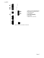
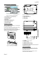
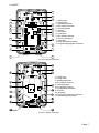
© Cooper Security Ltd. 2011 IN NO EVENT WILL COOPER BE LIABLE FOR ANY SPECIAL, CONSEQUENTIAL , OR INDIRECT LOSS OR DAMAGE, INCIDENTAL DAMAGES, STATUTORY DAMAGES, EXEMPLARY DAMAGES, LOSS OF PROFITS, LOSS OF REVENUE, LOSS OF ANTICIPATED SAVINGS, LOSS OF BUSINESS OR OPPORTUNTIY, LOSS OF GOODWILL OR INJURY TO REPUTATION, LIQUIDATED DAMAGES OR LOSS OF USE, EVEN IF INFORMED OF THE POSSIBILITY OF SUCH DAMAGES. COOPER‟S LIABILITY FOR DAMAGES ARISING OUT OF OR RELATED TO A PRODUCT SHALL IN NO CASE EXCEED THE PURCHASE PRICE OF THE PRODUCT FROM WHICH THE CLAIM ARISES. TO THE EXTENT PERMITTED BY APPLICABLE LAW, THESE LIMITATIONS AND EXCLUSIONS WILL APPLY WHETHER COOPER‟S LIABILITY ARISES FROM BREACH OF CONTRACT, BREACH OF WARRANTY, TORT (INCLUDING BUT NOT LIMITED TO NEGLIGENCE), STRICT LIABILITY, BY OPERATION OF LAW, OR OTHERWISE. Every effort has been made to ensure that the contents of this book are correct. The contents of this book are subject to change without notice. Printed and published in the U.K. This manual applies to the i-on30EX and i-on30EXD control units with version 3 software. For Your Safety This book contains several passages alerting you to potential problems or hazards. Each of these are marked by the words Note, Caution or WARNING.: Note: Describes conditions that may affect the proper functioning of the equipment (but will not damage the equipment). Caution: Describes actions that will physically damage the equipment and prevent its proper function. WARNING: Describes actions that are hazardous to health, or cause injury or death. Please pay particular attention to these marked passages. Other Publications for the i-on30EX: i-onEX Range Administrator and User‟s Guide Instructions for setting and unsetting an alarm system based on the i-on30EX or i-on30EXD. This document also includes detailed notes for the system administrator of an alarm system based on the i-on30EX or i-on30EXD. The following guides are available from the Cooper Security website: www.coopersecurity.co.uk i-onEX Range Engineering Guide A detailed description of the Installer‟s programming options available on the i-on30EX and i-on30EXD. i-on Updater Utility Installation and User Guide This booklet shows you how to install i-on Updater on your PC and use it to update the software on the i-on30EX and ion30EXD control units. Page ii CONTENTS 1. Introduction ..................................... 1 Communications .................................. 1 Level Setting or Partitioned System ........ 1 Installer Programming Interface ............. 2 About this Guide .................................. 2 2. Before You Begin .............................. 2 Preparation ......................................... 2 Siting the Control Unit and Wired Zone Expanders........................................ 2 Siting Keypads ................................. 2 Siting Wireless Zone Expanders .......... 2 Guided Tour ........................................ 3 Opening the Control Unit Case ............ 3 Keypad Controls and Displays ............ 6 Opening the Keypad .......................... 6 Opening Expanders ........................... 6 Power Availability ................................. 8 Bus Cabling Requirements ..................... 8 Cable Type ....................................... 8 Cable Segregation............................. 8 Cable Configuration and Length .......... 9 Bus Termination ............................... 9 Voltage Drop .................................... 9 3. Installation ..................................... 11 Caution: Static Electricity .................. 11 Step 1. Fit the Control Unit Case ........... 11 Fitting ............................................ 11 Step 2. Run Bus Cable ......................... 11 Step 3. Fit and Connect the Keypad(s) ... 11 Siting the Keypad(s) ........................ 11 Fitting ............................................ 11 Keypad Addressing .......................... 11 Backlight Control ............................. 11 Tone Volume ................................... 12 Engineering Keypad ......................... 12 Step 4. Fit and Connect Expanders ........ 12 Connecting an Expander to the Bus .... 12 Addressing Expanders ...................... 12 Expander Loudspeakers .................... 12 Step 5. Connect Control Unit to Mains .... 13 Mains Cabling .................................. 13 Step 6. Connect Wired Zones ................ 13 Four Wire Closed Circuit Connections . 13 Fully Supervised Loop Connections..... 13 Shock Sensors and Roller Shutter Sensors .......................................... 14 Step 7. Connect Wired Outputs ............. 15 Wired External Sounders (Optional) ... 15 Control Unit Wired Outputs ............... 15 Wired Outputs on Expanders ............. 15 Wired External Sounders on Expanders ..................................................... 15 Remote Loudspeakers (Optional) ....... 16 Step 8. Connect the Internal Communicator (i-on30EXD only) ........... 17 Statutory Information....................... 17 Safety Notice ...................................... 18 Connecting the Telephone Line ......... 18 Fit ADSL Filter ................................ 18 Step 9. Fit a Plug-By Communicator ..... 19 Step 10. Fit and Connect Battery .......... 20 Step 11. Initial Power-Up ........................ 20 Leaving the Installer Menu ............... 22 Important! Saving Changes .............. 22 Alerts After Leaving Installer Mode .... 22 Re-Entering the Installer Menu ......... 22 Defaulting Access Codes .................. 23 Restoring Factory Defaults Only ........ 23 Step 12. Commission the System ......... 24 Install Detectors and Other Peripherals .................................................... 24 Program the System ........................ 24 Handover to the User ...................... 24 Installer Menu .................................... 25 4. Maintenance ................................... 27 5. Technical Specification ................... 27 General ............................................. 27 Capacities.......................................... 27 Security ............................................ 28 Power Supply ..................................... 28 EN50131-6 ratings .......................... 28 Electromagnetic Compatibility .............. 29 Outputs ............................................. 29 Sounder Volume Levels (at 1m) ........ 29 Fuses ................................................ 29 Electrical Safety ................................. 29 Other ................................................ 29 Radio Expander and Keypads ............ 29 Compliance Statements ....................... 29 Compatible Equipment ........................ 30 Page iii i-on30EX This page is intentionally blank. Page iv i-on30EX ID. This module also allows remote maintenance. 1. Introduction The i-on30EX is a control unit for a hybrid wired/wirefree alarm system intended for commercial or large domestic use. The control unit comprises a steel case containing the control unit pcb (printed circuit board), power supply and space for a 7Ah backup battery. The control unit pcb provides terminals for a single bus. The bus allows you to connect up to 10 peripheral devices using standard four wire alarm cable. The peripheral devices can be any mixture of keypads, zone expanders (for wireless or wired detectors) or remote power supplies. The control unit pcb also provides a range of connectors for outputs, communicators, and up to 10 FSL (Fully Supervised Loop) or five CC (Closed Circuit) zones. The i-on30EX uses i-kp01 keypads with software revision 2.0 and above. The keypads allow end users to set and unset the system, and the installer to configure the control unit. The keypads also contain integral proximity tag readers, allowing end users to control the system without having to remember access codes. A range of wireless peripherals is available for operation with the wireless expanders. The range includes a door contact/universal transmitter, a passive infra red detector, smoke detector, external siren, 4 button remote control, and remote radio keypad. This control unit is designed and approved to be used as part of a Security Grade 2 system. Communications The i-on30EXD version of the control unit contains a built-in ATS2 communicator, allowing it to comply with EN50131 at Security Grade 2. The i-on30EX also provides sockets for an add-on communication module. The available modules are: i-sd02 (ATS2) A speech dialler and public switched telephone network (PSTN) module that allows the control unit to send recorded speech messages and report alarm information using standard protocols such as Fast Format, SIA and Contact i-dig02 (ATS2) i-gsm02 (ATS2) A PSTN module that allows the control unit to report alarm information using standard protocols such as Fast Format, SIA and Contact ID. This module also allows remote maintenance. A GSM module that allows alarm reporting, speech messaging and SMS text messaging over the mobile phone network. 08750EUR- An Ethernet module that allows 00 alarm reporting and remote maintenance over the internet. (ATS5) 08844EUR- A GPRS module that allows 00 internet protocol access over the mobile phone network. (ATS5) Note: Fitting a plug on module disables the internal communicator. The control unit also provides outputs that can be used to fit a “plug by” communicator. Level Setting or Partitioned System The i-on30EX offers two basic ways of behaving as an alarm system: Part Setting. In a Part Setting system the i-on30EX can set in one of four ways: either Full set or three varieties of Part Set. In Full set the control unit pays attention to all detectors. In each of the three Part Sets the control unit ignores detectors that do not have the appropriate Part Set attribute. Partitioned System. In a Partitioned system the i-on30EX provides the equivalent of 4, smaller, independent alarm systems. Each system is a “Partition” of the i-on30EX. You can allocate any zone to each Partition. Each zone can also belong to more than one Partition. Each Partition can have a Full Set level and one Part Set level. During installation the installer can allocate keypads, sounders or outputs to any of the partitions. For a detailed description of the Installer‟s programming menu please read i-on Range Engineering Guide available from www.coopersecurity.co.uk. Page 1 i-on30EX Installer Programming Interface Once fitted and powered up, you can program the control unit through any compatible keypad connected to the bus cable. The Installer Menu allows you to specify all the operating parameters for an individual installation. If you wish, you can also connect a PC or laptop to the USB port on the control unit pcb and use Cooper Security‟s Downloader software to program the control unit. Note: Some programming options can make the installation non-compliant with EN50131. The relevant options are noted in the “Installer Menu” section of the i-on Range Engineering Guide. About this Guide 2. Before You Begin Preparation Before installation you should carry out a survey of the site. You need to know how many and what kind of detectors will be monitored by the control unit. You also need to assess where any radio expanders must be placed in order to receive radio signals from their detectors successfully. To do this you should conduct signal strength tests. Cooper Security produce the Scantronic 790r hand held signal strength meter and 734r-01 test transmitter for this purpose. Please read the 790r manual for details. Siting the Control Unit and Wired Zone Expanders This guide shows the simple procedure required to physically install the control unit, connect keypads, expanders and power supplies and power up the system for the first time. Do site the unit: When you have completed the physical installation please consult the i-on Range Engineering Guide for details of configuring the system to meet your customer‟s requirements. For your convenience page 25 of this installation guide contains a condensed reference table of the Installer menu. Do NOT site the unit: Upright, battery at the bottom. (This does not apply to the wired zone expander.) Within a protected zone. In the entry or exit zones, or outside the area covered by the alarm system. Next to electronic equipment, particularly computers, photocopiers or other radio equipment, CAT 5 data lines or industrial mains equipment. Siting Keypads If fitting two or more keypads then make sure that you place the keypads more than one metre apart from each other. (At less than one meter separation the proximity tag readers in each keypad will interfere with each other.) Remember not to place keypads on opposite sides of the same wall. Siting Wireless Zone Expanders Do site the unit: Upright. Within a protected zone. As high as possible. However, do make sure that the unit is on a similar level to the transmitters or receivers. More than 10m from another radio expander. Page 2 i-on30EX Do NOT site the unit: In the entry or exit zones, or outside the area covered by the alarm system. Close to or on large metal structures. Closer than one metre to mains wiring, metal water or gas pipes, or other metal surfaces. Lower than two metres from the floor (ideally). Inside metal enclosures. Next to electronic equipment, particularly computers, photocopiers or other radio equipment, CAT 5 data lines or industrial mains equipment. Note: Some window glasses, especially those sold as “insulating” or “energy conserving” may be coated with thin metal or conducting films. These glasses are particularly poor at transmitting radio waves. Guided Tour CAUTION: All printed circuit boards for the i-on30EX, its expanders and keypads have been tested for Electromagnetic Compatibility (EMC). However, when handling the pcbs you must take the standard precautions for handling static sensitive devices. Opening the Control Unit Case To gain access to the interior of the control unit undo the screws at the top and bottom of the lid. Slide the lid out and away from the case. WARNING: When connected to the mains with power applied mains voltages are present on the shrouded heads of the terminal screws of the mains connector. Page 3 i-on30EX 1. Case back. 2. Fixing holes. 3. Cable entry holes for zone and bus wiring. 4. Transformer. 5. Mains fuse and connector block. 6. Mains cable anchor point. 7. Cable entry hole for mains. 8. Printed circuit board (PCB). 9. Cable entry holes for loudspeakers, siren/strobes and communicators Figure 1 Control Unit 1. Connectors for system bus. 2. Zone-, output-, and Aux power connectors. 3. Plug by communicator connectors. 4. Tamper switch. 5. ADSL filter pins. (i-on30EXD only.) 6. On board communicator connections. (i-on30EXD only.) 7. Off-hook LED. (i-on30EXD only.) 8. USB socket (Mini B). 9. Sockets for plug on module. 10.Loudspeaker, Bell and Strobe connectors. 11. Comms activity LED. (i-on30EXD only.) 12. Reset Codes pins. 13. Heartbeat LED. 14. Kickstart pins. 15. Battery connectors. 16. RS485 terminator. 17. Engineering keypad connector. 18. 20Vac connector. Figure 2 Control Unit Printed Circuit Board Page 4 i-on30EX 1. Built-in communicator telephone line connector. (i-on30EXD only.) 2. Siren and strobe. 3. Loudspeaker. 4. Bus cable connector. 5. Output (transistorised). 6. Aux power. 7. Wired zone connectors. Figure 3 Control Unit Main Connectors Page 5 i-on30EX 3 Keypad Controls and Displays 1 1 2 3 2 8 4 5 7 6 Figure 4 Controls and Displays 1. LCD display (2 x 20 characters). 2. Programming keys. 3. Navigation keys 4. Alert LEDs 5. Setting and unsetting keys. 6. Panic Alarm (PA) keys. 7. Number/text keys. 8. Set/Unset LEDs. 3 4 Figure 6 Keypad Rear Housing 1. Central keyhole. 2. Rear tamper shroud. 3. Cable entry. 4. Fixing holes. Opening the Keypad 2 Note: For EN50131-3:2009, 8.7 the keypad is a type B ACE, fixed. 3 To open the keypad first gently prise off the trim on the front and remove the two screws. Next, carefully lever the front of the keypad (containing the pcb and display) away from the keypad rear housing. 1 4 5 6 1 ET B A 12V 0 V 2 4 BACKLIGHT ABCD-ON ON BRIGHT Figure 7 Keypad PCB 4 3 Figure 5 Opening the Keypad 1. Sounder. 2. Sounder volume control. 3. Tamper switch. 4. Jumpers for LED function: 5. RS485 termination jumper 6. Connector for control unit (note that the ET terminals are inactive). Opening Expanders To open any of the expander cases undo the single screw and lift the top of the lid away from the case. Figures 8 and 9 show the interior of the wired and radio expanders. Page 6 i-on30EX 1 5 1 13 7 8 1 1 6 7 1 9 10 10 12 11 2 2 3 1. Cable entry. 2. Fixing holes. 3. Addressing button. 4. Bus cable connector. 5. Central keyhole. 6. Outputs. 7. Aux power. 8. Lid tamper. 9. Bus address display. 10. Zone connectors. 11. Sounder. 12. Bus termination jumper. 13. Engineering keypad connector 4 Figure 8 Wired Expander 1. Cable entry. 2. Fixing holes. 3. Addressing button. 4. Bus cable connector. 5. Central keyhole. 6. Bus address display. 7. Loudspeaker terminals. 8. Sounder. 9. Lid tamper. 10. Engineering keypad connector 11. Bus termination jumper. Figure 9 Radio Expander Page 7 i-on30EX Power Availability Before connecting any external devices to the control unit, you must make sure that the control unit can provide sufficient current to power the system during a mains failure for the time required to meet the appropriate standard. EN51031-1 Grade 2 and PD6662 Grade 2 both require 12 hours standby time. Note: When calculating the average load during the standby time period you must allow for at least two periods in alarm. To take the worst case these two periods of alarm should each be 15 minutes long, the maximum permitted in EN50131-1 section 8.6. The amount of current available from the control unit depends on the size of battery fitted and its health. The current taken by the control unit pcb, communicator and keypads is given in Technical Specifications – EN50131-6 Ratings on page 28. The following calculation shows a simplified example: in an alarm system with an ion30EX control unit, two i-kp01 keypads, and 20 wired PIRs the system takes the following total quiescent current: Device Current Control unit PCB 100mA 15 x PIRs at 15mA each 225mA 1 x (wired expander) 20mA 2 x i-kp01 at 30mA each 60mA (backlights off) Siren (quiescent) 25mA Total 430mA During an alarm, these figures become: Device Current Control unit PCB 120mA 15 x PIRs at 15mA each 225mA 1 x (wired expander) 20mA 2 x i-kp01 at 60mA each 120mA (backlights off) Siren (in alarm) 400mA Total 885mA The total amp hours required = (0.430 A x 11.5h) + (0.885A x 0.5h) = 5.39Ah One new, fully charged, 7Ah battery can provide the charge required by the example system and would meet the Grade 2 requirements. Page 8 Note: All current drawn from the Aux terminals (12V) must be included in the overall calculation. CAUTION: Ensure that the system does not demand more than the maximum current available from the control unit during an alarm, see page 28. Bus Cabling Requirements Cable Type In general, the control unit requires standard 7/0.2 un-screened four core alarm cable for wiring the bus. For maximum performance in harsh environments use twisted pair screened cable with a characteristic impedance of 100-120ohms eg: Belden 8132 or cable designed for RS485. Use one pair for data lines A and B. Use the other pair for 12V and 0V. For optimum performance the voltage at the keypads and expanders should be greater than 12V. Screened cable may prove necessary if the installation site has equipment that produces high levels of R.F. (Radio Frequencies). For example, welding equipment is known to produce a large amount of radio interference. If screened cable is required, you should keep to the following guidelines: 1. Avoid earth loops by connecting the screen on the cable to mains earth at the control unit but not at the keypad or expander. 2. The continuity of the cable screen is most important and screens MUST be continuous along the full length of the cable. 3. Where the cable enters any metal enclosure, ensure the screen is isolated from the case. Cable Segregation Segregate the bus cabling from any other wiring, such as mains supply cables, telephone cables, computer network cables and R.F. cables. Use cable ties to keep cables separated. Keep the bus cable clear of cables supplying sounders, extension loudspeakers or any other high current devices. i-on30EX Cable Configuration and Length You can connect up to 10 devices to the control unit bus. You may connect the devices either in daisy chain (serially), or in star (parallel) configuration at the control unit connector. Figure 10 Bus Wiring Configurations For star configurations the cable length from control unit to the most distant bus device should be kept short, and should not exceed 100m. There should be no more than four arms in the star. For a daisy chain configuration the total cable length should not exceed 1,000m. Bus Termination The i-on30EX bus uses the RS485 interface. Because of this the ends of the line in some configurations may be terminated to improve performance in electrically noisy environments or where there are long cable runs. The control unit. expanders and keypads have a termination link on their PCBs (see 16 in Fig 2 for the control unit, 5 in Fig 7 for the keypad, 12 in Fig 8 for the wired expander and 11 in Fig 9 for the radio expander). Fitting a jumper to the pins adds a termination to the cable. In a daisy chain configuration fit the termination jumpers in the devices at each end of the chain (see Fig 10 ). In a star configuration: If there are only two arms on the star then this is the same as a daisy chain configuration (see “Daisy Chain 1” in Figure 10). If required fit the termination jumper at the devices on the end of each arm. If there are more than two arms AND two cables are long while the remaining cables are short (less than 10m) then it is possible to terminate at the two devices on the ends of the long cables. If there are more than two arms BUT each cable is more than 10m then DO NOT fit the termination jumpers on any of the devices. Voltage Drop In order for the system to work correctly, the voltage at each device must NOT drop below 10.5V even when running on the standby battery. Cooper Security recommend that the voltage at each device should stay above 12V. Standard 7/0.2 alarm cable has a resistance of 8 Ohms per 100m per core. The voltage drop is calculated using the following formula: V Drop = Current drawn x cable length x 0.08 x 2. Table 1 shows the voltage drop against the current drawn and cable length. The shaded area shows where the voltage drop would cause the bus voltage to fall from 13.8V to below 12.0V when using a single core. Page 9 i-on30EX Table 1. Voltage Drop Current Drawn 60mA 80mA 100mA 120mA 140mA 160mA 180mA 200mA 220mA 240mA 260mA 280mA 300mA 320mA 340mA 360mA 380mA 400mA Cable Length (Standard 7/0.2 alarm cable) 10m 0.10V 0.13V 0.16V 0.19V 0.22V 0.26V 0.29V 0.32V 0.35V 0.38V 0.42V 0.45V 0.48V 0.51V 0.54V 0.58V 0.61V 0.64V 20m 0.19V 0.26V 0.32V 0.38V 0.45V 0.51V 0.58V 0.64V 0.70V 0.79V 0.83V 0.90V 0.96V 1.02V 1.09V 1.15V 1.22V 1.28V 30m 0.29V 0.38V 0.48V 0.58V 0.67V 0.77V 0.86V 0.96V 1.06V 1.15V 1.25V 1.34V 1.44V 1.55V 1.63V 1.73V 1.82V 1.92V 40m 0.38V 0.51V 0.64V 0.79V 0.90V 1.02V 1.15V 1.28V 1.41V 1.54V 1.66V 1.79V 1.92V 2.05V 2.18V 2.30V 2.43V 2.56V Reducing Voltage Drop - Method 1: Double up the supply connections (12V and 0V), which will halve the resistance on each core and therefore halve the voltage drop. When using Table 1 to calculate the expected voltage drop, simply divide the voltage drop for a single core by two. Reducing Voltage Drop - Method 2: Supply the detection devices from the Aux output on separate cores. This is the preferred method of reducing voltage drop as detectors generally operate at lower voltages (9.5V). When using this method, the bus cable must have two spare cores. 50m 0.48V 0.64V 0.80V 0.96V 1.12V 1.28V 1.44V 1.60V 1.76V 1.92V 2.08V 2.24V 2.40V 2.56V 2.72V 2.88V 3.04V 3.20V 60m 0.58V 0.79V 0.96V 1.15V 1.34V 1.54V 1.73V 1.92V 2.11V 2.30V 2.50V 2.69V 2.88V 3.07V 3.26V 3.46V 3.65V 3.84V 70m 0.67V 0.90V 1.12V 1.34V 1.57V 1.79V 2.02V 2.24V 2.46V 2.69V 2.91V 3.14V 3.36V 3.58V 3.81V 4.03V 4.26V 4.48V 80m 0.77V 1.02V 1.28V 1.54V 1.79V 2.05V 2.30V 2.56V 2.82V 3.07V 3.33V 3.58V 3.84V 4.10V 4.35V 4.61V 4.86V 5.12V 100m 0.96V 1.28V 1.60V 1.92V 2.24V 2.56V 2.88V 3.20V 3.52V 3.84V 4.16V 4.48V 4.80V 5.12V 5.44V 5.76V 6.08V 6.40V Remote Power Supplies When you cannot reduce voltage drops by method 1 or 2, or the demand on the control unit power supply exceeds its capacity (see Technical Specifications – page 28), you should install one or more remote power supplies. The supply must have a "floating zero rail" if connected to the bus, otherwise an earth fault will occur. Cooper Security recommend the EXP-PSU. When installing a remote power supply, fit it close to the equipment it is powering. Figure 11 shows the recommended method of connecting a remote power supply. Figure 11. Connecting Remote Power Supply Units Page 10 90m 0.86V 1.15V 1.44V 1.74V 2.02V 2.30V 2.59V 2.88V 3.17V 3.46V 3.74V 4.03V 4.32V 4.61V 4.90V 5.18V 5.47V 5.76V i-on30EX 3. Installation Where the cable run from the control unit will be longer than 100m (see Cable Configuration and Length). Note: The installation steps listed below assume that you have already decided on the required number and location for all keypads, expanders and power supplies. Note: Do not site two or more keypads closer than one metre together, otherwise their prox readers will interfere and be unable to read tags. Caution: Static Electricity Fitting Like many other electronic products, the control unit, keypads and expanders contain components that are sensitive to static electricity. Try not handle their PCBs directly. If you must handle a PCB, take the standard precautions against damage by static electricity. Use No8/M4 25mm countersunk screws in at least three fixing holes when mounting the back of the keypad on the wall. Step 1. Fit the Control Unit Case Fitting To prevent access to the inside of the control unit through the holes in the rear of the case you must mount the control unit on a wall or other flat surface. Mount the case vertically, as shown in Figure 1. Use all three fixing holes. Use No8/M4 dome or pan head screws at least 30mm long, inserted into wall anchors appropriate for the type of wall. Figure 1 shows the fixing holes and cable entries. Figure 12 Screw Keypad Back Box to Wall Connection Figure 13 shows the wiring connections at the keypad and control unit. Protect the unit from dust and drilling debris when drilling the fixing holes. Step 2. Run Bus Cable Please read “Cabling Requirements on page 8. Step 3. Fit and Connect the Keypad(s) Figure 13 Connecting a Keypad to the Bus Siting the Keypad(s) Keypad Addressing Do site the keypad(s): The control unit assigns addresses to all devices connected to the bus cable. You must start this process off once all bus devices are connected, during the initial power up. See page 20 for instructions. Within the area protected by the alarm system. At a convenient height and location for the user. Out of sight of potential intruders. Do NOT site the keypad(s): Next to electronic equipment, particularly computers, photocopiers or other radio equipment, CAT 5 data lines or industrial mains equipment. Backlight Control You can control the appearance of the keypad backlights and set/unset LEDs by fitting links over the appropriate jumpers on the keypad pcb (see Figure 7 on page 6 for the position of the jumpers). Page 11 i-on30EX The jumpers have the following functions: ABCD-ON ABCD-ON The set/unset LEDs are disabled. ABCD-ON ABCD-ON ABCD-ON ON BLABCD-ON The set/unset LEDs shows the setting ABCD-ON BRIGHT status of ON the system. (Full set is the left BL BRIGHT hand LED.) ABCD-ON ABCD-ON ON BL ON BL BRIGHT BRIGHT ON BL BRIGHT ABCD-ON The key backlights are disabled. They ON BL glow will briefly for five seconds when a ON ON BL BRIGHT BL user presses a key. BRIGHT BRIGHT ON BRIGHT ON BRIGHT ON BL BRIGHT ON BL BRIGHT BL on Figure 2) or any of the expanders (see 13 on Figure 8 or 10 on Figure 9). An Engineering Keypad does not need to be addressed, and will always be recognised by the control unit. You can use an Engineering Keypad to program the system without being tied to any of the installed keypads. If you wish to move an Engineering keypad from one connection point to another then you can do so without removing power from the system. Step 4. Fit and Connect Expanders Both wired and radio expanders are supplied in the same plastic case. Use M4 25mm countersunk screws in at least three fixing holes when mounting the back of the case on the wall. See Figures 8 or 9 for the position of fixing holes and cable entries. Connecting an Expander to the Bus BL Both wired and radio expanders provide a connector for the bus at the bottom of their pcbs (item 4 on Figures 8 and 9 ) . ONbacklights glow all the time at BL The key BRIGHT normal intensity. BL ON BRIGHT BL ON BRIGHT The keypad backlights glow all the time, extra bright. Tone Volume To alter the volume of non-alarm tones from the keypad adjust the keypad sounder volume control (2 in Fig 7): Louder Note: This control changes the volume of non-alarm tones (for example Exit/Entry tone). The volume of alarm tones is fixed. Softer Engineering Keypad An Engineering Keypad is a modified i-kp01 that can be plugged into a dedicated connector on the control unit pcb (see 17 Page 12 Figure 14 Wiring Expanders Addressing Expanders The control unit assigns addresses to all devices connected to the bus cable. You must start this process off once all bus devices are connected, during the initial power up. See page 20 for instructions. Expander Loudspeakers During normal operation loudspeakers on expanders repeat setting and entry tones for the partition that the expander is allocated to. During an alarm the loudspeakers repeat alarm tones. i-on30EX Each loudspeaker draws up to 280mA in operation. if there is more than one expander loudspeaker then the bus may not be able to supply sufficient current during an alarm. different on the expander compared to the control unit. Step 5. Connect Control Unit to Mains WARNING: ENSURE THAT THE MAINS SUPPLY IS DISCONNECTED AND ISOLATED BEFORE MAKING ANY MAINS CONNECTIONS. All mains electrical connections must be carried out by a qualified electrician and must comply with the current local regulations (e.g. IEE). Mains Cabling Note: To avoid mains interference, the mains cable must enter the control unit through its own cable entry hole (7 in Fig 1) and must not be mixed with other cables. Figure 16 Control Unit CCL Zone Wiring Alarm Zone 0 Tamper Zone 0 Z8 Z1 Wired Expander Z7 Z2 Tamper Zone 1 Z4 Alarm Zone 2 Z5 Z3 Z6 Alarm Zone 1 Z9 Z0 Mains Connection Figure 15 shows the mains connection. Connect to a suitable supply using a double pole disconnect device in accordance with EN60950-1. Caution: Do not apply power at this point. Anchor the mains cable with a strain-relief tie. There is a eye located near the mains cable entry hole for this purpose (6 in Fig 1). Tamper Zone 2 Figure 17 Wired Expander CCL Zone Wiring Fully Supervised Loop Connections Figure 15 Mains Connection Step 6. Connect Wired Zones Figure 18 shows the wiring connections for FSL zones on the control unit. Note that the resistance values shown are examples. The control unit and the wired expander connectors can be used for either four wire Closed Circuit Loop (CCL) detectors, or two wire Fully Supervised Loop (FSL) detectors. Four Wire Closed Circuit Connections Figure 16 shows the wiring for CCL zones on the control unit. Figure 17 shows the wiring for CCL zones on the wired expander. Note that the connections are Page 13 i-on30EX When programming select the FSL resistor values for the control unit in Installer Menu System Options - Wired Zone Type. To select the resistor values for a wired expander use Installer Menu – Detectors Devices – Wired Expanders - Edit Expander. If you wish to connect two or more detectors to a FSL zone, Figure 20 shows the connections required. Figure 20 Wiring Two Detectors per Zone FSL. Figure 18 FSL Zone Wiring – Control Unit Figure 19 shows the wiring connections for FSL zones on the expander. Note that the connections are different on the expander compared with the control unit. Figure 21 shows an example of wiring double doors with two door contacts to one FSL zone. Each door contact is a reed switch, connected between the outer terminals. The inner (shaded) terminal is not connected, and provides a spare terminal. Z0 Spare Blue Z1 To zone contacts Yellow 2K2 EOL Red Z2 Wired Expander Z3 4K7 Z4 100 Ohms 4K7 Alarm contacts Zone 1 Zone 0 Black Figure 21 Example: Wiring Two Door Contacts to One FSL Zone. 2K2 EOL Tamper contacts 4K7 Alarm contacts Figure 22 shows an example of wiring a trouble/masking output using the “3resistor method”. Note that you must use 2k2 and 4k7 resistors as shown. Other values will not work (See System Options – Masking in the i-on Range Engineering Guide). 2K2 EOL Tamper contacts Figure 19 FSL Zone Wiring - Expander The allowed values for Alarm Contact/End of Line resistors are: 4k7/2k2. 1k0/1k0, 2k2/2k2, or 4k7/4k7. Note: Use the same pair of values for ALL FSL wired circuits on the control unit. A wired expander can use a different pair of resistor values, but ALL circuits on an expander must have the SAME values. Page 14 Figure 22 Example: Wiring a Trouble/Masking Zone, 3 Resistor Method. Shock Sensors and Roller Shutter Sensors You must connect roller shutter detectors and shock sensors to the zone terminals on the control unit. Do not connect them to wired expanders. In addition, you must i-on30EX program the control unit zones‟ wiring type as 2-wire FSL, with 2k2/4k7 resistors. See i-on Range Engineering Guide part number 12098019 for more details. Step 7. Connect Wired Outputs Wired External Sounders (Optional) Wired external sounders differ in their methods of connection. Figure 23 shows an example of a general method of using the outputs to connect a wired sounder. Note: If you do not wish to connect a wired external sounder then make sure you link TR to 0V. This prevents the control unit reporting Bell Tamper unnecessarily. Wired Outputs on Expanders Each EXP-W10 wired expander provides connections for up to four transistor driven outputs. By default the outputs are 0V when active, +12V when inactive. If you wish to reverse the polarity of these two outputs see Changing the Polarity of a Wired Output in the i-on Range Engineering Guide. Figure 24 shows an example of using an expander output to drive an LED. 16 Ohm minimum Typical loudspeake r for example 09040 1K0 Resistor LED (Light Emitting Diode) 0V 12V AUX Out 1 OUTPUTS 2 3 4 - LS + Figure 24 Using Wired Expander Outputs. Wired External Sounders on Expanders Figure 23 Connecting Wired Peripherals Control Unit Wired Outputs The control unit pcb provides one connector for wired outputs. Outputs 1 is driven by a transistor, and is capable of sinking a maximum 500mA when active. By default outputs 1 is 0V when active, +12V when inactive. If you wish to reverse the polarity of this output see Changing the Polarity of a Wired Output in the i-on Range Engineering Guide. Figure 23 shows an example of using the wired outputs to drive an indicator LED. Figure 25 Wiring External Sounder to Expander Page 15 i-on30EX Figure 25 shows a general method of using the outputs on a wired expander to connect a wired external sounder. Connect the tamper wiring to an unused zone connection on the expander. For 4wire CC zones use the alarm contacts only and link the tamper contacts together with a short length of wire. For FSL wiring, connect a 2k2 resistor in series with the link from –TR on the external sounder to the left hand terminal of the zone connector see Figure 27. In the Installer Menu, program the zone with a type of “Tamper”. Program the outputs used to trigger the siren and strobe with the appropriate output types. See the i-onEX Range Engineering Guide for more details. If the external sounder provides a single – TR connection, then the exact wiring depends on whether the expander is programmed as FSL or 4 wire CC zone wiring. For CC wiring connect –TR on the external sounder to the left hand terminal of the pair on the zone that you are using to report the tamper, see Figure 26. Fit a short wire link to the zones tamper terminals. Figure 27 Wiring –TR from External Sounder to a FSL Zone on the Expander. Remote Loudspeakers (Optional) If you wish to add a 16 Ohm wired Loudspeaker unit, then connect it as shown in Figures 23 or 24. The control unit provides connections for one loudspeaker. Expanders provide connections for one loudspeaker each. Do not connect another loudspeaker in parallel. You may connect another loudspeaker in series, but this will decrease the maximum volume from the speakers. Note: Loudspeakers are not warning devices as described by EN50131-4. Although loudspeakers may mimic alarm tones, they also give alert tones and other progress tones when setting and unsetting the alarm system. Figure 26 Wiring –TR from External Sounder to a – 4 wire CC Zone on the Expander. Page 16 i-on30EX Step 8. Connect the Internal Communicator (i-on30EXD only) The i-on30EXD version of the control unit has an internal communicator on its main PCB. This is an auto-dialling modem. If necessary, a standalone communication device can be connected through a wiring harness to interface pins on the main PCB (this is known as a plug-by communicator, see page 19). The communicator can be used for: • Transmitting alarm signals to alarm receiving equipment at a central monitoring station using Scancom Fast Format, Scancom SIA (Security Industry Association) or Contact ID. • Connecting to a PC based at a remote engineering centre. Using Scantronic Downloader software, the remote PC can upload and download system parameters (including the event log and diagnostics), set and unset the alarm system, and carry out other special functions. Telephone Line Ideally, the internal communicator should be connected to an ex-directory line used exclusively for alarm communications. Line Monitoring for the Internal Communicator The control unit provides a line monitoring function to check that a telephone line connected directly to the control unit is working, and to indicate a line failure if it is not. While enabled, this function continually checks the line voltage to ensure that the line is connected. If it detects a failure, the system gives the Line Fault Response selected in the Installer Menu. Test Calls The control unit can be programmed to make test report calls to an ARC. "Static" test calls can be programmed to occur at set times or intervals. "Dynamic" test calls occur 24 hours after the last call made by the unit. See the i-on Range Engineering Guide for details on how to program these functions. Statutory Information Applications The built-in communicator is suitable for connection to the following types of networks: (a) Direct exchange lines (PSTN) supporting DTMF (tone) dialling. (b) PABX exchanges (with or without secondary proceed indication). Note: The built-in communicator is not suitable for connection as an extension to a pay-phone or to 1 + 1 carrier systems. Approval The built-in communicator is manufactured to meet all European Economic Area telecommunication networks requirements. However, due to differences between the individual PSTNs provided in different countries, the approval does not, of itself, give an unconditional assurance of successful operation on every PSTN network termination point. The built-in communicator has been approved for the following usage: (a) Automatic call initialisation. (b) Operation in absence of indication to proceed. (c) Automatic dialling. (d) Modem. (e) Serial connection. (f) Multiple repeat attempts. (g) Line status monitoring. Usage other than approved usage or failure to comply with the installation and programming instructions may invalidate any approval given to the apparatus if, as a result, the apparatus ceases to comply with the standards against which approval was granted. Note the approval label on the main PCB. In the event of problems you should contact your equipment supplier in the first instance. Ringer Equivalence Number The Ringer Equivalence Number (REN) of the built-in communicator is 1. As a guide to the number of items that can be simultaneously connected to an exclusive line, the sum of the REN values should not exceed 4. A standard telephone (as provided, for example, by BT in the UK) has a REN value of 1. Page 17 i-on30EX Safety Notice Figure 28 identifies connectors for Safety Extra-Low Voltage (SELV) and Telecommunications Network Voltage (TNV) circuits on the control unit's main PCB. These terms are used in accordance with the definitions in Safety Standard EN60 950. The Installer must ensure that TNV terminals are connected only to other circuits designated as TNV circuits (for example, the PTSN) and that SELV terminals are connected only to other circuits designated as SELV circuits. Strict adherence to the installation instructions will ensure that the equipment continues to comply with the safety regulations to which it was approved. Example – connecting a line in the UK: The internal communicator must be connected to the telephone network by: a) If the wiring is owned by British Telecom: British Telecom. b) If the wiring is not owned by British Telecom, one of: (i) British Telecom. (ii) The authorised maintainer. (iii) A professional Installer, after 14 days written notice to the authorised maintainer. To connect the telephone line (see Figure 29): (i) Using a two-core telephone cable, strip off 5mm and feed the cable through one of the entries (marked “10” in Fig. 2) in the rear of the control unit. Connect the two cores to terminals A and B on the main PCB. (ii) Connect the other end of the two cores to the corresponding terminals on the BT master box. Figure 29 Connecting the Internal Communicator Fit ADSL Filter TNV - Telephone line connector. SELV – All other connectors. Figure 28 SELV and TNV connectors Connecting the Telephone Line Connecting the telephone line directly to the terminals on the internal communicator, or indirectly through other apparatus, can produce hazardous conditions on the telephone network. Always seek advice from a competent telephone engineer if in any doubt about connecting to these terminals. Page 18 If the telephone line is being shared by a broadband service then you should fit a broadband filter to the line. Cooper Security provide the ADSL01 filter that plugs onto pins provided for the purpose on the main circuit board of the control unit (see 5 on Figure 2). Figure 30 shows how to fit the filter. i-on30EX Figure 31 Plug-By Communicator Wiring Note: Comms O/P4 will be active when the system is unset. This is normal. To fit a communicator, follow the instructions below. Caution: Follow the instructions in the order shown, or you may damage the control unit and/or communicator. Figure 30 Fitting the ADSL01 Filter. Note: If you remove the ADSL01 filter then re-fit the jumpers to the outermost pairs of pins. If you fail to re-fit the jumpers the internal communicator will not connect to the phone line. Step 9. Fit a Plug-By Communicator The control unit can be connected to a separate communicator or speech dialler (for example, the Scantronic 8400, 8440, 660 or RedCare STU). Figure 31 shows the connections provided by the communications wiring harness. Note that the output types shown in Figure 31 are the Factory default types. See the i-on Range Engineering Guide for details on how to change the defaults. 1. Disconnect mains power from the control unit, remove the case lid, and disconnect the battery (if the system has already been installed). 2. Make any necessary connections from the communicator to the communication wiring harness. The default is a 12V positive voltage when the output is inactive. Refer to the next section if you are using a dual-path communicator. 3. Plug the Communication Wiring Harness onto the communications connector on the main PCB. If the system has already been installed: 4. Re-connect the battery. 5. Fit the case lid. 6. Apply mains power. 7. Test communicator operation. Note: You will need to speak to the ARC in order to confirm that the communicator has worked correctly. Page 19 i-on30EX Line Monitoring for a Dual-Path Communicator If a standalone dual-path (landline and mobile) communication device, such as a RedCARE STU, is connected to the plug-by connector, you need to do the following to obtain correct line fault reporting that complies with BSIA Form No.175, April 2005 (this is not necessary if you are using a plug-on module): 1. Reprogram one of the plug by outputs to type “ATS Test” and wire that output to the ATS Test input of the communicator. 2. Wire the Line Fault output of the communicator to the Line Fault input of the plug-by connector. The communicator must provide +12Vdc to indicate a line fault (for example, if the Line Fault output at the communicator uses a relay, connect the common terminal of the relay to +12Vdc and the normally-open terminal to the Line Fault input of the plug-by connector). The control unit will generate an "ATE L.F. Single" alert if only one of the networks is not available, or "ATE L.F. All" if both networks are not available. Step 10. Fit and Connect Battery Fit a 7Ah Lead Acid battery into the battery compartment in the bottom of the control unit (see Figure 32). See page 8 for example calculations of battery requirements. Connect the battery leads, red to the positive, black to the negative terminals of the battery. Connect the other ends of the leads to BATT (15 on Figure 2). Note: Connecting the battery without mains power will not start the system. (See “Programming Before Installation” in the ion Range Engineering Guide.) Step 11. Initial Power-Up Please see the i-on Range Engineering Guide for an explanation of bus addressing. WARNING: During initial power-up all the keypad sounders, internal loudspeakers and wired sirens MAY give an alarm tone. If you are working at the top of a ladder make sure that the sudden noise does not startle you and cause a fall. 1. Apply mains power to the control unit. The keypads and internal sounder may give an alarm tone. The heartbeat LED on the control unit pcb (see 13 on Fig 2) starts flashing. The navigation keys on any attached keypad start flashing. All connected keypads briefly show the software revision of the keypad itself, followed by the words “Please wait...” for several seconds while the control unit scans the bus. When the control unit has finished scanning the bus the keypads show: 2. Press and hold keys A and on the keypad that you wish to use for initial programming. NOTE: Hold the keys down for at least three seconds. After a short pause the keypad gives a confirmation tone and the display initially shows the bus address of the keypad. It should be “b1-d51” (bus 1 device 51) if there are no other addressed keypads connected to the bus. (Keypads take bus device addresses 51 upwards.) The keypad display then shows: 3. Press or followed by to select the language you want. (In the ion30EX English is the only language available.) From this point on, the display operates in the selected language. If you want to change the language later use Installer Menu - System Options - Language. The display shows: Figure 32 Fitting the Batteries Page 20 i-on30EX 4. Press or to show other countries, for example 5. Press to select the country you want. The display shows: 6. Press A or B to select either a Partitioned system or a Part Setting system. 7. Press or to show the range of zone wiring types available, for example: 8. Press to select the wiring type you intend to use for the wired zones. Note: This initial choice fixes the wiring type for the control unit and any attached wired expanders. If you wish to use a different wiring type on the expanders then use Installer Menu – Detectors/Devices – Wired Expander after the initial power up to change the wiring type for each expander. The display shows: Note that the alert LEDs round the navigation key glow red. This is because the control unit lid is off and the tamper is active. 9. Press . The display shows: 10. Press . The display shows: 11. Press . The display shows: 12. Press . The display shows: At this point you must make the control unit allocate an address to each of the connected bus devices, as follows: 13. Go to each bus device. You can visit the devices in any order, but if you visit them in the order you want their address numbers to appear then it will make subsequent programming easier. The control unit assigns the next free bus address to a bus device when you make the device request a bus address. For keypads: Hold down keys A and until the display shows a bus and device number. For example: For expanders: Open the lid (to make sure that the tamper switch opens) and hold down the addressing button (item 3 on Figures 8 and 9 ). When you do so the control unit assigns the next free address to that expander. The expander gives a double “beep” confirmation tone and shows its assigned address on the two-digit LED display. Replace the lid. NOTE: DO NOT request a bus address from two different devices at the same time. 14. When you have visited all the connected bus devices, go back to the keypad and press . The display shows: 15. Replace the control unit lid, making sure that the lid tamper closes. 16. At this point you should leave the Installer Menu to save the changes you have made, see overleaf. Note: To set the time and date use Installer Menu - System Options – Set Date & Time. See i-on Range Engineering Guide for more information. Diagnostic LED on Expanders You may notice the DIAGNOSTIC LED flashing on an expander PCB. The LED gives one, two, three or four flashes a second. Each of these sequences has the following meaning. No. Flashes Meaning One Communication with control unit over bus is OK Two No communication over the bus in the last 10 seconds. Three No bus address allocated to expander Four No poll request received from control unit in the last minute. Page 21 i-on30EX Leaving the Installer Menu If you wish to leave the Installer Menu at any time. 1. Press until the display shows the words:. 2. Press to leave Installer menu. (Press if you do not want to leave the menu.) The display shows: After a delay of anywhere between a few seconds to a few 10s of seconds (depending on the number of expanders fitted) the display shows the time and date: The system is ready for further programming. 3. If the control unit finds a device missing, or one with an address that has not been added using the Installer Menu then the display shows, for example: The top line of the display shows the number of new devices found, and the number of existing devices missing (lost). The bottom line of the display shows the first in the list of found and lost devices. Press to see any other items in the list. 4. Either: Press to go back into Installer Menu (so that you can go and check that all the bus devices you have installed are connected, powered up and addressed correctly). Note: To check an expander address remove the expander’s lid and briefly press the addressing button. The two digit display will show the bus address for a few seconds. OR: Press to make the control unit update its internal record of devices attached to the bus. The display shows: 5. Press to accept the change to the bus. (You can still press to return to the installer menu if you do not want to change the number of devices on the bus.) Page 22 Note: If you attempt to leave the Installer Menu when a detector tamper is active then the keypad displays a fault message telling you which detector is causing the problem. Press to return to the Installer Menu. You must either close the detector tamper or delete it from the system before you can leave the Installer Menu. Important! Saving Changes When you make changes to the Installer Menu the control unit holds those changes in temporary memory until you leave the Installer Menu. As you leave the Installer Menu the control unit writes those changes into a permanent store. If you remove all power BEFORE you leave the Installer Menu then the control unit will lose your changes. Note that this does not apply if you restore Factory Defaults, that change takes place immediately. Alerts After Leaving Installer Mode Once you have left the Installer Menu you may see the red LEDs around the navigation key glowing. A common cause of this alert is that there is no telephone line connected to the built-in communicator. If you do not intend to use the built-in communicator then re-enter the Installer Menu and disable the communicator by setting Communications – ARC Reporting – Call Mode to “Disabled”. See the i-on Range Engineering Guide for more information. Re-Entering the Installer Menu When you enter the Installer Menu from a keypad, the alarm system is effectively disabled. While the system is in Installer Menu: Any other user trying to set the system from a keypad will see the message “Installer on Site”. All PAs (including radio PAs), fire alarm zones, 24 hour zones and tampers are disabled. If you have logged into the system from a PC then the alarm system is active. If you need to re-enter the Installer Menu: 1. Make sure the system is unset and showing the standby screen (time and date). 2. Key in the Installer access code. The default Installer access code is “7890”. i-on30EX As you start to key in the code the display shows: When you key in the last digit of the Installer access code the display shows: Note: You will see this screen the first time you enter the Installer menu on a new control unit, or if you have restored Factory Defaults. 3. Key in the default user code (see Note below). The default user access code is “1234”. The display shows: 4. Press or to display more items from the menu. Each item appears on the bottom line of the display in turn, for example: 5. Press to select that item of the menu. The option you selected now appears on the top line. If there are any suboptions for that selection, then the first of them appears on the bottom line, for example: You can press or to display the other sub-options. Note: If you key in an access code incorrectly, the display shows four “stars”. Key in the code again. If you key in a total of ten incorrect codes then the system locks you out for 90 seconds. Defaulting Access Codes If the User 1 and/or Installer codes are lost then you must restore all user codes to their factory defaults. 1. If possible, enter the Installer menu. Note: If you cannot enter Installer Menu then the control unit will start a tamper alarm when you open the control unit lid. 2. Remove mains power, then open the case and disconnect the battery. Note: This procedure will not work if the control unit lid tamper remains closed. 3. Identify the Reset Codes pins on the main PCB (see item 12 in Figure 2). 4. Short the Reset Codes pins together using a screwdriver or jumper link. (Keep the short on until step 6.) 5. Apply mains power. The control unit loads the factory default access codes: User 1=1234, Installer=7890. After a short pause the system starts a a tamper alarm and the display shows the words “Please wait...”. The red LEDs glow to show an alert that the control unit lid is open. 6. Remove the short from the Reset Codes pins. 7. Reconnect the battery. 8. Close the control unit lid (to restore the tamper switch). The display shows the time and date, for example: 9. Key-in the default user 01 code to silence the sounders. The display shows: 10. Enter Installer Menu and then leave it again. The LEDs around the navigation key should now be green. If they glow red then there may be an alert for a missing battery that needs acknowledgement. To force the control unit to check the battery: 11. Press , key in 1234, press again. The navigation key LEDs should now glow green. Note: The log is protected and cannot be erased by the Installer. Restoring Factory Defaults Only If you wish to restore all factory default options, without defaulting the user and installer access codes then: 1. From the Installer Menu select System Options – Restore Defaults – Factory Defaults. The display shows: 2. EITHER: Press to go back to the Installer Menu without changing defaults. OR: Press to load defaults. If you press the display shows: Page 23 i-on30EX 3. Press A or B to select the desired mode. The display shows: 4. Press or to display the desired wiring type on the bottom line of the display and then press to select it. The system loads all defaults except for Access Codes and the Log. The display briefly shows: Followed by: 5. Press until the display shows: 6. Press . The display shows: The control unit scans the bus to see what devices are attached and powered up. After several seconds (depending on the number of devices connected to the bus) the display shows, for example: The top line of the display shows the number of new devices found. Because you have restored factory defaults the control unit has erased its internal list of bus devices and the display will not show any devices as missing. (If a device is attached to the bus but not powered up then the control unit will not detect it.) The bottom line of the display shows the first in the list of found devices. Press to see any other items in the list. 7. Press . The display shows: 8. Press . The keypad sounder gives “dee dah” confirmation tone and the display shows the time and date, for example: The control unit has saved all the changes you have made. Page 24 Step 12. Commission the System Install Detectors and Other Peripherals 1. Use the Installer Menu to teach the system the identity of any radio detectors or other peripherals. (Note that you must have a radio expander already connected and installed on the bus to do this.) See the installation instructions supplied with each detector or peripheral. 2. Install detectors and peripherals at their selected locations. 3. Use the Installer Menu – Test option to: a) carry out a walk test of the detectors. b) test the operation of any other peripherals. Program the System Program the system to suit user requirements. Page 25 is a summary of the Installer Menu on the i-on30EX. Please see the i-on Range Engineering Guide for a more detailed description. Assemble and close the control unit: a) Fit the lid of the control unit into the back of the case b) Fit and tighten the lid fixing screw. Leave the Installer Menu. The red LEDs should go out, and the rim of the navigation keys glow green. The system is now ready to hand over to the user. Handover to the User Instruct the user on how to operate the system. See the i-on Range Administrator’s Guide. If necessary, show them how to set the time and date on the system. Remember to leave the i-on Range Administrator’s Guide with the user. i-on30EX Installer Menu 1 DETECTORS/ DEVICES Detectors Add/Del Detectors Program Zones Address Bus Device Wired Expanders Address Bus Device Edit Expander Delete Expander Enable Expander Replace Expander Radio Expanders Address Bus Device Edit Expander Delete Expander Enable Expander Replace Expander Wired Keypads Address Bus Device Edit Keypad Delete Keypad Enable Keypad Replace Keypad Radio Keypads Add/Del Radio Keypad Edit Keypads External Sirens Add/Delete Ext. Siren Edit external siren WAMs Add/Del WAM Edit WAM 2 OUTPUTS Radio outputs Add Outputs Edit Outputs Wired outputs Panel Siren Strobe O/P P0>00>01..4 Exp. x1-nn... O/P x1>nn>nn.. Name Type Polarity Partitions* Plug-by outputs Output 01...12 Name Type Polarity Partitions1 2 3 SETTING OPTIONS Full Set Name Exit mode 9 Settle time 10 Exit time Entry time Siren delay Siren time Strobe on Set Strobe on Unset Part Set B Name Exit Mode 9 Settle time 10 Exit time Entry time Alarm Response Siren delay Siren time Part Set Final Exit Part Set Entry Route Strobe on Set Strobe on Unset Part C, D (See Part Set B) 1 3 PARTITIONS Partition 1 Name Exit mode 9 Settle time 10 Exit time Entry time Alarm response PA response Siren delay Siren time Strobe on Set Strobe on Unset Part set exit mode 9 Part set settle time 10 Part set exit time Part set entry time Part set alarm resp. Part set siren delay Part set siren time Part set final exit Part set entry route Part set strobe set Part set strobe unset Partition 2....4 Full Set Link Partition 2...4 4 SYSTEM OPTIONS Wired Zone type Panel All Zones User Access PA keys active Quick set Quick omit User code reqd User reset 7 Zone alarms Zone tampers System tampers DD243 Confirmation Confirmation time After entry Entry keypad lock Sounder on Siren on Unconfirmed reset Confirmed reset Masking Mask Override Language Restore defaults Country defaults Staged defaults Factory defaults Installer name Installer code Keypad text Remote needs Entry PA Response 7 Auto Rearm Siren Delay Siren Time Panel Loudspeaker Entry alarm delay Supervision Jamming Force Set Tamper Omit CSID Code Silence Alerts Mains Fail Delay Set Date & Time 5 COMMUNICATIONS 5 ARC Reporting Call Mode Phone book 5 IP Network Account Number Report Type 3 Fast Format channels 4 CID/SIA Events Restorals 3 Burg Comms Rearm 3 21CN FF Ack time 4 Send tamper as burg 12 Dynamic Test Call 11 Static Test Call 5 Speech Dialler Call Mode Messages Phone Book Triggers Destinations Call Acknowledge 5 SMS Call Mode Messages Phone Book Triggers 5 PSTN SMS 5 Line Fail Response 5 Line Fail Delay 5 GPRS 5 Ethernet Downloading Account Connection Type 5 Rings to Answer 5 Answer on one ring 5 Access Mode 5 Phone Book 5 Secure Callback 5 Modem Baud Rate 6 TEST Sirens & Sounders Wired Keypad Radio Keypads Expanders Walk Test Zone Resistances Signal Strengths Detectors Radio Keypads External Sirens WAMs Outputs Radio Outputs Wired Outputs Plug-by Outputs Expander Outputs Remotes User Panic Alarms Prox Tags ARC Reporting 5 Speech Dialler PSU Current Battery(s) Locate Bus Device 7 VIEW LOG 8 ABOUT Panel Expanders Keypads Comms 5 Module: Zone Mapping (For notes please see overleaf.) Page 25 i-on30EX 1 Appears only in a Partitioned system (or when zones have a type other than “Not Used”). Appears only in a Level Setting system. 3 Appears only when Report Type=Fast Format 4 Appears when Report Type=CID or SIA 5 Options visible depend on communications module fitted, or if using i-on30EXD. 6 Appears when zone is given a type other than “Not Used”. 7 Appears only when System Options – DD243 – Confirmation is “off”. 8 Appears only when device learned in. 9 Appears only if Exit Mode is “Final Door”. 10 Appears only if Exit Mode is “Timed Exit” or “Silent Set”. 11 Appears only when Report Type=Fast Format AND Dynamic Test Call disabled. 12 Appears only when Static Test call disabled. 2 Page 26 i-on30EX 5. Technical Specification 4. Maintenance The control unit should be inspected once per year. At each inspection: Check the control unit for obvious signs of damage to the case or its lid. General Check the keypads for obvious signs of damage. Product name Product Description Manufacturer Environmental Operating temperature Humidity Test the action of all buttons on all keypads. Case material 0 to 93% RH, noncondensing. Steel. Dimensions: Control unit Keypad 240 x 250 x 87, mm HxWxD. 115 x 156 x 30, mm HxWxD Check the condition of the control unit standby battery. Check the cabling to the keypad(s) and expander(s) for signs of damage or wear. Clean the keypad surface and display. To clean the keypad wipe the surface with a clean soft dry cloth. Do not use water, solvents or any proprietary cleaning materials. Monitor the signal strength and battery condition of all detectors, radio keypads, remote controls, PAs and radio sounders. Test each device. Replace batteries as recommended by the manufacturer‟s instructions. Gently clean the lenses of any PIRs with a clean, soft dry cloth. Do not use water, solvents or any proprietary cleaning materials. Weight: Control unit Keypad 2.72 kg (without stand-by batteries). 0.26 kg Capacities Zones Outputs Walk test all detectors. Test any external sounders and strobes. Note that if you wish to find the location of any keypad or expander you can employ the Test – Locate Bus Device option in the Installer Menu. Use this option to make a selected bus device give a continuous tone from its sounder. Once you have found the bus device you can silence the tone either by opening the case and so activating the device‟s tamper, or by pressing on the keypad from which you are carrying out the test. i-on30EX. 30 zone hybrid endstation with remote keypads. Cooper Security Ltd. Class II. Tested -10 to +55°C. Expanders and Wired Keypads Radio Keypads External Radio Sirens WAMs Loudspeakers Plug on communication modules Other ports Partitions 30 max (with expanders) 12 plug-by communicator outputs on control unit, plus 30 max for the rest of the system, comprising: 1 wired on control unit (transistor) 4 transistor based on each wired expander 8 radio outputs on each 768/769 2 radio outputs on each 762 10 max devices (see note 1) 4 max (two per radio expander) 4 max (two per radio expander) 1 max (repeater mode only) 1 on control unit, 1 per expander One 1 x USB 4 (see note 2) Page 27 i-on30EX Log capacity Up to 350 events: 250 mandatory events, 100 nonmandatory. Stored in EEPROM memory, available for at least 10 years without power. Internal Clock ±10 minutes over one year (depending on the accuracy of the mains supply frequency). User Codes 50 (plus installer code) Remote controls 50 (one per user) Panic Alarms 50 (one per user) Proximity tags 50 (one per user) Notes: 1. Wired keypads, wired zone expanders, and radio zone expanders are all bus devices. You can connect any combination of these devices to the bus. 2. The system can be used as EITHER a partitioned system OR a part setting system. When used as a part setting system there are four setting levels available: Full Set and Part Sets B, C and D. Security Security Grade Radio detector differs Radio Supervision Number of access codes Access code differs Code blocking Proximity tag differs Grade 2 16,777,214 (224 -2). Programmable. 50 plus one installer 10,000 differs with 4 digit codes. All digits may be any number 0 to 9. Blocked for 90s after 10 incorrect codes in series. 4,294,967,296 (232) Power Supply This product complies with the requirements of EN50131-6 Type A power supply at Grade 2 and environmental class II. Power supply type Mains power supply requirements Page 28 A 230VAC +10%/-15%, 200mA max, 50Hz. Total power supply capacity: 1.0A (of which 200mA is used for battery recharge and 800mA is available for powering the system). 550mA max 550mA max 400mA max 12V Aux supply*: 12V Bell supply* Comms power supply*: 12V Expander 400mA max Bus*: LS connectors 280mA in alarm. *Note: The ratings given here represent the maximum current that can be drawn before triggering over-current protection. EN50131-6 ratings The i-on30EX provides space for one 7Ah battery. For Security Grade 2 the required battery standby time is 12 hours. This means that all the devices powered by the backup battery, including the control unit and at least one keypad, should together draw no more in total than an average of 580mA over a 12 hour standby time. The table below shows the current consumption of the control unit and each device that can be fitted to it. CIE power requirement: Keypad power requirement: Wired Expander requirement Radio Expander requirement Battery charging requirement: Plug-on Communicator power requirement (i-sd02 or i-dig02): Plug-by Communicator pins require: 10 FSL zones 5 CCL zones 12V Bus output voltage range : 12V Aux output voltage range: 100mA min. 120mA max 30mA (backlight off) 45mA/65mA (backlight norm/bright) 60mA in alarm 20mA max quiescent. 300mA in alarm if sounder connected. 40mA max quiescent 320mA in alarm if sounder connected. 200mA (recharge within 72 hrs) 20mA quiescent 50mA max 5mA each when active. 20mA 30mA 10±0.5V to 13.8V 10±0.5V to 13.8V i-on30EX 12V Bell output voltage range Max p-to-p ripple voltage: Standby Battery: „Low battery‟ fault at: Aux power output fault at: Deep discharge protection at: Serviceable components: Standby time: 10±0.5V to 13.8V Radio 0.5V 12V, 7Ah sealed lead acid (not supplied). < 12V < 9V 10±0.5V Mains fuse: 250mA (T) See “Power Availability” on page 8. Electromagnetic Compatibility Immunity Emissions Conforms to EN50130-4. Conforms to EN61000-6-3. Outputs O/P 1, Bell, Strobe Plug-by O/P 1-12 LS (loudspeaker) Open collector transistor, +12VDC when inactive, 0V when active. 500mA max. Open collector transistor +12VDC when inactive, 0V when active, 50mA max. Min impedance 16 Ohm per output, current consumption = 280mA in alarm. Sounder Volume Levels (at 1m) i-kp01 (at max volume) Expander piezo sounder Panel/Expander 16 Ohm loudspeaker Radio Expander and Keypads 70dB 70dB 93dB Fuses Transmitter range Operating frequency 868.6625MHz Narrowband. EN 300 220-3. EN 300 330-2 The range of the transmitters compatible with this control unit depends on the environment in which they are installed. As a guideline, most transmitters will work at in excess of 200m range in free space conditions. Compliance Statements The i-on30EX is compliant with EN50130-5 environmental class II. When fitted with radio devices the i-on30EX is capable of compliance with EN50131 at Grade 2. The built in communicator is compliant with EN50136-1 as an ATS2 communicator. At Grade 2 the built in communicator provides a compliant communicator for the i-on30EX provided that: a) It is connected in accordance with the installation instructions. b) The connected PSTN is functioning normally. When using its built in communicator this product provides options A, B and C at Grade 2 as noted in Table 10 of EN501311:2006+A1:2009. If the installer selects a non-compliant configuration then they must remove or adjust compliance labelling The control unit has a replaceable T250mA mains fuse. Electrical Safety Conforms to EN60950-1. Other If you wish to connect the i-on30EX control unit to a PC using the USB port then make sure that the cables have the following specifications: USB Mini-B plug for control unit end, USB-A for PC end. Max length 3m. Page 29 i-on30EX Compatible Equipment 706rEUR-00 Two button PA/tilt switch transmitter 710rEUR-00 Two button PA 713rEUR-00 Pet tolerant PIR 714rEUR-00 PIR Transmitter (Small case) 720rEUR-00 Smoke Detector Transmitter 726rEUR-50 Long range hand held PA 726rEUR-60 Short range hand held PA 734rEUR-00/01 CC/FSL Door Contact Transmitter (white) 734rEUR-05/06 CC/FSL Door Contact Transmitter (brown) 738rEUR-00/04 Spyder shock sensor (white/brown) 739rEUR-25 Sentrol glass break detector (no tamper) 760ES External Wireless sounder 762rEUR-00 Two Channel Receiver 768rEUR-50 Eight Channel Receiver 770rEUR-00 Wireless Accessory Module (repeater mode only) 08844EUR-00 GPRS module 08750EUR-00 Ethernet module 9040UK-00 Speaker boxed i-fb01 Four button remote control i-rc01 Relay Card i-rk01 Radio Keypad i-sd02 PSTN Communication module with speech dialling i-dig02 PSTN Communication (ARC only). i-gsm02 GSM communications module EXP-PSU 10 zone remote power supply EXP-W10 10 zone wired expander EXP-R10 10 zone radio expander Page 30 i-kp01 Keypad for i-on30EX systems when containing keypad s/w v2.0. NOTE: use only those keypads bearing the “i-onEX ” compatibility label. key-eng Engineering keypad. xcelr Radio PIR xcelrpt Pet tolerant radio PIR xcelw Wired PIR xcelwpt Pet tolerant wired PIR i-on30EX NOTES: Page 31 i-on30EX www.coopersecurity.co.uk Product Support (UK) Tel: +44 (0) 1594 541979. Available between: 08: 30 to 17:00 Monday to Friday. Product Support Fax: (01594) 545401 email: [email protected] Part Number 12126081 Page 32 11/8/2011