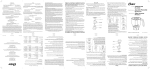
1
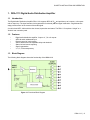
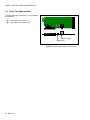
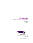
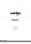
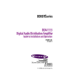
GUIDE TO INSTALLATION AND OPERATION Electromagnetic Compatibility This equipment has been tested for verification of compliance with FCC Part 15, Subpart B requirements for Class A digital devices. NOTE: This equipment has been tested and found to comply with the limits for a Class A digital device, pursuant to part 15 of the FCC Rules. These limits are designed to provide reasonable protection against harmful interference when the equipment is operated in a commercial environment. This equipment generates, uses, and can radiate radio frequency energy and, if not installed and used in accordance with the instruction manual, may cause harmful interference to radio communications. Operation of this equipment in a residential area is likely to cause harmful interference in which case the user will be required to correct the interference at his own expense. This equipment has been tested and found to comply with the requirements of the EMC directive 2004/108/CE: EN 55022 Class A radiated and conducted emissions EN 55024 Immunity of Information Technology Equipment EN 61000-3-2 Harmonic current injection EN 61000-3-3 Limitation of voltage changes, voltage fluctuations and flicker EN 61000-4-2 Electrostatic discharge immunity EN 61000-4-3 Radiated electromagnetic field immunity – radio frequencies EN 61000-4-4 Electrical fast transient immunity EN 61000-4-5 Surge immunity EN 61000-4-11 Voltage dips, short interruptions and voltage variations immunity How to contact us: For technical assistance, please contact the Miranda Technical support centre nearest you: Americas Telephone: +1-800-224-7882 e-mail: [email protected] Asia Telephone: +852-2539-6987 e-mail: [email protected] Europe, Middle East, Africa, UK Telephone: +44 (0) 1491 820222 e-mail: [email protected] China Telephone: +86-10-5873-1814 e-mail: [email protected] France (only) Telephone: +33 (0) 1 55 86 87 88 e-mail: [email protected] Visit our web site at www.miranda.com DDA-1113 GUIDE TO INSTALLATION AND OPERATION Table of Contents 1. DDA-1113 Digital Audio Distribution Amplifier ....................................................................... 5 1.1 1.2 1.3 1.4 2 Installation .................................................................................................................................. 7 2.1 2.2 2.3 3 Unpacking ........................................................................................................................................... 7 Installation in the Densité frame.......................................................................................................... 7 Rear Connector Panel ........................................................................................................................ 7 Operation .................................................................................................................................... 8 3.1 3.2 3.3 4 Introduction ......................................................................................................................................... 5 Features .............................................................................................................................................. 5 Block Diagram ..................................................................................................................................... 5 Front Card-edge Interface................................................................................................................... 6 Card-Edge Controls and Indicators – Status Led ............................................................................... 8 Local control using the Densité frame control panel ........................................................................... 9 3.2.1 Overview ................................................................................................................................ 9 3.2.2 Menu for local control............................................................................................................. 9 iControl Interface ............................................................................................................................... 11 3.3.1 Status Tab ............................................................................................................................ 11 3.3.2 Config Tab............................................................................................................................ 11 3.3.3 Alarms Tab ........................................................................................................................... 12 3.3.4 Info Tab ................................................................................................................................ 14 Specifications ........................................................................................................................... 15 DDA-1113 GUIDE TO INSTALLATION AND OPERATION DDA-1113 GUIDE TO INSTALLATION AND OPERATION 1. DDA-1113 Digital Audio Distribution Amplifier 1.1 Introduction The Digital Audio Distribution Amplifier DDA-1113 supports AES3-id 75 and provides up to 9 outputs, or 8 outputs with an input loop. The input features clock regeneration for reduced jitter and signal restoration. A signal detection stage permits control of the content of the audio signal. A multi-colored LED, visible with the door closed, reports the card status. The DDA-1113 requires a "single" or a "double" rear connector panel. 1.2 Features • • • • • • • 1.3 Digital audio distribution amplifier 1 input to 4, 7, 8 or 9 outputs AES3-id audio unbalanced input Remote control of carrier quality Silence detect with user adjustable delay and threshold Status Led and remote reporting Signal regeneration V, U, C, P bits transparency Block Diagram The following block diagram shows the functionality of the DDA-1113. Figure 1.1 Functional Block Diagram DDA-1113 | 5 GUIDE TO INSTALLATION AND OPERATION SDA-1101 - SD DIGITAL VIDEO DISTRIBUTION AMPLIFIER 1.4 Front Card-edge Interface The front card-edge of the DDA-1113 incorporates two elements: Select Status Status LED (see section 3.1) Select Button (see section 3.2) DDA-1113 SELECT button Status LED Figure 1.2 Card-edge controls and indicators 6 | DDA-1113 GUIDE TO INSTALLATION AND OPERATION 2 Installation 2.1 Unpacking Make sure the following items have been shipped with your DDA-1113. If any of the following items are missing, contact your distributor or Miranda Technologies Inc. For a DENSITÉ-2 frame: DDA-1113 Digital Audio Distribution Amplifier One of the DDA-1113 2RU rear panels Figure 2.1 DDA-1113 2RU Rear Panels For a DENSITÉ-3 frame: Figure 2.2 3RU Rear Panel DDA-1113 Digital Audio Distribution Amplifier including 3RU adaptor One of the DDA-1113 2RU rear panels including 3RU adaptor, or a DDA-1113-3SRP 2.2 Installation in the Densité frame The DDA-1113 and its associated connector rear panel must be mounted in a DENSITÉ-2 or DENSITÉ-3 frame. It is not necessary to switch off the frame’s power when installing or removing the card. See the DENSITÉ Frame manual for detailed instructions for installing cards and their associated rear panels. This card is sized for DENSITÉ-2, but can be installed in DENSITÉ-3 with the use of available adapters for the card and the rear panel. 2.3 Rear Connector Panel When used with a dual-slot rear panel, the DDA-1113 must be installed in the right-most of the two slots covered by the panel in order to mate with the panel’s connectors. If it is placed in the wrong slot, the front panel LED will flash red. Move the card to other slot for correct operation. No damage will result to the card if this occurs. DDA-1113 | 7 GUIDE TO INSTALLATION AND OPERATION The rear panel provides the following connections on BNC connectors: 1 AES-3id input a passive loop-through only for DDA-1113-DRP/L 4 and up to 9 outputs 3 Operation 3.1 Card-Edge Controls and Indicators – Status Led The status monitor LED is located on the front card-edge of the DDA-1113, and is visible through the front access door of the DENSITÉ frame. This multi-color LED indicates the status of the DDA-1113 by color, and by flashing/steady illumination. The chart shows how the various error conditions that can be flagged on the DDA-1113 affect the LED status. If a cell is gray, the error condition cannot cause the LED to assume that status If more than one LED status is possible for a particular error condition, the status is configurable. See Section 3.2.2 for details. The factory default status is shown by a The LED will always show the most severe detected error status that it is configured to display, and in the chart error severity increases from left to right, with green representing no error/disabled, and flashing red the most severe error. LED Status Error Condition No errors Green Yellow Red No input lock Biphase Coding Error Parity Error CRCC Error Slipped sample Confidence Invalid Non audio No signal input 1 No signal input 2 Hardware Failure / No Rear Flashing Red If the LED is Flashing Yellow, it means that the card is selected for local control using the Densité frame’s control panel. See Section 3.2 for details. 8 | DDA-1113 GUIDE TO INSTALLATION AND OPERATION 3.2 Local control using the Densité frame control panel 3.2.1 Overview Push the SELECT button on the DDA-1113 card edge (see Section 1.4) to assign the local control panel to operate the DDA-1113. Use the control panel buttons to navigate through the menu, as described below. All of the cards installed in a Densité frame are connected to the frame’s controller card, which handles all interaction between the cards and the outside world. There are no operating controls located on the cards themselves. The controller supports remote operation via its Ethernet ports, and local operation using its integrated control panel. The local control panel is fastened to the controller card by a hinged connector, and when installed is located in the front center of the frame, positioned in front of the power supplies. The panel consists of a display unit capable of displaying two lines of text, each 16 characters in length, and five pushbuttons. The panel is assigned to operate any card in the frame by pushing the SELECT button on the front edge of that card. Pushing the CONTROLLER button on the control panel selects the Controller card itself. The STATUS LED on the selected card flashes yellow. The local control panel displays a menu that can be navigated using the four pushbuttons located beneath the display. The functionality of the pushbuttons is as follows: [+] [–] Used for menu navigation and value modification CONTROLLER ESC + - SELECT Figure 3.1 Densité Frame local control panel [SELECT] Gives access to the next menu level. When a parameter value is shown, pushing this button once enables modification of the value using the [+] and [–] buttons; a second push confirms the new value [ESC] Cancels the effect of parameter value changes that have not been confirmed; pushing [ESC] causes the parameter to revert to its former value. Pushing [ESC] moves the user back up to the previous menu level. At the main menu, [ESC] does not exit the menu system. To exit, re-push the [SELECT] button for the card being controlled. If no controls are operated for 30 seconds, the controller reverts to its normal standby status, and the selected card’s STATUS LED reverts to its normal operating mode. If a parameter was changed on the card but not submitted (SELECT was not pressed) and the 30 second timeout occurs, the parameters will be confirmed as if the SELECT key had been pressed. 3.2.2 Menu for local control The DDA-1113 has operating parameters which may be adjusted locally at the controller card interface. Press the SELECT button on the DDA-1113 front card edge to assign the Densité frame’s local control panel to the DDA-1113 Use the keys on the local control panel to step through the displayed menu to configure and adjust the DDA1113. Using the menu, the user can: o Display the error status if any is present DDA-1113 | 9 GUIDE TO INSTALLATION AND OPERATION o Adjust the Signal Delay and Signal Threshold to set the conditions of a No Signal alarm. A signal absence is declared when the level is lower than the threshold during the selected period. o Adjust the correction applied to the input signal: AUTO A START will initiate an automatic sequence, indicated by PROCESS. When the input status becomes correct it will stop and SUCCESS will be displayed. FAIL will be displayed to indicate that no correction has been found that will yield to a correct input status. LENGTH This command allows a manual adjustment of the correction applied to the input signal. The input status is displayed at the same time to ease the setting. o Set the input termination to 75 Ohm or to high impedance. o Adjust the Signal threshold, to set the level below which a low signal alarm will be flagged o Adjust the Overload threshold, to set the level above which an overload alarm will be flagged o Configure the different alarms, setting the alarm level (color displayed on the front panel status LED, and severity reported to the frame controller) and selecting whether the alarm is to be reported on the frame’s GPI interface. o Access the firmware version of the card programmable devices. 10 | DDA-1113 GUIDE TO INSTALLATION AND OPERATION 3.3 iControl Interface The operation of the DDA-1113 may be controlled using Miranda’s iControl system. This section describes the control panels associated with the DDA-1113 and their uses. Please consult the iControl User’s Guide for information about setting up and operating iControl. In iControl Navigator or iControl Websites, double-click on the DDA-1113 icon to open the control panel. Status Icons At the top, to the left of the Miranda logo, are two status icons that report various aspects of the card’s operation. The leftmost (CTRL) icon shows whether card configuration is manual [LOC] or via iControl [REM]. The second icon reports the input status. Move the cursor over an icon to see its current status in the message area below the icons. If there is an error status, the message will appear automatically. If there are multiple error messages, the display will cycle through them. Load Factory The Factory profile is a read-only set of factory-selected values that can be used to return your DDA-1113 to a standard operating condition. Figure 3.2 Status Tab The default values are shown as underlined in the DDA-1113 Menu on page 10. 3.3.1 Status Tab This tab displays the status of the various errors that could be associated with the input signal. The PCM Status box will display either PCM, non-audio, Dolby-E or AC-3 according to the type of audio signal. 3.3.2 Config Tab No Signal Delay This tab sets the card’s behavior in the event of a loss or absence of audio signal content. A signal absence is declared when the signal level is lower than the signal threshold during the selected period. The threshold can be set through the pull-down box to –72, -66, -60, -54 or -48 dBFS, the default value is –60 dBFS. The signal absence period can be adjusted from 0 to 255 seconds. The default value is set to 15 s, an input box is available to enter a numerical value directly. Cable Correction Mode MANUAL This mode allows a manual adjustment of the correction applied to the input signal. Look at the input status icon to facilitate the setting. An input box is available to enter a numerical value directly. Figure 3.3 Config Tab DDA-1113 | 11 GUIDE TO INSTALLATION AND OPERATION Mode AUTO A START will initiate an automatic sequence, indicated by PROCESS. When the input status becomes correct it will stop and SUCCESS will be displayed. FAIL will be displayed to indicate that no correction has been found that will yield a correct input status Input Load The Hi-Z selection is to be used along with a rear panel DDA-1113-DRP/L only to insure that the input signal is loaded only once at the end of the chain. 3.3.3 Alarms Tab Figure 3.4 Alarms Tab Selecting the Alarm config button opens a separate window for error status reporting. The alarm Configuration Panel shows a listing of the alarms reported by the card. The Card LED, Overall alarm and GSM contribution columns contain pull-down lists that allow the level of contribution of each individual alarm to the alarm named in the column heading to be set. Card LED This column allows configuration of the contribution of selected individual alarms to the status LED located on the front card edge. The Card LED status is shown at the bottom of the alarm tree in the Status/Name column. Overall Alarm This column allows configuration of the contribution of each individual alarm to the Overall Alarm associated with this card. The Overall Status is reflected by the color of the indicator attached to the card in iControl Navigator. It is also displayed in the upper left corner of the iControl Interface of the DDA-1113. GSM Contribution This column allows configuration of the contribution of each individual alarm to the GSM Alarm Status associated with this card. GSM is a dynamic register of all iControl system alarms, and is also an alarm provider for external applications. The possible values for this contribution are related to the Overall alarm contribution: • If the Overall alarm contribution is set to Disabled, the GSM alarm contribution can be set to any available value • If the Overall alarm contribution is selected as any level other than disabled, the GSM contribution is forced to follow the Overall Alarm. 12 | DDA-1113 GUIDE TO INSTALLATION AND OPERATION Levels associated with these alarms: the pull-down lists may contain some or all of the following options: The alarm makes no contribution (black icon) The alarm is of minor importance (yellow icon) The alarm is of major importance (orange icon) The alarm is of critical importance (red icon) The alarm exists but has no effect (used for text and composite alarms) Shortcut: if you click in one of the Set all command under each major heading in the Status/Name line, you will open a pull-down that lets you assign a level to all alarms in that column simultaneously. Log Events iControl maintains a log of alarm events associated with the card. The log is useful for troubleshooting and identifying event sequences. Click in the checkbox to enable logging of alarm events for each individual alarm. At the bottom of the window are several other controls: Overall alarm and GSM contribution follow card LED Click in the checkbox to force the Overall alarm and GSM contribution to be identical to the Card LED status All Overall alarms and GSM contributions for which there is a Card LED alarm will be forced to match the Card LED alarm All Overall Alarms and GSM contributions for which there is no Card LED alarm will be forced to Disabled A warning box will open allowing you to confirm the action, since it will result in changes to the configuration and there is no undo function. . Figure 3.5 Overall Follow Card Led - Warning Box Copy to other cards Click this button to open a panel that allows the alarm configuration set for this card to be copied into another DDA1113 card. Select one or more destination cards from the list in the window by clicking in check boxes, or all of them by clicking in the All checkbox. Figure 3.6 Copy to Other Cards DDA-1113 | 13 GUIDE TO INSTALLATION AND OPERATION Get alarm keys Click this button to open a save dialog where you can save a file containing a list of all alarms on this card and their current values, along with an Alarm Key for each. The alarm keys are useful for system integration and troubleshooting. The file is saved in .csv format Figure 3.7 Get Alarm Keys 3.3.4 Info Tab The Info panel provides the user information about the DDA-1113. The boxes titled Label, Short Label, Source ID and Comments are editable; the user can enter their own information. The Advanced button displays the name of the server within the iControl system, the frame into which it is installed, the slot occupied by the card and it’s ID (130 for DDA-1113). The Details button displays the card firmware version. The Remote System Administration button at the bottom of the window opens a data entry box titled Joining Locators, in which the ADD option opens a dialog box in which the user can identify the Locator by its URL Figure 3.8 Info Tab 14 | DDA-1113 GUIDE TO INSTALLATION AND OPERATION 4 Specifications Input Signal Level Impedance Return loss Equalization AES3-id (SMPTE 276M) 0.1 to 7.0 Vpp 75 unbalanced or Hi-Z (selection by a command) 25 dB @6.144MHz With –SRP, -DRP or 2 x –DRP/L 0 to >2000 m Outputs Signal Level Impedance Rise/fall time Overshoot Return loss Jitter reduction Specific jitter AES3-id (SMPTE 276M) 1 Vpp 75 unbalanced 36/32 ns 0% 15 dB @6.144MHz 6 dB (@ 20 kHz) <0.005 UI pp (700 Hz to 100 kHz) Signal Processing Sampling: 28 to 100 kHz Processing delay Signal absence threshold Signal absence delay V, U, C, P bits transparency <60.7 µs @ 48kHz (< 3 samples) -48 / -72 dBFS (6 dB step) from 0 to 255 s Miscellaneous Power 4 outputs: 0.8 W Up to 9 outputs: 1.3 W DDA-1113 | 15