1
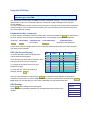
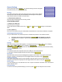
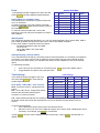
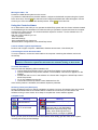
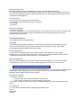
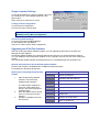
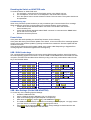
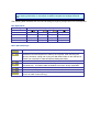
Installation guide
Specifications
Part No’s
1018-108
1018-116
Switches
SCOUTutp 8 port Switch
SCOUTutp 16 port Switch
2364-01P
2364-01U
2364-01S
CPU Adaptors
SCOUTutp PS/2 CPU adapter
SCOUTutp USB CPU adapter
SCOUTutp SUN CPU adapter
SCOUTutp
Height
Width
Depth
Weight
SCOUTutp 8 port
4.15cm / 1.63” 21.5cm / 8.46” 12.20cm / 4.80” 0.92 kg / 2.0 lb
SCOUTutp 16 port
4.15cm / 1.63” 21.5cm / 8.46” 12.20cm / 4.80” 0.92 kg / 2.0 lb
Operating Temperature:
0~40° C ( 32 ~ 104° F)
Storage Temperature:
-40~70° C (-40 ~ 158° F)
Humidity:
80% RH non-condensing
Operating Systems
DOS, Windows (9X, NT4, 2000, XP, 2003 Server) LINUX, UNIX, QNX,
SGI, FreeBSD, BeOS, Open VMS, Novell, Alpha UNIX, HP UX, SUN
Mouse
PS/2, Wheel mouse, Intellimouse, 5-button mouse
Resolution
1600x1200@85Hz
Transmission distance
Up to 10m (33ft)
Power supply
Internal switching 85-260 VAC 50 / 60 Hz
Connections
System
RJ45
Serial
RJ11
Local KVM
HDD15 / PS/2 - MinDin6 / PS/2 - MiniDin6
CPU Adaptors
PS/2
USB
SUN
Video
HD15
HD15
HD15
Keyboard/Mouse
MiniDin6
USB
MiniDin8
System
RJ45
RJ45
RJ45
Power
From computer’s
Keyboard port
From USB port
From computer’s
Keyboard port
Connections
Product weight
107g / 0.23lb
Shipping weight
300g / 0.66lb
Dimensions
91 x 41 x 24mm / 3.58 x 1.61 x 0.94”
NOTE: This equipment complies with the requirements of European EMC directive 89/336 EEC in
respect of EN55022 Class B, EN 50082-1 and EN 60555-2.
This equipment has been found to comply with the limits for a Class A digital device, pursuant to
Part 15 of the FCC Rules. These limits are designed to provide reasonable protection against
harmful interference when the equipment is operated in a commercial environment. This
equipment generates, uses, and can radiate radio frequency energy and, if not installed and used
in accordance with the instruction manual, may cause harmful interference to radio
communications. Operation of this equipment in a residential area is likely to cause harmful
interference in which case the user will be required to correct the interference at his own expense.
© Copyright 2004. All rights reserved.
Daxten, the Daxten logo, SCOUTutp and The Brains Behind KVM Switching and Sharing are trademarks of Daxten Industries.
All other trademarks acknowledged.
Revision 1.1
SCOUTutp
Introduction
Thank you for purchasing the SCOUTutp KVM Switch. This product will ensure easy and accurate
control over 8 – 16 PCs from a single console. The SCOUTutp is compatible with PS/2, USB and SUN
style computers with its specific adapters. It has keyboard and mouse emulation for error free bootups and supports a wide variety of mice including the Microsoft Intellimouse. The SCOUTutp supports
high resolutions of up to 1600 x 1200 without any deterioration of the image quality. Switching
between PCs can be accomplished through keyboard Hot Key commands, the front panel or through
the OSD (On-Screen-Display).
Product Features
¾
¾
¾
¾
¾
¾
¾
¾
¾
¾
¾
Allows a user to control 8 - 16 computers from one console.
Supports PS/2, USB and SUN computers through an adapter for each platform
1U Rack mountable
Distance between console and computer can be up to 10m with simple CAT5 cabling
No drivers or additional software are required for operation.
Keyboard and mouse emulation allows for error free boot-up.
Supports video resolutions of up to 1600 x 1200 @ 85Hz.
Supports VGA, SVGA and XGA monitors.
Keyboard Hot Key, OSD control or the front panel.
Comes with Auto-Scan mode for convenient automatic switching.
Front panel status LEDs give a clear indication of the active PC.
Installation
Before connecting your computers and console devices to the SCOUTutp switch, please ensure that
all devices are powered off.
1.
Connecting the console devices with SCOUTutp:
Connect your monitor’s HD 15-pin connector to the SCOUTutp’s Monitor connector on
the rear panel.
Connect your PS/2 keyboard to the PS/2 keyboard connector (purple) and your PS/2
mouse to the PS/2 mouse connector (green) on the rear panel of the SCOUTutp.
2.
Connecting the computers with an UTP patch cable and a PS/2 adapter :
Connect the blue HD 15-pin male connector to the VGA port on your computer.
Connect the purple PS/2 (6-pin Mini DIN) keyboard connector to the PS/2 keyboard
port on your computer.
Connect the green PS/2 (6-pin Mini DIN) mouse connector to the PS/2 mouse port on
your computer.
Connect the UTP cable with the PS/2 adapter and the desired SCOUTutp computer
port.
3.
Connecting the computers with an UTP patch cable and a USB adapter:
Connect the blue HD 15-pin male connector to the VGA port on your computer.
Connect the USB connector to a USB port on your computer.
Connect the UTP cable with the USB adapter and the desired SCOUTutp computer
port.
4.
Connecting the computers with an UTP patch cable and a SUN adapter:
Connect the blue HD 15-pin male connector to the VGA port on your computer.
Connect the SUN connector to the keyboard & mouse port on your computer.
Connect the UTP cable with the SUN adapter and the desired SCOUTutp computer
port.
5.
Power up the SCOUTutp
Using the SCOUTutp
Note: Before switching your computers on, please configure non PS/2 computers
emulation type in the OSD!
The SCOUTutp provides three possibilities to select the desired computer. You may use either the
Select button on the unit, the keyboard Hot Key commands or take advantage of the OSD (OnScreen-Display).
You may notice that the mouse cannot be used for around 1 second when the SCOUTutp switches to
another computer. This is normal and is caused by the synchronization process which ensures that
the mouse operates correctly.
Keyboard Hot Key commands
To send Hot Key commands to the SCOUTutp switch, press and release the Ctrl key twice within 2
seconds. Press a command key for the desired effect. The following commands are supported:
First Key
Ctrl
Second Key
Ctrl
Command Key
Port number
Confirmation Key
Enter
Command Result
Switches to the desired PC
In Auto-Scan mode, the image shown on the monitor will automatically switch to the next computer.
The delay is user definable
OSD (On-Screen-Display)
To access the OSD, press the Hot Key twice
and the OSD window appears:
Lines with blue text show active computers, lines
with grey text show inactive computers.
To navigate up and down use the UP and
DOWN arrow keys.
To jump from one column to another (in
Settings) use the Tab key.
Port
No.
01
02
03
04
05
06
07
08
Computer
Name
SUN
PS/2 1
SCOUT
SUN
PS/2 3
USB
USB
PS/2 4
No.
01
02
03
04
05
06
07
08
C = computer
S = switch
C
C
S
C
C
C
C
C
blue
grey
grey
blue
blue
grey
grey
blue
After you have selected a computer press Enter . A confirmation label appears showing which
computer you accessed. To exit the OSD or return to a previous window within the OSD press ESC .
Note: When you use the OSD you can’t use the keyboard Hot Keys at the same time.
OSD Settings
Press F2 and the setting window will appear.
When the OSD is password protected only the administrator has access to this
window.
OSD Settings
General
Ports
Time
Users
Security
General Settings
Select General and press ENTER , the General Settings window will appear.
From this window you can do the following:
Security
The OSD comes with an advanced password security system with 3 different
security levels. Each security level has different access rights to the system
and have are limited in number as shown below.
General Settings
Security
Hotkey
Autoskip
Serial port
Keyboard language
Switch name
1 x Administrator (Status A)
Set and modify all Passwords and security profiles
Fully access any computer
Access all OSD functions
1 x Supervisor (Status S)
Fully access any computer
Access the following OSD functions only – F4 Scan, F5 Tune and F6 Moving the Confirmation
label.
6 x User (Status U)
Each User has a profile set by the Administrator that defines the access level to different computers.
Activating password protection
Only the Administrator can password-protect or disable the protection of the OSD as follows:
1.
2.
3.
Navigate to the Security line and press the Space Bar to toggle between On and Off.
The password box appears. Type the Administrators password (default password is
admin).
Press Enter
Hot Key
Press the Hot Key and the OSD appears. To change the Hot Key to [ Ctrl Ctrl ] (CL on display),
[Ctrl , F11 ], [Shift , Shift ] (SH on display) or Print Screen.
Press the Space Bar to toggle between the different options. Once selected, press the new Hot Key
to display the OSD in the future.
Autoskip
To access only the active computer lines on the OSD you can use this feature.
To activate the Autoskip toggle between the options with the Space Bar.
Serial port
Serial port ON means the Control Management program can be used. To change the Serial port
settings, navigate to the Serial port line and toggle between the options using Space Bar.
Keyboard language
The default is US English which can be changed to German (DE) or French (FR) as follows:
Navigate to the Keyboard language line and toggle between the options using the Space Bar.
Switch name
You can substitute up to 18 characters in the line. A space constitutes a character. Give each switch’s
OSD a different name.
Factory Default
To return to the factory default Settings you have to press F7 and all changes will be removed.
Ports
PORTS SETTINGS
In the Settings window navigate to the Ports line and
press ENTER. The Ports Settings window appears.
Name (Editing the computer name)
In this window you can edit the computer names with
up to 15 characters.
To erase a character you have to select it and then
press the Space Bar. Blank spaces remain in place of
the character.
To erase an entire line place the cursor at the
beginning of the line and press the space bar until the
line is erased.
Name
01
02
03
04
05
06
07
08
COMPUTER
COMPUTER
SWITCH
COMPUTER
COMPUTER
COMPUTER
COMPUTER
COMPUTER
01
02
03
04
05
06
07
08
KB
HKEY
PS
U1
PS
PS
U2
U3
PS
PS
NO
NO
CLF11
NO
NO
NO
NO
NO
(KB) Keyboard
The SCOUTutp operates with Windows, Linux, HP UX, Alpha UNIX SGI, DOS, Novell, MAC, USB or
Open VMS. By default the keyboard mode is set to PS for Intel based computers.
For the other systems set the KB column as follows:
PS Standard keyboard, MAC and SUN
U1 for HP UX
U2 for Alpha UNIX, SGI, Open VMS
U3 IBM AIX
Adding/changing a Hot Key (HKEY)
If you cascade the SCOUTutp by connecting another SCOUTutp Switch to a computer port instead of
a computer, you have to connect the utp cables to the new switch and you have to define the HOT
KEYS for the new OSD. When you cascade these hotkeys must be different for the top and bottom
layers.
To add/change a hotkey:
1.
2.
On the line to which the Switch is connected, press Tab to jump to the HKEY column.
Toggle between the options using the space bar.
Time Settings
Time Settings
NAME
SCN
LBL
01
COMPUTER
030
030
02
COMPUTER
030
030
03
SWITCH
030
030
Scan (SCN) - Label (LBL) - Time out (T/O)
0
4
COMPUTER
0
3
0
0
30
SCN - In the SCN column, changes the scan
05
COMPUTER
030
030
period.
LBL - In the LBL column, changes the display
06
COMPUTER
030
030
period of the OSD label showing which
07
COMPUTER
030
030
computer is currently accessed.
08
COMPUTER
030
030
T/O - When password protection is activated you can automatically disable the Management
keyboard, mouse and screen after a preset time of non-use. Set this Timeout period in the T/O
column.
In the Settings window navigate to the Time
line and press ENTER. The Time Settings
window appears
T/0
030
030
030
030
030
030
030
030
To set the above periods:
1.
On the desired line press Tab to jump to the desired column.
2.
Place the cursor over one of the 3 digits and type a new number. Enter a leading zero where
necessary. For example, type 0 4 0 for 40 seconds.
Typing 9 9 9 in the LBL column displays the label continuously. Typing 0 0 0 – the label will not
appear.
Typing 9 9 9 in the T/O column disables the Timeout function. Typing 0 0 0 – the Timeout function
works immediately. We recommend a T/O setting of at least 10 seconds.
Typing 9 9 9 in the SCN column displays the screen for 999 seconds. Typing 0 0 0 – the computer
screen is skipped.
Users
In the Settings window navigate to the Users
line and press Enter . The Users Settings
window appears.
Turn on the Security feature (under OSD
Settings) to configure any Users Settings.
There are 3 different access levels. These are:
Y – Full access to a particular computer. Plus
access to the F4 , F5 and F6 OSD functions
V –Viewing access only, to a particular
computer (No keyboard/mouse functionality)
N – No access to a particular computer – A
TIMEOUT label appears if access is attempted
01
02
03
04
05
06
07
08
USERS SETTINGS
USERS
1 2 3
COMPUTER 0 1 Y Y Y
COMPUTER 0 2 V V Y
SWITCH
03 Y Y Y
COMPUTER 0 4 V V V
COMPUTER 0 5 N N Y
COMPUTER 0 6 V V N
COMPUTER 0 7 Y Y Y
COMPUTER 0 8 Y Y Y
4
V
Y
Y
V
N
N
Y
Y
5
N
N
Y
V
N
N
Y
Y
6
V
V
Y
V
V
V
Y
Y
To give a user the desired access level, navigate to the desired computer line and USER and toggle
between the options using the space bar.
Security
In the Settings window navigate to the Security line and
press Enter . The Security Settings window appears.
In the window above you can see the Name of the User, his
password and the type of the password.
To change a user name or password you have to navigate
to the desired line and column. Type a new user name or
password. User authentication is done solely via the
password. There is no security significance to the names.
SECURITY SETTINGS
NAME
PASSWORD
ADMINISTRATOR ADMIN
SUPERVISOR
S
USER
1
USER
2
USER
3
USER
4
USER
5
USER
6
T
A
S
U
U
U
U
U
U
The OSD HELP window – F1
To access the HELP window press F1 . The HELP window appears:
Please note! All the functions set out in the Help window are performed from the Main window. The
Help window is merely a reminder of the hotkeys and their functions.
Scanning computers– F4
Where necessary adjust the scan time in the Time Settings window, see above.
To activate scanning:
Press the Hot Key twice to open the OSD.
Press F4 . Your screen displays each active computer sequentially, with the Scan label appearing in
the top left corner.
Press F4 to deactivate scanning:
Tuning – F5
You can tune the image of any remote computer screen from the Select Computer window.
To adjust the screen image:
Navigate to the remote computer you wish to adjust.
Press F5 . The screen image of the selected computer appears, together with the Image Tuning label.
Adjust the image by using the Right and Left Arrow keys, when the image is satisfactory, press Esc .
Note! Picture quality is relative to distance. The further away a remote computer is from
the SCOUTutp, the lower the image quality, and the more tuning needed. Place the
higher resolution computers closer to the main unit.
Moving the label – F6
Position the OSD label anywhere on the screen.
To position the OSD label from the Main window, navigate to the desired computer using the Up and
Down arrow keys. Press F6 . The selected screen image and Identification label will appear. Use the
arrow keys to move the label to the desired position. Press Esc to save and exit.
Using the Control software
As an alternative to the OSD you can operate the SCOUTutp system with the Control software located
on the Marketing & Documentation CD. With the OSD you operate the system and view the computer
screens on the same monitor. The Control software requires 2 monitors 1 for the software and 1 to
view the computer screens.
With the Control software you can:
-View computers
-Edit OSD Settings
-Save configurations for future use
-Read and write configurations to the SCOUTutp Switch
Control software system requirements
Pentium 166 or higher computer, 16Mb RAM, Windows 98 and later, a free Serial port
Connecting the serial download cable
To run the software, connect the serial cable to the computer containing the software, and to the
SCOUTutp.
Note! The system must be fully connected BEFORE running the Control software.
Failure to connect the system first will lead to the software working in demo mode.
To install the software:
Insert and start the Marketing & Documentation CD.
¾ Choose SCOUTutp RS232 Control. The SCOUTutp RS232 Control window appears.
¾ Choose Install SCOUTutp Control Software. Once installed, a shortcut icon appears on the
Desktop.
¾ Double-click the icon to run the software. Or choose Start / Programs / SCOUTutp Control /
SCOUTutp Control.
¾ To run the software from the CD:
¾ Choose Run SCOUTutp switch Control Software from CD.
If the Security feature is activated, the software requires a password.
Selecting a Com port (Serial port)
During the Setup process you will be prompted to choose a Com port. Choose the Com port to which
the serial download cable is connected. Failure to select the correct Com port will result in the
software running in demo mode. Once Setup is complete the Control window appears.
Computer icons
Icon
Meaning
Computer is connected
and switched on
Computer is switched
off or unconnected
Icon
Meaning
Computer that you are presently
connected to
Connected and switched on
computer with a Local Workstation
attached and presently being used
locally. After remaining idle for the
Timeout period, it changes to yellow.
When you first open the Control window the software automatically gets the status of the system,
including the security access Settings.
Communication Error
If a Communication Error box appears when trying to scan the system, check that:
The Serial download cable is connected to the computer’s and SCOUTutp IP Manager’s serial ports.
The Com Port Settings in Options / Com Port are set correctly. After changing the Com port exit and
re-start the Control software.
The View menu
From the View menu choose one of the following:
-All computers, or only active switched on computers.
-The Legend
-The toolbar
Selecting a computer
To select a computer:
Click on the computers icon. The system switches to that computer. The connected icon appears with
a red background. Control and monitor the selected computer from the keyboard and mouse
connected to the SCOUTutp.
The toolbar buttons
The toolbar buttons are explained below.
Get Status
If for whatever reason there is a break in communication between the Control software and the
system, click “Get Status” to get the current status of the computers in system. The system
automatically updates the status before every switch.
Read Configuration
To see the current Settings of the entire system (names, scan Settings etc.) click “Read
Configuration”. All current Settings are received. You view the computer Settings from the Control
window and other Settings from the Edit menu – discussed below.
Write Configuration
With the Control software you can make changes to all OSD Settings. You can then save these
configurations in a file to use in the future by selecting Save or Save As from the File menu.
Note! Save or Save As, will have no affect on the OSD.
To change the OSD Settings you must press “Write Configuration” or choose Write Configuration from
the File menu after making changes. The changes will then be sent to the SCOUTutp system
Manager, and the OSD will reflect these changes.
Renaming a computer
To rename a computer:
¾ Type the new name in the box below the computer icon.
¾ Click “Write Configuration” to save the settings on the OSD.
Or click Save or Save As, from the File menu to save the changes in a file and not alter the OSD
names.
The Edit menu
You can edit all OSD fields. Edit the following from the Edit menu.
Logon
Passwords
Settings
Password protection
When the SCOUTutp system is password protected, the Control software behaves in exactly the same
way as the OSD. You must type in the required password to access the Control software. The access
you gain depends on the security status –.
To change the security access, close and reopen the Control software, and type in the different
passwords.
Administrator (Status A)
The Administrator can:
¾ Set and modify all Passwords and security profiles
¾ Fully access any computer
¾ Use all functions
Supervisor (Status S)
The Supervisor can:
¾ Fully access any computer
¾ Scan computers
User (Status U)
There are 6 different Users in the SCOUTutp system. Each User has a Profile that defines the access
level to different computers. There are 3 different access levels. These are:
¾ Y – Full access to a particular computer
¾ V –Viewing access only, to a particular computer (No keyboard/mouse functionality)
¾ N – No access to a particular computer
By default the User Profile Settings are full access.
Logon and Passwords
You can make the following changes:
1.
Edit the Logon and Passwords by choosing them from the
Edit menu. See figures below.
2.
Make the desired changes.
3.
Click OK.
Settings
Choose Settings from the Edit menu. The
Computers’ Properties box appears.
Here you can edit all the data that can be
edited in the OSD.
To edit a setting:
1.
In the Computer List, select the
desired computer or group of
computers.
2.
Make the desired changes.
3.
Check the Select box next to the changed setting.
4.
Click OK.
5.
To activate the changes press write configuration and then read configuration.
Single computer Settings
To see all the Settings of a single computer, right click
the computer icon. The Settings appear as in the
figure below.
Note! There is no Select box to check.
Loading a saved configuration
To load a saved configuration:
From the File menu choose Open.
Note: All changes done with the Control software are only reflected in the OSD
AFTER pressing “Write Configuration”
The factory default Settings
To revert to the factory default Settings:
On the toolbar press “Set Default”
There is no need to press “Write Configuration”.
Upgrading the SCOUTutp firmware
With the SCOUTutp Update software program you can upgrade the firmware for the OSD, the
Manager and the Adaptors
SCOUTutp Update enables you to add new features and fix bugs in a quick and efficient manner.
You can install the SCOUTutp Switch Update on any computer, even one not part of the SCOUTutp
system.
The SCOUTutp Update software and latest firmware is on the Marketing & Documentation CD.
System requirements for the SCOUTutp Update software
Pentium 166 or higher, 16 MB RAM and 10 MB free Hard Drive space.
Free Serial port. Windows 98 and later.
Starting and configuring the SCOUTutp
Update
1.
2.
3.
Start the SCOUTutp Update
software. The SCOUTutp
Update window appears
The table shown explains the
functions of the buttons and
boxes in the SCOUTutp Switch
Update window.
From the Options menu choose
Com Port. The Com Port box
appears.
Choose an available Com Port
and click OK.
Button or Box
Function
Select
Selects all Adaptors
Unselect
Unselects selected Adaptors
Start
Starts firmware download
F/W
Displays the firmware version number
H/W
Displays the hardware version number
Cancel
Cancels selected function
10:06
System time
Status
Displays download status
File
Name of Update file
Note! The Serial download cable must be connected to the selected Serial port.
Verifying the version numbers
Before upgrading the firmware, you must first verify which firmware and hardware versions you have.
The OSD version number
To verify the OSD version number:
1.
Open the SCOUTutp Switch Update program.
2.
In the Switch Unit box, check the OSD option.
3.
Click F/W Version the version number appears in the Switch box.
The H/W Version button is greyed out, as there is no hardware relevant to the OSD.
The SCOUTutp Manager version number
To verify the SCOUTutp version number:
1.
Open the SCOUTutp Switch Update program.
2.
In the Switch Unit box, check the SCOUTutp Manager option.
3.
Click F/W Version the firmware version number appears in the Switch Unit box.
4.
Click H/W Version the hardware version number appears in the Switch Unit box.
Verifying the ADAPTOR version number
Before you can check a ADAPTOR, you must uncheck the Switch Unit box options.
To verify the ADAPTOR version number:
1.
Open the SCOUTutp Switch Update program.
2.
Check one or more or all of the Adaptors.
3.
Click F/W Version the firmware version number appears after the ADAPTOR number.
4.
Click H/W Version the hardware version number appears after the ADAPTOR number.
When “Not responding” appears, there is no computer connected, or it is switched off.
Updating the firmware
Warning! Never switch off any computer connected to the SCOUTutp system
during the updating process.
To update the firmware:
1.
Open the SCOUTutp Switch Update program.
2.
In the SCOUTutp Switch Update window, check the appropriate option in the Switch Unit box
or the desired ADAPTOR.
3.
From the File menu, choose Open. The Open box appears
4.
Navigate to the folder that contains the firmware update file. You may only see the files that
match the file selection mask.
5.
Open the file.
6.
Click Start. The SCOUTutp Switch Update flashes the firmware. On completion the firmware
version number appears.
7.
Check that the updated version number is correct by pressing F/W Version .
Firmware Update generates one log file per session that displays a chronological list of actions. You
can read the log file in any ASCII text editor. The log file is located in the Windows directory.
Reset
Reset the software for the SCOUTutp Manager or Adaptors when for example the unit hangs or when
the mouse fails to work properly. Resetting is done via the Serial port, and avoids the need to shut
down the computer.
Note! The Reset function does not affect the parameter settings of the unit.
Resetting the Switch or ADAPTOR units
To reset the Switch or ADAPTOR units:
1.
For the Switch, check the SCOUTutp Switch option in the Switch Unit box.
2.
For the Adaptors, check one or more Adaptors in the ADAPTOR Units box.
3.
From the Options menu choose Advanced / Reset. The units reset. The system should now
be operational.
Troubleshooting tips
When using Firmware Update software you may sometimes get a Communication Error message.
When updating a unit and a Communication Error message appears, do the following:
1.
Check that the Serial download cable’s connector is connected to the Switch’s
Communication port.
2.
Check that the Serial download cable’s DB9F connector is connected to the DB9M Serial
port on the CPU’s rear panel.
3.
Restart the download process.
Power failure
If the power fails while updating the SCOUTutp firmware, do the following:
If the power fails during the firmware update of the Switch, a Communication Error message appears.
Simply resume the firmware update by opening the folder that contains the firmware update file and
continue from there.
If the electricity fails during the firmware update of the cables a Not Responding or Upgrade Error
message appears. Restart the upgrade from the beginning.
USB / SUN Combo keys
The connected PS/2 keyboard does not have a special SUN keypad to perform special functions in
the SUN Operating System environment. So when a USB or SUN ADAPTOR is connected to a SUN
computer, the ADAPTOR emulates these SUN keys using a set of key combinations called Combo
keys. See the table below.
SUN key
Stop
Combo key
Left Ctrl + Alt + F1
SUN key
Help
Combo key
Left Ctrl + Alt + F11
Props
Left Ctrl + Alt + F3
Compose
Left Ctrl + Alt + Keypad *
Front
Left Ctrl + Alt + F5
Crescent
Scroll Lock
Open
Left Ctrl + Alt + F7
Volume Up
Left Ctrl + Alt + Keypad –
Find
Left Ctrl + Alt + F9
Volume Down
Left Ctrl + Alt + Keypad +
Again
Left Ctrl + Alt + F2
Mute
Left Ctrl + Alt + F12
Undo
Left Ctrl + Alt + F4
Sun Left ◊ key
Left á key
Copy
Left Ctrl + Alt + F6
Sun Right ◊ key
Right á key
Paste
Left Ctrl + Alt + F8
Alt-Graph
Right Alt or Alt Gr
Cut
Left Ctrl + Alt + F10
Stop A
Left Ctrl + Alt +1
USB / Mac Settings (On the USB ADAPTOR)
To access any of the following Special Settings:
1.
Install the USB ADAPTOR.
2.
Attach a PS/2 keyboard to Manager Unit or to Switch Unit
3.
Open a text-editing program (like Notepad or SimpleText)
4.
Hold down the Esc key, tap the S key, and release the Esc key.
5.
The USB-to-PS/2 conversion chip version and settings will be displayed: “v2.1[wp]” means
you have version 2.1 and the “W” and “P” settings are active.
6.
Using Esc and the appropriate letter, you may change settings as desired and the new
configuration will be displayed in the text editor.
NOTE: The USB ADAPTOR stores these settings in their own internal memory so even
if you unplug, power down, or move them to another computer, the settings will not be
lost.
The following table illustrates how the W and R settings change key assignments on a PS/2 keyboard.
Mac Equivalents
Settings
PS/2 Keyboard Layout
None (Mac default)
W (PC default)
WR
R
Left á key
Left Alt
Right Alt
Right á key
Alt/Option
Command
Alt/Option
Command
Command
Alt/Option
Command
Alt/Option
Command
Alt/Option
Alt/Option
Command
Alt/Option
Command
Command
Alt/Option
More Special Settings
Esc
A
Resets USB ADAPTOR to Mac default (QP).
Esc
E
Esc
O
Stops the normal USB power-off feature. Set this if you want to use the
attached mouse and keyboard to wake up the computer. After executing the
[Esc E] command, unplug and re-plug the USB ADAPTOR from the USB port or
restart your computer to make this Special Setting take effect.
Resets USB ADAPTOR to PC default (WP).
Esc
P
Esc
Q
Scandinavian “*” key code conversion changes the scan code for the <|> (pipe
character) key. This affects UNIX workstations and some foreign keyboards.
Sets the mouse speed to a faster mode.
Esc
T
Allows the operating system to control the “Num Lock” indicator.
Esc
Y
Sets the <Scroll Lock> key as a USB scroll lock. (Default mode uses <Scroll
Lock> as a Mac “Power off” key).
Service Information
Technical Support
If you cannot determine the nature of a problem, please call Daxten and ask for Technical Support. If
possible, call from a phone located near the unit, as we may be able to solve your problem directly
over the phone. If we cannot solve your problem, and determine that the fault is in the unit, we will
issue a Return Material Authorisation (RMA) number that must appear on the outside of all returned
products. The unit should be double-packed in the original container, insured, and shipped to the
address given to you by our Technical Support representative. The Technical Support offices are
found on the back of this manual.
Limited Warranty
Daxten warrants to the end user that this product is and will be free from defects in materials and
workmanship for a period of 24 months from the date of purchase. If during the warranty period the
product should fail, the purchaser must promptly call Daxten for a RETURN MATERIALS
AUTHORIZATION (RMA) number. Make sure that the RMA number appears on the packing slip, proof
of purchase, AND ON THE OUTSIDE OF EACH SHIPPING CARTON. Unauthorized returns or collect
shipments will be refused.
Ship prepaid to the Daxten office (see back page) where you purchased your product. The above
limited warranty is voided by occurrence of any of the following events, upon which the product is
provided as is, with all faults, and with all disclaimers of warranty identified below:
1.
2.
3.
4.
5.
6.
7.
If non-Daxten approved power supply or cabling is attached to the product.
If defect or malfunction was caused by abuse, mishandling, unauthorized repair, or use other
than intended.
If unauthorized modifications were made to product.
If unreported damages occurred in any shipment of the product.
If damages were due to or caused by equipment or software not provided by Daxten.
If the product is used with non-grounded or incorrectly polarized AC power.
If the product is used in contradiction to any instruction provided by any User Guide or
Instruction Sheet provided to you or with the product.
EXCEPT AS SPECIFICALLY PROVIDED ABOVE AND TO THE MAXIMUM EXTENT ALLOWED BY
LAW, DAXTEN DISCLAIMS ALL WARRANTIES AND CONDITIONS WHETHER EXPRESS,
IMPLIED, OR STATUTORY AS TO ANY MATTER WHATSOEVER INCLUDING, WITHOUT
LIMITATION, TITLE, NON-INFRINGEMENT, CONDITION, MERCHANTABILITY OR FITNESS FOR
ANY PARTICULAR OR INTENDED PURPOSE.
EXCEPT AS EXPRESSLY PROVIDED ABOVE AND TO THE MAXIMUM EXTENT ALLOWED BY
LAW, DAXTEN SHALL NOT BE LIABLE FOR ANY SPECIAL, INDIRECT OR CONSEQUENTIAL
DAMAGES (INCLUDING WITHOUT LIMITATION, LOSS OF PROFIT, LOSS OF BUSINESS, LOSS
OF INFORMATION, FINANCIAL LOSS, PERSONAL INJURY, LOSS OF PRIVACY OR
NEGLIGENCE) WHICH MAY BE CAUSED BY OR RELATED TO, DIRECTLY OR INDIRECTLY, THE
USE OF A PRODUCT OR SERVICE, THE INABILITY TO USE A PRODUCT OR SERVICE,
INADEQUACY OF A PRODUCT OR SERVICE FOR ANY PURPOSE OR USE THEREOF OR BY
ANY DEFECT OR DEFICIENCY THEREIN EVEN IF DAXTEN OR AN AUTHORIZED DAXTEN
DEALER HAS BEEN ADVISED OF THE POSSIBILITY OF SUCH DAMAGES OR LOSSES.
Waste Electrical and Electronic Equipment (WEEE)
Within the European this symbol indicates that this product should not be disposed in
household waste. It should be deposited at an appropriate facility to enable recovery and
recycling. For information on how to recycle this product, please check with the reseller of the
product that replaces this product "Take Back" or the original seller of this product.
www.daxten.com
Ireland
Bay 21
Free Zone West
Shannon, Co. Clare
[email protected]
www.daxten.ie
Tel: +353 (0) 61 23 4000
Fax: +353 (0) 61 23 4099
USA
811 W. Evergreen Ave
Suite 302A
Chicago, IL 60622
[email protected]
www.daxten.us
Tel: +1 312 475 0795
Fax: +1 312 475 0797
United Kingdom
5 Manhattan Business Park
Westgate
London W5 1UP
[email protected]
www.daxten.co.uk
Tel: +44 (0) 20 8991 6200
Fax: +44 (0) 20 8991 6299
•
•
•
Österreich
Künstlergasse 11/4
A-1150 Wien
[email protected]
www.daxten.at
Tel: +43 (0)1 879 77 65
Fax: +43 (0)1 879 77 65 30
Deutschland
Salzufer 16, Geb. B
10587 Berlin
[email protected]
www.daxten.de
Tel: +49 (0) 30 8595 37-0
Fax: +49 (0) 30 8595 37-99
Schweiz
Seebahnstr. 231
8004 Zürich
[email protected]
www.daxten.ch
Tel: +41 (0) 43 243 32 11
Fax: +41 (0) 43 243 32 16
•
•
•
España
C/Florian Rey, 8
50002 Zaragoza
Sweden
[email protected]
www.daxten.se
[email protected]
www.daxten.com.es
Tel: +34 902 197 662
Fax: +34 976 201 633
Denmark
[email protected]
www.daxten.dk
France
B.P 04 - 77
Route de Cheptainville
91630 Marolles-en-Hurepoix
[email protected]
www.daxten.fr
Tel: +33 (0)1 64 56 09 33
Fax: +33 (0)1 69 14 88 34
•
•
•
•