1
OPERATION MANUAL MBP-12GUILE MBP-12GUI MBP-12 Series Control GUI Version 1.5.4 - Higher ©2012 FOR-A Company Limited. All rights reserved. Contents of this manual may not be copied or reproduced without permission. Software License Agreement This Software License Agreement is a legally binding agreement between you (“User”) and FOR-A Company Limited (“Company”). The software, user manual and all other associated documentation (collectively, “Product”) are licensed, not sold, to the User. By installing and using the software, or by using a product of the Company in which the software is installed, User agrees to be bound by all terms and conditions of this agreement, as set forth below. 1. License Grant a. The Company grants User the license to use the Product in the manner specified in the user manual and other associated documentation. User may not use the Product in any manner other than specified. b. The Company only grants User the license to personally use the Product, and does not allow User to transfer the license to a third person or to enable a third person to use the Product by any other method. c. In principle, the software may only be used on a single computer or device. d. While the software may include various programs, they may not be unbundled and used as standalone programs. 2. Restrictions on Distribution, Duplication, Lease and Transfer User may not, without the Company’s prior permission, distribute via communication lines, or lease or transfer electronic copies of the Product, in whole or in part, nor attempt to do so. 3. Limitations of Guaranty The Company and its program licensors disclaim all legal warranties, express or implied, with respect to the Product. User must use the Product at own risk. In no event shall the Company and its program licensors be liable for any damage resulting from User’s use or inability to use the Product. 4. Provision of Upgrades and Updates Whenever the software is upgraded or updated, User may use the new version of the software by paying the amount separately specified by the Company. After upgrading the software, User may not use the earlier version without the Company’s prior permission. 5. Term of Validity of this Agreement This agreement shall be effective for a period of one year from the day User begins using the software. The same conditions of the agreement shall be extended for further one-year terms unless User or the Company expresses, at least one month prior to expiration of the agreement, the intent not to renew the agreement. 6. Termination of the Agreement a. The Company reserves the right to immediately terminate this agreement if User corresponds to either of the following circumstances. (1) User violates any terms of this agreement (2) User is unable or refuses to make the required payment b. User may terminate this agreement by written notice to the Company in the following circumstances, but may not seek a refund of the amount that User has already paid to the Company. (1) User waives the license (2) User destroys or loses the software package and prevents the Company from being able to confirm its existence c. After termination of this agreement, User may not use the Product in any way or form. 7. Ownership The Company and its program licensors retain all rights, including copyright and intellectual property rights, to the Product. User may not modify any program included in this software, nor disassemble, decompile, or reverse-engineer a program to analyze its source code. 8. Others This agreement will be governed by and construed in accordance with copyright laws and treaties in Japan and by laws and international treaties relating to intangible property rights. User must comply with all copyright laws and applicable laws and regulations when using the Product. 9. Jurisdiction Any dispute relating to the Agreement shall be subject to the jurisdiction of the Tokyo District Court. 10. Support If the Company discovers a flaw in the software or revises a program within one year after User receives the software, the Company will provide information regarding the flaw or revision or a revised program to User free of cost. * Microsoft Windows ® XP, Windows ® 7 operating system are either registered trademarks or trademarks of Microsoft Corporation in the United States and/or other countries. * Intel Core2Duo ® is a registered trademark or trademark of Intel Corporation or its subsidiaries in the United States. Upon Receipt Unpacking The MBP-12 Series Control GUI and its accessories are fully inspected and adjusted prior to shipment. Operation can be performed immediately upon completing all required connections and operational settings. Check your received items against the packing lists below. ITEM Installation disc (*1) License dongle (*1) Operation manual QTY 1 1 1 REMARKS MBP-12 GUILE/GUI USB dongle *1 Not supplied with the one preinstalled on the MBP-100CK. Check Check to ensure no damage has occurred during shipment. If damage has occurred, or items are missing, inform your supplier immediately. Trademark Microsoft and Windows are registered trademarks of Microsoft Corporation in the United States and/or other countries. Intel and Intel Core are either registered trademarks or trademarks of Intel Corporation in the U.S. and/or other countries. Table of Contents 1. Prior to Starting ...........................................................................................................................1 1-1. About MBP-12GUILE/GUI ...................................................................................................1 1-2. Features ...............................................................................................................................2 1-3. System Requirements ..........................................................................................................2 2. Preparation ..................................................................................................................................3 2-1. Software Installation (Not for MBP-100CK) ......................................................................... 3 2-1-1. Installing Dongle Driver .................................................................................................3 2-1-2. Installing Windows Installer 3.1 ....................................................................................6 2-1-3. Installing .NET Framework 2.0 SP1 ............................................................................. 8 2-1-4. Installing MBP-12GUI ...................................................................................................9 2-2. Starting MBP-12GUI ..........................................................................................................11 2-3. Registering a Main Unit (Not for MBP-100CK) .................................................................. 12 2-4. Menu Structure...................................................................................................................13 3. Menu Description ......................................................................................................................15 3-1. MU SETUP .........................................................................................................................15 3-2. VIDEO CONFIG .................................................................................................................17 3-3. MIXER ................................................................................................................................18 3-3-1. LAYER SOURCE ASSIGN Signals ............................................................................ 18 3-3-2. LAYER SOURCE ASSIGN Settings ........................................................................... 19 3-3-3. MIXER Items ...............................................................................................................20 3-3-4. LAYER SOURCE ASSIGN User Settings .................................................................. 21 3-3-5. Output Button Assignments ........................................................................................21 3-3-6. Output Button Assignment: User Default.................................................................... 22 3-3-7. Output Button Assignment: Factory Default ............................................................... 24 3-3-8. Output Switching using Keyboard............................................................................... 25 3-4. CK (Not Available in MBP-12GUILE)................................................................................. 26 3-4-1. Tuning .........................................................................................................................26 3-4-2. Fine Tuning .................................................................................................................29 3-5. CK OPTION (Not Available in MBP-12GUILE).................................................................. 31 3-6. WINDOW MASK (Not Available in MBP-12GUILE) .......................................................... 33 3-7. COLOR ADJUST (Not Available in MBP-12GUILE).......................................................... 34 3-8. CAPTURE (MBP-100CK Only) ..........................................................................................35 3-8-1. Capturing a Still Image from an External Camera (Basics)........................................ 35 3-8-2. Capturing a Still Image from an External Camera (Advanced) .................................. 37 3-8-2-1. File Name Auto-Generation ................................................................................. 37 3-8-3. Loading a Captured Still Image ..................................................................................39 3-8-4. Directories ...................................................................................................................40 3-8-4-1. Creating a Directory .............................................................................................40 3-8-4-2. Moving Between Directories ................................................................................ 41 3-8-4-3. Saving a Captured Image to a Directory ............................................................. 41 3-8-5. Renaming a File ..........................................................................................................42 3-8-6. Deleting Files ..............................................................................................................43 3-8-7. Removing Directories..................................................................................................44 3-8-8. Copying and Moving Files Between Directories ......................................................... 44 3-8-9. Importing Files ............................................................................................................46 3-8-10. Exporting Files.......................................................................................................... 48 3-8-11. Viewing Items in FILER ............................................................................................ 50 3-9. STILL (MBP-100CK Only) ................................................................................................. 52 3-9-1. Loading a Still Image.................................................................................................. 52 3-9-2. Other File Operations ................................................................................................. 53 3-10. EVENT MEMORY ........................................................................................................... 54 3-10-1. Saving Event ............................................................................................................ 55 3-10-2. Loading Event .......................................................................................................... 55 3-10-3. Deleting Event .......................................................................................................... 55 3-10-4. Exporting Event Data ............................................................................................... 56 3-10-5. Importing Event Memory .......................................................................................... 57 3-10-6. Renaming Event....................................................................................................... 58 3-11. COPY (MU) ..................................................................................................................... 59 3-12. COPY (CAM) ................................................................................................................... 60 3-13. BACKUP (MU) ................................................................................................................. 61 3-13-1. Backing Up to a Computer ....................................................................................... 62 3-13-2. Restoring to a Main Unit .......................................................................................... 62 3-14. OPERATION LOCK ........................................................................................................ 63 3-14-1. ONAIR LOCK ........................................................................................................... 64 3-14-2. EXCLUSIVE LOCK .................................................................................................. 64 1. Prior to Starting 1-1. About MBP-12GUILE/GUI MBP-12GUILE/GUI is a software application for controlling the MBP-1244. MBP-12GUI can also control the MBP-100CK or MBP-12CK chromakey option. MBP-12RU Remote Control Unit for controlling the MBP-1244 is also available separately from MBP-12GUILE/GUI. (Hereafter, MBP-12GUILE and MBP-12GUI are jointly referred to as “MBP-12GUI” in this manual. However, the descriptions related to the MBP-100CK and MBP-12CK are intended for MBP-12GUI only, since they can only be controlled with MBP-12GUI.) NOTE MBP-12GUILE cannot control the MBP-100CK and MBP-12CK. On the Brainstorm PC in which MBP-1244 is installed or on the MBP-100CK, MBP-12Server is installed. MBP-12GUI or MBP-12RU controls MBP-1244 or MBP-100CK through MBP-12Server using the TCP/IP protocol. MBP-12RU is supported for switchable controls of up to 5 MBP-1244 or MBP-100CK units. Meanwhile, multiple MBP-12RU and/or MBP-12GUI can control the same MBP-1244. NOTE MBP-12GUI preinstalled on the MBP-100CK can only control the MBP-100CK on which it is preinstalled. To control other MBP-1244 or MBP-100CK via the network, please purchase MBP-12GUI separately. MBP-1244 configuration Brainstorm PC in which MBP-1244 is installed MBP-12GUI TCP/IP MBP-12GUI TCP/IP ....... MBP-12Server MBP-12GUI TCP/IP MBP-1244 (+ MBP-12CK) CAM IN CAM 1 MBP-100CK configuration MBP-100CK Preinstalled version of MBP-12GUI TCP/IP MBP-12GUI TCP/IP ....... MBP-12Server MBP-12GUI TCP/IP CAMERA CG V CG K CAM Brainstorm PC 1-2. Features Supported for switchable controls of up to 5 MBP-1244 or MBP-100CK units The Ethernet connection (100BASE-TX/1000BASE-T) is used to connect MBP-1244 or MBP-100CK Multiple MBP-12RUs can control the same MBP-1244 or MBP-100CK User-friendly user interface Up to 100 events can be stored Settings can be copied between main units or cameras 1-3. System Requirements Model CPU Memory OS Library Display USB port Network port PC/AT Intel Core 2 Duo 1GHz or faster (or equivalent) 1GB or more WindowsXP SP2 or later (32bit) Windows7 Professional/Ultimate (32bit/64bit) Microsoft .NET Framework 2.0 SP1 or later Resolution of 1024 x 768 pixels or better. Must be capable of full color display. At least one USB1.1 compatible port At least one 100BASE-TX/1000BASE-T compatible port 2 2. Preparation 2-1. Software Installation (Not for MBP-100CK) This section describes how to install the dongle driver, Windows Installer 3.1, .NET Framework 2.0 SP1, and MBP-12GUI. However, if you are using Windows7, the installation of Windows Installer 3.1, and .NET Framework 2.0 SP1 are not needed. IMPORTANT This installation must be done as a user with administrator privileges. 2-1-1. Installing Dongle Driver (1) Insert the supplied CD-ROM into the CD-ROM drive and \LicenseDongle\SSDI751.exe in Windows Explorer to run the wizard. double-click If you are using Windows7, a confirmation dialog for the user account control as shown below may appear. In that case, click Yes to continue the installation. (2) Click Next. 3 (3) Select I accept the terms in the license agreement and click Next. (4) Select Complete and click Next. (5) Click Install to start the installation. 4 (6) After the installation is complete, click Finish. (7) Plug the license dongle into the USB port. If you are using WindowsXP, the screen as shown below is displayed, when you first plug the dongle. Select No, not this time and click Next. (8) Select Install the software automatically (Recommended) and click Next. 5 (9) The screen as shown below is displayed. Click Continue Anyway. (10) Click Finish. The dongle driver installation is now complete. 2-1-2. Installing Windows Installer 3.1 (1) If Windows Installer 3.1 (v2) is not installed on you computer, double-click \Microsoft\WindowsInstaller-KB893803-v2-x86.exe on the CD-ROM to run the wizard. However, if you are using Windows7, this installation is not needed. 6 (2) Click Next. (3) Select I agree and click Next. (4) After the installation is complete, you will be asked to restart your computer. Click Finish to restart your computer. 7 2-1-3. Installing .NET Framework 2.0 SP1 (1) If .NET Framework 2.0 SP1 is not installed on your computer, double-click \Microsoft\NetFx20SP1_x86.exe on the CD-ROM to run the setup wizard. However, if you are using Windows7, this installation is not needed. (2) Select I have read and ACCEPT the terms of the License Agreement and click Install to start the installation. (3) After the installation is complete, click Exit. 8 2-1-4. Installing MBP-12GUI (1) Double-click SetupMbp12Gui.msi on the CD-ROM to run the setup wizard. (2) Click Next. (3) Select whether to install the application for all users or yourself, and click Next. The default setting is Everyone. 9 (4) Click Next to start the installation. If you are using Windows7, a confirmation dialog for the user account control as shown below may appear. In that case, click Yes to continue the installation. (5) After the installation is complete, click Close. 10 2-2. Starting MBP-12GUI Choose Start > All Programs > FOR-A > MBP-12 > MBP-12GUI to start the application. On the MBP-100CK, the application is automatically started after boot-up. After MBP-12GUI is started, the screen as shown below, consisting of 5 panes, is displayed. (3) MU buttons (1) Menu buttons (2) Setting area (4) CAM buttons (5) Output buttons (1) Menu buttons Allow you to switch between menus. The CAPTURE button and the STILL button are active only for MBP-100CK. (2) Setting area The screen of the currently selected menu, selected with a menu button (1), is displayed. (3) MU buttons Allow you to switch between main units (MU). Up to 5 main units can be controlled. The text color on the button appears different depending on the connection status. Orange: AUTO CONNECT (see 3-1. (1) (c)) is ON and the connection is established. Black: AUTO CONNECT is set to OFF. Gray: AUTO CONNECT is ON but the connection is not established. (4) CAM buttons Allow you to switch between CAM1-CAM4 chromakey parameters. These buttons are disabled if MBP-12CK (optional) is not installed in the main unit. (5) Output buttons Allow you to select a signal to output to each output channel (V1 OUT - V4 OUT). As the factory default, CAM, CK, CK KEY, CG, CG KEY, MIX, MIX KEY, STILL, and STILL KEY are assigned to the buttons in the row from left to right. To change the assignments, see section 3-3-5 “Output Button Assignments”. The CK and CK KEY buttons are disabled if MBP-12CK (optional) is not installed in the main unit. The buttons CG2, V1 IN, V1 IN KEY, and V2 IN are disabled if you are using the main unit that does not support CG2, V1 IN, V2 IN or MBP-100CK. STILL and STILL KEY are available on the MBP-100CK only. See section 3-3-1 “LAYER SOURCE ASSIGN Signals” for details on signals. 11 If the license dongle is not connected or recognized, an error message as shown below is displayed and MBP-12GUI will not run. The license dongle needs to be connected while running the application. The license dongle is not required for the MBP-12GUI preinstalled on the MBP-100CK. NOTE The dongle may not be recognized after being recovered from Windows Stand By mode or Hibernate mode. In that case, restart Windows. 2-3. Registering a Main Unit (Not for MBP-100CK) In order to control a main unit, first it needs to be registered in MBP-12GUI. Follow the steps below to register a main unit. (1)Select an MU button (MU1-MU5) of the main unit you wish to register. (2) Select the MU SETUP menu button. (3) In NETWORK, set AUTO CONNECT to OFF. (4) In SERVER, enter the hostname or IP address of the main unit you wish to register. Repeat the above steps for all main units. In MBP-12GUI preinstalled on the MBP-100CK, the hostname in SERVER is fixed to localhost. 12 2-4. Menu Structure The MBP-12GUI menu structure is as follows. MU 1 - MU 5 V1 OUT - V4 OUT (CAM, CK, CK KEY, CG, CG KEY, MIX, MIX KEY, STILL, STILL KEY, CG2, CG2 KEY, V1 IN, V1 IN KEY, V2 IN; STILL and STILL KEY are available on the MBP-100CK only) CAM SELECT 1-4 MU SETUP NETWORK (SERVER, PORT, AUTO CONNECT ON/OFF) CAMERA DELAY (FRAME, V, H) CK (CURSOR SHOW CH) VERSION INFO VIDEO CONFIG TV STANDARD GENLOCK FORMAT GENLOCK PHASE(V, H) GENLOCK STATUS MIXER LAYER SOURCE ASSIGN (VIRTUAL / RCG / USER1 / USER2 / USER3) SOURCE ON/OFF MIX MODE (NORMAL, ADD) KEY CLIP KEY GAIN CK (Not available in MBP-12GUILE) CURSOR CONTROL (X, Y, ON/OFF, SET) BG CONDITION (STANDARD, BLUE BACK UNIFORM/UNEVEN, GREEN BACK UNIFORM/UNEVEN) BACK COLOR (HUE, SATURATION, LUMINANCE) TUNING (COLOR SUPPRESION, MATTE DENSITY) FINE TUNING (COLOR SUPPRESSION, MATTE DENSITY) WHITE, BLACK, RED, GREEN, BLUE, SOLIDNESS PARAMETERS ALL RESET CK OPTION (Not available in MBP-12GUILE) WINDOW MASK (Not available in MBP-12GUILE) WINDOW MASK (ON / OFF) INVERT (ON / OFF) KEY GAIN EDGE SOFTNESS REGION (TOP, BOTTOM, LEFT, RIGHT) COLOR ADJUST (Not available in MBP-12GUILE) Y, Pb, Pr (OFFSET, GAIN) 13 CAPTURE (MBP-100CK only) CAM INPUT CAPTURE CK SOURCE (EXTERNAL, INTERNAL) FILE (IMPORT, EXPORT) PANE MODE (CAPTURE, FILER) COPY, MOVE, RENAME, DELETE, MKDIR, RMDIR MULTISEL STILL (MBP-100CK only) FILE (IMPORT, EXPORT) COPY, MOVE, RENAME, DELETE, MKDIR, RMDIR MULTISEL EVENT MEMORY LOAD SAVE DELETE RENAME IMPORT EXPORT COPY (MU) COPY (CAM) BACKUP (MU) OPERATION LOCK 14 3. Menu Description 3-1. MU SETUP MU SETUP allows you to set the MU settings. The following items are available in MU SETUP. (4) VERSION INFO (1) NETWORK (2) CAMERA (3) CK (1) NETWORK (a) SERVER Allows you to set the hostname or IP address of the main unit. It can be up to 256 characters in length. In MBP-12GUI preinstalled on the MBP-100CK, the hostname in SERVER is fixed to localhost. (b) PORT Allows you to set the port number of the main unit in the range from 1 to 65534. Usually, it does not need to be changed from the default of 13000. (c) AUTO CONNECT ON/OFF buttons Allow you to connect to or disconnect from the main unit. Setting to ON establishes the connection to the main unit. If the connection is terminated for some reason, it will be automatically reestablished. Setting to OFF terminates the current connection from the main unit and the connection will not be reestablished. (2) CAMERA DELAY (a) DELAY ON/OFF Allows you to turn on or off the camera delay settings. Setting to ON enables the settings described in (b)-(d) below. (b) FRAME (frame) Allows you to set the amount of the frame delay of the camera delay. Enter the value directly into the box or use the slider to set the value. The setting range is 0 to 6 frames regardless of the TV standard. (c) V (line) Allows you to set the amount of the vertical line delay of the camera delay. Enter the value directly into the box or use the slider to adjust the value. The setting range changes depending on the TV standard. (d) H (pixel) Allows you to set the amount of the horizontal pixel delay of the camera delay by 2 pixels. Enter the value directly into the box or use the slider to adjust the value. The setting range changes depending on the TV standard. 15 (3) CK This item is disabled if MBP-12CK (optional) is not installed in the main unit. (a) CURSOR SHOW CH (V1 OUT - V4 OUT) Allows you to set whether to show or hide the chromakey cursor on each output channel when the cursor is turned on. (4) VERSION INFO Displays the version information of the main unit and MBP-12GUI. The version information of the main unit is displayed only when it is connected. MU/GUI MU Item SERVER DRIVER DLL PCIE FPGA SDI FPGA CK FPGA MU MODE FUNCTION MAIN CLIENT DLL GUI LICENSE Description Version of MBP-12Server to which MBP-12GUI is connected Version of device driver for MBP-1244 Version of API DLL for MBP-1244 Version of FPGA for MBP-1244 PCI Express Version of FPGA for MBP-1244 SDI Version of FPGA for MBP-12CK Operation mode of the main unit NORMAL: MBP-1244 (normal) mode CK : MBP-100CK mode MBP-1244 function DL: Delay line (camera delay) MBP-12GUI main program version Version of the client DLL for communicating with MBP-12GUI License mode NORMAL: Normal mode WITHOUT CK: No CK option and MBP-12GUILE mode LOCAL ONLY: The application preinstalled on the MBP-100CK 16 3-2. VIDEO CONFIG VIDEO CONFIG allows you to set the video related settings. After you select the VIDEO CONFIG menu, the LOCK button in the upper right is turned on for avoiding unnecessary changes, and therefore you will not be able to change the settings. To change the settings, click the UNLOCK button. After changing the settings, clicking the LOCK button or moving to another menu disables the settings again. The following items are available in the VIDEO CONFIG menu. (1) TV STANDARD (2) GENLOCK FORMAT (3) GENLOCK STATUS (4) GENLOCK PHASE (1) TV STANDARD Allows you to set the TV standard. The buttons for the TV formats that are not available are disabled. (2) GENLOCK FORMAT Allows you to set the genlock signal format to input to the MBP-1244 GENLOCK connector. The available formats are BB (black burst) and TRI (tri-level sync). For some TV standards, either BB or TRI only is available. (3) GENLOCK STATUS Displays the genlock status. If the signal is locked, LOCK is displayed. If it is not locked, UNLOCK is displayed. (4) GENLOCK PHASE Allows you to adjust the genlock phase of the SDI output signal. (a) V (line) Enter the value directly into the box or use the slider to adjust the vertical phase by one line. The setting range changes depending on the TV standard. Click the UNITY button to reset the value to 0. (b) H (clock) Enter the value directly into the box or use the slider to adjust the horizontal phase by one clock. The setting range changes depending on the TV standard. Click the UNITY button to reset the value to 0. 17 3-3. MIXER MIXER allows you to set the mixer settings. MBP-1244 has 4 inputs, 4 outputs, and 2 mixers (4 layers available for each mixer) called MIXER 1 and MIXER 2. V1 OUT and V2 OUT of 4 outputs belong to MIXER 1, and V3 OUT and V4 OUT belong to MIXER 2. 3-3-1. LAYER SOURCE ASSIGN Signals The following eight signals are available for assigning to each layer. Signal Name NO ASSIGN CAM (INT / EXT) CK (INT / EXT) CG (INT / EXT) CG2 STILL V1 IN V2 IN Description No signal is assigned. A camera signal is assigned. MBP-1244 A signal (EXT) input to the CAM connector. A signal (EXT) input to the CAM connector or an internally generated still image (INT), depending on MBP-100CK the CK SOURCE setting described in section 3-8-1. “Capturing a Still Image from an External Camera (Basics).” A chromakey signal is assigned. MBP-1244 A signal (EXT) input to the CAM connector. A signal (EXT) input to the CAMERA INPUT connector or an internally generated signal (INT), depending on MBP-100CK the CK SOURCE setting described in section 3-8-1. “Capturing a Still Image from an External Camera (Basics).” This signal is available only when the MBP-12CK chromakey option is installed. If the MBP-12CK is not installed, it is automatically disabled (same as NO ASSIGN). A graphic signal is assigned. A graphic signal (INT) internally generated in MBP-1244 Brainstorm. MBP-100CK A signal (EXT) input to the CG (V/K) connector. The secondary graphic signal is assigned. A graphic signal (INT) internally generated in MBP-1244 Brainstorm. MBP-100CK Disabled An internally generated still image signal is assigned. Available on the MBP-100CK only. The video input 1 is assigned MBP-1244 An input video in V1 IN(V) or V2 IN(K) connector. MBP-100CK Disabled The video input 2 is assigned MBP-1244 An input video in AUX2(V) connector. No key signal. MBP-100CK Disabled 18 3-3-2. LAYER SOURCE ASSIGN Settings A total of five layer assignment settings are available: two preset settings, VIRTUAL and RCG, and three user settings. The settings are as shown below. Layer 1(Top) 2 3 4(Bottom) VIRTUAL NO ASSIGN CG CK CG RCG CG CK CG CAM 19 USER1 USER2 USER3 Freely assignable (The default setting is NO ASSIGN.) 3-3-3. MIXER Items The following items are available in MIXER. In the example below, LAYER SOURCE ASSIGN for MIXER1 is set to VIRTUAL, and MIXER2 is set to RCG. (1) LAYER SOURCE ASSIGN (3) MIX MODE (2) SOURCE ON/OFF (5) KEY GAIN (4) KEY CLIP (1) LAYER SOURCE ASSIGN (MIXER1, MIXER2) Allows you to select the LAYER SOURCE ASSIGN setting for MIXER1 (V1 OUT, V2 OUT) and MIXER2 (V3 OUT, V4 OUT). The available settings are VIRTUAL, RCG, USER1, USER2, and USER3. (2) SOURCE ON/OFF Allows you to set whether or not to output each layer of each mixer. Each button is toggled on and off every time it is clicked. The layers which CK is assigned are forced to be turned off if the MBP-12CK (optional) is not installed in the main unit. The layers which STILL is assigned are forced to be turned off except on the MBP-100CK. (3) MIX MODE Allows you to set the mix mode for each layer (except for the bottom later) of each mixer to Normal or Add. (4) KEY CLIP Allows you to adjust the key clip in the range of 0% to 100%. Enter the value directly into the box or use the slider to adjust the value. Click the UNITY button to reset the value to 0. (5) KEY GAIN Allows you to adjust the key gain in the range of 0% to 3199%. Enter the value directly into the box or use the slider to adjust the value. Click the UNITY button to reset the value to 100. 20 3-3-4. LAYER SOURCE ASSIGN User Settings Follow the steps below for setting the user settings for LAYER SOURCE ASSIGN. (1) Select USER1, USER2, or USER3 in LAYER SOURCE ASSIGN. Note that the assignments for VIRTUAL and RCG cannot be changed. (2) Right-click on a SOURCE button of the layer that you wish to change the assignments. A right-click menu is displayed. Choose a signal to assign. (3) The user settings can be saved in EVENT MEMORY, described in section 3-10. “EVENT MEMORY.” NOTE The outputs of layers which NO ASSIGN is set are automatically turned off. 3-3-5. Output Button Assignments IMPORTANT The output button assignments can be changed on MBP-12GUI even it is not connected to the main unit or the on air lock or exclusive lock described in the section 3-14 “OPERATION LOCK” is enabled. To change the signal assignment of the output buttons, follow the procedure below. In this section, let us call the nine output buttons from left to right as button 1 through button 9. 1) Right-click on the output button you want to change the assignment of. The pop-up menu appears. The currently assigned signal is indicated with a check mark. (2) Click the signal to assign to the button. The same signal cannot be assigned to more than one button. If the selected signal is already assigned to another button, the existing assignment is replaced with the new assignment. The status of the button with the canceled assignment will become NO ASSIGN. The changes made on the assignments are automatically saved and will be retained when the application is closed, and will be recalled at the next reboot. 21 IMPORTANT The layer source assignments described in the section 3-3-4 “LAYER SOURCE ASSIGN User Settings” are saved on the main unit. However, This output button assignments are saved within the MBP-12GUI. Therefore they cannot be saved as described in the sections 3-10 “EVENT MEMORY” and 3-13 “BACKUP (MU)”. In the example below, the assignment to MIX of the button 6 of V1 OUT will be cancelled when MIX is assigned to the button 1. 3-3-6. Output Button Assignment: User Default The signal assignments of output buttons of a channel or channels can be set the same as the output buttons of an output channel as a set by using the user default assigning function. (1) Right-click on the channel label (V1 OUT, V2 OUT, V3 OUT, or V4 OUT) you are going to use as a user default assignment. The pop-up menu as shown below appears. Click Store Current Assignments as User Default. In this example, the assignment of V1 OUT is set to user default. (2) A confirmation dialog appears. Click OK. The assignments of the selected channel is set to user default. This user default will be retained when the application is closed. 22 (3) Right-click on the channel label you want to set the same as the user default. Select Assign User Default on the pop-up menu. In this example, V2 OUT is set the same as the user default. (4) A confirmation dialog appears. Click OK to assign. (5) The assignments of the user default are applied to the selected channel. In this example, the assignments made for V1 OUT are saved as user default, and the user default is employed to V2 OUT. As a result, the button assignments of V1 OUT and V2 OUT become the same. 23 3-3-7. Output Button Assignment: Factory Default To reset the signal assignments of the output buttons, use the factory default function as follows. (1) Right-click on the channel label you want to reset to factory default. Click Assign Factory Default on the pop-up menu. (2) A confirmation dialog appears. Click OK to reset to the factory default. (3) The selected channel is reset to factory default as shown below. In this example, V1 OUT is reset. Button No. 1 2 Signal name CAM CK 3 CK KEY 4 CG 24 5 CG KEY 6 MIX 7 MIX KEY 8 STILL 9 STILL KEY 3-3-8. Output Switching using Keyboard The mixer outputs can be switched using a keyboard instead of the output buttons. To do so, move the mouse cursor to anywhere on the MBP-12GUI window, and press a key on the keyboard that is corresponding to a output button while pressing both right and left buttons of the mouse. The output is switched to the signal that is assigned to the corresponding output button. The relations between the keys and output buttons are shown below. 1 TAB 2 3 4 5 6 7 8 Q W E R T Y U CAPS SHIFT A S D F G H V1 OUT output buttons 1 to 9 9 I J Z X C V B N M V2 OUT output buttons 1 to 9 O K ' L V3 OUT output buttons 1 to 9 ・ V4 OUT output buttons 1 to 9 The nine keys from the left of the keyboard’s top row are corresponding to the output buttons of V1 OUT. The nine keys from the left of the second row from the top are corresponding to the output buttons of V2 OUT. In the same manner, the nine keys of the third row from the top are for V3 OUT, and the nine keys of the fourth row from the top are for V4 OUT. Each key of nine keys from the left are corresponding to output buttons 1 through 9. For example, the key “1” is corresponding to CAM of V1 OUT, and the key “W” is corresponding to CK of V2 OUT in the factory default. The output will not be switched if a key whose corresponding output button is not assigned any signal or is disabled is pressed. This function is convenient to switch outputs quickly. IMPORTANT This function is supported only for QWERTY keyboards. 25 3-4. CK (Not Available in MBP-12GUILE) CK allows you to set the chromakey settings. This item is disabled if MBP-12CK (optional) is not installed in the main unit. MBP-12GUI allows you to switch between the chromakey setting screens of up to 4 cameras, which are assumed to be connected to MBP-1244 through a routing switcher. To switch between cameras, use the CAM buttons, previously described in section 2-2. (4). The settings are applied to the currently selected camera only. To apply the same settings to multiple cameras, use COPY (CAM), described in section 3-12. “COPY (CAM).” First tune the settings on the left of the screen, and then fine-tune the settings in the right of the screen as necessary. Tuning Fine t i The chromakey is set using the four tuning settings, two fine tuning settings, and option switch settings described in section 3-5 “CK OPTION.” 3-4-1. Tuning The following four items are available. Item BG Condition BACK COLOR COLOR SUPPRESSION MATTE DENSITY Description For selecting the color and the condition of the actual backing color to select the most suitable chromakeying mode. Selecting a proper mode enables to generate more appropriate matte (key) signal and foreground video. A base color for generating the matte (key) signal. Set to blue if your background is blue, or to green if your background is green. It is normally set with the cursor in the CK menu. BACK COLOR is defined with the three parameters: Hue, Saturation, and Luminance. Each parameter can be adjusted separately. For generating the foreground video image. Allows you to suppress the backing color of the input video image. Increasing the value increases the suppression, and decreasing the value decreases the suppression. For generating the matte (key) signal. Allows you to adjust the matte density for the colors similar to the backing color. Increasing the value increases the density, and decreasing the value decreases the density. 26 (1) CURSOR CONTROL (2) BG CONDITION (3) BACK COLOR (4) COLOR SUPPRESSION (5) MATTE DENSITY (1) CURSOR CONTROL Displays a cursor on the output image for sampling a background color from the input video image. Cursor operation area Cursor display ON/OFF Cursor coordinates Background color 1. In the cursor operation area, hold down the left mouse button. If the cursor is turned off, it is automatically turned on and the cursor is displayed. Note that the cursor is displayed on the channels that CURSOR SHOW CH, described in section 3-1. (3), is set to ON only. 2. Dragging while holding down the left mouse button moves the cursor and turns the color of the cursor operation area to the color of the position of the cursor on the input video signal. It is no matter if the cursor goes outside the cursor operation area. NOTE The color of the cursor operation area is updated every 0.5 seconds while the cursor is turned on. 27 3. Release the left mouse button on the color you wish to set for BACK COLOR. The color of the position where the button is released is set for BACK COLOR. The cursor is turned off automatically and the cursor position is returned to the position where the mouse is started to drag. In addition, right-clicking while holing down the left mouse button turns off the cursor without setting BACK COLOR. NOTE The color set for BACK COLOR is “the color of the position where the cursor is placed when the button is released.” The color of the cursor operation area is updated slower than the color of the input video signal, therefore the actual color set for BACK COLOR may be differs from the color of the cursor operation area when the button is released. 4. The other method for setting BACK COLOR, other than by dragging the mouse, is to turn on the cursor, set the X and Y coordinates of the cursor by entering the values directly into the box or using the ▲ and ▼ buttons, and then click the SET button. The color of the cursor position is set for BACK COLOR. In this case, the cursor remains displayed and it is not automatically turned off. (2) BG CONDITION Allows you to generate the proper matte (key) signal and foreground video by selecting a condition of the chromakey backing color. Mode Description STANDARD BLUE BACK GREEN BACK UNIFORM UNEVEN UNIFORM UNEVEN Standard setting Even blue background Uneven blue background Even green background Uneven green background The description above are only guide lines. Please check the created images as you select the modes. (3) BACK COLOR Allows you to adjust the HUE, SATURATION, and LUMINANCE parameters of BACK COLOR, set with the previous item, as necessary. Enter the value directly into the box or use the ▲ and ▼ buttons to change the value. The current BACK COLOR is displayed on the right. Click the UNITY button to reset the value to the last value set by dragging the mouse or clicking the SET button. The setting range for each parameter is as below. Parameter HUE SATURATION LUMINANCE Setting Range 0 to 359.5 (degree) 0 to 100 (%) 0 to 109 (%) (4) COLOR SUPPRESSION Allows you to set COLOR SUPPRESSION in the range from -100% to +100%. Enter the value directly into the box or use the ▲ and ▼ buttons to adjust the value. Click the UNITY button to reset the value to 0. (5) MATTE DENSITY Allows you to set MATTE DENSITY in the range from -100% to +100%. Enter the value directly into the box or use the ▲ and ▼ buttons to adjust the value. Click the UNITY button to reset the value to 0. 28 3-4-2. Fine Tuning The following two items are available. Item COLOR SUPPRESSION FINE TUNING MATTE DENSITY FINE TUNING Description Allows you to fine tune COLOR SUPPRESSION. Allows you to suppress the white (brightness) WHITE component of the backing color. Allows you to suppress the black (darkness) BLACK component of the backing color. Allows you to suppress the red component of the RED backing color. Allows you to suppress the green component of the GREEN backing color. Allows you to suppress the blue component of the BLUE backing color. SOLIDNESS Allows you to adjust the solidness of edges. Allows you to fine tune MATTE DENSITY. Allows you to adjust the density of the matte generated WHITE with the white (brightness) component. Allows you to adjust the density of the matte generated BLACK with the black (darkness) component. Allows you to adjust the density of the matte generated RED with the red component. Allows you to adjust the density of the matte generated GREEN with the green component. Allows you to adjust the density of the matte generated BLUE with the blue component. SOLIDNESS Allows you to adjust the solidness of edges. (1) COLOR SUPPRESSION FINE TUNING Enter the value directly into each box or use the ▲ and ▼ buttons to adjust each value. Click the UNITY button of each item to reset the value to 0. Clicking UNITY ALL resets all six values to 0. (2) MATTE DENSITY FINE TUNING Enter the value directly into each box or use the ▲ and ▼ buttons to adjust each value. Click the UNITY button of each item to reset the value to 0. Clicking UNITY ALL resets all six values to 0. (3) ALL PARAMETERS RESET Resets all chromakey settings (including the optional switch settings described in the following section). A confirmation message is displayed when the button is clicked. Click OK to reset the settings to the values shown in the following table. 29 Item Cursor display Cursor position BG CONDITION HUE SATURATION LUMINANCE COLOR SUPPRESSION MATTE DENSITY COLOR SUPPRESSION FINE TUNING MATTE DENSITY FINE TUNING 30 Default Setting OFF Center of screen STANDARD 0 71.2 8.5 0 0 0 (all values) 0 (all values) 3-5. CK OPTION (Not Available in MBP-12GUILE) CK OPTION allows you to set the optional switches for chromakey. Making the appropriate switch settings depending on the image type enables you to obtain more natural results. The items available are shown below. Each button can be toggled on and off. (1) FG (2) MATTE (1) FG (foreground) Item Color Suppression Light & Darkness Emphasis Recursive Filter Edge Replace Left Edge Replace Right Edge Replace Top Edge Replace Bottom Description Allows you to turn on and off COLOR SUPPRESSION (removing the backing color). Turning off this switch disables all COLOR SUPPRESSION settings in TUNING and FINE TUNING. Allows you to enhance the brightness and darkness. Using the luminance value of the backing color, it brightens the bright (white) part brighter and darkens the dark (black) part darker. For example, darkens the black mustache brightened by lighting, or brightens the white smoke darkened by the reflection of the backing color. Allows you to turn on and off Recursive Filter, effective for reducing flicker noise. It compares the image between frames, and filters the data with a lower difference value to reduce the flicker noise. Allows you to replace the color of the left edge of an object with its inner adjacent color. For example, replaces the color of the edge brightened (whitened) by lighting, or the edge darkened (blackened) by the lens aberration of the camera to obtain a more natural result. Allows you to replace the color of the right edge of an object with its inner adjacent color. Allows you to replace the color of the top edge of an object with its inner adjacent color. Allows you to replace the color of the bottom edge of an object with its inner adjacent color. 31 Default Setting ON OFF ON ON ON ON ON (2) MATTE Item Post Filter V Post Filter H Recursive Filter Luminance Coring Red Coring Blue Coring Green Coring Edge Shrink Left Edge Shrink Right Edge Shrink Top Edge Shrink Bottom White Mode Description Allows you to turn on and off the low path filter for vertical direction implemented in the final step of generating mattes. Set to ON for smoothing the vertical edges of mattes and reduces the flicker noise. Set to OFF for sharpening edges. Allows you to turn on and off the low path filter for horizontal direction implemented in the final step of generating mattes. Set to ON for smoothing the vertical edges of mattes and reduces the flicker noise. Set to OFF for sharpening edges. Allows you to turn on and off Recursive Filter, effective for reducing flicker noise. It compares the image between frames, and filters the data with a lower difference value to reduce the flicker noise. Allows you to turn on and off the filter effective for reducing the luminance noise. It reduces the low level of noise by forcibly setting the low level of the matte signal generated with the luminance component to 0. Allows you to turn on and off the filter effective for reducing the red noise. It reduces the low level of noise by forcibly setting the low level of the matte signal generated with the red component to 0. Allows you to turn on and off the filter effective for reducing the blue noise. It reduces the low level of noise by forcibly setting the low level of the matte signal generated with the blue component to 0. Allows you to turn on and off the filter effective for reducing the green noise. It reduces the low level of noise by forcibly setting the low level of the matte signal generated with the green component to 0. Allows you to set whether or not to shrink the left edge of the matte signal. A more natural result is obtained by shrinking (narrowing) the matte signal. Allows you to set whether or not to shrink the right edge of the matte signal. A more natural result is obtained by shrinking (narrowing) the matte signal. Allows you to set whether or not to shrink the top edge of the matte signal. A more natural result is obtained by shrinking (narrowing) the matte signal. Allows you to set whether or not to shrink the bottom edge of the matte signal. A more natural result is obtained by shrinking (narrowing) the matte signal. If the background color is white or black, set this item to ON. When White Mode is turned on, White and Black in Color Suppression Fine Tuning and Matte Density Fine Tuning, and Luminance Coring in CK Option are disabled. 32 Default Setting ON ON ON OFF OFF OFF OFF OFF OFF OFF OFF OFF 3-6. WINDOW MASK (Not Available in MBP-12GUILE) Window Mask, for masking a specific area of the camera image, can be generated in the main unit. Although Window Mask is not synchronized with the camera movements, it can be used for fixed camera without using an external mask image. NOTE Window Mask is applied to the key signal of the chromakey only. The Window Mask setting is saved for each camera separately. When the camera is switched, the Window Mask setting is also switched. (1) MASK ON/OFF (2) INVERT ON/OFF (3) KEY GAIN (4) EDGE SOFTNESS (5) REGION (1) MASK ON/OFF Allows you to turn on and off Window Mask. Setting this item to OFF disables items (2), (3), (4), and (5) described below. (2) INVERT ON/OFF Allows you to set whether or not to invert the generated key signal. (3) KEY GAIN Allows you to set the gain of the mask in the range from 0% to 100%. Clicking the UNITY button resets the value to 100%. (4) EDGE SOFTNESS Allows you to soften the edge of the mask. It softens the specified number of pixels. (5) REGION Allows you to set the mask area. TOP and BOTTOM are adjusted by lines, and LEFT and RIGHT are adjusted by pixels. The value for each item is measured from the edge of the screen. The maximum allowable value differs depending on the TV standard. Mask area TOP RIGHT LEFT BOTTOM 33 3-7. COLOR ADJUST (Not Available in MBP-12GUILE) COLOR ADJUST allows you to adjust the level of the CK output of the MBP-12CK option. Offset and Gain of the Y, Pb, and Pr signals of the chroma-keyed foreground image can be adjusted. The COLOR ADJUST setting is saved for each camera separately. When the camera is switched, the COLOR ADJUST setting is also switched. (1) Y OFFSET (2) Y GAIN (3) Pb OFFSET (4) Pb GAIN (5) Pr OFFSET (6) Pr GAIN (1) Y OFFSET Allows you to adjust Offset of the Y signal of the chroma-keyed foreground image by 0.1% in the range from -50.0% to 50.0%. Clicking the UNITY button resets the value to 0%. (2) Y GAIN Allows you to adjust Gain of the Y signal of the chroma-keyed foreground image by 0.1% in the range from 50.0% to 150.0%. Clicking the UNITY button resets the value to 100%. (3) Pb OFFSET Allows you to adjust Offset of the Pb signal of the chroma-keyed foreground image by 0.1% in the range from -50.0% to 50.0%. Clicking the UNITY button resets the value to 0%. (4) Pb GAIN Allows you to adjust Gain of the Pb signal of the chroma-keyed foreground image by 0.1% in the range from 50.0% to 150.0%. Clicking the UNITY button resets the value to 100%. (5) Pr OFFSET Allows you to adjust Offset of the Pr signal of the chroma-keyed foreground image by 0.1% in the range from -50.0% to 50.0%. Clicking the UNITY button resets the value to 0%. (6) Pr GAIN Allows you to adjust Gain of the Pr signal of the chroma-keyed foreground image by 0.1% in the range from 50.0% to 150.0%. Clicking the UNITY button resets the value to 100%. 34 3-8. CAPTURE (MBP-100CK Only) The MBP-100CK has a function for capturing still images from the external camera image. The captured image can be used as the camera input signal. CAPTURE allows you to capture images from the external camera, and load, copy, and delete captured image files. On the MBP-100CK, still images can be assigned as the input signals to the mixer. 3-8-1. Capturing a Still Image from an External Camera (Basics) Selecting the CAPTURE menu displays the following items. (2) CK SOURCE (3) FILER pane (1) PANE MODE (4) CAPTURE pane (1) PANE MODE Allows you to switch between the pane modes. In the example above, CAPTURE is selected. CAPTURE Allows you to capture images from an external camera. Allows you to copy and move files between directories. See section FILER 3-8-8. “Copying and Moving Files Between Directories” for details. (2) CK SOURCE Allows you to switch the input source for CK. The CAM signal assigned to the mixer is switched at the same time. EXTERNAL External camera (signal input to the CAMERA INPUT connector) INTERNAL Internally generated still image (captured image) (3) FILER pane Displays the file information of the saved captured images. At the initial state, no file exists and this pane is empty. (4) CAPTURE pane Allows you to capture images. 1. Select EXTERNAL in CK SOURCE (2). Select CAM for the MIXER output, and confirm that the camera image you wish to capture an image from is input. 2. Click CAPTURE (5) in the CAPTURE pane (4). If the capturing is successfully complete, a thumbnail of the captured image (6) is displayed and “Capture success” is displayed in RESULT (7). The image is not saved as a file at this point. 35 (6) Thumbnail (5) CAPTURE (8) File Name (9) SAVE (7) RESULT 3. If you wish to recapture the image, just click CAPTURE (5) again. To save the captured image, enter the file name in the text box (8) and click SAVE (9). Only single-byte alphanumeric characters, spaces, hyphens, and underscores are allowed. Please do not use other symbols or double-byte characters. 4. If the file is successfully saved, “Save success” is displayed in RESULT (7) and the saved file is added in the FILER pane (10). The captured image is saved as a 24-bit Targa file. The file extension “.tga” is added automatically. In the example below, "Woman_0001” is entered in the text box. If a file with the same name already exists, the saving fails and “Save fail” is displayed in RESULT (7). (10) Saved file The following file information is displayed in FILER pane. Resolution (width x height) File created date (year / month / day) File created time (hour, minute, second) File name 36 3-8-2. Capturing a Still Image from an External Camera (Advanced) 3-8-2-1. File Name Auto-Generation Auto-generating file names is possible by specifying the base of the file name and other information. Clicking the CREATE FILENAME button generates a file name using the information described below and displays the file name in the text box. NOTE Just clicking the CREATE FILENAME button does not save the file. To save the file, confirm the file name generated and click the SAVE button. The DATE, TIME and COUNTER buttons are toggled on and off each time they are clicked, and whether or not to add the information to the file name can be specified. Item BASE FILENAME DATE (can be turned on and off) TIME (can be turned on and off) COUNTER (can be turned on and off) Description Allows you to specify the base of the file name. This character string is added to the beginning of the file name. You can also leave this text box empty. Allows you to add the current date to the file name. The following three orders of year, month, and day are available. YMD: year, month, day (default) DMY: day, month, year MDY: month, day, year Allows you to add the current time to the file name in the order of hour, minute, and second. This is fixed to the 24-hour time notation. A decimal counter that allows you to set a given value. ZERO PADDING DIGIT allows you to set the number of digits of the counter. Setting AUTO INCREMENT to ON increments the COUNTER value each time the SAVE button is clicked. Note The default name is “Capture.” If the date is April 29, 2009, the following character string is added: YMD: 20090429 DMY: 29042009 MDY: 04292009 If the time is 16:08:20, the following character string is added: 160820 If COUNTER is 12, and ZERO PADDING DIGIT is 6, the following character string is added. 000012 Example: If the settings are as shown below, a file name "Capture_20090429_160820_0036" is generated. BASE FILENAME: Capture DATE: ON (YMD) (April 29, 2009) TIME: ON (16:08:20) COUNTER: ON (36) ZERO PADDING DIGIT: 4 37 Capturing Still Images with Sequentially Numbered File Names The CAPTURE & SAVE button works exactly the same as clicking CAPTURE > CREATE FILENAME > SAVE. Turning on TIME, or COUNTER and AUTO INCREMENT in advance and clicking the CAPTURE & SAVE button enables you to easily capture images with sequentially numbered, different file names using only one button. IMPOTANT Although if the captured image is saved through MBP-12GUI preinstalled on the MBP-100CK, there may be about a second difference between when the information is added to the file name and when the file is created. This is due to the time lag between when the file saving is started and finished, and it is not an error. The date and time information added to the file name is generated based on the computer where MBP-12 GUI is running. If you control the MBP-100CK through MBP-12GUI installed on another computer, the difference of the time between the computer and the MBP-100CK is directly applied to the time added to the file name. 38 3-8-3. Loading a Captured Still Image A captured still image can be loaded and used as an internally generated camera image instead of an external camera image. NOTE Just saving a captured image as described previously does not output the image as the internally generated camera image. To output the captured image, please load the file. 1. Change CK SOURCE to INTERNAL. Select CAM for the MIXER output and confirm that the internal camera image (appears solid black if the MBP-100CK is just booted), instead of the external camera image, is output. CK SOURCE: INTERNAL Double-click 2. In the FILER pane, double-click the file you wish to load. A confirmation message is displayed. Click OK to load the file. Confirm the image is output properly. 3. If the resolution of the double-clicked file differs from the resolution of the TV standard currently specified in the main unit, a confirmation message is displayed. If you wish to load the file, click OK. The loaded image is processed as described below. If the resolution smaller than the the main unit: If the resolution greater than the the main unit: of the loaded file is resolution specified on The image is centered on the screen. The space around the image appears black. of the loaded file is resolution specified on The center of the image is centered on the screen. The image outside the screen is clipped. NOTE The aspect ratio of the image is not corrected in either case. 39 3-8-4. Directories The captured still image files are saved in a dedicated directory on the MBP-100CK. You can create sub-directories inside this directory and categorize the files. You can also create sub-sub-directories inside the sub-directories to organize the files. Just after startup, the root directory is selected. Hereafter, sub-directory is simply referred to as “directory.” 3-8-4-1. Creating a Directory 1. Click the FILER pane to activate it. The color of border around the FILER pane changes to green. MKDIR The FILER pane activated 2. Click MKDIR (make directory). A dialog box is displayed. Enter the directory name and click OK. In the example below, “BlueBack” is entered. Enter the directory name 3. If the directory is successfully created, a message as shown below is displayed. 40 4. If the entered directory name already exists, creating the directory fails and an error message is displayed. 5. The created directory is displayed in the FILER pane with the icon as shown below. Created directory 3-8-4-2. Moving Between Directories 1. Double-click the directory icon in the FILER pane to go to its subdirectories. The currently selected directory is displayed at the top of the FILER pane. Current directory Go to the parent directory Go to the root directory 2. To go to the parent directory (one level up), click PARENT. To go to the root directory, click ROOT. 3-8-4-3. Saving a Captured Image to a Directory In the FILER pane, go to the directory where you wish to save an image, then save the file using the CAPTURE pane. The file is saved to the directory currently selected in the FILER pane. 41 3-8-5. Renaming a File 1. In the FILER pane, click to select the file you wish to rename. The color of border around the file changes to green. The selection is toggled on and off each time it is clicked. Selected 2. Click the RENAME button on the right of the screen. A dialog box for entering the new name is displayed. The default name is shown in the dialog box. Enter the new name and click OK. In the example below, the file name is changed from "Woman_0001.tga" to "Woman_BlueBack_0001.tga." RENAME 3. If the file is successfully renamed, the following message is displayed. Click OK. 4. If the entered file name already exists, renaming the file fails and an error message is displayed. 42 5. The file name displayed in the FILER pane is updated. Renamed file name NOTE Renaming directories is not possible. 3-8-6. Deleting Files 1. In the FILER pane, click to select the file you wish to delete. Selecting multiple files while MULTISEL (multi select) is turned on enables you to select multiple files. The selection of each file is toggled on and off each time it is clicked. DELETE Multiple files selected MULTISEL 2. Click the DELETE button. A confirmation message is displayed. Click OK to delete the file. 3. If the file is successfully deleted, a message as shown below is displayed. Click OK. 43 3-8-7. Removing Directories 1. In the FILER pane, click to select the directory you wish to remove. It is possible to remove multiple directories at once in the same manner as files. 2. Click the RMDIR (remove directory) button. A confirmation message is displayed. Click OK to remove the directory. 3. If the directory is successfully removed, a message is displayed. Click OK. IMPORTANT All files and sub-directories within the removed directory are deleted. 3-8-8. Copying and Moving Files Between Directories Files can be copied or moved between directories. 1. Select FILER in PANE MODE on the right of the screen to change the pane mode to the FILER mode. Both panes change to FILER. 2. Select a source directory for one of two panes, and select a destination directory for the other pane. See section 3-8-4-2. “Moving Between Directories” for details on moving between directories. In the example below, the root directory is set for the left pane for the source directory, and /BlueBack is set for the right pane for the destination directory. The COPY/MOVE button is enabled only if a different directory is set for the left pane and the right pane. Files cannot be copied or moved in the same directory. FILER MODE COPY / MOVE 44 3. In the source directory, select the file you wish to copy or move. The MULTISEL mode enables you to copy or move multiple files at once. Selecting the source files displays an arrow between the two panes. The activated pane is for the source directory, and other is for the destination directory. 4. To copy or move the files, click COPY or MOVE. A confirmation message is displayed. Click OK to copy or move the files. In the example below, COPY is clicked. 5. A progress bar is displayed. If the files are successfully copied or moved, “Finished copying.” is displayed. Click OK. 6. If the file with the same name already exists, a confirmation message for overwriting the file is displayed. Click OK to overwrite the file. To close the dialog box without overwriting the file, click Cancel. 45 3-8-9. Importing Files Not only the still images captured on the MBP-100CK, the still images created on the computer can also be imported into the MBP-100CK and used as the internally generated camera image. The resolution for each TV standard is as shown below. TV Standard 525/60 625/50 1080i, 1080p, 1080PsF 720p Width (pixel) 720 720 Height (pixel) 486 576 1920 1080 1280 720 1. In the FILER pane, select the source directory and click to activate the FILER pane. In the example below, /ImportFiles is selected for the source directory in the left pane. 2. Click IMPORT. A dialog box is displayed. Select files to import. The image file formats supported are: MBP, TGA, and JPG. In the example below, “Woman_0001.tga,” “Woman_0002.tga,” and “Woman_0003.tga” are selected. 46 3. Clicking Open after selecting files displays a confirmation message. Click OK to import the files. 4. A progress bar is displayed. If the files are successfully imported, “Finished importing.” is displayed. Click OK. 5. If the file with the same name already exists, a confirmation message for overwriting the file is displayed. Click OK to overwrite the file. To close the dialog box without overwriting the file, click Cancel. NOTE The date/time stamps of the imported files are updated when they are imported. 47 3-8-10. Exporting Files The still image files captured on the MBP-100CK can be downloaded from the MBP-100CK and exported to the computer. 1. In the FILER pane, select the files you wish to export and click to activate its FILER pane. The MULTISEL mode enables you to export multiple files at once. In the example below, “Woman_BlueBack_0001.tga,” “Woman_BlueBack_0002.tga,” and “Woman_BlueBack_0003.tga” are selected in the left pane. 2. Clicking EXPORT after selecting files displays the Browse for Folder dialog box. Select the folder to save the files and click OK. In the example below, D:\Image\Export is selected. 48 3. A confirmation message is displayed. Click OK to export the files. 4. A progress bar is displayed. If the files are successfully exported, "Finished exporting." is displayed. Click OK. 5. If the file with the same name already exists in the destination directory, a confirmation message for overwriting the file is displayed. Click OK to overwrite the file. To close the dialog box without overwriting the file, click Cancel. NOTE The date/time stamps of the exported files are updated when they are exported. 49 3-8-11. Viewing Items in FILER In the FILER pane, up to four items are displayed per page. If there are more than four sub-directories or files, the items are split into pages. Directories and files are always sorted separately. (4) SORT MODE (5) SORT ORDER (3) Page navigation buttons (2) Page number(1) Total number of pages (1) Total Number of pages For example, if there are two sub-directories and fifteen files, for a total of 17 items, the total number of pages is 5. (2) Page number Displays the page number of the currently displayed page and allows you to jump to the specific page. Enter the value directly into the box or use the ▲ and ▼ buttons to adjust the value. The value is updated when the page is changed using the page navigation buttons (3). The minimum value is 1 (first page) and the maximum value is the total number of pages (1) (last page). (3) Page navigation buttons (PREV / NEXT) Clicking PREV displays the previous page, and clicking NEXT displays the next page. If the minimum or maximum value is reached, it is returned to the maximum or minimum value. For example, clicking PREV while on the first page (page 1) displays the last page, and clicking NEXT while on the last page displays the first page (page 1). (4) SORT MODE Allows you to specify whether the files are sorted by name or date. NAME Files are sorted by name. DATE Files are sorted by date. 50 NOTE Directories are always sorted by name (directory name) regardless of the SORT MODE setting. Directories and files are sorted separately. Directories are always displayed first and files are displayed after directories. (5) SORT ORDER Allows you to specify whether the directories and files are sorted in ascending or descending order. Directories and files are sorted in ascending order. Files are sorted ASCEND by the attribute specified in SORT MODE (4). Directories and files are sorted in descending order. Files are DESCEND sorted by the attribute specified in SORT MODE (4). 51 3-9. STILL (MBP-100CK Only) On the MBP-100CK, still images can be assigned as the input signals to the mixer. The STILL menu allows you to load, copy, and delete still image files. NOTE The graphic signal input to the CG (V/K) INPUT connector cannot be captured on the MBP-100CK. Please use the import function to save the still image to the MBP-100CK. 3-9-1. Loading a Still Image Selecting the STILL menu displays the following items. The items are basically the same as CAPTURE > PENE MODE >FILER, except that PANE MODE is fixed to FILER. NOTE Still images are saved in the dedicated directory, separately from the captured images. The captured image files cannot be browsed from the STILL menu, and the still image files cannot be browsed from the CAPTURE menu. To use the still image and captured image together, either of them need to be exported and imported into the other side. In the example below, two still images are imported in advance. Still images are loaded in the same manner as the steps described in section 3-8-3. “Loading a Captured Still Image.” 52 1. Select STILL for the MIXER output and confirm that the still image (appears solid black if the MBP-100CK is just booted) is output. Double-click 2. In the FILER pane, double-click the file you wish to load. A confirmation message is displayed. Click OK to load the file. Confirm the image is output properly. 3. If the resolution of the loaded file differs from the resolution of the TV standard currently specified in the main unit, the file is processed as described in step 3, in section 3-8-3. “Loading a Captured Still Image.” 3-9-2. Other File Operations The following file operations are done in the same manner as the CAPTURE menu. 3-8-4. “Directories” 3-8-4-1. “Creating a Directory” 3-8-4-2. “Moving Between Directories” 3-8-4-3. “Saving a Captured Image to a Directory” 3-8-5. “Renaming a File” 3-8-6. “Deleting Files” 3-8-7. “Removing Directories” 3-8-8. “Copying and Moving Files Between Directories” 3-8-9. “Importing Files” 3-8-10. “Exporting Files” 3-8-11. “Viewing Items in FILER” 53 3-10. EVENT MEMORY EVENT MEMORY allows you to set the event memory settings. The following settings can be saved, loaded, and deleted at once. TV standard Genlock settings (format, phase) Camera delay settings Mixer settings Chromakey settings (Available only if MBP-12CK is installed, and only on the MBP-100CK) ・ The event memory data is saved on MBP-12Server. Up to 100 events can be saved. ・ Each event has an event name. The event can be renamed even if it is empty. ・ The default event name is MBP EVENT MEMORY xxxx, where xxxx is the event number. For example, event number 10 is displayed as MBP EVENT MEMORY 0010. (2) LOAD (1) PAGE PREV/NEXT (7) EVENT No. (3) SAVE (4) DELETE (6) EXPORT (5) IMPORT (8) EVENT NAME (9) TV STANDARD (1) PAGE PREV/NEXT Allow you to move between pages. 10 events are displayed per page. (2) LOAD Allows you to load a saved event. (3) SAVE Allows you to save the current settings to an event. (4) DELETE Allows you to delete a saved event. (5) IMPORT Allows you to transfer and register the event data in the file saved by the EXPORT to the MBP-12Server. (6) EXPORT Allows you to save the event data to a file on the computer the MBP-12GUI is running. 54 (7) EVENT No. Allows you to select the event number of an event. (8) EVENT NAME Allows you to set the name of each event. It can be up to 40 single-byte alphanumeric characters in length. Double-byte characters cannot be used. (9) TV STANDARD Displays the TV standard saved in each event. A hyphen (-) is displayed for empty events. 3-10-1. Saving Event Follow the steps below to save the current settings to an event. (1) Select the event number of an event you wish to save the settings. Up to 100 events (No.1 to No.100) can be saved. (2) Click the SAVE button. A confirmation message is displayed. (3) Click OK to save the event. The current settings are saved in the event of the selected event number. (4) Click Cancel to cancel saving an event. 3-10-2. Loading Event Follow the steps below to load a saved event. (1) Select the event number of an event you wish to load. (2) Click the LOAD button. A confirmation message is displayed. (3) Click OK to load the event. The settings saved in the event of the selected event number is loaded to the main unit. (4) Click Cancel to cancel loading an event. 3-10-3. Deleting Event Follow the steps below to delete a saved event. (1) Select the event number of an event you wish to delete. (2) Click the DELETE button. A confirmation message is displayed. (3) Click OK to delete the event. The saved settings are deleted and the event name is reset to the default of MBP EVENT MEMORY _xxxx. (xxxx is the event number.) (4) Click Cancel to cancel deleting an event. 55 3-10-4. Exporting Event Data Each event can be duplicated and used on the other MU (MBP-1244 or MBP-100CK) by using the provided export function to save event data to files and the import function which is explained in the next section. (1) Select the event number of an event you wish to export. (2) Click the EXPORT button. The Save as dialog box to choose a location to save the file is displayed. (3) The default file name is MbpEvemtMem_xxxx.xml (xxxx is the event number). The default file name can be changed. Choose a folder to save the event data, set a file name, and then click Save. If you choose a file already exists, a confirmation message for overwriting the file is displayed. Click Yes to overwrite the file. (4) If the exporting is successfully complete, the message as below is displayed. IMPORTANT Do not save the data to the C: drive of the MBP-100CK, since the C: drive is write-protected. Although you can save the data to the C: drive, the data will be lost when the MBP-100CK is restarted. Save the data to the D: drive or a USB device. 56 3-10-5. Importing Event Memory Follow the procedure below to register the exported event data. (1) Select the event number to which you wish to import the event data. IMPORTANT The event number does not need to be the same with the exported event number. (2) Click the IMPORT button. A dialog box is displayed. (3) Select a file to import the event data from, and click Open. A confirmation message to confirm the file name and the event number. Click OK to import. (4) If there is an event data in the selected event file, a confirmation message for overwriting is displayed. Click OK to overwrite. (5) If the importing is complete, the success message is displayed. If the selected file is not an event data or damaged, an error message is displayed. Verify the selected file is proper and normal. 57 3-10-6. Renaming Event Follow the steps below to rename an event. NOTE The event can be renamed even if it is empty. (1) Double-click the event name of an event you wish to rename, or click to select the event name of an event you wish to rename and press the ENTER key. It is not necessary to select an EVENT No. button. (2) The background color of the text box is changed from white to blue, which indicates that you have entered the edit mode. Rename the event. NOTE The event name can be up to 40 characters in length. The characters supported (alphabets, space, hyphen, and underscore) are shown below. Double-byte characters are not supported. ABCDEFGHIJKLMNOPQRSTUVWXYZ abcdefghijklmnopqrstuvwxyz 1234567890 -_ (3) After renaming, press the ENTER key to apply the change. A confirmation message is displayed. Press the ESC key to cancel renaming and exit the edit mode. (4) Click OK to rename the event name and exit the edit mode. (5) Click Cancel to cancel renaming and exit the edit mode. 58 3-11. COPY (MU) COPY (MU) allows you to copy the following settings between main units. Whether or not to copy each setting can be selected. TV standard Genlock settings (format, phase) Camera delay settings Mixer settings Chromakey settings (1) SRC (2) DEST (3) COPY ITEMS SELECT (4) COPY START (5) RESULT (1) SRC Indicates a source main unit for copying the settings. A main unit that is selected with a MU button is automatically selected. (2) DEST Allows you to select a destination main unit for copying the settings. The currently connected main unit can only be selected. (3) COPY ITEMS SELECT Allows you to select the items you wish to copy. Clicking each section (VIDEO, MIXER, CK) button inverts the selection of the section. The CK section is disabled if MBP-12CK (optional) is not installed in the main unit. Section Item Description TV STANDARD TV standard. VIDEO GENLOCK FORMAT/PHASE Genlock format and genlock phase. CAMERA DELAY Camera delay (ON/OFF, Frame, V, H) USER1, USER2, USER3 LAYER SOURCE ASSIGN MIXER 1 and MIXER 2 settings (PRESET MODE, SRC ON/OFF, MIX MIXER 1, MIXER 2 MIXER MODE) OUTPUT (V1-V4) Output channel settings CAM 1, CAM 2, CAM 3, CAM 4 Camera parameter settings CK Cursor display setting for chromakey CURSOR SHOW CH for each output channel 59 (4) COPY START Clicking this button after selecting a destination in DEST copies the settings. (5) RESULT If copying the settings is complete successfully, COPY SUCCESS is displayed. If an error occurs, COPY ERROR is displayed. 3-12. COPY (CAM) COPY (CAM) allows you to copy the chromakey settings, Window Mask settings, and Color Adjust settings between cameras connected to the same main unit. (1) SRC (2) DEST (3) COPY START (4) RESULT (1) SRC Allows you to select a source camera for copying the settings. (2) DEST Allows you to select a destination camera for copying the settings. (3) COPY START Clicking this button after selecting both SRC and DEST copies the settings. (4) RESULT If copying the settings is complete successfully, COPY SUCCESS is displayed. If an error occurs, COPY ERROR is displayed. 60 3-13. BACKUP (MU) BACKUP (MU) allows you to backup all settings of a main unit including the event memory settings. However, the folder settings for saving the system log and event memories are excluded from backup. Backs up the settings to a computer on which MBP-12GUI is running. Restores the settings backed up on a computer to a main unit. Copies the settings in a main unit to another main unit. Unlike COPY (MU), it copies the event memories as well. (1) SRC (2) DEST (3) BACKUP START 4) RESULT (1) SRC Allows you to select a source main unit for backup. A main unit that is selected with a MU button and GUI can only be selected. To restore the data backed up on a computer to a main unit, select GUI. (2) DEST Allows you to select a destination main unit. To backup the data to a computer, select GUI. (3) BACKUP START Clicking this button after selecting both SRC and DEST starts the backup. (4) RESULT If copying the settings is complete successfully, COPY SUCCESS is displayed. If an error occurs, COPY ERROR is displayed. 61 3-13-1. Backing Up to a Computer Selecting GUI for DEST and clicking BACKUP START opens the Browse for Folder dialog box. Select a destination folder and click OK. A total of 101 backup files, which consist of a file (MBP12ServerIni.xml) that contains settings other than the event memory settings and 100 files (MBP12EventMem_0001.xml to MBP12EventMem_0100.xml) that contain the event memory settings, are created for one main unit. For the reason of saving the event names, the files for empty events are also created. 3-13-2. Restoring to a Main Unit Selecting GUI for SRC and clicking BACKUP START opens a dialog box for selecting a folder that contains the backup data. Select a folder and click OK. If the 101 files created using the steps described in section 3-13-1“Backing Up to a Computer” do not exist in the selected folder, the restoration cannot be performed, and an error message is displayed in the RESULT box on the MU BACKUP window. IMPORTANT Be sure to RESTART MBP-12Server to apply the data after the restoration is completed. 62 3-14. OPERATION LOCK OPERATION LOCK allows you to inhibit operations by other clients (MBP-12GUI or MBP-12RU) for preventing accidental operations. There are two types of lock functions available: ONAIR LOCK and EXCLUSIVE LOCK. (1) LOCK STATUS (2) ONAIR LOCK (3) EXCLUSIVE LOCK (4) PASSWORD (5) RESULT (1) LOCK STATUS Displays the current status of OPERATION LOCK. There are four status states: (a) ONAIR LOCK applied by the client itself (ONAIR LOCK by MYSELF) (b) ONAIR LOCK applied by another client (ONAIR LOCK by ANOTHER) (c) EXCLULSIVE LOCK applied by the client itself (EXCLUSIVE LOCK by MYSELF) (d) EXCLULSIVE LOCK applied by another client (EXCLUSIVE LOCK by ANOTHER) (2) ONAIR LOCK Allows you to apply ONAIR LOCK. Click LOCK to apply ONAIR LOCK, and click RELEASE to release ONAIR LOCK. To release ONAIR LOCK applied by another clients, enter the correct password in PASSWORD and click RELEASE. (3) EXCLULSIVE LOCK Allows you to apply EXCLUSIVE LOCK. Click LOCK to apply EXCLULSIV LOCK, and click RELEASE to release EXCLULSIV LOCK. To release EXCLULSIV LOCK applied by another clients, enter the correct password in PASSWORD and click RELEASE. (4) PASSWORD Allows you to define a password for releasing ON AIR LOCK or EXCLUSIVE LOCK applied by another client. The password can be between 0 to 8 single-byte alphanumeric characters in length. The entered password is not saved when the application is closed. (5) RESULT Displays the result for when the operation lock is applied or released. LOCK SUCCESS: displayed when the operation lock is applied successfully. LOCK RELEASED: displayed when the operation lock is released successfully. PASSWORD INVALID: displayed when the password does not match the one defined. 63 3-14-1. ONAIR LOCK ONAIR LOCK inhibits all operations of MBP-1244 while broadcasting on the air, except for the four operations shown below. (1) Releasing of ONAIR LOCK by the client (MBP-12GUI or MBP-12RU) which applied ONAIR LOCK. The client is recognized by the TCP session, therefore it is recognized as a different client once disconnected. (2) Obtaining of status by other clients. (3) Releasing of ONAIR LOCK by the client on the workstation on which MBP-12Server is running. (4) Releasing of ONAIR LOCK which a password is authenticated. The password can be between 0 to 8 single-byte alphanumeric characters in length and it is defined through MBP-12Server. This is set separately from the password for canceling EXCLUSIVE LOCK. 3-14-2. EXCLUSIVE LOCK EXCLUSIVE LOCK allows a client to inhibits all operations of MBP-1244 by all other clients, except for the four operations shown below. (1) All operations by the client which applied EXCLUSIVE LOCK. The client is recognized by the TCP session, therefore it is recognized as a different client once disconnected. (2) Obtaining of status by other clients. (3) Releasing of ONAIR LOCK by the client on the workstation on which MBP-12Server is running. (4) Releasing of EXCLUSIVE LOCK which a password is authenticated. The password can be between 0 to 8 single-byte alphanumeric characters in length, and it is defined through MBP-12Server. This is set separately from the password for canceling ONAIR LOCK. 64 05/21/2012 Printed in Japan FOR-A COMPANY LIMITED Head Office Overseas Division Japan Branch Offices R&D/Production 3-8-1 Ebisu, Shibuya-ku, Tokyo 150-0013, Japan Phone: +81(0)3-3446-3936, Fax: +81(0)3-3446-1470 Osaka/Okinawa/Fukuoka/Hiroshima/Nagoya/Sendai/Sapporo Sakura Center/Sapporo Center FOR-A America Corporate Office 11155 Knott Ave., Suite G&H, Cypress, CA 90630, USA Phone: +1-714-894-3311 Fax: +1-714-894-5399 FOR-A America East Coast Office 2 Executive Drive, Suite 670, Fort Lee Executive Park, Fort Lee, NJ 07024, USA Phone: +1-201-944-1120 Fax : +1-201-944-1132 FOR-A America Distribution & Service Center 2400 N.E. Waldo Road, Gainesville, FL 32609, USA Phone: +1-352-371-1505 Fax: +1-352-378-5320 FOR-A Corporation of Canada 346A Queen Street West, Toronto, Ontario M5V 2A2, Canada Phone: +1-416-977-0343 Fax: +1-416-977-0657 FOR-A Latin America & the Caribbean 5200 Blue Lagoon Drive, Suite 760, Miami, FL 33126, USA Phone: +1-305-931-1700 Fax: +1-305-264-7890 FOR-A UK Limited UNIT C71, Barwell Business Park, Leatherhead Road, Chessington Surrey, KT9 2NY, UK Phone: +44(0)20-8391-7979 Fax: +44(0)20-8391-7978 FOR-A Italia S.r.l. Via Volturno 37, 20047 Brugherio MB, Italy Phone: +39-039-881-086/103 Fax: +39-039-878-140 FOR-A Corporation of Korea 1007, 57-5,Yangsan-ro,Yeongdeungpo-gu, Seoul 150-103, Korea Phone: +82(0)2-2637-0761 Fax: +82(0)2-2637-0760 FOR-A China Limited 708B Huateng Bldg., No. 302, 3 District, Jinsong, Chaoyang, Beijing 100021, China Phone: +86(0)10-8721-6023 Fax: +86(0)10-8721-6033 FOR-A Middle East-Africa Office Jebel Ali Free Zone, LOB-16, Office 619, P. O. Box: 261914 Dubai, UAE Phone: +971 4 887 6712 Fax: +971 4 887 6713 *The contents of this manual are subject to change without notice.


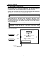
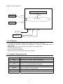
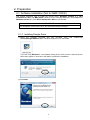
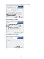
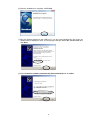
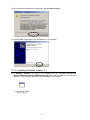

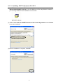
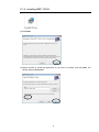

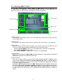

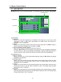

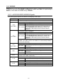
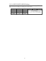
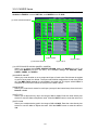
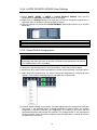
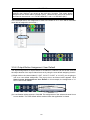
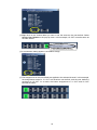
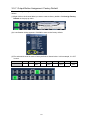
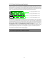
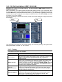
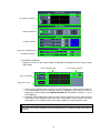
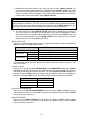
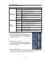

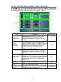
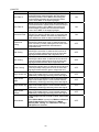
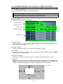
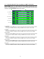
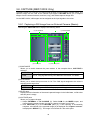
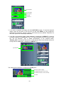
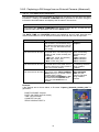
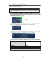
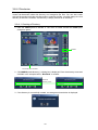

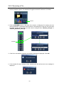
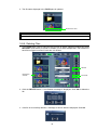
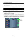
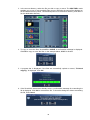
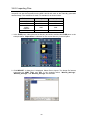
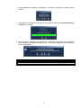
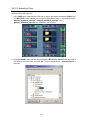
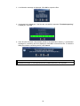
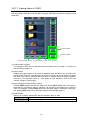
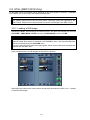
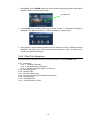
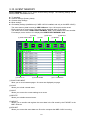
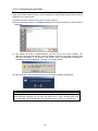
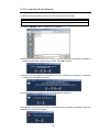
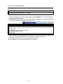
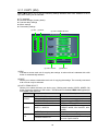
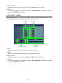
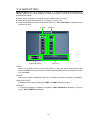
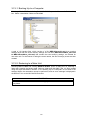
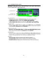

![MBP-12GUILE/12GUI取扱説明書[PDF:4.9MB]](http://vs1.manualzilla.com/store/data/006623918_2-b495e49e932502c0d2a50795758175dc-150x150.png)


![VTW Software Operation manual[PDF:17.4MB] - FOR](http://vs1.manualzilla.com/store/data/005725901_1-df2c6d7f9199f46fcf33ffa12e63545b-150x150.png)
![カタログPDFダウンロード[PDF:1.7MB]](http://vs1.manualzilla.com/store/data/006581727_2-bb010ce40f62d4b878607c76783fb901-150x150.png)