1
VAUXHALL Vectra
Owner’s Manual
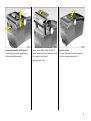
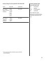
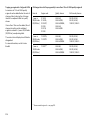
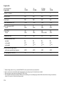
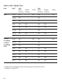
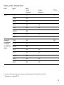
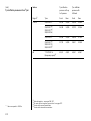
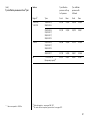
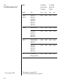
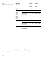
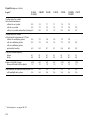
Data specific to your ve hicle
Please enter your vehicle’s data here to keep it ea sily accessible.
This information is available under the section "Technical da ta " as well as on the identification plate.
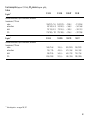
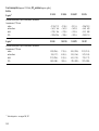
Fuel
Desi gnation
Engine oil
Grad e
Viscosity
Tyre inflation pressure
Tyre si ze
wi th up to 3 persons
Front
R ear
Front
R ea r
Winter tyres
Front
R ear
Front
R ea r
Weights
Permissible gross vehicle weig ht
–
EC k erb weight
=
Loading
Lev el control
Bump er H eig ht
0
wi th full load
Sum mer tyres
see page 179
Your Ve ctra
Dev eloped to the la test findings of vehic le research, it offers technical sophistication and exceptiona l comfort.
Your vehicle represents an ideal synthesis of ad vanced technolog y, outsta nding safety, environm ental compatibility and economy in
opera tion.
It now lies with you to drive your vehicle safely and to see it performs perfectly.
This O wner's Manual provides you with all the necessary information to tha t end.
The O wner's Manual should a lways be kept in the v ehicle: ready to hand in the g lov e com partment.
Make use of the Owne r's Manual:
z
z
z
z
z
Its “I n brief” section will giv e y ou an initial ov erview.
Its index will help you find what y ou want.
It will familiarize you with the sophisticated technology.
It will increase your pleasure in y our vehicle.
It will help you to handle y our v ehicle ex pertly.
The O wner's Manual is designed to be clearly laid-out and easily understood.
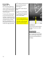
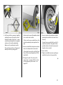
This symb ol:
6 signifies: continue reading on next page.
3 The asterisk sig nifies equipment op tions not in all vehicles (model variants, engine options, models specific to one country, op tional
equipment, Genuine Vauxhall Parts and Accessories).
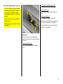
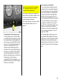
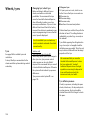
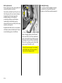
Text highlighted in yellow in p artic ular indica tes possible risk of accident and
injury. Disregard of these notes can lead to injuries which may b e fatal. Vehicle
passengers must b e informed accordingly.
Yellow arrows in the illustrations serve as points of reference or ind icate some action to be performed.
Black arrow s in the illustrations indicate a reaction or a second ac tion to be perform ed.
We w ish you m any hours of pleasurable driving
Your Va uxhall team
1
2
Contents
Comm itment to custom er
satisfaction:
Our ai m: to k eep you happy with your
vehicle. All Vauxhall Authorised Repairers
offer first class service at competitive
prices. Experienced, factory-trained
technicians w ork according to factory
instructions.Your Authorised Repairer can
supply you with GEN UINE VAU XHALLAPPRO VED PARTS , which hav e und ergone
stringent quality and precision chec ks, and
of course useful and a ttrac tiv e
VAUXHALL-APPROVED AC CESSO RIES.
Our nam e i s your guara ntee!
For d eta ils of the
Va uxhall Authorised Rep airer Netw ork
please r ing this number; 01582 - 427200
In b rief .. ..... .... ..... .... .... ..... .... ..... .... ..... .... .... . 4
Instrum ents ... ..... .... .... ..... .... ..... .... ..... .... .. 33
K eys, doors, b onnet .. ..... .... ..... .... ..... .... .. 54
S eats, Interior ..... .... .... ..... .... ..... .... ..... .... .. 69
S afety system s .. .... .... ..... .... ..... .... ..... .... .. 94
Lighting ..... .... ..... .... .... ..... .... ..... .... ..... .... 116
Windows, sun roof . .... ..... .... ..... .... ..... .... 120
C lim ate c ontrol .. .... .... ..... .... ..... .... ..... .... 126
Automatic transm ission . .... ..... .... ..... .... 144
C VTronic ... .... ..... .... .... ..... .... ..... .... ..... .... 150
Driving hints .. ..... .... .... ..... .... ..... .... ..... .... 158
S ave fuel, protec t the env ironment .... 160
Fuel consum ption, fuel, refuelling ... .... 162
C atalytic converter, exhaust gases .... 164
Drive control system s ..... .... ..... .... ..... .... 168
Brakes ... ..... .... ..... .... .... ..... .... ..... .... ..... .... 180
Wheels, tyres . ..... .... .... ..... .... ..... .... ..... .... 184
Roof racks,
caravan and tra iler towing . .... ..... .... 188
S elf-help .... .... ..... .... .... ..... .... ..... .... ..... .... 199
If y ou ha ve a problem .... .... ..... .... ..... .... 232
Maintenance, Inspec tion system .... .... 234
Vehicle care .. ..... .... .... ..... .... ..... .... ..... .... 245
Technical data .. .... .... ..... .... ..... .... ..... .... 250
Index . .... ..... .... ..... .... .... ..... .... ..... .... ..... .... 282
3
In brief
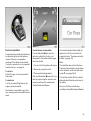
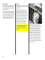
Key num be rs,
Code numbers
Remove key number from keys.
The key number is specified in the vehic le
docum ents and in the C ar Pass 3.
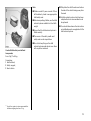
Alloy wheels 3, towing equipment 3: m ake
a note of the key identifier cod es.
Elec tronic imm obiliser, Radio 3 : the cod e
numb ers are specified in the Car Pass and
Radio Pass 3 respec tiv ely.
Do not keep the Car Pass and Ra dio Pass in
the vehicle.
6 Further information – see p ages 54, 55,
vehicle recomm issioning – see page 244.
4
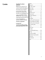
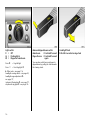
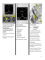
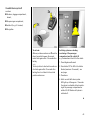
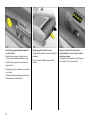
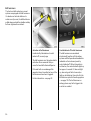
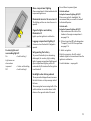
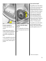
Unlock vehicle :
P ress button q or
turn ke y in driver’s side door lock,
pull door handle
O nce
Twice
=
=
Driv er’s door is unlock ed.
Entire v ehicle is unlocked.
The luggage
compartment is
autom atically reloc ked
after 5 minutes.
6 Door lock s, child sa fety lock –
see page 54,
electronic immobiliser – see page 55,
radio frequency remote control –
see page 56,
central loc king sy stem – see page 58,
anti-theft locking system 3 – see p age 58,
Vauxhall alarm system 3 – see page 63.
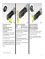
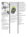
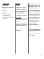
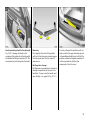
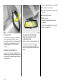
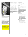
Unlock luggage compartme nt:
Press button r on rem ote control or
button x in the driver or
passenger door
The lug gage compartment is unlocked and
can be opened within 5 minutes.
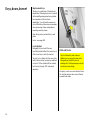
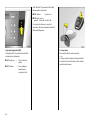
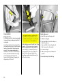
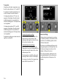
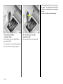
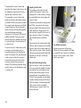
Front se at adjustment:
Pull handle,
slide seat,
release handle,
allow se at to audibly latch
into pos ition
If the luggage compartment is not opened
within 5 m inutes, it is automatically loc ked
again.
Nev er adjust the seat while driving. It could
move in a n uncontrolled manner when the
ha ndle is pulled.
The lugga ge c om partment is automatically
locked 5 minutes after closing.
6 Seat position – see page 69,
electrica lly adjusta ble front seats –
see p age 79.
6 Radio frequency rem ote control –
see page 56,
central lock ing – see page 58,
Vauxhall alarm system 3 – see page 63.
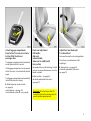
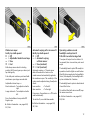
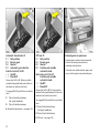
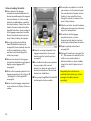
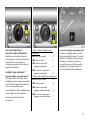
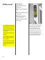
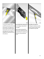
Adjust front seat backrests:
Turn handwheel
Move seat bac krest to suit sea ting position.
Do not lea n on seat back rest whilst
adjusting it.
6 Seat position – see p age 69,
electrically adjustable front seats –
see page 79.
Im porta nt : Do not sit nearer than 10
inches (25c m) from the steering wheel, to
permit safe airbag dep loy ment.
5
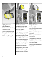
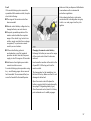
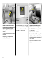
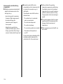
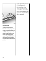
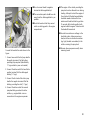
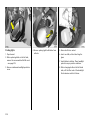
Adjusting front se at lum bar support:
Adjust leve r
Adjust lumb ar support to suit personal
req uirements.
Do not lean on sea t backrest whilst
adjusting it.
6 Seat position – see pag e 69,
electrically a djustable front sea ts –
see page 79.
6
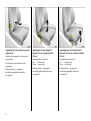
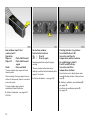
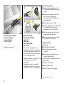
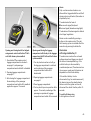
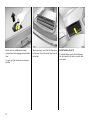
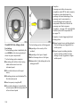
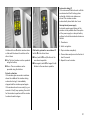
Adjusting front seat height 3:
Operate lever on outboard side
of seat
Adjusting front s eat inclination 3:
Ope rate front lever on outboard side
of s eat
Pump direction of the lever
Up:
Raises seat
Dow n: Lowers seat
Pump d irection of the lever
Up:
Inclines seat
Down: Lev els seat
6 Seat position – see page 69,
electrica lly adjusta ble front seats –
see p age 79.
6 Seat position – see p age 69,
electrically adjustable front seats –
see page 79.
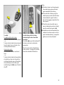
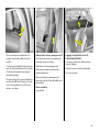
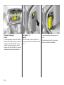
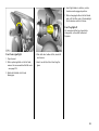
Ele ctric seat adjustm ent 3 :
Switch on outboard side of s eat
Front:
– Longitudina l adjustment,
– Height adjustment,
– Angle adjustm ent.
Middle:
– Backrest adjustment.
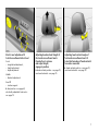
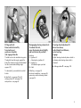
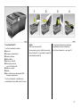
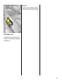
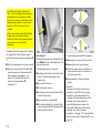
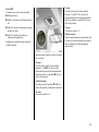
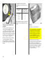
Adjusting head re straint height of
front and re ar outboard seats:
Pre ss button to release
and adjust he ight,
engage in position
6 Head restraint position – see page 70,
rear head restraints – see page 70.
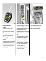
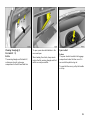
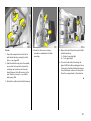
Adjusting head restraint angle of
front and rear outboard se ats 3:
Swive l bottom edge of head restraint
forward or rearward
6 Head restraint position – see pa ge 70,
rear head restra ints – see p age 70.
Rear 3:
– Lumbar support.
6 Seat position – see pag e 69,
electrically a djustable front sea ts –
see page 79.
7
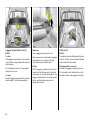
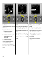
Adjusting interior m irror:
Swivel mirror hous ing
Adjusting exterior m irrors:
Four-way switch on driver’s door
Swing in e xterior mirror:
Swiv el lev er on underside of mirror housing
to red uce daz zle a t nig ht.
Press switch for left or right hand mirror:
four-way switch operates the
corresp onding m irror.
Electric 3 (both mirror switches must not b e
latched into position):
Autom atic anti-dazzle interior mirror 3:
Dazzle at night is automa tic ally red uced –
see page 114.
6 Position m emory 3 – see page 80.
Vehicles with electric seat ad justment 3:
if the mirror switch for the passenger side is
depressed when reverse gear is engaged ,
the passenger side ex terior mirror
repositions itself towards the rear tyres in
order to serve as mirror parking assistance
(not when tow ing a carav an / trailer).
Automatic anti-da zzle exterior mirror on
the driver’s side 3: dazzle at night is
autom atic ally reduc ed – see page 114.
6 Further information, aspherical exterior
mirror 3 – see pa ge 114,
heated ex terior mirrors – see page 20,
electric seat adjustment 3 – see page 79.
8
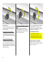
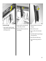
Manually: press lightly .
Push four-way switch to the right: ex terior
mirrors swiv el in.
Push four-way switch to the left: exterior
mirrors swiv el out.
The mirrors can a lso be swivelled in from
the outside: press button p on remote
control or turn key toward rear of v ehicle in
driver’s door lock and hold.
S wivelling only a llowed at speeds of up to
4 mph (7 km /h).
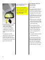
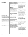
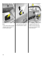
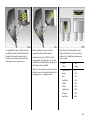
Fitting seat belt:
Draw se at be lt smoothly
from inertia ree l,
guide over shoulder
and engage in buckle
The b elt must not be twisted at any point.
The lap belt must lie snugly against the
body. The backrest must not be tilted bac k
too far (recomm ended tilting angle
approx. 25°).
To release belt, press red button on belt
buckle.
6 Seat belts – see pa ges 95 to 99,
airbag sy stems 3 – see p age 100,
seat p osition – see page 69.
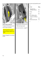
Disengaging steering column lock:
To re lease the lock,
move the s te ering wheel slightly
and turn the key to position I
Positions:
0 = Ignition off
I = Steering free, ignition off
II = Ignition on,
with diesel engine: pre-heat
III = Start
Steering whee l adjustment 3:
Move lever down,
adjust he ight and distance,
move lever up,
engage
Adjust steering wheel only when vehicle is
stationary and steering colum n loc k is
released.
6 Airb ag systems 3 – see page 100.
6 Starting – see page 23,
electronic im mobiliser – see pag e 55,
remove key and loc k steering w heel –
see p age 24.
9
10
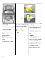
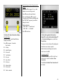
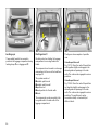
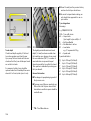
1
Page
Side air v ents ... ..... .... ..... .... .... ..... .... 129
2
Front pa ssenger airbag .... .... ..... ... 100
3
Centre air v ents .... .... ..... .... .... ..... ... 129
4
Radio 3
or Infotainm ent system 3 . .... ..... .... . 52
5
Central information display for
date, time, outside temperature,
Infotainm ent system 3,
radio 3 ,
check control 3,
trip computer 3,
electronic air conditioning
system 3 . ..... .... ..... .... ..... .... .... ..... .... . 41
6
Turn signals, hea dlight fla sh,
dipped and main beam ... .... ..... 16, 17
Door-to-door lighting 3 and
parking lights .. ..... .... ..... .... .... ..... .... . 17
Cruise control 3 .... .... ..... .... .... ..... .... 172
7
Remote control 3 for radio a nd
Infotainm ent system ..... .... .... ..... .... .. 30
8
Instruments .. .... ..... .... ..... .... .... ..... .... .. 33
9
Horn .... .... ..... .... ..... .... ..... .... .... ..... .... .. 18
10
11
Pa ge
Windscreen wiper and wa sh system,
headlight wash system 3 and
rear window wash system 3 .. ..... .... 19
Display op eration 3 . ..... ..... ..... ..... .... 48
Exterior lig hting ... ..... .... .... ..... .... ..... 116
Instrument illumination ... ..... .... ..... 117
Fog tail lig ht .... .... ..... .... .... ..... .... ..... 116
Front fog lights 3 ..... .... .... ..... .... ..... 116
Head lig ht range adjustment 3 ..... 117
Page
19 Heated seat (right) 3 . ..... .... ..... .... . 130
Anti-theft alarm system 3 .. ..... .... .. 63
Rear window blind 3 .. ..... .... ..... .... 125
Traction Control sy stem 3 .. ..... .... 168
Electronic Stability Program me 3 170
20 Ashtray s ..... .... .... ..... .... ..... .... ..... .... .. 90
21 Telematics 3 .. .... ..... .... ..... .... ..... .... .. 52
22 C igarette lighter 3 .. .... ..... .... ..... .... ... 89
23 Heating, ventilation,
air conditioning sy stem 3 ... ..... .... 126
Electronic air conditioning
system 3 ..... .... .... ..... .... ..... .... ..... .... 126
Auxiliary heating 3 .... ..... .... ..... .... 140
12
Stowage compartment
13
Bonnet release lev er .... .... ..... .... ..... . 68
14
Ignition lock
with steering wheel lock .. ..... .... ..... ... 9
15
Ac celera tor pedal .... .... .... ..... .... .... 158
16
Brake peda l ..... .... ..... .... .... ..... 159, 180
17
Steering wheel position adjuster .. ... 9
24 Heated seat (left) 3 and
seat climate control .... ..... .... ..... .... 130
Haz ard warning lights .... .... ..... .... .. 18
Parking distance sensors 3 . ..... .... 174
18
Clutch ped al 3 .... ..... .... .... ..... .... .... 159
25 Glove compartment
26 Fusebox . ..... .... .... ..... .... ..... .... ..... .... . 212
11
11
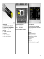
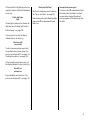
Control indicators
O
Turn sig na l light s:
see p ages 17, 33.
I
Oil p ressure:
see p age 33.
R
Brake system,
clutch system:
see p ages 34, 181.
p
Alternator:
see p age 34.
v
Airbag systems,
bel t tensioners:
see p ages 96, 105.
W
Coolant t em perature:
see p ages 34, 40.
X
Sea t belt 3:
see p age 35.
12
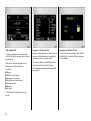
T
Autom atic t ransmission 3,
CVTronic 3,
wi nter program me:
see pages 147, 155.
y
Seat occup ancy recog nition 3:
see page 105.
m
Cruise control 3 :
see page 172.
!
Glow plugs 3:
see page 35.
Y
u
Anti- lock Bra ke Syst em :
see page 183.
Fuel level:
see pages 36, 40, 199.
Z
v
Exhaust emission 3:
see pages 36, 166.
Tract ion Control system 3,
Elec tronic St abili ty Progr amme 3 :
see pages 168, 170.
B
>
Adapt ive Forward Lig hting
(AFL) 3:
see pages 28, 118.
Front fog li ghts 3:
see pages 35, 116.
g
r
Fog tai l light:
see pages 35, 116.
Trailer turn signa l 3:
see page 36.
P
Mai n beam:
see pages 16, 35.
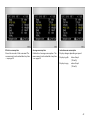
Display in tachometer
The following control ind ic ators will
illuminate as necessa ry :
o
Imm obiliser:
see p ages 37, 55, 166.
p
Electro-hydrauli c
power assisted steering :
see p age 37.
q
r
Hea dlight range adjustm ent 3:
see p age 117.
F
Brak e pad w ea r indica tor 3:
see pages 38, 180.
>
Front fog lights 3 :
see page 116.
S
Engine oil level:
see pages 38, 236.
r
Fog tail l ight:
see page 116.
H
Cool ant fluid lev el:
see pages 38, 239.
P
Main beam :
see page 16.
v
Serv ice interval display:
see page 234.
O
Tur n sig nal lig hts:
see page 17.
x
Tyr e p ressure control system 3,
loss of pressure w arning from the
respectiv e t yre:
see pages 38, 176.
k
Instrument il luminati on:
see page 117.
?
Hea dlight range adj ust ment 3:
see page 117.
b
Courtesy li ght:
see page 118.
c
Courtesy li ght deact ivat ion 3:
see page 118.
a
Reading li ghts, front 3 :
see page 118.
¨
Hazard w arning lig hts:
see page 18.
Pa rking d istance sensors 3:
see p age 174.
A
Engine electronics,
transmission elec tronics 3:
see p ages 37, 55, 166.
w
Tyr e p ressure control system 3,
fault :
see pages 38, 176.
s
Open lugga ge compa rtment:
see p ages 37, 61.
y
v
Airbag systems,
bel t tensioners:
see p ages 96, 105.
Doors open 3,
indi cating the r especti ve door:
see page 38.
t
Bul b replacem ent 3:
see p ages 38, 218.
Lighting
Light swi tch, stal k positi ons:
see pages 16, 116,
7
8
9
Lights off
Park ing lig ht s
Dipp ed and ma in beam
13
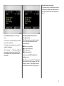
Climate control
x
Air flow:
see p age 127.
Air distri bution:
see p age 127,
L
to head area ab ov e ad justable
air vents and to footwell,
M
to head area ab ov e
adjustable air vents
front and rear 3,
l
to wind screen,
J
to wind screen and
to footwell,
K
to footwell.
V
Demi st ing and d efrosti ng 3:
see p ages 133, 137.
Ü
Hea ted rear wind ow:
see p age 128.
14
n
4
Air conditioning system 3:
see page 128.
d
Sun roof:
closing – see page 123.
ü
Sun roof:
opening – see p age 123.
see page 135.
f
Heated seats 3:
see page 130.
Sun roof:
comfort setting – see page 123.
e
Sun roof:
raising – see page 123.
Air reci rculati on system 3:
see page 128.
AUTOAutom atic m ode 3:
ß
Sun roof 3
A
Driv er’ s seat with clim ate control 3:
see page 130.
b
Remote cont rol of auxiliary
heating / v ent ilation 3:
see page 140.
Windscreen wiper
Stal k positi ons:
see page 19,
§
$
Off,
%
&
Slow,
Timed interv al wi pe, or automa tic
wipe w ith rain sensor 3,
Fast.
Date, time, information display, radio
)
Ciga ret te lighter 3 :
see page 89.
j
Horn:
see page 18.
/
Bonnet:
see page 68.
T
Wi nter program me,
automa tic tr ansm issi on 3,
CVTronic 3:
see pages 147, 155.
j
Selector lever lock ing,
automa tic tr ansm issi on 3,
CVTronic 3:
see pages 144, 151.
Chi ld safety sw itch 3 :
see page 121.
+
Fir st - aid k it 3:
see page 204.
N
Rear w indow b lind 3:
see page 125.
¨
Wa rning tri angle 3:
see page 204.
r
Park ing dista nce sensors 3:
see page 174.
Miscellaneous
Informat ion displa y:
see p age 41.
p
Centra l lock ing system:
locking – see page 58.
On button for date and time,
q
Centra l lock ing system:
unloc king – see pag e 58.
But tons on wiper stal k 3:
see p age 42.
r
Boot li d / tail gate:
unloc king – see pag e 61.
i
Trip computer,
forwards menu search,
x
h
Trip computer,
backwards menu search,
Luggag e c om part ment:
unloc king – see pag e 61.
m
§
Trip computer, select
Centra l lock ing switc h:
see page 59.
Ä
Anti- theft alarm system 3 :
see page 63.
z
Ö
;
Setting buttons for d ate and tim e.
Rem ote control 3 for radio
and Infota inment system:
see p age 30.
Cruis e control 3
But tons on turn signal sta lk:
see p age 172.
m
On, Accelerate,
g
Decelerate,
§
Off.
15
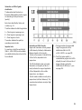
Light switch:
7 =
Off
8 =
Parking lights
9 =
Dipped or m ain beam
Press r
= Fog tail light
Press >
= Front fog lig hts 3
6 Other notes – see page 116,
head lig ht warning device – see page 24,
head lig ht ra nge adjustment 3 –
see page 117,
instrument illumination 3 – see page 117,
day tim e d riv ing lights 3 – see page 116.
16
Main and dipped be am switch:
Main be am
= P us h s talk forward
Dippe d beam = P us h s talk forward
again
You can also switch from main beam to
dipped bea m by pulling the stalk towards
the steering wheel.
Headlight flash:
P ull stalk towards s tee ring wheel
Operating door-to-door
lighting 1) 3:
Key to position 0 and rem ove,
ope n driver’s door,
pull turn signal s talk towards
steering whe el
Dipped beam and the reversing lights light
up for an add itional 30 seconds after the
driver’s door is c losed .
If the driv er’s door is left open, the lights will
go out after tw o minutes.
Door-to-door lighting can be deactivated
by inserting the k ey in the ignition sw itch or
by p ulling the turn signal stalk towards the
steering wheel aga in while the driv er’s door
is open.
1)
Operating turn signal lights :
Right
=
Stalk all the way up
Left
=
Stalk all the way down
The turn signal stalk returns to its orig inal
position after use. When the steering wheel
is straightened up, the turn signal lights are
autom atic ally cancelled.
Switch the turn signal off manually by
tapping the stalk.
When chang ing lanes, tap stalk until
resistance is felt: the resp ective turn signal
will flash three times.
Ope rating parking lights :
Light switch to position 0,
ignition key to position 0,
move turn signal stalk fully
upwards or downwards
As a check, a warning buzzer sounds and
the turn signal control indica tor on the
respective side illuminates.
To switch it off, switch on the ignition or
mov e the turn signal stalk in the op posite
direction.
Hold the stalk if y ou want the turn sig nals
to fla sh longer.
"D oor-to-do or" light function.
17
Cruis e control operation:
Press button on stalk
Switch on: ta p button m.
Switch off: tap button §.
Resume at stored speed: tap button g.
6 Cruise control 3 – see pa ge 172.
18
Hazard warning lights :
On = Press ¨
Off = Press ¨ again
To aid location of the pushb utton, the red
surface is illuminated when the ignition is
switched on. When the button is pressed,
its control indicator flashes in time with the
ha zard warning lights.
Sounding the horn:
P ress the ce ntre of the steering w hee l
6 Airb ag systems 3 – page 100,
remote control for radio and
Infotainment system 3 – page 30.
Winds creen wipe r:
Gently tap s talk upward
§ = Off
$ = Adjustable timed interval wipe
% = Slow
& = Fast
Stalk always mov es back to starting
position. Shift to next gear up or down: just
tap stalk g ently.
Push stalk pa st resistance point a nd hold:
windscreen wiper stages are selected .
Adjustable interva l wipe $:
Shorter interv als = Turn adjuster wheel to
right
Longer intervals = Turn ad juster wheel to
left
Press the stalk down from p osition §:
Single sw ipe.
6 Further inform ation – see pages 240,
241, 246.
Automatic wiping w ith rain sensor 3 :
Ge ntly tap stalk upward
§ = O ff
$ = Automatic wiping
w ith rain sensor
% = Slow (constant)
& = F as t (constant)
Automatic wiping $ : The rain sensor
detects the amount of water on the
wind screen and automa tica lly reg ulates
the windscreen wiper. The sensitivity of the
sy stem can be adjusted using the adjuster
wheel:
Less sensitiv e
= To the left
More sensitiv e
= To the rig ht
If necessary, the positions % or & ca n b e
selected manually.
To switch off, m ov e stalk d ow nwa rd s.
Ope rating w indscreen and
headlight wash systems 3:
P ull stalk towards s tee ring wheel
The wiper w ill swipe for a few strok es. At
low speeds, there is a one-time post-wash
swipe.
The headlight wash system 3 is ready for
operation when the lights are switched on.
Wash fluid is sprayed onto the headlights
(twice). Subsequently the headlight wash
system is b lock ed for 2 minutes.
The headlight wash system is deactivated
if wash fluid is low.
O n vehicles fitted with rain sensor 3, keep
the sensor area clean.
6 Further information – see pages 241,
242, 246.
6 Further information – see p ages 240,
241, 246.
19
Rear window wiper 3 and
wash system 3
Operation:
Wiper on
= P ush stalk forward
Wiper off
= P ush stalk forward
again
Wash
= P res s and hold
The rear window wiper swipes in timed
interval mode.
When washing , the w iper swipes for a few
strokes. At low speeds, there is a one-time
post-w ash swipe.
The rear window wa sh system is
deactivated if wash fluid is low.
6 Further inform ation – see pages 241,
242, 246.
20
He ated rear window,
heated ex terior mirrors:
On = Press Ü
Off = Press Ü again
Heating operationa l only with engine
running.
The rea r window and exterior mirror
heating is switched off a utomatica lly after
approx. 15 minutes.
6 Further information – see p age 128.
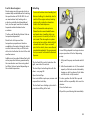
Clearing misted or icy windows:
Set air dis tribution to l,
turn rotary switches for
temperature and fan clockw ise
Air conditioning sys tem 3:
P ush V and n buttons,
turn rotary switch for
temperature clockwis e
O pen front air vents, direct side air vents
towards the door windows. Close centre air
vents 3.
6 Heating, ventilation, air conditioning 3 –
see page 126,
electronic air conditioning system 3 –
see page 134.
Setting e lectronic air conditioning
system 3 to autom atic m ode:
Press AUTO button,
set tempe rature for driver and
passenger sides us ing left and
right knobs
O pen all front a ir v ents. If desired , the rear
vents also 3.
6 Elec tronic air c onditioning sy stem 3 –
see page 134.
Information display:
Us ed to display information on:
–
–
–
–
–
–
–
–
Time,
outside temperature,
radio 3 and date,
navigation 3 ,
telephone 3 ,
chec k control 3,
trip comp uter 3,
electronic air conditioning 3.
6 Information disp la y 3 – see page 41.
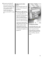
Manual transmission
o
= Neutral position
1 to 5 = 1s t to 5th ge ar
6
= 6th gear 3
When shifting up from 4th to 5th gea r:
push the lever towa rd s the right at the
beginning of the shift operation.
Between 5th a nd 6th gear 3 : push
gearshift lever to right in straight line.
When shifting from 5th to 4th gear:
do not exert any force towa rd s the left.
R = Reverse ge ar
Reverse gear: w ith v ehicle stationary , pull
the ring up three seconds after de-clutching
and engage gear.
If the gear does not enga ge, set the lever in
neutral, relea se the clutch pedal and
depress again; then repeat g ear selection.
21
Autom atic transmission 3:
P = Park position
R = Reve rse gear
N = Neutral
D = Automatic gear sele ction
Sele ctor lever in D to left:
+ = Upshift
- = Downshift
Always start in P or N. To leave position,
opera te brak e pedal and press button on
selector lever (selector lever lock ).
To enga ge P or R, push button on selector
lev er.
P:
R:
O nly with vehicle stationary ,
first a pply handbrak e
O nly with vehicle stationary
6 Automatic transmission – see p age 144.
CVTronic 3 :
P = Park pos ition
R = Reverse ge ar
N = Neutral
D = Continuously variable
automatic mode
Se lector leve r in D to le ft:
Continuously variable
automatic mode
+ = Upshift
- = Downshift
Alw ays start in P or N. To leave position,
op erate brake ped al and press button on
selector lever (selector lever lock).
To engage P or R, push button on selector
lever.
P: O nly with vehicle stationary,
first apply ha ndb rake
R: O nly with vehicle stationary
6 C VTronic – see pag e 150.
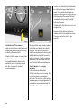
22
Exhaust gases are poisonous
Exhaust g ases contain ca rbon monox ide,
which is ex tremely poisonous but is
odourless and colourless.
Therefore never inhale exhaust gases, and
nev er run the engine in an enclosed space.
Before starting off, check:
z Ty re pressure and condition – see pag es
176, 184, 268.
z Engine oil level and fluid levels in engine
com partment – see pages 235 to 242.
z All windows, mirrors, exterior lighting
and num ber p la tes are free from dirt,
snow and ice and are operational.
z No objects are in front of the rear
wind ow, on the instrument panel or in
the area in which the airbag s inflate.
z Seats, seat belts and mirrors are
correctly ad justed.
z Bra ke op eration.
Starting, petrol engines :
Manual trans miss ion idling with
clutch pedal depres sed,
operate foot brake,
automatic trans miss ion or CVTronic
in P or N,
do not acce lerate,
turn key to pos ition III
The initially increased engine speed
autom atic ally falls as the engine
temperature rises.
Before repea ting the starting proc edure,
turn the key ba ck to 0 in the ignition sw itch,
remove it and then reinsert it. Then repeat
the starting proc edure.
Starting, dies el engine:
Manual transmission in neutral with
clutch pedal depresse d,
apply foot brake,
automatic transmission in P or N,
do not accelerate,
turn ke y to position II;
when control indicator ! goes out1),
turn ke y to position III
Before rep eating the starting procedure,
turn the key back to 0 in the ignition switch,
remove it and then reinsert it. Then repeat
the starting procedure.
6 Electronic im mobiliser – see pag e 55,
further inform ation – see pages 158, 199.
6 Electronic immobiliser – see page 55,
further information – see pag es 158, 199.
1)
Preh eatin g system sw itches on o nly if outside
tem perature is low .
23
Advice when parking:
z Alw ays apply hand brake firm ly. O n
slopes apply the ha nd brake as firmly as
possible.
z With m anual transmission, select first
gear or reverse, for automatic
tra nsmission 3 or CVTronic 3, place
selector lever in P.
z Close windows and sun roof 3.
z In vehicles with autom atic transmission 3
or CVTronic 3 the key can only be
removed in selector lever p osition P.
Rele as ing the handbrake:
Raise leve r s lightly,
pre ss lock button,
lower le ver fully
6 Bra kes - see pag e 180
Parking the vehicle:
Apply handbrake firm ly,
engine off,
rem ove ke y,
lock s te ering wheel,
lock ve hicle
To lock , press button p or turn key
anticlock wise in the lock. To activate the
anti-theft lock ing sy stem 3 and anti-theft
alarm system 3, press button p twice or
turn key anti-clockw ise twice.
6 Further information – see p ages 55, 158,
ra dio frequency rem ote control –
see p age 56,
central locking system – see page 58,
Vauxhall a la rm system 3 – see pag e 63,
vehicle dec om missioning – see page 244.
z Turn steering wheel until y ou feel loc k
engage (anti-theft protection).
z Engine cooling fan m ay run on after the
engine has been switched off.
Warning buzze rs
While driving:
z If seat belt is not fa stened1 ),
z If a specified ma ximum speed is
ex ceeded1 ),
z If the luggag e com partment is open
when the vehicle starts off.
When the vehicle is parked and the driv er’s
door is opened:
z If the k ey is inserted 3,
z If ex terior lights a re on,
z If the turn signa l stalk is engaged.
1)
24
Co untry-specific version.
Ge nuine Vauxhall P arts and
Accessories
We rec om mend "Genuine Vauxhall Parts
and Accessories" and conversion parts
relea sed expressly for your vehic le typ e.
These parts have undergone special tests
to establish their reliability, safety and
specific suitability for Vauxhall v ehicles.
Despite continuous market monitoring, w e
cannot a ssess or guarantee these
attrib utes for other prod ucts, even if they
ha ve b een granted a pproval by the
relev ant authorities or in some other form .
Service work, mainte nance
We recomm end tha t you entrust all w ork to
a Vauxhall Authorised Repa irer, who ca n
provide you with relia ble serv ice and
correctly perform all work according to
factory instructions.
6 If you have a problem– see pa ge 232,
service interval display – see pa ge 234.
"Genuine Vauxhall Parts a nd Accessories"
and conversion p arts app rov ed by
Vauxhall can be ob ta ined from a Vauxhall
Authorised Rep airer, of course. Here y ou
will be given comprehensiv e ad vice a bout
permitted technical changes and c orrect
installation w ill ta ke p la ce.
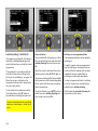
That was the most important
inform ation for your firs t drive
in your V ectra.
The othe r pages of this chapte r
contain a sum mary of the other
intere sting functions in your vehicle.
The rem aining chapters of the
Ow ner’s Manual contain important
inform ation on operation, safety and
maintenance as we ll as a complete
index.
For your s afety
C arry out regularly the check s
rec om mended in the indiv idual sections
of this Owner’ s M anual.
Ensure that your v ehicle is serviced at the
service intervals spec ified in the Serv ic e
Booklet. We recommend that y ou entrust
this work to a Vauxhall Authorised
Repairer.
Hav e faults remedied without d elay!
C onsult a workshop. We recommend a
Vauxhall Authorised R epairer. If
necessary , interrupt your journey.
6 Maintenance – see page 234.
25
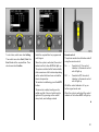
External w indow and sun roof 3
ope ration 3
Press button q or p on the remote control
until the windows are open or closed,
respectively .
Press button p on the remote control until
the sun roof is closed.
If the rain sensor 3 detects w ater with the
mechanic al anti-theft locking system 3
activated, a ll electronic w indows and the
sun roof are closed. The windows and the
sun roof are also automa tic ally closed after
four hours.
6 Further inform ation – see pages 122, 124.
Position m emory 3 for ele ctrically
adjustable drive r’s seat,
exterior mirrors and ins ide rear view
mirror
Storing setti ng s
1. Adjust seat and mirror,
2. Press m emory button M a nd the position
button to be used (1, 2 or 3)
simulta neously. Storage is
ack nowledged by an acoustic signal.
Ret rieving setting s
Press and hold down position buttons 1, 2
or 3, until stored p ositions hav e been
reached .
Ad justments may only be performed with
vehicle stationary.
6 Further information – see p age 69.
26
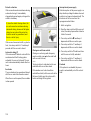
Heated se ats 3,
driver’s s eat with climate control 3
O perate the a djuster wheels beneath the
centre air vents and buttons on the rear of
the centre console.
For the front seats, set knurled wheels to
required ventilation setting 3 or heater
setting as per requirements. For rear
outboard seats, p ress buttons.
6 Further information – see page 130.
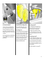
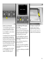
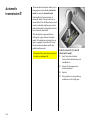
Travel As sistant 3
The Trav el Assistant contains:
z
z
z
z
z
z
armrest,
stowage compartm ents,
waste container,
drink holders,
accessory sock ets,
connection console
e.g. for DVD p la yer 3,
z elec tric cool box,
z ta bles,
z tw in aud io (rear audio module) 3 or
stowage compartm ent.
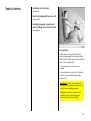
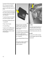
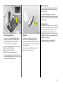
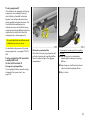
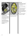
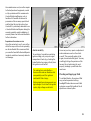
Ta bles
Fold arm rest upward (1).
Set req uired clea ra nce by adjusting
longitud inal p osition of tab le (4).
Use recessed grip to p ull tab le upward as
fa r a s it will go (1), sw iv el table forw ard (2)
and fold downward (3).
6 Further information – see page 72.
The Trav el Assistant is installed on a
console above the m iddle seat in the rear.
27
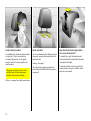
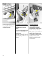
FlexOrganize r 3
The side walls house a ttac hm ent rails that
can be used a s necessary for different
systems to divide the lugg age
compartment or secure load s.
The system consists of:
z variable partition net
z variable partition w all
z partition rod
z mesh pockets for the side walls
z hooks
6 Further inform ation – see page 86.
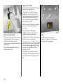
Adaptive F orward Lighting (AF L) 3
On vehicles with Bi-Xenon headlights,
improves illumination of
z curves (curve lighting ),
z intersections and tight turns (turn
lighting).
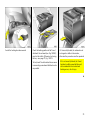
C ur ve lighti ng
The Xenon light b eam pivots based on
steering wheel position and speed (from
app rox . 6 mph / 10 km/h).
The headlights shine at an angle of up to
15° to the right or left of the direction of
travel.
Turn lig hting
An additiona l light is switc hed on based on
steering wheel position (when turned past
app rox . 90°), turn signal use and speed (up
to app rox . 25 mph / 40 k m/h).
The lig ht shines at an a ngle from app rox .
90° to the left or right of the v ehicle up to a
distance of a pprox. 30 metres.
6 Further information – see page 118.
28
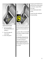
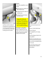
Operating the
graphical inform ation display 3
or the colour information dis play 3
Usi ng multi func tion butt on
Push
C onfirm / select
Rota te
Move in menu
Using but tons on wiper stalk
Rear button:
§ Activate / confirm / select
6 Further information – see p age 42.
Front buttons:
h Move up in the menu
i Move down in the menu
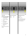
Trip computer 3
The trip computer shows vehicle data
which it continua lly records and evaluates
electronically.
Functions:
z Range,
z Effective consum ption,
z Average consum ption,
z Instantaneous consumption,
z Average speed,
z Distance,
z Settings.
6 Further information – see page 48.
29
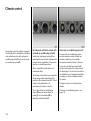
Check control 3
Check control monitors several fluid levels,
the tyre pressure 3 , the radio frequency
remote control battery, the anti-theft alarm
system 3 and imp ortant external lights,
including the cables and fuses. In trailer
mode the trailer lig hting is a lso monitored.
6 Further inform ation – see page 46.
30
Re mote control for radio and
Infotainment system 3
Radio 3, radio telephone 3 and
Infotainment sy stem 3 functions ca n be
op erated with the b uttons on the steering
wheel.
For further inform ation, see the respectiv e
op erating instructions.
Twin Audio 3
Twin Audio provides rear seat oc cup ants
the op portunity to listen to a different
audio sourc e than the one selec ted b y the
driver.
Two headp hone connec tions a re available
with sepa ra te volume control.
For further information, see the respective
radio operating instructions.
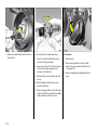
Active he ad res traints 3
Vauxhall Full-Size airbag system
In the event of a rear-end impa ct, the
active head restraints automatically tilt
forwards. The head is more effectiv ely
sup ported by the head restraint and the
danger of hyp erex tension in the neck area
is reduced.
The Vauxhall Full-Size airbag sy stem
comprises severa l ind ividual systems.
Active head restraints are id entified by the
lettering ACTIVE on the head restraint
guide bushes.
Front a irbag system
The front airbag sy stem will b e triggered in
the event of a serious accident inv olv ing a
frontal impa ct and forms sa fety cushions
for the driver and front passenger. The
forward movement of the driver a nd front
passenger is check ed a nd the risk of
injuries to the up per body and head
thereby substantially reduced.
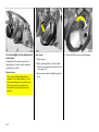
Si de airba g system 3
The side airbag sy stem triggers when a
side-on collision occurs and provides a
safety barrier for the driver a nd/or
passenger in the respective front door
area. This reduces the risk of injury to the
upper body considera bly in case of a side
impa ct.
C ur tain ai rbag syst em 3
The curtain a irba g system triggers in case
of a side-on collision and provid es a safety
barrier in the hea d area on the respective
side of the vehic le. This reduces the risk of
injury to the hea d considerab ly in case of a
side-on collision.
6 Further information – see page 100.
31
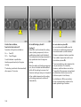
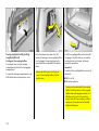
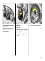
Parking distance se nsors 3
ECOService -Fle x
The p arking dista nce sensors front and
rea r sy stems are automatically sw itc hed on
when d riv ing in reverse gear.
The oil change and service intervals are
flexible, based on a number of different
parameters and the conditions under
whic h the vehic le is used. Various enginespecific data is continuously recorded and
used to calculate the rem aining distance
up to the next inspection date.
The p arking dista nce sensors ca n also be
switched on and off m anually using the r
button on the instrument panel.
If the vehicle approaches a n ob stacle to
the front or rea r, a series of signals is
sounded in the vehicle interior. The interval
between the signals becomes shorter a s
the d istance is reduced. If the dista nce is
less than 30 cm , the signal will b e
continuous.
6 Further inform ation – see page 174.
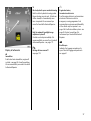
32
The rem aining driving dista nce can b e
seen in the tachom eter disp la y when the
ignition is off: press the reset b utton und er
the trip odometer; v and the remaining
driving dista nce will then be display ed.
With the specially developed engine oil for
vehicles with EC OS ervice-Flex, the nex t
eng ine oil change is due after a maxim um
of 2 years or 25,000 m iles / 35,000 k m
(petrol engine) or after a max imum of 2
y ears or 30,000 miles / 50,000 km
(diesel engine)
When topping up the oil, alwa ys use grade
GM-LL-A-025 or GM-LL-B-025 in order to
ma intain the flexible maintenance
interva ls.
6 Further information – see pages 234, 251.
Instruments
Control indicators
The c ontrol indicators described here are
not present in a ll v ehicles. The descrip tions
howev er, a pply to all instrum ent versions.
Some control ind icators are shown a s
pictograms within the tachometer d ia l
area.
O
Turn signal l ights
The c orresponding control indicator
flashes when the turn signal is on. If the
hazard warning lig hts are activated, both
control indica tors flash. Rapid flashes: a
turn signal b ulb or its associated fuse has
failed. Changing bulbs – see p age 218,
fuses – see page 212.
I
Oil p ressure
Control indica tor lights up when ignition is
switched on. Goes out shortly after eng ine
starts. C an light up intermittently when
idling with hot engine; must g o out w hen
engine speed is increased.
Lights up when the engine is running :
Engine lub ric ation may be interrupted . This
may result in dam age to the engine and/or
lock ing of the drive wheels:
1. Depress clutch.
2. Shift transm ission to idling , with
automatic transmission 3 or C VTronic 3
move selector lever to N.
3. Steer as quickly as possible out of the
stream of traffic, without imped ing other
vehicles.
4. Switch the ig nition off (Position I).
When the ignition is off, c onsiderab ly
more force is needed to brake and steer.
Do not remove key until vehicle has
come to a stand still, otherwise the
steering column lock c ould engage
unexpectedly .
C heck oil level before consulting a
workshop. We recommend a Vauxhall
Authorised Repa irer.
33
v
Airb ag system s 3 ,
belt tensioners 3
see pages 96, 105.
W
C ool ant temp era ture
Lights up when the engine is running:
S top vehicle and switch off engine. C oolant
temperature is too high: switch off engine.
Danger to engine. Coolant fluid
temperature disp lay – see page 40.
C heck the coolant level immediately –
see page 238.
R
p
Brak e system ,
clutc h system
The control indicator lights up when ignition
is switched on if handbrake is applied or if
brake / clutch fluid level is too low. Further
information – see pages 181, 240.
Alternator
Control indica tor lights up when ignition is
switched on. Goes out shortly after eng ine
starts.
If it lights up when the handbrak e is not
applied: stop the vehicle; interrupt your
journey immediately . Consult a
work shop. We recom mend a Vaux ha ll
Authorised Repairer.
34
Lights up when the engine is running :
Stop, switch engine off. Battery is not
cha rg ed. Engine cooling m ay not be
op erating. With a diesel eng ine, the brake
servo unit may stop operating . Consult a
work shop. We recommend that y ou consult
a Vaux hall Authorised Repairer.
X
!
r
Seat b el t 3
The c ontrol indicator lights up when the
ignition is switched on and rem ains lit until
the seat belt is fastened. An a coustic signal
is also emitted when the car starts to move.
Fastening seat belt – see page 98.
Preheating 3 for diesel eng ines
Control indica tor lights up during
prehea ting.
Fog tai l light s
C ontrol indicator lights up when fog tail
light is switc hed on.
Preheating system switches on only if
outside temperature is low.
P
T
Winter progr amme w ith autom atic
tra nsm ission 3 or CVTronic 3
Control indicator lights up when winter
programme selected.
Further information – see pa ges 147, 155.
u
Anti-lock Brak e S ystem 3
see p age 182.
v
Tr action C ontrol system 3,
Electronic Stab ility Program me 3
see p ages 168, 170.
>
Front fog lights 3
Control indica tor lights up when front fog
lig hts are switc hed on.
Ma in beam
C ontrol indicator lights up when ma in
beam is on and w hen headlight flash is
operated.
y
Seat occupancy recogniti on 3
see page 105.
m
C ruise cont rol 3
see page 172.
35
B
Ad aptiv e Forwa rd Lighting (AFL) 3
Fault in sy stem. C onsult a workshop. We
recommend a Vauxhall Authorised
Repairer.
AFL – see page 118.
g
Trai ler turn signal li ght 3
C ontrol indicator flashes in tim e w ith turn
signal lights when towing. Does not fla sh if
a turn signal light on the towing vehicle or
trailer fa ils.
Y
Z
Fuel l ev el
Lit: low fuel level. Fuel gauge in reserv e
area.
Exhaust gases 3
Control indica tor lights up when ignition is
switched on. Goes out shortly after eng ine
starts.
If it flashes: fuel used up, fill up immediately.
Never let the tank run dry!
Petrol eng ines: erratic fuel supply can
cause ca talytic converter to overheat –
see page 164.
Diesel engines: if the tank is run d ry , bleed
the fuel sy stem as described on pag e 199.
36
Lights up when the engine is running :
Fault in emission control system . The
permitted em ission limits m ay b e
exc eeded. Consult a workshop. We
recommend a Vauxhall Authorised
Repairer.
If it flashes when the engine is running:
For fa ult that ca n lea d to destruction of the
catalytic converter – see page 166. C onsult
a workshop immediately. We recommend
that you consult a Vauxhall Authorised
Repairer.
p
A
Electro-hydrauli c power a ssisted steering
Fault in electro-hydraulic steering system .
Power steering may not work. Vehicle c an
still be steered, but considera bly more
force is required . We recommend you
consult a Vauxhall Authorised Repairer.
Engine el ect ronics,
tra nsm issi on electr oni cs
Fault in engine electronics or transm ission
electronics. Electronics switch to
emergency running programme. Fuel
consum ption may increase and driveability
of the vehicle may be impaired – see
pag e 166. Fault in imm obiliser system – see
pag e 55. Contact a workshop. We
recommend your Vaux hall Authorised
Repairer.
?
Fault in autom atic head light ra nge
adjustm ent syst em 3
Contact a workshop immediately . We
recommend that you consult your Vauxhall
Authorised Repairer – see page 117.
Display in tachometer
o
Im mobil iser
Fault in electronic immobiliser, engine w ill
not start – see page 55. Consult a workshop.
We recommend tha t you consult a Va ux hall
Authorised Repairer.
r
Pa rking distance sensors 3
see p age 174.
s
Bootli d open
Indicates the luggage compa rtm ent is
open. Close the luggage compartment –
see page 61.
37
v
S
w
Airb ag systems,
belt t ensioners
see pages 96, 105.
Engine oil l ev el
Engine oil level too low . Check engine oil
level at the first opportunity . Engine oil
level – see pa ge 236.
Tyre p ressure control syst em 3,
fault
see page 176.
Bulb repl acement 3
A bulb has failed . C heck the lights, and
exchange the failed bulb . Bulb exchange –
see page 218.
H
O pen doors
Indicates tha t one or more doors is open.
C lose all doors.
F
v
t
Brak e lining wear indicat or 3
Front disk b ra ke pad worn to minimum
thickness. Contact a workshop to hav e
the b ra ke pads changed. We recommend
that you contact a Vauxhall Authorised
Repairer – see page 180.
38
Coolant lev el
Coolant level too low, check the coolant
level immediately – see pa ge 239.
y
P, R, N, D, 1 to 5
Service interv al
see p age 234.
Automat ic transm ission 3,
S elec tor lever position or mode selected see page 146.
x
P, R, N, D, A, 1 to 6
Tyre pressure contr ol system 3,
loss of p ressure warning
Check the pressure of the respec tiv e ty re
immed iately – see page 176.
C VTronic 3,
S elec tor lever position or mode selected see page 153.
Odometer
Records the miles / kilometres driven.
Trip odometer
To return to zero, depress reset k nob with
ignition switched on.
Service interv al display – see pa ges 32, 234.
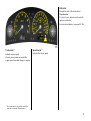
Tachometer 1)
Spee dome ter 1)
Indicates engine speed.
Indicates the vehicle speed .
Warning zone: m aximum permissible
engine sp eed ex ceeded ; danger to engine.
1)
The instrum ents in yo ur vehicle m ay d iffer
from the instrum ents illustra ted here.
39
For physical reasons, the engine
temperature gauge show s the coolant
temperature only if the coolant level is
adeq uate.
During operation the system is pressurised.
The temp erature ma y therefore rise briefly
to ov er 100 °C.
Coolant te mperature display
Fuel gauge
Pointer in zone
at left
Pointer in left
zone or Y lit
Pointer between
the z ones
Pointer in
warning zone
at right
or W is lit
40
= Engine operating
tem perature not
yet rea ched
= Normal operating
tem perature
= Tem perature
too high:
Stop, switch off
engine, danger to
engine, check
coolant lev el
immediately – see
page 239.
Pointer in left
zone or Y
flashing
= Reserve area
= Fill up –
see pag e 163
N ever run the tank dry !
Because of the fuel remaining in the tank,
the amount of fuel required to fill the tank
ma y be less than the spec ified tank
cap acity.
Inform ation display
Tripl e inform ation d isp lay
Display of time, outside tempera ture and
radio / date.
The tim e and outside temperature are
displayed when the ignition is on. The date
is disp layed when the radio 3 is switched
off.
When the ignition is off, the time, date and
outside tem perature can be presented for
15 second s b y briefly pressing one of the
two buttons b elow the displa y.
Display of --.- °C or F in the d isplay
indicates a fault. H ave the cause rem edied.
We recommend that you consult a
Vauxhall Authorised Repairer.
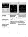
Graphica l informa tion displa y 3 ,
Colour inform ation di sp lay 3
Display of date, time, outside tem perature,
and informa tion from check control 3,
trip computer 3 , electronic air conditioning
sy stem 3, radio 3 and Infotainment
sy stem 3.
The g ra phica l inform ation display presents
the information in monochrom e. The colour
information display p resents the
information in colour.
The information d isplay ed depends on the
vehicle equipment and the settings of the
trip comp uter 3, the electronic air
conditioning system 3, the radio 3 and the
Infotainment system 3.
Electronic air conditioning system – see
pag e 134. For operation of the radio and
Infotainment system refer to the
acc om panying opera ting instruc tions.
Display of --. - °C or F in the displa y
indicates a fault. Have the cause remedied.
We recommend that you consult a
Vauxhall Authorised Repairer.
41
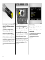
Operating the graphical information
display 3 or the colour information
display 3
The functions are activated using the
buttons on the wiper stalk or b y using the
multifunction button if the vehicle is
equipp ed with a radio telephone 3 or
Infotainm ent system 3 – see Fig. 12824 J.
If chec k control issues a warning message,
the display is blocked from other func tions.
Acknowled ge the message with button §
on the wip er stalk 3 or by p ressing the
multifunction button. If there are severa l
fault warnings, ack nowledge them one a t a
time.
42
The trip computer functions a re activated
using the m enus on the disp lay and the
buttons on the wiper sta lk 3 or via the radio
telep hone 3 or Infota inm ent system 3 .
Ac tiv ation using buttons on wiper stalk:
The individual menu items are selec ted
using the h and i buttons and selected
by pressing the § button. To activa te the
trip computer, press the § button.
Ac tiv ation using multi-function button: the
indiv idua l menu items are selected by
rotating and selected b y pressing. Press BC
button on system to activate the trip
computer.
System settings
The figures show execution with the colour
inform ation display .
In the trip computer settings menu, select
System Setti ngs.
O n vehicles without trip comp uter, press
button § on the wiper stalk 3.
The sy stem settings menu will b e
displayed.
Language selec tion
You ca n select the display language for
som e functions.
Select the required lang uag e from the list.
Selections are indicated by a 6 in front of
the menu item.
Sett ing units of measure
Y ou can select which units of mea sure are
to be used.
In the System Set tings menu, select item
Instruct ions.
In the Syst em Settings m enu, select item
Unit s.
The list of availab le languages will be
displayed.
S elec t from the list of units that opens.
S elec tions are indic ated b y a 6 in front of
the menu item.
43
Set displa y m ode
The display can b e adjusted to suit the light
conditions, b la ck or coloured text on a light
background or white or coloured text on a
dark bac kground.
In the System Setti ngs menu, select item
Automat ic, Day or Ni ght.
Automat ic: Adjustment depending on
vehicle lighting.
Da y: Black or coloured text on light
background.
Night: White or coloured text on dark
background.
Adj ust contrast
In the System Set tings menu, select item
Cont rast.
The c ontrast menu w ill be d isplay ed.
Confirm the required setting.
Setting date and time
In system s w ith a GPS receiver 1)
(Infotainm ent system 3, radio telephone
with GPS m od ule 3) the tim e and da te are
automatically set when a GPS satellite
signal is received . If the displa yed time
does not ma tc h the local tim e, the time can
be corrected by making manual entries in
steps of 30 minutes or autom atically by
receiving a n RDS time signa l2) 3 .
In rad ios without a GPS receiv er, the time
and d ate c an be adjusted manually or
automatically using the RDS time signal 3.
S om e RDS transmitters d o not send correct
time signa ls. If the incorrect tim e is
displayed often, d eactiva te the automa tic
time synchronisation 3 and set the time
ma nually.
The autom atic setting is ind ic ated b y Ö in
the display .
1)
2)
44
GPS = G lob al P osition in g System,
Satellite system for world -wide p osition in g.
RDS = R a dio Da ta System.
Deactivating a nd activating automatic
setting
Hold down Ö for approx. 2 sec., c lock
display is now in setting mode.
Press Ö twice (until y ear flashes).
Press and hold down Ö for ap prox .
3 seconds until } flashes in display a nd
text " RDS TIM E" a ppears (years fla sh
during this time).
Display indicates:
RDS TIME 0 = Deactivated
RDS TIME 1 = Activa ted
Press Ö three times.
Vehi cles w ith tri ple informat ion displa y
Manual setting
Switch off radio. Press Ö and ; below
display a s follows:
Vehicles with gr aphical informat ion
di sp lay 3 or colour inform ation d isp lay 3
In the Syst em Settings menu, select item
Tim e / Date.
Press Ö for ap prox . 2 seconds:
Day fla shes
;: Set day
The menu for time / date will be display ed.
Ö : Month fla shes
;: Set month
Ö : Year flashes
;: Set year
Ö : Hours flash
;: Set hours
Ö : Minutes flash
;: Set minutes
S elec t the menu items required.
Mak e the desired setting s a nd confirm.
S elec t menu item O K.
C orrecting time 3
To correc t the time, use RDS in the Time /
Date menu to select item Auto. Ti me
C orrec tion.
The field behind Auto. Time Correcti on will
be ticked.
Ö : Clock is started.
45
Check control 3
Check control monitors several fluid levels,
the tyre pressure 3, the radio frequency
remote control ba tteries, the anti-theft
alarm system 3 and im portant external
lig hts, including the cables and fuses. In
tra iler mode, the tra iler lighting is also
monitored.
Once the ignition has been switched on, all
check control functions are autom atically
verified .
Fault warnings appear on the display. If
there a re sev eral fault warnings, they are
display ed one after the other.
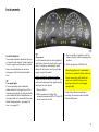
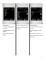
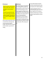
Outs ide tempe rature
A fall in temperature is indica ted
immediately and a rise in temp erature
after a time delay .
O n v ehicles with trip le inform ation display,
the sym bol T is shown in the disp lay from
3 °C as a warning for icy road surfaces.
O n vehicles w ith g ra phic al information
display 3 or c olour information displa y 3 a
message is shown in the display to warn for
icy road surfaces. See figure.
Caution: The road surface may already
be icy even though the display indicates
a few degrees above 0 °C .
46
Some of the fault warnings appea r on the
display in an abb reviated form.
Ac know ledge fault displays as described
on p age 42.
Fault warnings:
Check r em ote control
batt ery
If battery volta ge of the remote control unit
is too low – see page 57.
Check b rake lig ht switch
Fault. Brake light does not come on when
brak e ap plied. Have cause of fault
remedied imm ediately. We recom mend
that you consult a Vaux hall Authorised
Repairer.
Check sa feg ua rd
Fault. Sy stem error in a nti-theft alarm
system. Have cause of fault remedied
imm ediately. We recomm end that y ou
consult a Vaux ha ll Authorised Repairer.
If there is a fault in the lighting sy stem, the
respective location of the fault is displayed
as tex t, e.g.:
C heck right brak e
light
If brak e light is defective, the relev ant tail
light takes ov er the brake light function.
Check w ash fluid level
Fluid level in wind screen wash system too
low . Top up wa sh fluid – see p age 242.
Rear window wash sy stem 3 and headlight
wash system 3 a re deactivated if wash
fluid is low.
I nt err up tion of pow er supp ly
The check control 3 autom atically checks
all functions after the battery has been
reconnected or c ha rg ed. Stored fault
warnings appear on the display one after
the other.
Bulb exchange – see page 218.
If tyre pressure is too low, the disp lay
indicates the tyre to check, e. g.:
Check rear r ight
t yre pressur e
Check ty re pressure at next opportunity,
using suitable tyre pressure gauge. Tyre
pressure control sy stem 3 – see page 176.
Checking tyre pressure – see p age 184.
If there is major loss of pressure in a tyre,
the d isplay indicates the tyre a t fault, e. g.:
R ear left tyr e
pressure loss
Stop im med ia tely a nd check tyre. Tyre
pressure control sy stem 3 – see page 176.
47
Trip computer 3
The trip computer show s v ehicle data
which it continually records and evaluates
electronic ally .
Some of the functions a ppear on the
display in a n abbrev iated form.
Functions:
z Rang e,
z Effective consump tion,
z Av erage consump tion,
z Instantaneous consumption,
z Av erage speed,
z Distance,
z Settings.
Check control warnings a lways have
priority.
48
Range over 30 m iles (50 km)
Range is calculated from current fuel ta nk
content and instantaneous consumption.
The display shows avera ge v alues.
The ra nge updates automatically after a
brief delay after the v ehicle has b een
refuelled. Manual updating is also possible –
see page 50.
Ra ng e b el ow 30 m iles (50 km)
If the fuel in the tank will allow less than 30
miles (50 km), a warning "Range" appears
on the display .
Effect ive consumpt ion
Shows the a mount of fuel consumed . The
measurement can be restarted at any time
– see pa ge 50.
Average consumpt ion
Calculation of avera ge c onsumption. The
measurement c an be restarted at any time
– see page 50.
I nsta ntaneous c onsump tion
Display c hanges depending on sp eed:
Display in g al/h
below 8 m ph
(13 km /h),
Display in m pg
above 8 mph
(13 km /h).
49
Averag e sp eed
Average speed calculation. Measurement
can be restarted at any time,
see right-hand column.
Stoppag es in the journey with the ignition
off are not included in the ca lc ulations.
Di st ance trav ell ed
Display s number of miles (kilometres)
driven. Measurement can be restarted at
any time, see right-ha nd colum n.
Reset current trip comput er i nformati on
The following trip com puter inform ation
can b e reset (restart measurements):
z
z
z
z
z
Range (only with vehicle stationary),
Effective consum ption,
Average consum ption,
Average speed,
Distance travelled.
S elec t the required items from the trip
computer menu.
Then select menu item Settings.
The Settings menu is displayed.
50
I nt err up tion of pow er supp ly
If the power supp ly has been interrupted or
if the battery voltage ha s dropped too low,
the values stored in the trip computer w ill
be lost.
Select BC Reset present in the Settings
menu.
The v alue for the selected function will b e
reset and reca lculated.
The range values can only be reset if the
vehic le is stationary.
After resetting, "- - -" is displayed with the
trip computer information selected. The
reca lculated v alues are d isplay ed after a
brief delay .
Resetting multip le informat ion on
the trip com puter
The follow ing trip computer information
can be reset simultaneously (restart
measurements):
z
z
z
z
Effective consumption,
Average consumption,
Average speed,
Distanc e travelled.
Select menu item BC Reset all in the
Settings menu.
The v alues are reset a nd "* **" is d isplay ed.
New values are only displayed when the
engine is running. The av erage speed is
calculated shortly after starting to drive.
51
As the vehicle aeria l is relatively near the
ground, the broadcasting compa nies
cannot g uarantee the sa me quality of
reception a s is obtained with a domestic
ra dio using an ov erhead aerial.
z C hanges in distance from the
transm itter,
z Multi-path reception due to reflection
and
z S hadowing
may c ause hissing , noise, distortion or loss
of reception a ltogether.
Infotainment system 3
Radio 3
The rad io is operated as described in the
opera ting instruc tions supp lied.
The d isplay for the radio ap pears on the
inform ation d isplay .
Ca r radio reception differs from domestic
radio reception:
The Infotainm ent system is operated as
described in the operating instructions
supplied.
Depend ing on the v ersion, the Infotainm ent
system conta ins telematics (telep hone).
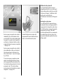
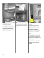
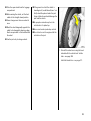
Electronic data acquisition in toll
sys tem s 3
O n vehicles with heat-reflecting
windscreens1 ) 3, m ount the c hipca rd 3 for
electronic data a cquisition and billing in
the black shaded zone of the windsc reen
on the left or the right behind the interior
rear-view m irror, see figure. If the chipc ard
is mounted outside this zone, malfunctions
ma y occur in data acquisition.
1)
52
Sola r Reflect.
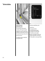
Mobile te lephones and radio
equipment (CB) 3
The Vauxhall installa tion instructions and
the operating guidelines p rov id ed by the
telephone manufa cturer m ust be observed
when fitting and operating a m ob ile
telephone. Failure to d o so could invalida te
the v ehicle’ s op erating permit
(EU Directive 95/54/EG).
Prerequisites for fault-free op eration:
z Professionally installed ex terior aerial to
ob ta in the max imum range possible,
z Maximum transmission power 10 Watt,
z Installation of the telephone in a suitab le
spot (see note on pag e 107).
Obtain ad vice on p redetermined
installation loc ations for the external
antenna and equipment holder and way s
of using dev ices w ith transmission power of
more than 10 Wa tts. We recom mend that
you consult a Vauxhall Authorised
Repairer, who will have brack ets and
various installation k its av ailable as
accessories and will install them in
accordance with regulations.
Be sure to use the handsfree attachment if
using the telephone w hilst driving. Ev en this
can be a distraction while driving. Please
ob serve country-spec ific regulations.
When used in the v ehicle interior, mobile
telephones and radio equipment (C B)
with integrated aerial may cause
malfunctions in the vehicle electronics.
Mobile telephones and radio equipm ent
(CB) should only be used with an aerial
fitted on the vehicle exterior.
53
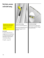
Keys, doors, bonnet
Re place ment ke ys
The key is a c onstituent of the electronic
immobiliser. Ordering keys from a Vauxhall
Authorised Repairer g uarantees problem free op eration of the electronic
immobiliser. Y ou will avoid unnecessary
costs, difficulties with insurance comp anies
when processing claims and problems
asserting wa rranty claims.
Keep the sp are k ey accessible in a safe
place.
Locks – see page 248.
Lock cylinders
Designed to free-wheel if they are
forcefully rotated without the correct k ey or
if the correct key is not fully inserted.
To reset, turn cy linder with the c orrect key
until its slot is vertica l, remove key and then
re-insert it. If the cylinder still free-wheels,
turn the key through 180° and rep eat
op eration.
54
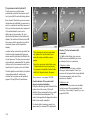
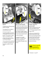
Child safety locks
Use the child safety lock whenever
child ren are occupying the rear seats.
Disregard may lea d to injuries or
endanger life. Vehicle p assengers should
be informed accordingly.
Using k ey, turn lever on rear door lock from
the vertical position: door cannot then be
opened from inside.
Ele ctronic imm obilise r
The sy stem checks whether the vehicle m ay
be sta rted using the key that has been
inserted. If the k ey is recognised as
"authorised" the vehicle can be started.
The c heck is carried out via a transponder
housed in the k ey – see page 56.
To act ivat e:
Switch off eng ine, turn key to position 0
and remove.
To deacti vate:
Turn key to position I I (ignition on); the
engine can then b e started.
Dea ctivation is not possib le in any other
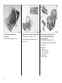
way , so keep spare key accessible in a safe
place!
Control i nd icator for imm obiliser
If control indicator o lights when the
ignition is switc hed on, the key is not
recognised by the system and the engine
cannot b e started:
1. Turn key to 0 in the ignition a nd remove.
2. Reinsert key in ignition switch.
3. Then repeat starting procedure.
If the control ind ic ator o remains lit, try to
start the engine using the spare key and
consult a workshop. We recommend a
Vauxhall Authorised Repairer.
If the control indicator flashes whilst the
ignition is on A , there is a fault in the
eng ine electronic s. The engine cannot be
started – see page 166.
Not e
The immobiliser does not lock the doors.
Therefore, after leaving the v ehicle a lways
lock it and switch on the anti-theft alarm
system 3 – see p ages 58, 63.
The Car Pass contains all of the vehicle’s
data and should therefore not be kept in
the vehicle.
Hav e y our Car Pass on hand when
consulting a Vauxhall Authorised Repairer.
55
Position m em ory on v ehic les w ith
electric ally operated front seats 3
When the vehicle is loc ked using the ra dio
freq uency remote c ontrol, the current
position of the driver’s seat and the exterior
and interior m irrors are stored. Personal
settings sa ved using va rious radio
freq uency remote controls can b e retrieved
as follows: open driver’s door within one
minute of unlocking and the positions
stored using the radio frequency remote
control are automa tic ally set – see
pag e 80.
C entra l lock ing system,
see page 58.
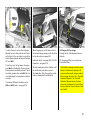
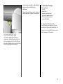
Radio fre quency re mote control
The rad io frequency remote control is
integrated in the key .
Used to op erate
z central locking system,
z mechanical anti-theft locking system 3,
z boot lid , tailgate,
z Vauxhall ala rm system 3 .
Electric windows can be opened and
closed 3 using the remote control unit. The
electric sun roof 3 c an be c losed using the
rem ote control unit.
The remote control has a range of approx.
3 metres. The range can b e affected b y
external influences. Point the remote
control at the v ehicle when opera ting.
56
For your conv enience, we recommend that
the central lock ing sy stem alway s be
op erated using the remote control unit.
Handle remote control with care, protect
from moisture and high temperatures and
avoid unnecessary operation.
Function check by brief illum ination of
ha zard warning flashers.
Mechanic al anti -theft locki ng system 3 ,
see page 58.
Boot l id or ta ilgat e,
see page 61.
Vauxhall ala rm system 3,
see page 63.
Electric w indows 3 ,
see page 120.
Electrica lly op era ted sun roof 3,
see page 123.
Fault
If the central locking system cannot be
opera ted with the remote control, it m ay b e
due to the following :
Mak e sure that you dispose of old batteries
in accordance with env ironmental
protec tion regulations.
After replacing batteries, synchronise
remote control: unlocking door using k ey
in lock – see next page. Insert key into
ignition.
z The range of the rem ote control has
been ex ceeded.
z Remote control b attery v oltag e too low,
cha nge batteries, see nex t colum n.
z Freq uent, rep eated opera tion of the
remote control outside the reception
ra nge of the vehicle (e.g. too far from
vehicle, rem ote control is then no longer
recognised). To synchronise remote
control, see nex t column.
z If the centra l loc king sy stem is
ov erloaded as a result of repeated
op eration at short interv als, the power
supply is c ut off for approx . 30 second s.
Changing the rem ote control ba ttery
Exchange the battery as soon as the range
of the rem ote control starts to become
reduced.
z Interference from higher-power radio
waves from other sources.
Insert a sma ll screwdriver in the notch in the
clip and lift. Pull the k ey part from the
remote control.
For c entral locking sy stem operation using
key – see following pa ges. Ha ve c ause of
fault remedied. We recommend that you
consult a Vauxhall Authorised Repairer.
The transponder for the imm ob iliser is in
the front of the k ey. Make sure that it is not
damaged or detached.
Open the remote c ontrol. Replace the
battery, ensuring that it is inserted correc tly
(see pa ge 275 regarding b attery ty pe).
Close the remote control, insert it in the k ey
part and ma ke sure it audibly engages.
57
Turn key in driver’s door loc k towards rear
of vehicle ag ain within 10 seconds after
locking, then turn it back to the vertica l
position a nd remove.
Lock buttons on all doors are positioned
such tha t doors ca nnot be opened.
Do not use the sy stem if there are people
in the vehicle! The doors cannot b e
unlocked from inside.
Central locking system
For doors, boot lid / tailgate and tank flap.
Locking
Press button p on rem ote control unit
– or –
Turn key in driver’ s door lock towards rear
of vehic le; then turn it b ack to the vertical
position and remove. Alternatively, when
locking from inside the vehicle, press the
central locking switch m in one of the front
doors 3 with the doors closed.
58
Securing wi th the mechanica l anti-t heft
locking system 3
All d oors must b e closed. The driver’ s door
must hav e been opened after the ig nition
was switched on. Within 10 seconds of
lock ing , press button p on the remote
control aga in
– or –
Not e
z If the driv er’s door is not closed properly ,
the central loc king sy stem will unlock
again immediately after lock ing.
z 30 seconds after unlocking using the
radio frequenc y remote control the doors
autom atically lock again if neither a
door nor the luggage compartment has
been opened.
z To loc k the d oors from within (e.g . to
prevent und esired a ccess from outside),
press the central lock ing sw itch m.
To unlock:
To unlock only the driv er’s door:
Press button q on remote control unit onc e
– or –
Turn key in driver’ s door lock once towards
front of v ehicle, then turn it back to the
vertic al position and remove.
Unlock entire vehic le
Press button q on rem ote control unit
twice
– or –
Turn key in driver’ s door lock towards front
of vehic le twice; then turn it bac k to the
vertic al position and remove. Alternatively ,
when unlocking from the inside, press
central locking switch m on one of the front
doors 3.
Central l oc king sw itch for loc king
and unlock ing the doors from insid e
the vehicle
Press button m on one of the front doors 3:
the doors are lock ed or unlocked as
appropriate.
z Locked doors unlock a utoma tica lly if an
accident of a certain sev erity occ urs (to
permit outside assistance) – prerequisite:
ignition must not be switched off.
When the mechanical anti-theft locking
sy stem is active – see pag e 58, the doors
cannot b e unlocked with this b utton.
59
O per ation of wi ndows and sun roof 3
O n vehicles w ith electronically operated
windows, the windows can be op ened a nd
closed from outside: Hold d ow n b utton q
or button p on the remote control unit, or
hold the k ey in the appropriate position in
the door lock, until all windows a re open or
fully closed.
The sun roof can be closed from outside:
Hold b utton p on the remote control
depressed or hold the key in the
appropriate position in the door lock until
the sun roof is fully closed .
Care must be taken when operating the
elec tric windows and the sun roof. There
is a risk of injury, especially for child ren,
and a danger that articles could become
trap ped.
Vehicle passengers should be informed
according ly .
Keep a close wa tch on the windows and
sun roof w hen closing them . Ensure that
nothing becomes trapped in them as
they m ov e.
Overloa d
If the centra l locking system is overloa ded
as a result of repeated operation at short
intervals, the p ow er supply is cut off for
approx. 30 seconds.
The system is protected b y a fuse in the
fusebox – see pag e 212.
For further inform ation on windows and
the sun roof – see pages 122, 124.
Malfunction in central locking sys te m
e.g. if vehicle battery is flat.
A = Unlock driv er’s door
Turn key forward in lock p ast
resistance p oint as far as it w ill go.
Turn key back to vertical position and
remove.
B = Lock driver’s door
With driver’ s d oor c losed , turn key
towards rea r of vehicle until it will not
mov e any further. Turn k ey back to
vertical position and remove.
The other doors can be opened and closed
by pulling or pushing the interior lock
button (not p ossible if a nti-theft ala rm
system enabled beforeha nd ). Have cause
of fault remedied. We rec om mend that y ou
consult a Vaux ha ll Authorised Repairer.
60
Luggage compartment
To unlock:
Press button r on remote control
– or –
Press button q on rem ote control twice
– or –
Turn key in driver’ s door lock forwa rd twice,
turn to vertical position and remove
– or –
Press button x in d riv er or passenger
side d oor 3.
The lug gage compartment is unlocked and
can be opened within 5 minutes. O n the
Saloon, this is d one b y pressing the button;
on the esta te car, by p ulling the button
under the handle.
If the luggage comp artm ent is open w hen
the ignition is on, s lights up in the
tachom eter displa y. A w arning b uz zer will
sound when the vehicle starts off.
There is a handle on the inside of the
luggage compa rtm ent lid or tailgate for
closing the luggage compa rtm ent.
If the lug gage c om partment is not opened
within 5 minutes, it is automatically locked
again.
If the luggage comp artm ent is unlock ed
the number plate lights come on and
illuminate the area behind the vehicle.
If the luggage comp artm ent has been
unlocked and opened, it is autom atically
lock ed again 5 minutes after closing.
The luggage compartment is
autom atic ally locked when the speed
reaches 2.5 mph (4 km /h).
61
Boot li d, Sal oon
The door central locking system ca nnot be
locked or unlock ed using the lugga ge
compartment lock.
Key slot in lock in horizontal position
The lugga ge com partment ca n be lock ed
and unlocked by op erating the remote
control or using the key in the driver’s sid e
lock.
Key slot in lock in v ertical position
The lugga ge com partment also rem ains
locked after unlocking using the remote
control or using the key in the driver’s sid e
lock. This position m ust be selected if the
luggage compartment is to remain lock ed
whenever this occurs.
62
Locking using k ey in luggage compa rtm ent
lock
Turn key c lock wise from vertical or
horizontal position as far a s it will go. To
guard against being lock ed out, the key
cannot then be removed.
After the luggage compartment has been
closed and the k ey turned back to the
horizontal or vertical position, the luggage
compa rtm ent is locked again.
O pen luggag e c om part ment
Do not drive with the luggage
compartment op en or ajar, e.g. when
tra nsporting bulky ob jects, since toxic
exhaust gas could penetrate the interior.
Fitting accessories to the boot lid or
tailgate will increase its weight. I f it
becomes too hea vy, the boot lid or ta ilg ate
will then not stay op en.
Vauxhall alarm s yste m 3
monitors:
z the doors, luggage compartment,
bonnet,
z the passenger c om partment,
z vehicle tilt, e. g. if it is raised,
z the ignition.
To activ ate:
All doors, windows a nd sun roof 3 must be
closed; press button p on the rem ote
control unit again within 10 seconds after
lock ing
– or –
Turn key in d riv er’s door lock toward s rear
of vehicle again within 10 sec onds after
lock ing , then turn it back to the v ertical
position and remove.
Sw itching system on excl ud ing
m oni toring of the pa ssenger
com partm ent and the v ehicl e t ilt
e.g. if anim als a re to be left in the vehic le.
1. Close tailgate and b onnet.
2. Press b utton Ä. The LED in the b utton
fla shes (max imum 10 seconds) – see
next p age.
3. Close doors.
4. Switch on anti-theft alarm system .
LED lights up. After app rox . 10 second s
the system is activated, without m onitoring of the passenger compartment or
vehicle tilt. LED flashes until sy stem is
switched off.
6
63
After the first 10 seconds of anti-theft
alarm system activation:
z LED flashes
= System on
z LED lights up for
approx . 1 second = Switch-off
If a system fa ult occ urs, consult a
work shop. We recom mend a Va ux ha ll
Authorised Repairer.
Light emit ting d iode (LED)
During the first 10 seconds of anti-theft
alarm system activation:
z LED lights up
=
Test, switch-on
delay
z LED flashes
=
Door, tailgate,
bonnet open
or system fault
64
To deact ivat e:
Press button q on remote control
– or –
Turn k ey in driver’s door lock towards front
of vehicle, then turn it back to the vertica l
position a nd remove.
Ala rm
O nly a certain num ber of a la rm s are
allowed to be trigg ered while the anti-theft
alarm system is switched on (this number is
stipula ted b y law).
The alarm takes the form of:
z an acoustic signal (horn) a nd
z a visual sig nal (haz ard warning lights).
The duration of the a larm signals is limited
due to lega l regulations.
Alarm c an be cancelled by pressing a
button on the remote control. The antitheft wa rning system is switched off at the
same time by p ressing the button q .
O peni ng and cl osing boot lid or tail gate
using remote contr ol unit butt on r wit h
anti -theft alarm system enabled
1. Press button r on remote c ontrol,
lugga ge c om partment is unlocked –
see pa ge 61, and passenger
com partment and v ehicle tilt is disabled.
2. Opening lugg age com partment –
see pa ge 61.
3. After closing the luggage compartment
the monitoring of the passenger
com partment a nd vehicle tilt is enabled
again after ap prox . 10 seconds.
Opening a nd closing the lugg age
compa rtment wit h the key in the luggag e
compa rtment lock 3 w ith anti-theft alarm
system enabled
1. Turn key clockwise as fa r as it will go:
the lugg age com partment is unlocked
and m onitoring of the pa ssenger
compa rtm ent and v ehicle tilt is
deactivated.
2. O pening luggage compa rtm ent –
see page 61.
3. C lose lug gage compartment.
4. Turn k ey ba ck to previous position: After
approx . 10 second s, monitoring of the
passenger compartment, lug gage
compa rtm ent and vehicle tilt is resumed.
Alarm siren
with integrated battery 3
The alarm siren monitors the on-board
voltage network and triggers an ala rm if
this network is manipulated (e.g . if the
vehicle’s ba ttery is disconnected by
unauthorised persons). The alarm siren ha s
its own power supply and is therefore not
dependent on the vehicles battery .
If the vehicle’s battery is to be
disconnected (e.g. for maintenance w ork ),
the alarm siren must be dea ctivated as
follows: sw itch the ignition on then off,
disconnect the vehicle’s battery within 15
seconds.
To swit ch off alarm siren:
S witc h ignition on then off.
65
Consult a Vauxhall Authorised Repairer for
details on compatible systems.
Ensure that no persons, animals or
objec ts are in the m ov ement zone of the
system to be operated (e.g. a ga ra ge
door). Vehicle passeng ers should be
inform ed of the hazards.
Basic program ming of t he univ er sa l
rad io control syst em
1. Switch on ignition.
2. When programming for the first time,
press both outer buttons under the
mirror housing, until the control indicator
along side the b uttons fla shes rapidly .
3. Hold the ma nual remote control unit at a
distance of 0 to 30 c m from the control
button area of the mirror housing.
4. Press the button on the manual rem ote
control unit while p ressing and holding
the desired button of the univ ersal radio
frequency remote control.
Universal radio frequency remote
control in mirror housing 3
To opera te up to 3 different remotely
opera ted systems (e.g. garage door,
domestic alarm system, domestic exterior
lighting ).
The p rogram med univ ersal radio
frequenc y rem ote control can rep lace the
individual remote control units of the
systems to be operated. Three buttons on
the underside of the m irror housing can be
used to operate v arious systems.
66
5. The control ind ic ator in the mirror
housing will flash slowly at first. As soon
as it flashes rap id ly, release both
buttons. The universal radio control
sy stem is now programmed for the
chosen system.
6. To programme other buttons w ith other
sy stems, repeat steps 3 to 5.
If a sy stem does not operate the device
desp ite repeated programm ing and the
control ind icator briefly flashes rapidly
and then shines with a steady g low for
2 seconds, the receiver m ay be fitted with
a variable code system – see next page.
Program ming t he univ er sa l radio control
system for varia ble code systems
1. Perform basic programming –
see previous page.
2. Activ ate synchronisation mode of
system (see sy stem manufacturer’s
system operating m anual) and briefly
press the pre-p rogram med button on
the univ ersal radio freq uency remote
control three times w ithin 30 second s.
3. The radio control sy stem is now
prog ra mmed for variable code system s.
To prog ra mme other systems for
variable codes, repeat the above
procedure for the other buttons of the
universal ra dio control system .
Using the univ ersal radio cont rol system
With the ignition on, press the required
universal radio control button, and the
control indica tor in the mirror housing will
illuminate. The pre-p rogram med sy stem
can now be operated using the universal
radio control sy stem.
Rep rogram ming ind ivid ua l butt on
sett ings
If a button that has already been
prog ra mmed is to be used for a different
sy stem, simply repeat steps 3 to 5 of the
basic programming procedure described
previously .
Erasing all prog ramm ed button settings
Before selling the vehic le, it is a good idea
to erase b utton settings.
Button settings can only be era sed as a
unit. I t is not p ossible to erase individual
button settings. Buttons can, how ever, be
indiv idua lly rep rogram med
(see " Reprogramm ing ind iv idual button
settings").
In order to erase the programming of all
3 buttons, press both outer buttons and
relea se as soon as the LED begins to flash
(a fter approx. 20 seconds). All button
settings hav e now been cleared and can be
prog ra mmed anew at any tim e.
Not e
Retain the ma nual remote control in case
reprog ra mming is required. It is also
possible to continue using the manual
remote control.
If a fter repeated ly performing the above
steps a system fails to respond to the
universal rad io control, consult a workshop.
We recommend that you consult a
Vauxhall Authorised Repairer.
During programm ing, the vehicle should be
within the range of the receiv er. Under no
circumstances should the vehicle be in the
mov ement zone of a system (e. g. garag e
door).
Do not programm e systems which do not
have an automatic safety stop
(manufactured b efore 1982).
Take note of the sy stem ma nufacturer’s
safety instructions for drives a nd manual
remote control units.
67
The b onnet is held open automatically. To
close the bonnet, lower it slow ly and allow
it to fall into the lock und er its own weight.
C heck that the b onnet is locked in position
by pulling at its front edge. If it is not
eng aged, repeat the procedure.
Bonnet
To open the bonnet, p ull the outer release
lev er / located below the instrument
panel on the driver’s side. The bonnet will
then be unlocked and will partially open.
Return the relea se lev er to its origina l
position.
68
There is a safety catch on the underside of
the bonnet: lift this upwards and open the
bonnet.
When the bonnet is opened, snow or d irt on
the bonnet can slide down and obstruct the
air inta ke. Air intak e – see page 142.
Seats, Interior
Adjusting the front s eats
see p age 5.
Electrically adjustable front seats 3
see p age 79.
Increasing luggage compartment
size by folding down the front seats
see p age 82.
Seat pos ition
Adjust driver’s sea t such that with the
driver sitting upright the steering wheel is
held in the area of its upper spokes with the
driver’s arms slig htly bent.
Push p assenger seat as far b ack as
possible.
The seat back rests m ust not be tilted too
far ba ck (recom mended tilting angle
app rox . 25° ).
Imp ortant: Do not sit nearer than 10
inches (25cm) from the steering w heel, to
permit safe airbag d eploym ent.
Disregard can lead to injuries which
could be fa tal. Vehicle passengers
should be informed ac cord ingly .
69
Head restraint position
He ad res traints
The midd le of the head restraint should be
at eye lev el. I f this is not possible for
extremely tall persons, set to highest
position, and set to lowest position for
small persons.
To rem ov e head restraints: Release the two
springs by pressing them and d etach the
head restraint.
Disreg ard can lead to injuries which
could be fatal. Vehicle p assengers
should be informed accordingly.
Setting – see page 7 and right hand column.
70
Rear head restraints, integrated in
the re ar se at backres t 3
Setting – see page 7.
To adjust them, pull the head restraint
forwards with both hands and at the same
time adjust the height.
To enlarge the luggage compa rtm ent,
push the hea d restra int all the w ay down –
see p age 7.
The head restraints can be moved to the
lowest position to improve visib ility where
seats are unocc upied.
Armrest 3 between the front s eats
The arm rest can be pushed forw ard. If the
armrest is not req uired, push it back and
fold it up.
To op en, slide the armrest back, press the
button on the front and open.
Rear seat armrest
The armrest can be folded down.
If the rear centre seat is being used or the
rear sea t ba ckrests are b eing folded down,
fold armrest up ward.
To open, p ress the button on the front and
open.
The maximum permitted load on the
stowage compartment is 0.5 kg .
71
Travel As sistant 3
Instal ling the Trav el Assista nt
Insert the tw o rear push-in sleeves into the
marked recesses in the ba ckrest and
enga ge.
72
Swivel open a nd hold cover of front
attachment points in floor in front of
console.
S wivel c onnecting console d ownw ard and
eng age in attachment points.
Swiv el the locking lev er downwards.
Check the locking p osition of the Travel
Assistant: the red mark (see Fig. 15028 J)
must not be visible. Otherw ise, lock using
the key – see page 77, Fig. 15037 J .
To lock, insert Tra vel Assistant into recesses
in connecting console and slid e back as fa r
as possible.
If it is correctly locked, the red m ark must
no longer b e v isible in the window,
otherwise the procedure must be repeated .
If it is not correctly locked, the Travel
Assistant could b e propelled forward
with considera ble force when hard
braking occurs, risk of injury.
6
73
The up per stowage compartment is
located under the armrest. To open, press
the button and fold the armrest upwa rds.
Drink hol der and ac cessory soc kets
O pen the drink hold er by pressing the
marking.
O nly accessories with max imum power
consump tion of 120 Watts must be
connected to the a ccessory sock ets. For
notes – see pa ge 89.
74
Stowa ge compa rtments
Open the lower stowag e com partment by
pressing the mark ing. The underside of the
compartment has an opening through
whic h the objects in the compartment can
be ra ised.
Connecting consol e for DVD pl ayer 3
Pull connecting console upward, p ress
button and slid e downward .
Swivel up the display holder, slide DVD
player display into brack et from below a nd
fix in position with brack et.
Electric c ool box
To open, fold open the armrest together
with the stowage compa rtm ent.
Maximum loa d: 1 kg.
75
Switch on the cool box as needed.
Ta bles
Fold arm rest upward (1).
Use recessed grip to p ull tab le upward as
fa r a s it will go (1), sw iv el table forw ard (2)
and fold downward (3).
76
S et required clearance b y adjusting
longitudinal position of table (4).
To fold away the tab le, swivel the
armrest up.
Push the table forw ard as far as it will go (1).
Fold the table upwards p ast the resistance
point (2), swiv el it downwards and insert in
the Travel Assista nt (3).
Swivel armrest down.
Remov ing the Trav el Assistant
O pen catch using key , red mark appears in
window.
6
77
Pull the Tra vel Assistant to the front on the
connecting console and remove.
Fit the protec tiv e cov er 3 on the plug.
78
Press the locking lev er down, press the
button on the front of the connecting
console a nd sw iv el the locking lev er
up wards.
S wivel connecting c onsole upward and pull
out of recesses.
Adjusting the long itudinal p osition
Move switch 1 forwa rd s / ba ckwards.
Ele ctrically adjustable front se ats 3
Care must be taken when operating the
elec trically adjustab le sea ts. There is a
risk of injury, p articularly for children,
and a danger that articles could become
trap ped.
Height adjustm ent
Move switch 1 upw ards / downwards at
rear.
S eat ba ck adjustment
Turn sw itch 2 forwards / backw ards.
Keep a close watch on the seats when
adjusting them.
O perate switch until desired seat position is
reached. Seat position – see p age 69.
Vehicle passengers should be informed
according ly .
After a djusting the seat, adjust height of
seat belt – see page 98.
Adjustment
The seat p osition can be adjusted by
means of switches on the outboard side of
the seats.
Ad justing the inclination
Move switch 1 upwards / downwards at
front.
79
Elec trical ly operat ed lumba r sup port 3
on driv er’s seat
Adjust lumb ar support using four-way
switch on outboard side of driver’s seat.
Adjust lumb ar support to suit personal
req uirements.
Moving support up and d ow n: push b utton
up or down.
Increa sing and decreasing support: push
button forward or backwa rd.
80
Thi gh sup port 3 on driver’s seat
To adjust, lift handle at front and slide sea t
padding.
Do not a djust the thigh support whilst
driving.
Memory function 3 for elec trical ly
ad justable dri ver’s sea t, exterior mirrors
and interior mi rror
Three different seat and mirror settings can
be stored (e.g. for three drivers).
Readiness for operation
Storing settings
z With ignition on,
1. Adjust seat,
z Within 10 m inutes of switching ignition
off,
2. Adjust interior mirror – see page 8,
z Within 10 m inutes of opening or closing
the driver’s door,
z Within 10 m inutes of inserting or
removing the ignition k ey.
Readiness for operation stops when the
vehic le is locked.
3. Adjust exterior mirror – see page 8,
4. Press m emory button M and the position
button to be used (1, 2 or 3)
simulta neously, and stora ge is
ack nowledged by an acoustic signal.
Retriev ing settings
Keep position key 1, 2 or 3 pressed until the
stored sea t and mirror positions have b een
reached .
For reasons of safety, seat adjustm ent
stops immediately if the p osition button is
relea sed or one of the setting buttons is
op erated.
Ad justments may only be performed with
vehicle stationary.
S tore and activ ate the setting s using the
remote controls
When the vehicle is loc ked with the radio
freq uency remote c ontrol, the current
positions of the d riv er’s seat, the exterior
mirrors and the interior m irror a re stored.
Personal settings stored using different
radio frequency remote controls can be
retrieved as follows: op en driver’s door
within one m inute of unlocking a nd the
positions stored using the radio frequency
remote control are autom atically set.
The seat adjusting proc edure can be
stopped immediately if required by
operating a setting button.
Passeng er m irror w ith par king a id
see page 8.
O verload
If the seat setting is electrically overloaded,
the power supply is automatically cut off
for a short time.
The sy stem is protected by a fuse in the
fusebox – see page 212.
81
Luggage compartment extens ion
Fold dow n the cover behind the arm rest
Fold down the a rm rest on to the seat
cushion, pull the handle and tilt the cover
forwards.
The outer seats can continue to be used for
passengers.
Enga ge the cover behind the centre
armrest a udib ly in position.
Cover behind arm rest can be locked from
lugg age compartment 3: turn handle 90°:
Folding d own the rear seat ba ckrests
Push the rear head restraints right down.
Locked
=
Unlock ed =
Place the b elt buckles in storage pockets in
the seat cushions.
Handle horiz ontal
Handle vertic al
Push front seats forwards a little.
Remove Travel Assistant 3 – see page 77.
Unlock one or both rear sea t backrests by
depressing p ushbuttons and fold down on
to seat cushion.
Return the air front seats to the desired
positions.
82
Luggage compartment cover 3,
5-door Saloon (Hatch)
When returning rear seat back rests to
upright, they should audibly click into
position.
Fold ing down t he front passenger seat 3
Push head restra int on front passenger’s
seat down as far as it will g o.
The three-point seat belt for the centre rear
seat can only be pulled out of the retractor
if the rear seat backrests are prop erly
locked into position.
Slide back the front p assenger seat.
To remove, unhook the retaining straps
from the tailgate.
Fold front passenger sea t forwa rd by
ra ising release lever.
Fit in reverse order.
O n some versions, the rear seat b ackrests
can be locked 3 : insert the key in the lock
nex t to the pushbutton, turn 180° a nd
rem ov e – see figure.
Remove the cover from the side guides.
When returning front passenger seat
backrest to upright, it should audibly c lic k
into position.
Notes on loading
see p age 88.
83
Luggage compartment cover 3,
Estate
Rem oving
Open luggage compartment cover.
Safety net 3,
Estate
To close:
Pull lug gage compartment cover toward s
rea r of vehicle using handle and hook into
side retainers.
Move release lev er on right side of lug gage
compartment cov er upwa rd . Lift rig ht
cover a nd remove from brac kets.
The safety net can be fitted behind the rear
seats or, with the rear seat back rest folded
down, behind the front seats.
Fit ting
Fit the lug gage compartment cover in the
bracket on the left-hand side, fold up the
relea se lever on the right-ha nd side, fit the
lugg age compartment cover in the bracket
on the right-hand side and p ress the
relea se lev er closed.
Fitti ng behind the rear seats
Remove the luggage comp artm ent cover.
Do not place any heavy or sharp-edged
objects on the cover.
To open:
Remove luggag e compartment c ov er from
side b ra ckets. I t rolls up automatically .
84
Fit the ca ssette with rolled safety net into
the side brack ets and enga ge b y twisting .
Ex tend the net from the cassette. The roof
frame houses two fitting openings. Fit the
net rod in the fitting opening on one side
and then the other and engage by pushing
forward.
Fit the luggage compa rtm ent cover.
Removing
Remove the lug gage compartment cover.
Detach the safety net rod from the
brackets in the roof frame.
Slide both latches inwards; push the
cassette with rolled net rea rw ards in the
bracket, twist and rem ov e upw ards.
Fitti ng behind front seats
Fold both rear seat back rests. Place the
rolled net on the floor behind the front
seats in suc h a way that the cog rail in the
slit on the net is to the rear.
Pull ea ch side hook from the cassette and
attach it to an eye 3 in the vehicle floor.
Extend the net from the cassette. The roof
frame houses two fitting openings. Fit the
net rod in the fitting opening on one side
and then the other and engag e by pushing
forward.
Removing
Detach the safety net rod from the
brack ets in the roof frame.
Undo the side hooks from the eyes 3 in the
vehicle floor.
85
Lashing eyes
FlexO rganizer 3
These enable loads to be secured in
position in the lugga ge compartment using
lashing straps 3 or a luggage net 3 .
Flexible sy stem for dividing the luggage
compartment or securing load s in an
Estate.
The components are housed in a stow age
compartment at the rea r in the load floor –
see p age 92.
The system c onsists of
z variab le partition net
z variab le partition wall
z partition rod
z mesh p oc kets for the side walls
z hooks
The components can be mounted in the
two guide ra ils in the side walls of the
lugg age compartment.
86
The figures show examples of possible
uses.
Varia ble part ition wa ll
Fig. 15179 J . Press the rod s of the partition
wall together slightly and engage in the
desired guide rail openings in the side
walls. The rods c an be engaged in various
positions.
Varia ble part ition net
Fig. 15180 J . Press the rod s of the partition
net tog ether slightly and engage in the
desired guide rail openings in the side
walls. The rods c an be engaged in various
positions. The partition net can be
mounted vertically or horizontally at
different levels.
Hooks and mesh poc kets for the sid e wa lls
Fig. 15181 J. Engage the hooks in the
openings of the guide rails in the sid e walls
as indic ated in the figure and turn 90°. The
mesh pockets can be hung from the hooks.
Rem oving
Press together the rods of the partition
wall / net or the telescopic rods and remove
from the guide rails. Turn the hook s 90°
and rem ov e.
FlexOrga nizer stowa ge
FlexOrga nizer c om ponents are housed in a
stowage compa rtm ent at the rear in the
loa d floor. To open, ra ise the handle and
op en the flap – see pag e 92, Fig. 15171 J.
To stow, pull apa rt the partition wall / net
rods as well as the sepa rate telescopic rod
in the middle and fold them in half. Roll the
partition wa ll and net together and place it
in the compartment with the other
components. C lose the c ov er.
87
z Do not place any objec ts in front of the
rear window or on the instrum ent panel.
They a re reflected in the glass, obstruct
the driver’s view and will be thrown
through the vehicle, for instance in the
event of heavy braking.
Notes on loading the vehicle
z Heav y objec ts in the lug gage
com partment should be placed as far
forward as possible aga inst the engag ed
rear seat backrests or, if the rear seat
backrests are folded down, against the
front seat b ackrests. If objects a re to be
stacked, the heav ier objects should be
placed at the b ottom. Unsecured objec ts
in the luggage compartment would be
thrown forward with great force in the
event of heavy braking, for exam ple.
z Secure heav y objec ts with lashing
straps 3 atta ched to lashing ey es –
see page 86. If heavy loads slip when the
vehicle is braked heavily or driven
around a bend, the handling of the
vehicle may chang e.
z Saloon: loose objects in the lugg age
com partment should be secured ag ainst
slipping using a luggage net 3 –
see pa ge 86.
z Estate: when transporting objects in the
lugga ge compa rtm ent, fit a safety net 3
– see page 84, or FlexO rganizer 3 –
see pa ge 86.
z Estate: close the luggage compa rtm ent
cov er so there is no reflection in the rea r
wind ow.
88
z Objects m ust not be stored in the a irb ag
inflation area, because they could cause
injury if the airbag inflates.
z Do not drive with the luggage
compartment op en, e.g. when
tra nsporting bulky ob jects, since toxic
ex haust gas could p enetrate the interior.
z If objects are being transp orted in the
luggage compa rtm ent, the rear sea t
back rests m ust be locked in position –
see page 82.
z Do not a llow the load to protrude ab ov e
the upp er edge of the rear seat
back rests, or above the upper ed ge of
the front seat b ackrests if the rear seat
back rests a re folded down.
z The warning triangle 3 and first-aid kit 3
must alway s b e freely a ccessib le.
z Weights, payload and roof loa d –
see page 262.
z Driv ing with a roof load – see p ages 158,
161, 188, increases the sensitivity of the
vehicle to cross-winds and has a
detrimenta l effec t on vehicle handling
owing to the vehicle’s higher centre of
gravity.
Disregarding the instructions can
potentially lead to fatal injury. Vehicle
passeng ers should be inform ed
accordingly.
Cigarette lighte r ) 3
Accessory socket 3
In front centre console.
The soc ket in the centre console and the
cigarette lighter socket can be used to
connect electrical accessories. The sockets
are ready for operation when the ignition is
switched on. If the eng ine is not running the
battery will be discharged. An a dditional
accessory soc ket 3 can be found in the
centre console b eneath the rear air vents
and in the Travel Assistant 3.
Press in cigarette lighter with ignition
switched on. S witches off autom atically
once the element is glowing. Pull out
lighter.
Estates have an additional accessory
socket to the left in the luggag e
compartment next to the lug gage
compartment lig hting.
Do not dam age the soc kets by using
unsuitable plugs.
The maximum power c onsumption of
electrical ac cessories m ust not ex ceed
120 w atts.
Do not connect any current-delivering
acc essories, e.g. electrical charging
devices or b atteries.
Electrical ac cessories connected to the
socket must c om ply with the electroma gnetic compa tib ility requirem ents laid
down in DIN VDE 40 839, otherwise vehicle
ma lfunctions m ay occur.
Accessory sockets in the Trav el Assistant 3 –
see page 74.
89
Ashtray
To be used only for ash and not for
combustible rubbish.
Disreg ard c an lead to injuries which may
be fatal. Vehicle pa ssengers should be
informed accordingly.
Ashtray, front
The cover opens when pressed at the point
indicated .
90
To empty , grip b oth sides of the ashtray
insert a nd pull upwards.
Rear a sht ray 3
In the rear c entre console.
The cover op ens when pressed a t the point
indicated.
To empty: open the ashtray, press the
spring (arrow ) and pull out the ashtray.
Glove com partm ent
To open, pull hand le upwards.
At the front of the opened cover there is
a p en holder.
Cooled glove compartment 3 –
see page 139.
Stow age compartment in the roof
lining 3
Stowage compartments in the
luggage compartme nt
To op en, press the point indic ated.
To acc ess p ress d ow n bar and open the
cover.
The max imum permitted load on the
stowage compa rtm ent is 0. 4 kg.
The stowage compartment m ust be closed
whilst driving.
Warning triangle ¨ 3 and first-aid kit + 3
stowage – see page 204.
S towing the spare w heel – see page 205.
J ack and vehicle tools stowage –
see page 208.
6
91
Estates hav e an a dditional stowage
compartment in the luggage com partment
floor.
To open, pull the release lever and open
the flap.
92
When op ening, ensure that the flap opens
at the seam so that the entire floor cover is
not raised .
Drink holders , front 3
The drink hold ers can be found between
the front seats in the centre c onsole: slide
cover open.
Sun visors
Use the sun visor to protect from glare by
pulling it down and swivelling it to the side.
Drinks holders , rear 3
The d rinks holder can be found b eneath
the centre seat: pressing front ed ge mov es
drink holder out.
93
Safety systems
Three-stage re straint system
Comprising:
z three-point seat belts,
z belt tensioners at the front seats and the
rea r outer seats,
z airbag sy stems for driver, front
passenger and outer rea r seats 3.
The three stag es are a ctivated in sequence
depending on the seriousness of the
accident:
z The automa tic seat belt locking devices
prevent the belt strap from being pulled
out and thus ensure that the v ehicle
occupants are retained in their seats.
z The front seat b elt buckles and outer
rea r seats are pulled downwards. As a
result, the seat belts are instanta neously
tightened and the occupants are mad e
aware of the deceleration of the v ehicle
at a very ea rly sta ge. This reduc es the
stress p laced on the body.
z The airbag sy stems a re also triggered in
the ev ent of serious accidents and form a
safety cushion for the occupants.
Depending on the severity of the
accident, the front a irb ags inflate in two
stages.
94
The airbag systems serve to supp lement
the three-point seat belts and belt
tensioners. The seat belts must therefore
always be worn. Disregard of these
instructions may lea d to injuries or
endanger life. Vehicle p assengers should
be informed accordingly.
Be sure to rea d the a ccompanying
desc ription of the child restraint system !
Seat belts
Alwa ys wea r your seat belt, and that
means also in urb an traffic and when
you are a rear seat passenger. It can
save y our life!
Pregnant women m ust alwa ys wear a
seat belt – see page 98.
In the event of an accident, persons not
wearing sea t belts enda ng er their fellow
oc cup ants and themselves.
Warning light X for the seat belt – see
page 35.
Sea t belts are desig ned to be used by only
one person at a time. They are not suitable
for a ny one under 12 years of age or
150 cm.
For children up to 12 years of age we
recommend the Vaux hall child restraint
system – see page 110.
Three-point seat belts
The vehicle is equipped with three-point
seat belts with automatic retrac tors and
locking d evices, allowing freedom of body
mov ement although the spring-tensioned
belts always ensure a snug fit. For seat
position – see pages 69, 99.
The belt has a " vehicle sensitive retra ctor"
which is designed to lock during hea vy
acc eleration or deceleration in any
direction.
95
Belt tens ioners
The front seat belt and outer rear seat
systems are equipped with b elt tensioners.
If a head-on or tail-end collision of a
certa in severity occurs, the belt buckles are
pulled downward and the shoulder and lap
belts are tightened in an instant.
Actuati on of belt tensioners
is indicated by illum ina tion of control
indica tor v, see next p age.
The belt tensioners must be replaced after
activation. We recommend that you
consult a Vauxhall Authorised Repairer.
If the seat belts are unda maged the
op eration thereof is unaffected, even if the
belt tensioners have been triggered.
Further inform ation – see page 99.
96
C ont rol indic ator v for belt tensioners
The belt tensioners are monitored
electronically together with the a irb ag
systems and their operational rea diness is
indicated on the instrument panel by
control ind icator v. When the ignition is
switched on, the c ontrol indicator lights up
for approx. 4 seconds. If it does not light
up, does not go off after 4 seconds, or
lights up while d riv ing, there is fault in the
belt tensioner sy stem or the a irb ag system s
– see page 105. The belt tensioners or
airbag sy stems may fail to trigger in the
event of an a ccident.
Have the cause of the fault remedied .
We recom mend that y ou consult a
Vauxhall Authorised Rep airer.
The system ’s integrated self-diagnostics
allows faults to be quickly remedied. have
Ca r Pass on hand when consulting a
Vauxhall Authorised Repairer.
The c ontrol indicators can also be located
in the tac hometer d isplay dial – see
page 37.
Imp or tant
z Accessories and other objects must not
be affixed or placed within the action
zone of the belt tensioners a s this may
result in injury if the belt tensioners are
triggered.
z Do not mak e any modifications to the
components of the belt tensioners, as
this will render the vehicle unroadworthy.
Imp roper handling (e. g. removal or
installation) can activ ate the belt
tensioners – risk of injury .
z The belt tensioner and airbag sy stem
control electronics can be found in the
centre console area. In order to av oid
malfunctions, do not store mag netic
objects in this a rea.
z We recom mend that you have the front
seats removed by a Vauxhall Authorised
Repairer.
z The belt tensioners only actuate once.
Please replace belt tensioners that have
been triggered. We recom mend tha t you
consult a Vauxhall Authorised Repairer.
z Applicable safety directives must always
be ob served when disposing of the
vehicle. For this reason, d isposal should
be performed by an authorised recycling
company. We recommend that you
consult a Vauxhall Authorised Repairer.
97
Using the belts
Fitting seat bel ts
Pull the belt out of the retractor and guide
it across the body , making certain that it is
not twisted.
Insert the la tch plate into the buckle. The
front sea t b ackrest must not be tilted back
too far or the seat belt will not op erate
properly . The recommended angle of
inclina tion is 25° . Mak e sure that the lap
belt is not twisted and that it fits snugly
across the body. Tension the belt
frequently while d riv ing by tugging the
diagonal pa rt of the belt.
98
O n pregnant women in particular, the
lap belt must be positioned as low as
possible ac ross the pelv is so as not to put
too much pressure on the abdomen.
Bulk y clothing prevents the belt from fitting
prop erly. The belt must not rest against
ha rd or fragile objects in the pockets of
your clothing (e.g. ballpoint pens, keys,
spectacles) because these could cause
injury. Do not place any objec ts (e.g.
ha ndb ags, mobile phones) b etween the
belt and your body.
Height adjustm ent
of seat belt upper anchora ge p oint:
1. Pull b elt out slig htly.
2. Front seat b elts: Press button down or
slide belt guide up.
Rear seat belts: Press belt guide and
slide it upwards or downwards.
3. Set desired height.
4. Allow anchorage to lock aud ibly into
position.
Do not adjust height while driving .
Testing the belts
Plea se check all parts of the b elt system
occasionally for dama ge a nd correct
operation. H ave da maged parts replaced .
In ca se of an accident, please replace
overstretc hed belts and triggered belt
tensioners. We recommend consulting a
Vauxhall Authorised Repairer.
Do not perform any altera tions on the
belts, their anchorages, the automatic
retrac tors or the belt buck les.
Mak e sure that b elts are not da maged or
trapped by sharp-edged objec ts.
Adjust height such that the belt p asses
over the wearer’s shoulder and rests
against the shoulder. It must not pass over
the neck or upper arm.
Rem oving t he b el t
To remove the belt, d epress the red
pushbutton on the buckle; the b elt will
retract automatically.
Three-point seat b el t on centre rear sea t
The belt can only be pulled out of the
retractor if the ba ck seat rests are engaged
in their retainers – see page 82.
99
Exception:
Passenger sea t with seat occupancy
recognition system 3 . The seat occupancy
recognition system deactiva tes the
passenger front and side airbags if the
passenger seat is unoccupied or a
Vauxhall child restraint system with
transponders 3 has been fitted to the
passenger seat. S eat occupa ncy
recognition – see page 105. Vauxhall child
restraint system w ith transponders 3 –
see page 110.
Examples of events triggering the front
airbag sy stem:
Vauxhall Full-Size airbag s yste m
The front airb ag system will be trigg ered :
Front airb ag
The front airbag system is identified by the
word AI RBAG on the steering wheel and
above the glov e c om partment.
z depending on the severity of the
accident,
The front airbag system comprises:
z an airbag with inflator in the steering
wheel and a second one in the
instrum ent panel,
z the control elec tronics with impact
sensor,
z the a irb ag system s control indicator v in
the instrument panel,
z seat occupancy recognition 3 ,
z the control indica tor for Vauxhall child
restraint sy stems y with transponders 3
in the instrument panel.
100
z depending on the type of impact,
z within the range shown in the figure,
z indep endent of side airbag a nd curta in
airbag sy stem 3.
z Impact against a non-y ielding obstacle:
the front airbags are trigg ered at low
vehicle speed.
z Impact against a yield ing obstacle
(such as another vehicle): the front
airbags are only triggered at a hig her
vehicle speed.
When trigg ered , the front airbags inflate in
milliseconds to form a safety cushion for
the d riv er and front passenger. The
forward movement of the front seat
occupants is c hecked, thereby
sub stantially reducing the risk of injury to
the upp er body and hea d.
No im pairment of view will occur, because
the a irb ags inflate and deflate so quickly .
The front airbag sy stem provides
optimum p rotection when the seat,
back rest and head restra int are correctly
adjusted: Adjust the driver’s seat
according to the occupant’s height such
that with the driver sitting upright the
steering wheel is held in the a rea of its
upper sp ok es with the d riv er’s arms
slightly bent. The front passenger’ s sea t
should b e as far b ack as possible, w ith
the back rest upright – see pa ges 5, 6, 69.
Do not place the head, b od y, hands or
feet on the covers of the airbag sy stems.
The front airbag sy stem will not be
triggered in the ev ent of:
z the ignition being switched off,
z minor frontal collisions,
z accidents in which the vehicle overturns,
z collisions involving a sid e or rear impac t,
that is to say, if it w ould not be of benefit to
the oc cup ants.
Do not place any objects in the area in
which the airb ags inflate. Im portant
inform ation – see page 107.
The three-point seat belt must be
correctly fitted – see page 98.
101
Seat belts must therefore always be
worn. The front airbag system serves to
supplement the three-point seat belts.
If you d o not wear your seat belt you risk
being seriously injured, or even thrown
from the vehic le, in the ev ent of an
accident.
In the event of an accident the belt helps
to keep you in the correct seating
position, so that the front airb ag system
can provide you with effective
protection.
In addition, the front airb ag sy stem will not
be triggered for the front passenger in
versions with seat occupancy recognition 3
if:
z the front passenger’s seat is unoccupied,
z there is a prop erly fitted Va ux ha ll child
restraint system with transponders 3 .
Seat oc cup ancy recognition – see
page 105. Vauxhall child restraint
system with transponders 3 –
see pa ge 110.
Side airb ag 3
The side a irb ag system is identified by the
word AIRBAG on the outb oa rd sides of the
front seat backrests.
The side airbag sy stem will be triggered:
The side a irb ag system c om prises:
z within the range shown in the figure on
the centre door pillar of the driver’s or
front passenger side,
z an airbag with infla tor in the back of the
driver’s and front passenger’s seat
respectively ,
z the control electronics,
z the side impact sensors,
z the airbag systems control ind icator v in
the instrum ent panel,
z seat occ upa ncy rec og nition 3,
z the control indicator for Va ux ha ll child
restraint systems y with transponders 3
in the instrum ent panel.
102
z depending on severity of the a ccident,
z depending on the ty pe of im pact,
z ind epend ently of the front airbag
sy stem.
Exception:
Passenger sea t with seat occupancy
recognition system 3. S eat occupancy
recognition system deactiva tes the
passenger front and side airbags if the
passenger seat is unoccupied or a
Vauxhall child restraint system with
transponders 3 has been fitted to the
passenger seat. S eat occupa ncy
recognition – see page 105. Vauxhall child
restraint sy stem with transponders 3 – see
pag e 110.
There must be no objects in the area in
which the airb ag inflates or in the a rea
between the seat backs and the vehicle
body . Do not place the hands or arms on
the covers of the airba g systems.
Imp ortant information – see page 107.
The three-p oint seat b elt m ust always b e
correctly fitted – see page 98.
The side airba gs will not be triggered in the
event of
z the ig nition being sw itched off,
z fronta l collisions,
When the side a irb ag is triggered it inflates
within milliseconds and provides a safety
barrier for the driver and/or pa ssenger in
the v icinity of the relevant front door. This
red uces the risk of injury to the upper body
considerably in case of a side impact.
z accidents in which the vehicle overturns,
z collisions involving a rear impac t,
z collisions involving a side imp act outside
the passenger cell.
C ur tain ai rbag 3
The curtain a irba g system is identified by
the word AIRBAG on the roof pillar trim.
The curtain a irba g system com prises
In addition, the side airbag system w ill not
be triggered for the front passenger in
versions with seat occupa ncy recognition 3
if
z an airbag w ith inflator in the roof frame
on the d riv er’s and front passenger’s side
respectively,
z the front p assenger’s sea t is unoccupied,
z the side im pact sensors,
z there is a properly fitted Vauxhall child
restraint system with transpond ers 3.
Seat occupancy recognition – see page
105. Vauxhall child restraint system w ith
transp onders 3 – see p age 110.
z the airbag sy stems control indicator v in
the instrument panel.
z the control electronics,
103
There m ust be no objec ts in the area in
which the airbag inflates. Do not place
the hands or arms on the covers of the
airbag sy stems. Important information –
see page 107.
The three-point seat belt must alway s be
correctly fitted – see pag e 98.
The curtain airbags will not b e triggered in
the event of
z the ignition being switched off,
z frontal collisions,
z accidents in which the vehicle overturns,
The curtain airbag system will be trigg ered
z depending on the severity of the
accident,
z depending on the typ e of impa ct,
z within the rang e shown in the figure on
the centre door pillar of the d riv er’s or
front passenger side,
z together with the side airbag sy stem,
z irrespective of seat occupancy
recognition,
z independently of the front airbag
system .
104
When the curtain airbag is triggered it
inflates w ithin milliseconds and provides a
safety barrier in the hea d area on the
respective side of the vehicle. This reduces
the risk of injury to the head considerably in
case of a side impact.
z collisions involving a rear impact,
z collisions involving a side impact outside
the passenger cell.
Hav e the cause of the fa ult remedied.
We recommend that you consult a
Vauxhall Authorised R epairer.
The system’s integ ra ted self-diagnostics
allow s faults to be quickly remedied. have
Car Pass on ha nd when consulting a
Vauxhall Authorised Repairer.
The control indica tors can a lso be located
in the tachometer display dial – see
page 37.
Cont rol indica tor v for airb ag systems
The front airbag system , the side airbag
system 3 and the curtain airbag system 3
are monitored electronically together with
seat occupancy recognition 3 and the belt
tensioners. Their opera tional readiness is
shown b y control ind icator v in the
instrument panel. When the ignition is
switched on, the control indic ator lights up
for approx. 4 seconds. If it does not light
up, d oes not go out after 4 seconds or
lights up while driving, there is a fault in the
airbag sy stems, seat occupancy
recognition 3 or the belt tensioners – see
page 96. The system s m ay fail to trigg er in
the event of an accident.
Seat occupancy recogniti on 3
The seat occupancy recognition system
deactivates the front a nd side airbag s for
the front passenger if the front passenger
seat is not occupied or a Vauxhall child
restraint system w ith transponders 3 is
fitted on the front passenger seat. The
curtain airb ag sy stem 3 remains activated .
The control indicator for seat occupancy
recognition is located in the instrument
panel. If this control indicator lights up for
app rox . 4 seconds after the ignition is
switched on, the vehicle is equip ped with
seat oc cup anc y recog nition – see next
pag e, Fig. 13068 J .
If a Vaux ha ll child restraint system with
transponders 3 is installed, this warning
light remains on after the ignition has been
switched on a s soon as the system ha s
detected the seat. O nly then can the child
restraint sy stem be used on the pa ssenger
seat.
105
Vehicles with seat oc cup anc y recog nition
can be identified by the stick er on the side
of the instrum ent panel, which is visib le
when the driver’s door is open.
Vauxhall child restraint system s w ith transponders 3 are a utomatica lly detected if
correctly fitted to the front pa ssenger sea t.
When these child restraint system s are
being used on the front passenger seat, the
front a nd side airbag systems for the front
passenger seat are deac tiv ated. The
curtain airbag system rema ins activa ted.
Pay attention to seat occupancy
recognition 3 c ontrol indicator – see
page 106.
106
O nly Vaux hall child restraint sy stems
with tra nsponders 3 can be fitted on the
front passenger seats. Use of sy stems
without tra nsponders poses a risk of
fatal injury.
Vauxhall c hild restraint system s w ith
tra nsponders 3 are identified by a sticker.
Control i nd icator y for Vauxhal l child
restra int systems w ith transponders 3
The presenc e of a Vauxhall c hild restraint
sy stem with transponders 3 is ind ic ated
after the ig nition has been switched on by
permanent illum ination of the c ontrol
indica tor y in the instrument panel, as
soon as the sea t occupancy recognition
sy stem has detected the child restraint
sy stem.
If the control indicator d oes not illuminate
whilst driving, the front and side airbag
have not been deactivated on the
passenger side. Risk of fatal injury to the
child – fit child restraint system to rear seat.
Hav e c ause of fault remedied. We
recommend that you consult a Vauxhall
Authorised Repa irer.
If a child restraint sy stem is incorrectly
fitted or the transp onders are faulty the
control indicator will flash. Chec k that child
restraint system has been fitted correctly.
Fitting child restraint system with
transponders 3 – see p age 110.
If the control indicator does not illuminate
with a c orrectly insta lled child restraint
system there is a fault - risk of fatal injury to
the c hild. Fit child restra int system to rear
seat. Have cause of fault rem edied. We
recom mend that y ou consult a Vauxhall
Authorised Repairer.
If no Vauxhall child restraint system with
transponders 3 is installed the control
indicator must neither illuminate nor flash,
since the passenger side airb ag systems
would not actuate. have cause of fault
rem edied. We recommend that you consult
a Vauxhall Authorised Repa irer.
If the Vauxhall child restraint system with
transponders 3 has been fitted
according to the instructions, the control
indica tor for Vauxhall restraint systems
with transponders must light up in the
instrum ent panel when the ignition is
switched on.
If the control ind icator does not
illuminate whilst d riv ing, the airba g
system s hav e not been d eactivated on
the p assenger side. R isk of fatal injury . I n
this c ase, fit child restraint sy stem to rea r
seat. Hav e c ause of fault remedied. We
recommend tha t y ou c onsult a Vauxhall
Authorised Repairer.
Imp or tant
z Accessories and other objects must not
be affix ed or placed in the area in w hich
the airb ags inflate as they could cause
injury if the a irba gs are triggered.
z Do not place any objects between the
airbag sy stems and the v ehicle
occupants – risk of injury .
z Use the hook s in the roof fram e only to
hang up light articles of clothing or coat
hangers. Do not p la ce any objects in the
pockets of the hanging item s – risk of
injury .
z The airb ag systems and b elt tensioner
control electronics can be found in the
centre console area . In order to avoid
malfunctions, d o not store magnetic
objec ts in this area.
z Do not stic k anything on the steering
wheel, instrum ent panel, front seat
back rests or roof frame in the v icinity of
the airb ags, or on the front passenger’s
seat cushion, or cover any of those areas
with other m aterials.
z Use only a dry cloth or interior cleaner to
clean the steering wheel, instrument
panel, front seat back rests, roof frame
and sea t cushion of the front passeng er
seat. Do not use any aggressive cleaning
agents.
z Only protective covers which are
approved for your vehicle with side
airbag m ay be fitted on the front seats.
When fitting the protective cov ers, make
sure tha t the airbag units on the
outboard sides of the front seat
backrests are not covered.
z The airbag sy stems are triggered
ind epend ently of each other based on
the severity of the ac cident and the type
of impa ct. The side airbag sy stem 3 and
the curtain airbag system 3 a re
trig gered together.
z Each airbag can be triggered only once.
Once triggered, an airb ag must be
replaced without delay . We recommend
tha t you consult a Vauxhall Authorised
Repairer.
z The speeds, directions of movement and
deformation properties of the vehic les,
and the p roperties of the obstacle
conc erned, determ ine the severity of the
accident and triggering of the airbags.
The degree of dama ge to y our vehicle
and the resulting repair costs alone are
not indica tiv e that the criteria for
trig gering of the airb ags were met.
6
107
z Do not p erform any a lterations on the
com ponents of the airbag sy stem, as this
would render the v ehicle unroa d-worthy .
The systems can be triggered ab ruptly
and cause injury if they are handled
im properly.
z We recom mend hav ing the steering
wheel, the instrument p anel, all panelling
parts, the door seals, the hand les and
the seats rem ov ed by a Vauxhall
Authorised Repairer.
z When disposing of the v ehicle, please
ob serve the applicab le safety
regulations. Please have the vehicle
disposed of by a disposal compa ny . We
recommend that you consult a Vaux hall
Authorised Repairer.
z Persons weighing less than 35 kg should
only travel on the rear seats. This does
not apply to children who are travelling
in child restraint systems with
transp onders 3.
z In v ehicles with seat occ upa ncy
rec og nition 3, do not place any heavy
objec ts on the front passenger’ s seat
otherwise the airbag system s for the
front p assenger’s seat may b e triggered
in the event of an accident.
z In v ehicles with seat occ upa ncy
rec og nition 3, to prev ent malfunctions
do not use protective cov ers or seat
cushions on the front passeng er’s seat.
z When using a Vaux hall child restraint
system with transponders 3 on the front
passenger’ s seat, in order to prevent
malfunctions, no objects (e.g. plastic
sheet, stick ers or heated mats) may be
placed under the child restraint system.
C hild restraint system s a s well as other
hea vy objects must never be ca rried on
the lap of passengers; risk of fatal injury .
If ca rried in this way, child restraint
systems with transp onders 3 in vehicles
with seat occupancy recog nition 3 could
lead to front passenger airbag sy stems
not being trig gered in the event of a n
accident.
108
Use of child restra int systems 3 on t he
front p assenger seat in v ehic les w ith
ai rbag syst em s 3, but without seat
occup ancy recog nition 3
Vehic les with passenger airba g and no
side airbag 3: child seats facing the rea r
of the vehicle m ust not be fitted to the
passeng er seat, risk of fatal injury . Child
seats fac ing the front (child safety seats
for weight ranges I, I I and I II – see
following pa ges) are permitted on the
passeng er seat, providing that it is
pushed back as fa r as possible and the
backrest has been ad justed so that the
lap belt fits snugly.
A vehicle w ith front passenger a irba g can
be identified by the word AI RBAG above
the g lov e com partment and by the stick er
on the pa ssenger sid e sun visor – see
Fig. 12863 J. O n some vehicles 1 ) the
warning sticker is loc ated on the side of the
instrument panel – see Fig. 11704 A.
Vehicles with side airbag 3 : No c hild
restraint system 3 may be fitted on the
front passenger’s seat; risk of fatal
injury .
A vehicle with side a irba gs can be
identified b y the word AIRBAG on the
outboard sides of the front seat backrests.
Sea t occupancy recognition 3 –
see p age 105.
1)
Use of child restra int systems 3 on fr ont
pa ssenger sea t in vehicl es wi th airba g
systems 3 and wi th sea t occupa nc y
recognit ion 3
Only Vauxhall child restraint systems
with transpond ers 3 ca n be fitted on the
front passenger seats. Use of systems
without transponders poses a risk of
fatal injury.
Co untry-specific versio n.
109
Child res traint sys te ms 3
The Vauxhall c hild restraint system is
designed specifically for your vehicle and
thus provides op tim um safety for your child
in the event of impact. If a different child
safety seat is used, follow the
ma nufacturers’ instructions for fitting and
use.
Seat occupancy recognition in a vehicle is
indicated by the control indica tor in the
courtesy light. I f this control indicator lig hts
for approx. 4 seconds when the ignition is
switched on, it indica tes that the v ehicle is
equipp ed with seat occupancy rec ognition
– see pa ge 105.
Seat occupancy recognition in a vehicle is
also indicated by a sticker on the side of
the instrum ent panel, visible when the
driver’s door is open – see previous page,
Fig. 12106 A.
The seat occupancy recognition system
detects Vaux hall child restraint sy stems
with transponders 3 and switches off the
front a nd side airbag systems for the front
passenger’s sea t. The curtain airbag
system rem ains activated. Seat occ upa ncy
recognition – see pa ge 105.
110
Vauxhall c hild restraint system s w ith
tra nsponders 3 can be identified by the
sticker on the child restraint system.
Selecti ng the right syst em
Y our child should be transported facing
bac kwards in the car as long a s possible. It
is appropriate to change the system when
the child’ s head can no longer be properly
supported a t eye heig ht. The child’s
cervical vertebrae are still v ery weak and in
an ac cident they suffer less stress in the
sem i-p rone backwards position than when
sitting up right.
Permissible opti ons for fi tting a child safety sea t
Weight
and
age cl ass
0:
up to 10 kg
or approx.
10 months
0+:
up to 13 kg
or approx.
2 years
Fr ont passeng er seat
B 1, +
O uter rea r seat s
U+
Centre rear seat
U
B 2 = p rov id ed: no side airbag, if the front
passenger seat is slid all the wa y bac k
and seat height 3 is set to its highest
position, or with seat occupancy
recognition and Vauxhall child safety
systems with transponders
U = universally suitable in conjunction with
three-point seat belt
B 1, +
U+
U
B 2, +
U+
U
II :
15 t o 25 kg
or approx.
3 to 7 years
B2
U
U
II I:
22 t o 36 kg
or approx.
6 to 12 y ears
B2
U
U
I:
9 to 18 k g
or approx.
8 months to
4 years
B 1 = p rov id ed: only with seat occupancy
recognition and Vauxhall child safety
systems with transponders
+ = sea t with ISO -FI X m ounting ava ila ble;
only child safety system s app rov ed for
the vehicle may be used
111
Vauxha ll safety c radle wi thout
tra nspond er
From birth up to a weight of 10 k g.
Va uxhall sa fety crad le with t ransponders
From b irth up to a weig ht of 10 kg.
The transponders a re integ ra ted in the
seat cushion.
Vauxhall Top S afe child safety seat
w ith or wi thout ISO -FIX securing ,
w ith transponders
From birth up to a w eight of 18 kg.
The tra nsponders are integrated in the
seat console.
C om prising:
1 Child seat,
2 Carrying c ra dle 3 ,
3 Floor sup port 3,
4 Seat belt 3,
5 Safety supp ort.
112
Note
z C hildren under 12 y ears or under 150 cm
tall should only travel in an appropriate
child safety seat.
z When transporting children, use the child
restraint systems suitable for the child’s
weight.
z Ensure that the child restraint sy stem is
fitted correctly.
z Only a llow the child to enter and exit on
the side of the vehicle facing away from
the road.
z A child restraint sy stem which has been
subjected to stress in an accident must
be replaced.
z You should also ob serve the instructions
on installa tion and use supplied with the
child restraint sy stem.
z The cov ers of the safety cradle and
safety seat can be wiped clean.
Vauxhall child safety seat wit hout
transponder
From 9 kg1 ) to 36 k g.
z Do not stic k anything on the child
restraint sy stems a nd do not cover them
with any other materia ls.
Com prising:
1 Seat backrest,
2 Safety support,
3 Seat cushion.
1)
Use of th e s ys tem is n ot recomm ended fo r
children weig hing less tha n 11 kg.
113
The m irrors do not dip to prev ent dazzle if:
z the ignition is switched off,
z reverse gear is engaged or selector lever
set to R,
z the interior lights are on,
z a door is open.
Adjusting interior a nd ex terior mirrors –
see page 8.
Automatically regulated centre console
lighting – see pa ge 118.
Exterior mirrors
For the safety of pedestrians, the exterior
mirrors will swing out of their normal
mounting p osition if they are bumped with
sufficient force. Reposition the m irror by
apply ing slight pressure to the mirror
housing.
Asphe rical exterior mirror 3
increases the field of view. Estim ating the
distance aw ay of vehicles follow ing you is
only possible to a limited extent because of
slig ht distortion.
114
Automatic anti-daz zle interior
mirror 3 and e xte rior mirror 3
on the driver’s side
Dazzle at night is automa tic ally red uc ed.
For vehicles with position m emory for
electrica lly operated front seats 3 the
sensor is in the top right-hand side of the
mirror.
Head restraints
Safety access ories 3
Do not attach objec ts or com ponents that
are not approved for your vehicle to the
head restraints. These affec t the protective
effect of the head restraints and can be
propelled through the vehicle in an
uncontrolled manner if the driver brakes
hard or an a ccident occurs.
The wide range of Vauxhall a ccessories
allow s y ou to equip y our vehicle in
accordance with your own wishes. In
addition to safety acc essories, items for
improving comfort and a complete range
of v ehicle care products y ou will find many
artic les which will be of great value to y ou
when needed .
"Genuine Vauxhall Parts and Accessories"
guarantee high qua lity a nd an accurate fit.
A Vaux hall Authorised Repairer w ill be
ha ppy to ad vise you, for exam ple w ith
regard to:
z Vauxhall child restraint sy stems,
z Tow ropes,
z Tow rods,
z Jump lead s,
z Sp are bulb kit,
z Sp are fuse kit,
z Halogen fog lights,
z Mudflaps,
z Magnetic light,
z Warning tria ngle,
z First-aid k it,
z First-aid k it (cushion).
115
Lighting
Exte rior lights
Front fog lights > 3
Turn light switch:
On =
O ff =
7 = O ff
8 = Parking lights
9 = Dipp ed or m ain beam
Dip ped beam , main b eam and head lig ht
flash – see p ages 16, 17.
In positions 8 a nd 9, the tail lights and
numb er plate lights are also lit.
Vehicles with daytime running lig hts 3:
With the ignition on and the light switch
on 7, d ip ped beam without instrum ent
illumination is on.
Driv ing abroad – see page 119.
Turn signal lights, hazard warning
lights , parking lights,
door-to-door lighting
see p ages 16, 17.
116
Press >
Press > again
or switch ignition off
C ontrol indicator > in instrument panel.
Fog tail light r
On =
O ff =
Press r
Press r again
or switch ignition off
C ontrol indicator r in instrument panel.
The fog tail lights on the vehicle are
deactivated when towing a caravan /
trailer.
Instrument illum ination k,
Inform ation display illum ination
Brightness c an be adjusted when the
exterior lights are on: Push to release the
knob and then turn it cloc kwise or
anticlockwise and hold until the desired
brightness is obtained.
Headlight range adjustm ent ?
Manual hea dlight range adjustm ent 3
With dipped bea m switched on, adjust
head lig ht range in four steps to suit vehicle
load. Turn wheel aga inst resistanc e and
click it to the req uired position.
Correct adjustment of the headlight range
red uces dazzle for other road users.
Autom atic Level Control Sy stem –
see page 179.
Vehicles without headlight range
adjustment
z Front sea ts occupied
=
0
z All seats occupied
=
1
z All seats occupied and
luggage compa rtm ent
=
2
z Driver’s seat occupied and
luggage compa rtm ent
=
3
Autom atic headli ght range adj ustm ent 3
C ontrols the hea dlight rang e in v ehicles
with x enon headlight systems. If the control
indicator q illum ina tes in the tachometer
dial display whilst driv ing , a fault has
occurred. Have cause of fault remed ied
imm ediately. We recomm end that y ou
consult a Vaux ha ll Authorised Repairer.
Vehicles with headlight range adjustm ent
z Front sea ts occupied
=
0
z All seats occupied
=
0
z All seats occupied and
luggage compa rtm ent load =
0
z Driver’s seat occupied and
luggage compa rtm ent load =
1
117
Adaptive Forward Lighting (AFL) 3
O n vehicles w ith Bi-Xenon headlights,
improves illumination of
z curv es (curv e lighting),
z intersections and tight turns (turn
lig hting).
Curv e lighting
The Xenon light beam p ivots b ased on
steering wheel position and speed (from
approx. 6 mph / 10 km/h).
The headlights shine a t an angle of up to
15° to the right or left of the direction of
travel.
Turn light ing
An a dditional light is switched on based on
steering wheel position (when turned p ast
approx. 90°), turn signal use and speed (up
to approx. 25 mph / 40 km /h).
The light shines at an angle from approx.
90° to the left or right of the vehicle up to a
distance of ap prox . 30 metres.
Reversing lights
Com e on when reverse gear is engaged
and ignition is switched on.
Front courtesy light
Front reading lights 3
When the door is c losed , the courtesy light
switches off after a slight delay .
Reading lights at left and right indiv idually
operable. With ignition turned on:
Courtesy light when doors are closed:
On =
O ff =
On =
Off =
Press button b
Press button b again
The courtesy light can b e deactivated 3
using button c.
Automatically regulated centre
cons ole lighting 3
Spotlight in housing of interior mirror.
Daylight-dependent, automa tic ally
regulated centre console lig hting with
ignition switched on.
118
Press button a
Press button a again
Glove compartment lighting
Do as follows to prevent glare:
Glov e compartm ent is illuminated when lid
is open and ignition on.
Vehicles without
Ad aptiv e Forwa rd Lighting (AFL) 3
Place covers on both hea dlights. We
recommend that you consult a Vauxhall
Authorised Repa irer.
Illum inated m irror in the sun visors 3
The lighting sw itches on when the cov er is
op ened .
Cigarette lighter and ashtray
illum ination 3
Lights up when ignition is switched on.
Luggage com partm ent lighting 3
Comes on when the boot lid / tailgate is
op ened .
Courtes y lights and
re ar reading lights 3
On
= Switch setting 1
Light comes on
when a door
is opened
= Centre switch setting
O ff
= Switch setting 0
Safeguarding the battery
To prevent the ba ttery from b ecoming
discharged, the courtesy light, reading
lig hts, luggag e com partment lighting and
glove com partment lighting switch off
autom atic ally 20 minutes after the ignition
is switched off.
Vehicles with
Ad aptiv e Forwa rd Lighting (AFL) 3
1. Open and remove the cover of the
fuseb ox in the engine comp artm ent –
see page 216.
2. Fit fuse (ma xi-fuse) 3 (with designation
"Transport") in slot 38. Fuse positions –
see page 214.
3. Switch on ignition.
After the conversion, the AFL control
indicator lights for 4 second s each time the
ignition is switched on.
C ontrol indicator – see pa ge 36.
He adlights when driving abroad
The asymm etrical dipped b eam increases
the field of v ision on the p assenger sid e of
the lane.
This c auses glare for oncoming tra ffic if the
vehicle is driven in countries where traffic
drives on the opp osite side of the road.
119
Windows, sun roof
Electric windows 3
The electric windows can be used
z with ignition on,
z within 10 m inutes of switching ignition
off,
z within 10 m inutes of opening or closing
the driver’s door,
z within 10 m inutes of inserting or
rem oving the ignition key.
Readiness for operation stops when the
vehicle is lock ed.
Care must b e taken when operating the
electric windows 3 and electric sun roof 3 .
There is a risk of injury, particularly for
children, and a danger that articles could
become trapped.
Vehicle passengers should be informed
according ly .
If there are children on the rea r seat,
switch on the child safety system 3 for
the electric windows.
Keep a close wa tch on the windows and
sun roof w hen closing them . Ensure that
nothing becomes trapped in them as
they m ov e.
120
Two rocker buttons. O peration via 2 rock er
buttons in the driver’ s door. Additional
rocker buttons located in the front
passenger door and the rear doors 3.
To operate window in stages, tap switch.
For autom atic opening or closing, keep
switch pressed for slightly longer; to stop
window m ovement, tap switch ag ain.
Autom atic closing 3
If the rain sensor 3 detects water with the
mechanical anti-theft locking system
activa ted, all electronic wind ow s a re
closed. The windows are also
automatically closed after four hours.
I nt err up tion of pow er supp ly
Automatic opening and closing of the
windows is not possible after interruption
of the power supply or a drop in battery
voltage. Ac tiv ate the w indow electronics as
follows:
1. Close doors.
2. Switch on ignition.
Vehicles with rea r 3 electric windows have
a slide switch b etween the switches in the
driver’s door:
z Up: The front windows can be opera ted
using the b uttons,
z Down: The rear windows can be
op erated using the buttons.
Child sa fety system for r ear window s 3
Switch z in the driver’s door
z Press (switch z lit red): Buttons in the
rea r doors inopera ble.
3. Open windows completely.
4. Close window and press on button for at
least 3 seconds.
5. Repeat for ea ch window.
z Press again (switch z no longer lit red):
Buttons in the rear doors operab le.
Protectiv e func tion
If the window glass encounters resistance
above the middle of the window during
automatic closing , it is immediately
stop ped and the window op ened again.
If the windows do not move easily (e.g. on
account of frost), keep pressing the switc h
for the window in question until the window
has been closed in stages.
121
O per ating w indows from outside
The w indows can be opened and closed
using the radio frequency remote control.
To open:
Press button q until windows are open
– or –
Hold k ey in driver’s door lock in the door
locking position until windows are open.
To close:
Press button p until windows are closed
– or –
Hold key in driver’s door lock in the door
lock ing position until wind ow s a re closed.
Overloa d
If the system is ov erloaded, the power
supply is automa tic ally cut off for a short
tim e.
The system is protected b y fuses in the
fusebox – see pag e 212.
122
Rear windows
C an be operated using the window
winder 3.
z within 10 minutes of switching ignition
off,
To rai se
Turn the rotary switch to any position
between d and e. The sun roof will
automatically move to the desired position.
When the switch is in position e, the sun
roof is fully raised.
z within 10 minutes of opening or closing
the driver’s door,
To low er
Turn rota ry switch to d.
z within 10 minutes of inserting or
removing the ignition k ey.
Position m em ory
After the ig nition has b een switc hed on, the
sun roof ca n be a utomatica lly returned to
its last position by briefly p ressing the
rotary switch.
Sun roof 3
The electric sun roof can be operated
z with ig nition on,
Readiness for operation stops when the
vehic le is locked.
Operated using the rotary switch b etween
the sun v isors.
To op en:
Turn the rotary switc h to any position
between d and ü . The sun roof will
autom atic ally m ov e to the d esired position.
When the switch is in position ü, the sun
roof is fully opened.
Comfort position
Set rotary sw itc h to position f. With the
roof in this position, wind noise is reduced.
To close:
Turn rotary switch to d.
123
Protectiv e func tion
If the sun roof encounters resistance during
automatic closing , it is immediately
stop ped and opened again, a s long as the
vehic le is stationary.
I nt err up tion of pow er supp ly
After interruption of the power supply or a
drop in battery voltage the desired sun roof
position is no longer set a utoma tica lly . The
electronics of the sun roof must be
reprog ra mmed as follows:
If, when the vehicle is being driven, the
sun roof encounters resistance during
automa tic closing, because of the higher
closing forces involved the p rotective
function cannot be g uara nteed, and
there is a risk of injury.
If the sun roof movement is stiff, e.g. due to
frost, turn rotary switch to d and keep it
pressed until the sun roof is closed.
Autom atic c losi ng 3
If the rain sensor 3 detects water w ith the
mechanic al anti-theft locking system
activated, the sun roof is closed. The sun
roof is also automatically closed after four
hours.
Sun shade
The sun shad e can be opened and closed
with the sun roof either closed or raised.
When the sun roof is opened, the sun shad e
is also op ened.
124
1. Switch on ignition.
2. Press the rota ry switch until the sun roof
is shut, then keep it pressed for at lea st a
further 3 seconds.
3. Turn rotary switch to ü and keep it
depressed until the sun roof is open.
4. Turn rotary switch to d and keep it
depressed until the sun roof is closed.
Closing sun roof from out si de
Closing sun roof using radio frequency
remote control: press p button and hold
until sun roof is closed,
– or –
Turn key in d riv er’s side door lock to rear
and hold until sun roof has closed.
If the windows are to be closed from
outside the vehicle, but the sun roof is to be
left open, briefly press the rotary switch
before switching off the ignition.
5. Turn rotary switch to e a nd leave there
until the sun roof is fully extended.
6. Turn rotary switch to d and keep it
depressed until the sun roof is closed.
O verload
If the sy stem is overload ed, the power
supply is automatically cut off for a short
time.
Fault
Roller blinds at re ar side windows 3
If the electric drive fails, the system is
protected by a fuse in the fuseb ox see page 212. Until the fault is remed ied,
opera te the sun roof as follows:
Pull the blind upwards using the grip and
engage it at the top in the d oor frame.
Disengage drive cover with a screwdriv er
and remove. Take Allen key from drive
cover, insert in sun roof d riv e and turn until
sun roof is closed.
Electrically operated rear window
blind 3
Reduces intensity of sunlight shining on to
rear seats. O perational with ignition
switched on.
To raise
To lower
=
=
Press N
Press N again
Do not opera te blind if there are objects
lying in front of the rear window.
125
Climate control
Dep ending on how the v ehicle is equipped ,
the c lim ate w ill be controlled by a heating
and v entilation system with optiona l air
conditioning system 3 or by an electronic
air conditioning sy stem 3.
He ating and ventilation system with
optional air conditioning system 3
Ventilation, heating and cooling 3 a re
combined into one unit that is d esigned to
prov ide com fort regardless of the season,
weather or outside temperature.
When cooling 3 is activated, the air is
cooled and dried.
The heating unit heats the air a s required in
all operating m od es depending on the
position of the temperature switch. The air
supply can be adjusted to suit
requirements by means of the fan.
The version without air conditioning
sy stem 3 d oes not hav e b uttons for
cooling n, air rec irculation 4 or
demisting and defrosting V.
126
Electronic air conditioning system 3
The electronic air conditioning system
provides maxim um comfort under any
weather conditions, at any outside
temperature and at a ll tim es of the y ear.
To ensure a constant and com fortable
climate in the vehicle, the temperature of
the inflowing air, the air-flow rate and the
air distribution are changed a utomatically
acc ording to clim atic conditions outside
the vehicle.
S ettings are shown on the inform ation
display.
Electronic air conditioning system – see
pag e 134.
Heate r controls
Left -hand rota ry swit ch: Air d istributi on
L
to head area ab ov e ad justable
air vents and to footwell
M
to headroom via adjustable
air vents
l
to the windscreen and
front door windows
J
to the windscreen, front d oor
wind ow s to footwell
K
to footwell
Centre rotary switch: Tem perature
red z one
=
warm
blue zone
=
cold
Rig ht-hand rot ary swi tch: Air flow
Four fan speeds:
x O ff
4
Max imum air flow
The ra te of air flow is determined by the
fan. The fan should therefore also be
switched on d uring a journey .
O pen the air vents when the switch is set
to L or M.
127
Heate d re ar window,
heated exterior mirrors 3
O peration with ignition switched on:
On =
O ff =
Press Ü
Press Ü again
Control indicator in pushbutton.
Heating operational only with engine
running.
The heating is switched off autom atically
after approx. 15 minutes.
Air conditioning system 3
Cooling n
Button n is used to a ctivate the cooling
sy stem (cooling compressor) in the air
conditioning system (control indicator).
The cooling system (cooling c om pressor) is
only operational when the engine is
running.
When the c ooling unit (cooling comp ressor)
is on, the air is cooled and dehumidified.
Switch off the cooling to conserve fuel
whenev er cooling or drying is not req uired.
At low outside temp eratures the c ooling
unit (cooling compressor) switches off
autom atic ally.
128
Air rec irculati on system 4
Air recirc ulation button 4 is used to
switch the air conditioning system to a ir
recirc ulation mode (control indica tor).
If fumes or unpleasa nt od ours penetrate
from outside: temporarily switch on air
recirc ulation system 4.
The air recirculation sy stem minimises the
entry of outside air. The humidity
increa ses, and the w indows can mist up.
The quality of the pa ssenger com partment
air d eteriorates w hich m ay ca use the
vehicle occupants to feel drowsy.
Air distribution to l: air rec irculation
system is a utomatically switched off to
speed up d emisting of windows.
Centre and side air vents (1)
Pleasant ventilation to the head area
controlled by the position of the
tem perature switch.
To open air vents: Turn vertica l adjuster
wheel upwards. The air flow can be
direc ted a s desired by adjusting the
horiz ontal and v ertical adjustm ent wheels.
To close the v ents turn the adjustment
wheel fully downwards.
To increase the air supply , set the fan to a
higher sp eed and set the air distribution
switch to M.
Windscre en defroster nozzles (2 )
Air distribution switch to l or J: a ir flows
onto windscreen and side wind ow s.
Additional vents
Located in front of the wind screen, in front
of the door windows and in the footwells.
Rear air vents 3
The air flow can be adjusted using the
adjuster wheel. Turn adjuster wheel
upwards: Vents will be fully opened.
To close the vents turn the vertical
adjustment wheel fully d ow nwa rd s.
The air flow can be directed as desired by
tilting and swivelling the slats.
To increase the air supply, set the fan to a
higher speed and set the air distribution
switch to M.
129
Heate d front seats 3
He ated rear seats 3
Driver’s se at with climate control 3
Two knurled wheels beneath the centre air
vent for the left a nd right-hand seats.
Tw o pushbuttons at rear of centre c onsole
in front of the rear seats.
K nurled wheel at driver’s side below centre
air v ents.
Turn relevant wheel to set required heating
lev el.
After switching ignition on, press ß button
again to heat outboard seats.
Move knurled wheel to required ventilation
or hea ting setting as per requirements.
Control indica tor above adjustm ent wheel.
To switch off, set wheel to 0.
On
Off
Heating only with ignition switched on.
Control indica tors in pushbuttons.
130
=
=
Press ß
Press ß again
C ontrol ind icator ab ov e adjustm ent wheel.
To switch off, set wheel to 0.
Function only av ailable with ignition
switched on.
He ating
The amount of heat is dependent on the
engine temperature and is thus not fully
attained until the engine is warm.
For rapid warming of the p assenger
compartment:
z Set the air distribution sw itch to the
desired position – see page 127.
z Set the temperature switch in the red
zone.
z Set the fan to speed 3.
Ve ntilation
z For max imum ventilation in head area:
set air distribution switch to M and open
all vents.
z For ventila tion to footwell: set air
distribution switch to K .
z For simultaneous ventilation to the hea d
area and the footwell: set air distrib ution
switch to L .
The comfort and general well-b eing of the
vehicle occupants a re to a large extent
dependent on a suitable ventilation and
heating setting.
To obtain a stratification of temperature in
the vehicle with the pleasant effect "cool
head a nd warm feet", set the air
distribution switch to K or L and the
temperature switch to the m id position,
and open the centre air vents.
Heating the footwe ll
z Set air distribution switch to K.
z Set the temperature switch in the red
zone.
z Switch on fan.
z Set the tem perature to the desired
setting.
z Set the fan to the d esired setting.
131
Window de misting and de frosting
Disreg ard of the settings described can
cause the windows to become m isted up
which c an lead to accidents due to lack
of p roper vision.
Operation of the s yste m 3
Comfort sett ing
z C ooling n a s required.
z Air rec irculation system 4 off.
z Set air distribution switch to M or L.
Ma xim um cooling
O pen w indows and sun roof 3 briefly so
that warm air can esca pe rap idly.
z Cooling n on.
z Set air distribution switch to M.
z Move a ir distribution sw itch to l.
z Tem perature switch: as required.
z Turn the temperature switch as far into
the red zone as possib le.
z Turn the temp erature switch as far into
the blue zone (cold) as possible.
z Fan: as req uired.
z Set fa n to 4.
z O pen v ents as required.
z Open all vents.
Temperature switch in centre of
adjustment range: warmer air will flow into
the footwell and cooler air into the upper
zone, with warm er air coming from the side
air vents and cooler air from the c entre
vents.
The sy stem will switch automatically to
recirc ulation mode.
z Set fan to 3 or 4.
z Open side air v ents as required and
direct them towards door windows.
z Switch on heated rea r window.
For simultaneous warming of the footwell,
set air d istribution switch to J .
132
Note
see page 143.
Mainte nance
see page 143.
Window dem isting
Wind ow m isting because of wet weather or
dam p clothing:
z Cooling n on.
z Press button V: The fan will
automa tic ally switch to 4, air distribution
directed on to the windscreen.
z Set temperature switch as per
requirements.
To switch off, press button V again; the
air conditioning will op erate a t the settings
selected p reviously .
Disreg ard of the settings described can
cause the windows to become m isted up
which c an lead to accidents due to lack
of p roper vision.
De-ic ing the wind ow s
z C ooling n off,
z Press button V: The fan w ill
automatically switch to 4, air distribution
directed on to the windsc reen.
z Set temperature switch a s p er
req uirements.
Operation with cooling (cooling
compressor) is not possible at low outsid e
temperatures.
To switch off, press button V aga in; the
air c onditioning w ill operate at the settings
selected previously.
Disregard of the settings described can
cause the windows to bec om e misted up
which can lead to ac cidents due to la ck
of proper vision.
133
Ele ctronic air conditioning system 3
The system provides m aximum com fort in
any w eather, at any outside temperature
and during any season.
To ensure a constant and com fortable
climate in the v ehicle, the tempera ture of
the inflowing air, the air-flow rate a nd the
air distrib ution are cha nged automatically
according to clim atic conditions outside
the v ehicle.
The a ir is a utomatica lly regulated in
accordance with the settings personally
selected for the driver and pa ssenger sides.
Tem perature cha ng es due to externa l
influences, such as direct sunlig ht, are
automatically compensated.
Manua l settings e. g. operating w ithout
cooling and a ir distrib ution c an be selected
using the menu – see p age 136.
When the c ooling unit (cooling comp ressor)
is on, the air is cooled and dehumidified.
Settings are shown on the information
display .
The display can v ary according to the ty pe
of presentation – see page 41.
The pollen filter removes d ust, soot, pollen
and spores from the inflowing outside air.
The autom atic air rec irculation system 3
has an air quality sensor 3 to detect
harmful a mbient gases, in which case it will
switch automatically to recirculation.
When set to automa tic mode, the
electronic air c onditioning system prov ides
the op tim um settings under almost all
conditions. If necessary , the system can be
influenced manually.
The electronic air conditioning system is
only fully operational when the engine is
running.
At low outsid e temperatures the cooling
unit (cooling com pressor) switches off
automatically.
134
The temperature c an be set higher or lower
as desired.
Different tem peratures can b e set for the
driver a nd passeng er sides.
Operation without cooling (EC O appears in
the display) m ay imp air the level of
comfort – see page 137.
All air vents (ex cept the rea r air vents 3 )
are controlled automa tic ally in automatic
mode. The front air vents should therefore
always be open.
Autom atic m ode
Autom atic air cir culation m ode 3
Air recirculation is automatically activated
as soon as the system d etec ts harmful
gases in the outside air. The circuit is
controlled by an air q uality sensor.
At low outsid e temperatures and with the
cooling (cooling compressor) switched off,
automatic recirculation operation will be
disabled. This prevents the windows from
misting up. S witch manually to air
recirc ulation as nec essary .
Sw itching automatic recirculation on or off –
see page 138.
Manual recircula tion operation – see
pag e 139.
Basic setting for max imum comfort:
z Press AUTO button.
z Open all front a ir vents. If d esired, the
rear vents a lso 3 .
z Set the pre-selected tempera ture for the
driv er and pa ssenger sides to 22 °C using
the rotary knobs.
135
Temperature
Using the outer k nobs, temperatures can
be set to va lues between 16 °C and 28 °C.
For reasons of comfort, tempera ture can
only be changed in sm all increments.
If a temperature below 16 °C is set, Lo
appears in the display: the electronic air
conditioning system runs consta ntly at
max imum cooling power. The temperature
is not regulated .
If a temperature ab ov e 28 °C is set, Hi
appears in the display: the electronic air
conditioning system runs consta ntly at
max imum heating power. The temp erature
is not regulated .
Tem perature settings are stored when the
ignition is switched off.
Common tempera ture setting
Press the knob for the driver’s sid e. The
temperature on both the driv er and
passenger side together can be set using
the knob on the driver’s side.
Manual settings
Individual tem perature settings
Press the knob for the passenger side.
Temperatures can be set independently of
each other using the k nobs for the driver
and passenger sides.
Electronic air conditioning settings can b e
changed using the central rota ry knob , the
buttons a nd using menus shown in the
display. Calling up the menus:
The tem perature on both the driver and
passenger side are shown in the display.
For reasons of comfort, the tempera tures
cannot d iffer by m ore than 2 °C .
136
Under certain circumstances (e.g. iced-up
or misted-up w indows), the functions of the
electronic air conditioning system can be
influenced manually.
Press the centre knob, and the m enu for
ma nual a djustments to the electronic air
conditioning sy stem will app ear on the
display.
Individual m enu item s a re selected by
turning the central knob and deselected b y
pressing it. For some menu items a submenu will appear as soon as the resp ective
menu has been deselected by pressing.
Ea ch menu can be exited by selecting Bac k
and pressing the central rotary k nob.
Manual settings are stored when the
ignition is switched off.
Wi nd ow demi st ing and d e-i cing
Disregard of the settings described can
cause the windows to bec om e misted up
which can lead to ac cidents due to la ck
of proper vision.
Press button V, Def ap pears in display,
control indicator in button illum inates.
The tem perature and the a ir distribution
are adjusted autom atically, the fan runs at
a faster sp eed and the windows are rapidly
cleared of ice and moisture.
The air flow can be increased or decreased
by turning the centra l knob.
Act ivat ing and d ea ctiv ating c ool ing
S witc h off the cooling (cooling compressor)
to c onserve fuel whenever cooling or drying
is not needed. In the m enu for manual
settings, highlight menu item AC a nd press
to select. ECO appears in the display.
Inflowing air is neither c ooled nor
dehum idified. This restricts the lev el of
comfort provided by the electronic air
conditioning sy stem. This may cause the
windows to mist up, for example.
To activate cooling: I n the m anua l settings
menu, selec t menu item AC and press to
activa te cooling.
To return to automa tic m ode: press button
V or AUTO .
Aux iliary heating 3 – see pag e 140.
137
Air d istributi on
In the menu for manual settings, select item
Air Distr ibution.
Display of air d istribution m enus:
s
Air distrib ution to windscreen
and to front sid e windows
M
Air distrib ution to vehicle occupants
through a djustable air vents
front and rear
K
Air distrib ution to footwell
Display of selected air distribution by
means of sym bols in display .
Reverting to automatic a ir distribution:
Select menu item Auto or press the AUTO
button.
138
Air flow
Turn the centre rotary knob clockwise or
anticlock wise (if no menu for manual
settings is displayed). The selected fan
level is ind icated by x and numb ers in the
display .
Sw itching automa tic recirc ul ation 3
on or off
The automatic air recircula tion system has
an air qua lity sensor to d etect harmful
gases in the outside air, in whic h case it will
switch automatically to recirculation.
At speed 0 both the fan and the cooling
(the cooling compressor) a re switched off.
In the manual settings menu, select menu
item Air Q uality Sensor a nd switch it on or
off by pressing.
To return to a utoma tic mode: Press A UTO
button.
S witc h to manual air rec irculation as
nec essary .
Manual air recirc ulation m ode
The a ir recirculation sy stem prevents the
entry of outside air and the air in the
passenger com partment is circulated .
Press button 4 , the c ontrol indicator in
the b utton will light up.
The exchange of fresh air is reduced in air
recirculation mode. The quality of the
passenger com partment a ir deteriorates
which may cause the vehicle occupants to
feel drowsy. I n op eration without c ooling
the a ir humid ity increases, so the wind ow s
may mist up. C onseq uently , m anual air
recirculation should only be run for short
periods of time.
To deactivate manual air recirc ulation:
Press button 4 again, the control
indicator in the b utton will go out.
Air conditioning with the engine
not running
When the vehicle is stop ped and the
ignition off, the heat or cooling power still
in the sy stem can b e used to condition the
passenger compa rtm ent, for example
when stop ped at a level crossing.
Cooled glove compartm ent 3
C ooled air is fed into the glove
compa rtm ent through an opening.
If g lov e com partment cooling is not
needed, turn the wheel d ow nwa rd s.
Press button AUTO with the ignition off.
Resid ua l Air C onditioning On will ap pear
on the display.
The air conditioning will operate for a
lim ited p eriod of time.
If necessary, the auxiliary heating 3 also
autom atic ally switches on. O bserve notes
on p age 140.
To cancel a ir conditioning, press the AUTO
button.
139
Auxiliary heating / ventilation 3
If the engine is switched off, the interior is
heated or ventilated d epending on the
values that hav e been set and the interior
tem perature.
Di rec t act ivat ion
To activa te directly with ignition on, call up
the manual settings menu a nd select item
Auxili ary H eat ing then select menu item
On.
The regulation is in ac corda nc e with the
most recent temp erature settings in the
electronic air conditioning – see pag e 136.
When the system is switched on, the
tem perature setting can be varied using
the outer rotary knobs.
When the system is ac tiv ated, the control
indica tor in the button AUTO will lig ht up.
The a ir is led to the windscreen and the
front side windows if the V button is
pressed before switching the ignition off.
To switch off sooner, press AUTO button or
select m enu item Auxil iary Hea ting and
then re-select menu item O n.
Do not sw itc h auxiliary heater on in filling
stations or closed sp aces – risk of fire or
injury.
140
The system switches itself off automatically
after a maximum of 60 minutes depend ing
on the values that hav e been set and the
interior temperature.
Sw itching on at a p rogram med tim e
Three p rogram med times can be stored for
switching on.
For safety reasons only one p rogram med
time for sw itc hing on ca n be a ctiv e a t any
one tim e. After the heating cyc le has been
completed, the next required time for
switching on must b e ac tiv ated afresh.
To store a p rogram med time for switching
on, ca ll up the menu for manual settings
and select item Auxiliary Heating .
After the m enu item Auxilia ry Heating the
current status w ill be shown.
To set a time, select menu item Setting .
Then select menu item S tart 1, Start 2 or
Sta rt 3 and set the req uired time. Then
select menu item C onfi rm.
Select the required tim e for programm ed
switching on.
When the system is ac tiv ated, the control
indica tor in the button AUTO will lig ht up.
The system switches itself off automatically
after a maximum of 60 minutes depend ing
on the values that hav e been set and the
interior temperature.
To cancel a ir conditioning, press the AUTO
button.
The menu for a ux ilia ry heating c an be
called up within 2 hours of switching the
ignition off, by pressing on the central
rotary knob, and settings entered.
Remot e cont rol
The sy stem can also be switched on and off
using the rem ote control:
On
=
Press b utton b, the control
ind ic ator in the rem ote control
unit will lig ht up
O ff
=
Press b utton § , the control
ind ic ator in the rem ote control
unit will lig ht up
Whilst the control indicator is lit up, no
further signa l can be sent.
When the sy stem is activated, the control
indicator in the button AUTO will light up.
6
141
The remote control has a range of approx.
600 m. The range can be reduc ed b y
obstructions between the sender a nd
receiver (e. g. walls) and by low power in the
battery.
The sy stem switches itself off autom atically
after a max imum of 60 minutes dep ending
on the v alues tha t have been set and the
interior tem perature.
The a ux ilia ry heating c an be switched off
at any time by pressing the button § .
Dea ctivating an activa ted switch-on tim e:
1. Press button §.
2. Delay of at least 3 seconds.
3. Press button § a gain.
If required, up to three additional remote
control units can be programm ed. We
recom mend that y ou consult a Vauxhall
Authorised Repairer.
Changing the rem ote control ba ttery
Replace the battery immediately if the
ra ng e of the remote control starts to
become reduc ed.
Insert a pointed ob ject into the opening in
the underside of the rem ote c ontrol and flip
op en the cover. Replace batteries
ob serving installation position. For ba ttery
type – see page 275.
Alw ays exc hange all batteries a t the sam e
tim e.
Make sure that you dispose of old batteries
in accordance with environmental
protection regulations.
142
Air intake
The air intakes in front of the windscreen on
the fa r right and left sides of the engine
compa rtm ent must be kep t clear to allow
air inta ke. Remove any leav es, dirt or snow.
Air outlet
Do not cover the air outlets when storing
items in the luggag e compartment storag e
compa rtm ents.
Pollen filter
The p ollen filter cleans dust, soot, pollen
and spores from the air entering from
outside. The active carbon layer 3
elim inates most od ours and harmful
amb ient gases from the air.
The filter must b e replaced in accordance
with the interv als specified in the Service
Booklet.
Note
If the windscreen is misted due to da mp
weather, temporarily set the system a s
described under "Window demisting".
Cooling 3 functions most effic iently when
the w indows and sun roof 3 are closed. I f
the p assenger compartment has heated
up consid erably after a long period in
direc t sunlight, briefly open the windows
and sun roof 3 so that the hot air can
escape quickly .
When cooling 3 (air c onditioning
compressor) is switched on condensation
forms, which is ex pelled from the underside
of the v ehicle.
When the auxiliary heating 3 is switched
on there m ay briefly be som e smoke and
noise.
When the auxiliary heating / auxiliary
ventilation 3 is switched on the anti-theft
alarm system monitoring of the vehicle
interior 3 is dea ctivated.
Aux iliary hea ting 3 consumes fuel (approx.
0.3 litres p er hea ting proc ess on a verage).
Aux iliary heating 3 will only switch on if
coolant temperature is less tha n approx.
80 °C .
Mainte nance
In order to ensure consistently efficient
performa nc e, the cooling system 3 must be
switched on for a few m inutes once a
month regardless of the weather or season.
O peration with cooling 3 (cooling
compressor) is not possible a t low outside
temperatures. Aux ilia ry heating 3 should
be run for a few minutes every 6 months at
a pre-selected temperature over 22 ° C.
In the event of a fault, consult a workshop .
We recommend a Vauxhall Authorised
Repairer.
In order to im prov e heating power and
ensure that the engine operating
temperature is rea ched quickly , auxiliary
heating 3 also switches on automatically
when driving if the outside temp erature is
less than ap prox . 8 °C . This occurs
irresp ective of stored auxiliary heating
switch-on tim es. Aux iliary heating switches
itself off automatically when the engine is
switched off, while the combustion air fa n
continues running for ap prox . 2 minutes
(humming noise).
At lea st one air vent must b e open while
cooling 3 (air conditioning compressor) is
on in order to prevent the evaporator from
icing up due to lack of air movement.
143
Automatic
transmission 3
The automatic transmission allows you to
cha ng e gears autom atically (autom atic
mode) or manually (m anual mod e).
Selecting D puts the transmission in
autom atic mode. If the selector lever is
moved to the left in the D position, ma nual
mode is ac tiv ated, and the gears can be
selected manually by tapp ing the selector
lever forw ard or back ward.
After sta rting the engine and before
shifting into a gea r, depress the brake
pedal, If the brakes are released w hen a
gear is engaged , the v ehicle will "creep".
Nev er ac tuate accelerator and b rake
pedals simultaneously .
Disregard of these instructions may lead
to injuries or endanger life.
144
Selector lever in P , R, N and D
(Automatic mode)
P
Park. Front wheels loc ked.
O nly with vehic le stationa ry and
handbrake on.
R
Reverse. O nly engage when
vehicle stationary.
N
N eutral.
D
Drive position for normal driving
conditions in first to fifth gear.
If the engine speed is too slow, the
transmission automatically shifts to a lower
gear.
Increased engine speed will not result in an
automatic upshift to a higher gear.
For reasons of safety , K ic kdown also
functions in manual mode – see page 147.
The selected gear is ind ic ated in the
transmission displa y.
The selector lever ca n only b e moved out of
P or N when the ig nition is switched on and
the foot brak e is depressed (selector lever
lock).
In positions P or N the control indica tor j
in the selector lever indica tor strip will light
up red – see figure.
The engine can only be started with lever in
position P or N. When position N is selected,
press foot brake or engage handbrake
before sta rting.
Se lector leve r in + or Active Se lect (Manual mode)
+
-
Shift to a higher gear
Shift to a lower gear
If a higher g ear is selected when the
running speed is too low, or a lower gear
when the speed is too high, no shift is
effected. This prev ents the engine from
running at too low or too high rev s.
Do not accelerate during the selection
proced ure.
The selected gea r is indica ted in the
transm ission display .
145
Electronically controlled driving
programmes
z Adaptive programm es automatically
adap t gea r shifting to suit the driving
style, e. g.:
z Automatic neutral shift function
autom atically sets the transm ission to N
to reduce fuel consum ption, e.g. at
tra ffic lig hts.
– Sporty driving: Transmission changes
gear a t higher engine speeds.
The automatic neutral shift function is
activated when the following occurs
simultaneously:
– Economical driving: Transmission
cha ng es gear at lower engine speeds.
– The selector lever is in D or m anual
mode
– Ad aptation to special driving
conditions still tak es place, such
as: driving up and down hills, w hen
tow ing a carava n or tra iler, and
with a heav y load.
– The foot brak e is depressed
– The vehicle is stationary
– The accelerator ped al is not a ctuated
Transm ission dis play
– Transm ission oil temperature is
over 0°C.
The transmission display in the tachometer
dial shows the currently engaged gear or
current mode.
As soon as the brake is released and the
accelerator ped al is depressed, the
vehicle sta rts off in the usual manner.
P
Park position.
R
Reverse gear.
N
Neutra l or idling position.
D
Autom atic mode.
1-5 Manual mode, selected gea r.
z By m eans of delay ed gear cha nging
(higher engine speed s) following a cold
start, the opera ting temperature
programme quickly and automatically
bring s the catalytic conv erter to the
temperature required for optimum
pollutant reduction.
z Winter programme: press button T – see
next c olumn.
146
Engine braking
The autom atic transmission will select the
driving p rogram me for op tim um engine
brak ing effect.
If required, low er gears can also be
ma nually selected to increase the engine
brak ing effect. First gear has the greatest
brak ing effect.
Rocking the car
Winter programm e T
Kickdown
In the event of starting-off diffic ulties on
slip pery roa ds, press button T (can be
opera ted only in D – T lights up). The
vehic le will start off in fourth gear.
Ac celera tor pedal pressed past the
pressure point: dep ending on engine
speed, the transmission shifts down into a
low er gear. Full engine power is av ailable
for a cceleration.
The w inter programme is sw itc hed off by:
z pressing button T a gain,
z switching off the ignition,
z selector lev er in m anual mode.
If it becomes necessary to rock the vehicle
to free it from sand, m ud , snow or a hole,
mov e the selector lever from D to R in a
repeat p attern while simultaneously
app ly ing light pressure to the a ccelerator
pedal. Do not race the engine and avoid
sudden a cceleration.
This applies only to the ex ceptional
circumstances mentioned above.
For reasons of safety, K ickdown also
functions in m anual mode.
To protect against d amage, the startingoff aid automatically cuts out at very hig h
transm ission oil temperatures.
147
Stopping the vehicle
The selector lever ca n b e left in the c hosen
gear w ith the engine running.
When stopping on grad ients engage
ha ndb ra ke or depress brak e pedal. To
prevent overheating of the transm ission,
do not increase engine revolutions to
ensure smooth idling while stand ing if a
gear has been selected .
Switch off engine if stopping for a lengthy
period, e.g. in traffic jams or at lev el
crossings.
Manoeuvring the vehicle
To manoeuv re the vehicle back and forth
during attem pts to park or in garage
entrances, the vehicle’s creeping
movement c an be utilised by releasing the
brake pedal.
Never actuate a ccelerator and brake
pedals simultaneously.
Before leaving the vehicle, apply
handbrake, then place selec tor lever in
position P a nd remove ignition key.
The ignition key can only be removed when
the selector lever is in position P.
If the selector lever is not in P when the
ignition is switched off, control indicator j
in the selector lever indicator strip flashes –
see p age 145, Fig. 15086 J. S hift the
selector lever to P.
If the ignition key is not removed, the
battery m ay be discharged if the vehicle is
then left to stand for a lengthy period of
tim e.
148
Fault
In the ev ent of a fault the control
indicator A lig hts up. The transmission
no longer shifts automatically .
Driving can b e continued:
In ma nual m ode second and fifth g ears
can be selected. Depending on the fault, it
may be that only fifth gea r can be selected.
In automatic m ode, only fifth gear is
ava ilab le when in D.
Illumination of control indicator A can
also indicate a fault in the engine
electronic s – see page 164.
Hav e ca use of fa ult remedied. We
recom mend that y ou consult a Vauxhall
Authorised Repairer. The system ’s
integrated self-diagnostics allows faults to
be quickly remedied.
Inte rruption of power supply
If the v ehicle b attery is flat, the selector
lever cannot be moved out of position P.
If the ba ttery is flat, start the v ehicle using
jump lead s – see page 200.
If the cause is not a discharged battery,
unlock selector lev er:
1. Apply hand brake.
2. Remove the ashtray – see page 90.
4. Push bar down with a screwdriver and
move selector lever out of P.
5. Refit ashtra y socket in centre console
and latch into position.
6. Refit ashtra y.
Re-selecting P locks the selector lever
aga in. Have cause of power sup ply
interruption remedied . We recommend
that you consult a Vaux hall Authorised
Repairer.
3. Pull out ashtray socket upwards.
149
CVTronic 3
In continuously variable automatic mode
the transm ission ra tio is continuously
variable. The engine speed is in the
op tim um torque range. Moving the
selector lever from N to D puts the
tra nsmission into this m od e.
When op erating out of continuously
variable autom atic mode, the CVTronic
electronically simulates the shifting of a
conv entional autom atic transmission w ith
defined gears. This mode is selected by
moving the selec tor lever from D to the left.
CVTronic is an autom atic transmission with
the following facilities:
z Continuously va riabl e autom atic m od e,
z Out of c ontinuousl y vari able a utomat ic
mode,
z Manual m ode.
150
Gears can be selected manually in manual
mode. H ig her or lower tra nsmission ratios
are manually selected by moving the
selector lever from D to the left and
tapping towa rd + or -.
After starting the engine, op erate the
brak e before selecting a mode. If a mode is
selected and the b ra ke is released, the
vehicle " creeps" . Never operate the
acc elerator and brake ped als
simultaneously.
Disregard of these instructions ma y lead
to injuries or endanger life.
The engine can only b e started with lever in
position P or N . When position N is selected,
press foot brake or enga ge handbrak e
before starting.
Do not accelerate during the selection
procedure.
The selector lever p osition is indica ted in
the tra nsmission display.
Sele ctor lever in P, R and N
P
Park. Front wheels lock ed.
O nly with vehicle stationary and
handbrake on.
R
Reverse. Only engage when
vehic le stationa ry .
N
Neutra l or idling position.
The selector lever can only be mov ed out of
P or N when the ignition is switched on and
the foot brake is depressed (selector lever
lock ).
In positions P or N the control indicator j
in the selector lev er indicator strip w ill light
up red – see figure.
If the transmission oil temp erature is less
than -25 °C the selector lever cannot be
moved until the transmission oil
temperature reaches -25 ° C when the
engine is running (P or N flashes in the
tra nsmission display as long as the selector
lever is loc ked).
151
Ratio ad aptation takes plac e in 6 gears in
this mod e. The max imum sp eed is reached
in 5th gear, and 6th gear is for econom ical
driving.
A is shown in the transm ission display .
Continuously variable
autom atic mode
Out of continuously variable
automatic mode
Move selector lever from N to D (d o not
move to left in D).
Move selector lever to left in position D.
Drive position for norm al driving positions.
D is shown in the transmission display.
152
If the engine speed is too slow , a lower gear
is a utomatically selec ted.
At high engine speeds a higher gear is not
autom atic ally selected.
For reasons of safety, K ickdown also
functions in manual mode – see page 155.
The enga ged gear is show n in the
tra nsmission display.
Manual m ode (ActiveSelect)
Trans miss ion display
Shift the selector lev er from D first to the left
and then forward or rearward.
The transm ission display in the tachometer
dial shows the currently engaged gear or
current m od e.
+
Switch to higher gear
-
Switch to lower gear
P
Park p osition.
If a higher gear is selected at too slow a
speed or a lower gear at too high a speed,
no change takes place. This avoids engine
speeds tha t are too high or too low.
R
Reverse gear.
N
N eutral or idling position.
D
C ontinuously v ariable automa tic
mode.
The m aximum speed is reached in 5th
gear. 6th gear is d esigned for econom ic al
driving.
A
O ut of continuously variable
automatic m ode.
1-6 Manual m od e, selected transm ission
ratio.
153
Ele ctronically controlled driving
programme s
z Ad aptive programmes a utoma tica lly
adapt the tra nsmission ratio to the
driv ing sty le, e.g. :
– Sporty driving style: transmission
changes at higher engine speed s.
– Ec onomical driving sty le:
transm ission ra tio cha nges at
slow er speeds.
– Adaptation to special driving
conditions still takes pla ce, such as:
driving up a nd down hills, tow ing a
carav an / trailer and with heavy loa ds.
z Automatic neutral shift function
automatically sets the transmission to N
to reduc e fuel consumption, e.g. at
traffic lights.
The automa tic neutral shift function is
activa ted when:
– The selector lever is in autom atic
mode or manual mode
– The foot brake is depressed
– The vehic le is stationary
– The accelerator pedal is not actuated
– Tra nsmission oil tem perature is
ov er 0°C .
As soon as the brake is released and the
accelerator pedal is depressed, the
vehicle starts off in the usual m anner.
154
z After a cold start the operating
temperature program me ra pidly brings
the cataly tic converter to the optimum
temperature that is required to op tim ise
pollutant reduction b y means of using
the app ropriate ratio (increased engine
speed ).
z The speed programm e lim its the engine
speed to protect the transmission from
damage at high transmission oil
temperatures.
z Winter programme: press button T – see
next c olumn.
Engine braking
C VTronic automatically selects the driving
programm e w ith the optimum eng ine
brak ing effect.
If necessa ry, lower gea rs ca n also b e
selected in manual mode to increase the
am ount of braking assistance. Gear 1 has
the greatest b ra king effect.
Rocking the car
Winter programm e T
Kickdown
In the event of starting-off diffic ulties on
slip pery roa ds press button T, which can
be selected either in or out of continuously
variable automatic m od e (T lig hts up).
The v ehicle will start off with a hig h
transm ission ra tio.
Ac celera tor pedal pressed past the
pressure point: dep ending on engine
speed, the transmission shifts down into a
low er gear transm ission ra tio. Full engine
power is av aila ble for acc elera tion.
The w inter programme is sw itc hed off by:
z pressing button T a gain,
z switching off the ignition,
z switching to Manual mode.
If it becomes necessary to rock the vehicle
to free it from sand, m ud , snow or a hole,
mov e the selector lever from D to R in a
repeat p attern while simultaneously
app ly ing light pressure to the a ccelerator
pedal. Do not race the engine and avoid
sudden a cceleration.
This applies only to the ex ceptional
circumstances mentioned above.
For safety reasons Kic kdown is available in
all modes.
To protect against d amage, the startingoff aid automatically cuts out at very hig h
transm ission oil temperatures.
155
Stopping the vehicle
The selector lever ca n b e left in the c hosen
gear w ith the engine running.
When stopping on grad ients engage
ha ndb ra ke or depress brak e pedal. To
prevent overheating of the transm ission,
do not increase engine revolutions to
ensure smooth idling while stand ing if a
gear has been selected .
Switch off engine if stopping for a lengthy
period, e.g. in traffic jams or at lev el
crossings.
Manoeuvring the vehicle
To manoeuv re the vehicle back and forth
during attem pts to park or in garage
entrances, the vehicle’s creeping
movement c an be utilised by releasing the
brake pedal.
Never actuate a ccelerator and brake
pedals simultaneously.
If the selector lever is not in P when the
ignition is switched off, control indicator j
in the selector lever indicator strip flashes –
see p age 151, Fig. 15086 J. S hift the
selector lever to P.
Before leaving the vehicle, app ly
ha ndb ra ke, then place selector lever in
position P and remove ignition key.
The ignition key can only be removed when
the selector lever is in position P.
If the ignition key is not removed, the
battery m ay be discharged if the vehicle is
then left to stand for a lengthy period of
tim e.
Fault
C ontrol indicator A illuminates if a fault
occurs.
Driving ca n be c ontinued:
The choice of transm ission ra tio is
restricted . The v ehicle accelerates more
slowly and the max imum speed is limited .
C ertain faults p revent the use of ma nual
mode.
Illumination of control indicator A can
also indicate a fault in the engine
electronics – see page 164.
Hav e c ause of fault remedied. We
recommend that you consult a Vauxhall
Authorised Repa irer. The sy stem’s
integrated self-diagnostics allows faults to
be quickly remedied .
156
Re-selecting P locks the selector lever
aga in. Have cause of power sup ply
interruption remedied . We recommend
that you consult a Vaux hall Authorised
Repairer.
Interruption of power supply
If the vehicle battery is flat, the selector
lev er ca nnot be moved out of position P.
If the battery is flat, start the vehicle using
jump leads – see pag e 200.
4. Push ba r down with a screw driv er a nd
move selector lever out of P.
5. Refit ashtray socket and click it into
place.
6. Refit ashtray.
If the battery is not the cause of the fault,
release selector lev er:
1. Ap ply handbrake.
2. Remove the ashtray – see page 90.
3. Pull out ashtra y socket upw ards.
157
Driving hints
Never coast with engine not running
Many units w ill not function in this situation
(e.g. brake servo unit, electro-hydraulic
power steering). Driving in this ma nner is a
danger to y ourself a nd others.
Brake servo unit
When the engine is not running, the brake
servo unit is no longer effective once the
brake peda l has been depressed once or
twice. Braking effect is not reduced , but
braking requires significantly grea ter force.
Electro-hydraulic powe r ass isted
ste ering
The first 600 miles / 1000 km
Drive your vehicle at v arious speeds. Do
not use full throttle. Never allow the eng ine
to labour at low revs.
Make good use of all gea rs. Depress the
accelerator pedal a maximum of around
three quarters of the ava ila ble ped al travel
in all gears.
Do not drive faster than three quarters of
max imum speed.
Do not brake unnecessarily hard for the
first 125 miles (200 km ).
If the power-assisted steering fails when
being towed with the engine switched off,
the vehicle can still be steered, but
considera bly more forc e is req uired.
Driving in mountainous te rrain or
with a caravan / trailer
The cooling fan is electrically operated. Its
cooling p ow er is therefore independent of
the engine speed.
Since a considerable amount of heat is
genera ted at high engine speeds and less
at slower speeds, do not shift d ow n when
climbing hills whilst the v ehicle is still coping
with the gradient in the higher g ear.
Diesel engine: On rising gradients of 10 %
or more, do not drive faster than 20 mph
(30 km/h) in 1st gea r, 30 m ph (50 km /h) in
2nd gear; with autom atic transmission 3 in
gear 1 and with C VTronic 3 in m anual
mode in transm ission ratio 1, do not
exceed 25 mph (40 km/h).
Driving with a roof load
Do not exceed the perm issible roof load –
see pages 188, 263. For reasons of safety,
distribute the loa d ev enly a nd secure it
properly with reta ining straps so that it
cannot slip . Set the ty re p ressure to the
va lue sp ecified for a full load. Do not drive
faster than 75 m ph (120 km/h). C heck and
retig hten the straps frequently.
Switching off the e ngine
When y ou switch off, fans in the eng ine
compa rtm ent may continue running for a
time to cool the engine.
If the engine temperature is very high, e.g.
after driving in mountainous terrain: allow
the engine to id le for approx im ately two
minutes in order to prevent heat
acc um ulation.
Vehicles with engine Z 20 N ET 1 ):
After running at high eng ine speeds or high
eng ine loads, op erate the engine briefly at
a low load or run in neutral for approx.
30 seconds before switching off in ord er to
protec t the turbocharger.
1)
158
Sales des ig nation – see p ag e 256.
Save energy – more miles
Engine s pe ed
Clutch operation
Please observe the running-in hints on the
previous pag e and the tips for energ y
saving on the following pages.
Driv e in a low engine speed range for each
gear a s m uc h as possible.
Alway s d epress the c lutch pedal hard to
the floor to p revent shifting difficulties and
transmission damage.
Good, technica lly correct and economical
driving ensures ma ximum durability and
performance for your vehic le.
Overrun 3
The fuel supply is autom atically shut off
during overrun, e.g. when the vehicle is
being driven down long gradients or when
braking. To enable the overrun cut-off to
take effect, do not acc elerate during
overrun and, if in manual transm ission
mode, do not de-clutch. To prevent
dam age to the cata ly tic converter, overrun
cut-off is temp orarily deactivated when the
cataly tic conv erter temperature is high.
20 N ET 1):
Vehi cles w ith engine Z
Flow -g enerated noises may be aud ible if
the a ccelerator is released quickly on
account of air flow in the turbocharger.
Warming up
Allow the engine to warm up while driving.
Do not warm it up by letting it run at idling
speed. Do not apply full throttle until the
engine has reached op erating
temperature.
After a cold start, the automatic
tra nsmission or C VTronic does not shift to
higher gears until faster speeds hav e been
reached . This allows the catalytic converter
to quic kly reach the temperature req uired
for optimum pollutant reduction.
Correct gear sele ction
P edals
Do not place any ob jects in the footwell
which could slip under the ped als and
inhibit the pedal trav el.
To ensure the pedal travel is uninhibited,
there must be no mats in the area of the
pedals.
Battery care
Engine in neutral a nd without rev ving in the
low er gears. Stop-and-go traffic and
driving a t a speed too high for the selected
gear or transmission ratio increases wear
and fuel consum ption.
When driving slowly or when the v ehicle
is sta tionary, e. g. in slow urban traffic ,
stop-start traffic or traffic jams, turn off
all unnecessary electric al loads where
possible (e. g. heated rear window, heated
seats).
Change down
Declutch w hen sta rting in order to relieve
the strain on the starter and the ba ttery.
When decreasing speed, shift down into
the next lowest gear. Do not slip the clutch
with a high-revving engine. This is
especially important when hill climb ing.
1)
When driving do not use the pedal as a
footrest; this will cause sub stantial clutch
wear.
Sa les desig nation – see pa ge 25 6.
159
Save fuel,
protect the
environment
New painting techniques employ wa ter as
a solv ent.
End-of-life ve hicle recovery
Information on end-of-life vehicle recovery
centres and the recy cling of end-of-life
vehicles is availab le at ww w.vauxhall.co. uk
Drive in an e nergy and
environme nt-conscious way
z High fuel consumption, noise lev els and
exhaust emission are often caused b y a
driving style that is not energy and
env ironment-c onscious.
z Y ou should therefore drive with energy in
mind – "more miles with less fuel" .
Trend-setting technology
When dev eloping and manufac turing your
vehic le, Vauxhall used environmentfriendly and in the m ain recyc la ble
materials. The production methods used to
mak e y our v ehicle are likewise
env ironmenta lly -compatible.
Recycling of production wastes keeps the
circulation of material closed. Reduction of
energy a nd water requirements a lso help s
to conserve natural resources.
A highly adv anced design mea ns that your
vehic le can be easily disassembled at the
end of its working life, and the individual
materials separated for subsequent re-use.
Materia ls such as asbestos and cadmium
are not used . The refrigerant in the air
conditioning system 3 is C FC -free.
160
Reduce the noise level and exhaust
emissions b y adopting an environmentconsc ious driving style. This is ex tremely
worthwhile and im proves the quality of
life.
Fuel consumption depends to a great
extent on your own personal driving style.
The follow ing hints are intended to help
you consume fuel at a rate that is as close
as possible to the specified lev els – see
page 260, 261.
Check your vehic le’s fuel consum ption
every time you refuel. This facilita tes early
detection of a ny irregularities causing
increased fuel consumption.
Warming up
z Full throttle and w arming up at idle
speed increase w ear, fuel consumption,
ex haust em ission, the am ount of
pollutant in the exhaust and the am ount
of noise.
z Driv e off imm ediately after starting.
Wa rm up the engine b y running it at
moderate eng ine speeds.
Uniform speed
z Hectic driving significantly increases fuel
consumption, the ex haust emissions, the
proportion of pollutant in the exhaust
gas and the noise level.
z Do not accelerate a nd brake
unnecessarily . Drive at uniform speed.
Avoid frequent starting off and stopping
e.g . at traffic lights, in short distance
tra ffic and in queues of traffic by m eans
of clever planning . Select road s w ith
good traffic flow .
Idling
z The eng ine also consumes fuel when
idling .
z If you have to wait for more than one
minute, it is worthwhile switching off the
engine. Fiv e m inutes of idling
corresponds to ap prox imately 0.6 miles
(1 k ilom etre) of d riv ing.
Overrun
z The fuel supply is automatically shut off
during ov errun, e. g. when the vehicle is
being driven down long gradients or
when braking – see page 159.
z To enable the overrun cut-off to take
effect a nd sav e fuel, during overrun do
not ac celera te and do not declutch.
Corre ct gear selection
z High revs increase engine w ear and fuel
consumption.
z Do not race your engine. Avoid d riv ing at
high engine speeds.
Driv ing with an ey e on the tachom eter
saves fuel. I f possib le, drive a t low rev s in
each gear and a t a consta nt speed.
Driv e in top g ear as m uch a s p ossible,
shift up as soon as possib le and do not
shift down until the engine is no longer
running truly .
High speed
z The faster the speed, the higher the
consumption and the noise level. Driving
at full throttle uses up a g reat deal of fuel
and generates ex cessive noise a nd hig h
emission levels.
z Slightly relea sing the accelerator ped al
results in distinct fuel savings with no
major loss of speed.
Drive at no more tha n around three
quarters of max imum speed and you will
use up to 50 % less fuel, without losing a
great deal of time.
Tyre inflation pres sure
z Inadequate ty re p ressure, leading to
higher road resistance, costs m oney in
two wa ys: for more fuel and increased
tyre wear.
z Regular checks (every 14 d ays) pay off.
Electrical loads
z The power consum ption of electrical
equip ment increa ses fuel consumption.
z Sw itch off additional consumers (e.g. air
conditioning 3, hea ted rear window)
when they are no longer required.
Roof racks, ski-holders
z Roof loads can increase fuel
consump tion by approx. 3.5 gal./1000
miles (1l/100 km) due to air resistanc e.
z Remove them if they are not being used.
Repair and maintenance
z Improper repairs or adjustm ent and
maintenance work can increase fuel
consumption. Do not carry out w ork on
the eng ine yourself.
You may out of ignorance infringe
environmental law s b y not disposing of
materials properly.
Appropriate parts m ight not be rec ycled .
Contact with some of the materia ls
inv olv ed may p ose a hea lth haz ard.
z We recom mend that repair and
maintenance be entrusted to a Vauxhall
Authorised Repairer.
Extre me driving conditions
z Driv ing up steep gradients, cornering,
driving on poor roads and winter driving
all increase fuel consumption.
Fuel consumption increa ses dramatically
in urba n tra ffic a nd at winter
temperatures, especially on short trip s
when the engine operating tempera ture
is not reached.
z Follow the hints given above to keep
consumption to a m inimum under suc h
cond itions.
161
Fuel consumption,
fuel, refuelling
Fuel consumption
Fuel for pe trol engine s
Fuel consumption is determined under
specific driving conditions – see page 260.
C om mercially availab le high-quality fuels
are suitable (catalytic conv erter – see
pag e 164, octane numbers – see
pag es 256, 257). Fuel quality has a d ecisive
influence on the power output, running
behaviour and service life of the engine.
The ad ditiv es conta ined in the fuel play an
important role in this reg ard. Y ou should
therefore only use high-quality fuels
containing additives.
Fitting special equipment will increase the
weight of the vehicle. This in turn increases
fuel consumption and reduces the
specified m aximum speed of the vehicle.
For the first few thousand miles /
kilometres, friction between the engine and
tra nsmission components is higher. This
increases fuel consum ption.
Fuel with too low an octane number can
cause pink ing. Va ux hall cannot be held
liable for resulting damage.
Petrol with a hig her octane number can
alway s be used .
The use of 91 octane fuel is not permitted
in vehicles with engine Z 22 Y H1 ).
Pump nozzles for leaded fuel ca nnot be
inserted into the filler nec k of vehicles tha t
operate on unlead ed fuel.
The ignition timing adjusts automatically to
the grade of fuel used (octane number) –
see pages 256, 257.
Use of petrol with an octane rating of 95
will ensure economical driv ing.
1)
162
Sales des ig nation – see p ag e 256.
Fuel for diesel engine s
Diesel engines must be operated only on
commercially ava ila ble diesel fuel meeting
the specific ations of DIN EN 590. Do not
use ma rine diesel oils, heating oils or
entirely or partially plant-b ased diesel
fuels, such as rape seed oil or b io diesel,
Aquazole and sim ilar diesel-w ater
emulsions.
The flow a nd filterability of diesel fuel are
tem perature-d epend ent.
Diesel fuels with improved lowtem perature properties are therefore
ava ilab le on the market during the winter
months. Make sure that you fill the tank
with winter fuel before the start of the cold
weather season.
Additives can be used with d iesel fuels with
winter p roperties that are guaranteed by
the m anufacturer and when using diesel
fuel filters that are heated depending on
the outside temperature.
Re fue lling
C are must be ta ken when handling fuel.
Before refuelling, it is absolutely vital to
switch off the engine and any heating
systems with combustion cha mbers.
Sw itch off all mobile phones.
Petrol is flamma ble and exp losive.
Please therefore avoid naked flames
and sparks when ha ndling fuel, even
when you are in the vicinity of fuel. Do
not smoke! This also applies in places
where petrol can only be detected by its
characteristic smell. If you ca n smell
petrol in the vehicle, have cause thereof
rem edied imm ediately. We recomm end
that you consult a Va ux hall Authorised
Repairer.
The fuel tank filler neck is located on the
rig ht, rear side of the vehicle.
The tank flap is locked together with the
doors – see page 58.
Open the tank flap .
Unscrew fuel filler c ap to open, remove and
suspend from tank fla p.
The fuel tank has a limiting sy stem which
prevents ov erfilling of the tank.
C orrect filling depends to a large extent on
proper operation of the fuel disp ensing
pump:
1. Fully insert the pump nozz le and switch it
on.
2. After the automatic cut-off, the nominal
capacity of the tank ca n be obtained by
top ping up with two doses of fuel. Make
sure the nozzle is fully inserted.
To close, position the fuel filler cap a nd
rotate until the cap audibly clicks over the
reta iner.
C lose fuel tank cov er.
Wipe off a ny ov erflowing fuel immediately .
163
Catalytic converter,
exhaust gases
Dama ge to the catalytic conv erter or the
vehicle m ay result if the following points
are not observed :
z If the engine misfires or runs roughly
after a cold start, the engine power has
reduced significantly or other unusua l
operating problems occur that indicate a
fault in the ignition system , please
contac t a workshop as quickly a s
possible. We recommend that you
consult a Vauxhall Authorised Repairer.
Driv e a t a slower speed a nd with less
engine revs for a short tim e if necessa ry .
Catalytic converter for petrol
engines 3
Leaded fuel will da mage the cata ly tic
conv erter and parts of the electronic
sy stem, rend ering them inoperative.
Use of high-qua lity fuels other than those
specified on p age 162 (e.g. LR P1 )) could
damage the catalytic converter.
On vehicles with a c atalytic converter, the
fuel ta nk filler nec k is of a narrow design so
that a dispensing pump for leaded fuel
cannot b e inserted .
1)
164
LRP = L ead Rep la cem ent Petro l.
Irregular engine running a nd a loss of
engine power when the Traction Control
sy stem 3 or the Electronic Stability
Program me 3 come into action are
determined b y the op erating conditions
and are therefore of no significance – see
pages 168, 170.
z If unb urnt fuel enters the c atalytic
conv erter, this may result in overheating
and irreparable damage to the c atalytic
conv erter.
You should therefore av oid
unnecessarily long use of the starter
when starting off, running the tank dry
(an irregular fuel supply w ill lead to
overhea ting) and starting the engine by
pushing or towing.
z If the emission control indicator Z
flashes, slow down until the flashing
stops a nd the control indicator is steady .
Conta ct a workshop immediately . We
recommend that you consult a
Vauxhall Authorised Rep airer. For
emission control indicator Z – see page
166.
Catalytic converter for dies el
engines 3
Damage to the ca talytic converter or the
vehicle may result if the follow ing points
are not observed:
z If the engine runs roug hly , the engine
power ha s reduc ed significa ntly or other
unusual operating problems occur,
please contact a workshop as quickly a s
possible. We recomm end that y ou
consult a Vaux hall Authorised Repairer.
Drive at a slower speed and with less
eng ine rev s for a short time if necessary.
Irregular engine running and a loss of
eng ine power when the Traction C ontrol
system 3 or the Electronic S ta bility
Programme 3 com e into action are
determined by the opera ting conditions
and are therefore of no significance – see
pages 168, 170.
Controlling exhaust emission
Throug h design-rela ted measures – mainly
in the a rea of the fuel-injection and ignition
systems – the proportion of nox ious
ma terials in the exhaust, such as carbon
monoxide (CO ), hydrocarbons (HC) a nd
nitrogen oxides (NO x), is reduced to a
minimum.
165
In some cases the fault can be eliminated
by sw itc hing the engine off and back on
aga in. If the c ontrol indicator lights up
aga in when the engine is running, consult a
workshop to have the cause of the fault
remedied. We recom mend a Va ux ha ll
Authorised Repa irer.
If it lights b riefly, but does not rec ur, it is of
no significance.
Flashing with the ignition switched on
indicates a fault in the immobiliser system.
The engine c annot be started – see
pag e 55.
Cont rol indica tor Z for exhaust
Lights up when ignition is switched on a nd
rem ains illuminated during starting. Goes
out shortly a fter engine starts.
If it lights while the engine is running there
is a fault in the emission control sy stem.
The p ermitted em ission values may be
exceeded. C onsult a workshop immediately . We recomm end a Vauxhall
Authorised Repairer.
166
Flashing with the engine running indicates
a fault that may damage the catalytic
conv erter. You can continue to drive
without causing damage by slowing down
until the fla shing stop s and the control
indica tor is stead y. C onsult a workshop
immed iately. We recommend tha t you
consult a Vauxhall Authorised Repairer.
Control i nd icator A for engine
elect ronics
(w ithin tachometer display dial)
If it lights w hen the engine is running , there
is a fault in engine or transmission
electronics. The electronic system switches
to an emergency running programme. Fuel
consumption may be increased a nd the
driveab ility of the vehicle may be impaired.
Exhaust gases
Engine ex haust ga ses contain poisonous
carbon monox ide, which is colourless
and odourless and could be fatal if
inhaled.
If ex haust fumes penetrate the vehicle
interior, open the windows and c onsult a
work shop imm ediately. We recomm end
that you consult a Vauxhall Authorised
Repairer.
When the vehicle is driven for the first time,
wax and oil on the exhaust sy stem ma y
evaporate, producing sm ok e-like
emissions. Allow wax and oil to eva pora te
while the vehic le is in open a ir. Avoid
inhaling.
Maintenance
Have all maintena nce work c arried out at
the intervals spec ified by Va ux ha ll. We
recommend that you entrust this work to a
Vauxhall Authorised Repairer, w ho has
prop er equipment a nd trained personnel
available. Electronic testing sy stems permit
ra pid diagnosis and remedy of faults. This
way y ou can be certain that all
components of the vehic le’s electrical,
injection and ignition system s operate
correctly, that your vehicle has a low level
of polluta nt em ission and tha t the cataly tic
conv erter system will have a long serv ice
life.
Y ou are thereby making an im portant
contribution towards keeping the air clean
and c om pliance w ith emissions legislation.
C hecking and adjustment of the fuelinjection and ignition systems is part of the
scope of inspec tion. For this reason you
should hav e a ll maintenance work carried
out a t the intervals specified in your Serv ice
Booklet.
167
Drive control systems
Traction Control system (TC P lus ) 3
TC P lu s p revents
the driving wheels from
spinning, irrespective of the road
conditions and tyre grip.
The system m onitors the rotational sp eed
of all wheels. As soon as at lea st one
driving wheel sta rts to spin, the engine
output is reduced (the sound of the engine
cha ng es) and the spinning wheel is b ra ked.
This improves the vehicle’s directional
control and d riv ing power, particularly on
snow and ic e as well as on wet or slippery
road s.
168
TC Pl us is ready for operation as soon as the
ignition is switched on and the c ontrol
indicator v goes out.
When the TCP lu s comes into ac tion, v
flashes.
The vehicle is now in a critical situa tion;
TC Pl us allows you to keep control of the
vehicle a nd reminds you to ad apt your
speed to the road conditions.
Do not let this special safety feature
tempt y ou into taking risks when driving.
Tra ffic safety can only b e ac hieved by
adopting a responsible d riv ing sty le.
Cont rol indica tor v
Lights up for a few sec onds when ig nition is
switched on. The system is now ready for
opera tion.
Flashing during driving
This shows the system has com e into
action. The engine output may be reduced
(the sound of the engine cha nges) a nd the
vehic le ma y be braked automatically to a
small degree.
Lights while driv ing
Fault in the sy stem: Driving ca n continue.
Spinning drive wheels ca n cause driving
stability to worsen unless driving style is
adapted, depending on ac celera tion and
road surface.
Have cause of fault rem edied. We
recommend that you consult a Va ux ha ll
Authorised Repairer. The system’s
integrated self-diag nostics a llows faults to
be q uick ly remedied.
Sw itching off 3
TC Pl us can be deactivated by pressing
button v 3.
Deactivation is only possible up to a speed
of 40 mph (60 k m/h) and is indicated by
illumination of control indicator v on the
instrument panel.
TC Pl us is reactivated by pressing b utton v
aga in or the nex t time the ignition is
switched on.
169
Ele ctronic Stability
Program me (ESP Plus ) 3
ES P Pl us imp rov es driving stability when
necessary, irrespective of the road surface
and the ty re grip in all d riv ing situations. I t
also contains the functions provided by the
Traction Control sy stem.
The system monitors vehicle m ovements.
As soon as the vehicle starts to swerve
(und ersteers / oversteers) engine output is
red uced (the sound of the engine changes)
and individual wheels are specifically
braked. This considerably im proves the
driving stability of the vehicle on snow and
ice and on wet or slipp ery road surfaces.
ESP P lu s is read y for op eration as soon as the
ignition is switc hed on and c ontrol
indica tor v goes out.
When the ESP Pl us comes into action, v
flashes.
The vehic le is now in a critical situation;
ESP P lu s allows you to keep c ontrol of the
vehicle and remind s y ou to adapt y our
speed to the road c onditions.
Do not let this special safety fea ture
tempt you into ta king risks when d riv ing.
Traffic safety c an only be achieved by
adopting a responsible driving style.
C ont rol indic ator v
Lights up for a few second s when ignition is
switched on. The system is now ready for
operation.
Flashing during driving
This shows the system has com e into
action. The engine output may be reduced
(the sound of the eng ine changes) and the
vehicle m ay be brak ed a utoma tica lly to a
small degree.
170
Lights while driving
Fault in the ES P system. Driv ing can be
continued. Poor road surfac e conditions
may how ever still ca use vehicle stability to
be impaired.
Hav e ca use of fa ult remedied. We
recom mend that y ou consult a Vauxhall
Authorised Repairer. The system ’s
integrated self-diagnostics allows faults to
be quickly remedied.
Swit ching off 3
ESP P lu s can be deactivated by pressing
button v 3.
Deactivation is only possible up to a speed
of 40 mph (60 km/h) and is ind icated by
illumination of control indica tor v on the
instrument panel.
ESP P lu s is reactivated by pressing button v
again or the next time the ignition is
switched on.
171
Cruis e control 3
Cruise control can store and maintain
speeds from approx. 20 to 125 mph (30 to
200 km /h).
For safety reasons, the c ruise c ontrol
cannot be activated until the foot brake
has been activated once.
Cruise control is operated with buttons m ,
g, and § on the turn signal stalk.
Do not use the c ruise control if it is not
adv isable to maintain a c onstant sp eed
(e. g. in situations presenting a danger to
yourself and other road users, in heavy
traffic or on winding , slippery or greasy
roads).
With automatic transmission or C VTronic, it
is ad visab le to only use the cruise control in
D gear or continuously v ariable a utoma tic
mode.
When the cruise control is active, reaction
times may be increased due to the different
position of the feet.
Disreg ard of these instructions may lead
to injuries or end ang er life.
Control i nd icator m
Lights up for a few seconds when ignition is
switched on. The system is now ready for
op eration.
To act ivat e:
Tap button m : the current sp eed is stored
and m ainta ined. The accelerator pedal
can b e released .
When driving, the control indicator m will
lig ht up as soon as the system is switched
on.
Vehicle speed can be increased by
depressing the accelerator pedal. When
the accelerator ped al is relea sed, the
previously stored sp eed is resum ed.
I nc rea se
With cruise control a ctiv e, hold down
button m or tap it repeatedly: speed is
increa sed continuously or in steps of
1.2 mph (2 km /h) without using the
acc elerator pedal.
When button m is released the current
speed is stored and maintained.
172
Decel era te
With cruise control activ e, press button g
or tap it repeatedly: speed is reduced
continuously or in steps of 1. 2 mph
(2 km/h).
When button g is released the current
speed is stored and m aintained.
To dea ctiv ate:
Ta p button § : cruise control is switched off,
control indicator m goes out and the
vehicle slowly dec elera tes. To continue
driving, depress the accelerator pedal in
the usual manner.
For reasons of safety, c ruise control
switches off automatically under certa in
driving conditions.
For example:
Resuming t he stored speed
Tap button g at a speed above 20 m ph
(30 km/h): the speed selected before the
cruise control w as switched off is resumed.
The stored speed is erased when the
ignition is switched off.
z the vehicle’s speed drops below
approx . 20 mph (30 k m/h) or
z the brake peda l is depressed or
z the clutch p edal is depressed or
z automatic transmission or CVTronic
selector lever in N.
173
Parking distance se nsors 3
The p arking dista nce sensors m akes
rev erse p arking easier by m easuring the
distance b etween the vehicle and an
obstacle, and giving an acoustic signal in
the p assenger compartment.
The sy stem registers distance b y means of
four sensors in each of the front and rear
bumpers.
To act ivat e:
With the ignition switched on and in
vehicles with automatic transmission or
C VTronic, the front and rear parking
distance sensors are a utomatically
ena bled when rev erse gear is selected or
the selector lever is mov ed to the R
position.
The parking distance sensors c an also be
activa ted a t speed s of less than 15 mph
(25 km/h) by pressing the r button on the
instrument panel.
The functional read iness of the sy stem
is indicated by the LED in the button
lighting up.
174
C arava n / trailer tow ing equipm ent 3,
ca ravan / t railer tow ing
The sy stem automatically detects if a
towbar is fitted to the vehicle.
If the vehicle approaches a n ob stacle to
the front or rea r, a series of signals is
sounded in the vehicle interior. The interval
between the signals becomes shorter a s
the d istance is reduced. If the dista nce is
less than 30 cm , the signal will b e
continuous.
Und er certain circum stances, various
reflective surfaces on objects or clothing
as w ell as external noise sourc es may
cause the system to fail to detect
ob stacles. For this reason, care must be
ta ken when reversing ev en if the park ing
distance sensors are op erational. This is
of p artic ular im porta nce when in the
vicinity of ped estria ns.
To deacti vate:
To d eactiva te the sy stem, press button r
again, the LED in the button w ill go dark.
The sy stem switches itself off autom atically
when the forwards speed exceeds approx.
15 mph (25 k m/h).
When towing, inserting the tra iler plug in
the socket automatically switches off the
park ing distance sensors.
Fitti ng rear load racks 3
Rear load rack s, e.g . bicy cle rack s, fitted
nea r the sensors could disrupt the system .
Control i nd icator r
If it lights up
Fault in the sy stem. The system is not ready
for operation. Have the fault remedied. We
recommend that you consult a Va ux ha ll
Authorised Repairer. The system’s
integrated self-diag nostics a llows faults to
be q uick ly remedied.
If it flashes
The fault is d ue to sensors obstructed with
snow or ice. The sensors must be
undam aged a nd free of d irt, snow and ic e.
Interference due to ex ternal sources of
ultra sound (e.g . pneum atic drills, rota ry
machines). Once the source of interference
is removed, the sy stem will operate
normally .
175
Tyre pressure control system 3
The ty re pressure c ontrol system
continuously monitors the pressure in all
four ty res whilst the vehic le is b eing driven.
Ea ch wheel is fitted with a pressure sensor.
Information on indiv id ua l tyre pressures is
sent to a c ontrol unit and the p ressures of
the ty res on the same axle are compared.
If the sy stem detects one or m ore
differences in tyre pressure, the ty res
affected will be show n in the tachometer
display. On vehicles with chec k control 3,
the p ressure in the respective ty re w ill be
accurately shown in the informa tion
display.
In order for the system to b e operable, all
wheels must b e equipped with pressure
sensors and the tyres m ust be filled to the
correct pressure. The ty re pressure control
system detects automatically if the vehicle
is driven with a tyre pressure correct for a
load of up to 3 persons or for a full load.
O nce the ignition is switched on, the sy stem
is operational and w ill continuously
monitor the tyre pressures at speeds of
approx. 20 m ph (30 km /h) and a bove.
The ty re p ressure control system does
not replac e the need to check tyres
manually using a suitable pressure
gauge.
C heck ty re pressures no less tha n every
14 days and p rior to any long journey .
Tyre pressures should be check ed when
cold. Don’t forget to check the spare.
Ty re p ressures – see pages 184, 268.
Control i nd icator w for system fault
show n in tachom et er d isplay
If it lig hts w hile driving, there is a fault in the
sy stem. Ha ve the cause of the fault
rectified. We recommend tha t you consult
a Vaux hall Authorised Repairer. The
sy stem’s integrated self-diagnostics allows
fa ults to be quickly remedied.
If a wheel without pressure sensor (e.g.
spare wheel) is mounted, w is displayed.
176
Displa y x in the ta chometer dial
(exam ple)
If it lights while driving , tyre pressure
differences are ind icated by an a rrow
pointing to the ty res in question.
If d isplay is yellow
the loss of pressure is minor, continue
driving a t reduced speed. C heck tyre
pressure at next opportunity using suitab le
tyre pressure gauge, and correct the
pressure as required.
If d isplay is red
ma jor d ifference in pressure or complete
loss of pressure! Stop imm ediately and
check tyre. If necessary, fit spare ty re – see
pag es 205, 208.
Displays in grap hical inform ation d isp lay
3 or colour informa tion displ ay 3
In version with c heck control 3 differing air
pressures a re displayed in m essa ges in the
inform ation d isplay whilst d riv ing
(Fig. 13356 J shows colour informa tion
display, Fig. 13357 J shows graphical
inform ation d isplay ).
For example, the following m essa ges can
be d isplay ed:
C hec k rear left t yre pressure
At the same time a diagram is shown
identifying the rear left ty re and listing the
tyre p ressure: the loss of pressure is minor,
continue driv ing at red uc ed speed. Chec k
tyre p ressure at nex t opportunity using
suitable tyre pressure gauge, and correc t
the pressure as required.
On the colour information disp la y this
report will app ear in y ellow.
Att ent ion!
Rea r left tyre p ressure loss
At the sam e time a diagram is show n
identify ing the rear left tyre and listing the
tyre pressure: m ajor difference in pressure
or comp lete loss of pressure! S top
imm ediately and c heck ty re. If necessary,
fit spare tyre – see pages 205, 208.
O n the colour informa tion display this
report will appear in red.
Acknowledgem ent of warnings – see
pag e 42.
6
177
Genera l informa tion
The spare wheel is not fitted with a
pressure sensor. When the spare wheel is
fitted, the tyre pressure control sy stem will
not operate on this w heel, and the c ontrol
indicator w will light up. The sy stem
rem ains operational for the other three
wheels.
Vehicles with the tyre pressure control
sy stem can be recognised by metal ty re
valve stems with aluminium valv e cap s
instead of conv entiona l rubb er shafts with
plastic valve caps. When m anually
checking ty re pressure w ith p ressure
gauge, screw ada pter to v alve. Tyre
pressure – see page 184.
If a complete set of wheels not fitted with
sensors for the tyre pressure control sy stem
is used, e. g. four w heels with winter ty res, or
if retro-fitting a different size of tyre, no
fault report will b e display ed. The system
will not be operational. Sensors for the tyre
pressure control sy stem can b e fitted
retrospectively if so desired. We
recom mend that y ou consult a Vauxhall
Authorised Repairer.
The tyre pressure monitoring system valve
cores and sealing rings must be replaced
each time the tyres are changed. We
recommend that you contact a Vaux hall
Authorised Repairer.
178
The use of liquid filled run-flat systems or
repair kits can impair the functioning of the
sy stem.
During travel, the vehicle is automatically
ra ised at the rear, increasing the spring
tra vel a nd ground clearance.
The Autom atic Level Control Sy stem is
activated after ap prox . 2 miles
(3 k ilometres), depending on the vehicle
loa ding and the nature of the road surface.
Head lig ht range adjustment – see
page 117.
In the event of m alfunctions, do not utilise
the vehicle’s full load capa city. H ave the
cause rem edied without delay . We
recommend that you consult a Va ux ha ll
Authorised Repairer.
Autom atic L evel Control System3
The Automa tic Lev el Control Sy stem a llows
the v ehicle height to be kept practically
constant thus significantly imp rov ing the
handling when the rear of the vehicle is
sub jected to varying loads – such as when
towing a ca ravan / trailer.
179
Brakes
Brake s yste m
The effectiveness of the brakes is a n
important factor for traffic safety.
To improve effectiveness, do not b ra ke
unnecessarily hard for the first 125 miles
(200 km) after new brake pads have been
fitted.
Brake pad wear must not exceed a
specified limit. Regular maintenance as
detailed in the Service Book let is therefore
of the utmost importance for traffic safety.
180
Control i nd icator F for brak e pad w ea r
If it lights when the engine is running : front
disc brake pads worn down to minimum
thick ness.
Have worn brake pads replaced. We
recommend that you consult a Va ux ha ll
Authorised Repairer, who will fit pads that
ha ve b een tested a nd approved by
Vauxhall and guarantee optimum braking
power.
Foot bra ke
The foot brak e comprises two independent
brak e circuits.
If a brak e circuit fails, the vehicle can still be
brak ed using the other brak e circuit. If this
occurs, howev er, the brake pedal must be
depressed q uite far using considerab le
force before braking effect occurs. The
distance required for b ra king will be
greater. Consult a work shop before
continuing your journey. We recommend a
Vauxhall Authorised Repairer.
To ensure that full pedal travel can be
utilised, especially if there is a fault in one
of the brak e circuits, there must b e no mats
in the p edal area.
When the engine is not running, the
assistance of the brake servo unit
disappears once the brake ped al has been
depressed once or twice. Braking effect is
not reduced, b ut b ra king requires
significantly greater force. This is especially
important to bear in mind when towing.
Check the brake lights b efore starting out
on a journey. On v ehicles with check
control 3 the brake lights are check ed
automatically – see page 46.
Shortly after starting each journey the
effectiveness of the b ra ke system should
be tested at low speed and without
inconv eniencing other tra ffic, especia lly if
the b ra kes are wet, e. g. after the vehicle
has been washed.
The b ra ke fluid level should be check ed
reg ularly . If the brake fluid level is too low
and the hand brake is not ap plied, control
indicator R on the instrum ent panel lights
up – see page 34.
Handbra ke
Alw ays apply handb ra ke firmly . On slopes
apply the handb ra ke as firmly as possible.
The mechanic al handbrake acts on the
brakes on the rear wheels. It engages
autom atic ally when applied.
To release the handbrake pull the lev er up
slightly, press the ratchet knob , and fully
low er the lever.
Brak e system control indicat or R
The control indicator lights when the
ignition is switched on, if the handbrak e is
app lied or if the b ra ke or clutch fluid level is
too low. B ra ke fluid level – see page 240.
If the control indicator lights w hen the
ha nd brake is not applied: Stop. Interrupt
your journey immediately . C onsult a
workshop. We rec om mend a Vaux hall
Authorised Repairer.
181
ABS u
The Anti-lock Brak e S ystem (ABS )
continuously monitors the vehicle’s brake
system a nd prevents the wheels from
locking regardless of the road c ondition
and ty re grip.
It starts to regulate the braking p ressure as
soon as a w heel shows a tendency to lock.
The v ehicle remains steera ble, even in the
event of very heavy braking, for instance
on bends or when sw erving to av oid an
obstacle. Even in the ca se of full-on
braking, the ABS makes it p ossible to drive
round an obsta cle without releasing the
brakes.
182
AB S control is m ade apparent though a
pulse in the brak e pedal a nd the noise of
the reg ulation process.
For optimum braking, keep the brak e
peda l fully dep ressed throughout the
braking process, despite the fact that
the peda l is p ulsating. Do not reduce the
pressure on the pedal.
Do not let this special safety feature
tempt y ou into taking risks when driving.
Tra ffic safety can only b e ac hieved by
adopting a responsible d riv ing sty le.
If there is a fault in ABS , the wheels may
be subjec t to locking d ue to brak ing that
is heavier tha n normal. The adva ntages
of ABS are no longer op erational. The
vehicle ca n no longer be steered and
may swerve.
Hav e c ause of fault remedied. We
recommend that you consult a Vauxhall
Authorised Repa irer. The sy stem’s
integrated self-diagnostics allows faults to
be quickly remedied .
You can continue driving, prov ided you
drive with care a nd antic ipation.
Cont rol indica tor u for ABS
If illuminates for several seconds when the
ignition is switched on and the system
undergoes a self-check at the same time
(may be audible). The system is ready
for operation when the control indica tor
goes off.
If the control indicator does not g o out
after a few second s, or if it lights while
driving, there is a fault in the ABS. The
brake system remains operational without
ABS regulation.
183
Wheels, tyres
Changing tyre / wheel type
Before switching to different tyres or
wheels, seek advice on technical
possibilities. We recommend that you
consult a Vauxhall Authorised Repairer,
who will be able to advise y ou of any
necessary mod ifications. If tyres of a size
different than those fitted a t the factory
are used, the electronic speedometer may
require reprogramming to ensure tha t the
correct speed is displayed.
Use of unsuitab le tyres or wheels m ay
lead to accidents and render the vehicle
unroa d-worthy .
Tyres
See page 268 for suitable tyres a nd
restrictions.
Factory -fitted tyres are m atched to the
chassis and offer optimum driving comfort
and safety .
Vehicles with
Ty re Pressure C ontrol S ystem 3
When using winter ty res or you change to
other tyre sizes, tyre pressure control
sy stem sensors can b e retro-fitted if
required. We recommend tha t you consult
a Vauxhall Authorised Repairer. O therwise
the system w ill not indicate tyre pressure
differences.
Ty re p ressure control system 3 – see
page 176.
Fitti ng new tyr es
Fit tyres in pa irs or in sets, which is even
better. Ensure tha t tyres on one axle are
z the same siz e,
z the same design,
z the same make,
z and have the same tread pattern.
Fit directional tyres such that they roll in the
direction of trav el. The rolling direction is
indicated by a symbol (e.g. an arrow) on
the sidewall.
Tyres fitted opposing the rolling direction
(e.g. when a tyre is changed) should be
refitted as soon as possible. This is the only
way to obtain full benefit from the design
properties of the tyre.
We recom mend that you consult a
Vauxhall Authorised Repairer to hav e
the tyres replaced. A Vauxhall
Authorised Repairer k nows the legal
regulations concerning the disposal of
tyres and therefore protects the
environment and your health.
Tyre inflation pressure
C heck ty re pressures, including the spare
wheel, a t least every 14 da ys and prior to
any long journey ; the ty res should b e
checked when cold. Don’ t forget to chec k
the spare.
184
Use the valve cap key to mak e it easier to
unscrew the v alve c aps. The key is located
on the inside of the tank flap. On vehicles
with Tyre pressure control sy stem 3, there
is an adapter in the v alve cap k ey. For
fitting the pressure ga uge ada pter to the
valv e – see page 176.
Tyre inflation pressures – see page 268 and
label on inside of tank flap. After changing
tyre siz es, have the la bel replaced.
Do not reduce tyre pressure when the ty res
are warm. Otherwise the pressure m ay
drop below the permissible minim um when
the ty res cool down.
After having chec ked the tyre pressures,
tig hten the va lv e ca ps using the v alve cap
key .
Incorrect infla tion pressures will imp air
safety, v ehicle handling, comfort and fuel
economy and will increase tyre wear.
If the pressure is too low, this can result in
considera ble ty re warm -up and internal
damage, leading to trea d separation and
even to tyre blow-out at high sp eeds.
Hidden ty re d amage is not eliminated by
subsequently adjusting the inflation
pressure.
Incorrect ty re pressure may result in tyre
blow-out.
Tyre condition, wheel condition
Drive over edges slowly and at a right
angle if possible. Driv ing ov er sharp edg es
can lead to hidd en ty re damage and wheel
dam age which is only noticed later on.
When p arking, ensure that the tyres are not
pressed against the edge of the kerb.
C heck ty res regularly for d amage (foreign
bodies, punctures, cuts, cracks, bulges in
sidewa lls). C heck wheels for dam age. In
the event of damag e or ab normal wear,
consult a workshop. We recommend a
Vauxhall Authorised Repairer.
Damage may lead to tyre blow-out.
185
z Never fit used tyres the previous history
and use of which you do not k now.
z So as not to impair b ra ke cooling, use
only wheel trims approved for use on
your vehicle.
Tyre d esigna tions
Meaning s:
e.g. 195/65 R 15 91 H
Tread dept h
Check tread depth regularly. If the front
tyres show greater wear than the rear
tyres, swa p the front wheels with the rea r
wheels so that the tyres with deep er tread
are on the front axle.
For reasons of safety, tyres should be
rep la ced when their tread depth has worn
down to 2 to 3 mm (winter tyres: 4 mm).
The leg ally permissible minimum trea d
depth (1.6 mm) has been reached when
the tread has worn down as far as one of
the wear indicators (TWI1 )). A number of
wear indicators are sp aced at eq ual
intervals around the tyre within the trea d.
Their position is indicated by m arkings on
the tyre sid ewall.
General i nformati on
z The danger of aq uap laning is greater if
the ty res are worn.
z Tyres age, even if they a re used only very
little or not at all. A spare wheel which
has not b een used for six years should be
used w ith ca re.
1)
186
TWI = T rea d We a r Ind icator.
195 = Tyre width in mm
65 = Aspect ratio
(ty re height to tyre width) in %
R
= Belt ty pe: Radial
15 = Rim diam eter in inches
91 = Load ind ex
e.g .: 91 represents 618 kg
H = Speed cod e
S peed code letters:
Q
S
T
H
V
W
Up
Up
Up
Up
Up
Up
to 100
to 112
to 118
to 130
to 150
to 168
mph
mph
mph
mph
mph
mph
(160
(180
(190
(210
(240
(270
km /h)
km /h)
km /h)
km /h)
km /h)
km /h)
Wheel trim on steel wheels could come into
contact with parts of the cha ins and b e
dam aged . Remove the wheel trim – see
pag e 209.
Winter tyre s
For notes on fitting new tyres – see
page 184.
See page 268 for restric tions.
Tyre cha ins may only be used at sp eeds up
to 30 mph (50 km/h) 1 ). When driving on
roads that are free of snow, they may only
be used for brief periods since they are
subject to rap id wea r on ha rd roads and
could snap.
Winter tyres (M+ S tyres) im prove safety at
tem peratures below 7 °C and should
therefore be fitted on all the wheels.
The d esign of summ er tyres mea ns they
have limited qualities for winter driving.
If the maxim um perm issible speed for the
winter ty res is less than that of the vehicle,
a notice ind icating the ma ximum
permissible speed for the tyres must be
affixed within the driver’s field of v ision 1).
If y ou use the spare wheel when it is fitted
with a summer tyre, the v ehicle’ s
driveability may be affected, espec ia lly on
slip pery roa d surfaces. Ob ta in a
rep la cement for the faulty ty re as soon a s
possible, and hav e the wheel balanced
and fitted to the v ehicle.
Tyre chains
See pag e 268 for restrictions.
Ty re chains are only p ermitted on the front
drive wheels.
Alw ays use fine mesh chains that add no
more than 15 m m to the ty re tread and the
inboard sides (including chain lock).
Tempora ry w heel 3
Tyre chains must not be used on the
temporary spare wheel. If y ou need to use
tyre chains after suffering a flat front tyre,
fit the temporary spa re on the rear ax le
and transfer one of the rea r wheels to the
front axle.
Wheel changing – see pag e 208.
Adjust tyre infla tion pressure. Tyre pressure
control sy stem 3 – see page 176.
We rec om mend that you consult a
Vauxhall Authorised Repairer.
1)
Va ries fro m country to country o n account of
nationa l regula tions .
187
Roof racks, caravan
and trailer towing
Disreg ard of these notes ca n lead to
injuries which may be fatal. Vehicle
passengers should be informed
according ly .
Roof racks 3
For reasons of safety and to avoid
dam aging the roof, we rec om mend that
you use the Va ux ha ll roof rack system
approved for your vehicle. Consult a
Vauxhall Authorised Repairer.
Driving hints – see page 158.
188
Version wit hout roof rail ing
Lift the covers from the fitting openings.
Attac h roof rack a t app ropriate points, see
enclosed roof luggage rack system
instructions.
Versi on with roof ra iling 3
Attach roof rack to roof railing at p oints
show n in figure, see enclosed roof luggage
rack sy stem instructions.
Towing equipment 3
If the vehicle is not equipped with towing
equipm ent, w e recommend having it
retro-fitted by a Vauxhall Authorised
Repairer, who will provide information
about possible trailer load inc reases. The
Vauxhall Authorised Repairer ha s
instructions on how to install the towing
equipm ent and any modifications that are
req uired to the vehicle tha t affect the
cooling sy stem or other equipment.
The coupling ba ll bar should be removed
or folded awa y when not in use.
For installation dimensions of the tra iler
towing equip m ent – see pages 278, 279,
280.
Towing equipment with rem ovable
coupling ball bar 3 ,
Ve rsion with turn knob 3
Stow age of coupl ing bal l bar
The c oupling ba ll bar is stowed in a bag
stra pped to the spare wheel – see
page 195.
Fit ting the coupl ing bal l bar
Push ends of closure plugs together and
pull out of opening for coupling b all bar.
Stow the closure p lugs in the lug gage
compartment.
C hecking the tensioning of the coupling
ball bar:
z Red marking on turn knob points
tow ards green marking on coupling
ball bar.
z Gap of approx . 6 millimetres between
rotary knob and c oupling b all bar.
z Key is in lock.
189
O therwise, the coup ling ball bar m ust be
tensioned before it is inserted into the
coupling housing:
z Open coup ling ball bar,
z Pull turn knob out and then turn it
cloc kwise as far as it will g o – see figure.
Inserting the coupling ball ba r:
Insert the coupling ball b ar into the
coupling housing and press the coupling
ball bar firmly upwards until it engages in
position.
The turn knob snap s b ack into its hom e
position resting against the coupling
ball bar.
Do not touch the turn knob when
inserting the coupling ball bar - risk of
injury .
190
O pen coupling ba ll bar. Remove key and
put on provided protectiv e c lip .
When the coup ling ball bar is locked the
turn knob can no longer be p ulled out.
Im portant
Check that the coup ling ball bar is correctly
attached :
z Red m arking on turn knob points
towa rd s w hite marking on coupling
ball bar.
z No g ap between turn knob a nd coupling
ball bar.
z Coupling ball bar must be seated firmly
in c oupling housing.
z Coupling ball bar must be locked and
key must be removed.
Towing a caravan / trailer is only
permitted with a properly attached
coupling ball bar. If the coupling b all ba r
cannot be properly attached, consult a
work shop. We recom mend that y ou
consult a Vauxhall Authorised R epairer.
Di sm ounting the coupl ing bal l bar
Close coupling ball b ar.
Pull the turn k nob out a nd then turn it
cloc kwise as far as it will go. Pull the
coupling b all bar downwards out of the
coupling housing and stow it in the
lugg age compartment – see page 195,
Fig. 14086 J .
Insert the sealing p lug in the hole for the
coupling b all bar.
Do not use steam-jet cleaners or other
high-pressure cleaners to clean the
coupling b all bar.
Towing e quipme nt with re movable
coupling ball bar 3,
version with levers 3
St owage of coup ling ba ll bar
The coupling b all bar is stow ed in a bag
strapped to the spare wheel – see
pag e 195.
Fitti ng the coupling b all b ar
Removing the cover from the bumper
cut-out: push the two slider ca tches
towards each other and remove the cover
downwards.
191
Remove the sealing plug from the hole for
the c oupling ba ll bar. S tow both parts in
the lugga ge c om partment.
Check ing the tensioning of the coupling
ball bar:
Lever 1 m ust not protrude from the
housing.
Otherwise, the coupling ball bar must be
tensioned before it is inserted into the
coupling housing:
Push lever 1 to the left with left hand, at the
sam e time pushing lever 2 forwa rd s – see
diagram.
192
Inserting the coupling b all bar:
Insert the coup ling ball bar into the
coupling housing by apply ing slight
pressure and allow it to engage in position.
It will loc k automatically and loud ly.
Fit the protective c ap to levers 1 and 2 and
eng age. If it does not engage, re-tension
the coupling ball bar and repeat the fitting
procedure. I f necessary, consult a
workshop. We recommend a Vauxhall
Authorised Repa irer.
Imp or tant
Check that the coupling ball bar is correctly
attached:
z Protective cap for levers 1 and 2 m ust be
fitted and locked in place.
z C oupling ba ll bar must be seated firm ly
in coupling housing.
z C oupling ba ll bar must be locked and
key m ust be rem oved.
Insert the key in the lock cylinder on the
left-hand side of the coupling ball ba r a nd
lock. The longer side of the key g rip must
point downwards. Remove the key and fit
the sealing cap to the lock cy linder.
Towing a c aravan / trailer is only
permitted w ith a properly attached
coupling b all bar. If the coup ling ball bar
cannot be properly attached, consult a
workshop . We recommend that you
consult a Vaux hall Authorised Repairer.
Di sm ounting the coupl ing bal l bar
Remove the sealing cap from the lock
cylinder. Insert the key in the lock cy linder
and unlock . Remove the key a nd fit the
sealing cap to the lock cy linder.
Remove the protective c ap for lev ers 1
and 2.
Push lever 1 to the left with left hand.
Push lever 2 forwards.
Pull coupling ball bar out of coupling
housing.
Insert the sealing plug in the hole for the
coupling ball b ar.
Fitting the cover for the bumper cut-out:
Push the two slider ca tc hes tow ards each
other, insert the cover and slide the catches
bac k outwards.
Do not use steam -jet cleaners or other
high-pressure clea ners to clean the
coupling ball b ar.
193
Towing equipment with pivoting
coupling ball bar 3
Folding out the c oup ling b all ba r
The release lever is in the stowage
compartment to the left in the luggage
compartment.
To open the stowa ge c om partment, push
both latches down and open the cover.
Push the release lever down; the LED
remains lit as long as the coupling ball bar
is not eng aged. A warning buzzer also
sounds and the coupling ba ll bar pivots
down.
Mak e sure that no one is in the pivot
zone of the coupling ball ba r. Risk of
bodily injury.
Pivot the coup ling ball bar rearwards until
it engages. The LED must go out and the
warning buzzer must cea se, otherwise
repeat the proced ure.
I mporta nt
C heck tha t the coupling ball bar is correctly
attached:
z LED is not lit
z No warning buzzer
Tow ing is only permissible if the coupling
ball bar is fitted properly. I f the coup ling
ball bar d oes not engage correctly , the
LED does not go out or the warning
buzzer does not stop sound ing, consult a
workshop. We rec om mend a Vaux hall
Authorised Repairer.
194
Caravan and trailer loads1)
The permissib le carav an / tra iler loads are
vehicle d epend ent and engine dependent
ma ximum v alues which must not be
exceeded. The actua l carav an / trailer load
is the d ifference between the actual gross
weight of the carav an / tra iler and the
actual c oupling socket load with the
carav an / tra iler attached . When the
carav an / tra iler load is being check ed,
therefore, only the caravan / trailer wheels
– and not the jockey wheel – must be
standing on the weighing apparatus.
Stow ing the coupl ing bal l bar
O pen the stowage compa rtm ent – see
page 205.
Push the release lev er down; the LED
rem ains lit as long a s the coupling ball b ar
is not engaged. A warning buz zer a lso
sounds and the coupling ball bar p ivots
down.
Stow ing the removable coupling
ball bar 3
The permissib le carav an / tra iler loads for
y our v ehicle are giv en in the vehicle
documents. Unless otherwise stated, they
are valid for g ra dients up to max . 12 %.
Stow the coupling b all bar in the bag and
strap it to the spare w heel a s shown in the
figure.
Pivot the coupling ball bar to the right and
up. The LED must go out and the warning
buzzer must cease, otherwise repeat the
proced ure.
1)
Ob serve n atio nal regula tions.
195
The p ermissible carav an / trailer load
should b e fully utilised only b y drivers who
are adequa tely experienced in towing
large or heavy carav ans / trailers.
The p ermissible carav an / trailer load
applies up to the specified incline and up to
an altitude of 1000 m etres above sea level.
Since engine power decreases as altitude
increases because of the air becom ing
thinner, therefore reducing climbing ability,
the p ermitted towing weig ht a lso
decreases by 10 % for every 1000 metres of
additional altitude. The towing weight
does not have to be reduced when driv ing
on roads with slight inclines (less than 8 %,
e.g. m otorway s).
The ac tual ca ra van / trailer load plus the
actual gross vehicle weight must not
ex ceed the m aximum permitted towing
weig ht. For exam ple, if the perm itted gross
vehicle weight is utilised, the caravan /
trailer load m ust only be used until the
max imum perm itted towing weight is
reac hed. The maximum permitted towing
weig ht is shown on the identifica tion plate
– see pag e 250.
196
Coupling socke t load
The coupling sock et load is the load
exerted by the caravan / trailer on the
coupling ball. It can be varied b y chang ing
the weight distribution when loading the
caravan / trailer.
The max im um perm issible coupling sock et
loa d (78 kg ) is specified on the towing
equipment identification plate and in the
vehicle documents. Alway s a im for the
maximum loa d, especially in the case of
heavy caravans / trailers. The coupling
socket load should never fall below
25 kg.
When m easuring the coupling sock et load,
make sure that the draw bar of the loaded
caravan / trailer is at the same height as it
will be when the c aravan / trailer is coupled
with the towing v ehicle loaded. Particularly
important for c aravans / trailers w ith
tand em axle.
Re ar axle load during towing
When the carav an / trailer is coup led a nd
the towing vehic le fully loaded (including
all occupants), the perm issible rear ax le
loa d (see identification plate or v ehicle
docum ents) may be exceeded by 40 kg
(90 lbs). If the permissib le rear axle load is
exc eeded, a max imum speed of 60 mph
(100 km/h) a pplies. If national regula tions
specify a low er ma ximum speed for
vehicles towing a caravan / trailer, this
must b e observ ed.
Tyre inflation pressure
Increase tyre pressure on the towing
vehicle to the value specified for the loa d –
see page 268. Also check the tyre inflation
pressure on the caravan / trailer wheels
and the spare w heel.
Driving characteristics, towing tips
Before attaching the ca ra van / trailer,
lubricate the ball of the caravan / trailer
towing device. However, do not do so if a
stabiliser, which acts on the coupling ba ll,
is being used to damp hunting.
Handling is greatly influenced by the
loading of the caravan / trailer. Loads
should therefore be secured so that they
cannot slip and be placed in the c entre of
the c aravan / trailer if possib le, i. e. above
the a xle.
When pulling trailers whose stability on the
road is low, and caravans whose perm itted
total weight exc eeds 1400 k g, speeds
should b e kept below 50 mph (80 k m/h);
the use of an anti-hunting damper is
emphatically recommend ed.
Check caravan / trailer lighting b efore
starting to drive. The fog tail lights on the
vehicle are deactiv ated w hen towing a
caravan or trailer.
Do not d riv e faster than 50 mph (80 k m/h)
if possible, ev en in countries where hig her
speeds are permitted.
Make sure that you have enough room
when cornering and a void sud den
manoeuvres.
If the carav an / trailer starts to swa y, driv e
more slowly, d o not a ttempt to correct the
steering and b ra ke sharply if necessary.
The cooling fan is electrically operated. Its
cooling p ow er is therefore independent of
the engine speed.
Since a considerable amount of heat is
genera ted at high engine speeds and less
at slower speeds, do not shift d ow n when
climbing hills whilst the v ehicle is still coping
with the gradient in the higher g ear.
Diesel engine: On rising gradients of 10 %
or more, do not drive faster than 20 mph
(30 km/h) in 1st gea r or 30 mp h (50 km/h)
in 2nd gear; with automatic transmission
3 , do not ex ceed 25 mph (40 km/h) in
position 1.
The brakes are heav ily loaded when
towing a caravan / trailer d ow n long
gradients, so select the sam e gear as y ou
would driving uphill and drive at roug hly
the sam e speed. The automatic
transmission 3 or C VTronic 3 w ill
automatically select the driving
programm e w ith the optimum eng ine
brak ing effect.
If necessary, the gears can a lso be selec ted
ma nually.
If it is necessary to apply the brak es fully ,
depress the brak e pedal a s hard as
possible.
Remem ber that the braking d istance for
vehicles towing carava ns / trailers w ith and
without brake is always greater than that
for vehic les not tow ing a carav an / trailer.
197
In vehicles with autom atic transmission 3
or CVTronic 3 , use full throttle.
Before starting off under extreme
conditions (high c om bination w eight,
mountainous terrain with steep inc lines),
switch off all unnecessary elec trica l loa ds
(e.g. heated rear wind ow , air conditioning
sy stem 3, heated seats 3).
Starting on inclines
Vehicles with ma nual transmission:
The m ost favourable engine sp eed when
starting off on an incline is b etween 2500
and 3000 rpm for p etrol engines a nd
between 2000 and 2200 rpm for diesel
engines. Hold engine rpm c onstant,
enga ge c lutch grad ually (let slip), release
brake and open throttle. If possib le, the
engine sp eed should not drop d uring this
proced ure.
198
Self-help
Diesel fuel system, ble eding
Do not start with quick charge r
Nev er let the tank run dry ! If c ontrol
indica tor Y lights up, refuel as soon as
possible. Refuel immediately if it fla shes.
This prevents d amage to electronic
components.
It is p ossib le to restart the engine if the ta nk
ha s b een run dry . A delayed start is to be
exp ected. Attempt to start the engine for a
maximum of 60 sec onds. If the eng ine d oes
not sta rt, wa it a few minutes and try aga in.
Do not start by pushing or towing
Because your vehicle is fitted with a
cataly tic converter, it must not be started
by pushing or towing.
Disreg ard of these notes ca n lead to
injuries which may be fatal. Vehicle
passengers should be informed
according ly .
199
Starting the engine with jump leads 3
A vehicle with a discharged battery can be
started using jump lead s and the battery of
another vehicle.
This must be done with extrem e ca re.
Any dev iation from the following
instruc tions c ould lea d to personal injury
or damage resulting from battery
explosion, as well as to damage to the
elec trical sy stems in both vehicles.
z Never ex pose the b attery to nak ed
flames or spark s.
z Do not disconnect the discharged
battery from the vehicle.
z Do not allow battery fluid to come into
contact with eyes, skin, fa bric s or
painted surfaces. The fluid contains
sulp huric ac id which can cause injuries
and d amage in the event of d irect
contact.
z Switch off all unnecessary electrical
consumers.
z Wear eye protec tion and protective
clothing when handling a b attery.
z Mak e sure that the battery p rov id ing the
jump start has the same voltage as the
battery in your vehicle (12 V). Its
capa city (Ah) must not be substantially
lower than that of the discha rg ed
battery. The voltage and capa city are
stated on the battery .
200
z Do not lean over the ba ttery during jump
starting.
z Do not allow the terminals of one lead to
touch those of the other lead .
z Apply handbrak e. Transmission in
neutral, automatic transmission 3 or
CVTronic 3 in P.
The battery is in a box at the front of the
eng ine compartm ent, on the right-hand
side as v iewed from the front. To open the
box , pull the c ov er forwards and swing it
upwards.
z Do not connect leads to negative
term inal of discharged battery!
z The connection p oint should be as far
away from the discharged battery as
possible.
z Route the lead s so that they cannot
catch on rotating parts in the engine
compa rtm ent.
z The eng ine of the v ehicle prov iding the
jum p sta rt can be allowed to run d uring
starting. Attempts to start the engine of
the vehicle with the disc ha rg ed b attery
should be made at interv als of one
minute and should not la st longer tha n
15 seconds. After starting, allow both
engines to idle for approx. 3 minutes w ith
the leads still connected.
z In order to a void ex cess voltage in the
electric al sy stem, b efore removing a
lead, sw itc h on a n electrica l consumer
(e.g. light, heated rear window) in the
vehicle receiving the jump sta rt.
Connect the lea ds in the order shown in the
figure:
z Reverse abov e seq uence exac tly when
removing leads.
1. Connect one end of the first jump lead to
the positiv e terminal 1 of the battery
prov iding the jump start (identified by
"+" sign on battery case or terminal).
2. Connect the other end of this lea d to the
positive terminal 2 of the discharged
battery (" +" sign).
3. Connect the first end of the other jump
lead to the negativ e terminal 3 of the
battery prov iding the start ("–" sign).
4. Connect the other end of the second
jump lead 4 to ground on the other
vehicle, e. g. engine block or screw
connection in the engine suspension.
201
Drive slowly . Do not drive jerkily . Excessive
tractive force c an damage the vehicle.
Significantly greater force is req uired for
braking: the brake servo unit is only
operational when the engine is running .
Considerably greater steering force is
necessary since this unit is opera tiv e only
when the engine is running.
To prevent the entry of exhaust fum es from
the tow ing vehicle, switch on the air
recirc ulation 3 and close the wind ow s.
Towing the vehicle
To open the cover concealing the towing
eye socket at the front right of the vehicle:
disengage the cover a t the bottom by
pressing and pull it off downwards.
The towing eye is located in the
compartment containing the jack and
vehic le tools underneath the spare wheel in
the lugga ge c om partment. Vehicle jack
and tools – see page 208.
Screw in the towing eye anti-c lock wise as
fa r as it will go and use the wheel bolt
wrench to tighten it until it is fully
horizontal. Vehicle tools – see page 208.
Attac h the tow rope 3 – or better still a tow
rod 3 – to the eye.
Switch on ignition to release steering
colum n lock and to permit opera tion of
brake lights, horn and windscreen wiper.
Manua l tra nsmission in neutral, automatic
tra nsmission 3 or CVTronic 3 in N.
Vehicles with automatic tra nsmission 3
should b e towed facing forw ards only and
must not be tow ed faster than 50 mph
(80 km/h) or further than 60 miles (100 km).
If the transmission is defective, or if the
abov e speed or distance is to be exceeded,
the front ax le m ust be raised off the
ground.
Vehicles with C VTronic 3, always tow
forward, no faster than 15 mph (25 km/h)
and no further than 50 miles (80 k m). If
transmission is d amaged or driving a t
faster speeds or longer distances, lift
vehicle a t front ax le.
C onsult a workshop . We recommend a
Vauxhall Authorised Repairer, who will
serve you b est to get your vehicle back on
the roa d.
202
Towing se rvice
Entrust your vehicle only to the towing
service of your choice and obtain an
estimate on tow ing costs before employing
any towing serv ice. In this w ay y ou a void
unnecessary costs and possible insurance
problem s during c la im processing .
Towing another vehicle
To op en the cover c oncealing the towing
eye socket at the rear right of the v ehicle:
disengage the cover at the bottom and pull
it off d ow nwa rds.
The towing eye is located in the
compartment containing the ja ck and
vehicle tools underneath the spare w heel in
the luggage compartment. Vehicle jack
and tools – see page 208.
S crew in the towing ey e anti-clockwise as
far as it will go and use the wheel bolt
wrenc h to tig hten it until it is fully
horizontal. Vehicle tools – see pag e 208.
Attach the tow rope 3 – or better still a tow
rod 3 – to the ey e.
Drive slowly . Do not drive jerkily . Excessive
tractive force c an damage the vehicle.
203
Warning triangle ¨ 3 ,
Saloon
First-aid kit + 3,
Saloon
To acc ess p ress d ow n bar and open the
cover.
The warning triangle is secured to the boot
lid with reta ining clips (see figure). Slide the
triangle up and out of the clips. In some
editions, the warning triangle is stowed
together with the first-aid kit in a stowage
compartment in the left-hand side trim.
The first-aid kit / cushion is stowed in a
stowage comp artment in the left-hand side
trim .
When loading the vehicle, alwa ys make
sure the first-aid kit is ac cessible.
204
Warning triangle ¨ 3 ,
First-aid kit + 3,
Estate
The w arning triangle and first-aid kit /
cushion are stored in a stowage
compartment in the left-hand side trim.
To op en, press down b oth latc hes in the
cover a nd open.
When loa ding the vehicle, always ma ke
certain that the warning triangle and firstaid kit are easily accessible.
Spare whee l
S a loon
The spare wheel is located in the luggage
compa rtm ent under the floor cov er. It is
secured with a pla stic wing nut.
To open the floor cover, pull up the handle
or strap.
205
Est ate
The spare wheel is located in the luggage
compartment under the load floor. It is
secured with a plastic wing nut.
206
To op en the load floor, pull the release
lever and lift the load floor c om pletely.
Disengage the hook 3 located on the
underside of the handle and suspend it
from the up per sea ling edge so that the
load floor rem ains open.
Genera l informa tion
Dep ending on version, the spa re wheel
may take the form of a temp orary sp are
wheel 3. Refer to the notes on pag es 187,
212, 268.
O n vehicles w ith a lloy wheels 3 the spare
wheel may have a steel rim.
If y ou use winter tyres 3, the spare wheel
may still be fitted with a summer tyre. I f you
use the spare wheel the vehicle’s ha nd ling
may be altered. O btain a replacement for
the faulty tyre a s soon as possible, and
have the wheel b alanc ed a nd fitted to the
vehic le.
Notes on tem porary spare wheel 3
z Using a temporary spare wheel may
change the driving behaviour of the
vehicle, particularly if using winter
tyres 3. Replace defective ty re as quickly
as possible, ba la nce wheel and fit to
vehicle.
z Replac e temporary spare w heel with full
specification wheel without delay.
z Fit only one temporary spare wheel.
z Do not use tyre c hains. If y ou need to use
tyre cha ins after suffering a flat front
tyre, fit the temporary spare wheel on
the rear axle and transfer one of the rear
wheels to the front a xle. Chec k the ty re
pressure and adjust it if necessary.
z Do not drive faster than 50 m ph
(80 k m/h).
z Follow temporary spare wheel
instructions on pages 187, 212, 268.
z Take bend s slowly.
z Do not use the temporary spa re wheel
for a lengthy period.
The spare wheel may have a smaller tyre
and a smaller rim than the standard tyres:
using the spare w heel may a lter driving
characteristics. Replace a defective ty re as
soon as possible, hav e the wheel balanced
and fitted to the v ehicle.
207
Changing whe els
In order to reduce the cha nce of possible
injuries, mak e the following preparations
and note the procedure:
z Park on a level, firm and non-slippery
surface.
z Switch on hazard warning system and
apply handb ra ke. With automatic
tra nsmission 3 or CVTronic 3 move
selector lever to park position P, and w ith
manual transmission select 1st gear or
reverse gear.
z Correctly set up the warning tria ngle.
Wa rning triangle – see page 204.
Jack £ and ve hicle tools
The jac k and the vehicle tools hav e been
specially dev eloped for your vehicle and
must only be used on that vehicle. Only use
jack for changing w heels.
The jac k and the vehicle tools a re in a
stow age com partment in the luggage
compartment beneath the spare wheel.
O pening the floor cover – see
pages 205, 206.
208
After use, stow away the jack and tools in
the compartm ent as shown in figure.
z Ta ke the spare w heel from the luggage
com partment.
z Before raising the v ehicle, set the front
wheels to the straight-ahead position.
z Nev er change more than one wheel at
once.
z Block the wheel d iagona lly opposite the
wheel to be cha nged by placing w edge
bloc ks or equivalent in front and behind
the wheel.
z If the ground on which the vehicle is
standing is soft, a solid board (max. 1 cm
thick) should b e pla ced under the jack .
Using a thicker b oard c ould dam age the
jack and the v ehicle.
z No people or animals may be in the
vehicle when it is jacked up.
z Never crawl under a jacked-up vehic le.
z Do not start or run the engine while the
vehicle is on the jac k.
z Use the jack only to change wheels.
1. Prise off the wheel cover using the hook
included with the vehicle tools. Vehicle
tools – see p age 208.
Anti-theft wheel trims – see page 211.
209
Alloy wheels 3 : Prise off the wheel b olt
caps using a screwdriver and rem ov e
them.
210
2. Slac ken wheel b olts using a wheel bolt
socket wrench, putting socket wrench on
as far as it will g o.
3. There a re plastic retainers at the front
and rea r of the vehic le underbody for
positioning the jack. The loca tion of each
retainer is indicated by a ma rk on the
bottom ed ge of the vehicle.
4. Set the jack to the necessary height by
rotating the ey e of the jack by hand.
Position the jack a t the front – or rear –
so that the jack head fits in the plastic
retainer on the vehicle und erbody.
Make sure it is positioned correctly.
The jack b ase must be on the ground
directly b elow the jacking point.
Attach crank to eye of threaded rod and
turn crank to raise v ehicle.
If this is not the case, carefully lower the
vehicle imm ediately and reposition the
jack.
5. Unscrew wheel bolts a nd put somewhere
where the threads will not be soiled.
If the wheel trims are the anti-theft type
they will be rem ov ed together with the
wheel bolts.
6. C hange the wheel. For notes on the
spare wheel – see page 205. For notes
on the temporary spare wheel – see
page 207.
7. Screw in wheel bolts and tighten slightly ,
inserting the w heel bolt wrenc h as far as
the stop.
If wheel trims are anti-theft ty pe, first fit
wheel trim and click it into place. Va lve
sy mbol on bac k of wheel trim must point
tow ards valve on wheel.
8. Lower vehicle.
9. Tighten wheel bolts c rosswise, p utting on
wheel bolt wrench as far a s possib le.
6
211
10. Align and refit wheel trim or w heel bolt
caps 3.
Before refitting the wheel cover clean
the wheel around the retaining clips.
Valv e symbol 3 on back of wheel cover
must point towards v alve on wheel.
Alloy wheels 3: align a nd refit wheel
bolt caps 3.
11. S tow away replaced wheel, tools and
wa rning triangle in the luggage
com partment.
12. H ave the tightening torque of the wheel
bolts on the new wheel checked on the
v ehicle using a torque wrench as soon
as possible and, if nec essary , c orrected.
Tightening torque – see page 268.
13. Replace the faulty ty re on the wheel
that wa s removed.
14. Replace tem pora ry spare wheel 3 with
a full specifica tion wheel w ithout delay.
212
Electrical sys tem
Electronic ignition system s generate very
hig h voltages. Do not touch the ignition
sy stem; high voltage can b e fatal.
Fuses
There are three fuseboxes in the vehicle: in
the pa ssenger com partment on the far left
of the dashboard, in the luggage
compa rtm ent on the left in the stowage
compa rtm ent, and in the engine
compa rtm ent front left.
It is adv isable to carry a full set of fuses –
ava ilab le from any Va ux ha ll Authorised
Repairer. Store spare fuses at rear of
fusebox cover on instrument panel. See
nex t page for how to open cov er.
Before replacing a fuse, turn off the
respective switch and the ignition.
A defection fuse (Fig. 12892 J) ca n be
recognised by its melted wire. A new fuse
should only be installed after the cause of
the fault has been rectified .
There is a fuse extractor on the rear of the
fusebox cover on the instrument panel for
cha ng ing fuses – see figure above.
O nly fit fuses of the sp ecified current
rating. Each fuse has its current rating
written on it, in addition the ratings are
colour coded .
Fuse
colour
Light brown
Brown
Red
Light blue
Y ellow
White
Light green
O range
Dark blue
Fuse
rating
5A
7.5 A
10 A
15 A
20 A
25 A
30 A
40 A
60 A
213
No. Cir cuit
10 Control unit
Steering column module
Rat ing
7.5 A
11 Diagnostics plug
7.5 A
12 Battery overload protection 15 A
13 –
14 –
15 Control unit
Driver’ s d oor m odule
Fuses and the most important circuits
they protect
Some circuits may be protected by sev eral
fuses.
Fusebox in passenger compa rtment
The fusebox is on the left, on the outside of
the instrum ent panel. O pen door.
Disengage cover by p ulling firmly and
rem ov e.
No. C ircuit
Spa re fuses, fuse ex tra ctor – see page 213.
214
Rating
1 Rad io
2 Interior fan, heating,
air c onditioning sy stem
3 S un roof
20 A
4 –
5 Door module control unit
–
7.5 A
6 Brake light
7 Body work module control
unit
8 C ontrol unit
Front passenger door
module
7.5 A
30 A
9 C entral control unit
7.5 A
7.5 A
20 A
30 A
–
–
30 A
16 –
17 Instruments,
informa tion display
18 Control unit
Driver’ s d oor m odule
19 –
–
20 Yaw sensor (ESP)
21 Telematics
7.5 A
7.5 A
22 Ciga rette lighter
23 Interior fan,
air conditioning system
electronic air conditioning
system
24 –
30 A
15 A
30 A
–
30 A
40 A
–
25 Heating,
air conditioning system
7.5 A
26 Instruments,
informa tion display
7.5 A
No. C ircuit
Fusebox in lugga ge compa rtment
The fusebox is loca ted on the left side of
the luggag e compa rtm ent, in the stowage
compartment.
Some circuits may be protected by sev eral
fuses.
No. Circui t
Rating
Saloon: press the latch down and open the
cover.
1 –
2 –
–
–
Estate: press both latches down and op en
the c ov er and interior trim .
3 Electric seat adjustment
4 Heated rear window
40 A
40 A
Spa re fuses, fuse ex tra ctor – see page 213.
5 Electric seat adjustment
6 Power windows
40 A
30 A
7 Power windows
8 Sea t heating, rear right
30 A
15 A
9 Horn,
anti-theft alarm system
15 A
10 Fuel pump
20 A
Rat ing
11 Battery voltage,
termina l 30
25 A
12 S eat heating , rear left
13 Towing equipment
15 A
20 A
14 Rear window wiper
15 S eat heating , front left
15 A
15 A
16 S eat heating , front right
17 S eat clim ate control
15 A
7.5 A
18 –
19 Twin Audio,
Travel Assistant
20 –
–
10 A
21 Anti-theft alarm system
22 Ultrasonic sensor,
anti-theft alarm sy stem
23 Glass break age sensor
(anti-theft alarm system )
24 Battery voltage,
termina l 30
25 –
5A
5A
26 Travel Assistant
27 S eat occupancy
recognition,
tyre pressure monitoring
system
rain sensor,
air c onditioning sy stem
28 Parking d istance sensors
25 A
7.5 A
29 –
–
–
7.5 A
25 A
–
7.5 A
215
S om e circuits may b e protec ted by several
fuses.
No. C ircuit
Fusebox in engine compa rtment
The fusebox is in the box a t the front left
side of the engine compartment.
Switch off engine before op ening the
fusebox in the eng ine compartment, risk
of injury.
Top op en, disengage front c ov er and op en
from top.
216
Disenga ge the bar at the front of the cover
of fusebox and swing it upwards.
Spare fuses, fuse extractor – see p age 213.
Rat ing
1 Eng ine electronic s,
transmission electronics
30 A
2 S ta rter
3 Horn
30 A
20 A
4 Air conditioning system,
electronic air conditioning
system
5 Windsc reen w ash system
10 A
15 A
6 –
–
No. C ircuit
Rat ing
27 –
–
28 Tailgate m odule control unit 60 A
29 ABS
40 A
30 Tailgate m odule control unit 60 A
31 Vehicle interior module
control unit
60 A
32 ABS
40 A
33 Vehicle interior module
control unit
60 A
34 Tailgate m odule control unit 60 A
No. Ci rcuit
1)
Rat ing
No. Circui t
Rating
7 Central control unit, TC , ESP 20 A
8 Front headlights
10 A
17 –
18 –
–
–
9 Power steering,
Wash jets
10 A
5A
10 –
11 Wind screen wiper
–
30 A
19 Head lig ht ra nge
adjustment,
Xenon headlight system
20 –
12 Wind screen wiper
30 A
13 Central control unit, TC , ESP 7.5 A
21 –
22 –
–
–
14 Headlight wash sy stem
15 Engine control unit 1)
30 A
10 A
20 A
16 ABS
7.5 A
23 Aux ilia ry heating
24 Battery voltage,
terminal 30
25 Battery voltage,
terminal 30
26 –
The brake lig hts are o n all the tim e if the
fuse is d efective and the ig nition is
switched on.
15 A
–
35 C ooling fan 1 )
30 A
40 A
36 C ooling fan 1 )
37 –
20 A
30 A
40 A
–
38 –
–
30 A
30 A
–
1)
Depen ding on eng in e.
217
Bulb replacem ent
Headlight aiming
Before replacing a bulb , switch ignition off
and switch relevant switch off.
We recommend that hea dlight aiming be
carried out by a Va ux hall Authorised
Repairer, who will have sp ecial equipment.
O nly hold new b ulb at base! Do not touc h
the b ulb glass with b are hands, otherwise
fingerprints on the glass evap orate.
Residue builds up on the reflector
eventually resulting in a dull reflector.
Inadvertently stained bulbs may b e
cleaned with a clean non-fluffy cloth, using
alcohol or white spirits.
Replacem ent bulb m ust be in accordance
with d ata on base of defective bulb. Do not
exceed wa tta ge g iv en on bulb b ase.
When chang ing lights on the left-ha nd
side, remove filler neck from windsc reen
wash system bottle to g ain better access:
disengage retaining clamp and withdraw
filler neck by p ulling upwards. Wash fluid
may escape if the bottle is full.
Protect the environment. Do not allow
wash fluid to seep into the ground or
drain into the sewage sy stem.
218
Haloge n headlight system dipped
and main beam
Headlights w ith separate system s for
dipped beam 1 (outer b ulbs) and m ain
beam 2 (inner bulbs).
Di pped beam
1. O pen bonnet.
2. When replacing bulbs on the left side,
rem ove the screenwash bottle filler neck
– see p age 218.
4. Rotate left bulb carrier and disengage.
6
3. Remove dipped head light p rotective
cover.
219
5. Remove the bulb hold er with bulb from
the reflector.
6. Detach bulb from bulb mounting.
Ma in beam
7. I nsert new bulb into bulb m ounting,
without touc hing the glass.
1. Open bonnet.
8. I nsert new bulb so that the two lugs on
the bulb mounting engage in the
recesses in the reflector.
9. Rotate bulb carrier to right as far as it
will go.
10. Place head lig ht protective cover in
position and close.
11. When changing b ulbs on the left-hand
side, refit the filler neck of the hea dlight
fluid container and click it home.
220
2. When replacing b ulbs on the left side,
remove the screenwash bottle filler neck
– see page 218.
3. Remov e main beam headlight protective
cover.
4. Rotate left bulb carrier a nd disengage.
5. Remove the bulb holder with bulb from
the reflector.
6. Detac h bulb from bulb mounting .
7. Insert new bulb into bulb mounting,
without touching the g lass.
8. Insert new bulb so that the two lugs on
the b ulb mounting engage in the
recesses in the reflector.
9. Rotate bulb carrier to right as far a s it
will go.
10. Place headlight protec tiv e cov er in
position and close.
11. When changing bulbs on the left-hand
sid e, refit the filler neck of the headlight
fluid conta iner and click it hom e.
221
Xe non headlight s yste m, dippe d and
main beam
Headlights w ith separate system s for
dipped beam 1 (outer b ulbs) and m ain
beam 2 (inner bulbs).
Dipp ed beam
The xenon headlight dipped beam
op erates at very hig h voltage. Do not
touch; high v oltag e can be fatal. Have
bulb s changed by a workshop. We
recommend a Vauxhall Authorised
Repairer.
222
Main beam
1. O pen bonnet.
2. When replacing bulbs on the left side,
rem ove the screenwash bottle filler neck
– see p age 218.
3. Remove main beam head lig ht protective
cover.
4. Rotate left bulb carrier and disengage.
10. Place headlight protec tiv e cov er in
position and close.
11. When changing bulbs on the left-hand
sid e, refit the filler neck of the headlight
fluid conta iner and click it hom e.
Adaptive Forward Lighting 3
Xenon head lig ht system for main and
dipp ed b eam tog ether w ith curve
illumination based on steering angle.
5. Remove the bulb hold er with bulb from
the reflector.
6. Deta ch bulb from bulb m ounting.
7. Insert new bulb into bulb mounting ,
without touching the glass.
Xenon headlights operate at very high
electric al voltage. Do not touch. Danger
to life. The bulbs for dipped beam, ma in
beam , park ing lig hts and turn signals
should only be replac ed b y a w orkshop.
We recom mend a Vauxhall Authorised
Repairer.
8. Insert new bulb so that the two lugs on
the bulb mounting engage in the
rec esses in the reflector.
9. Rotate bulb carrier to rig ht a s far as it
will go.
223
Parking lights
1. Open bonnet.
2. When replacing bulbs on the left sid e,
remove the screenwash bottle filler neck
– see page 218.
3. Remove m ain beam headlight protec tiv e
cov er.
224
4. Remove parking light bulb holder from
reflector.
5. Remov e bulb from socket.
6. Insert new b ulb, without touching the
glass.
7. Insert holder in reflector. Place headlight
protective ca p in position and close.
8. When changing bulbs on the left-hand
side, refit the filler neck of the headlight
fluid container and click it home.
6. Insert light holder in reflector, rotate
clockwise and engage in position.
7. When changing bulbs on the left-hand
side, refit the filler neck of the headlight
fluid container and click it home.
Front fog lights 3
We recommend that you have bulbs
changed by a Vauxhall Authorised
Repairer.
Front turn signal light
1. Open bonnet.
2. When replacing bulbs on the left sid e,
remove the screenwash bottle filler neck
– see page 218.
4. Push bulb into holder a little, rotate left
and remove.
5. Insert new bulb, without touc hing the
glass.
3. Rotate bulb holder to left and
diseng age.
225
4. Remov e bulb from socket.
5. Insert new b ulb without touching the
glass. Fit bulb m ounting into bulb
housing . Connect plug . C lose stowage
compartment.
Turn signal, brake, tail, fog tail and
re vers ing lights
2. Deta ch plug connector from bulb
mounting .
Sal oon
3. Press the two retaining lugs on outer
edges of bulb m ounting towards ea ch
other and remove bulb m ounting.
1. Open the stowage compartment by
pressing the bar down.
Bulbs from top to bottom:
Turn signal light
Tail light / brake light
Tail light
Fog tail light 1)
Reversing light
1)
226
Coun try-sp ecific version : fog ta il light on leftha nd sid e only. The b ulb fitted on the right
ha nd sid e can b e used as a sp are.
Est ate
1. Open the compa rtm ent on the left or
right-hand side by pressing the latch
down – see page 205.
2. Hold the bulb housing from the outside,
use a wheel nut wrench to loosen the
retaining nuts and unscrew them by
hand. Rem ov e the bulb housing to the
rear. Wheel nut wrench – see vehicle
tools, pag e 208.
3. Detach the cable from the bulb housing.
4. Undo the three screws using a
screwdriv er and d etach the bulb
mounting .
5. Remov e the bulb from the socket. Bulbs
in bulb mounting:
1 = Brake / reversing light
2 = Turn signal light
6. Fit a new b ulb without touching the
glass. Refit the bulb mounting and screw
it into place. Position the light housing in
the vehic le body and screw it into place.
Close the compartment in the side trim.
6
227
Tailgate lights
1. Use a screwd riv er to prise off the plastic
plugs in the tailgate panelling to the
right a nd left of the ta ilg ate lock.
2. Use the Torx screwd riv er found with the
vehicle tools to remov e the screw from
the handle in the inner panelling.
3. Remove the inner pa nelling and clips
from the tailgate.
4. Unscrew the m ounting in question:
1 = Tail light
2 = Fog ta il light
3 = Reversing lig ht
5. Remov e bulb from socket.
6. Fit a new b ulb without touching the
glass. Refit the m ounting in the ta ilg ate.
7. Refit the inner panelling to the tailgate
using the clips. Tighten the screw in the
ha nd le. Refit the pla stic plugs in the
openings.
Bulb replacem ent should be entrusted to
a work shop. We recom mend a Va ux ha ll
Authorised Repa irer.
228
Number plate light
1. Insert screwdriver vertically into lig ht
insert as shown in figure, press to the sid e
and disengage spring.
2. Remove the bulb housing downw ards
without pulling on the lead .
4. Rotate bulb holder anti-clockwise and
disengage.
3. Raise lug and detach connector from
bulb m ounting.
5. Remov e bulb from socket.
6. Insert new b ulb, without touching the
glass.
7. Insert holder in light housing and enga ge
by turning clockwise.
8. Insert bulb soc ket in light housing.
9. Insert the bulb housing and lock it in
place.
229
Front courte sy light and reading
lights 3
Before removal, close the doors so that the
light is not liv e.
1. Lever the lens out of the housing
recesses.
230
2. Remove bulb from socket.
3. Insert new bulb, without touc hing the
glass.
4. Mount lens and eng age in position.
Glove compartm ent lighting,
luggage compartme nt lighting,
and footwell lighting 3
Before removal, c lose the doors or hold the
contact switch pressed down so that the
light is not live.
1. Prise the light out with a screwd riv er.
Re ar courtesy lights 3, re ar reading
lights 3
We rec om mend that you have bulbs
cha ng ed b y a Vauxhall Authorised
Repairer.
Instrum ent illumination, Information
display illumination 3
We rec om mend that you have bulbs
cha ng ed b y a Vauxhall Authorised
Repairer.
2. Press bulb slightly towards spring clip
and remov e.
3. Insert new bulb, without touching the
glass.
4. Insert lig ht in op ening and eng age in
position.
231
If you have a problem
the department c oncerned.
The majority of areas of concern can be
quic kly resolved in this way.
Should you wish to pursue the matter
further, the Principal of the Vauxhall
Authorised Repairer should be made
aware of your concern. It is ad visab le in
cases such as this to write to him to confirm
your problem and the solutions that have
been offered.
In our ex perience the m ost comm on ca use
of all comp la ints is the result of
misundersta nding or la ck of
communication between the customer and
the Vauxhall Authorised Rep airer.
We sincerely hope you will nev er have
cause to c om plain about your vehicle.
However, if things do g o wrong, the b est
course of action for you to take is to
contact your Vauxhall Authorised
Repairer’s Service Rec eption Staff and
explain the d ifficulty y ou are having. We
are confident they will do their utmost to
resolve the problem to y our comp lete
satisfaction.
Sometimes, however, despite the b est of
intentions of all c oncerned,
misundersta ndings can occur. If your
problem has not been resolv ed to your
satisfaction, please mak e an app ointment
to discuss the matter with the Manager of
232
You can be assured the Authorised
Repairer’s Principal w ill only be too anxious
to fully inv estigate y our prob lems and
correct any errors m ade. After a ll, he has a
large investm ent in his business and is
proud of his reputation and
professionalism and fully realises that
satisfied c ustomers are his k ey to success.
In the unlikely ev ent that you are still not
ha ppy with the answer your Vauxhall
Authorised Repairer has given, or the
action he prop oses to correct the problem,
you may conta ct the C ustomer Care
Department 1) w here a team of Custom er
Care Consultants will spare no effort to
ensure your complete satisfa ction.
Va uxhall Motors Lt d.
Customer Ca re,
Griffin House,
Osborne Road,
LUTO N,
Beds., LU1 3YT
Telep hone: 01582 427200
1)
Calls ma y be mo nito red and recorded fo r
tra in in g p urp oses.
They w ill review all the facts involved. Then
if it is felt some further action can be tak en,
the Vauxhall Authorised Repairer will b e
adv ised accordingly. In any case, y our
contact will b e ac knowledged confirm ing
Vauxhall Motors’ position in the m atter.
If y ou are not satisfied with the outcome,
y ou ca n if you wish, seek advice from an
independent third p arty suc h as:
Autom obile Association (A. A. )
Fanum House,
BASI NGSTO KE,
Hants., R G21 2EA
Royal Autom obile Cl ub (R.A.C .),
R.A. C. M otoring S ervices Ltd.,
89-91 Pall Mall,
LON DON , SW1Y S 45
The Customer Relations Dep artment,
Soc iet y of Mot or Manufact ur ers and
Trad ers Ltd. (S .M.M. T.),
Forbes House, H alkin Street,
LON DON , SW1X 7DS
C ustomer Complaints Service,
Sc ottish Motor Tra de Associ ation,
(S. M.T.A.),
3 Palmerston Place,
EDINBURGH, EH 12 5AQ
The National Conciliation Serv ice,
Retai l Motor I ndust ry Federation,
9 North Street,
RUGBY , C V21 2AB
I f you hav e a problem w hilst ab road:
The Service Departm ents of Adam Op el AG
and General M otors branches every where
will provid e information and assistance
O pel Austria Vertriebs GmbH
Groß-Enzersdorfer S tr. 59
1220 Vi enna – Austria
Tel. 01-2 88 77 444 or 01-2 88 77 0
O pel Belgium N. V.
Prins Boudewijnlaa n 30
2550 Konti ch – Belgium
Tel. 03-4 50 63 11
O pel C & S spol. s. r. o.
Na Pank ráci 26
140 00 Pra gue 4 – Czech R epub lic
Tel. 02-61 21-88 21
General Motors Da nm ark
Jaegersborg Alle 4
2920 Charlot tenl und – Denmark
Tel. 39 97 85 00
Vauxhall Motors Ltd.
Customer C are
Griffin H ouse, Osborne Road
Luton, Bedfordshire, LU1 3YT – Eng land
Tel. 0 15 82-42 72 00
O pel O y
Pajuniity ntie 5
00320 Helsink i – Finland
Tel. Helsinki 61 58 81
General Motors France
1 – 9, avenue du Marais
Angle Q uai de Bezons
95101 Ar gent euil Cedex – Franc e
Tel. 1-34 26 30 00
ADAM O PEL AG
Bahnhofsplatz 1
65423 Rüsselsheim – Germany
Tel. 0 61 42-77 50 00 or 0 61 42-7 70
Opel Hella s S .A.
56 K ifisias Avenue & Delfon str.
Am arousion
151 25 Athens – Greece
Tel. 1-6 80 65 01
Opel Southeast Europe Ltd .
Szabad sag utc a 117
2040 Buda örs – Hungary
Tel. 06-23 446 100
General Motors India
Sixth Floor, Tow er A
Glob al Business Park
Mehrauli - Gurgaon Road
Gurgaon - 122 022, Ha ryana , India
Tel. 0091 124 280 3333
Opel Irela nd Ltd.
Opel House, Unit 60, Heather Road
Sandyford, Dubli n 18 – I rel and
Tel. 01-216 10 00
Opel Italia S .p.A.
Piaz zale dell'Industria 40
00144 Rome – I taly
Tel. 06-5 46 51
For Luxemb ourg – contact
Opel Service Department in
Kontich – Belgium
Opel Nederland B.V.
Baanhoekweg 188
3361 GN Sliedrecht – Nether lands
Tel. 0 78-6 42 21 00
General Motors Norge AS
Kjeller-Vest 6
2027 Kjeller – N or way
Tel. 23 50 01 04
General Motors Poland Sp. z o. o.
Domaniewsk a 41
06- 672 Wa rsa w – Pola nd
Tel. 0 22-606 17 00
O pel Portugal
Q uinta da Fonte
Ed. Fernão Ma galhã es, Piso 2
Porto Salvo
2780 Oeira s – Por tugal
Tel. 01-4 40 75 00
O pel España de Autom óv iles S.A.
Paseo de la Castellana, 91
28046 Madrid – Sp ain
Tel. 902 25 00 25
S aab O pel Sverig e AB
Esboga ta n 8
164 74 Kista – Sw eden
Tel. 08-632 85 00
O pel Suisse S.A.
S alzhausstra ße 21
2501 Biel/Bienne – S witzerland
Tel. 0848 810 820 or 0 32-3 21 51 11
O pel Türkiy e Ltd. S ti.
K emalp asa yolu üzeri
35861 Torb ali/Izmir – Turkey
Tel. 02 32-8 53-14 53
In Al bania, Bosnia -Her zegovi na ,
Bulga ria, C roatia , Macedonia ,
Rom ania, S lovenia and Yugosla via
please contact the Opel
S ervice Depa rtm ent in Budaörs – Hungary
Tel. 00 36-23 446 100
233
Maintenance,
Inspection system
In ord er to guarantee economical and sa fe
vehic le operation a nd to maintain the
value of your vehicle, it is of vital
importance tha t all maintenance work is
carried out at the p roper intervals as
specified by Vauxhall.
The oil c hange and serv ice interv als are
flex ible, based on a numb er of different
param eters and the conditions under
which the v ehicle is used. Various enginespecific da ta is c ontinuously record ed a nd
used to ca lc ulate the remaining distance
up to the next inspection date.
234
The service interval display takes acc ount
of off-the-road periods during which the
battery is disconnected.
Further information on maintenance and
the inspection system can be found in the
S ervice Booklet, which is in the glove
compa rtm ent.
The rem aining driving dista nce can b e
seen in the tachom eter disp la y when the
ignition is off: Press the reset button und er
the trip odometer; v and the remaining
driving dista nce will then be display ed.
If the remaining dista nce to the next
service is less than 1000 miles (1500 km ),
v is disp layed with a remaining dista nce
of 600 m iles (1000 km ) when the ignition is
switched on. v is displayed for several
second s if the rem aining d istance is less
than 600 miles (1000 km ). Have the service
work that is due ca rried out within one
week or 300 miles (500 km). Ha ve this work
carried out by a Vauxhall Authorised
Repairer in ord er to av oid loss of warranty
claims.
Hav e maintenance work, as well as repairs
to the b od ywork and equipment, carried
out by a professional. We recomm end a
Vauxhall Authorised Repairer, who is
familiar with Vauxhall vehicles and in
possession of the nec essary sp ecial tools
and the latest Service Instructions from
Vauxhall. It is particularly advisable to use
a Vauxhall Authorised Repairer during the
warranty p eriod to av oid inv alidation of
warranty claims. S ee the Serv ice Booklet for
further information.
Separ ate anti-cor rosion servi ce
Hav e this carried out every 2 years, either
within the scope of a S ervice or separately,
see Service Book let. We recomm end that
you c onsult a Vauxhall Authorised Repairer
in order to avoid loss of warranty claims for
rust d amage.
A note on safety
To avoid injury from cables cond ucting
ignition voltage, only c arry out engine
compartment checks (e. g. checking the
brake fluid level or engine oil level) when
the ignition is switched off.
The cooling fan is controlled by a
thermo-switch and can therefore start
unexp ectedly even if the ignition is
switched off. Risk of injury.
Electronic ignition systems generate very
high voltages. Do not touch the ignition
system; hig h voltage can be fatal.
N ever carry out any repairs or adjustment
and m aintenance work on the vehicle
y ourself. This especially applies to the
eng ine, chassis and safety parts. You may
unwittingly infringe the p rov isions of the
law and, by not performing the work
properly , endanger y ourself and other
road users.
Checking and topping up fluids
To aid identification, the engine oil filler
cap , coolant ex pansion tank ca p,
hea dlight 3 and w indscreen wash fluid
container ca p and the ha nd le of the oil
dipstick a re coloured y ellow.
235
Engine oil
The oils listed on pag e 252 are particularly
suitab le for this engine.
These high-quality oils are suitable for
sum mer and winter operation.
Com mercially available oils must only be
used in the grades a nd viscosities shown on
page 252. This may reduce the cha nge
interval. In case of doubt, conta ct a
workshop. We recommend consulting a
Vauxhall Authorised Repairer.
In the case of brand oils the ma nufacturers
are responsible for ensuring that the oils
they supply are suitable for Vauxhall
vehic les.
Engine oil l ev el and consumpt ion
It is norma l for every engine to consum e
some oil. Engine oil consum ption cannot be
reliably ascertained until the vehicle has
covered a substantial numb er of
miles / kilometres. During the running-in
phase, it may b e abov e the spec ified lev el.
Frequent running at high engine speeds
increases oil consumption.
The engine oil lev el is check ed
autom atic ally – see p age 38. Before
emba rk ing on a long journey it is
recommended tha t the eng ine oil lev el is
checked.
C heck ing the engine oil level,
top ping up engine oil
The figures on this page show the chec ks
for various petrol and d iesel engines,
Fig. 15175 J on the nex t page shows check s
for engine Y 30 DT 1) .
The oil level must be checked with the
vehicle horizontal and with the engine
(which must be at operating tempera ture)
switched off. Wait a t least five minutes
before checking the level to allow the
normal oil acc um ulation in the engine to
drain ba ck into the oil pa n.
Imp ortant: It is the ow ner’s responsibility
to maintain the proper lev el of an
appropriate qua lity oil in the engine.
1)
236
Sales des ig nation – see p ag e 257.
To check the level, rem ov e the oil gauge
(dipstic k), w ipe it clean and reinsert it as far
as it will g o. At the very latest, top up if the
oil level has dropped to just ab ov e the " add
oil" ma rk MIN .
The oil level must not go above the upper
mark MAX on the dipstick. Excess oil m ust
be drained or extracted b y suction. If the oil
lev el does go above the mark MAX there is
a risk of d amage to the engine or cataly tic
converter.
The a mount filled must be between the
MIN and MA X marks – see pag e 276.
When top ping up, use the sam e oil a s a t
the la st oil change, and pa y strict attention
to the instructions on pa ge 252.
O il chang e, oi l filter cha ng e
C ha nge the oil at the displayed serv ice
interva ls.
Lubricant charts – see p age 253, 254, 255.
We recommend that y ou use g enuine
Vauxhall oil filters.
Capacities – see page 276.
The oil consumption will not stabilise until
the vehicle has been driven several
thousand miles. Only then can the ac tual
ra te of consum ption b e estab lished .
Used oil filters and empty oil cans do not
belong in the domestic garb age. We
recommend having oil changes and oil
filter changes carried out by a Va ux hall
Authorised Repairer. The Vauxhall
Authorised Repairer k nows the laws
conc erning the disposa l of used oil and
therefore protects the env ironment and
your health.
237
Diese l fue l filter
Coolant
Check fuel filter for a ny w ater residue when
each engine oil cha ng e tak es place. We
recom mend that y ou consult a Vauxhall
Authorised Repairer.
During operation the system is pressurised.
The temp erature ma y therefore rise briefly
to ov er 100 °C.
Hav e filter checked at shorter intervals in
the c ase of ex treme opera ting conditions
suc h a s high humidity (prima rily in coastal
areas), extremely high or low outside
tem peratures and substantially varying
day tim e a nd nig ht-time tem peratures.
The glycol-ba sed coolant provides
exc ellent corrosion protection for the
heating and cooling systems as well as
anti-freeze protection down to – 28 °C . It
remains in the cooling system throughout
the year and need not b e changed.
Certain a ntifreezes ca n lead to engine
damage. We therefore strongly
recommend the use of antifreezes that
ha ve b een approved by Vauxhall.
Anti-freeze is a da nger to health; it must
therefore be kept in the original
container and out of the reach of
children.
Anti -freeze a nd corrosion prot ect ion
Before the sta rt of the cold weather season,
have the coolant checked for correct
concentration. We recommend that you
consult a Vaux ha ll Authorised Repairer.
The amount of a ntifreeze must provide
protec tion up to approx.–28 °C . If the
antifreeze concentra tion is too low, this
reduc es protection from freezing and
corrosion. Top up antifreeze if necessary .
If c oolant loss is topped up with wa ter,
have concentration checked and a dd antifreeze if necessary.
238
Top up anti-freeze. I f no anti-freeze is
available, top up w ith c lean tap water. If
tap water is unav ailable, distilled water
can be used.
After topping up w ith tap or distilled water,
ha ve the anti-freez e concentration
checked, a nd anti-freeze added if
necessary. H ave the cause of the coolant
loss remedied. We recommend that you
consult a Vauxhall Authorised Repairer.
When closing, tighten coola nt filler cap as
fa r as it will go.
C oola nt level
Hardly any losses occur since the cooling
system is sealed and it is thus rarely
necessary to top up the c oolant.
The c oolant in the compensation tank
should b e slightly above the mark
KALT / COLD with the cooling system cold.
It rises when the engine is warm and fa lls
again as it c ools. If it drop s b elow the
marking in this case, it should be topped up
to a level just abov e the marking.
C ool ant temp era ture
For physical reasons, the engine
temperature gauge shows the coolant
temperature only if the coolant level is
adequate.
During operation the system is pressurised.
The tem perature may therefore rise to ov er
100 ° C.
If the temp erature g auge enters the righthand (w arning) zone or control indicator W
lights up, chec k the c oolant level
imm ediately.
z Coolant level low:
Top up coolant. Pay strict attention to
the instructions given under "Anti-freeze
and corrosion protection" a nd "Coolant
level". Have the cause of coolant loss
remedied . We recommend that you
consult a Vauxhall Authorised Repairer.
z Coolant level O K:
Have the c ause of inc reased coolant
temperature remed ied. Contact a
workshop. We rec om mend that you
consult a Vauxhall Authorised Repairer.
Allow engine to cool d ow n before
removing coola nt filler ca p. Remove filler
cap carefully so that p ressure can
escape slowly, otherwise there is a risk of
scalding.
239
Extreme cleanliness is im porta nt, since
brake fluid contam ination can lead to
brake sy stem malfunctions.
After correcting the brake fluid level, have
the cause of the loss rem edied. We
recommend that you consult a Va ux ha ll
Authorised Repairer.
Brake fluid
Brak e fluid level
Caution – brake fluid is poisonous and
corrosive. Do not allow it to come into
contact with ey es, sk in, fabric or painted
surfaces. Direct contact could cause
injury and damage.
The fluid level in the reserv oir must b e
neither higher than the MAX m ark nor
lower than the MIN mark.
Use of some brake fluid s could c ause
dam age or im pair braking effectiveness.
Stay well informed. We recomm end that
you only use Vauxhall-approved high
performance brake fluid.
240
Brake fluid change
Brake fluid is hygroscopic, i. e. it absorbs
water. If the brak es become hot, such as
when driving on long downhill stretches,
vapour bubbles ca n oc cur in the water,
whic h can have an ex tremely ad verse
effect on brak ing power (depending on the
prop ortion of water).
The fluid change intervals specified in the
Serv ic e Booklet must therefore be
ob served.
We recommend that you have brak e
fluid changed by a Vauxhall Authorised
Repairer, who will be familiar with the
req uirements of the law as regards
disposal of brake fluid a nd can thus help
to protec t the env ironment and your
hea lth.
Windscreen wiper
C lear v ision is essential for safe driving.
Y ou should therefore perform regular
checks on the windscreen wiper a nd
hea dlight wiper system 3 to m ake sure
they are operating correc tly .
If the windsc reen is dirty, operate the
screenwash b efore switching on the
windscreen wiper or setting the wiper to
automatic op eration with the rain sensor 3.
This will avoid wip er blad e wear.
Do not switch on the windscreen wiper or
set to a utoma tic operation with the rain
sensor 3 if the windscreen is iced up as this
could da mage the wiper blades or the
wiper system.
If the wiper bec om es frozen on to the glass,
we recomm end that it be released with the
aid of Vauxhall De-icer S pray.
S mearing wiper blades c an be cleaned with
a soft cloth and Vauxhall Wind screen
Wash Solvent.
Wiper blades whose lips have become
hardened, crack ed or covered with silicone
must be replac ed. This may be necessary
as a result of the effects of ic e, thawing salt
or hea t, or the incorrect use of cleaning
agents.
S witc h off the windsc reen w ip er and
automatic operation with rain sensor 3 in
car washes – see pages 19, 246.
To ensure proper operation of the ra in
sensor 3, the sensor a rea must be free from
dust, dirt and ice. The windscreen w ash
system m ust also be operated at regular
intervals and the sensor a rea m ust be deiced. Vehicles with rain sensor 3 ca n be
identified by the sensor area near the top
of the w indscreen.
Service set ting for front w indscreen w iper
(e.g. for cha nging or cleaning the front
wiper b la des).
Within 8 seconds of switching off the
ignition, press the windscreen wip er stalk
downwards. Release the windscreen wip er
stalk as soon as the w ip er blad es are
vertical.
Wiper bl ades on the windscreen
Activating serv ice p osition, see preceding
column. Lift wiper arm. Press the release
lever a nd detac h the wiper blade.
241
The windscreen wash system and
headlight wash system w ill not freeze in
winter:
Frost protection
down to
Winds creen and headlight wash
systems 3
The filler neck for the windscreen w ash
reserv oir and the headlight washing
system 3 is at the front left of the engine
compartment near the battery . The fluid
lev el in the reservoir ca n be c hecked using
the d ipstick. Do not fill fluid level to more
than 1/ 1. Capa city – see p age 276.
Fill only with clean w ater to prevent the
nozzles from clogging. To improve
cleaning efficiency, we recommend that
you add a little Vauxhall Wind screen Wash
Solvent.
242
a–5 °C
Mixture strength
Vauxhall Windscreen
Wa sh S olv ent: Water
1 :3
–10 °C
–20 °C
1 :2
1 :1
–30 °C
2 :1
When closing the container, press the lid
firmly over the beaded ed ge a ll the way
round.
Battery
The battery is m aintenance-free.
We recom mend that you have battery
chang es carried out by a Vauxhall
Authorised Repairer. The Vauxhall
Authorised Repairer k nows the laws
conc erning the disposa l of used
batteries a nd therefore protects the
environment and your health.
Retro-fitted electrical or electronic
acc essories can p lace an additional load
on the battery or even discha rg e the
battery. We recom mend that y ou consult a
Vauxhall Authorised Repairer regarding
technical possibilities, suc h as fitting a
more powerful battery.
Laying up the vehicle for more than
4 weeks can lead to ba ttery d ischarge,
which may reduce the service life of the
battery. Disconnect battery from on-board
power supply by detaching negative
term inal (anti-theft alarm system 3 is then
disabled ).
Do not connect battery with ignition
switched on. Then perform the following
opera tions:
z Remove radio b lock 3, see rad io
op erating instructions.
z Set date and time in information display –
see page 44.
z Activ ate w indow and sun roof
elec tronics 3 – see pages 121, 124.
In order to prev ent the b attery from
discharging , som e c onsumers suc h as the
courtesy light automatically switch off
after approx. 20 minutes.
Protecting electronic com pone nts
In order to prevent faults in electronic
components in the electrica l sy stem, nev er
connect or disconnect battery with engine
running or ignition switched on. Never start
engine w ith b attery disconnected, e.g.
when starting using jump leads.
The battery m ust b e disconnected from the
vehicle b efore b eing charged: first
disconnect the neg ativ e cable and then the
positive cable. The polarity of the battery ,
i.e. the connections for the positive and
neg ative cables, m ust not be
interchanged. When reconnecting , first
connect the positiv e cab le and then the
neg ative cable.
To av oid damaging the vehic le, d o not
ma ke a ny modifications to the electrical
system, e. g. connecting ad ditional
consum ers or tampering with electronic
control units (chip tuning).
Electronic ignition system s generate very
hig h voltages. Do not touch the ignition
sy stem; high voltage can b e fatal.
243
Ve hicle decom mis sioning
O bserve na tional regulations.
If the vehicle is decomm issioned for several
months, the follow ing work must be ca rried
out in order to prevent damage. We
recom mend that y ou consult a Vauxhall
Authorised Repairer.
z Wash and preserve the vehicle – see
page 246.
z Check protective coating in engine
com partment a nd on underbody a nd
rectify where necessary .
z Clean and preserv e rubber seals on
bonnet and doors.
z Change engine oil – see page 237.
z Check anti-freeze and c orrosion
protection – see page 238.
z Check the coola nt level, top up with antifreeze if nec essary – see pag e 239.
z Empty windsc reen w ash system and
headlight wash system.
z Inc rease ty re pressure to value sp ecified
for m aximum load – see page 268.
244
Vehicle storag e
z Park vehicle in dry, well v entilated plac e.
With manual transmission select first
gear or reverse gear, and with autom atic
transm ission 3 or C VTronic 3 mov e
selector lever to P. Prev ent vehicle from
rolling using wedges or the like.
V ehicle recomm issioning
z Do not apply handbrake.
z Fill up w indscreen wash system – see
page 242.
z Disconnect battery by disengaging
neg ativ e terminal from vehicle electrical
system – see page 243.
O bserve national regulations.
Perform the following work before
recommissioning the vehicle:
z Connect ba ttery – see page 243.
z Check tyre pressure – see pa ge 268.
z Check engine oil level – see p age 236.
z Check the coolant level; top up with antifreez e if necessa ry – see pa ge 239.
z If necessa ry , fit the number plates. When
fitting the front numb er plate, do not use
any number plate reinforcement.
Vehicle care
Consult a Vauxhall Authorised Rep airer
with regard to care a id s tested and
recommended by Vauxhall.
When caring for your vehicle, observe all
na tional environm ental reg ulations,
particula rly when wa shing it.
Regular, thorough care helps to improve
the appearance of your vehicle and
maintain its v alue over the y ears. It is a lso
a prerequisite for warranty claims for any
paint or corrosion damag e. The following
pages contain tips for vehicle care which, if
used properly , will help combat the
unav oida ble d amaging effects of the
environment.
V ehicle care aids 3
Vehicle wash:
z Wa sh brush,
z Shampoo,
z Sponge,
z Insect Removal S ponge,
z Chamois.
Vehicle care:
z Paintwork Clea ner,
z Paintwork Polish,
z Crea m Polish,
z Metallic Paintwork Wax ,
z Hard wa x,
z Vauxhall Touch-Up Paint,
z Vauxhall Touch-Up / Aerosol Paint,
z Wheel Preserver,
z Tar Rem ov er,
z Insect Remover,
z Window Cleaner,
z Vauxhall Windscreen Wa sh S olv ent,
z Silicone O il for Rubber Sea ls,
z Cleaner.
245
Washing
The paintwork of your v ehicle is exposed to
env ironmenta l influences, e. g. continuous
changes in weather conditions, ind ustrial
waste gases and dust or tha wing sa lts, so
wash and wax your v ehicle regularly. When
using a utoma tic car washes, select a
programme which includes wax ing.
Bird droppings, dead insects, resin, pollen
and the like should be cleaned off
immediately , as they contain aggressive
constituents which can cause paint
dam age.
Please follow the wash sy stem
manufacturer’s instructions w hen using
wash systems. The wind screen wiper and
the autom atic wiper w ith rain sensor 3 and
the rear window wiper 3 must be switched
off – see page 19. Unscrew the antenna rod
3 a nd the roof rack 3, standing on the
door sill to make them easier to reach.
If y ou w ash y our v ehicle by hand, make
sure that the insides of the wing s a re also
thoroughly rinsed out.
246
Clea n edges and folds on op ened doors
and flaps as well a s the area s they cover.
Thoroughly rinse off and leather-off the
vehicle. Rinse leather frequently . Use
separate leathers for paint and w indow
surfaces: remnants of wax on the wind ow s
will impair vision.
Observ e national regulations.
Waxing
Wax your vehicle regularly, in pa rticular
after it has been washed using shampoo
and at the latest when wa ter no longer
forms beads on the pa intwork, otherwise
the paintwork will d ry out.
Also wax edg es a nd folds on op ened doors
and flaps as well a s the area s they cover.
P olishing
Polishing is necessary only if the pa int has
become dull or if solid deposits hav e
become attached to it.
Paintwork polish with silicone forms a
protec tiv e film, making w axing
unnecessary.
Plastic body parts should not be treated
with wax and polish.
Use Metallic Paintwork Wax on vehicles
with a metallic-effect paint finish.
Whe els
Use a pH-neutral w heel c leaning agent to
clean the wheels.
Wheels a re painted and ca n be treated
with the same ag ents as the body. For alloy
wheels we recomm end use of Alloy Wheel
Preserv er.
Paintwork damage
Plastic and rubber parts
Interior and upholste ry
Repair small area s of p aint damage suc h
as stone impacts, scratches etc.
immediately using a Va ux ha ll touch-up
applicator or Vauxhall sp ra y and touch-up
paint before rust can form . If rust has
alrea dy formed, ha ve the c ause remedied.
We recommend that you consult a
Vauxhall Authorised Repairer. Please also
pay attention to surfaces and edg es
beneath the v ehicle where rust ma y have
formed unnoticed for some time.
For add itional cleaning of plastic and
rubb er parts use C leaner. Do not use any
other agent, and in particular do not use
solvents or petrol.
C lean the vehicle interior, including the
instrument panel fac ia , using interior
cleaner.
Exterior lights
Headlight and other protective lig ht bezels
are made of plastic. If they require
additional cleaning after the vehicle has
been washed, clea n them with C ar
Shamp oo. Do not use any ab ra sive or
caustic agents, do not use an ice scraper,
and do not clean them dry.
Wheels and tyres
Do not use high-pressure jet clea ners on
wheels and tyres.
C lean fabric upholstery w ith a vacuum
cleaner and brush. To remove stains, use
cleaner tha t is suitable for both fabrics and
vinyl.
Do not use cleaning agents suc h as
acetone, c arbon tetrachlorid e, paint
thinner, paint remover, nail varnish
remover, washing pow der or b leach to
clean fabrics, carpets, the dashboard or
leather trim 3 in the vehicle interior.
Benzine is also unsuita ble.
Seat belts
Alway s k eep seat b elts clean a nd dry.
C lean only w ith lukewa rm water or C leaner.
247
Windows
Windscre en wiper blades
Engine compartme nt
When cleaning the heated rear window,
mak e sure tha t the heating element on the
inside of the wind ow is not d amaged.
Smearing wiper blades can be c leaned with
a soft c loth and Vauxhall Windscreen
Wash Solvent, and replaced if necessary –
see p age 240.
Area s in the engine compartment painted
in the vehicle colour a re cared for like any
other pa inted area. It is adv isable to wash
and w ax the engine compartment before
and a fter winter. Cover the alternator a nd
brak e fluid reservoir with plastic sheeting
before washing the engine.
Use a soft lint-free cloth or chamois leather
in conjunction with Wind ow Cleaner and
Insect Remover.
Vauxhall Windscreen Wash Solvent is
suitab le for de-icing windows.
For mechanical removal of ice, use a
commercially a vailable sharp-edged ice
scraper. Press the sc ra per firmly against
the g lass so that no dirt can get und er it
and scratch the glass.
Locks
The locks are lubricated with a hig h-grad e
lock cylinder grease at the fac tory .
Vauxhall lock cylinder grease prevents the
lock s from freezing up. O nly use de-ic ing
agent in emerg encies, a s they have a
degreasing effect a nd will impair the
function of the locks. After using a de-icing
agent, hav e the locks re-greased. We
recommend that you entrust this to a
Vauxhall Authorised Repairer.
When washing the engine with a steam -jet
cleaner, d o not direct the steam jet at
components of the Anti-lock Brak e Sy stem,
the a utoma tic air cond itioning system, the
auxiliary heating system hea ter or the belt
drive and its components.
Protective wax that has been applied is
also rem ov ed during the engine wash. For
this reason, have the engine, brake sy stem
components in the engine c om partment,
ax le components with steering , body parts
and c avities thoroughly preserved with
protec tiv e w ax after the wash. We
recommend that you consult a Vauxhall
Authorised Repa irer.
An eng ine wash can be performed in the
spring in order to remove dirt that has
adhered to the engine compartment,
which ma y also have a high salt content.
C heck protective wax layer and make good
if nec essary .
Do not use high-pressure jet c leaners on
wheels and tyres.
248
Underbody
Your vehicle has a fa ctory -applied PVC
undercoating in the wheel arches
(includ ing the longitudinal members) w hich
provides permanent protection and needs
no special m aintenance. The surfaces of
the vehicle underbody not covered b y PVC
are provided with a durable protective w ax
coating in critical areas.
On vehicles which are washed frequently in
autom atic car washes with underbody
washing facility, the protective wax
coating may b e impaired by d irt-dissolv ing
additives, so check the underbody after
washing and ha ve it waxed if necessary .
Before the start of the cold weather season,
check the PVC c oa ting a nd protective wax
coating and, if necessary , have them
restored to perfect condition.
C aution – commercially av aila ble
bitumen / rubber materials can damag e
the PVC coating. We recommend that you
have underbody work carried out by a
Vauxhall Authorised Repairer, who knows
the prescribed materials and has
experience in the use thereof.
The underbody should be washed
following the end of the cold weather
season to remov e any dirt adhering to the
underbody since this may also contain salt.
C heck p rotective wax c oa ting and , if
nec essary , have it restored to perfec t
condition.
249
Technical data
Vehicle docum ents,
identification plate
The tec hnical d ata is determined in
accordance with European C ommunity
standards. We reserve the right to make
modifications. S pecifications in the vehic le
docum ents alwa ys have priority ov er those
given in this manual.
The identification plate is affix ed to the
front right door frame.
250
Information on identification plate:
1
2
3
4
5
6
7
8
Manufac turer
Type approval number
Vehic le Id entific ation N umber
Permissible gross v ehicle weight
Permissible gross train weight
Maximum permissib le front axle load
Maximum permissib le rear axle load
Vehic le-specific or country-specific da ta
In other design v ariants, the identification
plate m ay also be affixed to the
dashboard.
Engine code and engine number: stamp ed
on left-ha nd side of engine on crankcase.
Coolant, brake fluid, oils
When topping up
– coola nt,
– brake fluid,
– manual transmission oil,
– autom atic transmission oil,
– CVTronic transmission oil,
– power steering oil
We recommend that you consult a
Vauxhall Authorised Repairer, who can
adv ise you on the correct products to use.
C aution: Use of unsuitable fluids can cause
serious damage to the vehicle.
Ve hicle ide ntification data
The Vehicle Identification Numb er is
stamped on the identification plate (see
previous pag e) and in the vehicle floor on
the right-hand side under a cover between
the front passenger d oor a nd seat.
251
Eng ine oi ls
For more information, see the S ervice
Booklet.
The oil change intervals for engine oils are
flex ible (ECO Serv ic e-Flex).
The next eng ine oil change will be
displayed on the v ehicle instruments and
will depend on how you drive the vehicle.
Driving patterns take into account e. g.
frequent cold sta rts, short trip s, avera ge
driving conditions or p redominantly long
distance d riv ing.
252
Your Vectra is deliv ered from the fac tory
with engine oil of q uality GM-LL-A-025
(S AE 5W-30) 3 or GM-LL-B-025
(S AE 5W-40) 3.
With this eng ine oil, the nex t oil c hange is
after a maxim um of 2 y ears or 25,000 miles
/ 35,000 km (petrol eng ines) or a maximum
of 2 y ears or 30,000 miles / 50,000 km
(diesel eng ines). The service interval display
ta kes into a ccount off-the-road p eriods
during which the battery is disconnected –
see pag e 234.
The engine oil that has been specially
developed for vehicles with
ECO Serv ice-Flex can be obtained from a
Vauxhall Authorised Repairer or on the
open market (e.g. filling stations). A list of
oil companies can be found on the Internet
at w ww.vaux hall. co.uk
When topping up, alwa ys use engine oil of
quality GM -LL-A-025 or GM-LL-B-025 (see
table on the following page), to benefit
from the flexible maintenance intervals.
If these engine oils a re unavailable – see
pag e 254.
Maximum oil chang e i nt erv al for oi l grad e GM- LL-A-025 or GM-LL-B-025
Interva l
Engine code
Q uality classes
Max . 2 years or
Z 18 XE,
approx. 25,000 miles Z 18 XEL,
(35,000 km)
Z 20 NET,
Z 22 SE,
Z 22 YH,
Z 32 SE
GM -LL-A-025
Max . 2 years or
30,000 miles
(50,000 km)
GM -LL-B-025
1)
Y 20 DTH,
Y 22 DTR,
Y 30 DT 1 )
I nform ation rega rding oil qualit y
GM-LL-A-025 or GM-LL-B-025
GM
= General Motors
LL
= Long Life
A or B
= Internal designation
025
= Validity index
Higher validity indices indicate
progressively more refined c lassifications.
O ils w ith higher validity indices can be
used.
Recomm ended : Shell H elix Plus S (SAE 5W-40), M ob il Synt S (SA E 5W-40),
Es so Ultro n (SAE 5W-40).
253
Topping up engine oils of oil gra de ACEA
A ma ximum of 1 litre of AC EA quality
engine oil can be ad ded before the next oil
change without reducing the oil change
interval. See a djacent table for quality
classes.
If more than 1 litre must be added, the oil
change interval for petrol and diesel
engines is reduced to 1 year or 20,000 miles
(30,000 km), see adjoining table.
The servic e interval d isplay should then be
disregarded.
For more information, see the S ervice
Booklet.
Oil c hange interval s i f top-up q uantity is more than 1 lit re of ACEA qualit y engine oil
Interval
Engine code
Quality classes
S AE v iscosity classes
1 year or
20,000 m iles
(30,000 km )
Z
Z
Z
Z
Z
Z
ACEA
ACEA
ACEA
ACEA
ACEA
0W-30, 0W-40,
5W-30, 5W-40,
10W-30, 10W-40
1 year or
20,000 m iles
(30,000 km )
Y 20 DTH ,
Y 22 DTR
ACEA B4,
ACEA A3/B4,
ACEA A3/B3/B4
0W-30, 0W-40,
5W-30, 5W-40,
10W-30, 10W-40
1 year or
15,000 m iles
(20,000 km )
Y 30 DT 1 )
ACEA B4,
ACEA A3/B4,
ACEA A3/B3/B4
0W-30, 0W-40,
5W-30, 5W-40,
10W-30, 10W-40
1)
254
18
18
20
22
20
32
XE,
XEL,
NET,
SE,
YH,
SE
R ecom mend ed en gine oils – see pa ge 253.
A3,
A3/B3,
A3/B3/B4,
A5,
A5/B5
Inform ation on AC EA oil grade
cla ssific ation
The Association d es Constructeurs
Européens d’Automobiles classifies engine
oils according to their perform anc e
(quality).
Ea ch class is identified by letters and
numbers, e.g. A3.
The letter indicates the field of a pplication.
A = Petrol eng ines in passenger cars
B = Diesel engines in passenger cars
E = Diesel engines in trucks
The number indicates the quality in
ascending numeric al order.
Im portant note
For countries in which the specified oils
(GM-LL-, ACEA A3/B3) are not availab le,
more detailed inform ation is found in the
Service Booklet.
Informat ion on SAE oil vi sc osit y
Engine a nd transmission oils are grouped
in SAE classes b y the S oc iety of Automotive
Engineers b ased on their v iscosity.
Viscosity is the measure of interna l friction
of the oil in flux , dependent on its
temperature.
The SAE classification does not provide
information on the quality of the oil; it
merely indicates the range of application
of the oil dependent on the outside
temperature – see diagram.
I = O nly approved and recommended
Long -Life engine oils with the
identification GM-LL-A-025
or GM-LL-B -025 – see page 253.
I I = O nly if the higher quality I is
unavailable may engine oils of AC EA
oil quality be used in this case the oil
change interval is reduced to
20, 000 miles (30, 000 km) or 1 y ear –
see page 254.
The first number indicates v iscosity at low
temperatures (cold sta rt behaviour). The
second num ber indicates visc osity a t hig h
temperatures.
255
Engine data
Sales designation
Eng ine code
1. 8
Z 18 XE
1.8
Z 18 XEL
2.0 Turbo
Z 20 NET
2.2
Z 22 S E
Numb er of cylinders
4
4
4
4
Bore dia. (mm )
80.5
80. 5
86.0
86.0
88.2
88. 2
86.0
94.6
1796
1796
1998
2198
Max . engine outp ut (k W)
at rpm
90
6000
81
5600
129
5500
108
5600
Torque (Nm )
at rpm
167
3800
167
3800
265
2500 to 3800
203
4000
10.5
10. 5
9.5
10.0
95
98
91
95
98
91
95
98
91
Stroke (mm)
Piston displacement
(cm 3)
Com pression ratio
O ctane requirement
unleaded
or unleaded
or unleaded
(RO N) 1 )
2)
2 )3)
2)
2)3 )
2)
2 )4)
95
98
91
2)
2 )4 )
Max . permissible engine speed,
continuous operation (rpm) approx.
6400
6400
6500
6500
O il consumption (l/1000 km)
0. 6
0.6
0.6
0.6
1)
2)
3)
4)
Stan da rd high-q uality fuels , e.g . unlea ded DIN EN 228; value p rinted in b old: reco mmend ed fuel.
Kn ock contro l s ys tem a utoma tically a d jus ts ig nition tim ing a ccording to typ e o f fuel used (octa ne nu mber).
Slight reduction in engine ou tp ut a nd to rq ue if 91 R ON is used .
If n o u nlea d ed Prem iu m fuel is availab le, 91 RON can be used taking ca re to a void high engine lo ad o r full loa d as well a s for d rivin g in mo untainou s
terra in with a caravan / trailer loa d o r hig h pa ylo ad .
256
Engine data
Sales designation
Eng ine code
2.2 d irect
Z 22 YH
3.2 V6
Z 32 SE
2.0 DTI
Y 20 DTH
2.2 DTI
Y 22 DTR
3.0 C DTI
Y 30 DT
Numb er of cylinders
4
6
4
4
6
Bore dia. (mm )
86.0
87.5
84.0
84.0
87.5
94.6
88.0
90.0
98.0
82.0
2198
3175
1995
2172
2958
Max . engine outp ut (k W)
at rpm
114
5600
155
6200
74
4000
92
4000
130
4000
Torque (Nm )
at rpm
220
3800
300
4000
230
1500 to 2500
280
1500 to 2750
370 / 330 1 )
1900 to 2800 /
1600 to 3600 1)
Com pression ratio
12.0
10.0
18.5
18.5
18.5
O ctane requirement (RO N) 2 )
unleaded
or unleaded
or unleaded
Cetane requirement (CN) 2 )
95 3)
98 4 )
–5)
95
98
91
–
–
–
–
49 (D) 7 )
–
–
–
49 (D) 7 )
–
–
–
49 (D) 7 )
Max . permissible engine speed,
continuous operation (rpm)
ap prox .
6500
6800
5000
5000
4500 to 4700
O il consumption (l/1000 km)
0.6
0.6
0.6
0.6
0.6
Stroke (mm)
Piston displacement
1)
2)
3)
4)
5)
6)
7)
(cm 3)
4)
4 )6)
Version w ith a utoma tic trans mission.
Stan da rd high-q uality fuels , e.g . unlea ded DIN EN 228, Diesel DIN EN 590; va lue p rinted in b old: reco mmen ded fuel.
The use o f fuel tha t is a t leas t 95 o ctan e is p res crib ed.
Kn ock contro l s ys tem a utoma tically a d jus ts ig nition tim ing a ccording to typ e o f fuel used (octa ne nu mber).
91 octa ne fu el m ust not be used .
Slight reduction in engine ou tp ut a nd to rq ue if 91 R ON is used .
A lo wer va lue is pos sib le with w inter fu els.
257
Pe rform ance (approx. mph; k m/h) ,
Saloon
Eng ine 1 )
Z 18 XE
Z 18 XEL
Z 20 N ET
Z 22 S E
Max imum speed2)
Manual tra nsmission
Sport transmission
Automatic transmission
CVTronic
126; 203
127; 205
–
118; 190
122; 196
123; 198
–
–
–
143; 230
–
–
–
134; 216
131; 210
–
Eng ine 1 )
Z 32 SE
Y 20 DTH
Y 22 DTR
Y 30 DT
154; 248
–
153; 246
–
119; 192
–
–
–
125/128;2023 )/206
–
125; 202
–
140; 226
–
139; 223
–
speed2)
Max imum
Manual tra nsmission
Sport transmission
Automatic transmission
CVTronic
1)
2)
3)
Sa les desig nation – see pa ges 256, 257.
The ma xim um s peed is a ch ieva ble with a m aximum of h alf p ayloa d. Optiona l eq uipm ent m ay reduce th e specified m aximum speed of the vehicle.
Co untry-specific versio n.
258
Pe rform ance ( approx. mph ; km/h ) ,
Estate
Eng ine 1 )
Z 18 XE
Z 18 XEL
Z 20 N ET
Z 22 YH
Max imum speed2)
Manual tra nsmission
Sport transmission
Automatic transmission
CVTronic
–
124; 199
–
112; 180
–
119; 192
–
–
–
138; 222
–
–
–
132; 212
129; 208
–
Eng ine 1 )
Z 32 SE
Y 20 DTH
Y 22 DTR
Y 30 DT
149; 239
–
147; 237
–
116; 186
–
–
–
123/126;1983 )/202
–
124; 199
–
138; 222
–
137; 220
–
speed2)
Max imum
Manual tra nsmission
Sport transmission
Automatic transmission
CVTronic
1)
2)
3)
Sa les desig nation – see pa ges 256, 257.
The ma xim um s peed is a ch ieva ble with a m aximum of h alf p ayloa d. Optiona l eq uipm ent m ay reduce th e specified m aximum speed of the vehicle.
Co untry-specific versio n.
259
Fuel cons umption, CO2 e miss ions
Directive 80/1268/EEC (last c hanged by
1999/100/EC) has ap plied for the
measurement of fuel consumption since
1996.
The direc tiv e is oriented to actual driving
practices: Urban driv ing is rated at approx.
1/ and extra-urb an driving with approx .
3
2/ (urban and extra-urban consum ption).
3
Cold starts and acceleration phases are
also tak en into consideration.
The specification of CO 2 emission is also a
constituent of the directive.
The figures given m ust not be taken as a
guarantee for the actual fuel consumption
of a p artic ular vehicle.
The calculation of fuel consumption as
spec ified by directive 1999/100/EC takes
acc ount of the v ehicle’ s kerbweight,
ascertained in accordance with these
regula tions. O ptional extras ma y result in
slightly higher fuel consumption and CO 2
emission lev els than those quoted.
To conv ert l/100km into mp g, divide 282 by
number of litres/100km.
S aving fuel – see page 160.
260
Fuel cons umption (app rox . l/100 km) , CO2 emis sion (ap prox . g/km) ,
Saloon
Eng ine 1 )
Z 18 XE
Z 18 XEL
Z 20 N ET
Z 22 SE
Manual transm ission / sport transm ission / automatic
transm ission / C VTronic
urban
extra-urban
total
CO 2
10.4/10.7/– /11. 6
5.5/ 5.8/–/ 6.3/
7.3/ 7.6/–/ 8.3
175/ 182/– / 199
10.4/10. 7/–/–
5. 5/ 5.8/– /–
7. 3/ 7.6/– /–
175/ 182/–/–
–/12.8/–/–
–/ 6.6/– /–
–/ 8.9/– /–
–/ 214/–/–
–
–
–
–
Eng ine 1 )
Z 32 S E
Y 20 DTH
Y 22 DTR
Y 30 DT
Manual transm ission / sport transm ission / automatic
transm ission / C VTronic
urban
extra-urban
total
CO 2
14.0/–/15.4/–
7.3/– / 7. 5/–
9.8/– /10.4/–
235/–/ 250/–
8.2/–/10.3/–
4.7/–/ 5.4/–
6.0/–/ 7.2/–
162/– / 194/–
9.8/– /10.7/–
5.4/– / 5. 5/–
7.0/– / 7. 4/–
189/–/ 200/–
1)
7. 6/–/–/–
4. 5/–/–/–
5. 6/–/–/–
151/–/–/–
/11.5/13. 4/–
/ 6.3/ 6.6/–
/ 8.2/ 9.1/–
/ 197/ 218/–
Sa les desig nation – see pa ges 256, 257.
261
Fuel cons umption (app rox . l/100 km) , CO2 emission (approx. g /km ),
Estate
Eng ine 1 )
Manual transm ission / sport transm ission / automatic
transm ission / C VTronic
urban
extra-urban
total
CO 2
Z 18 XE
–/11.0/–/11.9
–/ 6. 1/–/ 6.6
–/ 7. 9/–/ 8.6
–/ 190/–/ 206
Z 18 XEL
Z 20 NET
Z 22 YH
–/11.0/–/–
–/ 6.1/– /–
–/ 7.9/– /–
–/ 190/–/–
– /13. 1/–/–
– / 6.9/–/–
– / 9.2/–/–
– / 221/–/–
– /10. 6/12.1/–
– / 6.6/ 6.9/–
– / 8.1/ 8.8/–
– /194/ 211/–
Eng ine 1 )
Z 32 SE
Y 20 DTH
Y 22 DTR
Y 30 DT
Manual transm ission / sport transm ission / automatic
transm ission / C VTronic
urban
extra-urban
total
CO 2
14.3/–/15.6/–
7. 6/–/ 7.7/–
10.1/–/10.6/–
242/–/ 254/–
7.9/– /–/–
4.8/– /–/–
5.9/– /–/–
159/–/– /–
8.5/– /10. 5/–
5.0/– / 5.6/–
6.3/– / 7.4/–
170/–/ 200 /–
10. 1/–/11.0/–
5.7/–/ 5. 8/–
7.3/–/ 7. 7/–
197/–/ 208/–
1)
Sa les desig nation – see pa ges 256, 257.
262
Weights, payload and roof load
The p ayload is the difference between the
permitted g ross vehicle weight (see
identification plate, page 250) and the EC
kerbweight.
To ca lc ulate the kerbweight, enter the data
for your vehicle below:
z Kerb weight from
Ta ble 1,
page 264
+ ... ..... .... .. kg
z Ad ditional w eight of
equipment versions from
Ta ble 2, p age 266
+ ... .... ..... .. k g
z Weight of heavy accessories
from Ta ble 3,
page 267
+ ... ..... .... .. kg
The total
The combined total of front a nd rear ax le
loa ds must not exceed the perm issible
gross vehicle weight. For exa mple, if the
front ax le is bearing its m aximum
permissib le load, the rear axle can only
bear a load that is eq ua l to the gross
vehicle weig ht m inus the front axle load.
See the identification plate or v ehicle
docum ents for permissib le ax le loads.
Roof loa d
The permissib le roof load is 75 kg
(Estate with roof railing – 100 kg). The roof
load is the combined weight of the roof
rack and the load .
Do not drive faster than 75 mph
(120 km /h). C heck fastening at frequent
interva ls and tig hten.
For safety reasons and to avoid damage to
the roof, we recommend that the use of
Vauxhall-approved roof rack systems for
y our v ehicle. A Va ux ha ll Authorised
Repairer w ould be p leased to advise y ou.
Driving hints – see page 158.
= ... ..... .... .. kg
is the EC k erbweight.
O ptional equipment and accessories
increase the kerbweight, w hich means that
the p ayload will also change slig htly.
Note the weights given in the vehicle
documents.
263
Weights (kg) : Table 1, Kerbwe ight 1) , Saloon
Model
Engi ne2 )
4-door
Manual
transm ission
Automatic
transmission
C VTronic
5-door
Ma nual
transmission
Automatic
tra nsmission
C VTronic
Vec tra
Z 18 XE
1375
–
1393
1390
–
1425
Z 18 XEL
1375
–
–
1390
–
–
Z 20 N ET
1490
–
–
1505
–
–
Z 22 S E
1435
1465
–
1450
1480
–
Z 32 S E
1503
1528
–
1503
1528
–
Y 20 DTH
1490
–
–
1505
–
–
Y 22 DTR
1505
1530
–
1503
1528
–
Y 30 DT
–
–
–
–
–
–
Z 18 XE
1395
–
1413
1410
–
1445
Z 18 XEL
1395
–
–
1410
–
–
Z 20 N ET
1510
–
–
1525
–
–
Z 22 S E
1455
1485
–
1470
1500
–
Z 32 S E
1523
1548
–
1523
1548
–
Y 20 DTH
1510
–
–
1525
–
–
Y 22 DTR
1525
1550
–
1523
1548
–
Y 30 DT
1613
1638
–
1650
1675
–
Vec tra w ith
air conditioning
or electronic
air conditioning
system
1)
2)
According to EC D irective, inclu ding ass umed weights for d river (68 kg), lugg ag e (7 kg ) a nd a ll flu id s (ta nk 9 0 % fu ll).
Sa les desig nation – see pa ges 256, 257.
264
Weights (kg) : Table 1, Kerbwe ight 1) , Estate
Model
Engi ne2 )
Estate
M anual
transmission
Automatic
transm ission
C VTronic
Vec tra
Z 18 XE
1470
–
1505
Z 18 XEL
1470
–
–
Z 20 N ET
1565
–
–
Z 22 Y H
1530
1560
–
Z 32 S E
1605
1613
–
Y 20 DTH
1580
–
–
Y 22 DTR
1600
1613
–
Y 30 DT
–
–
–
Z 18 XE
1490
–
1525
Z 18 XEL
1490
–
–
Z 20 N ET
1585
–
–
Z 22 Y H
1550
1580
–
Z 32 S E
1625
1633
–
Y 20 DTH
1600
–
–
Y 22 DTR
1620
1633
–
Y 30 DT
1705
1730
–
Vec tra w ith
air conditioning
or electronic
air conditioning
system
1)
2)
According to EC D irective, inclu ding ass umed weights for d river (68 kg), lugg ag e (7 kg ) a nd a ll flu id s (ta nk 9 0 % fu ll).
Sa les desig nation – see pa ges 256, 257.
265
Weights (kg) : Table 2, Additional weight of e quipme nt versions
Sal oon
Eng ine 1 )
Z 18 XE,
Z 18 XEL
Z 20 N ET
Z 22 S E
Z 32 S E
Y 20 DTH
Y 22 DTR
Y 30 DT
LS / Club / Expression
21
11
11
11
21
21
11
Elegance
42
32
32
32
42
42
32
Elite
49
39
39
39
49
49
39
SRi / GS i / SXi
31
21
21
21
31
31
21
Eng ine 1 )
Z 18 XE,
Z 18 XEL
Z 20 N ET
Z 22 YH
Z 32 S E
Y 20 DTH
Y 22 DTR
Y 30 DT
LS / Club / Expression
16
7
7
7
7
7
7
Elegance
41
32
32
32
32
32
32
Elite
48
39
39
39
39
39
39
SRi / GS i / SXi
31
22
22
22
22
22
22
Est ate
1)
Sa les desig nation – see pa ges 256, 257.
266
Weights (kg) : Table 3, He avy accessories
Sal oon
Accessories
Sun roof
Towing equip ment
Weight
17
22
Accessories
Sun roof
Towing equip ment
Weight
17
33
Est ate
267
Tyres
Restricti ons
Not a ll tyres ava ila ble on the market
currently meet the structural requirem ents.
We recommend that you consult a
Vauxhall Authorised Repairer concerning
suitab le tyre mak es.
These ty res have und ergone special tests
to establish their reliab ility , safety and
specific suitability for Vaux hall vehicles.
Despite continuous ma rk et monitoring, we
are unab le to assess these attributes for
other tyres, even if they hav e been g ra nted
approva l by the relevant authorities or in
som e other form.
Further information – see pa ge 184.
Winter tyre s
Tyres of size 215/50 R 17, 225/45 R 18 or
235/35 R 19 may not be used as winter
tyres (M+ S tyres).
O nly the winter tyres sp ecified on p age 274
may b e used on vehicles factory-fitted with
tyre eq uipm ent 235/35 R 19.
If you use winter ty res 3, the spare wheel
may still be fitted with a summ er tyre. If you
use the spare wheel the vehicle’s handling
may be a ltered. Ob tain a repla cement for
the faulty tyre as soon a s p ossible, and
ha ve the wheel balanced and fitted to the
vehicle.
Further inform ation – see page 187.
Tyre chains
Restri ctions
Ty re c hains may be used on the front
wheels only.
Alw ays use fine mesh chains that add no
more than 15 m m to the ty re tread and the
inboard sides (including chain lock).
Snow chains are not permitted on the
temporary spare wheel 3 115/70 R 16 and
tyre sizes 215/50 R 17, 225/45 R 18 and
235/35 R 19.
Whe els
Wheel bolt tightening torque: 110 Nm.
O n vehicles with alloy wheels 3 the spa re
wheel m ay have a steel rim.
The spare wheel ma y have a smaller tyre
and a sm aller rim: using the sp are wheel
ma y cause d ifferent driving behaviour.
Replace d efectiv e tyre as soon as possible,
bala nce wheel and hav e it fitted to the
vehicle.
Tyre inflation pressure s in bar 1)
The specified ty re pressures are valid for
cold ty res. The increased ty re pressure
resulting from ex tensiv e d riv ing must not
be red uced. The specified pressures apply
to both summer and winter ty res.
Further information – see pa ges 184 to 187.
Further inform ation – see page 187.
1)
268
1 ba r corresp on ds to 100 kPa .
(ctd.)
Tyre inflation pressures in bar1) / ps i
Saloon
Front
Rear
Front
Rear
2.0/29
2.2/32
2.2/32
2. 7/39
Ty res
Z 18 XE,
Z 18 XEL
195/65
205/55
215/55
215/50
225/45
225/45
Z 20 N ET
205/55 R 16 (M+ S)
2.4/35
2.4/35
2.5/36
3. 0/44
215/55
215/50
225/45
225/45
R 16,
R 17,
R 17,
R 18
2.3/33
2.3/33
2.4/35
2. 9/42
195/65 R 15,
205/55 R 16
2.3/33
2.3/33
2.5/36
3. 0/44
215/55
215/50
225/45
225/45
R 16,
R 17,
R 17,
R 18
2.2/32
2.2/32
2.3/33
2. 8/41
T 115/70 R 16
(temporary spare) 3)
4.2/61
4.2/61
4.2/61
4. 2/61
all
1 ba r corresp ond s to 100 kPa .
Tyre infla tion
pressure with
full load
Engine2 )
Z 22 S E
1)
Ty re inflation
pressure with up
to 3 p ersons
R 15,
R 16,
R 16,
R 17,
R 17,
R 18
2) Sales d esigna tion – s ee p a ges 256, 25 7.
3)
For notes on the temp orary spa re w heel – see p ag e 207.
269
(ctd.)
Tyre inflation pressures in bar1) / ps i
Saloon
Engine2 )
Z 32 S E
all
1)
1 ba r corresp ond s to 100 kPa .
270
2)
3)
4)
5)
Ty res
Ty re inflation
pressure with up
to 3 p ersons
Tyre infla tion
pressure with
full load
Front
Rear
Front
Rear
16 4 )
2.4/35
2.4/35
2.5/36
3. 0/44
215/50 R 17 4 ),
225/45 R 17 4 ),
225/45 R 18 4 )
2.6/38
2.4/35
2.7/39
3. 2/46
215/55 R 16 5 )
2.5/36
2.4/35
2.6/38
3. 1/45
215/50 R 17 5 ),
225/45 R 17 5 ),
225/45 R 18 5 )
2.7/39
2.4/35
2.8/41
3. 3/48
T 115/70 R 16
(temporary spare) 3)
4.2/61
4.2/61
4.2/61
4. 2/61
215/55 R
Sales d esigna tion – s ee p a ges 256, 25 7.
For notes on the temp orary spa re w heel – see p ag e 207.
Versio n with ma nua l tra nsm is sio n.
Versio n with au tom atic tra nsm iss io n.
(ctd.)
Tyre inflation pressures in bar1) / ps i
Saloon
Ty res
Front
Rear
Front
Rear
Y 20 DTH,
Y 22 DTR
195/65 R 15,
205/55 R 16
2.3/33
2.3/33
2.5/36
3. 0/44
215/55
215/50
225/45
225/45
R 16,
R 17,
R 17,
R 18
2.2/32
2.2/32
2.3/33
2. 8/41
215/55 R 16,
215/50 R 17,
225/45 R 18
2.6/38
2.4/35
2.7/39
3. 2/46
225/45 R 17
2.7/39
2.4/35
2.8/41
3. 3/48
T 115/70 R 16
(temporary spare) 3)
4.2/61
4.2/61
4.2/61
4. 2/61
all
1 ba r corresp ond s to 100 kPa .
Tyre infla tion
pressure with
full load
Engine2 )
Y 30 DT
1)
Ty re inflation
pressure with up
to 3 p ersons
2)
Sales d esigna tion – s ee p a ges 256, 25 7.
3) For notes on the temp orary spa re w heel – see p ag e 207.
271
(ctd.)
Tyre inflation pressures in bar1)
Estat e
272
Front
Rear
Front
Rear
2.0/29
2.2/32
2.2/32
2. 7/39
Ty res
Z 18 XE,
Z 18 XEL
195/65
205/55
215/55
215/50
225/45
225/45
Z 20 N ET
205/55 R 16 (M+ S)
2.4/35
2.4/35
2.5/36
3. 0/44
215/55
215/50
225/45
225/45
2.3/33
2.3/33
2.4/35
2. 9/42
195/65 R 15(M+S ),
205/55 R 16
2.3/33
2.3/33
2.5/36
3. 0/44
215/55
215/50
225/45
225/45
R 16,
R 17,
R 17,
R 18
2.2/32
2.2/32
2.3/33
2. 8/41
T 115/70 R 16
(temporary spare) 3)
4.2/61
4.2/61
4.2/61
4. 2/61
all
1 ba r corresp ond s to 100 kPa .
Tyre infla tion
pressure with
full load
Engine2 )
Z 22 Y H
1)
Ty re inflation
pressure with up
to 3 p ersons
R 15,
R 16,
R 16,
R 17,
R 17,
R 18
R 16,
R 17,
R 17,
R 18
2) Sales d esigna tion – s ee p a ges 256, 25 7.
3)
For notes on the temp orary spa re w heel – see p ag e 207.
(ctd.)
Tyre inflation pressures in bar1)
Estat e
Ty res
Front
Rear
Front
Rear
Z 32 S E
215/55 R 16
2.5/36
2.4/35
2.6/38
3. 1/45
215/50 R 17,
225/45 R 17,
225/45 R 18
2.5/36
2.3/33
2.7/39
3. 2/46
195/65 R 15,
205/55 R 16
2.3/33
2.3/33
2.5/36
3. 0/44
215/55
215/50
225/45
225/45
R 16,
R 17,
R 17,
R 18
2.2/32
2.2/32
2.3/33
2. 8/41
215/55 R 16,
215/50 R 17,
225/45 R 18
2.6/38
2.4/35
2.7/39
3. 2/46
225/45 R 17
2.7/39
2.4/35
2.8/41
3. 3/48
T 115/70 R 16
(temporary spare) 3)
4.2/61
4.2/61
4.2/61
4. 2/61
Y 30 DT
all
1 ba r corresp ond s to 100 kPa .
Tyre infla tion
pressure with
full load
Engine2 )
Y 20 DTH,
Y 22 DTR
1)
Ty re inflation
pressure with up
to 3 p ersons
2)
Sales d esigna tion – s ee p a ges 256, 25 7.
3) For notes on the temp orary spa re w heel – see p ag e 207.
273
(ctd.)
Tyre inflation pressures in bar1)
Saloon, Estate
with 19-inch wheels
Ty res
Front
Rear
Front
Rear
Z 18
Z 18
Z 20
Z 22
Z 22
Y 20
Y 22
235/35 R 19
2.6/38
2.3/33
2.8/41
3. 3/48
215/55 R 16 (M+ S),
225/45 R 17 (M+ S)
2.3/33
2.3/33
2.5/36
3. 0/44
235/35 R 19
3.0/44
2.7/39
3.2/46
3. 5/51
215/55 R 16 (M+ S),
225/45 R 17 (M+ S)
2.6/38
2.6/38
2.7/39
3. 2/46
T 115/70 R 16
(temporary spare) 3)
4.2/61
4.2/61
4.2/61
4. 2/61
all
1 ba r corresp ond s to 100 kPa .
274
Tyre infla tion
pressure with
full load
Engine2 )
XE,
XEL,
N ET,
S E,
Y H,
DTH,
DTR
Z 32 S E
1)
Ty re inflation
pressure with up
to 3 p ersons
2)
Sales d esigna tion – s ee p a ges 256, 25 7.
3) For notes on the temp orary spa re w heel – see p ag e 207.
Electrical system
Battery
Voltage
12 Volt
Amp hours
55 Ah / 66 Ah 3 / 70 Ah 3 / 72 Ah 3 / 85 Ah 3
Battery for rad io frequency remote control
of central locking system
CR 20 32
Battery for remote control of
auxiliary hea ter / ventilation
AAA LR 06
275
Capacities (app rox . in litres)
Eng ine 1 )
Z 18 XE,
Z 18 XEL
Z 20 NET
Z 22 SE
Z 22 YH
Z 32 SE
Y 20 DTH,
Y 22 DTR
Y 30 DT
7.4
7.7
8.2
7.1
7.4
7.9
7. 1
7. 4
7. 9
7.4
7.7
8.2
7.3
7.6
8.2
–
8.3
8.9
5.5
5.5
7.9
7.9
7.6
7.6
7. 6
7. 6
7.9
7.9
7.8
7.8
–
8.3
6.0
8.4
8.1
8. 1
8.4
8.4
8.9
Fuel tank (nominal capa city )
Saloon
Estate
61
60
61
60
61
60
61
60
61
60
61
60
61
60
Engine oil with filter change
between MI N and M AX on dipstick
4.25
1.0
6.0
1.0
5.0
1.0
5. 0
1. 0
4.75
1.0
5.5
1.0
7.25
1.3
2.9
5.6
2.9
5.6
2. 9
5. 6
2.9
5.6
2.9
5.6
2.9
5.6
Cooling system for v ehicles
with manual transmission
without air con. system
5.5
with air con. system
5.5
with a ir con. sy stem and aux iliary heating 6.0
Cooling system for v ehicles
with automatic transmission or CVTronic
without air conditioning sy stem
with air cond itioning system
with air cond itioning system
and aux iliary heating
Fluid container for wind screen wash system 2.9
with headlight wash system
5.6
1)
Sa les desig nation – see pa ges 256, 257.
276
Dimensions (approx. in mm)
Saloon
Estate
O verall length
4596
4822
Width
1798
1798
Width with two ex terior mirrors
2036
2036
O verall height
1460
1500
Wheelb ase
2700
2830
11.50
11.50
Turning c ircle
1)
diam eter 1 )
In metres.
277
Mounting dim ens ions of
towing e quipme nt with
re movable coupling ball bar,
Ve rsion with turn knob 3
All dimensions refer to fac tory -fitted
towing equipm ent.
Dimension
mm
A
334
B
1061
C 1)
514.5
D 1)
480.5
E 1)
50
F
492.5
G
486.5
H
218
I
495
J
492.5
K
201
We recom mend hav ing
towing equip ment retro-fitted
by a Vauxhall Authorised R epairer.
1)
The atta ch ment p oint is not a va ila ble on
all va rian ts.
278
Mounting dim ens ions of towing
equipment with rem ovable coupling
ball bar, version with levers 3
All dimensions refer to fac tory -fitted
towing equipm ent.
Dimension
mm
A
334
B
1061
C 1)
514.5
1)
480.5
1)
50
D
E
F
492.5
G
486.5
H
218
I
495
J
492.5
K
201
We recom mend hav ing
towing equip ment retro-fitted
by a Vauxhall Authorised Repairer.
1)
The atta ch ment p oint is not a va ila ble on
all va rian ts.
279
Mounting dim ens ions of towing
equipment with pivoting coupling
ball bar 3
All dimensions refer to fac tory -fitted
towing equipm ent.
Dimension
mm
A
396.5
B
157.5
C
386
D
74
E
630
F
590
G
491
H
486
I
480
J
379.5
We recom mend hav ing
towing equipment retro-fitted
by a Vauxhall Authorised Repairer.
280
281
Index
282
A
AB S (Anti-lock Brake System ) ........... 182
Ac cessories ............. 110, 115, 204, 205
Ac cessory socket ....................... 74 , 89
Ad aptive Forward Lighting ............. 118
Bulb replacem ent ...................... 223
Driving abroad ......................... 119
Air conditioning system .................. 126
Air intak e ................................... 142
Air outlet .................................... 142
Air qua lity sensor ......................... 135
Air recirculation system ........... 128, 138
Air vents .................................... 129
Airba gs ..................................... 100
Ala rm ......................................... 65
Ala rm system ................................ 63
Alterna tor .................................... 34
Anti-corrosion service .................... 235
Anti-freeze ................................. 238
Anti-freeze protection ............. 238, 242
Anti-knock q ua lity of fuel ............... 162
O ctane number ................. 256, 257
Anti-theft alarm sy stem ................... 63
Anti-theft locking system .................. 58
Towing equip ment ..................... 193
Anti-theft protection ....................... 24
Aq ua planing ............................... 186
Arm rest ....................................... 71
Ashtray ................................ 90, 119
Automatic air recirculation mode ...... 138
Automatic anti-da zzle interior mirror . 114
Automatic transm ission ............. 22 , 144
Automatic mode ........................ 144
Driv ing programme .................... 146
Fault ...................................... 148
Interruption of p ow er supply ......... 149
Kickd ow n ................................. 147
Manual mode ........................... 145
Selector lev er ................ 22 , 144 , 145
Selector lev er lock ...................... 145
Winter programme ..................... 147
Automatic wiping .......................... 19
Auxiliary heating .......................... 140
Program ming ........................... 140
Remote control .......................... 141
B
Battery ........................ 159 , 242 , 275
Interruption of
power supply ......... 60 , 121 , 149 , 157
Before starting off .......................... 23
Belt tensioners .............................. 96
Bleeding, diesel fuel sy stem ............. 199
Bonnet ........................................ 68
Brake system ................................ 34
Brakes ....................................... 180
ABS ........................................ 182
Brake fluid ............................... 240
Brake lights .............................. 226
Brake servo unit ......................... 158
Foot brak e ............................... 180
Handbrake .............................. 181
Bulb replacem ent ......................... 218
Bulbs .................................. 115 , 218
C
Ca pacities ................................. 276
Ca ra van / trailer towing ........... 158 , 188
Ca r Pass ........................................ 4
Ca re ......................................... 245
Ca ta lytic converter .......... 164 , 167 , 199
Central locking system .................... 58
Centre console lighting .................. 118
Changing the battery
Remote control .............. 57, 142 , 275
Changing ty re / wheel type ............. 184
Changing wheels ......................... 208
Check control........................... 30, 46
Child restraint systems ............ 110 , 115
Child safety locks .................... 54 , 121
Ciga rette lig hter ..................... 89 , 119
Clim ate control............................ 126
Clutch operation .......................... 159
CO 2 emissions ............................. 260
Code numbers ................................ 4
Cold start .................................. 159
Colour inform ation d isplay ............... 41
Control indicator
ABS (Anti-lock Brake System ) ....... 183
Airbag ................................... 105
Bra ke pad wear ........................ 180
Cruise control ........................... 172
Engine electronics ..................... 166
ESP
(Electronic Stab ility Prog ra mme) ... 170
Exhaust .................................. 166
Immobiliser ............................... 55
Park ing distance sensors ............. 175
TC (Traction C ontrol system) ........ 169
Tyre pressure control sy stem ........ 176
Control indica tors ...................... 12 , 33
Belt tensioners ............................ 96
Brake system ............................ 181
Cool box ...................................... 75
Coolant ..................................... 238
Coolant level ............................... 239
Coolant temp erature d isplay ............. 40
Coolant thermometer ...................... 40
Cooling ...................................... 132
Correcting time .............................. 45
Coupling sock et load ..................... 196
Courtesy light .............................. 118
Courtesy light delay ...................... 118
Courtesy lights
Bulb replacem ent ...................... 230
Cruise control .............................. 172
Curtain airbags ........................... 103
Curve lighting ......................... 28, 118
CVTronic .................................... 150
Automatic mode in stages ........... 150
C ontinuously v ariable
automatic m od e ....................... 150
Driving programm es .................. 154
Fault ...................................... 156
Interruption of power supply ......... 157
K ic kdown ................................ 155
Manual mode ........................... 150
Selector lever loc k ...................... 151
Winter programm e .................... 155
D
Data .................................... 55 , 250
Date ..................................... 44 , 45
Day tim e running lights ................... 116
Decommissioning ......................... 244
Demisting a nd Defrosting
with the air conditioning sy stem ..... 133
Demisting a nd defrosting
Windows ................................. 132
with the electronic
air conditioning system ................ 137
Diesel fuel filter ............................ 238
Diesel fuel system .................. 199 , 238
Dimensions ................................. 277
Dipped beam ......................... 16 , 116
Bulb replacement ................ 219 , 222
Display ..................... 37 , 41 , 146 , 153
Door locks ............................. 54 , 248
Doors ......................................... 38
Door-to-d oor lighting ...................... 17
Drink holders ................................ 92
Driver’s seat with climate control .. 26 , 130
Driving ab road ..................... 162 , 233
Head lig hts ............................... 119
Toll system ................................ 52
Driving hints ................................ 158
283
E
Ec onomical driving ................. 158 , 160
Electric seat a djustment ................... 79
Electric sun roof ........................... 123
Electric windows .......................... 120
Electrical system ............. 212 , 243 , 275
Electro-hy draulic
power assisted steering ...... 13, 37 , 158
Electro-hy draulic
power-assisted steering fluid ......... 251
Electronic air conditioning system ..... 134
Electronic components .................. 243
Electronic immobiliser ..................... 55
Electronic Stability Programm e ........ 170
Engine code .................. 251 , 256 , 257
Engine control indicator ................. 166
Engine oil............................. 236 , 252
Engine oil change ........................ 237
Engine oil consumption ................. 236
Engine oil filter ............................ 237
Engine oil level ....................... 38 , 236
Engine sp eed .............................. 159
Engine wash ............................... 248
Env ironmenta l protection .. 236 , 237 , 245
ES P (Electronic S tability Programme) . 170
Ex haust control indicator ............... 166
Ex haust ga ses ............................. 167
Ex haust system ........................... 167
Ex terior mirrors .................. 8 , 114 , 128
284
F
Fan ............................. 127, 235, 236
Filling station
C apacities ............................... 276
Engine oil lev el .......................... 236
Fuel .......................... 162, 256, 257
Ignition key ................................. 4
O pening the bonnet ..................... 68
Tyre infla tion pressure ......... 161, 268
Vehicle data ............................ 251
Windscreen wa sh system ............. 242
First-a id kit, ................... 115, 204, 205
FlexOrga nizer ............................... 86
Fluid container,
windsc reen w ash system ............... 242
Fog tail lig ht
Bulb replacem ent ...................... 226
Fog tail lig hts .............................. 116
Foot brake ................................. 180
Front fog lights ............................ 116
Bulb replacem ent ...................... 225
Front passenger a irba g ................. 100
Fuel ...................... 162, 163, 256, 257
Fuel consumption ............ 160, 162, 259
Fuel filter ................................... 238
Fuel gauge ................................... 40
Fuel level ..................................... 40
Fuel sy stem, diesel ........................ 199
Fuses ........................................ 212
G
Genuine Vaux hall Parts
a nd Accessories ........................... 25
Glove compartment ....................... 91
Glove compartment lighting ............ 119
Bulb replacement ....................... 230
Graphical information disp lay ........... 41
Gross Vehicle Weight ..................... 263
H
Halogen headlight system .............. 219
Bulb replacement ...................... 219
Driv ing abroad ......................... 119
Handbrak e ........................... 24 , 181
Haza rd warning lights ..................... 18
Head restraints .................... 7 , 31, 70
Headlight flash ............................. 16
Headlight
range adjustm ent .......... 117 , 179 , 218
Headlight sw itc h ..................... 16 , 116
Headlight wash sy stem ............ 19 , 242
Headlights ................................... 16
Da ytime running lights ............... 116
Driv ing abroad ......................... 119
Fog lights ................................ 116
Reversing lights ........................ 118
Warning device .......................... 24
Heated exterior mirrors ............ 20 , 128
Heated front seats ....................... 130
Heated rear seats ........................ 130
Heated rear window ................ 20 , 128
Heating ............................... 126 , 131
Seats ..................................... 130
with the air conditioning system .... 133
with the electronic
air cond itioning system ............... 136
Height adjustment
Seat belt ................................... 98
Seats ......................................... 6
Steering wheel.............................. 9
Horn ........................................... 18
I
Identification plate ....................... 250
If you have a problem ................... 232
Ignition switch ...................... 9 , 23 , 55
Ignition system ............... 235, 242, 243
Immobiliser ................................... 55
Information display ......................... 41
Infotainment sy stem ....................... 52
Inspection sy stem ......................... 234
Instrument illumination .................. 117
Bulb replacem ent ...................... 231
Instrument p anel ............................ 10
Instruments ............................. 33 , 39
Interior mirror ................................. 8
Universal remote control ............... 66
Interruption of power sup ply . 47 , 51, 121
Electric windows ........................ 121
Selector lever loc k ............... 149, 157
J
Jack .......................................... 208
Jump leads ................................. 200
K
Key
Ignition lock ...................... 9 , 23 , 55
Locking doors ............................. 58
Remove .................................... 24
Starting the engine ............. 9 , 23 , 55
Key numbers, ................................. 4
Keys ........................................... 54
L
Language selection ........................ 43
Lashing eyes ................................ 86
Leather trim ................................ 247
Light sw itch .................................. 16
Lighting ................................ 16 , 116
Driv ing abroad .......................... 119
Loading .............................. 195 , 263
Locking doors ............................ 4 , 58
Locking from the inside ................... 59
Locks ........................................ 248
Lubricants .................... 236 , 251 , 252
Luggage compartment
Bulb replacement ....................... 230
Extension .................................. 82
FlexO rg aniz er ............................ 86
Lashing ey es ............................. 86
Lighting .................................. 119
Loading ........................... 195 , 263
Locking .................................... 61
Opening ................................... 62
Safety net ................................. 84
Luggage compartment cover ....... 83 , 84
Lumbar support ......................... 6 , 80
285
M
M+S tyres ...................... 187 , 266 , 268
Main beam ........................... 16 , 116
Bulb replacement ................ 220 , 222
Control indicator ......................... 35
Maintenance ......................... 25 , 234
Air c onditioning sy stem .............. 143
Anti-freeze protection ................ 238
Bra ke fluid .............................. 240
Bra kes ................................... 180
Catalytic conv erter .................... 167
Engine oil .......................... 236 , 237
Fuel consumption ...................... 161
Ty re pressure ........................... 184
Ty res ............................... 185 , 186
Windscreen wiper ...................... 240
Mirrors ................................... 8 , 114
Misted w indows ......... 20, 132 , 133 , 137
Mobile telephone ........................... 53
N
Numb er plate lights
Bulb replacement ...................... 229
Numb er plate lighting ................... 229
Numb er plates ............................ 244
286
O
Octane num bers ............. 162, 256, 257
Odometer .................................... 39
Oil change ................................. 237
Oil consum ption ........................... 236
Oil filter c ha nge ........................... 237
Oil level ..................................... 236
Oil pressure .................................. 33
Oil quality .................................. 253
Oil v iscosity ................................ 255
Oils .................................... 236, 252
Operating temp erature .................. 159
Outsid e tempera ture gauge .............. 46
Overrun .............................. 159, 161
P
Pa intwork damage ....................... 247
Pa rk ing distance sensors ................ 174
Pa rk ing ................................. 24, 174
Pa rk ing lights ........................... 16 , 17
Bulb replacem ent ...................... 224
Pa rk ing the vehicle ......................... 24
Pa rts .................................... 25, 115
Pedals ....................................... 159
Perform ance ............................... 259
Petrol ........................... 162, 256, 257
Pinking ...................................... 162
Pollen filter ................................. 143
Position mem ory ................... 8 , 56 , 80
Preheating ................................... 35
Pushing, towing ........................... 199
R
Rad io .................................... 30 , 52
Rad io equipment (CB) ..................... 53
Rad io frequecy remote control
Aux ilia ry heating ....................... 141
Central lock ing sy stem ................. 56
Univ ersal rem ote control ............... 66
Rain sensor ..................... 19 , 240 , 246
Reading lights ....................... 118 , 119
Rear light cluster .......................... 116
Bulb replacement ....................... 226
Rear window wash system ... 20 , 242 , 246
Refuelling ................................... 163
Fuel filler cap ............................ 163
Relays ....................................... 212
Remote control
Aux ilia ry heating ....................... 141
Central lock ing sy stem ................. 56
Steering wheel ........................... 30
Univ ersal rem ote control ............... 66
Replacement keys .......................... 54
Reversing lights ............................ 118
Bulb replacement ....................... 226
Roof load ................ 88 , 158 , 161 , 263
Roof racks .................... 161 , 188 , 263
Running-in .................................. 158
Brakes .................................... 180
S
Safeguard against
unauthorised use ................... 4 , 9, 24
Safety ......................................... 94
Safety acc essories ..... 110 , 115 , 204 , 205
Safety net .................................... 84
Safety systems .............................. 94
Sav ing energ y ............................. 160
Seat adjustment ........................ 5, 79
Seat belts ........................ 95, 98 , 247
Seat occupancy recognition ............ 105
Seats ........................................ 5 , 6
Extending the luggage compa rtm ent 82
heated ................................... 130
with clim ate control .............. 26 , 130
Selector lever ........................ 144 , 151
Selector lever lock ...... 22, 144 , 145 , 151
Interrup tion of power sup ply .. 149 , 157
Self-diagnosis .................. 97, 105 , 183
Self-help .................................... 199
Automatic transmission .............. 149
CVTronic ................................ 157
Elec tric sun roof ........................ 124
Elec tric wind ow s ....................... 121
Information display ..................... 44
Radio frequecy remote control ....... 57
Service Booklet .............................. 25
Service interval display ............. 32 , 234
Service work .......................... 25 , 234
Side airbags ............................... 102
Signal system ................................ 16
Spa re keys ................................... 54
Spa re wheel .................. 205 , 206 , 208
Speed ................................ 160, 161
Fuel consum ption ............... 160, 161
Speedometer ................................ 39
Starter switch ................................. 9
Starting the engine ......... 9 , 23 , 55, 199
Self-help ................................. 199
Steering colum n lock ................... 9 , 24
Steering wheel adjustm ent ................. 9
Steering wheel rem ote control ............ 30
Stowage compartments .............. 71 , 91
Sun blind ................................... 125
Sun roof ..................................... 123
Sun shade ........................... 124, 125
System setting s .............................. 42
T
Ta bles, ................................... 27 , 76
Ta chom eter .................................. 39
Ta il lights ................................... 116
Bulb replacem ent ...................... 226
Ta ilg ate ....................................... 61
Ta nk
Fuel gauge ................................ 40
Technical data ............................ 250
Temperature regula tion .......... 127, 136
Temporary spa re wheel .......... 187, 207
The first 600 miles (1000 km) ........... 158
Thigh support ............................... 80
Tig htening torque ................. 212, 268
Tim e ...................................... 44 , 45
Toll system s .................................. 52
Tools ........................................ 208
Towing ...................................... 202
Towing equipment ........................ 189
Towing eye .......................... 202 , 203
Traction Control sy stem .................. 168
Transm ission, automatic ............ 22 , 144
Automatic mode ........................ 144
Driv ing programme .................... 146
Fault ...................................... 148
Interruption of p ow er supply ......... 149
Kickd ow n ................................. 147
Selector lev er ..................... 144 , 145
Selector lev er lock ...................... 145
Winter programme ..................... 147
Transm ission, CVTronic .................. 150
Travel Assistant ........................ 27 , 72
Trea d depth ................................ 186
Trip comp uter .......................... 29 , 48
Trip odometer ............................... 39
Triple information display ................ 41
Turn lighting ........................... 28 , 118
Turn signal lig hts ........................... 17
Turn signals
Bulb replacement ................ 225 , 226
Twin Audio .................................. 30
Tyre chains .......................... 187 , 268
Tyre condition .............................. 185
Tyre infla tion pressure ...... 176 , 184 , 268
Tyre pressure control sy stem ............ 176
287
U
Units of m easure ........................... 43
Unlead ed fuel .......... 162 , 164 , 256 , 257
Used oil ............................... 236 , 237
V
Vehicle care ...............................
Vehicle decomm issioning ...............
Vehicle Identification Number .........
Vehicle recommissioning ................
Ventilation .................... 126 , 131 ,
288
245
244
251
244
138
W
Warning buzzers ............................ 24
Warning messages ......................... 42
Warning triangle, ............ 115, 204, 205
Weights ..................................... 263
Wheels ...................................... 184
Wheels, tyres ............................... 184
Windows
Demisting
and d efrosting ........ 20, 132, 133, 137
Windscreen wash sy stem .................. 19
Anti-freeze protec tion ................. 242
C apacities ............................... 276
Fluid conta iner ......................... 242
Windscreen wiper .................... 19, 240
Winter op eration
Battery ................................... 159
C oolant, a nti-freeze ................... 238
Engine oil ................................ 255
Fuel consum ption ...................... 161
Fuel for diesel engines ................ 163
Heating ........................... 126, 133
Locks ..................................... 248
Tyre chains ....................... 187, 268
Window demisting
and d efrosting ................... 132, 133
Windscreen wa sh system,
anti-freeze p rotection ................. 242
Winter tyres ......................... 187, 268
X
Xenon head lig ht system ................. 222
Bulb replacement ....................... 222
Driv ing abroad .......................... 119