1
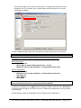
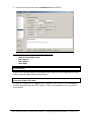
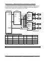
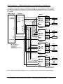
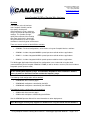
5 Gould Road, PO Box 2155
New London, NH 03257
Voice: (603) 526-9088
[email protected]
www.canarysystems.com
Using Campbell AVW2xx Vibrating Wire Interfaces
MultiLogger Application Note #21
Overview
The AVW2xx series of interfaces
from Campbell Scientific provide
high-quality vibrating wire
measurements by using a spectrum
analysis technique to output the gage
readings. This provides for highquality measurement of the vibrating
wire gages particularly in electrically
noisy environments as well as higher
resolution in electrically quiet environments.
There are several versions of the AVW2xx available:
•
AVW200 – For wired configurations, or for wireless using non-Campbell wireless solutions.
•
AVW206 – Includes integrated 900MHz spread spectrum radio for wireless applications.
•
AVW211 – Includes integrated 922MHz spread spectrum radio for wireless applications.
•
AVW216 – Includes integrated 2.4GHz spread spectrum radio for wireless applications.
This MultiLogger Application Note will detail the configuration issues involved for using the wired
(connected directly to the Campbell CR800 or CR1000) as well as wireless versions (units that include an
integrated spread spectrum radio).
Note: The Gage Types | Makes | Models supported in MultiLogger all use a range of 400-4000Hz
for the vibrating wire frequency range. This should be adequate for most installations. Contact
Canary Systems for direction to narrow or widen the frequency range.
The following wired configurations will be detailed:
•
AVW200 with direct connect gages.
•
AVW200 with multiplexers controlled by the MCU.
•
AVW200 with multiplexers controlled by the AVW200.
The following wireless configurations will be detailed:
•
AVW2xx with direct connect gages.
•
AVW2xx with multiplexers controlled by the AVW2xx.
See the AVW200 Operators Manual for more information on other deployments.
Note: MultiLogger currently only supports the AVWxx when using the CR800 and CR1000 MCU’s.
Using Campbell AVW2xx Vibrating Wire Interfaces – MultiLogger Application Note #21 – Page 1 of 13
Configuring the AVW2xx with CSI Device Configuration Software
Note: For proper function the CR800 FW must be v8 or higher, for the CR1000 v17 or higher.
The first step is getting familiar with the Device Configuration software and the settings of the AVW2xx. It
is very straight-forward to configure the unit for the wired or wireless deployments. The Device
Configuration software is included with LoggerNet or may be downloaded from the Campbell Scientific
website at http://www.campbellsci.com/downloads
Follow these steps:
1. Connect a 12V power supply to the AVW2xx, either using an AC Adaptor or the CR800 /CR1000
12V & G connections on the wiring panel.
2. Connect a standard RS-232 cable between the AVW2xx RS-232 port and the computers COM
port.
3. Launch the Device Configuration software. The AVW2xx is the first device in the Device Type list
so it will display by default when launching the software.
4. Press the Connect button to connect to the AVW2xx.
If you receive the error shown at right then check
connections and try again.
Using Campbell AVW2xx Vibrating Wire Interfaces – MultiLogger Application Note #21 – Page 2 of 13
Once connected you will see a main tab control, then a secondary tab control on the main
Deployment tab. The secondary tabs, Communications and Measurements are used for
configuring the AVW2xx.
See the AVW200 Operators Manual for information on the other tabs of the main tab control.
Note: For the AVW200 (non-wireless) the radio settings will be disabled.
The following are the main settings for configuring wired or wireless deployments:
Wired Deployments
• PakBus Address
• SDI-12 Address (found on Measurements tab – set to 0)
• Multiplexer Type (if using multiplexers – found on Measurements tab)
Wireless Deployments
• PakBus Address
• Multiplexer Type (if using multiplexers – found on Measurements tab)
• Hop Sequence
• Radio Address
• Power Mode
Note: For wireless deployments make sure the Hop Sequence, Net Address and Power Mode
match the RF4xx being used for communication with the AVW2xx.
If settings are changed press the Apply button to update the AVW2xx, otherwise press Disconnect.
A summary report will display, this can be saved as an XML file for updating other units or printed for
record keeping.
See the following section on configuring the RF4xx radio for wireless deployments.
Using Campbell AVW2xx Vibrating Wire Interfaces – MultiLogger Application Note #21 – Page 3 of 13
Configuring the RF4xx with CSI Device Configuration Software
For wireless applications the RF4xx spread spectrum radio must be configured for use with the AVW2xx.
Use Campbells Device Configuration software to configure the radio. The Device Configuration software
is included with LoggerNet or may be downloaded from the Campbell Scientific website at
http://www.campbellsci.com/downloads
Follow these steps:
1. Connect a 12V power supply to the RF4xx, either using an AC Adaptor or the coax power cable
which allows you to wire to the CR800 /CR1000 12V & G connections on the wiring panel.
Alternately you may connect the CS I/O connectors on the RF4xx and CR800/CR1000 using the
supplied SC12 cable.
2. Connect a standard RS-232 cable between the RF4xx RS-232 port and the computers COM port.
3. Launch the Device Configuration software. Scroll down the Device Type list to find the The
AVW2xx is the first device in the Device Type list so it will display by default when launching the
software.
4. Press the Connect button in Device Configuration
then press the green Configuration Mode button on
the RF4xx, located between the RS-232 connection
and antenna connection.
If you receive the error shown at right then check
connections and try again. The red power LED
should be illuminated on the RF4xx.
Using Campbell AVW2xx Vibrating Wire Interfaces – MultiLogger Application Note #21 – Page 4 of 13
5. Once connected you will be shown the Deployment tab for the RF4xx.
The following are the main settings for configuring the RF4xx:
•
•
•
•
Protocol (set to PakBus Aware)
Hop Sequence
Radio Address
Power Mode
Note: Make sure the Hop Sequence, Net Address and Power Mode match the AVW2xx being
used with RF4xx.
See the RF4xx Operators Manual for information on other settings but for most deployments no other
settings need to be modified from the factory defaults.
Note: Contact Canary Systems for direction with more complicated configurations including
use of static PakBus route maps.
If settings are changed press the Apply button to update the RF4xx, otherwise press Disconnect. A
summary report will display, this can be saved as an XML file for updating other units or printed for
record keeping.
Using Campbell AVW2xx Vibrating Wire Interfaces – MultiLogger Application Note #21 – Page 5 of 13
Wired Configuration – AVW200 with Direct Connect Gages
The following configuration depicts an AVW200 connected directly to the CR800 or CR1000, with gages
connected directly (no multiplexers) to the AVW200. Up to 2 gages may be directly connected to the
AVW200. The connection scheme utilizes SDI-12, this allows a single control port connection to the MCU.
Other configurations are possible including use of the RS-232 port. See the AVW200 Operators Manual
for more information on these configurations.
CR800/CR1000
AVW200
G
C3 (CR800)
C7 (CR1000)
C1 (SDI12)
C2 (CLK)
C3 (RES)
GND
1V+
1V1T+
1T-
BARE
RED
BLACK
WHITE
GREEN
VW#1
G
G
GND
2V+
2V2T+
2T-
G
12V
12V
BARE
RED
BLACK
WHITE
GREEN
VW#2
Note: Wire colors may
vary by manufacturer.
To configure MultiLogger use the following Direct Connect Gage Type | Make | Model selections:
Gage Type
Make
Model
Description
Vibrating Wire
Generic
AVW200 CH1 12V Digits
AVW200 CH1 12V Hz
AVW200 CH1 5V Digits
AVW200 CH1 5V Hz
AVW200 CH2 12V Digits
AVW200 CH2 12V Hz
AVW200 CH2 5V Digits
AVW200 CH2 5V Hz
Channel 1 with 12V excitation
Channel 1 with 12V excitation
Channel 1 with 5V excitation
Channel 1 with 5V excitation
Channel 2 with 12V excitation
Channel 2 with 12V excitation
Channel 2 with 5V excitation
Channel 2 with 5V excitation
Output
Units
Digits
Hz
Digits
Hz
Digits
Hz
Digits
Hz
Notes:
•
All of these Models use a frequency range of 400-4000Hz which should be adequate for most
installations. Contact Canary Systems for direction to narrow or widen the frequency range.
•
All of these Models use SDI-12 address 0. Contact Canary Systems for direction when using a
different SDI-12 address.
To read the Upper Channel (Temperature Device):
Device
Description
AVW200_YSI44005-°C
AVW200_YSI44005-°F
YSI type 44005 on Channel 1 or 2
YSI type 44005 on Channel 1 or 2
Output
Units
°C
°F
Using Campbell AVW2xx Vibrating Wire Interfaces – MultiLogger Application Note #21 – Page 6 of 13
Wired Configuration – AVW200 with Multiplexers Controlled by MCU (2-6 multiplexers)
The following configuration depicts an AVW200 connected directly to the CR800 or CR1000, with gages
connected to multiplexers controlled by the CR800 or CR1000. Note: A maximum of 2 multiplexers can
be connected to the CR800 using this configuration. See the following section for connecting up to 4
multiplexers to the CR800 and up to 10 multiplexers to the CR1000.
CR800/CR1000
AVW200
MUX#1
G
C3 (CR800)
C7 (CR1000)
C1 (SDI12)
C2 (CLK)
C3 (RES)
GND
1V+
1V1T+
1T-
Shield
COM Hi Odd
COM Lo Odd
COM Hi Even
COM Lo Even
G
G
12V
G
12V
ENABLE
CLOCK
GND
2V+
2V2T+
2T-
BARE
RED
BLACK
WHITE
GREEN
BARE
RED
BLACK
WHITE
GREEN
VW#1
VW#nn
MUX#2
Shield
COM Hi Odd
COM Lo Odd
COM Hi Even
COM Lo Even
C1
C2
C4 (CR800)
C8 (CR1000)
ENABLE
CLOCK
BARE
RED
BLACK
WHITE
GREEN
BARE
RED
BLACK
WHITE
GREEN
VW#1
VW#nn
Note: Wire colors may
vary by manufacturer.
Use the following configuration for the multiplexers:
Mux
1
Mux Model
As Req’d
Gage Type
Vibrating Wire
Channels
16/32
Wires
4/2
Enable
C1
2
As Req’d
Vibrating Wire
16/32
4/2
C2
3
4
5
6
As Req’d
As Req’d
As Req’d
As Req’d
Vibrating Wire
Vibrating Wire
Vibrating Wire
Vibrating Wire
16/32
16/32
16/32
16/32
4/2
4/2
4/2
4/2
C3 (CR1000)
C4 (CR1000)
C5 (CR1000)
C6 (CR1000)
Clock
C4 (CR800)
C8 (CR1000)
C4 (CR800)
C8 (CR1000)
C8 (CR1000)
C8 (CR1000)
C8 (CR1000)
C8 (CR1000)
Use the same gage types for Channel Configuration as shown in Direct Connect Section.
Note: Only use the Channel 1 Gage Types.
Using Campbell AVW2xx Vibrating Wire Interfaces – MultiLogger Application Note #21 – Page 7 of 13
Wired Configuration – AVW200 with Multiplexers Controlled by MCU (4-10 multiplexers)
The following configuration depicts an AVW200 connected directly to the CR800 or CR1000, with gages
connected to multiplexers controlled by the CR800 or CR1000. Up to 4 multiplexers can be controlled
when using the CR800, up to 10 (up to 12 can be controlled but MultiLogger is limited to 10) when using
the CR1000.
CR800/CR1000
AVW200
MUX#1
G
C3 (CR800)
C7 (CR1000)
C1 (SDI12)
C2 (CLK)
C3 (RES)
GND
1V+
1V1T+
1T-
Shield
COM Hi Odd
COM Lo Odd
COM Hi Even
COM Lo Even
G
ENABLE
CLOCK
G
12V
G
12V
C1
C2
C4 (CR800)
C8 (CR1000)
GND
2V+
2V2T+
2T-
BARE
RED
BLACK
WHITE
GREEN
BARE
RED
BLACK
WHITE
GREEN
VW#1
VW#nn
MUX#2
Shield
COM Hi Odd
COM Lo Odd
COM Hi Even
COM Lo Even
ENABLE
CLOCK
BARE
RED
BLACK
WHITE
GREEN
BARE
RED
BLACK
WHITE
GREEN
VW#1
VW#nn
MUX#3
Note: See tables on
following page for
Control Port
connections for 6, 8 and
10 multiplexers.
Shield
COM Hi Odd
COM Lo Odd
COM Hi Even
COM Lo Even
ENABLE
CLOCK
BARE
RED
BLACK
WHITE
GREEN
BARE
RED
BLACK
WHITE
GREEN
VW#1
VW#nn
MUX#4
Shield
COM Hi Odd
COM Lo Odd
COM Hi Even
COM Lo Even
ENABLE
CLOCK
BARE
RED
BLACK
WHITE
GREEN
BARE
RED
BLACK
WHITE
GREEN
VW#1
VW#nn
Note: Wire colors may
vary by manufacturer.
See the tables on the following page for the 4, 6, 8 and 10 multiplexer connection/configuration tables.
Using Campbell AVW2xx Vibrating Wire Interfaces – MultiLogger Application Note #21 – Page 8 of 13
Use the following configuration for 4 multiplexer configuration:
Mux
1
Mux Model
As Req’d
Gage Type
Vibrating Wire
Channels
16/32
Wires
4/2
Enable
C1
2
As Req’d
Vibrating Wire
16/32
4/2
C2
3
As Req’d
Vibrating Wire
16/32
4/2
C1
4
As Req’d
Vibrating Wire
16/32
4/2
C2
Clock
C4 (CR800)
C8 (CR1000)
C4 (CR800)
C8 (CR1000)
C4 (CR800)
C8 (CR1000)
C4 (CR800)
C8 (CR1000)
AVW2xx CH
1
1
2
2
Use the following configuration for 6 multiplexer configuration (CR1000 only):
Mux
1
2
3
4
5
6
Mux Model
As Req’d
As Req’d
As Req’d
As Req’d
As Req’d
As Req’d
Gage Type
Vibrating Wire
Vibrating Wire
Vibrating Wire
Vibrating Wire
Vibrating Wire
Vibrating Wire
Channels
16/32
16/32
16/32
16/32
16/32
16/32
Wires
4/2
4/2
4/2
4/2
4/2
4/2
Enable
C1
C2
C3
C1
C2
C3
Clock
C8
C8
C8
C8
C8
C8
AVW2xx CH
1
1
1
2
2
2
Clock
C8
C8
C8
C8
C8
C8
C8
C8
AVW2xx CH
1
1
1
1
2
2
2
2
Clock
C8
C8
C8
C8
C8
C8
C8
C8
C8
C8
AVW2xx CH
1
1
1
1
1
2
2
2
2
2
Use the following configuration for 8 multiplexer configuration (CR1000 only):
Mux
1
2
3
4
5
6
7
8
Mux Model
As Req’d
As Req’d
As Req’d
As Req’d
As Req’d
As Req’d
As Req’d
As Req’d
Gage Type
Vibrating Wire
Vibrating Wire
Vibrating Wire
Vibrating Wire
Vibrating Wire
Vibrating Wire
Vibrating Wire
Vibrating Wire
Channels
16/32
16/32
16/32
16/32
16/32
16/32
16/32
16/32
Wires
4/2
4/2
4/2
4/2
4/2
4/2
4/2
4/2
Enable
C1
C2
C3
C4
C1
C2
C3
C4
Use the following configuration for 10 multiplexer configuration (CR1000 only):
Mux
1
2
3
4
5
6
7
8
9
10
Mux Model
As Req’d
As Req’d
As Req’d
As Req’d
As Req’d
As Req’d
As Req’d
As Req’d
As Req’d
As Req’d
Gage Type
Vibrating Wire
Vibrating Wire
Vibrating Wire
Vibrating Wire
Vibrating Wire
Vibrating Wire
Vibrating Wire
Vibrating Wire
Vibrating Wire
Vibrating Wire
Channels
16/32
16/32
16/32
16/32
16/32
16/32
16/32
16/32
16/32
16/32
Wires
4/2
4/2
4/2
4/2
4/2
4/2
4/2
4/2
4/2
4/2
Enable
C1
C2
C3
C4
C5
C1
C2
C3
C4
C5
Note: Use the same gage types for Channel Configuration as shown in Direct Connect Section. Be
sure to use appropriate Channel type to match multiplexer to AVW2xx wiring.
Using Campbell AVW2xx Vibrating Wire Interfaces – MultiLogger Application Note #21 – Page 9 of 13
Wired Configuration – AVW200 with Multiplexers (up to 2)
The following configuration depicts an AVW200 connected directly to the CR800 or CR1000, with gages
connected to multiplexers controlled by the AVW200.
Note: You will need to configure the AVW2xx for which type of multiplexer is connected. See the
introductory section for information on using Campbells Device Configuration software to do this.
CR800/CR1000
COM1
COM2
(COM3)
(COM4)
For COM
connection use
CSI 178555
Cable
(example COM1
wiring below)
AVW200
GND
1V+
1VRS-232
1T+
1T-
COM3&4
CR1000
Only
C3 (RES)
C2 (CLK)
MUX#1
Shield
COM Hi Odd
COM Lo Odd
COM Hi Even
COM Lo Even
ENABLE
CLOCK
BARE
RED
BLACK
WHITE
GREEN
BARE
RED
BLACK
WHITE
GREEN
VW#1
VW#nn
MUX#2
G
G
12V
CR800/CR1000
C1 (TD)
C2 (RD)
G
12V
GND
2V+
2V2T+
2T-
Shield
COM Hi Odd
COM Lo Odd
COM Hi Even
COM Lo Even
AVW200 DB-9
ENABLE
CLOCK
3
2
5
BARE
RED
BLACK
WHITE
GREEN
BARE
RED
BLACK
WHITE
GREEN
VW#1
VW#nn
Note: Wire colors may
vary by manufacturer.
Each multiplexer would be configured separately in MultiLogger. When configuring the multiplexers use
the Multiplexer Model AVW2xx. Configure the Channels to match the multiplexer configuration. Up to 16
vibrating wire gages with temperature can be read, or 32 channels without temperature.
Use the following Gage Type | Make | Model selections for the Multiplexer 1 Channel Configuration:
Gage Type
Vibrating Wire
Make
AVW2xx
Model
COM1 PB200 CH1 Digits
COM2 PB200 CH1 Digits
COM3 PB200 CH1 Digits
COM4 PB200 CH1 Digits
Description
PakBus ID 200 CH1 connected to Com1
PakBus ID 200 CH1 connected to Com2
PakBus ID 200 CH1 connected to Com3
PakBus ID 200 CH1 connected to Com4
Output Units
Digits
Digits
Digits
Digits
Use the following Gage Type | Make | Model selections for the Multiplexer 2 Channel Configuration:
Gage Type
Vibrating Wire
Make
AVW2xx
Model
COM1 PB200 CH2 Digits
COM2 PB200 CH2 Digits
COM3 PB200 CH2 Digits
COM4 PB200 CH2 Digits
Description
PakBus ID 200 CH2 connected to Com1
PakBus ID 200 CH2 connected to Com2
PakBus ID 200 CH2 connected to Com3
PakBus ID 200 CH2 connected to Com4
Output Units
Digits
Digits
Digits
Digits
Note: These gage types all use 12 volt excitation which should be appropriate for most gages.
Contact Canary Systems if you experience unexplained measurement instability.
To read the Upper Channel (Temperature Device):
Device
Description
AVW200_YSI44005-°C
AVW200_YSI44005-°F
YSI type 44005 on Channel 1 or 2
YSI type 44005 on Channel 1 or 2
Output
Units
°C
°F
Using Campbell AVW2xx Vibrating Wire Interfaces – MultiLogger Application Note #21 – Page 10 of 13
Wireless Configurations – AVW200 with Instruments Directly Connected
The following configuration depicts an AVW200 connected wirelessly to the CR800 or CR1000 with
gages connected directly (no multiplexers) to the AVW200. Up to 2 gages may be directly connected to
the AVW200. The radio is a matching RF4xx, connected to the MCU on the CS I/O connection using the
SC12 cable. See the introductory sections on configuring the AVW2xx and RF4xx for wireless operation.
Contact Canary Systems for assistance with using other communications interfaces for the RF4xx
– the RS-232 port and COM1-COM4 (COM1-COM2 on CR800) can be supported.
CR800/CR1000
AVW2xx
RF4xx
CS I/O
GND
1V+
1V1T+
1T-
CS I/O
SC12 Cable
Power
Supply
G
12V
G
12V
Power
Supply
G
G
12V
12V
GND
2V+
2V2T+
2T-
BARE
RED
BLACK
WHITE
GREEN
BARE
RED
BLACK
WHITE
GREEN
VW#1
VW#2
Note: Wire colors may
vary by manufacturer.
To configure MultiLogger use the following Direct Connect Gage Type | Make | Model selections:
Gage Type
Vibrating Wire
Make
AVW2xx
Model
SDC7 PB2nn CH1 Digits
SDC7 PB2nn CH2 Digits
Description
PakBus 2nn CH1 connected to SDC7 (CS I/O)
PakBus 2nn CH2 connected to SDC7 (CS I/O)
Output Units
Digits
Digits
Where;
PB2nn: Select the actual address for the device in use.
Note that PakBus addresses 200-215 are currently supported. Contact Canary Systems if your
application requires deployment of more than 16 AVW2xx’s.
Note: These gage types all use 12 volt excitation which should be appropriate for most gages.
Contact Canary Systems if you experience unexplained measurement instability.
To read the Upper Channel (Temperature Device):
Device
Description
AVW200_YSI44005-°C
AVW200_YSI44005-°F
YSI type 44005 on Channel 1 or 2
YSI type 44005 on Channel 1 or 2
Output
Units
°C
°F
Using Campbell AVW2xx Vibrating Wire Interfaces – MultiLogger Application Note #21 – Page 11 of 13
Wireless Configurations – AVW200 with Multiplexers (up to 2)
The following configuration depicts an AVW200 connected wirelessly to the CR800 or CR1000 with
gages connected to multiplexers connected to the AVW200. Up to 2 multiplexers may be directly
connected to the AVW200. The multiplexers may be configured for 16 channel mode to include reading
the temperature, or 32 channels without temperature.
Note: You will need to configure the AVW2xx for which type of multiplexer is connected. See the
introductory section for information on using Campbells Device Configuration software to do this.
CR800/CR1000
RF4xx
CS I/O
AVW2xx
GND
1V+
1V1T+
1T-
CS I/O
SC12 Cable
Power
Supply
G
12V
G
12V
C3 (RES)
C2 (CLK)
Power
Supply
G
12V
MUX#1
Shield
COM Hi Odd
COM Lo Odd
COM Hi Even
COM Lo Even
ENABLE
CLOCK
BARE
RED
BLACK
WHITE
GREEN
BARE
RED
BLACK
WHITE
GREEN
MUX#2
G
12V
GND
2V+
2V2T+
2T-
Shield
COM Hi Odd
COM Lo Odd
COM Hi Even
COM Lo Even
ENABLE
CLOCK
BARE
RED
BLACK
WHITE
GREEN
BARE
RED
BLACK
WHITE
GREEN
VW#1
VW#nn
Note: Wire colors
may vary by
manufacturer.
VW#1
VW#nn
Each multiplexer would be configured separately in MultiLogger. When configuring the multiplexers use
the Multiplexer Model AVW2xx. Configure the Channels to match the multiplexer configuration. Up to 16
vibrating wire gages with temperature can be read, or 32 channels without temperature.
Use the following Gage Type | Make | Model selections for the Multiplexer 1 Channel Configuration:
Gage Type
Vibrating Wire
Make
AVW2xx SDC7
Model
PB200 CH1 12V Digits
PB200 CH1 12V Hz
PB200 CH1 5V Digits
PB200 CH1 5V Hz
Description
PakBus 200 CH1 with 12V excitation
PakBus 200 CH1 with 12V excitation
PakBus 200 CH1 with 5V excitation
PakBus 200 CH1 with 5V excitation
Output Units
Digits
Hz
Digits
Hz
Use the following Gage Type | Make | Model selections for the Multiplexer 2 Channel Configuration:
Gage Type
Vibrating Wire
Make
AVW2xx SDC7
Model
PB200 CH2 12V Digits
PB200 CH2 12V Hz
PB200 CH2 5V Digits
PB200 CH2 5V Hz
Description
PakBus 200 CH2 with 12V excitation
PakBus 200 CH2 with 12V excitation
PakBus 200 CH2 with 5V excitation
PakBus 200 CH2 with 5V excitation
Output Units
Digits
Hz
Digits
Hz
Note: PakBus addresses 200-215 are currently supported however MultiLogger is limited to 10
multiplexers. Select the appropriate PakBus address to match the device in use.
See the previous section for configuring the temperature measurement.
Using Campbell AVW2xx Vibrating Wire Interfaces – MultiLogger Application Note #21 – Page 12 of 13
Troubleshooting
The Campbell AVW200 Operators Manual has additional information on trouble-shooting, particularly for
the wireless deployments.
It also contains information on using the Device Configuration software to view the vibrating wire signal
responses to trouble-shoot poorly performing gages or noisy environments.
This section will provide guidelines to aid in trouble-shooting the commonly encountered issues.
MultiLogger provides several metrics to aid in troubleshooting, as follows:
•
When instruments are disconnected or otherwise fail to read the Text Monitor will show
OVERRANGE, or a stored value of -99999. The minimum amplitude used to verify a gage
measurement is 0.1mV This may need to be adjusted for some instrument types.
•
When the AVW2xx is disconnected or otherwise unable to communicate with the MCU the Text
Monitor will display a value of -99998.
•
UserLoc(1) holds the output amplitude of the vibrating wire signal. This can be added to the Text
Monitor (you’ll need to turn off Auto Configure Locations in the Configure | Preferences form
of Logger to view this location).
•
Additional metrics such as Signal-to-Noise Ratio (SNR) can be shown in the UserLocs by editing
the instruction file for the selected Gage Type | Make | Model (press the gear button and remove
the comment characters from the lines of programming).
Follow these steps to resolve the commonly encountered issues:
1. Check all power connections. When using the RF4xx make sure the red PWR led is lit.
2. Check all wiring connections. Use the diagrams provided in this Application Note.
3. Use the Device Configuration software to check settings in the AVW2xx per instructions outlined
previously. If using SDI-12 with directly connected AVW2xx’s check the SDI-12 address setting.
This should be set to 0. If using other interfaces double-check the PakBus ID.
4. If using a wireless deployment use the Device Configuration software to check that the radio and
AVW2xx wireless settings match. The Hop Sequence and Net Address MUST MATCH. Also
the Power Mode should match, other combinations to reduce power consumption should be
tested thoroughly prior and during deployment.
5. If using a wireless deployment then check all antenna cabling and connections. Check signal
strength using the RF4xx diagnostics.
6. If using multiplexers with the AVW2xx make sure the correct multiplexer Model is selected. If
using the MCU to control multiplexers then select the model of the multiplexer attached. If using
the AVW2xx to control to the multiplexers then make sure the multiplexer Model is set to
AVW2xx.
7. Check that the Gage Type | Make | Model selected for each channel matches the wiring and
AVW2xx configuration.
Using Campbell AVW2xx Vibrating Wire Interfaces – MultiLogger Application Note #21 – Page 13 of 13