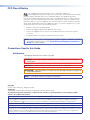
1
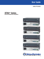
User Guide
Audio Products
XTRA™ Series
Half-Rack Audio Power Amplifiers
68-2354-01 Rev. A
02 14
Safety Instructions
Safety Instructions • English
WARNING: This symbol,
, when used on the product, is intended to
alert the user of the presence of uninsulated dangerous voltage within the
product’s enclosure that may present a risk of electric shock.
ATTENTION: This symbol,
, when used on the product, is intended
to alert the user of important operating and maintenance (servicing)
instructions in the literature provided with the equipment.
For information on safety guidelines, regulatory compliances, EMI/EMF
compatibility, accessibility, and related topics, see the Extron Safety and
Regulatory Compliance Guide, part number 68-290-01, on the Extron website,
www.extron.com.
Instructions de sécurité • Français
AVERTISSEMENT: Ce pictogramme,
, lorsqu’il est utilisé sur le
produit, signale à l’utilisateur la présence à l’intérieur du boîtier du produit
d’une tension électrique dangereuse susceptible de provoquer un choc
électrique.
ATTENTION: Ce pictogramme,
, lorsqu’il est utilisé sur le produit, signale
à l’utilisateur des instructions d’utilisation ou de maintenance importantes
qui se trouvent dans la documentation fournie avec le matériel.
Pour en savoir plus sur les règles de sécurité, la conformité à la réglementation,
la compatibilité EMI/EMF, l’accessibilité, et autres sujets connexes, lisez les
informations de sécurité et de conformité Extron, réf. 68-290-01, sur le site
Extron, www.extron.fr.
Sicherheitsanweisungen • Deutsch
WARNUNG: Dieses Symbol
auf dem Produkt soll den Benutzer darauf
aufmerksam machen, dass im Inneren des Gehäuses dieses Produktes
gefährliche Spannungen herrschen, die nicht isoliert sind und die einen
elektrischen Schlag verursachen können.
Инструкция по технике безопасности • Русский
ПРЕДУПРЕЖДЕНИЕ:
Weitere Informationen über die Sicherheitsrichtlinien, Produkthandhabung,
EMI/EMF-Kompatibilität, Zugänglichkeit und verwandte Themen finden Sie in
den Extron-Richtlinien für Sicherheit und Handhabung (Artikelnummer
68-290-01) auf der Extron-Website, www.extron.de.
Instrucciones de seguridad • Español
ADVERTENCIA: Este símbolo,
, cuando se utiliza en el producto,
avisa al usuario de la presencia de voltaje peligroso sin aislar dentro del
producto, lo que puede representar un riesgo de descarga eléctrica.
ATENCIÓN: Este símbolo,
, cuando se utiliza en el producto, avisa
al usuario de la presencia de importantes instrucciones de uso y
mantenimiento recogidas en la documentación proporcionada con el
equipo.
Para obtener información sobre directrices de seguridad, cumplimiento
de normativas, compatibilidad electromagnética, accesibilidad y temas
relacionados, consulte la Guía de cumplimiento de normativas y seguridad de
Extron, referencia 68-290-01, en el sitio Web de Extron, www.extron.es.
, если указан на продукте,
внутри корпуса продукта, которое может привести к поражению электрическим
током.
ВНИМАНИЕ: Данный символ,
, если указан на продукте,
предупреждает пользователя о наличии важных инструкций
по эксплуатации и обслуживанию в руководстве,
прилагаемом к данному оборудованию.
Для получения информации о правилах техники безопасности,
соблюдении нормативных требований, электромагнитной
совместимости (ЭМП/ЭДС), возможности доступа и других
вопросах см. руководство по безопасности и соблюдению
нормативных требований Extron на сайте Extron: www.extron.ru,
номер по каталогу - 68-290-01.
Chinese Simplified(简体中文)
警告:
产品上的这个标志意在警告用户该产品机壳内有暴露的危险 电压,有触电危险。
注 意:
产品上的这个标志意在 提示用户设备随附的用户手册中有
重要的操作和维护(维修)说明。
关于我们产品的安全指南、遵循的规范、EMI/EMF 的兼容性、无障碍
使用的特性等相关内容,敬请访问 Extron 网站 www.extron.cn,参见 Extron
安全规范指南,产品编号 68-290-01。
Chinese Traditional(
警告:
VORSICHT: Dieses Symbol
auf dem Produkt soll dem Benutzer in der
im Lieferumfang enthaltenen Dokumentation besonders wichtige Hinweise
zur Bedienung und Wartung (Instandhaltung) geben.
Данный символ,
предупреждает пользователя о наличии неизолированного опасного напряжения
)
若產品上使用此符號,是為了提醒使用者,產品機殼內存在著
可能會導致觸電之風險的未絕緣危險電壓。
注意
若產品上使用此符號,是為了提醒使用者。
有關安全性指導方針、法規遵守、EMI/EMF 相容性、存取範圍和相關主題的詳
細資訊,請瀏覽 Extron 網站:www.extron.cn,然後參閱《Extron 安全性與法
規遵守手冊》,準則編號 68-290-01。
Japanese
警告: この記号
が製品上に表示されている場合は、筐体内に絶縁されて
いない高電圧が流れ、感電の危険があることを示しています。
注意: この記号
が製品上に表示されている場合は、本機の取扱説明書に 記載されてい
る重要な操作と保守(整備)の指示についてユーザーの 注意を喚起するものです。
安全上のご注意、法規厳守、EMI/EMF適合性、その他の関連項目に
ついては、エクストロンのウェブサイト www.extron.jp より『Extron Safety and
Regulatory Compliance Guide』(P/N 68-290-01) をご覧ください。
Korean
경고: 이 기호
가 제품에 사용될 경우, 제품의 인클로저 내에 있는 접지되지 않은 위험한
전류로 인해 사용자가 감전될 위험이 있음을 경고합니다.
주의:
이 기호
가 제품에 사용될 경우, 장비와 함께 제공된 책자에 나와 있는 주요 운영 및
유지보수(정비) 지침을 경고합니다.
안전 가이드라인, 규제 준수, EMI/EMF 호환성, 접근성, 그리고 관련 항목에
대한 자세한 내용은 Extron 웹 사이트(www.extron.co.kr)의 Extron 안전 및
규제 준수 안내서, 68-290-01 조항을 참조하십시오.
FCC Class B Notice
This equipment has been tested and found to comply with the limits for a
Class B digital device, pursuant to part 15 of the FCC rules. These limits provide reasonable
protection against harmful interference in a residential installation. This equipment generates,
uses, and can radiate radio frequency energy and, if not installed and used in accordance with the
instructions, may cause harmful interference to radio communications. There is no guarantee that
interference will not occur. If this equipment does cause interference to radio or television reception,
which can be determined by turning the equipment off and on, you are encouraged to try to correct
the interference by one or more of the following measures:
•
•
•
Reorient or relocate the receiving antenna.
•
Consult the dealer or an experienced radio/TV technician for help.
Increase the separation between the equipment and receiver.
Connect the equipment into an outlet on a circuit different from that to which the receiver is
connected.
NOTE: For more information on safety guidelines, regulatory compliances, EMI/EMF compatibility,
accessibility, and related topics, see the “Extron Safety and Regulatory Compliance
Guide” on the Extron website.
Conventions Used in this Guide
Notifications
The following notifications are used in this guide:
WARNING: A warning indicates a situation that has the potential to result in death or
severe injury.
CAUTION: A caution indicates a situation that may result in minor injury.
ATTENTION: Attention indicates a situation that may damage or destroy the product or
associated equipment.
NOTE: A note draws attention to important information.
Copyright
© 2014 Extron Electronics. All rights reserved.
Trademarks
All trademarks mentioned in this guide are the properties of their respective owners.
The following registered trademarks(®), registered service marks(SM), and trademarks(TM) are the property of RGB
Systems, Inc. or Extron Electronics:
Registered Trademarks(®)
AVTrac, Cable Cubby, CrossPoint, eBUS, EDID Manager, EDID Minder, Extron, Flat Field, GlobalViewer, Hideaway, Inline, IP Intercom,
IP Link, Key Minder, LockIt, MediaLink, PlenumVault, PoleVault, PowerCage, PURE3, Quantum, SoundField, SpeedMount, SpeedSwitch,
System INTEGRATOR, TeamWork, TouchLink, V‑Lock, VersaTools, VN‑Matrix, VoiceLift, WallVault, WindoWall, XTP and XTP Systems
Registered Service Mark(SM) : S3 Service Support Solutions
Trademarks(™)
AAP, AFL (Accu‑Rate Frame Lock), ADSP (Advanced Digital Sync Processing), Auto‑Image, CDRS (Class D Ripple Suppression), DDSP (Digital
Display Sync Processing), DMI (Dynamic Motion Interpolation), Driver Configurator, DSP Configurator, DSVP (Digital Sync Validation Processing),
FastBite, FOXBOX, IP Intercom HelpDesk, MAAP, MicroDigital, ProDSP, QS-FPC (QuickSwitch Front Panel Controller), Scope‑Trigger, SIS,
Simple Instruction Set, Skew‑Free, SpeedNav, Triple‑Action Switching, XTRA, ZipCaddy, ZipClip
Contents
Introduction................................................... 1
Operation........................................................ 9
About this Manual............................................ 1
Terms Used in this Manual............................ 1
Features........................................................... 1
Front Panel Features and Operation................. 9
Rear Panel Features and Operation................ 11
Remote Volume Control.............................. 17
Controlling Multiple Amplifiers with One
Volume Controller...................................... 18
Bridged Mono Output................................. 19
Installation..................................................... 3
Application Examples....................................... 3
Mounting the XTRA Series Amplifiers................ 4
Tabletop Use................................................ 4
UL Guidelines for Rack Mounting.................. 4
Rack Mounting............................................. 5
Flexible Conduit Adapter Kit Installation........ 6
Troubleshooting.......................................... 20
Amplifier Fails to Exit
Standby Mode Promptly................................ 20
Amplifier Enters Standby Mode
Too Early....................................................... 21
Limiter/Protect LED Warning Indicators.......... 21
Over Temp Indicator LED................................ 21
XTRA Series Half-Rack Audio Power Amplifiers • Contents
v
Introduction
About this Manual
This manual contains information about the Extron XTRA Series of power amplifiers.
• XPA 1002 two-channel stereo audio power amplifier
• XPA 1002 Plus two-channel stereo audio power amplifier
• XPA 2001-70V mono audio power amplifier
• XPA 2001-100V mono audio power amplifier
Terms Used in this Manual
The terms “amplifier” and “power amplifier” are used interchangeably in this manual to refer
to all of the XPA models. “XPA 1002” refers to the 1002 and the 1002 Plus. ”XPA 2001”
refers to both the XPA 2001-70V and the XPA 2001-100V.
Features
Inputs — Balanced or unbalanced stereo or mono on a 3.5 mm, 5-pole captive screw
connector.
Speaker outputs — Screw-lock, 5 mm captive screw connectors enable simple, secure
connections with 22 AWG to 12 AWG speaker cables.
Continuous power output for larger rooms —
• XPA 1002: 60 watts rms per channel at 8 ohms; 100 watts rms per channel at 4 ohms.
• XPA 1002 Plus: 100 watts rms per channel at 4 and 8 ohms.
• XPA 2001-70V: 200 watts rms for 70 volt speaker systems.
• XPA 2001-100V: 200 watts rms for 100 volt speaker systems.
Professional grade amplifier design —
• The XPA 1002 and 1002 Plus features less than 0.05% total harmonic distortion plus
noise, and better than 105 dB signal-to-noise ratio.
• The XPA 2001 features less than 0.1% total harmonic distortion plus noise, and better
than 100 dB signal to noise ratio.
ENERGY STAR® qualified amplifier — The XTRA Series of amplifiers are energy efficient
products that conserve energy and reduce operating costs.
Highly efficient Class D amplifier design — The XTRA Series of amplifiers generate
substantially less heat than conventional amplifier designs, making them ideal for installation
in equipment racks and lecterns with very limited ventilation. They consume 10 watts when
idle and less than 1 watt in standby mode.
XTRA Series Half-Rack Audio Power Amplifiers • Introduction
1
Extron patented CDRS — Class D ripple suppression — A patented, exclusive
technology from Extron that eliminates the high frequency switching ripple and EMI
emissions found in typical Class D amplifiers. CDRS enables Extron power amplifiers to be
situated near wireless AV devices without RF interference.
Convection cooled — The XTRA Series of amplifiers are convection cooled without the
need for fans, ensuring quiet, reliable operation.
Ultra low inrush current — no need for power sequencing — Allows many XTRA
series amplifiers to be powered on simultaneously without overloading power circuits.
This eliminates the need for power sequencing.
Flexible Conduit Adapter Kit — Suitable for use in other environmental air space in
accordance with section 300.22, (C) of the National Electrical Code only when used with
optional Flexible Conduit Adapter Kit.
Auto-standby with fast power-up — The amplifiers automatically enter into a standby
mode after 25 minutes of inactivity, + or - 5 minutes, dramatically reducing power
consumption. They quickly return to full power status upon signal detection.
Rear panel attenuation (level) controls — Provide attenuation of input signals for
setting proper audio system gain staging as well as two-zone applications. They are
located on the rear panel to prevent unauthorized or accidental tampering of the level
adjustments.
Multiple protection circuits — Activates during excessive clipping, output shorts,
thermal overload, or DC faults to prevent damage to the amplifier and speakers.
Remote standby port — Enables the amplifiers to be remotely powered down when not
in use, reducing operating cost.
Remote volume and mute control port — Allows the XPA 1002 series and the XPA
2001 series to be remotely controlled using the optional Extron VCM 100 Series volume
and mute or VC 50 volume controllers.
Bridgeable outputs — The power output of the XPA 1002 and XPA 1002 Plus can be
effectively doubled by bridging the output. A mono source is wired to both the left and
right input while the output is wired for bridged operation. Bridging allows power to be
output at 200 watts into 8 ohms. The minimum load impedance when bridging is 8 ohms
(see the wiring instructions on page 19).
Front and rear-mounted signal and protection indication LEDs — Provide
convenient indication of amplifier operation from both sides of an equipment rack.
Internal international power supply — The 100-240 VAC, 50-60 Hz universal power
supply provides worldwide power compatibility.
XTRA Series Half-Rack Audio Power Amplifiers • Introduction
2
Installation
This section discusses how to install the XTRA Series of audio power amplifiers.
Topics that are covered, include:
• Application Examples
• Mounting the XTRA Series Amplifier
WARNING: Failure to follow these instructions may result in serious injury.
Installation and service must be performed by authorized personnel only (see
UL Guidelines for Rack Mounting on page 4).
Application Examples
The following illustrations are application examples for the XPA 1002 series and the
XPA 2001 series.
S
UT
TP
8Ω
/ 4Ω
OU
2
1
A
50m
10V
G
2
ION
AT
2
NU
TE
AT
1
02
A 10
XP
Extron
XPA 1002
1
2
12
14
18
26
∞
60H
z
, 50-
12
10 8 6 14
4
2 ∞
0
STANDBY
TE
MO
RE
S
UT
INP
G
S2
RIN
WI
AS
CL
1
V
C
G
10 8 6
4
2
0
CT
L
TE
RO
0.5A
R/P
0V
ITE
-24
100
LIM
NA
SIG
Power
Amplifier
Extron
SI 28
TouchLink
Control
System
VCR
DVD
DOC
CAM
LAPTOP
Surface-mount
Speakers
PC
ON
OFF
DISPLAY
MUTE
SCREEN
UP
SCREEN
DOWN
TCP/IP
®
100
INPUT
IR
RELAY
LINK
3
ACT
1
3
1
COM
RX
IPL
TX
250
R
4
3
2
4
2
4
2
3
2
-23
RS
A
B
1
1
2
T
PU
OUT
L
R
L
RS-232
6
DIO3
T
INPU 4
5
8
R
7
AU
2
1
T
L
Y
R
PU
OUT
ED
LIST 3
1T2 .
U S I.T.E
C
Y,
B
RG RY,
B-
6
8
I
B
DV
RG
B
7
RG
3 YC
Y
R1 VID
Extron
IN1508
Y
B-
I
V
-240
100
0Hz
50-6
N
T
Y
VID
P
U
5
4
2
Scaling Presentation
Switcher
Projector
PC
DVI Output
Laptop
VCR
Document
Camera
DVD Player
PC
Figure 1. XPA 1002 Series Application Example
XTRA Series Half-Rack Audio Power Amplifiers • Installation
3
Extron
SI 26CT
Two-way Ceiling
Speakers
Extron
XPA 2001-70V
Power
Amplifier
T
TPU
50m
10V
G
V OU
ING
SS
2 WIR
CLA
)R
HPF
STANDBY
70
OTE
REM A
UTS
INP
GlobalViewer
MED
L (SUM
ON
V
ATI
C
G
ENU
ATT
V
AV Resource
Management and
Remote Control
Application
-70
01
A 20
XP
12
14
18
26
∞
0Hz
0.5A
10 8 6
4
2
0
80
Hz
OFF
T
, 50-6
TEC
RO
R/P
ITE
240V
100-
LIM
NAL
SIG
TCP/IP
Network
Extron
MPX 423 A
Media Presentation
Matrix
2
-23
RS
LE
RIB
VA
O
IDE
S-V
L
EO
VID
L
ER
UT
MP
CO
L
T
OU
O IN
IDE
S-V 11
T
OU
ER
UT
MP
CO
T
OU
IN
1
2
9
L
L
1
2
R
L
3
4
L
R
L
1
2
R
L
L
3
4
R
L
1
2
R
L
3
4
R
R
3
4
R
R
O
U
T
P
U
T
S
R
R
R
R
0V
-24
PC (2)
100
1
Video
S-video
10
2
5
8
VGA
6
1
ER
UT
MP
CO
0.3A
C
O
N
T
T
SE
RE
R
K
LIN
O
L ACT
R
12
1
EO
VID 7
I
N
P
U
T
S
O
I
U L
N
T
P
P
L
U
U
T
T
S
S
IN
3
2
4
Video
2
S-video
0 Hz
50/6
Projector
VGA
Flat Panel Display
Laptop (2)
DVD (4)
VCR (4)
Figure 2. XPA 2001 Series Application Example
Mounting the XTRA Series Amplifiers
The XPA 1002 series and XPA 2001 series of audio amplifiers can be set on a table,
mounted on a rack shelf, or mounted in the plenum space above a ceiling-mounted
projector.
Tabletop Use
Four self-adhesive rubber feet are included with the audio amplifier.
For tabletop use, attach one foot at each corner of the bottom side of the unit and place
the unit in the desired location.
UL Guidelines for Rack Mounting
The following Underwriters Laboratories (UL) guidelines pertain to the installation of the
equipment in a rack.
1. Elevated operating ambient — If installed in a closed or multi-unit rack assembly,
the operating ambient temperature of the rack environment may be greater than room
ambient. Therefore, consider installing the equipment in an environment compatible
with the maximum ambient temperature specified by the manufacturer [Tma = +32 to
+122 °F (0 to +50 °C)].
XTRA Series Half-Rack Audio Power Amplifiers • Installation
4
2. Reduced air flow — Installation of the equipment in a rack should be such that the
amount of air flow required for safe operation of the equipment is not compromised.
3. Mechanical loading — Mounting of the equipment in the rack should be such that a
hazardous condition is not achieved due to uneven mechanical loading.
4. Circuit overloading — Consideration should be given to the connection of the
equipment to the supply circuit and the effect that overloading of the circuits might
have on overcurrent protection and supply wiring. Appropriate consideration of
equipment nameplate ratings should be used when addressing this concern.
5. Reliable earthing (grounding) — Reliable earthing of rack-mounted equipment
should be maintained. Particular attention should be given to supply connections
other than direct connections to the branch circuit (such as the use of power strips).
Rack Mounting
The XPA 1002 series and XPA 2001 series can be mounted in a rack shelf using the
optional RSU 129 1U Universal rack shelf or the 1U Basic rack shelf, as follows.
1. If feet were installed on the bottom of the amplifier, remove them.
2. Place the amplifier on one half of the rack shelf.
3. Align the front of the amplifier with the front of the shelf, and align the threaded holes on the bottom of the amplifier with the holes in the rack shelf.
4. Attach the amplifier to the rack shelf with the two provided 4-40 x 3/16” machine screws.
5. Insert the screws from the underside of the shelf, and securely fasten them into diagonally-opposite corners.
1U Universal Rack Shelf
1/2 Rack Width Front False
Faceplate
Front false
faceplate
uses 2
screws.
(2) 4-40 x 3/16"
Screws
Use 2 mounting holes on
opposite corners.
ATTENTION: Using screws longer than
3/16” will damage the unit and void the
warranty.
Figure 3. Rack Mounting of the Amplifier
6. Attach the false front panel (provided with rack shelf) to the unoccupied side of the
rack (as shown above), or install a second half-rack-width device in that side by
repeating steps 1 through 5.
7. Attach the rack shelf to the rack using four 10-32 x ¾” bolts (provided). Insert the
bolts through #10 beveled washers, then through the holes in the rack, as shown
above.
XTRA Series Half-Rack Audio Power Amplifiers • Installation
5
Rack Mounting Ventilation Recommendations
Excessive heat can decrease the optimal lifetime of the power amplifier. An over temp
indicator LED on the front panel of the amplifier lights red whenever the recommended
operating temperature has been exceeded (see Front Panel Features and Operation
on page 9).
To reduce the chances for an over temp condition, the XPAs should be arranged in a
rack environment so that adequate airflow is available both above and below the XPA
whenever possible. No more than two XPAs should be arranged one-on-top-of-the-other
in a rack without an open space between them, as shown in the following illustration. An
XPA can also be arranged above or below another non-XPA device, but there must be an
open space both above and below those devices.
Ven
t
Ven
t
Ven
t
Ven
t
Sp
ace
Sp
ace
Sp
Ven
t
ace
Sp
ace
Ven
t
Sp
ace
Sp
ace
Figure 4. Allow Sufficient Spacing for Adequate Ventilation
Flexible Conduit Adapter Kit Installation
WARNING: Failure to follow these instructions may result in serious injury.
• The circuit breaker used for this connection should be rated no lower than 20
amps and no greater than 30 amps.
• This unit must be installed in accordance with the National Electrical Code and
with all local codes.
• An ALL-POLE MAINS SWITCH with a contact separation of at least 3 mm in
each pole shall be incorporated in the electrical installation of the building. The
installation shall be carried out in accordance with all applicable installation rules.
• Installation and service must be performed by a qualified electrician only.
• Make sure that the source device and the XPA are turned off and disconnected
from the power source before you begin.
ATTENTION: A UL listed electrical distribution box is recommended for the
termination of the conduit opposite the XPA (see the following UL Requirements
section on page 7).
XTRA Series Half-Rack Audio Power Amplifiers • Installation
6
The optional Flexible Conduit Adapter Kit consists of:
• One EMT adapter plate
• One 6-foot long electrical conduit
• Three 7.5 feet, 18-gauge spade connector power wires
• One UL-rated zip tie wrap
• Three auxiliary crimp style spade connectors designed for 14- to 16-gauge wires
NOTE: If needed, Extron recommends using a UL-rated crimp tool to terminate
the spade connectors. One recommended choice is the Molex crimp tool.
The kit provides a convenient means to replace the IEC power cord of the XPA with
conduit, where required by local codes.
UL Requirements
The UL requirements listed below pertain to the installation of the flexible conduit onto a
XPA 1002 or XPA 2001.
• This unit is not to be used beyond its rated voltage range.
• This unit must be wired to a UL listed distribution box.
NOTE: The UL approved electrical distribution box is not included with either
the XPA or the Flexible Conduit Adapter Kit. The installer is responsible for
obtaining and installing the box.
Installing the Flexible Conduit Kit
ATTENTION: Electrostatic discharge (ESD) can damage IC chips even though you
cannot feel it. You must be electrically grounded before touching anything inside the
XPA. A grounding wrist strap is recommended.
Install flexible conduit to the XPA by following the steps below.
1. Unplug the IEC power cord from the power amplifier.
2. Remove the 8 screws from the top and sides of the XPA and lift off the cover (see
figure 5).
Lift Cover Straight Up
Remove (8)
screws
UTS
TP
8Ω
/ 4Ω
OU
2
1
mA
50
V
10
G
2
00
A1
XP
1
2
2
G
IN
SS
IR
2W
CLA
1
N
IO
AT
NU
TE
AT
1
STANDBY
TE
MO
RE
TS
PU
IN
2
V
C
G
10 8 6
12
4
2
10 8 6 14
12
0
4
14
2
18
0
26
∞
∞
A,
z
-60H
CT
TE
RO AL
/P
N
ITER SIG
50
0.5
0V
0-24
10
LIM
Figure 5. Removing the Cover
XTRA Series Half-Rack Audio Power Amplifiers • Installation
7
3. Remove the 2 screws holding the hot (Line) and neutral wires from the terminal block
on the PCB (see figure 6).
Blue Wire
Brown Wire
100-
240V
1.3A
50-6
0H
z
N
L
Remove nut
Remove screws
(both sides) to release
IEC connector plate.
Figure 6. Removing the IEC Connector
4. Remove the ground wire nut from the grounding stud on the bottom of the enclosure,
as shown above.
5. Remove the 2 screws from the IEC plate, and remove the IEC connector plate and
the attached wires through the rear panel of the XPA, as shown above.
6. Thread the 18-gauge power wires through the length of the electrical conduit tube.
7. Install the EMT adapter plate with conduit attached into the opening from which the
IEC connector was removed in step 5.
8. Slide the conduit nut over the bundle of wires exiting the conduit and onto the conduit
itself. Hand tighten the conduit nut to the conduit.
9. Attach the EMT adapter plate assembly to the XPA using the 2 screws that were
removed in step 5.
10.Connect the black hot (Line) and white neutral wires to the terminal block on the PCB
using the 2 screws that were removed in step 3. Use the included zip tie wrap to
secure the two wires together close to the terminals (see figure 7).
WARNING: Failure to follow these instructions may result in serious
injury.
Ensure that you observe correct wire polarity. The following illustration shows
the location of the hot (Line) and neutral terminals.
Zip-Tie
Terminal Block
LINE
L
NEUTRAL
N
Hot
Terminal (Black)
Neutral
Terminal (White)
Ground
Wire Nut
Conduit Nut
EMT Adapter Plate
Figure 7. Installing the EMT Adapter Plate Assembly
11.Secure the ground wire, as shown above, to the grounding stud on the bottom of the
enclosure using the nut that was removed in step 4.
12.Replace the cover of the XPA by attaching the 8 screws that were removed in step 2.
XTRA Series Half-Rack Audio Power Amplifiers • Installation
8
Operation
This section discusses how to operate the XTRA Series of audio power amplifiers.
Topics covered, include:
• Front Panel Features and Operation
• Rear Panel Features and Operation
Front Panel Features and Operation
2
1
OVER
TEMP
3
1
2
LIMITER/PROTECT
SIGNAL
XPA 1002
XPA 1002
XPA 1002 Plus 4
Front Panel
2
1
3
OVER
TEMP
XPA 2001-70V
XPA 2001-100V
Front Panel
LIMITER/PROTECT
SIGNAL
XPA 2001
4
a Power indicator LED — This LED lights:
• Green when the amplifier is receiving full power.
• Amber when the amplifier is in Standby mode. Standby mode turns off all outputs
from the amplifier, although the amplifier is still receiving power (see f of
Rear Panel Features and Operation on page 13).
b Over Temp indicator LED — This LED lights red when the amplifier exceeds the
recommended operating temperature for optimal lifetime. The LED turns off after the
amplifier has cooled down sufficiently.
Should the LED light, check the following:
• Verify that the placement of the amplifier allows for adequate ventilation and
airflow.
• Avoid placing other equipment on top of the amplifier.
• Verify that the ambient temperature is within the specified range.
XTRA Series Half-Rack Audio Power Amplifiers • Operation
9
c Limiter/Protect indicator LEDs — These LEDs (representing their respective output
channels) light red under three circumstances:
1
2
LIMITER/PROTECT
• When the output wiring is shorted together.
• When audio clipping occurs, the LED of the corresponding channel blinks once
per clip occurrence.
• When the amplifier overheats, both LEDs are lit. The LEDs are not lit after the
amplifier recovers from the overheated condition.
NOTE: These LEDs are duplicated on the rear panel.
d Signal indicator LEDs — These LEDs (representing their respective output
channels) light green only when an input signal is detected on the corresponding
channel.
1
2
SIGNAL
NOTE: These LEDs are duplicated on the rear panel.
XTRA Series Half-Rack Audio Power Amplifiers • Operation
10
Rear Panel Features and Operation
2
0.5A, 50-60Hz
XPA 1002
INPUTS
ATTENUATION
2
1
1
LIMITER/PROTECT
SIGNAL
XPA 1002
XPA 1002 Plus
Rear Panel
1
1
2
2
50mA
G
4
3
8Ω / 4Ω OUTPUTS
REMOTE
10V
12 10 8
12 10 8
6 14
6
14
18
4
4
2
2
26
∞ 0 ∞ 0
5a
STANDBY
100-240V
6
1
2
7a
2
0.5A, 50-60Hz
XPA 2001-70V
ATTENUATION
HPF
INPUTS
REMOTE
10V
1
12 10 8
6
14
18
4
2
26
∞ 0
LIMITER/PROTECT
SIGNAL
XPA 2001-70V
Rear Panel
3
50mA
L (SUMMED) R
G
80 Hz
70 V OUTPUT
STANDBY
100-240V
OFF
V
4
8
ATTENUATION
HPF
5b
CLASS 2 WIRING
C G
6
7b
2
0.5A, 50-60Hz
XPA 2001-100V
INPUTS
12 10 8
6
14
18
4
2
26
0
LIMITER/PROTECT
SIGNAL
XPA 2001-100V
Rear Panel
∞
3
50mA
L (SUMMED) R
G
80 Hz
OFF
V
4
100 V OUTPUT
REMOTE
10V
1
STANDBY
100-240V
8
5b
C G
6
CLASS 2 WIRING
7b
NOTE: Control signal ground pins may be labeled as , , or “G”. Audio ground pins
may be labeled as or .
The wiring and function are the same, whichever way your product is labeled.
a AC power connector — Connect a standard IEC AC power cord here for power
input (100 VAC to 240 VAC, 50 to 60 Hz) to the internal, autoswitching power supply.
This connector may be replaced by the Flexible Conduit Adapter Kit as described in
Flexible Conduit Adapter Kit Installation on page 6.
b Limiter/Protect indicator LEDs — These LEDs light red under specific
circumstances.
NOTE: See c of Front Panel Features and Operation on page 10 for more
details.
c Signal indicator LEDs — These LEDs light green only when an input signal is
detected on the corresponding channel.
NOTE: See d of Front Panel Features and Operation on page 10 for more
details.
XTRA Series Half-Rack Audio Power Amplifiers • Operation
11
d Attenuation — Use a small screwdriver to adjust the audio input level for the
corresponding channel. The analog potentiometers control the level from = (full
attenuation) to 0 dB (no attenuation).
ATTENUATION
1
1
12 10 8
12 10 8
6 14
6
14
18
4
4
2
2
26
0
0
12 10 8
6
14
18
4
2
26
0
XPA 1002 Series
XPA 2001 Series
∞
∞
LEVEL
ATTENUATION
2
∞
LEVEL
2
0
XPA 1002
0
0
XPA 2001 Series
NOTES:
• On the XPA 2001 models, the single control adjusts the levels of both
channels simultaneously prior to summing them together.
• On some models, this adjustment is referred to as “level”. The function is the
same, whichever way your product is labeled.
To adjust the attenuation level of the XPA amplifier, do the following:
1. If connecting to a source device with a volume control (variable output), ensure
that the volume on the source device is set to its lowest point, then adjust the
attenuation of the XPA fully counterclockwise.
2. Set the volume of the source device to its maximum volume level. No sound
should be heard.
3. Return to the XPA amplifier and raise the attenuation until sound distortion
occurs, then lower the level slightly to remove any distortion. This setting ensures
that, whatever the source device volume setting is, no clipping occurs.
NOTE: When setting volume control through a source device, ensure that the
volume of the device is set to variable out. Consult the user manual of the
device for detailed instructions on its calibration.
à Balanced or unbalanced stereo or mono audio input connector
(XPA 1002 series) — Wire the 3.5 mm 5-pin captive screw connector for balanced
or unbalanced input as show in the diagram on the following page.
NOTE: The power output of the XPA 1002 series amplifiers can be effectively
doubled by bridging the output. A mono source is wired to both the left and
right input while the output is wired for bridged operation. Bridging allows
power to be output at 200 watts into 8 ohms. The minimum load impedance
when bridging is 8 ohms (see the wiring instructions beginning on page 19).
XTRA Series Half-Rack Audio Power Amplifiers • Operation
12
Tip
Ring
Sleeve
R
R
Balanced Stereo Input
Unbalanced Stereo Input
L
L
Tip
Sleeve
R
R
Tip
Ring
Sleeves
Tip
Ring
L
L
Tip
Sleeve
Tip
Sleeve
Balanced Mono Input
Unbalanced Mono Input
Do not tin the wires!
INPUTS
1
NOTE: The input connector receptacle may be
labeled one of two ways. The wiring and
function are the same, whichever way your
product is labeled.
INPUTS
2
2
1
or
â Balanced or unbalanced stereo or mono audio input connector (XPA 2001) —
Wire the 3.5 mm 5-pin captive screw connector for balanced or unbalanced input.
NOTE: For mono input on the XPA 2001, because the left and right channels
are summed, only wire the left channel. No jumpering to the right channel is
needed.
Unbalanced Mono Input
Do not tin the wires!
NOTE: The input connector receptacle may be
labeled one of two ways. The wiring and
function are the same, whichever way your
product is labeled.
R
R
Balanced Stereo Input
L
L
Tip
Ring
Sleeve
Tip
Sleeve
R
R
Unbalanced Stereo Input
Tip
Ring
Sleeves
Tip
Ring
L
L
Tip
Sleeve
Tip
Sleeve
Balanced Mono Input
INPUTS
1
INPUTS
2
1
2
or
f Remote control connector — The 3.5 mm 5-pin captive screw port is used to
remotely control two functions through contact closure (see the circuit diagram on the
following page).
NOTE: The remote control port may be labeled one of two ways (see the image
on the following page). The wiring and function are the same, whichever way
your product is labeled.
Pins V, C, and G (1, 2, and 3) control volume by varying the DC voltage from 0 V
(full attenuation) to 10 V (maximum volume) with full muting in effect when pin C is
connected to ground (pin G). Use the included 3-pin captive screw connector (see
Remote Volume Control on page 17).
XTRA Series Half-Rack Audio Power Amplifiers • Operation
13
10V
10V
50mA
G
V
STANDBY
REMOTE
or
1
50 mA
VOL/MUTE
2
3
C G
4
5
STANDBY
1 V
MAX
MUTE
2K OHMS
2 C
10K OHMS
MUTE SWITCH
MIN
VOLUME
3 G
Pin 5 (standby) connected to ground (pin 4) places the amplifier in standby mode.
Standby mode turns off all output, although the amplifier is still receiving power.
Use the included 2-pin, 3.5 mm captive screw connector to remotely ground pin
5. The power indicator LED lights amber when the amplifier is in standby mode.
50mA
G
C G
50mA
V C G
V
10V
G
STANDBY
REMOTE
10V
STANDBY
or
10V
1
Remote Switching to Standby Mode
50 mA
VOL/MUTE
2
3
4
5
STANDBY
å Stereo audio output connector — Marked “1” and “2” for the output channels,
wire the included 4-pole, 5 mm screw lock captive screw connector to output stereo
audio. Observe the correct polarities for each channel (see the following steps).The
output is designed to power 4 or 8 ohm speaker systems and is rated for 100 watts
per channel at 4 ohms and 60 watts per channel at 8 ohms for the non-Plus model,
and 100 watts per channel at 4 and 8 ohms for the Plus model.
NOTES:
• You must use Class 2 wiring for this output to comply with UL requirements.
• The stereo audio output connector may be labeled one of two ways
(see the images on the following page). The wiring and function are the
same, whichever way your product is labeled.
XTRA Series Half-Rack Audio Power Amplifiers • Operation
14
8Ω/4Ω OUTPUTS
1
OUTPUT
1
2
2
or
CLASS 2 WIRING
XPA 1002
XPA 1002 Plus
ATTENTION: Do not tie channel outputs 1 and 2 to each other or to ground.
Doing so will short the outputs, damage the amplifier, or both.
NOTE: The power output of the XPA 1002 series can be effectively doubled by
bridging the output. A mono source is wired to both the left and right input
while the output is wired for bridged operation. Bridging allows power to be
output at 200 watts into 8 ohms. The minimum load impedance when bridging
is 8 ohms (see the wiring instructions beginning on page 19).
To wire the stereo audio output connector:
Step 1: Strip and insert the speaker wires into the connector and tighten the captive screws. Be sure to observe the correct polarity.
Do not tin the wires!
Step 2: Insert the wired connector into the amplifier output and secure the locking screws on either side.
S
UT
TP
8Ω
Ω
/4
OU
2
1
2W
G
IN
IR
SS
A
CL
XTRA Series Half-Rack Audio Power Amplifiers • Operation
15
ç Mono audio output connector — Wire the included 2-pole, 5 mm screw lock
captive screw connector for mono audio (see the steps below). Output is designed to
power 70 V (XPA 2001-70V) or 100 V (XPA 2001-100V) line distribution systems and
is rated at 200 watts.
NOTES:
• You must use Class 2 wiring for this output to comply with UL requirements.
• The mono audio output connector may be labeled one of two ways
(see the images below). The wiring and function are the same, whichever
way your product is labeled.
OUTPUT
70V
70 V OUTPUT
OUTPUT
100V
100 V OUTPUT
or
or
CLASS 2 WIRING
CLASS 2 WIRING
XPA 2001-100V
XPA 2001-70V
ATTENTION: Do not tie channel outputs 1 and 2 to each other or to ground.
Doing so will short the outputs, damage the amplifier, or both.
To wire the mono audio output connector:
Step 1: Strip and insert the speaker wires into the connector and tighten the captive screws. Be sure to observe the correct polarity.
Do not tin the wires!
Step 2: Insert the wired connector into the amplifier output and secure the locking screws on either side.
T
PU
UT
70
VO
2W
G
IN
IR
SS
A
CL
XTRA Series Half-Rack Audio Power Amplifiers • Operation
16
h High pass filter (HPF) toggle switch (XPA 2001 series) — Use a small
screwdriver to toggle this recessed two-position switch. Setting the switch to 80 Hz
(default) prevents the saturation of 70 V and 100 V speaker input transformers by
low frequency signals. Saturation can result in severe distortion of the speaker output
signal.
HPF
HPF
80 Hz
80 Hz
or
OFF
OFF
NOTES:
• The filter may be safely turned off if high pass filtering is applied to the
source input signal upstream of the amplifier. Otherwise, it should be left on.
• The high pass filter toggle switch may be labeled one of two ways. The
wiring and function are the same, whichever way your product is labeled.
Remote Volume Control
Options for the remote control of the XPA amplifiers include the Extron VCM 100 and
VC 50 volume controllers. Third party 10k potentiometer volume controllers can also be
connected to this port.
As shown in the following illustration, pin V (1) on the XPA is a 10 VDC reference voltage.
Pin C (2) is the volume control DC voltage input. The range is 0 to 10 V, where 0 V is mute
and 10 V provides maximum volume. Pin G (3) is ground.
NOTE: All nominal levels are at ±10%.
50mA
G
V
C G
Red
Black
Ground
10V
1
VOL/
MUTE
or
50 mA
VOL/MUTE
2
3
4
Extron
STP 22
Cable
10V
10V
STANDBY
REMOTE
VOLUME
5
MUTE
STANDBY
VCM 100
Figure 8. Pinout Diagram for VCM 100 MAAP Connection to XPA Remote
Connector
XTRA Series Half-Rack Audio Power Amplifiers • Operation
17
Controlling Multiple Amplifiers with One Volume Controller
Several XPA 1002 and XPA 2001 series units can be daisy-chained so that one volume
controller can simultaneously regulate the volume of all the amplifiers.
NOTES:
• As additional amplifiers are added to the daisy chain, the sensitivity of the
volume potentiometer will change. The maximum volume level (fully clockwise)
will not be affected. However, the effectiveness of the minimum volume level
(fully counterclockwise) in reducing the volume to inaudible levels decreases as
more amplifiers are added to the daisy chain.
• When more than two XPA Half-Rack units are attached to the chain, sound may
be heard even if the levels have been set to their lowest. If complete muting is
required, use a contact closure switch attached between the C (Vol/Mute) and
the G (ground) pins of the first XPA Half-Rack unit in the chain.
To regulate multiple amplifiers with a single volume controller:
1. Attach all three pins of the volume controller to the corresponding pins on the first
XPA Half-Rack unit only — Ground to G (ground), Vol/Mute to C (Vol/Mute),
and 10 V to V (10 V).
2. Use jumper wires to connect the C (Vol/Mute) pins of the first amplifier and each
successive amplifier.
3. Use jumper wires to connect the G (ground) pins of the first amplifier and each
successive amplifier.
Extron
XPA Half-Rack
daisy chain
G
V
REMOTE
C G
10V
50mA
G
V
REMOTE
STANDBY
50mA
STANDBY
10V
C G
10V
50mA
G
V
STANDBY
REMOTE
10V
VOL/
MUTE
Extron
VCM 100 AAP
C G
or
10V
1
50 mA
VOL/MUTE
2
3
4
10V
5
STANDBY
1
10V
50 mA
VOL/MUTE
2
3
4
5
STANDBY
1
50 mA
VOL/MUTE
2
3
4
5
STANDBY
DBY
5
Figure 9. Regulating Multiple Amplifiers with a Single Volume Controller
NOTE: The 10 V pin of the volume controller connects to the first XPA Half-Rack
unit only. There are no jumper wires linking it to subsequent amplifiers.
XTRA Series Half-Rack Audio Power Amplifiers • Operation
18
Bridged Mono Output
The power output of the XPA 1002 and XPA 1002 Plus can be effectively doubled by
bridging the
output. Bridging
power
to be
output in mono
at 200
at 8toohms.
ATTENTION:
Failureallows
to follow
these
instructions
may result
in watts
damage
the unit.
Electrostatic discharge (ESD) can damage IC chips even though you cannot feel it. You must
NOTES:
• The bridging instructions that follow apply only to the XPA 1002 series.
• The minimum load impedance when bridging is 8 ohms.
To bridge the output, follow the steps and refer to the diagram below:
1. Unplug the IEC power cord from the power amplifier.
2. Fully attenuate the potentiometer.
3. Wire the output as shown in the following diagram.
4. Wire the input as shown in the following diagram.
5. Connect the IEC power cord and power up the amplifier.
6. Adjust the input levels of channels 1 and 2 identically.
NOTE: See d (Attenuation) of Rear Panel Features and Operation on page
12 for more details.
0.5A, 50-60Hz
XPA 1002
ATTENUATION
1
2
1
2
INPUTS
1
2
SIGNAL
50mA
G
Input
Levels should be set
identically.
8Ω / 4Ω OUTPUTS
REMOTE
10V
12 10 8
12 10 8
6 14
6
14
18
4
4
2
2
26
∞ 0 ∞ 0
LIMITER/PROTECT
STANDBY
100-240V
1
2
Amplified
Output
3.5 mm
Captive Screw
Balanced Wiring
1
From
Mono
Source
2
Un-Balanced Wiring
1
2
From
Mono
Source
5 mm
Captive Screw
1
To 8 Ohm Minimum
Speaker Load
2
NOTE: During bridged mono output, the + output
from channel 1 becomes the positive terminal and
the + output from channel 2 becomes the
negative terminal
Figure 10. Bridging the Output of the XPA 1002 Series
XTRA Series Half-Rack Audio Power Amplifiers • Operation
19
Troubleshooting
The front and rear panels have LED warning indicators, as described in the following
diagnostic information.
Amplifier Fails to Exit Standby Mode Promptly
The input channel (channels 1 and 2) Signal LED lights green per indicated input channel
when an input signal is detected.
Power LED Signal LED Problem Description
Color
State
Problem Solution
Amber
Not lit
No input detected, verify the
input signal.
If input is present, raise input
level until signal LED lights.
Green or
Amber
Lit
Does not promptly exit
intermittently standby mode with
signal present.
The output signal level of the
source may be too low to cross
the signal detection threshold
of the amplifier (see amplifier
specifications for details).
Increase the signal level of the
source until the signal LED
lights consistently.
Amber
Lit
No output signal
Amplifier has been placed in
standby mode and output has
been turned off. Check remote
port. DC Fault may have been
detected (see below).
Amber
Lit
DC Fault is detected
on either channel. Unit
does not exit standby.
Disconnect power then
disconnect the remote port (if
connected). Next, reconnect
power to the unit to determine
if the unit continues to go
into immediate standby upon
power up. In such a case, the
unit should be serviced.
No output signal
XTRA Series Half-Rack Audio Power Amplifiers • Troubleshooting
20
Amplifier Enters Standby Mode Too Early
The input channel (channels 1 and 2) Signal LED lights green per indicated input channel
when an input signal is detected.
Power LED Signal LED
Color
State
Problem Description Problem Solution
Green or
Amber
Enters standby mode
early.
Lit
intermittently
The output signal level of the
source may be too low to cross
the signal detection threshold
of the amplifier (see amplifier
specifications for details).
Increase the signal level of the
source until the signal LED
lights consistently.
Limiter/Protect LED Warning Indicators
The output channel (channels 1 and 2) Limiter/Protect LED lights red per indicated output
channel as shown in the following diagnostic information.
LED State
Problem Description
Blinks
Audio clipping is occurring at the rate Reduce the power output to
of one blink per clip.
avoid overdriving the amplifier,
causing clipping.
Lights steady The amplifier may be overheating.
Output channel leads are shorted
Problem Solution
Determine the reason for the
overheated state and allow the
amplifier to cool. The LED will not
be lit after the amplifier recovers
from the overheated state.
Check speakers and speaker
wiring for shorts.
Over Temp Indicator LED
This indicator does not represent a hard failure of the unit. It is meant as a warning that
the amplifier has exceeded the recommended operating temperature for optimal product
lifetime.
LED State
Problem Description
Problem Solution
• Verify that the placement of the
Lights steady Amplifier has exceeded the
amplifier allows for adequate
recommended operating
ventilation and airflow.
temperature. The LED turns off after
the amplifier cools down sufficiently. • Avoid placing equipment on top
of the amplifier.
• Verify that the ambient
temperature is within the
specified range.
XTRA Series Half-Rack Audio Power Amplifiers • Troubleshooting
21
Extron Warranty
Extron Electronics warrants this product against defects in materials and workmanship for a period of three years
from the date of purchase. In the event of malfunction during the warranty period attributable directly to faulty
workmanship and/or materials, Extron Electronics will, at its option, repair or replace said products or components,
to whatever extent it shall deem necessary to restore said product to proper operating condition, provided that it is
returned within the warranty period, with proof of purchase and description of malfunction to:
USA, Canada, South America,
and Central America:
Extron Electronics
1230 South Lewis Street
Anaheim, CA 92805
U.S.A.
Japan:
Extron Electronics, Japan
Kyodo Building, 16 Ichibancho
Chiyoda-ku, Tokyo 102-0082
Japan
Europe and Africa:
Extron Europe
Hanzeboulevard 10
3825 PH Amersfoort
The Netherlands
China:
Extron China
686 Ronghua Road
Songjiang District
Shanghai 201611
China
Asia:
Extron Asia Pte Ltd
135 Joo Seng Road, #04-01
PM Industrial Bldg.
Singapore 368363
Singapore
Middle East:
Extron Middle East
Dubai Airport Free Zone
F12, PO Box 293666
United Arab Emirates, Dubai
This Limited Warranty does not apply if the fault has been caused by misuse, improper handling care, electrical
or mechanical abuse, abnormal operating conditions, or if modifications were made to the product that were not
authorized by Extron.
NOTE: If a product is defective, please call Extron and ask for an Application Engineer to receive an RA (Return
Authorization) number. This will begin the repair process.
USA: 714.491.1500 or 800.633.9876
Asia:65.6383.4400
Europe:31.33.453.4040
Japan:81.3.3511.7655
Units must be returned insured, with shipping charges prepaid. If not insured, you assume the risk of loss or damage
during shipment. Returned units must include the serial number and a description of the problem, as well as the
name of the person to contact in case there are any questions.
Extron Electronics makes no further warranties either expressed or implied with respect to the product and its quality,
performance, merchantability, or fitness for any particular use. In no event will Extron Electronics be liable for direct,
indirect, or consequential damages resulting from any defect in this product even if Extron Electronics has been
advised of such damage.
Please note that laws vary from state to state and country to country, and that some provisions of this warranty may
not apply to you.
Extron Headquarters
+1.800.633.9876 (Inside USA/Canada Only)
Extron USA - West
Extron USA - East
+1.714.491.1500+1.919.850.1000
+1.714.491.1517 FAX
+1.919.850.1001 FAX
Extron Europe
+800.3987.6673
(Inside Europe Only)
+31.33.453.4040
+31.33.453.4050 FAX
Extron Asia
+800.7339.8766
(Inside Asia Only)
+65.6383.4400
+65.6383.4664 FAX
Extron Japan
+81.3.3511.7655
+81.3.3511.7656 FAX
Extron China
+4000.398766
Inside China Only
+86.21.3760.1568
+86.21.3760.1566 FAX
Extron Middle East
+971.4.2991800
+971.4.2991880 FAX
© 2014 Extron Electronics All rights reserved. www.extron.com
Extron Korea
+82.2.3444.1571
+82.2.3444.1575 FAX
Extron India
1800.3070.3777
Inside India Only
+91.80.3055.3777
+91.80.3055.3737 FAX