1
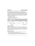
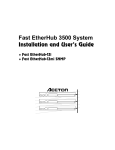
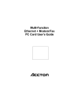
Fast EtherHub-12s &INO<GG<ODJI*<IP<G Installation Manual Fast EtherHub-12s Smart Fast Ethernet Hub with 12 100BASE-TX Ports Copyright (c) 1997 by Accton Technology Corporation. All rights reserved. No part of this document may be copied or reproduced in any form or by any means without the prior written consent of Accton Technology Corporation. Accton makes no warranties with respect to this documentation and disclaims any implied warranties of merchantability, quality, or fitness for any particular purpose. The information in this document is subject to change without notice. Accton reserves the right to make revisions to this publication without obligation to notify any person or entity of any such changes. Before operating this product, please review the statements on electomagnetic emission interference and safety compliance in Appendix D. ,QWHUQDWLRQDO+HDGTXDUWHUV 86$+HDGTXDUWHUV No. 1 Creation Road III, Science-based Industrial Park Hsinchu 300, Taiwan, R.O.C. Phone: 886-3-5770-270 FAX: 886-3-5770-267 BBS: 886-3-5770-654 Internet: [email protected] 1962 Zanker Road San Jose, CA 95112 Phone: 408-452-8900 FAX: 408-452-8988 BBS: 408-452-8828 FAST FAX: 408-452-8811 Accton, EtherHub and SmartWatch are trademarks or registered trademarks of Accton Technology Corporation. Other trademarks or brand names mentioned herein are trademarks or registered trademarks of their respective companies. EH3012-TX 150114-101 E0197-R02 Package Contents Carefully unpack the contents of the package and verify them against the checklist given below. Package Checklist æ æ æ æ æ Fast EtherHub-12s (Model No. EH3012-TX) AC power cord (optional) Four rubber foot pads Installation manual Warranty registration card Please inform your dealer immediately should there be any wrong, missing, or damaged parts. If possible, retain the carton, including the original packing materials. Use them again to repack the unit in case there is a need to return it for repair. To qualify for product updates and product warranty registration, fill in the Owner Registration Card and return it to Accton Technology Corporation. Package Contents i Quick Installation The Fast EtherHub-12s is a Class II repeater. It contains 12 100BASE-TX Fast Ethernet ports. The smart design built into the front display panel provides a friendly interface that simplifies installation and network troubleshooting. If you are already familiar with basic network operations, you should be able to install this hub as described below: 1. Unpack the Fast EtherHub-12s. 2. Find a location close to the network devices you need to connect, and within easy reach of an electrical outlet. 3. Mount the hub on a desktop or any other flat surface. If you are installing multiple hubs, you can stack them on top of each other (after attaching the foot pads), or install them in an standard EIA 19-inch rack. 4. Connect any devices that use a standard network interface to the RJ-45 (MDI-X) station ports (e.g., a workstation, server or router). Use 100 W Category 5 STP or UTP cable to connect to the hub, and be sure the length of any twisted-pair connection does not exceed 100 meters. Refer to Chapter 3 for sample configurations. To cascade to another hub or switch, run straight-through twisted-pair cable from the (12MDI) daisy-chain port on this hub to any (MDI-X) station port on the other device (or vice versa). Refer to Figure 3.2. If necessary, you can also cascade between two station ports using crossover cable. However, be sure not to exceed the maximum length between end nodes. Assuming that the maximum cable length is used for end-node connections (i.e., 100 meters), then the inter-hub cabling should be limited to 5 meters. However, if you need to extend this length of inter-hub cabling beyond 5 meters, then Quick Installation iii Fast EtherHub-12s User’s Guide first calculate the maximum length permitted between each pair of end nodes as described in Chapter 2 under the section on Precise Cable Length Budgeting. 5. Verify network communications by ensuring that • you have made all the necessary connections • you can access any connected resources • the hub’s indicators are functioning properly If you encounter any problems in installing the Fast EtherHub, refer to Chapter 2 for a detailed description of installation procedures, Chapter 3 for sample configurations, or Appendix A for help in troubleshooting. Note: Refer to Chapter 2 for a more detailed description of calculating the maximum cable length permitted between two end nodes for Fast Ethernet. iv Quick Installation About this Guide This guide is designed for the experienced network installer. It describes how to install and operate Accton’s Fast EtherHub-12s. After reading this manual, you should be able to use the front display panel and configure options to manage all your network connections. This manual covers the following topics: Chapter 1 - Product Overview Brief description of Fast Ethernet, followed by a description of this hub and a summary of its important features and specifications. Chapter 2 - Installing the System Installing a Fast EtherHub and making basic network connections. Chapter 3 - Configuring the Network Shows sample network configurations for a local area network. Chapter 4 - Hardware Reference Detailed description of indicator panel and ports. Appendices Troubleshooting, cable assignments, and product specifications. About this Guide v Contents Chapter 1: Product Overview ................................................. 1-1 Introduction to Fast Ethernet .....................................................................................1-1 Accton’s Fast EtherHub-12s......................................................................................1-1 Basic Features ...........................................................................................................1-2 Chapter 2: Installing the System............................................ 2-1 Pre-Installation Requirements ...................................................................................2-1 Connecting the Hub System ......................................................................................2-2 Making a Connection via an MDI-X Station Port ................................................2-2 Making a Connection via the MDI Daisy-Chain Port...........................................2-3 Simplified Cable Length Constraints ..............................................................2-4 Precise Cable Length Budgeting.....................................................................2-4 Providing Power to the EtherHub..............................................................................2-5 Verifying Port Status .................................................................................................2-6 Verifying System Operation......................................................................................2-6 Chapter 3: Configuring the Network...................................... 3-1 Stand-Alone...............................................................................................................3-1 Connecting Multiple Hubs ........................................................................................3-1 Using the RJ-45 Daisy-Chain Port........................................................................3-2 Precies Guidelines for Configuring Multiple Hubs ..............................................3-3 Chapter 4: Hardware Reference............................................. 4-1 Front Panel ...............................................................................................................4-1 Indicators ..............................................................................................................4-1 Fan Alert .........................................................................................................4-2 Power Status ...................................................................................................4-2 Statistical Display for System Performance....................................................4-3 Port Status Display..........................................................................................4-4 RJ-45 Ethernet Ports.............................................................................................4-5 Rear Panel ...............................................................................................................4-6 Power Socket........................................................................................................4-6 Contents vii Fast EtherHub-12s User’s Guide Appendix A: Troubleshooting................................................ A-1 Diagnosing Hub Indicators........................................................................................A-1 System Diagnostics ...................................................................................................A-2 Power and Cooling Problems ...............................................................................A-2 Installation ............................................................................................................A-2 Physical Configuration .........................................................................................A-3 Hub Integrity ........................................................................................................A-3 Appendix B: Port and Cable Assignments............................. B-1 RJ-45 Port ...............................................................................................................B-1 Appendix C: Specifications.................................................... C-1 Product Specifications...............................................................................................C-1 Appendix D: Regulatory Standards Compliance.................. D-1 EMI Certification ......................................................................................................D-1 FCC Class B Certification ....................................................................................D-1 Voluntary Control Council for Interference (VCCI-2) .........................................D-2 European Community Immunity Requirements....................................................D-3 CE Mark Declaration of Conformance (for EMI and Safety)...............................D-3 Safety Compliance.....................................................................................................D-4 Underwriters Laboratories Inc..............................................................................D-4 Sicherheitshinweise ..............................................................................................D-5 Appendix E: Product Support Services ................................ E-1 Product Registration ..................................................................................................E-1 Problem Report .........................................................................................................E-1 Hardware Repair Service...........................................................................................E-1 Bulletin Board Service (BBS) ...................................................................................E-2 Interactive Fast Fax (U.S.A. office) ..........................................................................E-2 Technical Support .....................................................................................................E-3 viii Contents Fast EtherHub-12s User’s Guide Limited Warranty .......................................................................................................E-4 Customer Remedies..............................................................................................E-4 Return Process......................................................................................................E-5 Accton Offices...........................................................................................................E-6 Ordering Information ................................................................................................E-6 Glossary Index List of Figures Figure 3.1 Figure 3.2 Figure 3.3 Figure 4.1 Figure 4.2 Figure 4.3 Figure B-1 Stand-Alone Configuration ....................................................................3-1 Multiple Hub Configuration Using the Daisy-Chain Port ......................3-2 Cabling Limits for Multiple Hub Configuration.....................................3-4 Front Panel .............................................................................................4-1 Indicators ...............................................................................................4-2 Rear Panel ..............................................................................................4-6 RJ-45 Connector (on the Hub Side) .......................................................B-1 List of Tables Table B-1 RJ-45 Pin Assignments............................................................................B-1 Contents ix Chapter 1: Product Overview Introduction to Fast Ethernet Standard 10 Mbps Ethernet has served well for past generations of 286 and 386 machines performing simple file transfers. However, with the inevitable growth in corporate network size and the introduction of fully-functional 32-bit PC architectures, and operating systems running complex applications, 10 Mbps Ethernet has become a serious bottleneck. With the recent flood of choices for upgrading media bandwidth, 100 Mbps Fast Ethernet has become the most popular choice because of its low cost, compatibility with existing Ethernet applications, and the fact that it can run on top of an installed base of twisted-pair cabling. Fast Ethernet can be easily integrated into an existing 10 Mbps Ethernet environment with no need for protocol translation or changes to network software. Accton’s Fast EtherHub-12s The Fast EtherHub-12s includes 12 100BASE-TX Ethernet ports. It provides a friendly design that simplifies installation and network troubleshooting. The SmartWatchTM indicator panel includes Utilization and Collision rate LEDs, as well as Partition, Link and Traffic LEDs to ease network management. The Fast EtherHub-12s can be used to relieve common network congestion, regardless of whether it is caused by too many stations contending for limited bandwidth or by a server that is supporting too many users. It can significantly improve access both to key servers and to the network backbone. This hub not only delivers a vast improvement in network response time, but helps you maintain outstanding performance as your user community continues to grow. Product Overview 1-1 Fast EtherHub-12s User’s Guide Basic Features • Transmits data at 100 Mbps for demanding applications • Conforms to the IEEE 802.3u repeater specification for 100BASE-TX • Provides 12 RJ-45 100BASE-TX station ports (using MDI-X wiring) • Port 12 can serve as an MDI-X station port (for connection to network devices such as workstations or servers) or as an MDI daisy-chain port (for connection to network devices such as hubs or switches), eliminating the need for crossover cables • Supports 100Ω Category 5 shielded or unshielded cable (STP or UTP) • Friendly design that monitors network utilization, collisions, link and port partition status • LED indicator panel including Utilization and Collision rate indicators for reporting hub activity and facilitating problem diagnosis • Automatically partitions bad ports to protect the network system • Automatic polarity detection and correction permits automatic adjustment for wiring errors • Plug-and-play operation • An Alert LED that shows if the fan has failed The Fast EtherHub-12s also supports the following basic system safeguards: • This hub features automatic partitioning and reconnection, jabber lockup protection, and automatic polarity detection for network cabling. 1-2 Product Overview Fast EtherHub-12s User’s Guide • With automatic partitioning and reconnection, any port is automatically isolated if excessive collisions occur on it. When the condition is corrected, the port is automatically reconnected. • With the jabber lock-up function, the hub automatically stops transmission of abnormal Ethernet frames that may cause data loss for all network users. (Jabber refers to abnormal Ethernet frames which are much too long and may come from a malfunctioning Ethernet card.) • With automatic polarity detection, the hub recognizes and adjusts for attached cable assemblies which may be wired with incorrect polarity on the receive pair. Product Overview 1-3 Chapter 2: Installing the System This chapter provides information on installing the Fast EtherHub-12s, establishing network connections, and configuring the system. You may install this hub on any level surface (e.g., a table or shelf) or in a standard EIA equipment rack. However, please take note of the following minimum site requirements before you begin. Pre-Installation Requirements Before you start actual hardware installation, make sure you can provide the right operating environment, including power requirements, sufficient physical space, and proximity to other network devices that are to be connected. Verify the following installation requirements: • Power requirements: 100 to 240 VAC (± 10%) at 50 to 60 Hz (± 3Hz). The hub’s power supply automatically adjusts to the input voltage level. • The EtherHub should be located in a cool dry place, with at least 10 cm. of space at the front and back for ventilation. • Place the hub out of direct sunlight, and away from heat sources or areas with a high amount of electromagnetic interference. • Check if network cables and connectors needed for installation are available. • Find a suitable location at the center of the devices you want to link, and near a power outlet Installing the System 2-1 Fast EtherHub-12s User’s Guide Connecting the Hub System This hub is a Fast Ethernet repeater for 100BASE-TX networks. The EtherHub-12s has 12 RJ-45 station ports, of which Port 12 can serve as either a station port or a daisy-chain port (depending on the port’s switch setting). The station ports allow you to make connections to devices such as a workstation, server or router. You can also cascade to another compatible hub or switch by connecting an MDI port on one device (e.g., port 12MDI on this hub) to an MDI-X port on the other device. Or you can cascade from an MDI port on another device to any MDI-X port on this hub. See Figure 4.1. Making a Connection via an MDI-X Station Port You can connect an RJ-45 station port on the hub to any device that uses a standard network interface such as a workstation or server, or also to a network interconnection device such as a router (depending on the port type implemented). 1. Prepare the network devices you wish to network. Make sure you have installed suitable 100BASE-TX network interface cards for making a connection to any of the hub’s station ports. You also need to prepare straight-through shielded or unshielded twisted-pair cables with RJ-45 plugs at both ends. Use 100W Category 5 cable for all connections. 2. Connect one end of the cable to the RJ-45 port of the network interface card (or comparable port type) on the device you are attaching to the hub, and the other end to any available (MDI-X) station port on the hub. When inserting an RJ-45 plug, be sure the tab on the plug clicks into position to ensure that it is properly seated. Using the hub in a stand-alone configuration, you can network up to 12 nodes. I Do not plug a phone jack connector into the RJ-45 port. This may damage the hub. Use only twisted-pair cables with RJ-45 connectors that conform with FCC standards. Notes: 1. When connecting to station Port 12, set the port selection switch to MDI-X. 2. Make sure each twisted-pair cable does not exceed 100 meters. 2-2 Installing the System Fast EtherHub-12s User’s Guide Making a Connection via the MDI Daisy-Chain Port 1. To make a direct connection to another compatible repeater or switch, use the 12MDI daisy-chain port. When connecting to this port, remember to set the port selection switch MDI. 2. Prepare straight-through shielded or unshielded twisted-pair cables with RJ-45 plugs at both ends. Use 100W Category 5 cable for all connections. Connect one end of the cable to Port 12MDI on this hub, and the other end to a standard MDI-X station port on the other device. When inserting an RJ-45 plug, be sure the tab on the plug clicks into position to ensure that it is properly seated. Notes: 1. When connecting to Port 12MDI, set the port selection switch to MDI. 2. Make sure the length of twisted-pair cable does not exceed 100 meters. 3. To connect to another hub or switch, you may also run straight-through twisted-pair cabling from a station port on this hub to a crossover port on another device. However, if you must connect to another device via station ports at both ends of the cable, use crossover cabling. Distance Limit for Fast Ethernet Cabling There are two common ways to calculate maximum cable length. The first way, which is refered to as the “Simplified Cable Length Constraints” method assumes that the maximum permissible cable length is used to connect various end-node devices (such as workstations or servers) to the hub. A more careful method of calculating maximum cable length, referred to as the “Precise Length Budgeting” method, requires you to measure the exact cable length for each pair of nodes that need to communicate, and to provide the signal delay time for each hub in your system. Both of these methods are described in this section. Installing the System 2-3 Fast EtherHub-12s User’s Guide Simplified Cable Length Constraints The Fast EtherHub-12s is a Class II repeater. IEEE recommends that Class II hubs be limited to a cascade of two hubs. The simplest rule is that workstation connections be limited to 100 meters for twisted-pair cabling, and that interhub cabling be limited to 5 meters. If you are stacking hubs in a wiring closet, this is good advise. When a hub is located in central wiring closet, connections to end users tend to be very long. Using these assumptions, then maximum cable lengths depend on the device type you want to attach to the hub, as shown in the following table: cable type twisted-pair workstation 100 meters another hub 5 meters switch 100 meters When connecting to another hub, traffic is confined to a single collision domain. However, when connecting to a collapsed backbone (e.g., a switch or router), the collision domain is broken up, enabling the use of longer cable lengths as illustrated in the preceeding table. Precise Cable Length Budgeting If you plan on installing a network for a small office, it may not be convenient to place hubs within 5 meters of each other, and then run up to 100 meters of cabling for each end user. This kind of installation can be very messy and wastes a lot of cabling. Depending on how your users are spread out, it may be more convenient to run a longer length of inter-hub cabling (say 50 meters or more), and then run shorter lengths of cable from each hub to the end users. Depending on the inherent delay in the hub and the maximum cable lengths required, it may even be possible to cascade up to three Fast Ethernet hubs. However, when setting up these kinds of distributed cascades, you have to be very careful in calculating the maximum length for each node pair. All endnode devices (e.g., workstations or servers) must be within 100 meters of the 2-4 Installing the System Fast EtherHub-12s User’s Guide connected hub when using twisted-pair cabling. However, when linking one or more Fast Ethernet repeaters together (i.e., in the same collision domain), the overall length of cable used between any two nodes should not exceed the limits outlined in the IEEE 802.3u standard. In precise terms, the maximum length of cabling that can be run from end-node to end-node is 367m ≥ S(repeater equivalent length) + S(length of CAT-5 twisted-pair cable) This 100BASE-TX Class II device has an inherent repeater delay of 90 bit time or 80 meters of twisted-pair cable. Taking a daisy chain of two hubs connected via twisted-pair cabling for an example, the maximum length from node to node is 367m - (2 x 80m) = 207m. Therefore, if both node A and B are linked to separate repeaters in a two hub system, each using 100 meters of cable to connect to their respective hub, then the inter-hub cabling will be limited to 5 meters (i.e., 207m - 2x100m = 7m, which is then reduced to 5 meters according to a common wiring rule). Providing Power to the EtherHub 1. Power on the hub by plugging the power cord into the power socket at the rear of the EtherHub (see Figure 4-2), and the other end into a power outlet. 2. Check the LED marked Power on the front panel to see if it is on. The unit will automatically select the setting that matches the connected input voltage. Therefore, no additional adjustments are necessary when connecting it to any input voltage within the range marked on the rear panel. F The unit supports a “hot remove” feature which permits you to connect/ disconnect cables without powering off the hub and without disrupting the operation of attached devices. Installing the System 2-5 Fast EtherHub-12s User’s Guide Verifying Port Status Check each connection by viewing the port status indicators listed below. (For a more detailed description of these indicators, refer to Chapter 4.) Indicates that the port has established a valid network connection. Traffic Indicates traffic traversing the port. Partition Indicates that the port has been isolated from the hub due to excessive errors. If the Link status indicator is not functioning properly, or you experience any other difficulties in setting up the hub, refer to Appendix A. Link Verifying System Operation Verify that all attached devices have a valid connection. The hub monitors link status for each port. If any device is properly connected to the hub and transmitting a link beat signal, the Link indicator lights up for the corresponding port. If the Link indicator fails to light up when you connect a device to the hub, check the following items: • Be sure the twisted-pair cable is properly attached to the connected device and the hub. Verify that the RJ-45 plug snaps into place when attached. • See if the twisted-pair cable is functioning properly by using it for another port and attached device that already displays valid indications when connected to the network. • Check the length of the twisted-pair connection to be sure it does not exceed 100 meters. If you are using bit budget calculations to determine maximum cable lengths, then be sure you have not exceeded the maximum cable length calculated for any potential node pair. 2-6 Installing the System Fast EtherHub-12s User’s Guide • Test the adapter for an attached workstation by trying it in another computer that has been successfully connected to the network. If you still can’t resolve the problem, please refer to Troubleshooting in Appendix A. Installing the System 2-7 Chapter 3: Configuring the Network The Fast EtherHub-12s allows great flexibility in configuring your network. You can use it in a stand-alone or multiple hub configuration. Some of the common applications for this Fast EtherHub are described in this chapter. Stand-Alone This hub can be used in a simple stand-alone configuration as illustrated below. In compliance with IEEE 802.3u standards, the maximum cable distance between the hub and any workstation is 100 meters for twisted-pair cable. Figure 3-1 Stand-Alone Configuration Connecting Multiple Hubs In a multiple hub configuration, the maximum overall segment length for interhub cabling depends on many factors, including the length of the cables used to connect station nodes to the hub system and the number of hubs you cascade together. You can use simple calculations to determine the maximum network diameter or the stricter guidelines outlined by IEEE 802.3u standard. Configuring the Network 3-1 Fast EtherHub-12s User’s Guide Using the RJ-45 Daisy-Chain Port You can easily connect to another hub via the MDI daisy-chain port (Port 12). When using Simplied Cable Length Constraints as described in Chapter 2, the interhub cable length is 5 meters. Figure 3-2 shows a sample configuration. Figure 3-2 Multiple Hub Configuration Using the Daisy-Chain Port 3-2 Configuring the Network Fast EtherHub-12s User’s Guide Precise Guidelines for Configuring Multiple Hubs A detailed formula for calculating maximum cable length was provided in the section on Precise Cable Length Budgeting in Chapter 2. This formula stated that the maximum length of cabling that can be run from end-node to end-node is: 367m ≥ S(repeater equivalent length) + S(length of CAT-5 twisted-pair cable) For the daisy chain of three hubs shown in Figure 3-3, communications must be supported for node pairs AB and AC. In this case, first determine the limitations on cable length found on the longest path (i.e., the path with the longest delay time). Remember that this Class II device has an inherent repeater delay of 90 bit time or 80 meters of twisted-pair cable. Therefore, if node A and B are linked to repeaters 1 and 3 respectively (each using 50 meters of twisted-pair cable), then the maximum length from node A to B is 367m - (3 x 80m) = 127m and the total inter-hub cabling will be limited to 27 meters (i.e., 127m - 2x50m = 27m). Therefore, if you use 15 meters of twisted-pair cable to connect hubs 1 and 2, then 12 meters of cable can be used to connect hubs 2 and 3. Then, if node A and C are linked to adjacent repeaters 1 and 2 in this system, the maximum length of twisted-pair cable that can be used to connect node C to hub 2 is 367m - 2*80m - 50m - 15m = 142 meters. However, the maximum length for any twisted-pair connection cannot exceed 100 meters. Configuring the Network 3-3 Fast EtherHub-12s User’s Guide Figure 3-3 Cabling Limits for Multiple Hub Configuration Notes: 1. The maximum length for each cable must be determined by calculations for the longest path (i.e., node-to-node connection) that passes through that segment. 2. To control the number of hubs in a path, we recommend that one hub be used to connect to several other hubs. Make sure there is only one path between any two stations on the network. 3. If you need to connect network devices over a long distance, use a switching hub or router to split the network up into two or more collision domains. For detailed information on purchasing the required equipment, contact your local distributor or Accton representative for support. 3-4 Configuring the Network Chapter 4: Hardware Reference Before connecting any network device to this hub, please review Chapter 2 for information on system installation and Chapter 3 for a brief look at common network architectures. This chapter describes the hardware features of the Fast EtherHub-12s. For easier management and control of the hub, familiarize yourself with the display indicators and ports. Front Panel There are 12 RJ-45 MDI-X station ports and 1 RJ-45 MDI daisy-chain port on the front panel. Moreover, the system indicators provide a simple interface for monitoring the hub. The front panel includes an alert indicator to show if the fan has failed, a power indicator, a statistical display for network traffic, and port status indicators as shown below. 100BASE-TX Class II Repeater Figure 4.1 Front Panel Indicators The SmartWatch indicator panel simplifies monitoring of various network conditions by providing LEDs that indicate the status of each station port and the overall condition of the hub. It provides all the key information required to manage your network on a daily basis. The following pages list the indicators and their functions. Hardware Reference 4-1 Fast EtherHub-12s User’s Guide The front panel array provides indicators that show the utilization of network bandwidth and indicate the status of port connections. It includes port status indicators and a statistical display for network traffic as shown below. Figure 4.2 Indicators Fan Alert Color: Label: Function: Condition ON OFF Red Alert Fan status Indication The unit’s fan has failed. (Call for service) The unit’s fan is functioning properly. Power Status Color: Label: Function: Condition ON OFF 4-2 Green Power Power indicator Indication Unit is receiving power. Power is disconnected, no power received. Hardware Reference Fast EtherHub-12s User’s Guide Statistical Display for System Performance Utilization - (Utilization%) The statistical indicators show the percentage of valid data passing through all ports compared to overall network bandwidth (updated every 0.5 seconds). There are 5 LEDs representing the percentage of network utilization. The corresponding LEDs light up to show that the utilization of LAN bandwidth has reached this level. When active, these LEDs behave like a stereo’s equalizer display. For example, if network utilization reaches 1%, the LED labeled 1% will light up. However, if network utilization rises above 1% (e.g., 30%), the LED labeled 30 and all the other LEDs before it (i.e., 1, 5 and 15) will also light up in rapid succession. These indicators monitor the share of valid network frames handled by the hub within a 100 Mbps bandwidth. They provide a quick way to monitor the current traffic load relative to the network’s capacity. Collision - (Collision%)- The statistical indicators show the percentage of packet collisions occurring out of the total packets transmitted by the hub. Collisions occur when two or more devices connected to a hub attempt to transmit data simultaneously on the network. When a collision occurs, devices pause and then re-transmit after a pseudo-random wait period. Because wait periods differ among devices, successive collisions become increasingly improbable. The Collision LEDs assist the network manager in monitoring the percentage of packet collisions occurring relative to the total packets transmitted by the hub. When collisions reach a level marked on the front panel display, the corresponding LED lights up. For example, if packet collisions reach 1%, the LED labeled 1% will light up. However, if collisions go beyond 1% (e.g., 15%), the LED labeled 15+% and all the other LEDs before it (i.e., 1, 3, 5 and 10) also light up in rapid succession. Hardware Reference 4-3 Fast EtherHub-12s User’s Guide Note: If the hub displays a high collision rate, check to see if any of the connected devices are malfunctioning or if a loop has been formed in your network connections. Otherwise, you may need to reconfigure your network to balance the traffic load. Port Status Display Partition Status Color: Label: Function: Condition ON OFF Red Partition Shows if the port has been isolated from the network Indication Indicates port has been partitioned due to an abnormal network condition. Port is in good condition. A port is temporarily partitioned when a line error or too many collisions are detected on the attached segment. While it is automatically partitioned, the port continues to receive data from the segment. However, data is not transmitted onto the segment. When the problem is corrected or a valid data packet is received through the port, the port is automatically reconnected. When partitioning occurs, the port’s corresponding Partition LED will be continually lit (RED light). Otherwise, this LED should be OFF (unlit). Notes: 1. When a long run of collisions occur on the cable connected to a hub port (i.e., 64 collisions), that port is automatically partitioned by the hub. It is automatically reconnected when a collision-free data packet at least 512 bits long (i.e., a minimum size legal packet) passes through the port. Link Status Color: Label: Function: Condition ON OFF 4-4 Green Link Indicates a valid network connection associated with the port. Indication Indicates a valid link has been established on this port. No valid link has been established on this port. Hardware Reference Fast EtherHub-12s User’s Guide Troubleshooting: If the Link LED does not light up when a device is connected to its corresponding port, check that both the hub and connected device are powered on. Be sure the cable length for all devices connected to the hub are within the limits described under Distance Limit for Fast Ethernet Cabling in Chapter 2. As a general rule, be sure that none of your twisted-pair cables exceed 100 meters. You should have standard, straightthrough cables and not crossover or other specialized cables. Incoming Traffic Color: Label: Function: Condition BLINKING OFF Green Traffic Indicates traffic entering the port. Indication Indicates the port is receiving packets; blinking is proportional to the traffic entering the port. No packets are being received by this port. RJ-45 Ethernet Ports This hub includes 12 Fast Ethernet station ports; of which Port 12 can also serve as a daisy-chain port. Use straight-through twisted-pair cable to connect the shielded MDI-X station ports to a workstation or server; or to connect the MDI port to another network interconnection device, such as a hub or switch. When using Port 12, remember to set the selection switch to MDI-X when connecting to a workstation, or to MDI when cascading to another hub or switch. Remember to use 100Wcategory 5 straight-through twisted-pair cable (STP or UTP) for all standard connections. Note: If you must cascade between MDI-X station ports on two hubs, then use crossover cable. Hardware Reference 4-5 Fast EtherHub-12s User’s Guide Rear Panel The rear panel on the hub includes a full-range power socket. Figure 4.3 Rear Panel Power Socket The power socket accepts AC power from 100 to 240V at 50 to 60Hz. The unit is equipped with a universal full-range power source. 4-6 Hardware Reference Appendix A: Troubleshooting Diagnosing Hub Indicators This Fast EtherHub can be easily monitored through its comprehensive panel indicators. These indicators assist the network manager in identifying problems the hub may encounter. This section describes common problems you may encounter and possible solutions. Symptom: Power indicator does not light up. Cause: Defective power outlet, power cord, or internal power supply. Solution: Have your unit’s power supply or Power LED replaced. Ask for dealer assistance. Symptom: Partition indicator lights up. Cause: Hub has partitioned a port. Solution: If port partitioning has occurred, the hub will automatically enable the port when the faulty condition disappears. Symptom: Link/Traffic indicator remains unlit after making a connection. Cause: Workstation’s network adapter, the cable, or the hub port is defective. Solution: Verify that the hub and attached device are powered on. Be sure the cable is plugged into both the hub and corresponding device. Verify that the proper cable type is used (Chapter 2), and that its length does not exceed 100 meters. Check the adapter on the attached device and cable connections for possible defects. Replace the defective adapter or cable if necessary Use the diagnostic procedures described in the following section to verify that all other system components are functioning properly. If you still cannot resolve the problem, contact your Accton distributor for assistance. Troubleshooting A-1 Fast EtherHub-12s User’s Guide System Diagnostics Power and Cooling Problems If the Power indicator does not turn on when the power cord is plugged in, you may have a problem with the power outlet, power cord, or internal power supply as explained in the previous section. However, if the unit powers off after running for a while, check for loose power connections, power losses or surges at the power outlet, and verify that the fan on back of the unit is unobstructed and running prior to shutdown. If you still cannot isolate the problem, then the internal power supply may be defective. In this case, contact your Accton distributor for assistance. Installation Verify that all system components have been properly installed. If one or more components appear to be malfunctioning (e.g., the power cord or network cabling), test them in an alternate environment where you are sure that all the other components are functioning properly. Cabling 1. Verify that the cabling type is correct. Be sure all cable connectors are securely seated in the required ports. Use 100 W Category 5 straight-through cable for all standard twisted-pair connections. 2. Make sure all devices are connected to the network. Equipment may have been unintentionally disconnected from the network. 3. When cascading two devices using RJ-45 station ports at both ends of the cable (i.e., not the MDI port), make sure a crossover cable is used. Crossover cable should only be used if a daisy-chain port is not available. A-2 Troubleshooting Fast EtherHub-12s User’s Guide External Adapters Make sure the network interface hardware and software drivers for the attached devices are function properly. Check the adapter cards and associated drivers used in any attached workstation or server. Physical Configuration If problems occur after altering the network configuration, restore the original connections, then try to track the problem down by implementing the new changes, one step at a time. Ensure that cable distances and other physical aspects of the installation do not exceed recommendations. Hub Integrity As a last resort verify the hub’s integrity with a power-on reset. Turn the power to the hub off and then on a few times. If the problem still persists and you have completed all the preceding diagnoses, contact your Accton distributor for further assistance. (Refer to Appendix E.) Troubleshooting A-3 Appendix B: Port and Cable Assignments RJ-45 Port Figure B-1 RJ-45 Connector (on the Hub Side) Pin 1 2 3 6 4,5,7,8 MDI-X Assignment (Station Port 1 ~ 12) Input Receive Data + Input Receive Data Output Transmit Data + Output Transmit Data Not Used MDI Assignment (Cascade Port 12) Output Transmit Data + Output Transmit Data Input Receive Data + Input Receive Data Not Used Table B-1 RJ-45 Pin Assignments Schematics for both straight and crossover twisted-pair cable are shown below. Straight-Through (Hub) 1 2 3 6 IRD+ IRDOTD+ OTD- (Adapter) 1 2 3 6 OTD+ OTDIRD+ IRD- Crossover (Hub) (Hub) 1 2 3 6 1 2 3 6 IRD+ IRDOTD+ OTD- Cable and Port Assignments IRD+ IRDOTD+ OTD- B-1 Appendix C: Product Specifications Transmission Technique Topology Access Method Standards Conformance Media Supported Interfaces Hub-to-Workstation Distance Daisy-Chain Distance (2 hubs) Dimensions Power Input Power Consumption Temperature Humidity Certification Emissions Immunity Safety Baseband Star or Tree CSMA/CD, 100Mbps IEEE 802.3u 100BASE-TX Class II Repeater Unshielded or shielded twisted-pair cable (100W Category 5 STP/UTP) 12 RJ-45 MDI-X station ports, Port 12 can be switched to function as an MDI-X station port or MDI daisy-chain port 100 meters maximum using category 5 STP or UTP cable 5 meters (assuming 100 meters from each node to hub) 440 mm x 192 mm x 43 mm (17.32"x 7.56" x 1.69") 100 to 240 VAC (10%), 50 to 60 Hz ( 3%) 2 Amp max. @ 100 VAC, 1 Amp @ 220 VAC 0°C to 40°C (Standard Operating) 5% to 95% (Noncondensing) CE Mark FCC Class B, VCCI Class 2, CISPR 22 Class B IEC 1000-4-2,3,4,6 UL, CSA, TÜV/GS Product Specifications C-1 Appendix D: Regulatory Standards Compliance EMI Certification FCC Class B Certification Accton Technology Corporation Model Numbers: EH3012-TX FCC ID: HED3012EHLCT-TX This device complies with Part 15 of the FCC Rules. Operation is subject to the following conditions: 1. This device may not cause harmful interference, and 2. This device must accept any interference received, including interference that may cause undesired operation. Warning! This equipment has been tested and found to comply with the limits for a Class B digital device, pursuant to Part 15 of the FCC Rules. These limits are designed to provide reasonable protection against harmful interference in a residential installation. This equipment generates, uses and can radiate radio frequency energy and, if not installed and used in accordance with the instructions, may cause harmful interference to radio communications. However, there is no guarantee that interference will not occur in a particular installation. If this equipment does cause harmful interference to radio or television reception, which can be determined by turning the equipment off and on, the user is encouraged to try to correct the interference by one or more of the following measures: • • • • Reorient or relocate the receiving antenna Increase the separation between the equipment and receiver Connect the equipment into an outlet on a circuit different from the one which the receiver is connected to Consult the dealer or an experienced radio/TV technician for help You are cautioned that changes or modifications not expressly approved by the party responsible for compliance could void your authority to operate the equipment. Regulatory Standards Compliance D-1 Fast EtherHub-12s User’s Guide Warnings 1. Wear an anti-static wrist strap or take other suitable measures to prevent electrostatic discharge whenever handling this equipment. 2. When connecting this hub to a power outlet, connect the field ground lead on the tri-pole power plug to a valid earth ground line to prevent electrical hazards. You may find the following booklet prepared by the Federal Communications Commission helpful: The Interference Handbook This booklet is available from the U.S. Government Printing Office. Washington, D.C. 20402. Stock No. 004-000-00345-4. Note: In order to maintain compliance with the limits of a Class B digital device, Accton requires that you use a quality interface cable when connecting to this device. Changes or modifications not expressly approved by Accton could void the user’s authority to operate this equipment. Suggested cable type is: • Twisted-pair for RJ-45 connections: 100WCategory 5 STP or UTP Voluntary Control Council for Interference (VCCI-2) This equipment is in the 2nd Class category and conforms to the standards set by the Voluntary Control Council for Interference by Data Processing Equipment and Electronic Office Machines aimed at preventing radio interference in residential areas. 2nd Class category equipment is qualified to be used in or near residential areas. However, if this equipment is placed near a functioning radio or telephone, data errors may result. D-2 Regulatory Standards Compliance Fast EtherHub-12s User’s Guide Read the instructions for correct handling. European Community Immunity Requirements This unit was tested and found to comply with the Class B limits of EN55022 (CISPR 22) and the immunity requirements of EN50082-1. CE Mark Declaration of Conformance (for EMI and Safety) This is to certify that this product complies with ISO/IEC Guide 22 and EN45014. It conforms to the following specifications: EMC: EN55022(1988)/CISPR-22(1985) IEC 1000-4-2(1995)/IEC 801-2(1991) IEC 1000-4-3(1995)/IEC 801-3(1984) IEC 1000-4-4(1995)/IEC 801-4(1988) IEC 1000-4-6(1995) class B 4kV CD, 8kV AD 3V/m 1kV - (power line), 0.5kV - (signal line) 3Vrms This product complies with the requirements of the Low Voltage Directive 73/23/EEC and the EMC Directive 89/336/EEC. Warning! Do not plug a phone jack connector in the RJ-45 port. This may damage the hub. Les raccordeurs ne sont pas utilisé pour le système téléphonique! Regulatory Standards Compliance D-3 Fast EtherHub-12s User’s Guide Safety Compliance Underwriters Laboratories Inc. Important! Before making connections, make sure you have the correct Cord Set. Check it (read the label on the cable) against the following specification list. Operating Voltage Cord Set Specifications 120 Volts 240 Volts (For North America) 240 Volts (For Europe only) UL Listed/CSA Certified Cord Set Minimum 18 AWG Type SVT or SJT three conductor cord Maximum length of 15 feet Parallel blade, grounding type attachment plug rated 15A, 125V UL Listed/CSA Certified Cord Set Minimum 18 AWG Type SVT or SJT three conductor cord Maximum length of 15 feet Tandem blade, grounding type attachment plug rated 15A, 125V Cord Set with H05VV-F cord having three conductors with minimum diameter of 0.75 mm2 IEC-320 receptacle Male plug rated 6A, 250V The unit will automatically select the setting that matches the input voltage connected. Therefore, no additional adjustments are necessary when connecting it to any input voltage within the range marked on the rear panel. D-4 Regulatory Standards Compliance Fast EtherHub-12s User’s Guide Sicherheitshinweise 1. Die Steckdose muß sich in der Nähe des Gerätes befinden und leicht zugänglich sein. 2. Zum Reinigen den Stecker aus der Steckdose ziehen. Beim Reinigen keine Flüssigreiniger oder Sprays verwenden, sondern ein angefeuchtetes Tuch. 3. Das produkt gerät nicht in Naßräume oder in der Nähe von Wasser benutzen, wie z.B. Badezimmer, Schwimmbad, Spülbecken usw.. Das Eindringen von Wasser kann zur Zerstörung des Gerätes führen. 4. Das produkt gerät nicht auf einer unstabilen Unterlage, wie z.B. Rollwagen, Gestell usw., aufstellen. Es könnte herunterfallen und Verletzungen oder Beschädigungen von Mensch und Gerät verursachen. 5. Die Belüftungsöffnungen nicht blockieren oder auf falscher Ober-fläche, wie Bett, Sofa usw., stellen. Durch die Blockierung kann es zur Zerstörung des Gerätes durch Überhitzung kommen. 6. Versuchen Sie niemals dieses Gerät selbst zu warten, da beim Öffnen oder Abnehmen des Gehäuses die Gefahr eines elektrischen Schlages besteht. 7. Keine Gegenstände auf das Anschlußkabel stellen, damit es nicht durch scharfe Kanten zerstört werden kann. 8. Keinerlei Gegenstände durch die Öffungen in das Gerät stecken, da es dadurch sonst zu Kurzschlässen kommen kann. 9. Bei Störungen des Gerätes den Wartungsdienst verständigen. 10. Bei Reperaturen dürfen nur Orginalersatzteile oder Bauteile mit gleichen Eigenschaften verwendet werden. Andere Bauteile können Feuer, elektrischen Schlag oder andere Gefahren verursachen. 11. Nach Beendigung von Wartungsarbeiten oder Reperaturen durch den Kundendienst sollte die Sicherheitsprüfung durchgeführt werden. 12. Bei längerem Stillstand des Gerätes, ist diese von der Versorgungs- spannung zu trennen. Dies verhindert eine Besch÷digung des Gerätes durch eine Überspannung in der Zuleitung. 13. Der arbeitsplatzbezogene Lärmschutzpegel nach DIN 45 635 ist kleiner 70dB (A). Regulatory Standards Compliance D-5 Appendix E: Product Support Services Product Registration Fill in the Owner Registration Card and mail it to Accton Technology Corporation. Accton will keep your record and inform you of any new Accton unit developments. Problem Report If problems occur during unit operation, please check the adapter configuration settings, cables, connectors, network terminators, hardware compatibility and other network components. Write a description of the problem, including what problems occurred, when they occurred, duration of the problems, the unit number, serial number, hardware, software and the DOS version that you are using. Then contact your dealer or Accton Technology Corporation for assistance. Hardware Repair Service You must get an RMA (Return Materials Authorization) number before returning any hardware for repair. To obtain this number please inform Accton of your company name, address, unit name and model number, contact person, telephone number, and a problem description list. If your unit is under repair warranty you must also give your purchase date. Carefully pack your hardware. If possible, use the original carton. Mark the RMA number on the carton and send it to your dealer. Product Support Services E-1 Fast EtherHub-12s User’s Guide After repair, Accton will inform you of the date of delivery and the exact amount due. Please send the payment by T/T (Telegram Transfer), and Accton will send you the fixed component after receiving payment. With or without warranty, if the hardware is found to be free of defects, you will only be charged for testing and handling. Bulletin Board Service (BBS) • In countries other than the U.S., call 886-3-5770-654 to reach Accton Taiwan’s modem line. Modems with 14400 through 2400 baud are supported. Choose 8 data bits, 1 stop bit and no parity. Standard VT100 terminal emulation is supported • In the United States, call 408-452-8828 to reach the Accton USA’s BBS line. Modems with 14400 through 2400 baud are supported. Choose 8 data bits, 1 stop bit and none parity. Standard VT100 terminal emulation is supported. Interactive Fast Fax (U.S.A. office) Printed technical documentation can be FAX’ed to your FAX machine, 24-hours a day. • Call 408-452-8811 to reach Accton’s interactive Fast FAX service. You will need a Touch-Tone phone and a FAX machine (or equivalent). Choose document 911 for a listing of technical bulletins. E-2 Product Support Services Fast EtherHub-12s User’s Guide Technical Support Your dealer or installer is the person who understands your network and Accton units. If neither is available to help you, Accton technical support engineers are available by FAX, mail or phone. • Send your technical questions by FAX to: International Headquarters: 886-3-5770-267 USA Headquarters: 408-452-8988 • To obtain software upgrades connect via ftp to ftp.accton.com.tw • Send your technical questions by email to [email protected] • Mail your technical questions to: International Headquarters Accton Technology Corporation Attn: Technical Support No. 1 Creation Road III Science-based Industrial Park Hsinchu 300, Taiwan, R.O.C. USA Headquarters Accton Technology Corporation Attn: Technical Support 1962 Zanker Road, San Jose, CA 95112, U.S.A. During local business hours, call: International Headquarters (Monday through Friday, 8 am to 6 p.m.): 886-3-5770-270 USA Headquarters (Monday through Friday, 7 am to 5 p.m. Pacific Time): 408-452-8900 or 800-926-9288 Product Support Services E-3 Fast EtherHub-12s User’s Guide Limited Warranty Accton warrants to the original owner that the product delivered in this package will be free from defects in material and workmanship for the lifetime of the product. For the warranty to apply, you must register your purchase by returning the registration card indicating the date of purchase and including proof of purchase. There will be a minimal charge to replace consumable components, such as fuses, power transformers, and mechanical cooling devices. The warranty does not cover the product if it is damaged in the process of being installed. Accton recommends that you have the company from whom you purchased this product install it. THE ABOVE WARRANTY IS IN LIEU OF ANY OTHER WARRANTY, WHETHER EXPRESS, IMPLIED OR STATUTORY, INCLUDING BUT NOT LIMITED TO ANY WARRANTY OF MERCHANTABILITY, FITNESS FOR A PARTICULAR PURPOSE, OR ANY WARRANTY ARISING OUT OF ANY PROPOSAL, SPECIFICATION OR SAMPLE. ACCTON SHALL NOT BE LIABLE FOR INCIDENTAL OR CONSEQUENTIAL DAMAGES. ACCTON NEITHER ASSUMES NOR AUTHORIZES ANY PERSON TO ASSUME FOR IT ANY OTHER LIABILITY. Customer Remedies If the product is found to be defective within the first two years from the later of date of purchase or date of manufacture, Accton’s entire liability and your exclusive remedy for any breach of warranty, shall be, at its option, to repair or replace the product at no charge except as set forth below. If the product is found to be defective after two years from the later of date of purchase or date of manufacture, Accton will charge a process and handling fee, provided that you deliver the product along with a return material authorization (RMA) number either to the company from whom you purchased it or to Accton. Accton warrants the repaired or replaced product to be free from defects in material and workmanship for the remainder of the original product’s warranty period. Consumable components are warranted only for two years. E-4 Product Support Services Fast EtherHub-12s User’s Guide Return Process Before you may return any Accton product to Accton, you must request an RMA number by calling, FAXing or writing Accton’s Service Department at the address listed below. If you ship the product, you must assume the risk of damage or loss in transit. You must use the original container (or the equivalent) and pay the shipping charge. Accton may replace or repair the product with either a new or reconditioned product, and the returned product becomes Accton’s property. At Accton’s sole discretion, Accton will issue a credit for either a comparable replacement Accton product or credit the original purchase price towards the purchase of any Accton product for any unrepairable, defective product. This warranty does not cover replacement of products damaged by abuse, accident, misuse, neglect, alteration, repair, disaster, improper installation or improper testing. ACCTON SHALL NOT BE HELD LIABLE FOR ANY LOSS OF PROFITS, LOSS OF USE, INCIDENTAL, CONSEQUENTIAL OR SPECIAL DAMAGES CAUSED BY THE USE OF THIS PRODUCT OR INABILITY TO USE IT, EVEN IF THE COMPANY OR ACCTON HAS BEEN ADVISED OF SUCH LIABILITY OR OTHER SPECIAL CLAIMS. If you purchased this product in the USA, be aware that some states do not allow limitations on how long an implied warranty lasts, so the above limitations may not apply to you. Some states do not allow the exclusion or limitation of incidental or consequential damages, so the above limitations or exclusions may not apply to you. This warranty gives you specific legal rights and you may have other rights which vary from state to state. All parts or components contained in this product are covered by Accton’s Limited Lifetime Warranty for this product. The product may contain fully tested, recycled parts, warranted as if new. For warranty information: All territories except North and South America: Accton Technology Corporation, International Headquarters No. 1, Creation Rd. III, Science-based Industrial Park, Hsinchu 300, Taiwan, R.O.C. Phone: 886-3-5770-270 Fax: 886-3-5770-267 BBS: 886-3-5770-654 North and South America: Accton Technology Corporation, USA Headquarters 1962 Zanker Road, San Jose, CA 95112, U.S.A. Phone: 408-452-8900 Fax: 408-452-8988 BBS: 408-452-8828 Product Support Services E-5 Fast EtherHub-12s User’s Guide Accton Offices Accton Australia, Level 6, 10 Help Street Chatswood, N.S.W. 2067 Australia Phone: 61-2-9410-9860 Fax: 61-2-9410-9861 BBS: 61-2-9410-9862 Internet: http://www.accton.com.au Accton Technology Corporation International Headquarters, No. 1 Creation Rd. III, Science-based Industrial Park, Hsinchu 300, Taiwan, R.O.C. Hsinchu: Phone: 886-3-5770-270, Fax: 886-3-5770-267, 886-3-5775-541 BBS: 886-3-5770-654 Taipei: Phone: 886-2-577-1220 to 9 Fax: 886-2-577-0816 Accton Japan, Kano Bldg. 7F, 1-25-1 Nishi-Gotanda, Shinagawa-ku, 141 Tokyo, Japan Phone: 81-3-3495-1351 Fax: 81-3-3495-1352 Accton USA, 1962 Zanker Road, San Jose, CA 95112, USA Phone: 408-452-8900, 408-452-8080 Fax: 408-452-8988 BBS: 408-452-8828 FAST FAX: 408-452-8811 Accton UK, The Mill Horton Road, Stanwell Moor, Staines. Middx. TW19 6BJ United Kingdom Phone: 44-1753-687677, 44-1753-680109 Fax: 44-1753-689010 Ordering Information • Fast EtherHub-8s (EH3042-TX) Fast Ethernet Hub with 8 100BASE-TX ports • Fast EtherHub-12s Fast Ethernet Hub with 12 100BASE-TX ports (EH3012-TX) • Fast EtherHub-12se (EH3012-TF-SC) or (EH3012-TF-ST) E-6 Fast Ethernet Hub with 12 100BASE-TX ports, and 1 100BASE-FX port (SC or ST type port) Product Support Services Glossary 100BASE-TX IEEE’s specifications for 100 Mbps Ethernet using twisted-pair cable (100W Cat. 5 STP or UTP). The maximum length of cable for a point-to-point connection is 100 meters. Collision A condition in which two packets transmitted over a medium interfere with each other. Their interference makes both signals unintelligible. The transmitting devices have to halt transmission for a random period of time before trying to send data again. Configuration The way to set up a computer, server, or local area network. Connection A logical binding between two or more users of an interconnection service. Daisy-Chain Port An MDI RJ-45 port used to cascade compatible devices in a daisy-chain configuration using straight-through twisted-pair cable. To cascade two devices, either run a connection from the daisy-chain port on one device to a station port on the other device, or cascade the two devices by running crossover cable between MDI-X station ports on both devices. Ethernet A network communication system developed and standardized by DEC, Intel, and Xerox, using baseband transmission, CSMA/CD access and logical bus topology, and coaxial cable. The successor IEEE 802.3 standard provides for integration into the OSI model and extends the physical layer and media with repeaters and implementations that operate on fiber optics, broadband, and twisted-pair. Glossary 1 Fast EtherHub-12s User’s Guide Fast Ethernet 100 Mbps network communication system based on Ethernet and the CSMA/CD access method. IEEE 802.3 Standard Standard for the physical and electrical connections in local area networks developed by the IEEE. The IEEE 802.3u standard covers these same issues for 100 Mbps networks. LED Light emitting diode on the front panel of the hub used for monitoring a hub or network condition. An LED display corresponds to a hub condition. Local Area Network (LAN) A group of interconnected computers and support devices. MDI Port (Medium Dependent Interface) MDI is the IEEE standard for the twisted-pair interface to 10BASE-T (or 100BASETX). This RJ-45 port can be used with straight-through cable to connect the hub to a network interconnection device, such as another hub or a switch. Pin-out assignments are shown in Appendix B. MDI-X Port (Medium Dependent Interface - Crossed) This RJ-45 port, which crosses the receive and transmit signals internally, can be used with straight-through cable to connect the hub to any device that has a standard network interface (e.g., workstation, server or router). Pin-out assignments are shown in Appendix B. RJ-45 Connector Most common terminator for twisted-pair wiring. 2 Glossary Fast EtherHub-12s User’s Guide Shielded Twisted-Pair (STP) 100W Category 5 twisted-pair wire covered with an external aluminum-foil or wovencopper shield designed to reduce excessive noise pick up or radiation. The STP cable refered to in this manual is also sometimes called screened twisted-pair (ScTP). Its impedance is 100Wand has the same pin assignment as UTP. This cable should not be confused with the older 150Wcable type designed by IBM. Star Topology Physical connections for this hub are limited to a star configuration (i.e., similar to a hub and spoke arrangement). This topology also requires that only one path exists between any two nodes, and that data transmitted by any node is concurrently available to all other nodes within the same local network (i.e., immediate collision domain). Station Port The MDI-X port can be used for connecting the hub to any device that has a standard network interface (e.g., workstation, server or router). For port 12, the selector switch must be set toMDI-X. (This port can also be connected to an MDI port on another compatible hub or a switch.) Unshielded Twisted-Pair (UTP) Cable composed of insulated wires twisted together to reduce electrical interference; used in common telephone cord. Glossary 3 Index Front Panel • 4-1 A G Accton's Fast EtherHub-12s • 1-1 Automatic Partitioning • 1-3 Automatic Polarity Detection • 1-3 Guidelines for Multiple Hub Configuration • 3-3 C H Cable Length Precise Cable Length Budgeting • 2-4 Simplified Cable Length Constraints • 2-4 Certification • C-1 Class II Repeater • 2-5, 3-3 Configuring the Network • 3-1 Connecting Multiple Hubs • 3-2 Connecting the Hub System • 2-2 Connection, Verifying • 2-6 Crossover Cable • B-1 Hardware Description • 4-1 D J Daisy-Chain Port Usage • 3-2 Distance Limit for Fast Ethernet Cabling • 2-3 Jabber Lock-up • 1-3 E LED Indicators Alert • 4-2 Collision% • 4-3 Link • 2-6, 4-4 Partition • 4-4 Power • 4-2 Traffic • 4-5 Utilization% • 4-3 Limited Warranty • E-4 EMI Certification • D-1 Ethernet Ports • 4-5 F Fast EtherHub-12s • 1-1 FCC Warning • D-1 Index I IEEE 802.3u Standard • 2-5, 3-1 Indicator Panel • 4-1 Installation Requirements • 2-1 Installing the System • 2-1 Inter-hub Cabling Limit • 3-3 Introduction to Fast Ethernet • 1-1 L 1 Fast EtherHub-12s User’s Guide Certification • C-1 Interfaces • C-1 Media Supported • C-1 Power System • C-1 Standards Conformance • C-1 Stand-alone Configuration • 3-1 Standards Compliance • D-1 M Maximum Cable Length • 2-4 MDI Daisy-chain Port • 3-2 N Network Connection MDI Daisy-Chain Port • 2-3 MDI-X Station Port • 2-2 T Troubleshooting • 4-5 Configuration • A-3 Hub Indicators • A-1 Installation • A-2 Power and Cooling • A-2 Twisted-pair Cable Category 3,4,5 • 2-2, A-2 P Port and Cable Assignments • B-1 Port Status Indicators • 4-4 Power Cord Specifications • D-4 Power Socket • 4-6 Product Features • 1-2 Product Support Services • E-1 Accton Offices • E-6 Bulletin Board Service • E-2 Hardware Repair Service • E-1 Interactive Fast Fax • E-2 Ordering Information • E-6 Technical Support • E-3 Providing Power to the Hub • 2-5 V Verifying Port Status • 2-6 Verifying System Operation • 2-6 R Rear Panel • 4-6 Repeater Delay • 2-5, 3-3 S Safety Compliance • D-4 Specifications 2 Index EH3012-TX 150114-101 E0197-R02