1
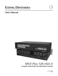
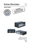
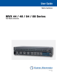
Setup
Setup Guide
Guide
Matrix Switchers
DXP DVI Pro
DXP HDMI
DVI and HDMI
Matrix Switchers
68-1370-50 Rev. C
03 12
Safety Instructions • English
Warning
This symbol is intended to alert the user of important
operating and maintenance (servicing) instructions in
the literature provided with the equipment.
Power sources • This equipment should be operated only from the power source indicated
on the product. This equipment is intended to be used with a main power system with a
grounded (neutral) conductor. The third (grounding) pin is a safety feature, do not attempt
to bypass or disable it.
This symbol is intended to alert the user of the presence
of uninsulated dangerous voltage within the product’s
enclosure that may present a risk of electric shock.
Power disconnection • To remove power from the equipment safely, remove all power cords
from the rear of the equipment, or the desktop power module (if detachable), or from the
power source receptacle (wall plug).
Caution
Read Instructions • Read and understand all safety and operating instructions
before using the equipment.
Retain Instructions • The safety instructions should be kept for future reference.
Follow Warnings • Follow all warnings and instructions marked on the
equipment or in the user information.
Avoid Attachments • Do not use tools or attachments that are not
recommended by the equipment manufacturer because they may be
hazardous.
Consignes de Sécurité • Français
Ce symbole sert à avertir l’utilisateur que la documentation fournie avec le matériel contient des instructions
importantes concernant l’exploitation et la maintenance (réparation).
Ce symbole sert à avertir l’utilisateur de la présence
dans le boîtier de l’appareil de  tensions dangereuses
non isolées posant des risques d’électrocution.
Attention
Lire les instructions• Prendre connaissance de toutes les consignes de sécurité
et d’exploitation avant d’utiliser le matériel.
Conserver les instructions• Ranger les consignes de sécurité afin de pouvoir
les consulter à l’avenir.
Respecter les avertissements • Observer tous les avertissements et consignes
marqués sur le matériel ou présentés dans la documentation utilisateur.
Eviter les pièces de fixation • Ne pas utiliser de pièces de fixation ni d’outils
non recommandés par le fabricant du matériel car cela risquerait de poser
certains dangers.
Sicherheitsanleitungen • Deutsch
Dieses Symbol soll dem Benutzer in der im Lieferumfang
enthaltenen Dokumentation besonders wichtige Hinweise
zur Bedienung und Wartung (Instandhaltung) geben.
Dieses Symbol soll den Benutzer darauf aufmerksam
machen, daß im Inneren des Gehäuses dieses Produktes
gefährliche Spannungen, die nicht isoliert sind und
die einen elektrischen Schock verursachen können,
herrschen.
Achtung
Lesen der Anleitungen • Bevor Sie das Gerät zum ersten Mal verwenden,
sollten Sie alle Sicherheits-und Bedienungsanleitungen genau durchlesen und
verstehen.
Aufbewahren der Anleitungen • Die Hinweise zur elektrischen Sicherheit
des Produktes sollten Sie aufbewahren, damit Sie im Bedarfsfall darauf
zurückgreifen können.
Befolgen der Warnhinweise • Befolgen Sie alle Warnhinweise und
Anleitungen auf dem Gerät oder in der Benutzerdokumentation.
Keine Zusatzgeräte • Verwenden Sie keine Werkzeuge oder Zusatzgeräte,
die nicht ausdrücklich vom Hersteller empfohlen wurden, da diese eine
Gefahrenquelle darstellen können.
Instrucciones de seguridad • Español
Este símbolo se utiliza para advertir al usuario sobre instrucciones importantes de operación y mantenimiento (o
cambio de partes) que se desean destacar en el contenido
de la documentación suministrada con los equipos.
Este símbolo se utiliza para advertir al usuario sobre la
presencia de elementos con voltaje peligroso sin protección aislante, que puedan encontrarse dentro de la caja
o alojamiento del producto, y que puedan representar
riesgo de electrocución.
Precaucion
Leer las instrucciones • Leer y analizar todas las instrucciones de operación y
seguridad, antes de usar el equipo.
Conservar las instrucciones • Conservar las instrucciones de seguridad para
futura consulta.
Obedecer las advertencias • Todas las advertencias e instrucciones marcadas
en el equipo o en la documentación del usuario, deben ser obedecidas.
Evitar el uso de accesorios • No usar herramientas o accesorios que no sean
especificamente recomendados por el fabricante, ya que podrian implicar riesgos.
Power cord protection • Power cords should be routed so that they are not likely to be
stepped on or pinched by items placed upon or against them.
Servicing • Refer all servicing to qualified service personnel. There are no user-serviceable
parts inside. To prevent the risk of shock, do not attempt to service this equipment yourself
because opening or removing covers may expose you to dangerous voltage or other hazards.
Slots and openings • If the equipment has slots or holes in the enclosure, these are provided
to prevent overheating of sensitive components inside. These openings must never be
blocked by other objects.
Lithium battery • There is a danger of explosion if battery is incorrectly replaced. Replace it
only with the same or equivalent type recommended by the manufacturer. Dispose of used
batteries according to the manufacturer’s instructions.
Avertissement
Alimentations • Ne faire fonctionner ce matériel qu’avec la source d’alimentation indiquée sur
l’appareil. Ce matériel doit être utilisé avec une alimentation principale comportant un fil de
terre (neutre). Le troisième contact (de mise à la terre) constitue un dispositif de sécurité :
n’essayez pas de la contourner ni de la désactiver.
Déconnexion de l’alimentation• Pour mettre le matériel hors tension sans danger,
déconnectez tous les cordons d’alimentation de l’arrière de l’appareil ou du module
d’alimentation de bureau (s’il est amovible) ou encore de la prise secteur.
Protection du cordon d’alimentation • Acheminer les cordons d’alimentation de manière
à ce que personne ne risque de marcher dessus et à ce qu’ils ne soient pas écrasés ou pincés
par des objets.
Réparation-maintenance • Faire exécuter toutes les interventions de réparation-maintenance
par un technicien qualifié. Aucun des éléments internes ne peut être réparé par l’utilisateur.
Afin d’éviter tout danger d’électrocution, l’utilisateur ne doit pas essayer de procéder luimême à ces opérations car l’ouverture ou le retrait des couvercles risquent de l’exposer à de
hautes tensions et autres dangers.
Fentes et orifices • Si le boîtier de l’appareil comporte des fentes ou des orifices, ceux-ci
servent à empêcher les composants internes sensibles de surchauffer. Ces ouvertures ne
doivent jamais être bloquées par des objets.
Lithium Batterie • Il a danger d’explosion s’ll y a remplacment incorrect de la batterie.
Remplacer uniquement avec une batterie du meme type ou d’un ype equivalent
recommande par le constructeur. Mettre au reut les batteries usagees conformement aux
instructions du fabricant.
Vorsicht
Stromquellen • Dieses Gerät sollte nur über die auf dem Produkt angegebene Stromquelle
betrieben werden. Dieses Gerät wurde für eine Verwendung mit einer Hauptstromleitung
mit einem geerdeten (neutralen) Leiter konzipiert. Der dritte Kontakt ist für einen
Erdanschluß, und stellt eine Sicherheitsfunktion dar. Diese sollte nicht umgangen oder außer
Betrieb gesetzt werden.
Stromunterbrechung • Um das Gerät auf sichere Weise vom Netz zu trennen, sollten Sie
alle Netzkabel aus der Rückseite des Gerätes, aus der externen Stomversorgung (falls dies
möglich ist) oder aus der Wandsteckdose ziehen.
Schutz des Netzkabels • Netzkabel sollten stets so verlegt werden, daß sie nicht im
Weg liegen und niemand darauf treten kann oder Objekte darauf- oder unmittelbar
dagegengestellt werden können.
Wartung • Alle Wartungsmaßnahmen sollten nur von qualifiziertem Servicepersonal
durchgeführt werden. Die internen Komponenten des Gerätes sind wartungsfrei. Zur
Vermeidung eines elektrischen Schocks versuchen Sie in keinem Fall, dieses Gerät selbst
öffnen, da beim Entfernen der Abdeckungen die Gefahr eines elektrischen Schlags und/oder
andere Gefahren bestehen.
Schlitze und Öffnungen • Wenn das Gerät Schlitze oder Löcher im Gehäuse aufweist,
dienen diese zur Vermeidung einer Überhitzung der empfindlichen Teile im Inneren. Diese
Öffnungen dürfen niemals von anderen Objekten blockiert werden.
Litium-Batterie • Explosionsgefahr, falls die Batterie nicht richtig ersetzt wird. Ersetzen Sie
verbrauchte Batterien nur durch den gleichen oder einen vergleichbaren Batterietyp, der
auch vom Hersteller empfohlen wird. Entsorgen Sie verbrauchte Batterien bitte gemäß den
Herstelleranweisungen.
Advertencia
Alimentación eléctrica • Este equipo debe conectarse únicamente a la fuente/tipo de
alimentación eléctrica indicada en el mismo. La alimentación eléctrica de este equipo debe
provenir de un sistema de distribución general con conductor neutro a tierra. La tercera pata
(puesta a tierra) es una medida de seguridad, no puentearia ni eliminaria.
Desconexión de alimentación eléctrica • Para desconectar con seguridad la acometida de
alimentación eléctrica al equipo, desenchufar todos los cables de alimentación en el panel
trasero del equipo, o desenchufar el módulo de alimentación (si fuera independiente), o
desenchufar el cable del receptáculo de la pared.
Protección del cables de alimentación • Los cables de alimentación eléctrica se deben
instalar en lugares donde no sean pisados ni apretados por objetos que se puedan apoyar
sobre ellos.
Reparaciones/mantenimiento • Solicitar siempre los servicios técnicos de personal
calificado. En el interior no hay partes a las que el usuario deba acceder. Para evitar riesgo de
electrocución, no intentar personalmente la reparación/mantenimiento de este equipo, ya
que al abrir o extraer las tapas puede quedar expuesto a voltajes peligrosos u otros riesgos.
Ranuras y aberturas • Si el equipo posee ranuras o orificios en su caja/alojamiento, es para
evitar el sobrecalientamiento de componentes internos sensibles. Estas aberturas nunca se
deben obstruir con otros objetos.
Batería de litio • Existe riesgo de explosión si esta batería se coloca en la posición incorrecta.
Cambiar esta batería únicamente con el mismo tipo (o su equivalente) recomendado por el
fabricante. Desachar las baterías usadas siguiendo las instrucciones del fabricante.
安全须知 • 中文
警告
这个符号提示用户该设备用户手册中
有重要的操作和维护说明。
电源 • 该 设 备 只 能 使 用 产 品 上 标 明 的 电 源 。 设 备
必须使用有地线的供电系统供电。 第三条线
(地线)是安全设施,不能不用或跳过。
这个符号警告用户该设备机壳内有暴
拔掉电源 • 为安全地从设备拔掉电源,请拔掉所有设备后
或桌面电源的电源线,或任何接到市电系统的电源线。
露的危险电压,有触电危险。
电源线保护 • 妥善布线, 避免被踩踏,或重物挤压。
注意
阅读说明书 • 用 户 使 用 该 设 备 前 必 须 阅 读 并 理
解所有安全和使用说明。
保存说明书 • 用户应保存安全说明书以备将来使
用。
遵守警告 • 用户应遵守产品和用户指南上的所有安
全和操作说明。
维护 • 所有维修必须由认证的维修人员进行。 设备内部
没有用户可以更换的零件。为避免出现触电危险不要自
己试图打开设备盖子维修该设备。
通风孔 • 有些设备机壳上有通风槽或孔,它们是用来防止
机内敏感元件过热。 不要用任何东西挡住通风孔。
锂电池 • 不正确的更换电池会有爆炸的危险。 必须使用
与厂家推荐的相同或相近型号的电池。 按照生产厂的
建议处理废弃电池。
避免追加 • 不要使用该产品厂商没有推荐的工具或
追加设备,以避免危险。
FCC Class A Notice
This equipment has been tested and found to comply with the limits for a Class A digital device,
pursuant to part 15 of the FCC Rules. Operation is subject to the following two conditions:
1. This device may not cause harmful interference.
2. This device must accept any interference received, including interference that may cause
undesired operation.
The Class A limits are designed to provide reasonable protection against harmful interference
when the equipment is operated in a commercial environment. This equipment generates, uses,
and can radiate radio frequency energy and, if not installed and used in accordance with the
instruction manual, may cause harmful interference to radio communications. Operation of this
equipment in a residential area is likely to cause harmful interference, in which case the user will
be required to correct the interference at his own expense.
NOTE:
This unit was tested with shielded cables on the peripheral devices. Shielded cables
must be used with the unit to ensure compliance with FCC emissions limits.
Conventions Used in this Guide
In this user guide, the following are used:
CAUTION:
NOTE:
TIP:
A caution indicates a potential hazard to equipment
or data.
A note draws attention to important information.
A tip provides a suggestion to make working with the
application easier.
WARNING:
A warning warns of things or actions that might
cause injury, death, or other severe consequences.
Copyright
© 2012 Extron Electronics. All rights reserved.
Trademarks
All trademarks mentioned in this guide are the properties of their respective owners.
Contents
Introduction........................................1
Remote Control................................21
About this Guide.................................1
About the DXP DVI Pro and DXP
HDMI Series Matrix Switchers...........1
Application Diagram Examples..........2
Establishing a Network
(Ethernet) Connection....................21
Connection Timeouts...................22
Number of Connections...............22
Verbose Mode...............................22
SIS Commands...................................22
Host-to-switcher Instructions.......22
EDID (Extended Display
Identification Data).....................23
Command and Response Table
for SIS Commands...........................25
Installing and Starting the Matrix
Switchers Control Program.............33
Installing the Program..................33
Starting the Program....................34
Accessing the HTML Pages...............36
Loading the Start-up Page...........36
Using the Web Pages to
Configure the DXP......................38
Setup.....................................................5
Setup Procedure..................................5
Rear Panels and Connections.............6
Front Panel Config Port....................10
Operation...........................................13
Front Panel Features.........................13
Operations.........................................15
Creating a Tie................................15
Saving or Recalling a Preset.........16
Locking and Unlocking the
Front Panel (Executive
Modes).........................................16
Viewing Ties (and Muting
Outputs).......................................18
Selecting the RS-232/RS-422 Port
Protocol and Baud Rate (Rear
Panel)...........................................19
DXP DVI Pro and DXP HDMI Series • Contents v
vi
DXP DVI Pro and DXP HDMI Series • Contents
Introduction
This section gives an overview of the Extron DXP 44/48/84/88 DVI Pro
and DXP 44/48/84/88 HDMI Series Digital Matrix Switchers and
provides application examples. The following topics are covered:
•• About this Guide
•• About the DXP DVI Pro and DXP HDMI Series Matrix Switchers
•• Application Diagram Examples
NOTE:
For more information on any subject in this guide, see the
DXP DVI Pro and DXP HDMI Series Digital Matrix Switchers
User Guide, available on the Extron Product Software DVD
or at www.extron.com.
About this Guide
This setup guide allows you to easily and quickly set up and configure
your DXP matrix switcher. Step by step instructions show you how to
connect the hardware and to perform basic operations using both
the front panel controls and selected Simple Instruction Set (SIS™)
commands. The guide also shows you how to load and start up the
Matrix Switchers Control Program and how to connect to the built-in
HTML pages, which you can use to operate the switcher.
The terms “DXP,“ “switcher,” and “DXP switcher” are used
interchangeably in this guide to refer to all DXP models.
“DXP DVI Pro” refers to the four DVI models and “DXP HDMI” refers
to the four HDMI® models.
About the DXP DVI Pro and DXP HDMI Series Matrix
Switchers
The Extron DXP DVI Pro and DXP HDMI series are digital matrix
switchers that route single link DVI-D signals or HDMI signals from
multiple sources to any or all of up to eight DVI- or HDMI-equipped
display devices. All DXP matrix switchers support resolutions of up to
1920x1200 and HDTV 1080p/60, and are HDCP-compliant, enabling
simultaneous distribution of a single source signal to one or more
compliant displays.
The following matrix sizes are available:
•• DXP 44 DVI Pro and DXP 44 HDMI: 4 inputs by 4 outputs
•• DXP 48 DVI Pro and DXP 48 HDMI: 4 inputs by 8 outputs
•• DXP 84 DVI Pro and DXP 84 HDMI: 8 inputs by 4 outputs
•• DXP 88 DVI Pro and DXP 88 HDMI: 8 inputs by 8 outputs
DXP DVI Pro and DXP HDMI Series • Introduction
1
The DXP DVI Pro and DXP HDMI series all provide easy integration
in applications that require reliable DVI or HDMI signal routing. (A
"DVI Pro" signal is HDCP-compliant; a standard DVI signal is not.)
They include several convenience features common to Extron matrix
switchers such as the QuickSwitch Front Panel Controller (QS-FPC™),
global presets, IP Link®, and Ethernet control.
NOTES: • The DXP DVI Pro fully supports HDMI video and
embedded audio signals when optional Extron
DVI-to-HDMI adapters are used.
• The DXP HDMI fully supports single-link DVI video and
embedded audio signals when the optional Extron
HDMI-to-DVI adapters are used.
Application Diagram Examples
DVI 201xi Tx
DVI 201xi Tx
DO NOT CONNECT
OUTPUTS TO LAN
LOCAL MONITOR OUTPUT
DVI-D INPUT
REMOTE DDC
EDID MINDER
EDID
STORE
DEFAULT EDID
SN XXXXXXXX E XXXXX 00/00
DVI DL TX
POWER
12V
0.4A MAX
OUTPUTS
1
2
CONTROL
PASS-THRU
Tx Rx
ON ON
OFF
1 2 3
DVI 201 Rx
INPUTS
POWER
12V
0.4A MAX
1
Display 1
Display 2
Display 3
Display 4
DO NOT
CONNECT
INPUTS
TO LAN
2
DVI-D OUTPUT
PC
DVI PRO - HDCP COMPLIANT
C
6
3
4
1
2
7
8
5
6
DVI-D OUTPUTS
3
4
7
8
LISTED
1T23
U SI.T.E.
TCP/IP
ACT
5
DVI-D INPUTS
REMOTE
2
LINK
LAN
1
RESET
DVI 201 Rx
HDCP-compliant DVI
Matrix Switcher
RS232/RS422
Extron
DXP DVI Pro Series
®
IPL 250
50/60 Hz
Y
/VID
SDI
I
N
P
U
T
R-Y
B-Y
/C
RGB/R-Y,Y,B-Y/YC/VID
R
/R-Y
G
/Y
H/
HV
V
4
1
VID
2
B-Y
R-Y
3
YC
DVI-I
B
/B-Y
RS-232
O
U
T
P
U
T
Displays 5 - 8
LAN
RESET
ACT
LINK
HD Satellite Receiver
FULL HIGH DEFINITION 1080P VIDEO OUTPUT
DVD Player
HDMI-DVI Adapters
Laptop
Blu-ray Player
Figure 1. Typical DXP DVI Pro Application
2
DXP DVI Pro and DXP HDMI Series • Introduction
Laptop
IR
INPUT
RELAY
RX
1
3
1
3
1
3
2
4
2
4
2
4
100
LINK
2
ACT
3
Document Camera
0.3A MAX
COM
TX
1
R
DVS 304 DVI
100-240V
TouchLink™
Control
System
CONTROL
PASS THRU
Tx Rx
DVI 201 Rx SERIES
Display 5
Display 2
Display 7
Display 6
Display 4
HDMI - HDCP COMPLIANT
POWER
12V
0.4A MAX
HDMI INPUT
6
3
4
1
2
7
8
5
6
HDMI OUTPUTS
3
4
7
8
ACT
5
HDMI INPUTS
LISTED
1T23
U SI.T.E.
Extron
IPL 250
IP Link Ethernet
Control Processor
HDMI 201 Tx
DDC
REMOTE
RS-232
PASS THRU
ON
N/A
C
2
REMOTE
HDMI Twisted
Pair Extender
1
LINK
LAN
Extron
HDMI 201 Tx
Display 8
RESET
Display 3
RS232/RS422
Display 1
1 2
1
LOCAL
2
Tx Rx
Extron
HDMI 201 Rx
Extron
DXP HDMI Series
POWER
12V
500mA
MAX
COM1
TX RX RTS CTS
COM 2
TX RX
INPUT
2 3 4
COM 3
TX RX
1
IR
2
RELAY
1
2
S G S G
LAN
1
HDMI Matrix Switchers
3
IR
4
RELAY
3
4
S G S G
HDMI Twisted
Pair Extender
Laptop
HDMI 201 Rx
POWER
12V
0.4A MAX
HDMI OUTPUT
1
2
RS-232
PASS THRU
Tx Rx
HD-VTC
TCP/IP
Network
P
L
A
Y
S
ON
T
AT
I
Remote User
and Administration
Control
3
Document Camera
Game Console
Media PC Server
HD Satellite Receiver
HD-DVD Player
Blu-ray Player
FULL HIGH DEFINITION 1080P VIDEO OUTPUT
PC
Figure 2. Typical DXP HDMI Application
DXP DVI Pro and DXP HDMI Series • Introduction
3
4
DXP DVI Pro and DXP HDMI Series • Introduction
Setup
This section describes the rear panels of the DXP switchers and
provides instructions for cabling. It covers the following topics:
•• Setup Procedure
•• Rear Panels and Connections
•• Front Panel Config Port
Setup Procedure
Follow these steps to set up and start operating the DXP switcher. See
the "Operation" section for additional configuration procedures you
may want to perform to set up the switcher.
1. Turn off power to the input and output devices and disconnect
their power cords.
2. Connect DVI or HDMI input devices to the rear panel input
connectors (see "b Input connectors" on page 7).
3. Connect DVI or HDMI output devices to the rear panel output
connectors (see "c Output connectors" on page 8).
4. Change any required button labels (optional) (see "Replacing
Button Labels" in the "Reference Information" section of the
DXP DVI Pro and DXP HDMI Series User Guide).
5. If desired, connect a computer or control system to the Remote
RS-232/RS-422 port or to the front panel Config RS-232 port (see
"g Remote RS232/RS422 connector" on page 10).
6. If desired, connect a network WAN or LAN hub, a control
system, or a computer to the rear panel Ethernet RJ-45 port (see
"d Ethernet port" on page 8).
7. Plug the DXP switcher into a grounded AC source, and connect
power to the input and output devices.
8. Select EDID files to apply to inputs as desired, using SIS commands,
the Matrix Switchers Control Program, or the DXP web pages. See
"EDID (Extended Display Identification Data)" in the "Remote
Control" section, or see the control program help file and the
DXP DVI Pro and DXP HDMI User Guide for details.
9. Create ties as desired (see "Creating a Tie" in the "Operations"
section).
DXP DVI Pro and DXP HDMI Series • Setup
5
Rear Panels and Connections
Most of the connectors are on the rear panels of the DXP switchers.
The following figures show the rear panels of the four DVI models
and the four HDMI models.
NOTE:
1
The illustrations below show DXP 88 DVI Pro and
DXP 88 HDMI models, with 8 input and 8 output connectors.
The rear panels of the other DXP models are identical to
these models except for the number of inputs and outputs
(see "About the DXP DVI Pro and DXP HDMI Series Matrix
Switchers" in the "Introduction" section for the available
matrix sizes).
2
4
3
4
1
2
7
8
5
6
DVI-D OUTPUTS
3
4
7
8
LISTED
1T23
6
ACT
6
3
REMOTE
5
DVI-D INPUTS
U SI.T.E.
RS232/RS422
C
2
LINK
LAN
1
RESET
5
DVI PRO - HDCP COMPLIANT
7
Figure 3. DXP DVI Pro Rear Panel
1
4
3
2
4
1
2
7
8
5
6
LISTED
1T23
U SI.T.E.
HDMI OUTPUTS
3
4
7
8
ACT
6
3
REMOTE
5
HDMI INPUTS
6
RS232/RS422
C
2
LINK
LAN
1
RESET
5
HDMI - HDCP COMPLIANT
7
Figure 4. DXP HDMI Rear Panel
WARNING:
Remove power from the system before making any
connections.
CAUTION:
Use electrostatic discharge precautions (be
electrically grounded) when making connections.
Electrostatic discharge (ESD) can damage equipment,
although you may not feel, see, or hear it.
a AC power connector — Plug a standard IEC power cord into this
connector to connect the switcher to a 100 VAC to 240 VAC, 50 or
60 Hz power source.
6
DXP DVI Pro and DXP HDMI Series • Setup
b Input connectors —
••
DVI Pro series: Connect DVI-D source devices to these female
29-pin DVI-I input connectors. Only single-link DVI-D signals
are supported.
••
HDMI series: Connect HDMI source devices to these female
19-pin type A HDMI input connectors.
LockIt™ cable lacing brackets, one for each HDMI input and
output connector, are provided with the DXP HDMI. These
brackets can be used to secure the HDMI cables to the DXP
connectors to reduce stress on the HDMI connectors and
prevent signal loss due to loose cable connections.
To securely fasten an HDMI cable to the DXP using LockIt
brackets:
1. Plug the HDMI cable into the panel connection.
3
4
3
1
2
5
Figure 5. Installing the LockIt Lacing Bracket
2. Loosen the HDMI connection mounting screw from the
panel enough to allow the LockIt lacing bracket to be
placed over it. The screw does not have to be removed.
3. Place the LockIt lacing bracket on the screw and against
the HDMI connector, then tighten the screw to secure the
bracket.
CAUTION:
Do not overtighten the HDMI connector
mounting screw. The shield to which it fastens is
very thin and can easily be stripped.
4. Loosely place the included tie wrap around the HDMI
connector and the LockIt lacing bracket as shown.
5. While holding the connector securely against the lacing
bracket, use pliers or similar tools to tighten the tie wrap,
then remove any excess length.
DXP DVI Pro and DXP HDMI Series • Setup
7
c Output connectors —
NOTE:
The switchers do not alter the video signal in any way.
The signal that is output by the switcher is in the same
format as the input signal.
••
DVI Pro series: Connect DVI output devices to these female
29-pin DVI-I output connectors.
••
HDMI series: Connect HDMI output devices to these female
19-pin type A HDMI output connectors.
dEthernet port — If desired, connect the DXP switcher to a
computer, a network WAN or LAN hub, or a control system via
this RJ-45 connector. With the Ethernet connection, you can use a
computer to control the networked switcher with SIS commands,
the Matrix Switchers Control Program, or the embedded HTML
pages on the switcher.
Ethernet connection indicators — The Link and Act LEDs
indicate the status of the Ethernet connection.
••
Link: Indicates that the switcher is properly connected to an
Ethernet LAN. This green LED should light steadily.
••
Act (Activity): Indicates transmission of data on the RJ-45
connector. This yellow LED should flicker as the switcher
communicates.
Ethernet links use Category (CAT) 3, 5e, or 6 unshielded twisted
pair (UTP) or shielded twisted pair (STP) cables, terminated with
RJ-45 connectors. Ethernet cables are limited to 328 feet (100 m).
NOTES: • Do not use standard telephone cables. Telephone
cables do not support Ethernet or Fast Ethernet.
Crossover Cable
Pins:
12345678
Pin
Insert Twisted
Pair Wires
RJ-45
Connector
• Do not stretch or bend the cables because this can
cause transmission errors.
End 1
Wire Color
End 2
Wire Color
Straight-through Cable
Pin
End 1
Wire Color
1
White-green
White-orange
1
White-orange White-orange
2
Green
Orange
2
Orange
Orange
3
White-orange White-green
3
White-green
White-green
4
Blue
Blue
4
Blue
Blue
5
White-blue
White-blue
5
White-blue
White-blue
6
Orange
Green
6
Green
Green
7
White-brown White-brown
7
White-brown White-brown
8
Brown
8
Brown
T568A
Brown
T568B
A cable that is wired as T568A at one end
and T568B at the other (Tx and Rx pairs
reversed) is a "crossover" cable.
T568B
DXP DVI Pro and DXP HDMI Series • Setup
Brown
T568B
A cable that is wired the same at both ends
is called a "straight-through" cable, because
no pin or pair assignments are swapped.
Figure 6. RJ-45 Connector and Pinout Tables
8
End 2
Wire Color
The cable you use depends on your network speed. The switcher
supports both 10 Mbps (10Base-T — Ethernet) and 100 Mbps
(100Base-T — Fast Ethernet), half-duplex and full-duplex, Ethernet
connections.
••
10Base-T Ethernet requires CAT 3 or higher UTP or STP cable.
••
100Base-T Fast Ethernet requires CAT 5e or higher UTP or STP
cable.
Terminate the Ethernet cable as required:
••
Network connection — Wire as a patch (straight-through)
cable.
••
Computer or control system connection — Wire as a
crossover cable.
NOTE:
The factory default IP address is 192.168.254.254.
e Reset LED — When the unit is being reset, this LED blinks the
appropriate number of times to indicate the level of reset that has
been performed.
f Reset button — This recessed button initiates four levels (modes)
of reset. Use a pointed object such as a small Phillips screwdriver
or a stylus to press and hold the Reset button while the switcher is
running or being powered up.
••
Hard reset (mode 1) — Hold the Reset button while powering
up the switcher to restore the DXP to the default factory
conditions. This reset restores the factory-installed firmware.
NOTE:
This type of reset does not clear the current
configuration.
••
Events reset (mode 3) — Press and hold the Reset button
for 3 seconds, then release and press it again momentarily to
toggle events monitoring on and off.
••
IP settings reset (mode 4) — Press and hold the Reset
button for 6 seconds, then release it and press it again
momentarily to reset the switcher IP functions.
NOTE:
••
IP settings reset does not replace any user-installed
firmware.
Absolute reset (mode 5) — Press and hold the Reset button
for 9 seconds, then release it and press it again momentarily to
restore the switcher to the default factory conditions.
For more details on these reset modes, see the DXP DVI Pro and
DXP HDMI User Guide, available on the provided Extron Product
Software DVD or the Extron website at www.extron.com.
DXP DVI Pro and DXP HDMI Series • Setup
9
g Remote RS232/RS422 connector — Connect an RS-232 capable
1
5
6
9
RS232/RS422
REMOTE
host device such as a computer or a touch panel control to the
switcher via this 9-pin D connector for serial RS-232 or RS-422
control.
Pin RS-232 Function
RS-422 Function
1
—
Not used
—
Not used
2
Tx
Transmit data
Tx–
Transmit data (–)
3
Rx
Receive data
Rx–
Receive data (–)
4
—
Not used
—
Not used
5
Gnd
Signal ground
Gnd
Signal ground
6
—
Not used
—
Not used
7
—
Not used
Rx+
Receive data (+)
8
—
Not used
Tx+
Transmit data (+)
9
—
Not used
—
Not used
Figure 7. Remote RS232/RS422 Connector
In the "Remote Control" section, see “SIS Commands” for
definitions of some of the SIS commands (serial commands to
control the switcher via this connector) and "Installing and
Starting the Matrix Switchers Control Program" for details on
how to install and use the control software.
Front Panel Config Port
If desired, connect a control system or computer to the front panel
RS-232 Config port. Protocol for the port is:
•• 9600 baud
•• 8 data bits
•• 1 stop bit
•• No parity
•• No flow control
RS-232
Configuration Port
CONTROL
ENTER
PRESET
VIEW
I/O
ESC
VIDEO
AUDIO
CONFIG
DXP SERIES
DIGITAL MATRIX SWITCHER
Figure 8. Front Panel Config Port
10
DXP DVI Pro and DXP HDMI Series • Setup
An optional 9-pin D to 2.5 mm mini jack TRS RS-232 cable, part
number 70-335-01, is available to connect to this port. (The port does
not support RS-422.) The figure below shows the pin assignments for
this cable.
6 feet
(1.8 m)
1
6
6
5
9
9
Part #70-335-01
Tip
Ring
9-pin D
Connection
TRS Plug
Pin 2
Pin 3
Pin 5
Computer Rx line
Computer Tx line
Computer signal ground
Tip
Ring
Sleeve
Sleeve (Gnd)
Figure 9. 2.5 mm Connector Cable for the Configuration Port
DXP DVI Pro and DXP HDMI Series • Setup
11
12
DXP DVI Pro and DXP HDMI Series • Introduction
Operation
This section describes the DXP front panel controls and the
procedures to configure and begin to operate the DXP switchers.
For additional operations and more details, see the DXP DVI Pro and
DXP HDMI Series User Guide, available from the provided Extron
software disc or from the Extron website at www.extron.com. Topics
include:
•• Front Panel Features
•• Operations
Front Panel Features
The front panels of all DXP models have the same controls and layout
(shown below). The front panel buttons are grouped into two sets,
with the input and output buttons located on the left side of the
control panel and the control buttons on the right side.
These illuminated push buttons can be labeled with text or graphics.
You can set the buttons to have amber background illumination
all the time, or you can disable the illumination (see “Setting
the Background Illumination” in the "Operation" section of the
DXP DVI Pro and DXP HDMI Series User Guide for the procedure).
The front panel buttons have multiple functions. The primary
functions are listed in this section. For details on the primary and
secondary button functions, see the DXP user guide.
1
INPUTS
1 2 3 4 5 6 7 8
CONTROL
1 2 3 4 5 6 7 8
CONFIG
ENTER
PRESET
VIEW
I/O
ESC
VIDEO
AUDIO
OUTPUTS
DXP SERIES
DIGITAL MATRIX SWITCHER
2
3
4
5
6
7
8
9
Figure 10.DXP Switchers Front Panel
a Input buttons — The input buttons have two primary functions:
••
Select an input.
••
Identify the selected input.
b Output buttons — The output buttons have two primary
functions:
••
Select outputs.
••
Identify the selected outputs.
DXP DVI Pro and DXP HDMI Series • Operation
13
c Config port — This RS-232 port is an alternative to the rear panel
Remote RS232/RS422 connector. It supports RS-232 only. For more
information about the Config port, see "Front Panel Config Port"
in the "Setup" section.
d Enter button — The Enter button has three primary functions:
••
Saves changes that you make on the front panel.
••
Indicates that a potential tie has been created but not saved.
••
Indicates that a global preset has been selected to be saved or
recalled but the preset action has not been accomplished.
e Preset button — The Preset button has two primary functions:
••
Places the switcher in preset saving mode to save a
configuration as a preset, and in preset recalling mode to
activate a previously-defined preset.
••
Indicates when preset saving mode is active (blinks) and when
preset recalling mode is active (lights steadily).
f View < button — The View < button has two primary functions:
••
Places the switcher in view-only mode to display the current
configuration.
••
Indicates that the DXP is in view-only mode.
g Esc > button — The Esc > button has two primary functions:
••
Cancels operations or selections in progress and resets the
front panel button indicators.
NOTE:The Esc > button does not reset the current
configuration or any presets.
••
Indicates that the escape function has been activated (flashes
once).
h Video button — The Video button has one primary function:
Selects and deselects video for a configuration that is being
created or viewed. It lights green to indicate that video is
available for configuring or for viewing.
i Audio button — The Audio button has one primary function:
Selects and deselects audio for a configuration that is being
created or viewed. It lights red to indicate that audio is available
for configuring or for viewing.
14
DXP DVI Pro and DXP HDMI Series • Operation
Operations
Creating a Tie
To tie an input to an output:
1. Press and release the Esc button to clear any input button, output
button, or control button indicators that may be lit.
2. Press and release the Video and Audio I/O buttons to select or
deselect video and audio as desired.
I/O
Green when selected
Off when deselected
VIDEO
AUDIO
Red when selected
Off when deselected
Figure 11.Audio and Video I/O Buttons
NOTE:
Audio or video can be broken away (selected, not tied)
by pressing only the Video or only the Audio button.
3. Press and release the desired input button.
The button lights to indicate the selection.
5
Figure 12.Select an Input for the Tie
4. Press and release the desired output buttons.
Amber indicates a video and audio tie.
Green indicates a video-only tie.
Red indicates an audio-only tie.
3
4
8
ENTER
Green indicates the need
to confirm the change.
Figure 13.Select an Output for the Tie
5. Press and release the Enter button. All button indicators turn off.
DXP DVI Pro and DXP HDMI Series • Operation
15
Saving or Recalling a Preset
1. Save a preset — Press and hold the Preset button until it flashes.
Recall a preset — Press and release the Preset button.
Save a
preset
PRESET
Recall a
preset
PRESET
•
•
Press and hold.
2 seconds
Press and release.
PRESET
Preset button blinks.
PRESET
Preset button lights.
All input and output buttons with assigned
presets light red.
The configuration data at the assigned
preset locations is overwritten.
INPUTS
1
2
3
4
5
6
7
8
Figure 14.Saving or Recalling a Preset
2. Press and release the desired input or output button.
The button blinks red to indicate that
this preset is selected to save or recall.
1
ENTER
The Enter button blinks
red to indicate the need to
activate the save or recall.
Figure 15.Press an Input or Output Button to Select a Preset
3. Press and release the Enter button.
Locking and Unlocking the Front Panel (Executive
Modes)
The matrix switcher has three levels of front panel security lock that
limit the operation of the switcher from the front panel:
•• Lock mode 0 — The front panel is completely unlocked.
•• Lock mode 1 — All changes are locked from the front panel
(except for setting lock mode 2). Some functions can be viewed.
•• Lock mode 2 — Basic functions are unlocked. Advanced
functions, such as setting video and audio mute, are locked and
can be viewed only.
••
16
Basic functions consist of:
••
Making ties
••
Saving and recalling presets
••
Changing lock modes
DXP DVI Pro and DXP HDMI Series • Operation
••
Advanced features consist of:
••
Setting video and audio output mutes
••
Creating I/O groups
••
Setting the RS-232/RS-422 port protocol and baud rate
NOTE:
The switcher is shipped from the factory in lock
mode 2.
Selecting lock mode 2 or toggling between lock modes 2
and 0
NOTES: • If the switcher is in lock mode 0 or 1, this procedure
selects mode 2.
• If the switcher is in lock mode 2, this procedure selects
mode 0 (unlocks the switcher).
Toggle the lock on and off by pressing and holding the Enter, Video,
and Audio buttons simultaneously until the following buttons blink
twice (approximately 2 seconds).
•• The Esc, Video, and Audio buttons blink if the DXP is now in lock
mode 2.
•• The Video and Audio buttons blink if the DXP is now in lock
mode 0.
Press and hold simultaneously.
I/O
ENTER
VIDEO
AUDIO
2 seconds
I/O
ENTER
VIDEO
AUDIO
The buttons blink twice.
Release the buttons.
Figure 16.Press and Hold the Enter and the Two I/O Buttons
Simultaneously
Selecting lock mode 2 or toggling between modes 2
and 1
NOTES: • If the switcher is in lock mode 1, this procedure selects
mode 2.
• If the switcher is in lock mode 2, this procedure selects
mode 1 (locks all switcher functions except selecting
mode 2).
DXP DVI Pro and DXP HDMI Series • Operation
17
Toggle the lock on and off by pressing and holding the Video and
Audio buttons until the following buttons blink twice (approximately
2 seconds).
•• The Esc, Video, and Audio buttons blink if the DXP is now in lock
mode 2.
•• The Video and Audio buttons blink if the DXP is now in lock
mode 1.
Press and hold
simultaneously.
I/O
VIDEO
AUDIO
2 seconds
I/O
VIDEO
AUDIO
The buttons blink twice.
Release the buttons.
Figure 17.Press and Hold the Two I/O Buttons Simultaneously
NOTE:
To switch from lock mode 1 (front panel is completely
locked) to lock mode 0 (front panel is unlocked), you must
first switch to mode 2, then from mode 2 to mode 0.
Viewing Ties (and Muting Outputs)
1. Press the View button. Output buttons light for outputs that have
no ties established.
NOTES: • If an output button blinks, that output is muted.
To toggle mute on and off, press and hold the
output button for 2 seconds.
• Mutes are protected when front panel lock mode 2
is selected. You can view the status of the output
(muted or unmuted) in lock mode 2 but you cannot
change it from the front panel (see "Locking and
Unlocking the Front Panel (Executive Modes)" on
page 16).
To enable changes to the mute settings, set the lock
mode to 0.
2. Press an input button. The buttons for all tied outputs light
(amber for video and audio, green for video only, and red for
audio only).
3. Press an output button. The buttons for the tied input and all tied
outputs light.
4. Press the View button. All input and output buttons become unlit.
18
DXP DVI Pro and DXP HDMI Series • Operation
Selecting the RS-232/RS-422 Port Protocol and Baud
Rate (Rear Panel)
NOTE:
The serial port settings are protected when front panel
lock mode 2 is selected. You can view the settings in lock
mode 2 but you cannot change them from the front
panel.
To enable changes to the mute settings, set the lock mode
to 0.
To view and configure the serial communications settings for the
switcher from the front panel:
1. Simultaneously press and hold all four Control buttons
(Enter, Preset, View, and Esc) until all of them light or blink
(approximately 2 seconds). In addition:
••
The Control button that represents the current baud rate
blinks.
••
The I/O button that represents the protocol blinks.
Press and hold the Enter, Preset,
View, and Esc buttons.
C O NT R O L
ENTER PRESET
VIEW
I/O
C O NT R O L
ESC
2 seconds
ENTER PRESET
VIEW
ESC
All Control buttons light with
one flashing.
VIDEO
AUDIO
Both I/O buttons light
with one flashing.
The Control button that continues flashing indicates the baud rate
as follows:
Enter — 9600
Preset — 19200
View — 38400
Esc — 115200
The I/O button that continues flashing indicates the protocol as
follows:
Video — RS-232
Audio — RS-422
In this example, the port is set to RS-232 at 9600 baud.
Figure 18.RS-232/RS-422 and Baud Rate Display
2. Release the Control buttons.
DXP DVI Pro and DXP HDMI Series • Operation
19
3. To change a value, press and release the button that relates to the
desired value:
Press and release the buttons to configure the RS-232/RS-422 port as follows:
Baud rate:
Enter — 9600
Preset — 19200
View — 38400
Esc — 115200
Serial protocol:
Video — RS-232 Audio — RS-422
The selected buttons blink and the others remain lit.
In this example, the port is set to RS-422 at 38400 baud.
I/O
C O NT R O L
ENTER PRESET
VIEW
ESC
VIDEO
AUDIO
Figure 19.RS-232/RS-422 and Baud Rate Selection
4. Press and release an output button to exit the Serial Port
Configuration mode.
20
DXP DVI Pro and DXP HDMI Series • Operation
Remote Control
This section describes selected SIS commands that pertain to system
setup. It also contains instructions for obtaining, installing, and
starting the Matrix Switchers Control Program and for accessing the
DXP HTML pages. The following topics are discussed:
•• Establishing a Network (Ethernet) Connection
•• SIS Commands
•• Installing and Starting the Matrix Switchers Control Program
•• Accessing the HTML Pages
Establishing a Network (Ethernet) Connection
You can send SIS commands over an Ethernet link (rear panel RJ-45
LAN port) or a serial connection (front panel Config port or rear panel
Remote RS232/RS422 port). The network connection procedure is
described below; for information about the serial connection, see the
DXP DVI Pro and DXP HDMI Series User Guide.
Establish a network connection as follows:
1. Open a TCP socket to port 23 using the switcher IP address.
NOTE:
The factory default IP address is 192.168.254.254.
The switcher responds with a message consisting of the copyright
date, the name of the product, firmware version, part number,
and the current date and time.
Example (with an Internet connection):
(c) Copyright 20nn, Extron Electronics DXP DVI-HDMI,
Vn.nn, 60-nnnn-01]
Ddd, DD Mmm YYYY HH:MM:SS]
NOTES: • If the switcher is not password-protected, the device is now
ready to accept SIS commands.
• If the switcher is password-protected, a password prompt
appears.
2. If the switcher is password-protected, enter the appropriate
password.
3. If the password is accepted, the switcher responds with Login
User or Login Administrator.
4. If the password is not accepted, the Password prompt reappears.
DXP DVI Pro and DXP HDMI Series • Remote Control
21
Connection Timeouts
The Ethernet link times out and disconnects after a designated
period of no communications. By default, this timeout value is set to
5 minutes but the value can be changed.
NOTE:
Extron recommends leaving the default timeout at
5 minutes and periodically issuing the Query (Q) command
to keep the connection active or disconnecting the socket
and reopening the connection when necessary.
Number of Connections
A switcher can have up to 200 simultaneous TCP connections,
including all HTTP sockets and Telnet connections. When the
connection limit is reached, the switcher accepts no new connections
until some have been closed. No error message or indication is given
that the connection limit has been reached. To maximize performance
of your switcher, keep the number of connections low and close
unnecessary open sockets.
Verbose Mode
Telnet connections to a switcher can be used to monitor for changes
that occur on the switcher, such as front panel operations and SIS
commands from other Telnet sockets or a serial port. For a Telnet
session to receive change notices from the switcher, the Telnet session
must be in verbose mode 1 or 3 (see the Set verbose mode command
in the Command and Response Table for SIS Commands).
SIS Commands
The switchers have SIS commands that you can use for operation and
configuration. You can issue these commands from a PC connected to
either of the DXP serial ports or the Ethernet port (see "Rear Panels
and Connections" in the "Setup" section for connection information).
Host-to-switcher Instructions
The switcher accepts SIS commands through the LAN port or through
either serial port. SIS commands consist of one or more characters per
command field. They do not require any special characters to begin or
end the command character sequence. Each switcher response to an
SIS command ends with a carriage return and a line feed (CR/LF = ]),
which signals the end of the response character string. A string is one
or more characters.
22
DXP DVI Pro and DXP HDMI Series • Remote Control
EDID (Extended Display Identification Data)
EDID is a communications protocol or instruction set for the
identification of display devices to computers using the DDC (Display
Data Channel) transmission standard. EDID information consists of
the resolution, refresh rate, and pixel clock information of a display
device.
You can apply an EDID to a selected input by selecting one of the
following categories of EDID files, shown in the EDID table on the
next page.
•• The EDID of the display connected to an output (numbers 1
through the number of outputs on your DXP)
•• One of 28 factory-loaded EDID files (numbers 9 through 36)
•• One of the four user-defined files, to which you have assigned
your own EDID values (numbers 37 through 40)
NOTES: • Multi-channel audio consists of:
PCM
2-channel audio (stereo)
DTS
8-channel audio
AC-3
6-channel audio
E-AC-3
8-channel audio
PCM
8-channel audio
DTS-HD
8-channel audio
AC-3
8-channel audio
MLP
8-channel audio
• 2-channel audio consists of PCM, 2-channel audio (stereo).
DXP DVI Pro and DXP HDMI Series • Remote Control
23
EDID Table — DDC Source Selection
SIS Value
Resolution
SIS Value
Resolution
Refresh
(Hz)
1
Output 1
21
1280x1024
60
2
Output 2
22
1280x1024
75
3
Output 3
23
1365x768
60
4
Output 4
24
1365x768
75
5
Output 5
25
1366x768
60
6
Output 6
26
1366x768
75
7
Output 7
27
1400x1050
60
8
Output 8
28
1600x1200
60
60
X1(
24
Refresh
(Hz)
X1(
9
640x480
60
29
480p
2-channel audio
10
640x480
75
30
576p
2-channel audio
60
11
800x600
60
31
720p
2-channel audio
50
12
800x600
75
32
720p (default)
2-channel audio
60
13
852x480
60
33
1080p
Multi-channel
audio
60
14
852x480
75
34
1080i
2-channel audio
60
15
1024x768
60
35
1080p
2-channel audio
50
16
1024x768
75
36
1080p
2-channel audio
60
17
1024x852
60
37
User assigned
18
1024x852
75
38
User assigned
19
1280x768
60
39
User assigned
20
1280x768
75
40
User assigned
DXP DVI Pro and DXP HDMI Series • Remote Control
Command and Response Table for SIS Commands
NOTE:
The following table is a partial list of SIS commands. For a complete listing, see the DXP DVI Pro and DXP HDMI Series User
Guide, "SIS Configuration and Control" section.
Command Function
ASCII Command
(Host to Switcher)
Response
(Switcher to Host)
Additional Description
Output Switching
NOTES: Commands can be entered back-to-back in a string, with no spaces. For example: 1*1!02*02&003*003%4*8$.
DXP DVI Pro and DXP HDMI Series • Remote Control
• The matrix switchers support 1-, 2-, and 3-digit numeric entries (1*1!, 02*02&, or 003*003%).
• The & tie (output switching) command for RGB and the % tie command for video can be used interchangeably.
• The & view ties command for RGB and the % view ties command for video can be used interchangeably.
Tie input X@ to output X#, video and
audio
Example
X@*X#!
OutX#•InX@•All]
1*3!
Out3•In1•All]
Tie input X@ to output X#, RGB only
Example
(See second note, above.)
X@*X#&
OutX#•InX@•RGB]
Tie video and audio of input X@ to output
X#.
Tie input 1 video and audio to output 3.
Video breakaway
8*4&
Out4•In8•RGB]
Tie input 8 RGB to output 4.
Tie input X@ to output X#, video only
Example
(See second note, above.)
X@*X#%
OutX#•InX@•Vid]
Video breakaway
7*5%
Out5•In7•Vid]
Tie input 7 video to output 5.
Tie input X@ to output X#, audio only
Example:
X@*X#$
OutX#•InX@•Aud]
Audio breakaway
6*4$
Out4•In6•Aud]
Tie input 6 audio to output 4.
NOTE:
25
X@ = Input number
X# = Output number
0 – maximum number of inputs for your model (0 = untied)
1 – maximum number of outputs for your model
26
Command Function
DXP DVI Pro and DXP HDMI Series • Remote Control
ASCII Command
(Host to Switcher)
Response
(Switcher to Host)
Additional Description
Quick Multiple Tie
Tie multiple inputs to multiple outputs,
audio and video
E+QX@*X#% ... X@*X#!}
Tie multiple inputs X@ to multiple
outputs X#.
Qik]
Tie an Input to All Outputs
Tie an input to all outputs, audio and
video
X@*!
InX@•All]
Tie an input to all outputs, RGB only
X@*&
X@*%
X@*$
InX@•RGB]
InX@•Aud]
Audio breakaway
X#!
X#&
X#%
X#$
X@]
X@]
X@]
X@]
Video or audio tie X@ is tied to output X#.
Tie an input to all outputs, video only
Tie an input to all outputs, audio only
InX@•Vid]
Tie input X@ to all outputs, audio and
video.
Video breakaway
Video breakaway
View Ties
View audio and video tie
View RGB output tie
View video output tie
View audio output tie
NOTE:
X@ = Input number
X# = Output number
RGB input X@ is tied to output X#.
Video input X@ is tied to output X#.
Audio input X@ is tied to output X#.
0 – maximum number of inputs for your model (0 = untied)
1 – maximum number of outputs for your model
ASCII Command
(Host to Switcher)
Response
(Switcher to Host)
Additional Description
VmtX#*1]
Mute output X# (video off).
VmtX#*0]
Unmute output X# (video on).
View individual output mute
X#*1B
X#*0B
X#B
X$]
Global Video mute
1*B
Vmt1]
View video mute status for output X#.
For X$: 0 = unmuted, 1 = muted
Mute all video outputs.
Global Video unmute
0*B
Vmt0]
Unmute all video outputs.
Audio mute
AmtX#*1]
Mute output X# audio (audio off).
AmtX#*0]
Unmute output X# audio (audio on).
View audio mute
X#*1Z
X#*0Z
X#Z
Global audio mute
1*Z
View audio mute status for output X#.
Mute all audio outputs.
Global audio unmute
0*Z
View all output mutes
EVM}
X$]
Amt1]
Amt0]
X(1 X(2. . . X(n]
EVM}
Mut02202000]
Command Function
Video and Audio Mute
Video mute
Video unmute
DXP DVI Pro and DXP HDMI Series • Remote Control
Audio unmute
Example:
DXP 88 HDMI
NOTE:
NOTE:
Unmute all audio outputs.
Each X( response is the mute status of an
output, starting from output 1.
n = the maximum number of outputs.
Audio for output 2, 3, and 5 is muted.
Audio for all other outputs is unmuted.
The "Mut" portion of the response appears only when the switcher is in verbose mode 2 or 3 (see the Set verbose mode
command under "IP Setup Commands," on page 31).
27
X# = Output number
1 – (maximum number of outputs for your model)
X$ = Mute status for individual output
0 = unmuted
1 = muted
X( = Mute status for all outputs (VM)
0 = no mutes
1 = video mute 2 = audio mute
3 = video and audio mute
28
Command Function
DXP DVI Pro and DXP HDMI Series • Remote Control
ASCII Command
(Host to Switcher)
Response
(Switcher to Host)
Additional Description
Save and Recall Presets
NOTE:
If you try to recall a preset that is not saved, the matrix switcher responds with the error code E11.
Save current configuration as a global
preset
Example:
Recall a global preset
Example:
X&,
SprX&]
9,
Spr09]
Save global preset X&.
Command character is a comma.
Save current set of ties as preset 9.
X&.
RprX&]
Command character is a period.
5.
Rpr05]
Recall preset 5, which becomes the current
configuration.
Front Panel Lock (Executive) Modes
NOTE:
See “Locking and Unlocking the Front Panel (Executive Modes)” in the "Operation" section for more on the lock modes.
Lock all front panel functions
1X
Exe1]
Enable lock mode 1.
Lock advanced front panel functions
2X
Exe2]
Enable lock mode 2.
Unlock all front panel functions
0X
Exe0]
Enable lock mode 0.
View lock status (executive mode)
X
X$]
Display current lock mode X$.
EdidAX!*X1(]
Assign EDID file X1( to input X!.
Assign EDID information files to all inputs.
See the EDID Reference Table on page 24
for a list of values contained in each EDID
file.
EDID (Extended Display Identification Data) Commands
Assign EDID data to an input
Assign EDID data to all inputs
NOTE:
E A X!*X1(EDID}
E A X1(*EDID}
EdidA00*X1(]
X! = Input number 1 – maximum number of inputs for your model
X$ = Current front panel lock mode 0 = unlocked
1 = all front panel functions locked
X& = Global preset number
01 – 32
X1( = EDID file reference number 01 – 40 (32 = default 720p @ 60 Hz)
2 = basic functions unlocked
Command Function
ASCII Command
(Host to Switcher)
Response
(Switcher to Host)
Additional Description
EDID (Extended Display Identification Data) Commands (Continued)
DXP DVI Pro and DXP HDMI Series • Remote Control
Save output 1 EDID to user location
(User-assigned file 37–40)
E S X1(EDID}
EdidSX1(]
Store the EDID of output 1 as userassigned EDID file X1(.
X1( = 37–40.
Export EDID file data
E E X1(EDID}
X2)]
Export binary data X2) contained in EDID
file X1( to the computer.
Import EDID file to a user file location
E I X1(EDID}X2)
EdidIX1(]
View EDID input data assignment
E A X!EDID}
X1(]
Import EDID file binary data X2) to userassigned EDID file X1(. X1( = 37–40.
View number of EDID file assigned to
input X!.
I
V X1$ X X1%•A X1$ X X1%]
Information Requests
Information request
Example:
DXP 84 DVI Pro
Request part number
NOTE:
I
V8X4•A8X4]
N
60-nnn[n]-01]
29
X! = Input number 1 – maximum number of inputs for your model
X1$ = Total inputs
Total number of inputs for this switcher
X1% = Total outputs
Total number of outputs for this switcher
X1( = EDID file reference number 01 – 40 (32 = default 720p @ 60 Hz)
X2) = EDID file data block
256 bytes of binary data
V X1$ X X1% is the video matrix size.
A X1$ X X1% is the audio matrix size.
The matrix is eight video and audio inputs
by four video and audio outputs.
30
Command Function
DXP DVI Pro and DXP HDMI Series • Remote Control
ASCII Command
(Host to Switcher)
Response
(Switcher to Host)
Q
Q
X2!]
1.23]
S
X1^•X1^•X1&•X1*•X$]
Additional Description
Information Requests (Continued)
Query controller firmware version
Example:
Request system status
The factory-installed controller firmware
version is 1.23 (sample value only).
Display voltages X1^, internal temperature
X1&, fan speed X1*, and power supply
status X$. For X$: 0 = not OK, 1 = OK
Example:
S
3.29•4.85•+077.00•03750•1]
3.3 V Power System at 3.29
Internal
Temperature
Power supply is on and ok.
3.29 • 4.85 • +077.00 • 03750 • 1
5 V Power System at 4.85 V
IP Setup
Set IP address
Read IP address
Set subnet mask
Read subnet mask
NOTE:
EX3^CI}
ECI}
EX3^CS}
ECS}
IpiX3^]
X3^]
IpsX3^]
X3^]
X$ = Mute status for individual output
0 = unmuted
1 = muted
X1^ = Voltage
X1& = Internal temperature in degrees F
X1* = Fan speed in RPM
X2! = Firmware version number to second decimal place (n.nn)
X3^ = IP or Gateway address or subnet mask nnn.nnn.nnn.nnn
Fan 1 rotating at 3750 RPM
Command Function
ASCII Command
(Host to Switcher)
Response
(Switcher to Host)
EX3^CG}
ECG}
EX4^DH}
EDH}
E0*X5*TC}
E0TC}
E1*X5*TC}
E1TC}
EX5#CV}
ECV}
IpgX3^]
Additional Description
IP Setup (Continued)
Set gateway IP address
Read gateway IP address
Set DHCP on and off
Read DHCP on/off status
Configure current port timeout
Read current port timeout
Configure global IP port timeout
DXP DVI Pro and DXP HDMI Series • Remote Control
Read global IP port timeout
Set verbose mode
Read verbose mode
NOTE:
X3^]
IdhX4^]
X4^]
Pti0*X5*]
X5*]
Pti1*X5*]
X5*]
VrbX5#]
X5#]
X3^ = IP or Gateway address or subnet mask nnn.nnn.nnn.nnn
X4^ = DHCP status
0 = DHCP off, 1 = DHCP on
X5# = Verbose mode
0 = clear or none (default for Telnet connection)
31
1 = verbose mode (default for RS-232/RS-422 connection)
2 = tagged responses for queries
3 = verbose mode and tagged for queries
X5* = Port timeout interval 1 (10 seconds) – 65000 (default is 30 = 300 seconds = 5 minutes)
32
Command Function
DXP DVI Pro and DXP HDMI Series • Remote Control
ASCII Command
(Host to Switcher)
Response
(Switcher to Host)
EZXXX}
Zpx]
Additional Description
Reset
System reset to factory defaults
NOTE:
This command excludes IP settings such as IP address, subnet mask, and gateway address. It does not remove the file system.
Absolute system reset
NOTE:
Clear all ties and presets and reset unit to
factory default settings.
EZQQQ}
Zpq]
Clear all ties and presets and reset unit to
factory default settings.
This command includes resetting the IP address to 192.168.254.254 and the subnet mask to 255.255.0.0. The firmware version
remains the same.
Installing and Starting the Matrix Switchers Control
Program
Another way to operate the switcher is via the Matrix Switchers
Control Program. This program is contained on the Extron Software
Products DVD (included with the switcher). Run this program on a PC
connected to either of the switcher serial ports or the Ethernet port.
See "d Ethernet port", "g Remote RS232/RS422 connector," and
"Front Panel Config Port" in the "Installation" section for connection
information. The program must be installed on a computer; it cannot
be run from the software disc.
NOTE:
For details on operating the program, see the
DXP DVI Pro and DXP HDMI User Guide, “Matrix
Software” section, and to the control program help file.
Installing the Program
1. Insert the DVD into the drive. The disc should start automatically.
The Extron software DVD window appears.
Figure 20.Software Button on the Software DVD Window
NOTE:
If the DVD does not self-start, run Launch.exe from the
disc.
2. Click the Software tab.
DXP DVI Pro and DXP HDMI Series • Remote Control
33
3. Scroll to the Matrix Switchers Control Program and click Install.
Figure 21.Matrix Switchers Control Program Install Link
4. Follow the on-screen instructions. The installation program creates
a C:\Program Files\Extron\Matrix_Switchers directory and
an “Extron Electronics\Matrix Switchers” group folder. It installs
the following four programs:
••
MATRIX Switcher + Control Program
••
MATRIX Switcher + Help
••
Uninstall MATRIX Switcher
••
Check for Matrix Updates
Starting the Program
1. To run the Matrix Switcher program, click Start >
All Programs > Extron Electronics > Matrix Switchers >
MATRIX Switcher + Control Pgm. The Comm Port Selection
window appears.
Figure 22.Comm Port Selection Screen
2. Select the Comm (serial) port that is connected to the switcher or
select IP [LAN].
3. If you selected a Comm port, check the baud rate (shown in green
above the ports list). If you need to change it, click the Baud
button and double-click the desired baud rate option on the
drop-down menu that opens.
34
DXP DVI Pro and DXP HDMI Series • Remote Control
4. Click OK.
••
If you selected a serial port in step 2, the Matrix Switchers
Control Program is ready for operation.
••
If you selected IP [LAN] in step 2, the IP Connection
window appears.
Figure 23.Password Prompt for Control Program
a. Check the Matrix IP Address field, which displays the last
Matrix IP address entered. If necessary, enter the correct IP
address for your switcher in the field.
NOTE:
192.168.254.254 is the factory-specified default
value for this field.
b. If the switcher is password protected, enter the administrator
or user password in the Password field.
c. Click Connect. The Matrix Switchers Control Program main
window opens.
Figure 24.Matrix Switchers Control Program Window
DXP DVI Pro and DXP HDMI Series • Remote Control
35
Accessing the HTML Pages
Another way to operate the switcher is via its factory-installed
HTML pages, which are always available and cannot be erased or
overwritten. The switcher HTML pages are accessible through its
LAN port, connected via a LAN or WAN, using a web browser such as
Microsoft® Internet Explorer® (see d Ethernet port in the "Setup"
section for connection information).
Loading the Start-up Page
NOTE:
If your Ethernet connection to the matrix switcher is
unstable, try turning off the proxy server in your web
browser as follows:
1. In Microsoft Internet Explorer, click Tools > Internet
Options > Connections > LAN Settings.
2. Clear the Use a proxy server... check box.
3. Click OK.
For details on operating the switcher via HTML pages,
see the DXP DVI, DXP DVI Pro, and DXP HDMI Series User
Guide, “HTML Operation” section.
1. Open the web browser.
2. In the browser address field, enter the DXP IP address.
NOTE:
192.168.254.254 is the factory-specified default value
for this field.
3. Press the keyboard <Enter> key.
4. If the switcher is not password protected, it checks and
downloads the HTML start-up page.
If the switcher is password protected, the Enter Network
Password window opens.
NOTE:
36
A User name entry is optional.
DXP DVI Pro and DXP HDMI Series • Remote Control
5. Enter the appropriate administrator or user password in the
Password field and click OK.
Figure 25.Password Prompt for Web Pages
6. If you want your password to be filled in every time you open the
browser, select the Remember my password check box.
The System Status HTML page opens.
Figure 26.System Status Page (Start-up Page)
DXP DVI Pro and DXP HDMI Series • Remote Control
37
Using the Web Pages to Configure the DXP
In addition to the System Status page, the DXP has three other pages:
Configuration, File Management, and Control. These pages are
accessed by clicking the tabs at the top of the screen.
Status page
This page, shown in figure 27, allows you to monitor the system. The
settings shown are not configurable from this page. The page has
two sub-pages, which you can display by clicking their links on the
sidebar menu: System Status and DSVP and HDCP.
Configuration page
This page enables you to view and change IP administration and
system settings, including e-mail settings and passwords. Sub-pages,
selectable from the left sidebar menu, include: System Settings,
Passwords, Email Settings, and Firmware Upgrade.
Figure 27.System Settings Page
File Management page
This page enables you to upload files to the server within the DXP
and to manage them.
38
DXP DVI Pro and DXP HDMI Series • Remote Control
Control page
This page lets you control ties and presets on the DXP.
Figure 28.Control Web Page
Select the following sub-pages from the left sidebar menu.
•• The User Control sub-page lets you view and set input to output
ties, mute and unmute audio and video signal, and select EDID
information for each input.
•• On the Presets sub-page, you can save and recall global presets.
NOTE:
For full details on using the web pages, see the DXP DVI Pro
and DXP HDMI User Guide, available at www.extron.com.
DXP DVI Pro and DXP HDMI Series • Remote Control
39
40
DXP DVI Pro and DXP HDMI Series • Remote Control
Extron Warranty
Extron Electronics warrants this product against defects in materials and workmanship
for a period of three years from the date of purchase. In the event of malfunction
during the warranty period attributable directly to faulty workmanship and/or
materials, Extron Electronics will, at its option, repair or replace said products or
components, to whatever extent it shall deem necessary to restore said product to
proper operating condition, provided that it is returned within the warranty period,
with proof of purchase and description of malfunction to:
USA, Canada, South America,
and Central America:
Extron USA
1001 East Ball Road
Anaheim, CA 92805
U.S.A.
Japan:
Extron Japan
Kyodo Building, 16 Ichibancho
Chiyoda-ku, Tokyo 102-0082
Japan
Europe, Africa, and the Middle
East:
Extron Europe
Hanzeboulevard 10
3825 PH Amersfoort
The Netherlands
China:
Extron China
686 Ronghua Road
Songjiang District
Shanghai 201611
China
Asia:
Extron Asia
135 Joo Seng Road #04-01
PM Industrial Bldg.
Singapore 368363
Singapore
Middle East:
Extron Middle East
Dubai Airport Free Zone
F12, PO Box 293666
United Arab Emirates, Dubai
This Limited Warranty does not apply if the fault has been caused by misuse, improper
handling care, electrical or mechanical abuse, abnormal operating conditions, or
modifications made to the product that were not authorized by Extron.
NOTE:
If a product is defective, please call Extron and ask for an Application
Engineer to receive an RA (Return Authorization) number. This will begin
the repair process.
USA:
(714) 491-1500
Asia:+65.6383.4400
Europe:+31.33.453.4040
Japan:+81.3.3511.7655
Units must be returned insured, with shipping charges prepaid. If not insured, you
assume the risk of loss or damage during shipment. Returned units must include the
serial number and a description of the problem, as well as the name of the person to
contact in case there are any questions.
Extron Electronics makes no further warranties either expressed or implied with
respect to the product and its quality, performance, merchantability, or fitness for
any particular use. In no event will Extron Electronics be liable for direct, indirect,
or consequential damages resulting from any defect in this product even if Extron
Electronics has been advised of such damage.
Please note that laws vary from state to state and country to country, and that some
provisions of this warranty may not apply to you.
Extron USA Headquarters
+800.633.9876 (Inside USA/Canada Only)
Extron USA - West
+1.714.491.1500
+1.714.491.1517 FAX
Extron Asia
+800.7339.8766
Inside Asia Only
Extron USA - East
+1.919.863.1794
+1.919.863.1797 FAX
Extron Middle East
+971.4.2991800
+971.4.2991880 FAX
Extron Europe
+800.3987.6673 (Inside Europe Only)
+31.33.453.4040
+31.33.453.4050 FAX
Extron India
1800.3070.3777 (Inside India Only)
+91-80 3055.3777
+91 80 3055 3737 FAX
Extron Japan
+81.3.3511.7655
+81.3.3511.7656 FAX
Extron China
+4000.EXTRON
+4000.398766
Inside China Only
Extron Korea
+82.2.3444.1571
+82.2.3444.1575 FAX
+86.21.3760.1568
+86.21.3760.1566 FAX
+65.6383.4400
+65.6383.4664 FAX
© 2012 Extron Electronics All rights reserved. www.extron.com