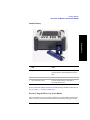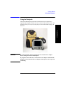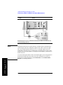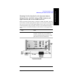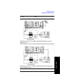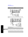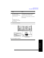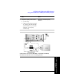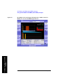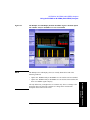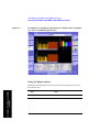
1
Measurement Guide
Agilent Technologies E7495A/B
Base Station Test Set
For firmware revision A.06.20 and above
Manufacturing Part Number: E7495-90054
Supersedes E7495-90053
Printed in USA
December 2008
© Copyright 2002–2008 Agilent Technologies, Inc.
Notice
The material contained in this document is provided “as is,” and is subject to being
changed, without notice, in future editions. Further, to the maximum extent
permitted by applicable law, Agilent disclaims all warranties, either express or
implied with regard to this manual and any information contained herein, including
but not limited to the implied warranties of merchantability and fitness for a
particular purpose. Agilent shall not be liable for errors or for incidental or
consequential damages in connection with the furnishing, use, or performance of
this document or any information contained herein. Should Agilent and the user
have a separate written agreement with warranty terms covering the material in this
document that conflict with these terms, the warranty terms in the separate
agreement will control.”
Technology Licenses
The hardware and/or software described in this document are furnished under a
license and may be used or copied only in accordance with the terms of such license.
Restricted Rights Legend
If software is for use in the performance of a U.S. Government prime contract or
subcontract, Software is delivered and licensed as “Commercial computer software”
as defined in DFAR 252.227-7014 (June 1995), or as a “commercial item” as
defined in FAR 2.101(a) or as “Restricted computer software” as defined in FAR
52.227-19 (June 1987) or any equivalent agency regulation or contract clause. Use,
duplication or disclosure of Software is subject to Agilent Technologies’ standard
commercial license terms, and non-DOD Departments and Agencies of the U.S.
Government will receive no greater than Restricted Rights as defined in FAR
52.227-19(c)(1-2) (June 1987). U.S. Government users will receive no greater than
Limited Rights as defined in FAR 52.227-14 (June 1987) or DFAR 252.227-7015
(b)(2) (November 1995), as applicable in any technical data.
2
Where to Find the Latest Information
Documentation is updated periodically. For the latest information about Agilent
Technologies E7495 spectrum analyzers, including firmware upgrades and
application information, please visit the following URL:
http://www.agilent.com/find/e7495b
Microsoft® is a U.S. registered trademark of Microsoft Corporation.
3
4
Contents
Table of Contents
1. Getting Started
Introduction. . . . . . . . . . . . . . . . . . . . . . . . . . . . . . . . . . . . . . . . . . . . . . . . . . . . . . . . . . . . . . . . . . . . .20
Unpacking the E7495A/B Test Set . . . . . . . . . . . . . . . . . . . . . . . . . . . . . . . . . . . . . . . . . . . . . . . . . . .22
E7495A/B Cables, Connectors, and Accessories . . . . . . . . . . . . . . . . . . . . . . . . . . . . . . . . . . . . . .24
Test set options . . . . . . . . . . . . . . . . . . . . . . . . . . . . . . . . . . . . . . . . . . . . . . . . . . . . . . . . . . . . . . . .28
Your First 15 Minutes with the E7495A/B . . . . . . . . . . . . . . . . . . . . . . . . . . . . . . . . . . . . . . . . . . . . .33
Get to Know the Layout of the E7495A/B . . . . . . . . . . . . . . . . . . . . . . . . . . . . . . . . . . . . . . . . . . .34
Install a Battery . . . . . . . . . . . . . . . . . . . . . . . . . . . . . . . . . . . . . . . . . . . . . . . . . . . . . . . . . . . . . . . .37
Practice Using the Three-way Power Button . . . . . . . . . . . . . . . . . . . . . . . . . . . . . . . . . . . . . . . . .37
Make Your First Measurement (Two Port Insertion Loss) . . . . . . . . . . . . . . . . . . . . . . . . . . . . . . .38
Using the Backpack . . . . . . . . . . . . . . . . . . . . . . . . . . . . . . . . . . . . . . . . . . . . . . . . . . . . . . . . . . . . . .41
What Goes Where in the Backpack. . . . . . . . . . . . . . . . . . . . . . . . . . . . . . . . . . . . . . . . . . . . . . . . .42
Contacting Agilent Technologies . . . . . . . . . . . . . . . . . . . . . . . . . . . . . . . . . . . . . . . . . . . . . . . . . . . .43
More Information from Agilent . . . . . . . . . . . . . . . . . . . . . . . . . . . . . . . . . . . . . . . . . . . . . . . . . . .43
E7495A/B Base Station Test Set Product Updates . . . . . . . . . . . . . . . . . . . . . . . . . . . . . . . . . . . . .43
2. One Port Insertion Loss
Measuring One Port Insertion Loss . . . . . . . . . . . . . . . . . . . . . . . . . . . . . . . . . . . . . . . . . . . . . . . . . .46
Calibration - Minimizing your Workload . . . . . . . . . . . . . . . . . . . . . . . . . . . . . . . . . . . . . . . . . . . .46
Performing (and Calibrating) a Basic One Port Insertion Loss measurement . . . . . . . . . . . . . . . .47
Clearing Calibration . . . . . . . . . . . . . . . . . . . . . . . . . . . . . . . . . . . . . . . . . . . . . . . . . . . . . . . . . . . .50
Displaying Location Information Using GPS . . . . . . . . . . . . . . . . . . . . . . . . . . . . . . . . . . . . . . . .51
Setting Average, Sweep, and Restart. . . . . . . . . . . . . . . . . . . . . . . . . . . . . . . . . . . . . . . . . . . . . . . .52
Adding a Marker . . . . . . . . . . . . . . . . . . . . . . . . . . . . . . . . . . . . . . . . . . . . . . . . . . . . . . . . . . . . . . .55
Setting One Port Insertion Loss Interference Rejection . . . . . . . . . . . . . . . . . . . . . . . . . . . . . . . . .56
Setting the Pass/Fail Limits. . . . . . . . . . . . . . . . . . . . . . . . . . . . . . . . . . . . . . . . . . . . . . . . . . . . . . .57
3. 1xEV-DO Analyzer and Over Air Test
Accessing 1xEV-DO Tx and Over Air Test . . . . . . . . . . . . . . . . . . . . . . . . . . . . . . . . . . . . . . . . . . . .60
Making 1xEV-DO Tx Measurements . . . . . . . . . . . . . . . . . . . . . . . . . . . . . . . . . . . . . . . . . . . . . . . . .61
Common 1xEVDO Tx Analyzer Measurements . . . . . . . . . . . . . . . . . . . . . . . . . . . . . . . . . . . . . .61
Performing a Basic 1xEVDO Transmitter Measurement . . . . . . . . . . . . . . . . . . . . . . . . . . . . . . . . . .63
Making 1xEV-DO Over Air Measurements . . . . . . . . . . . . . . . . . . . . . . . . . . . . . . . . . . . . . . . . . . . .67
Preparing to Make 1xEV-DO Over Air Measurements . . . . . . . . . . . . . . . . . . . . . . . . . . . . . . . . . . .68
Criteria for Making Valid 1xEV-DO Over Air Measurements . . . . . . . . . . . . . . . . . . . . . . . . . . . . .69
Performing a Basic 1xEV-DO Over Air Measurement . . . . . . . . . . . . . . . . . . . . . . . . . . . . . . . . . . .71
5
Table of Contents
Contents
Displaying Location Information Using GPS . . . . . . . . . . . . . . . . . . . . . . . . . . . . . . . . . . . . . . . . . . 74
Interpreting the Display . . . . . . . . . . . . . . . . . . . . . . . . . . . . . . . . . . . . . . . . . . . . . . . . . . . . . . . . . . . 75
Optional 1xEV-DO Tx and Over Air Analyzer Measurement Settings . . . . . . . . . . . . . . . . . . . . . . . 77
Setting the Channel or Frequency Step. . . . . . . . . . . . . . . . . . . . . . . . . . . . . . . . . . . . . . . . . . . . . . 77
Setting the PN Offset . . . . . . . . . . . . . . . . . . . . . . . . . . . . . . . . . . . . . . . . . . . . . . . . . . . . . . . . . . . 79
Setting the PN Increment . . . . . . . . . . . . . . . . . . . . . . . . . . . . . . . . . . . . . . . . . . . . . . . . . . . . . . . . 79
Setting the Active Channel Threshold Level and Auto Threshold Level. . . . . . . . . . . . . . . . . . . . 80
Setting the Frequency/Time Reference. . . . . . . . . . . . . . . . . . . . . . . . . . . . . . . . . . . . . . . . . . . . . . 81
Setting Units . . . . . . . . . . . . . . . . . . . . . . . . . . . . . . . . . . . . . . . . . . . . . . . . . . . . . . . . . . . . . . . . . . 82
Setting the 1xEV-DO Transmitter Reference Level . . . . . . . . . . . . . . . . . . . . . . . . . . . . . . . . . . . . 82
Setting Measurement Time . . . . . . . . . . . . . . . . . . . . . . . . . . . . . . . . . . . . . . . . . . . . . . . . . . . . . . . 83
Setting Measurement Offset . . . . . . . . . . . . . . . . . . . . . . . . . . . . . . . . . . . . . . . . . . . . . . . . . . . . . . 84
Setting the Slot Threshold Level . . . . . . . . . . . . . . . . . . . . . . . . . . . . . . . . . . . . . . . . . . . . . . . . . . 85
Setting the CDP Type . . . . . . . . . . . . . . . . . . . . . . . . . . . . . . . . . . . . . . . . . . . . . . . . . . . . . . . . . . . 85
Setting the Pilot Dominance Limit . . . . . . . . . . . . . . . . . . . . . . . . . . . . . . . . . . . . . . . . . . . . . . . . . 86
Setting the Multipath Power Limit . . . . . . . . . . . . . . . . . . . . . . . . . . . . . . . . . . . . . . . . . . . . . . . . . 87
Setting the PN Scanner Sensitivity . . . . . . . . . . . . . . . . . . . . . . . . . . . . . . . . . . . . . . . . . . . . . . . . . 87
Setting Average, Sweep, and Restart . . . . . . . . . . . . . . . . . . . . . . . . . . . . . . . . . . . . . . . . . . . . . . . 88
Adding a Marker . . . . . . . . . . . . . . . . . . . . . . . . . . . . . . . . . . . . . . . . . . . . . . . . . . . . . . . . . . . . . . . 90
Setting the Pass/Fail Limits . . . . . . . . . . . . . . . . . . . . . . . . . . . . . . . . . . . . . . . . . . . . . . . . . . . . . . 92
Setting Up the Signal Generator . . . . . . . . . . . . . . . . . . . . . . . . . . . . . . . . . . . . . . . . . . . . . . . . . . 101
Metrics Provided by the 1xEV-DO Tx and Over Air Analyzer Measurement . . . . . . . . . . . . . . . . 104
Interpretation of 1xEV-DO Tx and Over Air Analyzer Measurement Results . . . . . . . . . . . . . . . . 109
Customizing Your Display . . . . . . . . . . . . . . . . . . . . . . . . . . . . . . . . . . . . . . . . . . . . . . . . . . . . . . . . 114
Sorting by MAC Index or by Walsh Code . . . . . . . . . . . . . . . . . . . . . . . . . . . . . . . . . . . . . . . . . . . . 115
Converting Between MAC Index and Walsh Code . . . . . . . . . . . . . . . . . . . . . . . . . . . . . . . . . . . . . 116
Colors Used on the MAC Code Domain CDP Display . . . . . . . . . . . . . . . . . . . . . . . . . . . . . . . . . . 117
Colors Used on the Pilot Code Domain CDP Display . . . . . . . . . . . . . . . . . . . . . . . . . . . . . . . . . . . 118
Showing or Hiding the OTA PN Scanner. . . . . . . . . . . . . . . . . . . . . . . . . . . . . . . . . . . . . . . . . . . . . 119
Codogram Display . . . . . . . . . . . . . . . . . . . . . . . . . . . . . . . . . . . . . . . . . . . . . . . . . . . . . . . . . . . . . . 120
Performing a Codogram Measurement . . . . . . . . . . . . . . . . . . . . . . . . . . . . . . . . . . . . . . . . . . . . . . 121
4. Two Port Insertion Loss
Measuring Two Port Insertion Loss . . . . . . . . . . . . . . . . . . . . . . . . . . . . . . . . . . . . . . . . . . . . . . . . . 124
Normalizing and Performing a Basic Two Port Insertion Loss Measurement . . . . . . . . . . . . . . 125
Displaying Location Information Using GPS. . . . . . . . . . . . . . . . . . . . . . . . . . . . . . . . . . . . . . . . 126
6
Contents
Table of Contents
Setting Average, Sweep, and Restart. . . . . . . . . . . . . . . . . . . . . . . . . . . . . . . . . . . . . . . . . . . . . . .127
Adding a Marker . . . . . . . . . . . . . . . . . . . . . . . . . . . . . . . . . . . . . . . . . . . . . . . . . . . . . . . . . . . . . .130
Measuring Two Port Insertion Loss for Spectrum Analyzer, Channel Scanner, 1xEV-DO Analyzer,
CDMA Analyzer, and Signal Generator (RF In Loss and RF Out Loss) . . . . . . . . . . . . . . . . . . .131
Measuring Insertion Loss for Power Meter (Option 600 - Power Meter Only) . . . . . . . . . . . . . .134
Determining The Lowest (Worst) Insertion Loss and Its Frequency . . . . . . . . . . . . . . . . . . . . . .135
Determining the Highest (Best) Insertion Loss and Its Frequency . . . . . . . . . . . . . . . . . . . . . . . .136
Using the Delta Marker to Measure a Difference in Insertion Loss or Frequency . . . . . . . . . . .136
Activating Interference Rejection . . . . . . . . . . . . . . . . . . . . . . . . . . . . . . . . . . . . . . . . . . . . . . . . .136
Clearing Normalization . . . . . . . . . . . . . . . . . . . . . . . . . . . . . . . . . . . . . . . . . . . . . . . . . . . . . . . .137
Setting Source Level . . . . . . . . . . . . . . . . . . . . . . . . . . . . . . . . . . . . . . . . . . . . . . . . . . . . . . . . . . .137
Optimizing Dynamic Range . . . . . . . . . . . . . . . . . . . . . . . . . . . . . . . . . . . . . . . . . . . . . . . . . . . . .139
Setting the Pass/Fail Limits. . . . . . . . . . . . . . . . . . . . . . . . . . . . . . . . . . . . . . . . . . . . . . . . . . . . . .140
5. Adjacent Channel Power
Using the Adjacent Channel Power Measurement . . . . . . . . . . . . . . . . . . . . . . . . . . . . . . . . . . . . . .142
Making a Basic Adjacent Channel Power Measurement . . . . . . . . . . . . . . . . . . . . . . . . . . . . . . .143
Adjacent Channel Power Measurements for Korean PCS Band. . . . . . . . . . . . . . . . . . . . . . . . . .145
Setting the Adjacent Channel Power Format . . . . . . . . . . . . . . . . . . . . . . . . . . . . . . . . . . . . . . . .145
Setting Average, Sweep, and Restart. . . . . . . . . . . . . . . . . . . . . . . . . . . . . . . . . . . . . . . . . . . . . . .150
Displaying Accurate Peak Power (Recommended for Pulsed Signals) . . . . . . . . . . . . . . . . . . . .152
Setting the Control Units. . . . . . . . . . . . . . . . . . . . . . . . . . . . . . . . . . . . . . . . . . . . . . . . . . . . . . . .152
Setting the Range Control . . . . . . . . . . . . . . . . . . . . . . . . . . . . . . . . . . . . . . . . . . . . . . . . . . . . . . .153
Setting the Analyzer Input Gain . . . . . . . . . . . . . . . . . . . . . . . . . . . . . . . . . . . . . . . . . . . . . . . . . .154
Setting Noise Correction . . . . . . . . . . . . . . . . . . . . . . . . . . . . . . . . . . . . . . . . . . . . . . . . . . . . . . . .154
Setting the Pass/Fail Limits. . . . . . . . . . . . . . . . . . . . . . . . . . . . . . . . . . . . . . . . . . . . . . . . . . . . . .155
Setting Up the Signal Generator . . . . . . . . . . . . . . . . . . . . . . . . . . . . . . . . . . . . . . . . . . . . . . . . . .157
W-CDMA Adjacent Channel Leakage Power Ratio (ACLR) Measurements . . . . . . . . . . . . . . . . .161
6. Working with Batteries
Installing Batteries . . . . . . . . . . . . . . . . . . . . . . . . . . . . . . . . . . . . . . . . . . . . . . . . . . . . . . . . . . . . . .164
Viewing Battery Status . . . . . . . . . . . . . . . . . . . . . . . . . . . . . . . . . . . . . . . . . . . . . . . . . . . . . . . . . . .165
Charging Batteries . . . . . . . . . . . . . . . . . . . . . . . . . . . . . . . . . . . . . . . . . . . . . . . . . . . . . . . . . . . . . .168
Reconditioning Batteries. . . . . . . . . . . . . . . . . . . . . . . . . . . . . . . . . . . . . . . . . . . . . . . . . . . . . . . . . .170
Battery Care . . . . . . . . . . . . . . . . . . . . . . . . . . . . . . . . . . . . . . . . . . . . . . . . . . . . . . . . . . . . . . . . . . .173
Battery Specifications . . . . . . . . . . . . . . . . . . . . . . . . . . . . . . . . . . . . . . . . . . . . . . . . . . . . . . . . . . . .176
7
Table of Contents
Contents
7. CDMA Analyzer
Using the CDMA Analyzer . . . . . . . . . . . . . . . . . . . . . . . . . . . . . . . . . . . . . . . . . . . . . . . . . . . . . . . 182
Common CDMA Tx Analyzer Measurements . . . . . . . . . . . . . . . . . . . . . . . . . . . . . . . . . . . . . . . 182
Performing a Basic CDMA Transmitter Measurement . . . . . . . . . . . . . . . . . . . . . . . . . . . . . . . . 183
Interpreting the Display . . . . . . . . . . . . . . . . . . . . . . . . . . . . . . . . . . . . . . . . . . . . . . . . . . . . . . . . 187
Codogram Display . . . . . . . . . . . . . . . . . . . . . . . . . . . . . . . . . . . . . . . . . . . . . . . . . . . . . . . . . . . . 187
Performing a Codogram Measurement. . . . . . . . . . . . . . . . . . . . . . . . . . . . . . . . . . . . . . . . . . . . . 188
Optional CDMA Tx Analyzer Measurement Settings . . . . . . . . . . . . . . . . . . . . . . . . . . . . . . . . . . . 190
Setting the Channel or Frequency Step. . . . . . . . . . . . . . . . . . . . . . . . . . . . . . . . . . . . . . . . . . . . . 190
Setting the PN Offset . . . . . . . . . . . . . . . . . . . . . . . . . . . . . . . . . . . . . . . . . . . . . . . . . . . . . . . . . . 191
Setting the PN Increment . . . . . . . . . . . . . . . . . . . . . . . . . . . . . . . . . . . . . . . . . . . . . . . . . . . . . . . 191
Setting the Frequency/Time Reference. . . . . . . . . . . . . . . . . . . . . . . . . . . . . . . . . . . . . . . . . . . . . 192
Setting Units . . . . . . . . . . . . . . . . . . . . . . . . . . . . . . . . . . . . . . . . . . . . . . . . . . . . . . . . . . . . . . . . . 193
Setting the CDMA Transmitter Reference Level . . . . . . . . . . . . . . . . . . . . . . . . . . . . . . . . . . . . . 193
Setting the Active Channel Threshold Level and Auto Threshold Level. . . . . . . . . . . . . . . . . . . 194
Setting Measurement Time . . . . . . . . . . . . . . . . . . . . . . . . . . . . . . . . . . . . . . . . . . . . . . . . . . . . . . 195
Setting Quick Page Channel . . . . . . . . . . . . . . . . . . . . . . . . . . . . . . . . . . . . . . . . . . . . . . . . . . . . . 196
Setting Average, Sweep, and Restart . . . . . . . . . . . . . . . . . . . . . . . . . . . . . . . . . . . . . . . . . . . . . . 197
Adding a Marker . . . . . . . . . . . . . . . . . . . . . . . . . . . . . . . . . . . . . . . . . . . . . . . . . . . . . . . . . . . . . . 198
Setting the Pass/Fail Limits . . . . . . . . . . . . . . . . . . . . . . . . . . . . . . . . . . . . . . . . . . . . . . . . . . . . . 200
Setting Up the Signal Generator . . . . . . . . . . . . . . . . . . . . . . . . . . . . . . . . . . . . . . . . . . . . . . . . . . 209
Metrics Provided by the CDMA Tx Analyzer Measurement. . . . . . . . . . . . . . . . . . . . . . . . . . . . . . 212
Interpretation of CDMA Tx Analyzer Measurement Results . . . . . . . . . . . . . . . . . . . . . . . . . . . . . 214
8. CDMA Over Air
Using the CDMA Over Air Tool . . . . . . . . . . . . . . . . . . . . . . . . . . . . . . . . . . . . . . . . . . . . . . . . . . . 220
Preparing to Make CDMA Over Air Measurements . . . . . . . . . . . . . . . . . . . . . . . . . . . . . . . . . . 220
Criteria for Making Valid CDMA Over Air Measurements . . . . . . . . . . . . . . . . . . . . . . . . . . . . 221
Performing a Basic CDMA Over Air Measurement . . . . . . . . . . . . . . . . . . . . . . . . . . . . . . . . . . 222
Displaying Location Information Using GPS. . . . . . . . . . . . . . . . . . . . . . . . . . . . . . . . . . . . . . . . 224
Codogram Display . . . . . . . . . . . . . . . . . . . . . . . . . . . . . . . . . . . . . . . . . . . . . . . . . . . . . . . . . . . . 226
Performing a Codogram Measurement. . . . . . . . . . . . . . . . . . . . . . . . . . . . . . . . . . . . . . . . . . . . . 226
Setting Amplifier Capacity Metrics . . . . . . . . . . . . . . . . . . . . . . . . . . . . . . . . . . . . . . . . . . . . . . . 227
Interpreting the Display . . . . . . . . . . . . . . . . . . . . . . . . . . . . . . . . . . . . . . . . . . . . . . . . . . . . . . . . 229
Optional CDMA Over Air Measurement Settings . . . . . . . . . . . . . . . . . . . . . . . . . . . . . . . . . . . . . . 231
Setting the Channel or Frequency Step. . . . . . . . . . . . . . . . . . . . . . . . . . . . . . . . . . . . . . . . . . . . . 231
8
Contents
Table of Contents
Setting the PN Increment . . . . . . . . . . . . . . . . . . . . . . . . . . . . . . . . . . . . . . . . . . . . . . . . . . . . . . .232
Setting the Transmitter Reference Level. . . . . . . . . . . . . . . . . . . . . . . . . . . . . . . . . . . . . . . . . . . .232
Setting the Active Channel Threshold Level and Auto Threshold Level . . . . . . . . . . . . . . . . . . .234
Resetting Amplifier Capacity and Traffic Metrics . . . . . . . . . . . . . . . . . . . . . . . . . . . . . . . . . . . .235
Setting Measurement Time . . . . . . . . . . . . . . . . . . . . . . . . . . . . . . . . . . . . . . . . . . . . . . . . . . . . . .235
Setting Quick Page Channel . . . . . . . . . . . . . . . . . . . . . . . . . . . . . . . . . . . . . . . . . . . . . . . . . . . . .236
Setting Average, Sweep, and Restart. . . . . . . . . . . . . . . . . . . . . . . . . . . . . . . . . . . . . . . . . . . . . . .237
Adding a Marker . . . . . . . . . . . . . . . . . . . . . . . . . . . . . . . . . . . . . . . . . . . . . . . . . . . . . . . . . . . . . .238
Setting the Pass/Fail Limits. . . . . . . . . . . . . . . . . . . . . . . . . . . . . . . . . . . . . . . . . . . . . . . . . . . . . .240
Setting Up the Signal Generator . . . . . . . . . . . . . . . . . . . . . . . . . . . . . . . . . . . . . . . . . . . . . . . . . .249
Metrics Provided by CDMA Over Air Measurements . . . . . . . . . . . . . . . . . . . . . . . . . . . . . . . . . . .252
Interpretation of CDMA Over Air Measurement Results . . . . . . . . . . . . . . . . . . . . . . . . . . . . . . . .256
9. Channel Scanner
Using the Channel Scanner. . . . . . . . . . . . . . . . . . . . . . . . . . . . . . . . . . . . . . . . . . . . . . . . . . . . . . . .262
Performing a Basic Channel Scanner Measurement) . . . . . . . . . . . . . . . . . . . . . . . . . . . . . . . . . .263
Displaying Accurate Peak Power (Recommended for Pulsed Signals) . . . . . . . . . . . . . . . . . . . .266
Setting the Analyzer Input Gain . . . . . . . . . . . . . . . . . . . . . . . . . . . . . . . . . . . . . . . . . . . . . . . . . .267
Setting Noise Correction . . . . . . . . . . . . . . . . . . . . . . . . . . . . . . . . . . . . . . . . . . . . . . . . . . . . . . . .267
Entering the Channels with a List Instead of a Range . . . . . . . . . . . . . . . . . . . . . . . . . . . . . . . . .268
Entering the Channel Power Measurement Bandwidth and Time . . . . . . . . . . . . . . . . . . . . . . . .269
Setting Average, Sweep, and Restart. . . . . . . . . . . . . . . . . . . . . . . . . . . . . . . . . . . . . . . . . . . . . . .272
Displaying Frequency or Power . . . . . . . . . . . . . . . . . . . . . . . . . . . . . . . . . . . . . . . . . . . . . . . . . .274
Setting the Pass/Fail Limits. . . . . . . . . . . . . . . . . . . . . . . . . . . . . . . . . . . . . . . . . . . . . . . . . . . . . .274
10. Distance to Fault
Measuring Distance to Fault . . . . . . . . . . . . . . . . . . . . . . . . . . . . . . . . . . . . . . . . . . . . . . . . . . . . . . .278
Measured Distance - the Effects of Frequency and Points . . . . . . . . . . . . . . . . . . . . . . . . . . . . . .278
Resolution - the Effects of Frequency and Points . . . . . . . . . . . . . . . . . . . . . . . . . . . . . . . . . . . . .279
Automatic and Manual Distance to Fault Measurements . . . . . . . . . . . . . . . . . . . . . . . . . . . . . . .279
Calibration - Minimizing your Workload . . . . . . . . . . . . . . . . . . . . . . . . . . . . . . . . . . . . . . . . . . .281
Performing a Basic Distance to Fault Measurement
(Manual Frequency Range). . . . . . . . . . . . . . . . . . . . . . . . . . . . . . . . . . . . . . . . . . . . . . . . . . . . . .283
Performing a Basic Distance to Fault Measurement
(Automatic Frequency Range) . . . . . . . . . . . . . . . . . . . . . . . . . . . . . . . . . . . . . . . . . . . . . . . . . . .286
Clearing Calibration . . . . . . . . . . . . . . . . . . . . . . . . . . . . . . . . . . . . . . . . . . . . . . . . . . . . . . . . . . .290
9
Table of Contents
Contents
Displaying Location Information Using GPS. . . . . . . . . . . . . . . . . . . . . . . . . . . . . . . . . . . . . . . . 291
Viewing a Single Distance to Fault Sweep . . . . . . . . . . . . . . . . . . . . . . . . . . . . . . . . . . . . . . . . . . 292
Displaying the Top Four Faults. . . . . . . . . . . . . . . . . . . . . . . . . . . . . . . . . . . . . . . . . . . . . . . . . . . 292
Setting Interference Rejection for a Distance to Fault Measurement . . . . . . . . . . . . . . . . . . . . . . 293
Setting Average, Sweep, and Restart . . . . . . . . . . . . . . . . . . . . . . . . . . . . . . . . . . . . . . . . . . . . . . 294
Adding a Marker . . . . . . . . . . . . . . . . . . . . . . . . . . . . . . . . . . . . . . . . . . . . . . . . . . . . . . . . . . . . . . 296
Setting the Pass/Fail Limits . . . . . . . . . . . . . . . . . . . . . . . . . . . . . . . . . . . . . . . . . . . . . . . . . . . . . 297
11. E1 Analyzer
Making E1 Measurements . . . . . . . . . . . . . . . . . . . . . . . . . . . . . . . . . . . . . . . . . . . . . . . . . . . . . . . . 300
Steps for Performing a Basic E1 Analyzer Measurement . . . . . . . . . . . . . . . . . . . . . . . . . . . . . . 300
Setup Button Selections . . . . . . . . . . . . . . . . . . . . . . . . . . . . . . . . . . . . . . . . . . . . . . . . . . . . . . . . 300
Display/Sound Button Selections . . . . . . . . . . . . . . . . . . . . . . . . . . . . . . . . . . . . . . . . . . . . . . . . . 303
Control Button Selections . . . . . . . . . . . . . . . . . . . . . . . . . . . . . . . . . . . . . . . . . . . . . . . . . . . . . . . 303
Sample Hard Loop/End-End Full E1 BERT Test . . . . . . . . . . . . . . . . . . . . . . . . . . . . . . . . . . . . . 305
Sample Monitor Full E1 Test . . . . . . . . . . . . . . . . . . . . . . . . . . . . . . . . . . . . . . . . . . . . . . . . . . . . 308
Setting Up Delay Test Mode. . . . . . . . . . . . . . . . . . . . . . . . . . . . . . . . . . . . . . . . . . . . . . . . . . . . . 312
Turning On Sound. . . . . . . . . . . . . . . . . . . . . . . . . . . . . . . . . . . . . . . . . . . . . . . . . . . . . . . . . . . . . 314
Setting Up E1 Diagnostics . . . . . . . . . . . . . . . . . . . . . . . . . . . . . . . . . . . . . . . . . . . . . . . . . . . . . . 315
Patterns . . . . . . . . . . . . . . . . . . . . . . . . . . . . . . . . . . . . . . . . . . . . . . . . . . . . . . . . . . . . . . . . . . . . . 316
Measurement Results . . . . . . . . . . . . . . . . . . . . . . . . . . . . . . . . . . . . . . . . . . . . . . . . . . . . . . . . . . . . 318
Alarm Indicators . . . . . . . . . . . . . . . . . . . . . . . . . . . . . . . . . . . . . . . . . . . . . . . . . . . . . . . . . . . . . . 318
Results Indicators . . . . . . . . . . . . . . . . . . . . . . . . . . . . . . . . . . . . . . . . . . . . . . . . . . . . . . . . . . . . . 318
Status Indicators . . . . . . . . . . . . . . . . . . . . . . . . . . . . . . . . . . . . . . . . . . . . . . . . . . . . . . . . . . . . . . 320
Testing and Fault Mitigation. . . . . . . . . . . . . . . . . . . . . . . . . . . . . . . . . . . . . . . . . . . . . . . . . . . . . 321
More Information About E1 Testing . . . . . . . . . . . . . . . . . . . . . . . . . . . . . . . . . . . . . . . . . . . . . . . . 323
Auto Configuration Flow Diagram. . . . . . . . . . . . . . . . . . . . . . . . . . . . . . . . . . . . . . . . . . . . . . . . 323
Terminology . . . . . . . . . . . . . . . . . . . . . . . . . . . . . . . . . . . . . . . . . . . . . . . . . . . . . . . . . . . . . . . . . 325
12. GSM and EDGE Analyzer
Using the GSM Analyzer and the EDGE Analyzer . . . . . . . . . . . . . . . . . . . . . . . . . . . . . . . . . . . . . 329
Performing a Basic GSM or EDGE Transmitter Measurement . . . . . . . . . . . . . . . . . . . . . . . . . . 330
Interpreting the Display . . . . . . . . . . . . . . . . . . . . . . . . . . . . . . . . . . . . . . . . . . . . . . . . . . . . . . . . 335
Optional GSM and EDGE Tx Analyzer Measurement Settings . . . . . . . . . . . . . . . . . . . . . . . . . . . 339
Setting your Scan Mode . . . . . . . . . . . . . . . . . . . . . . . . . . . . . . . . . . . . . . . . . . . . . . . . . . . . . . . . 340
Adding or Deleting a List Item . . . . . . . . . . . . . . . . . . . . . . . . . . . . . . . . . . . . . . . . . . . . . . . . . . . 342
10
Contents
Table of Contents
Setting the Start Frequency/Channel. . . . . . . . . . . . . . . . . . . . . . . . . . . . . . . . . . . . . . . . . . . . . . .343
Setting the Frequency or Channel Step Size . . . . . . . . . . . . . . . . . . . . . . . . . . . . . . . . . . . . . . . . .344
Setting the Stop Frequency/Channel . . . . . . . . . . . . . . . . . . . . . . . . . . . . . . . . . . . . . . . . . . . . . . .345
Setting the Channel Standard . . . . . . . . . . . . . . . . . . . . . . . . . . . . . . . . . . . . . . . . . . . . . . . . . . . .346
Setting the Units of Measure for the Graphical Display . . . . . . . . . . . . . . . . . . . . . . . . . . . . . . . .346
Setting Autoscale. . . . . . . . . . . . . . . . . . . . . . . . . . . . . . . . . . . . . . . . . . . . . . . . . . . . . . . . . . . . . .347
Setting the Reference Level . . . . . . . . . . . . . . . . . . . . . . . . . . . . . . . . . . . . . . . . . . . . . . . . . . . . .348
Setting Scale/Division . . . . . . . . . . . . . . . . . . . . . . . . . . . . . . . . . . . . . . . . . . . . . . . . . . . . . . . . . .348
Using GPS for Frequency Reference and Location Information . . . . . . . . . . . . . . . . . . . . . . . . .348
Setting the Display Position . . . . . . . . . . . . . . . . . . . . . . . . . . . . . . . . . . . . . . . . . . . . . . . . . . . . .349
Setting Auto Order . . . . . . . . . . . . . . . . . . . . . . . . . . . . . . . . . . . . . . . . . . . . . . . . . . . . . . . . . . . .350
Setting Bar Top and Units . . . . . . . . . . . . . . . . . . . . . . . . . . . . . . . . . . . . . . . . . . . . . . . . . . . . . . .350
Setting Mid-Bar. . . . . . . . . . . . . . . . . . . . . . . . . . . . . . . . . . . . . . . . . . . . . . . . . . . . . . . . . . . . . . .351
Setting Zoom . . . . . . . . . . . . . . . . . . . . . . . . . . . . . . . . . . . . . . . . . . . . . . . . . . . . . . . . . . . . . . . . .351
Setting Zoom Offset . . . . . . . . . . . . . . . . . . . . . . . . . . . . . . . . . . . . . . . . . . . . . . . . . . . . . . . . . . .352
Setting Zoom Interval . . . . . . . . . . . . . . . . . . . . . . . . . . . . . . . . . . . . . . . . . . . . . . . . . . . . . . . . . .353
Setting PvT Mask . . . . . . . . . . . . . . . . . . . . . . . . . . . . . . . . . . . . . . . . . . . . . . . . . . . . . . . . . . . . .354
Setting Auto Mode Bar Count. . . . . . . . . . . . . . . . . . . . . . . . . . . . . . . . . . . . . . . . . . . . . . . . . . . .354
Setting Slot Synchronization. . . . . . . . . . . . . . . . . . . . . . . . . . . . . . . . . . . . . . . . . . . . . . . . . . . . .355
Setting TS# (w/ BCCH) . . . . . . . . . . . . . . . . . . . . . . . . . . . . . . . . . . . . . . . . . . . . . . . . . . . . . . . .356
Setting the Pass/Fail Limits. . . . . . . . . . . . . . . . . . . . . . . . . . . . . . . . . . . . . . . . . . . . . . . . . . . . . .357
Adding a Marker . . . . . . . . . . . . . . . . . . . . . . . . . . . . . . . . . . . . . . . . . . . . . . . . . . . . . . . . . . . . . .365
Compensating for the Loss of an External Cable and Attenuator. . . . . . . . . . . . . . . . . . . . . . . . .367
Setting Average, Sweep, and Restart. . . . . . . . . . . . . . . . . . . . . . . . . . . . . . . . . . . . . . . . . . . . . . .368
GSM and EDGE Modulation and Band Information . . . . . . . . . . . . . . . . . . . . . . . . . . . . . . . . . . . .371
Metrics Provided by the GSM and EDGE Analyzer Measurement . . . . . . . . . . . . . . . . . . . . . . . . .373
Interpretation of GSM and EDGE Analyzer Measurement Results . . . . . . . . . . . . . . . . . . . . . . . . .376
13. Power Meter
Making an Average Power Measurement . . . . . . . . . . . . . . . . . . . . . . . . . . . . . . . . . . . . . . . . . . . . .380
Making a Basic Average Power Measurement . . . . . . . . . . . . . . . . . . . . . . . . . . . . . . . . . . . . . . .381
Setting Power Meter Resolution . . . . . . . . . . . . . . . . . . . . . . . . . . . . . . . . . . . . . . . . . . . . . . . . . .384
Setting the Power Meter’s High and Low End-Points . . . . . . . . . . . . . . . . . . . . . . . . . . . . . . . . .385
Setting the Power Meter’s Upper and Lower Limits . . . . . . . . . . . . . . . . . . . . . . . . . . . . . . . . . .386
14. Return Loss
11
Table of Contents
Contents
Measuring Return Loss. . . . . . . . . . . . . . . . . . . . . . . . . . . . . . . . . . . . . . . . . . . . . . . . . . . . . . . . . . . 390
Calibration - Minimizing your Workload . . . . . . . . . . . . . . . . . . . . . . . . . . . . . . . . . . . . . . . . . . . 390
Performing (and Calibrating) a Basic Return Loss Measurement . . . . . . . . . . . . . . . . . . . . . . . . 391
Clearing Calibration . . . . . . . . . . . . . . . . . . . . . . . . . . . . . . . . . . . . . . . . . . . . . . . . . . . . . . . . . . . 394
Isolating a Return Loss Signal Using a Single Sweep . . . . . . . . . . . . . . . . . . . . . . . . . . . . . . . . . 395
Setting Return Loss Interference Rejection . . . . . . . . . . . . . . . . . . . . . . . . . . . . . . . . . . . . . . . . . 395
Setting Average, Sweep, and Restart . . . . . . . . . . . . . . . . . . . . . . . . . . . . . . . . . . . . . . . . . . . . . . 396
Adding a Marker . . . . . . . . . . . . . . . . . . . . . . . . . . . . . . . . . . . . . . . . . . . . . . . . . . . . . . . . . . . . . . 398
Displaying Location Information Using GPS . . . . . . . . . . . . . . . . . . . . . . . . . . . . . . . . . . . . . . . 399
Setting the Pass/Fail Limits . . . . . . . . . . . . . . . . . . . . . . . . . . . . . . . . . . . . . . . . . . . . . . . . . . . . . 400
15. Signal Generator
Using the Signal Generator . . . . . . . . . . . . . . . . . . . . . . . . . . . . . . . . . . . . . . . . . . . . . . . . . . . . . . . 402
Minimum and Maximum Power levels for Generated Signals. . . . . . . . . . . . . . . . . . . . . . . . . . . 403
Performing a Basic Signal Generator Measurement. . . . . . . . . . . . . . . . . . . . . . . . . . . . . . . . . . . 404
Using the RF OUT Loss field . . . . . . . . . . . . . . . . . . . . . . . . . . . . . . . . . . . . . . . . . . . . . . . . . . . 410
Persistent Signal Generator . . . . . . . . . . . . . . . . . . . . . . . . . . . . . . . . . . . . . . . . . . . . . . . . . . . . . 411
16. Spectrum Analyzer
Using the Spectrum Analyzer. . . . . . . . . . . . . . . . . . . . . . . . . . . . . . . . . . . . . . . . . . . . . . . . . . . . . . 414
Performing a Basic Spectrum Analyzer Measurement. . . . . . . . . . . . . . . . . . . . . . . . . . . . . . . . . 415
Setting the Range Control. . . . . . . . . . . . . . . . . . . . . . . . . . . . . . . . . . . . . . . . . . . . . . . . . . . . . . . 418
Setting the Analyzer Input Gain . . . . . . . . . . . . . . . . . . . . . . . . . . . . . . . . . . . . . . . . . . . . . . . . . . 419
Setting the Analyzer Detector. . . . . . . . . . . . . . . . . . . . . . . . . . . . . . . . . . . . . . . . . . . . . . . . . . . . 420
Setting Up the Signal Generator . . . . . . . . . . . . . . . . . . . . . . . . . . . . . . . . . . . . . . . . . . . . . . . . . . 421
Setting Average, Sweep, and Restart . . . . . . . . . . . . . . . . . . . . . . . . . . . . . . . . . . . . . . . . . . . . . . 423
Changing the Resolution Bandwidth . . . . . . . . . . . . . . . . . . . . . . . . . . . . . . . . . . . . . . . . . . . . . . 425
Adding or Removing a Marker . . . . . . . . . . . . . . . . . . . . . . . . . . . . . . . . . . . . . . . . . . . . . . . . . . . 426
Setting the Pass/Fail Limits . . . . . . . . . . . . . . . . . . . . . . . . . . . . . . . . . . . . . . . . . . . . . . . . . . . . . 428
Spectrogram Display . . . . . . . . . . . . . . . . . . . . . . . . . . . . . . . . . . . . . . . . . . . . . . . . . . . . . . . . . . . . 435
Performing a Spectrogram Measurement . . . . . . . . . . . . . . . . . . . . . . . . . . . . . . . . . . . . . . . . . . . 436
Using the Interference ID Measurement . . . . . . . . . . . . . . . . . . . . . . . . . . . . . . . . . . . . . . . . . . . . . 439
Performing a Basic Interference ID Measurement . . . . . . . . . . . . . . . . . . . . . . . . . . . . . . . . . . . . 439
Using the Occupied BW Measurement . . . . . . . . . . . . . . . . . . . . . . . . . . . . . . . . . . . . . . . . . . . . . . 444
Performing a Basic Occupied BW Measurement . . . . . . . . . . . . . . . . . . . . . . . . . . . . . . . . . . . . . 445
Using the Spectrum Emission Mask Measurement . . . . . . . . . . . . . . . . . . . . . . . . . . . . . . . . . . . . . 450
12
Contents
Table of Contents
CDMA and 1xEV-DO Channel Standards and Emission Limits . . . . . . . . . . . . . . . . . . . . . . . . .452
W-CDMA UTRA Channel Frequencies and Emission Limits . . . . . . . . . . . . . . . . . . . . . . . . . . .453
Performing a Basic Spectrum Emissions Mask Measurement . . . . . . . . . . . . . . . . . . . . . . . . . . .454
17. Basic System Operations
System Reference Introduction. . . . . . . . . . . . . . . . . . . . . . . . . . . . . . . . . . . . . . . . . . . . . . . . . . . . .461
Setting System References . . . . . . . . . . . . . . . . . . . . . . . . . . . . . . . . . . . . . . . . . . . . . . . . . . . . . . . .462
Displaying GPS Location Data . . . . . . . . . . . . . . . . . . . . . . . . . . . . . . . . . . . . . . . . . . . . . . . . . . .462
Selecting a Frequency/Timing Reference . . . . . . . . . . . . . . . . . . . . . . . . . . . . . . . . . . . . . . . . . . .462
Setting up the DC Bias Option . . . . . . . . . . . . . . . . . . . . . . . . . . . . . . . . . . . . . . . . . . . . . . . . . . .463
Printing a Screen to a File. . . . . . . . . . . . . . . . . . . . . . . . . . . . . . . . . . . . . . . . . . . . . . . . . . . . . . . . .465
Printing Screens. . . . . . . . . . . . . . . . . . . . . . . . . . . . . . . . . . . . . . . . . . . . . . . . . . . . . . . . . . . . . . .465
Selecting Output Media—PCMCIA Card or Compact Flash Card . . . . . . . . . . . . . . . . . . . . . . .465
File Naming Options . . . . . . . . . . . . . . . . . . . . . . . . . . . . . . . . . . . . . . . . . . . . . . . . . . . . . . . . . . .466
Saving Data. . . . . . . . . . . . . . . . . . . . . . . . . . . . . . . . . . . . . . . . . . . . . . . . . . . . . . . . . . . . . . . . . . . .469
Saving data . . . . . . . . . . . . . . . . . . . . . . . . . . . . . . . . . . . . . . . . . . . . . . . . . . . . . . . . . . . . . . . . . .469
Selecting Output Media—PCMCIA Card or Compact Flash Card . . . . . . . . . . . . . . . . . . . . . . .469
File Naming Options . . . . . . . . . . . . . . . . . . . . . . . . . . . . . . . . . . . . . . . . . . . . . . . . . . . . . . . . . . .470
Managing Media Types. . . . . . . . . . . . . . . . . . . . . . . . . . . . . . . . . . . . . . . . . . . . . . . . . . . . . . . . . . .473
Configuring for Network Connectivity. . . . . . . . . . . . . . . . . . . . . . . . . . . . . . . . . . . . . . . . . . . . . . .475
Saving, Recalling, and Deleting Instrument States. . . . . . . . . . . . . . . . . . . . . . . . . . . . . . . . . . . . . .478
Saving the State . . . . . . . . . . . . . . . . . . . . . . . . . . . . . . . . . . . . . . . . . . . . . . . . . . . . . . . . . . . . . . .478
Saving the Power-Up State . . . . . . . . . . . . . . . . . . . . . . . . . . . . . . . . . . . . . . . . . . . . . . . . . . . . . .478
Recalling the State. . . . . . . . . . . . . . . . . . . . . . . . . . . . . . . . . . . . . . . . . . . . . . . . . . . . . . . . . . . . .479
Returning the Power-Up State to Factory default . . . . . . . . . . . . . . . . . . . . . . . . . . . . . . . . . . . . .479
Deleting States. . . . . . . . . . . . . . . . . . . . . . . . . . . . . . . . . . . . . . . . . . . . . . . . . . . . . . . . . . . . . . . .480
Viewing System Statistics. . . . . . . . . . . . . . . . . . . . . . . . . . . . . . . . . . . . . . . . . . . . . . . . . . . . . . . . .481
Viewing System Release Versions . . . . . . . . . . . . . . . . . . . . . . . . . . . . . . . . . . . . . . . . . . . . . . . .481
Viewing System Memory . . . . . . . . . . . . . . . . . . . . . . . . . . . . . . . . . . . . . . . . . . . . . . . . . . . . . . .481
Viewing Battery Statistics . . . . . . . . . . . . . . . . . . . . . . . . . . . . . . . . . . . . . . . . . . . . . . . . . . . . . . .482
Using the Option Manager . . . . . . . . . . . . . . . . . . . . . . . . . . . . . . . . . . . . . . . . . . . . . . . . . . . . . . . .483
Viewing Installed Options. . . . . . . . . . . . . . . . . . . . . . . . . . . . . . . . . . . . . . . . . . . . . . . . . . . . . . .483
Viewing Installable Options . . . . . . . . . . . . . . . . . . . . . . . . . . . . . . . . . . . . . . . . . . . . . . . . . . . . .483
Installing an Option. . . . . . . . . . . . . . . . . . . . . . . . . . . . . . . . . . . . . . . . . . . . . . . . . . . . . . . . . . . .484
Viewing Installation Information . . . . . . . . . . . . . . . . . . . . . . . . . . . . . . . . . . . . . . . . . . . . . . . . .484
Testing System Functions . . . . . . . . . . . . . . . . . . . . . . . . . . . . . . . . . . . . . . . . . . . . . . . . . . . . . . . . .485
13
Table of Contents
Contents
18. T1 Analyzer
Making T1 Measurements . . . . . . . . . . . . . . . . . . . . . . . . . . . . . . . . . . . . . . . . . . . . . . . . . . . . . . . . 488
Performing a Basic T1 Analyzer Measurement . . . . . . . . . . . . . . . . . . . . . . . . . . . . . . . . . . . . . . 488
Setup Button Selections . . . . . . . . . . . . . . . . . . . . . . . . . . . . . . . . . . . . . . . . . . . . . . . . . . . . . . . . 488
Display/Sound Button Selections . . . . . . . . . . . . . . . . . . . . . . . . . . . . . . . . . . . . . . . . . . . . . . . . . 491
Control Button Selections . . . . . . . . . . . . . . . . . . . . . . . . . . . . . . . . . . . . . . . . . . . . . . . . . . . . . . . 491
Sample Hard Loop/End-End Full T1 BERT Test . . . . . . . . . . . . . . . . . . . . . . . . . . . . . . . . . . . . . 493
Sample Loopback CSU Full T1 BERT Test . . . . . . . . . . . . . . . . . . . . . . . . . . . . . . . . . . . . . . . . . 498
Sample Monitor Full T1 Test . . . . . . . . . . . . . . . . . . . . . . . . . . . . . . . . . . . . . . . . . . . . . . . . . . . . 503
Sample Emulate CSU/NIU Test . . . . . . . . . . . . . . . . . . . . . . . . . . . . . . . . . . . . . . . . . . . . . . . . . . 507
Sample Delay Test . . . . . . . . . . . . . . . . . . . . . . . . . . . . . . . . . . . . . . . . . . . . . . . . . . . . . . . . . . . . 512
Turning on sound . . . . . . . . . . . . . . . . . . . . . . . . . . . . . . . . . . . . . . . . . . . . . . . . . . . . . . . . . . . . . 514
Setting up T1 diagnostics . . . . . . . . . . . . . . . . . . . . . . . . . . . . . . . . . . . . . . . . . . . . . . . . . . . . . . . 515
Patterns . . . . . . . . . . . . . . . . . . . . . . . . . . . . . . . . . . . . . . . . . . . . . . . . . . . . . . . . . . . . . . . . . . . . . . . 517
Measurement Results . . . . . . . . . . . . . . . . . . . . . . . . . . . . . . . . . . . . . . . . . . . . . . . . . . . . . . . . . . . . 518
Alarm indicators . . . . . . . . . . . . . . . . . . . . . . . . . . . . . . . . . . . . . . . . . . . . . . . . . . . . . . . . . . . . . . 518
Results indicators . . . . . . . . . . . . . . . . . . . . . . . . . . . . . . . . . . . . . . . . . . . . . . . . . . . . . . . . . . . . . 518
Status indicators . . . . . . . . . . . . . . . . . . . . . . . . . . . . . . . . . . . . . . . . . . . . . . . . . . . . . . . . . . . . . . 519
Measurement results fields . . . . . . . . . . . . . . . . . . . . . . . . . . . . . . . . . . . . . . . . . . . . . . . . . . . . . . 519
Testing and Fault Mitigation. . . . . . . . . . . . . . . . . . . . . . . . . . . . . . . . . . . . . . . . . . . . . . . . . . . . . 522
More Information About T1 Testing . . . . . . . . . . . . . . . . . . . . . . . . . . . . . . . . . . . . . . . . . . . . . . . . 527
Detailed Loop Mode and Auto Configuration Descriptions. . . . . . . . . . . . . . . . . . . . . . . . . . . . . 527
Terminology . . . . . . . . . . . . . . . . . . . . . . . . . . . . . . . . . . . . . . . . . . . . . . . . . . . . . . . . . . . . . . . . . 533
19. W-CDMA or W-CDMA (with HSDPA) Analyzer
Using the W-CDMA or W-CDMA (with HSDPA) Analyzer . . . . . . . . . . . . . . . . . . . . . . . . . . . . . 536
Selecting a Reference . . . . . . . . . . . . . . . . . . . . . . . . . . . . . . . . . . . . . . . . . . . . . . . . . . . . . . . . . . 537
RF Connections. . . . . . . . . . . . . . . . . . . . . . . . . . . . . . . . . . . . . . . . . . . . . . . . . . . . . . . . . . . . . . . 538
Preparing to Make W-CDMA or W-CDMA (with HSDPA) Tx Analyzer Measurements. . . . . . 539
Performing a Basic W-CDMA or W-CDMA (with HSDPA) Transmitter Measurement. . . . . . . 540
Multiple-View Display . . . . . . . . . . . . . . . . . . . . . . . . . . . . . . . . . . . . . . . . . . . . . . . . . . . . . . . . . 542
Setting the Display Options . . . . . . . . . . . . . . . . . . . . . . . . . . . . . . . . . . . . . . . . . . . . . . . . . . . . . 548
Codogram Display . . . . . . . . . . . . . . . . . . . . . . . . . . . . . . . . . . . . . . . . . . . . . . . . . . . . . . . . . . . . 549
Performing a Codogram Measurement. . . . . . . . . . . . . . . . . . . . . . . . . . . . . . . . . . . . . . . . . . . . . 552
Displaying the Active Code Channel Table . . . . . . . . . . . . . . . . . . . . . . . . . . . . . . . . . . . . . . . . . 553
W-CDMA or W-CDMA (with HSDPA) Analyzer Measurement Settings . . . . . . . . . . . . . . . . . . . 556
14
Contents
Table of Contents
Setting the Channel or Frequency Step . . . . . . . . . . . . . . . . . . . . . . . . . . . . . . . . . . . . . . . . . . . . .556
Setting the Scrambling Codes . . . . . . . . . . . . . . . . . . . . . . . . . . . . . . . . . . . . . . . . . . . . . . . . . . . .556
Setting the Display Reference Level. . . . . . . . . . . . . . . . . . . . . . . . . . . . . . . . . . . . . . . . . . . . . . .557
Compensating for the Loss or Gain of External Cables, Attenuators, and Preamps. . . . . . . . . . .558
Setting Average, Sweep, and Restart. . . . . . . . . . . . . . . . . . . . . . . . . . . . . . . . . . . . . . . . . . . . . . .560
Setting the Active Channel Threshold Level and Auto Threshold Level . . . . . . . . . . . . . . . . . . .562
Setting Measurement Time . . . . . . . . . . . . . . . . . . . . . . . . . . . . . . . . . . . . . . . . . . . . . . . . . . . . . .563
Enabling PICH and S-CCPCH . . . . . . . . . . . . . . . . . . . . . . . . . . . . . . . . . . . . . . . . . . . . . . . . . . .564
Setting the EVM Mode . . . . . . . . . . . . . . . . . . . . . . . . . . . . . . . . . . . . . . . . . . . . . . . . . . . . . . . . .565
Setting the IF Equalizer. . . . . . . . . . . . . . . . . . . . . . . . . . . . . . . . . . . . . . . . . . . . . . . . . . . . . . . . .565
Adding a Marker . . . . . . . . . . . . . . . . . . . . . . . . . . . . . . . . . . . . . . . . . . . . . . . . . . . . . . . . . . . . . .566
Metrics Provided by the W-CDMA or W-CDMA (with HSDPA) Analyzer . . . . . . . . . . . . . . . . . .568
Interpretation of Measurement Results. . . . . . . . . . . . . . . . . . . . . . . . . . . . . . . . . . . . . . . . . . . . . . .571
20. W-CDMA or W-CDMA (with HSDPA) Over Air
Using the W-CDMA or W-CDMA (with HSDPA) Over the Air Tool . . . . . . . . . . . . . . . . . . . . . . .576
Preparing to Make W-CDMA or W-CDMA (with HSDPA) Over the Air Measurements . . . . . .577
Criteria for Making Valid Over the Air Measurements . . . . . . . . . . . . . . . . . . . . . . . . . . . . . . . .577
Performing a Basic Over the Air Measurement . . . . . . . . . . . . . . . . . . . . . . . . . . . . . . . . . . . . . .579
Displaying Location Information Using GPS . . . . . . . . . . . . . . . . . . . . . . . . . . . . . . . . . . . . . . . .581
Setting Amplifier Capacity Metrics . . . . . . . . . . . . . . . . . . . . . . . . . . . . . . . . . . . . . . . . . . . . . . .582
Multiple-View Display . . . . . . . . . . . . . . . . . . . . . . . . . . . . . . . . . . . . . . . . . . . . . . . . . . . . . . . . .583
Setting the Display Options. . . . . . . . . . . . . . . . . . . . . . . . . . . . . . . . . . . . . . . . . . . . . . . . . . . . . .587
Codogram Display . . . . . . . . . . . . . . . . . . . . . . . . . . . . . . . . . . . . . . . . . . . . . . . . . . . . . . . . . . . .588
Performing a Codogram Measurement . . . . . . . . . . . . . . . . . . . . . . . . . . . . . . . . . . . . . . . . . . . . .591
Optional W-CDMA or W-CDMA (with HSDPA) Over the Air Measurement Settings . . . . . . . . .593
Displaying the Active Code Channel Table . . . . . . . . . . . . . . . . . . . . . . . . . . . . . . . . . . . . . . . . .593
Setting the Channel or Frequency Step . . . . . . . . . . . . . . . . . . . . . . . . . . . . . . . . . . . . . . . . . . . . .595
Setting the Scrambling Codes . . . . . . . . . . . . . . . . . . . . . . . . . . . . . . . . . . . . . . . . . . . . . . . . . . . .596
Setting the Transmitter Reference . . . . . . . . . . . . . . . . . . . . . . . . . . . . . . . . . . . . . . . . . . . . . . . . .596
Setting Average, Sweep, and Restart. . . . . . . . . . . . . . . . . . . . . . . . . . . . . . . . . . . . . . . . . . . . . . .598
Setting the Active Channel Threshold Level and Auto Threshold Level . . . . . . . . . . . . . . . . . . .600
Setting Measurement Time . . . . . . . . . . . . . . . . . . . . . . . . . . . . . . . . . . . . . . . . . . . . . . . . . . . . . .601
Resetting Amplifier Capacity and Traffic Metrics . . . . . . . . . . . . . . . . . . . . . . . . . . . . . . . . . . . .602
Setting Valid Measurement Limits . . . . . . . . . . . . . . . . . . . . . . . . . . . . . . . . . . . . . . . . . . . . . . . .603
Setting the S-CCPCH Parameters . . . . . . . . . . . . . . . . . . . . . . . . . . . . . . . . . . . . . . . . . . . . . . . . .603
15
Table of Contents
Contents
Setting the PICH Parameters . . . . . . . . . . . . . . . . . . . . . . . . . . . . . . . . . . . . . . . . . . . . . . . . . . . . 604
Setting the EVM Mode . . . . . . . . . . . . . . . . . . . . . . . . . . . . . . . . . . . . . . . . . . . . . . . . . . . . . . . . . 605
Setting the IF Equalizer . . . . . . . . . . . . . . . . . . . . . . . . . . . . . . . . . . . . . . . . . . . . . . . . . . . . . . . . 605
Adding a Marker . . . . . . . . . . . . . . . . . . . . . . . . . . . . . . . . . . . . . . . . . . . . . . . . . . . . . . . . . . . . . . 606
Metrics Provided by the W-CDMA or W-CDMA (with HSDPA) Over Air Measurement. . . . . . . 608
Interpretation of Over the Air Measurement Results . . . . . . . . . . . . . . . . . . . . . . . . . . . . . . . . . . . . 612
21. Safety and Regulatory Information and Specifications
Safety considerations . . . . . . . . . . . . . . . . . . . . . . . . . . . . . . . . . . . . . . . . . . . . . . . . . . . . . . . . . . . . 618
Safety Symbols . . . . . . . . . . . . . . . . . . . . . . . . . . . . . . . . . . . . . . . . . . . . . . . . . . . . . . . . . . . . . . . 618
Safety Considerations For This Test Set. . . . . . . . . . . . . . . . . . . . . . . . . . . . . . . . . . . . . . . . . . . . 619
Lifting and Handling. . . . . . . . . . . . . . . . . . . . . . . . . . . . . . . . . . . . . . . . . . . . . . . . . . . . . . . . . . . 620
Electrostatic Discharge (ESD) Precautions . . . . . . . . . . . . . . . . . . . . . . . . . . . . . . . . . . . . . . . . . 621
Product Markings . . . . . . . . . . . . . . . . . . . . . . . . . . . . . . . . . . . . . . . . . . . . . . . . . . . . . . . . . . . . . 622
Batteries: Safe Handling and Disposal . . . . . . . . . . . . . . . . . . . . . . . . . . . . . . . . . . . . . . . . . . . . . 623
Certification and Compliance Statements . . . . . . . . . . . . . . . . . . . . . . . . . . . . . . . . . . . . . . . . . . . . 629
Certification . . . . . . . . . . . . . . . . . . . . . . . . . . . . . . . . . . . . . . . . . . . . . . . . . . . . . . . . . . . . . . . . . 629
Manufacturer’s Declaration . . . . . . . . . . . . . . . . . . . . . . . . . . . . . . . . . . . . . . . . . . . . . . . . . . . . . 629
Declaration of Conformity for Agilent E7495A. . . . . . . . . . . . . . . . . . . . . . . . . . . . . . . . . . . . . . 630
Declaration of Conformity for Agilent E7495B . . . . . . . . . . . . . . . . . . . . . . . . . . . . . . . . . . . . . . 631
Compliance with German Noise Requirements . . . . . . . . . . . . . . . . . . . . . . . . . . . . . . . . . . . . . . 632
Compliance with Canadian EMC Requirements . . . . . . . . . . . . . . . . . . . . . . . . . . . . . . . . . . . . . 632
Disposal of Batteries . . . . . . . . . . . . . . . . . . . . . . . . . . . . . . . . . . . . . . . . . . . . . . . . . . . . . . . . . . . 632
E7495A/B Base Station Test Set Specifications. . . . . . . . . . . . . . . . . . . . . . . . . . . . . . . . . . . . . . . . 633
Battery Pack Specifications . . . . . . . . . . . . . . . . . . . . . . . . . . . . . . . . . . . . . . . . . . . . . . . . . . . . . 646
22. Connector Care
Using, Inspecting, and Cleaning RF Connectors . . . . . . . . . . . . . . . . . . . . . . . . . . . . . . . . . . . . . . . 648
Repeatability . . . . . . . . . . . . . . . . . . . . . . . . . . . . . . . . . . . . . . . . . . . . . . . . . . . . . . . . . . . . . . . . . 648
RF Cable and Connector Care . . . . . . . . . . . . . . . . . . . . . . . . . . . . . . . . . . . . . . . . . . . . . . . . . . . 648
Proper Connector Torque . . . . . . . . . . . . . . . . . . . . . . . . . . . . . . . . . . . . . . . . . . . . . . . . . . . . . . . 649
Connector Wear and Damage . . . . . . . . . . . . . . . . . . . . . . . . . . . . . . . . . . . . . . . . . . . . . . . . . . . . 650
Cleaning Procedure. . . . . . . . . . . . . . . . . . . . . . . . . . . . . . . . . . . . . . . . . . . . . . . . . . . . . . . . . . . . 650
23. Returning the Test Set for Service
Adjustment, Maintenance, or Repair of the Base Station Test Set. . . . . . . . . . . . . . . . . . . . . . . . . . 652
16
Contents
Table of Contents
Returning your Base Station Test Set for Service. . . . . . . . . . . . . . . . . . . . . . . . . . . . . . . . . . . . . . .653
Warranty . . . . . . . . . . . . . . . . . . . . . . . . . . . . . . . . . . . . . . . . . . . . . . . . . . . . . . . . . . . . . . . . . . . .653
Preparing the Agilent E7495A/B for Shipping . . . . . . . . . . . . . . . . . . . . . . . . . . . . . . . . . . . . . . .654
24. Glossary
Glossary of Abbreviations and Acronyms Used. . . . . . . . . . . . . . . . . . . . . . . . . . . . . . . . . . . . . . . .658
25. Copyright Information
17
Table of Contents
Contents
18
1
Getting Started
“Introduction” on page 20
“Unpacking the E7495A/B Test Set” on page 22
“E7495A/B Cables, Connectors, and Accessories” on page 24
“Test set options” on page 28
“Where to find the Latest Information on Upgrading your E7495A/B Test Set”
on page 32
Getting Started
“Your First 15 Minutes with the E7495A/B” on page 33
“Using the Backpack” on page 41
“Contacting Agilent Technologies” on page 43
19
Getting Started
Introduction
Introduction
The E7495A/B Base Station Test Set is designed to simplify the job of installing and
maintaining base stations. By combining all important base station diagnostic tools
in one rugged instrument, the E7495A/B lets you get your work done in the shortest
time at each base station.
Getting Started
Basic test functionality includes:
•
Spectrum Analysis
•
Two Port Insertion Loss
•
One Port Insertion Loss
•
Return Loss
•
Distance to Fault
You can optionally add these measurements:
•
Adjacent Channel Power
•
CDMA Over Air
•
CDMA Analyzer
•
WCDMA Analyzer
•
WCDMA Over Air
•
HSDPA for WCDMA Analyzer and WCDMA Over Air
•
1xEV-DO Analyzer and 1xEVDO Over Air
•
GSM Analyzer
•
GSM/EDGE Analyzer
•
Channel Scanner
•
T1
•
E1
•
CW/cdmaOne/cdma2000/1xEV-DO Reverse Link Signal Generator
•
Power Meter
•
Test software and utilities
20
Chapter 1
Getting Started
Introduction
•
DC Bias output (internal, available on the E7495B only)
You can store trace data from Return Loss and Distance to Fault measurements on a
Windows XP PC for later analysis. This analysis software is a free download from
the Agilent web site at http://www.agilent.com/find/e7495_software.
In Getting Started, you will learn how to set up the E7495A/B, and you will learn to
perform one basic measurement to start getting familiar with the range of tools
contained in the test set.
If you are a new user, also recommended is E7495A Quick Basics, an HTML-based
tutorial available on the CD that comes with the test set.
Chapter 1
21
Getting Started
After the Getting Started chapter, you will find, in alphabetical order, one chapter on
each E7495A/B measurement. General information on batteries, caring for the
E7495A/B, and how to return the instrument for service follows.
Getting Started
Unpacking the E7495A/B Test Set
Unpacking the E7495A/B Test Set
Unpack and inspect the shipping container and its contents thoroughly to ensure that
nothing was damaged during shipment.
If the contents are damaged or defective, contact your nearest Agilent Technologies
sales and service office. Keep the shipping materials for the carrier’s inspection.
Getting Started
Verify that all the parts were included in the shipping container.
The basic test set package for the E7495A includes:
•
E7495A Base Station Test Set
•
Shoulder strap
•
One battery
•
Two 10 dB pads
•
AC/DC converter
•
Two N-to-N barrels
•
Open connector (50 Ω)
•
Short connector (50 Ω)
•
Load connector (50 Ω)
•
GPS antenna
•
64 MB PCMCIA memory card
•
CD ROM containing electronic (PDF) version of Measurement Guide, E7495A
Quick Basics tutorial, and application notes
•
Accessories case
•
Two 60-centimeter (2-foot) cables
•
One 3-meter (10-foot) cable
•
Two N-to-11 millimeter (N-to-7/16 inch) connectors
•
Backpack
•
High power attenuator
•
Measurement Guide (this manual)
•
Backpack loading card
22
Chapter 1
Getting Started
Unpacking the E7495A/B Test Set
The standard test set package for the E7495B includes:
E7495B Base Station Test Set
•
Shoulder strap
•
One battery
•
Two 10 dB pads
•
AC/DC converter
•
Two N-to-N barrels
•
Open connector (50 Ω)
•
Short connector (50 Ω)
•
Load connector (50 Ω)
•
GPS antenna
•
64 MB PCMCIA memory card
•
CD ROM containing electronic (PDF) version of Measurement Guide, E7495A
Quick Basics tutorial, and application notes
•
One 3-meter (10-foot) cable
•
Two 60-centimeter (2-foot) cables
•
Two N-to-11 millimeter (N-to-7/16 inch) connectors
•
Coax Accessories Case
Chapter 1
Getting Started
•
23
Getting Started
Unpacking the E7495A/B Test Set
E7495A/B Cables, Connectors, and Accessories
Part Number
0950-4404
Picture
Description
AC/DC adapter 24 VDC
100W
Getting Started
(Supplied as standard)
0950-4409
PCMCIA 64MB Flash
memory card
(Supplied as standard)
0955-1458
High power attenuator
(40 dB 100W)
(E7495A-STD)
(Supplied as standard with
E7495A)
(E7495B-803)
Supplied with E7495B
Option 803 after
1 Sept 2007
0955-1599
High power attenuator
(40 dB 100W)
(E7495B-800)
Supplied with E7495B
Option 800 (discontinued)
(E7495B-803)
(Supplied with E7495B
Option 803 prior to
1 Sept 2007
24
Chapter 1
Getting Started
Unpacking the E7495A/B Test Set
Part Number
1150-2085
Picture
Description
GPS antenna, SMA M
(Supplied as standard)
Adapter, N (Female) to
11 millimeter (7/16 inch)
(Male)
Getting Started
1250-2908
(Supplied as standard)
1250-2810
Adapter, N (Female) to
11 millimeter (7/16 inch)
(Female)
(Supplied as standard)
1420-0883
Battery
(Supplied as standard. Also
supplied as Option 820)
8120-8862
Quantity 2
Cable, 60-centimeter (2-ft)
N (m) - N (m)
(Supplied as standard)
Chapter 1
25
Getting Started
Unpacking the E7495A/B Test Set
Part Number
8121-1315
Picture
Description
Cable, 3-meter (10-ft)
N (m) - N (m)
Getting Started
(Supplied as standard)
E7495-20165
Shoulder strap
(Supplied as standard)
E7495-80053
Soft Carry Bag
(Supplied as Option 801)
E7495-80014
Backpack
(Supplied as standard with
E7495A)
(Supplied as part of Options
800 and 802 with E7495B)
26
Chapter 1
Getting Started
Unpacking the E7495A/B Test Set
Part Number
Picture
Description
Picture not shown
Coax Accessories
Case, plastic and foam
(5000-0911)
E7495-60059
Open, 50 ohm, N-type male
(1250-3421)
Getting Started
Short, 50 ohm, N-type male
(1250-3424)
Load, 50 ohm, N-type male
(1250-3423)
Attenuator, fixed 6 GHz
max 10 dB N type
(0955-1534)
Quantity - 2
Adapter, 50 ohm,
N-type F-F
(1250-3422)
Quantity - 2
Chapter 1
27
Getting Started
Unpacking the E7495A/B Test Set
Getting Started
Test set options
Option
Number
Description (as printed
on the analyzer rear
panel)
Detailed Description
Option 200
cdmaOne / CDMA 2000
Analyzer
cdmaOne / CDMA 2000 Analyzer, includes:
1xEV-DO Analyzer &
Over Air Test
1xEV-DO Analyzer & Over Air Test
cdmaOne / CDMA 2000
Over Air Test
cdmaOne/CDMA2000 over-the-air (OTA) test
Option 220
Channel Scanner
Channel Scanner
Option 230
GSM Analyzer
GSM Analyzer
Option 235
EDGE Analyzer
Adds EDGE analysis to GSM Analyzer
Option 205
Option 210
•
CA-ASSY RF 50 ohm, BNC, male to male
cable 3-meter (10-ft) (pn 8121-1230)
(Source requires Option 510 CW & Complex
Modulation Signal Generator), includes:
(Requires Option 200 cdmaOne / CDMA 2000
Analyzer; Options 810, 811, or 812 are
recommended)
(Requires Option 230 - GSM Analyzer)
Option 240
W-CDMA Analyzer
W-CDMA Analyzer
Option 245
HSDPA Analyzer &
HSDPA Over Air Test
Adds HSDPA Analysis and Over Air test
functionality to W-CDMA Analyzer and
W-CDMA Over Air Test
(Requires Option 240 - W-CDMA Analyzer for
analyzer functionality;)
(Requires Options 240 - W-CDMA Analyzer and
250 - W-CDMA OTA for over-the-air
functionality)
Option 250
W-CDMA Over Air Test
W-CDMA Over Air Test Analyzer
(Requires Option 240 - W-CDMA Analyzer)
(Option 813 European W-CDMA antenna and
pre-selector filter is recommended)
28
Chapter 1
Getting Started
Unpacking the E7495A/B Test Set
Option
Number
Description (as printed
on the analyzer rear
panel)
Detailed Description
Option 270
Interference Analyzer
Interference Analyzer
Option 300
DC Bias
DC Bias
(Available on the E7495B Analyzer only)
Option 330
Nortel CDMA Software
Nortel CDMA Base Station Test Software
Option 500
CW Signal Generator
CW Signal Generator
Option 510
CW & Complex
Modulation Signal
Generator
CW/cdmaOne/CDMA2000 reverse link signal
generator
Option 51B
Return to Agilent for repair
Option 50C
Return to Agilent for calibration
Option 600
Power Meter
Getting Started
(Requires Option 200 cdmaOne/CDMA2000
OTA, Option 510 CW & complex modulation
source, and Option 600 Power Meter)
Power Meter
(Requires 8482A/8481A or N8482A/N8481A
with Option CFT power sensor), includes:
•
Option 700
T1 Analyzer
T1 Analyzer, includes:
•
•
•
Option 710
E1 Analyzer
Y-bantams to alligator, 3-meter (10-foot)
cable (pn 8121-1026)
Y-bantams to RJ-45, 3-meter (10-foot) cable
(pn 8121-1025)
Y-bantams to Y-bantams, 3-meter (10-foot)
cable (pn 8121-1024)
E1 Analyzer, includes:
•
•
Chapter 1
One 3-meter (10 ft) power sensor cable
(pn E9288-60002)
Balun, 75 - 120 ohm adapter (0950-4551)
75 ohm BNC, four connectors, 3-meter
(10-foot) cable (quantity 2) (8121-1228)
29
Getting Started
Unpacking the E7495A/B Test Set
Getting Started
Option
Number
Description (as printed
on the analyzer rear
panel)
Detailed Description
Option 800
E7495B Accessory Package - discontinued,
replaced by Options 802, 803, and 805
Option 801
Soft Carry Bag
Option 802
Backpack
Option 803
40 dB Attenuator
Option 805
Measurement Guide for the Agilent E7495A/B
Base Station Test Set (this manual)
Option 810
Cellular antenna and pre-selector filter, includes:
•
•
•
Option 811
Cellular antenna (pn 1150-2061)
preselector filter (pn 0955-1527
RF TNC to N connector (pn 1200-1897) for
Option 210 - cdmaOne / CDMA 2000 Over
Air Test
PCS Antenna and pre-selector filter, includes:
•
•
•
Option 812
PCS antenna (pn 1150-5059)
preselector filter (pn 0955-1526)
RF TNC to N connector (pn 1200-1897) for
Option 210 - cdmaOne / CDMA 2000 Over
Air Test
Korean PCS Antenna and pre-selector filter,
includes:
•
•
•
30
Korean PCS antenna (pn 1150-5059)
preselector filter (pn 0955-1590)
RF TNC to N connector (pn 1200-1897) for
Option 210 - cdmaOne / CDMA 2000 Over
Air Test
Chapter 1
Getting Started
Unpacking the E7495A/B Test Set
Option
Number
Description (as printed
on the analyzer rear
panel)
Option 813
Detailed Description
W-CDMA antenna and pre-selector filter,
includes:
•
Option 820
Getting Started
•
•
W-CDMA antenna 2.1-2.17 GHz
(pn E6455-80003)
preselector filter (pn 0955-1667)
RF TNC to N connector (pn 1200-1897) for
Option 210 - cdmaOne / CDMA 2000 Over
Air Test
External charger/battery pack/DC adapter,
includes:
•
•
•
•
Battery 10.8 V 6 A-HR LI-ION
(pn 1420-0883)
External power supply AC/DC adapter
24 VDC 100 W (pn 0950-4404)
DC car adapter DC to DC adaptor output
19 VDC 70 W (pn 0950-4412)
dual battery charger, 12 V AT 1 A
(pn 0950-4276)
Option
N8482A
Power Sensor, 100 kHz to 4.2 GHz:
Option 840
Hard transit case (pn E7495-80016)
Option 900
UK power cord
Option 901
AUS/NZ/CH power cord
Option 902
Euro power cord
Option 903
US power cord
Option 906
Swiss power cord
Option 912
Denmark power cord
Option 917
So Af/India power cord
Option 918
Japan power cord
Chapter 1
31
Getting Started
Unpacking the E7495A/B Test Set
Getting Started
Option
Number
Description (as printed
on the analyzer rear
panel)
Detailed Description
Option 919
Israel power cord
Option 920
Argentinean power cord
Option 921
Chilean power cord
Option 922
China power cord
Option 927
Thailand power cord
Where to find the Latest Information on Upgrading your E7495A/B Test Set
Upgrade information is updated periodically. For the latest information about
Agilent Technologies E7495A/B Base Station Test Sets, including firmware,
Hardware, and Licensed Measurement upgrades, please visit the following URL:
http://www.agilent.com/find/sa_upgrades
- and click on the E7495A/B Base Station Test Set link.
32
Chapter 1
Getting Started
Your First 15 Minutes with the E7495A/B
Your First 15 Minutes with the E7495A/B
Spend 15 minutes getting acquainted with the test set:
•
“Get to Know the Layout of the E7495A/B” on page 34
•
“Install a Battery” on page 37
•
“Practice Using the Three-way Power Button” on page 37
•
“Make Your First Measurement (Two Port Insertion Loss)” on page 38
CAUTION
The display screen should be cleaned with an Isopropyl Alcohol based cleaner and a
soft lint-free cotton cloth. The E7495A/B display has a polycarbonate cover with an
anti-reflective coating, which can be damaged if not cleaned properly. The
anti-reflective coating is a surface treatment and can be scratched if wiped with an
abrasive material. Use only soft lint-free cotton cloth and Isopropyl Alcohol to clean
the display.
When selecting a cleaner make sure it does not contain any Ammonia.
CAUTION
The maximum power for the RF In (Port 1) and RF Out/SWR (Port 2) ports is
+20 dBm (100 mW). When using the 8481A/8482A or N8481A/N8482A with
Option CFT Power Sensors, the maximum input power applied to the Power Sensor
is +24 dBm (300 mW). When using the 8481D Power Sensor, the maximum input
power is +20 dBm (100 mW). When directly coupled to a base station (BTS) or
Access Network (AN), the test set can be damaged by excessive power applied to
any of these three ports.
To prevent damage in most situations when you directly couple the test set to a base
station, use the high power attenuator between the test set and the BTS.
Chapter 1
33
Getting Started
Your E7495A/B analyzer is fitted with a transflective screen, which is viewable
under all lighting conditions. If you are using your E7495A/B analyzer in bright
lighting conditions, for example, in direct sunlight, avoid the temptation to shield
the display from the sunlight. In bright lighting conditions, the display is brighter
and easier to read when you allow the light to fall directly on the screen.
Getting Started
Your First 15 Minutes with the E7495A/B
Get to Know the Layout of the E7495A/B
Getting Started
6
5
1
2
34
3
4
Chapter 1
Getting Started
Your First 15 Minutes with the E7495A/B
Number Description
1
Power button. Powers the test set on and off, and puts it into standby
mode.
•
•
2
•
•
•
•
•
•
•
•
•
•
3
Preset. Recalls the power-up state, applying Agilent defaults or the
defaults you define using the Save State button.
Brightness.Changes the brightness of the display in four
increments. To increase or decrease the brightness, press the button
repeatedly.
Help. Displays online help.
ESC/Lcl. Stops the active function and clears the active function
text from the display. Pressing ESC/Lcl after the test set has been
placed in remote mode switches to local mode and enables
front-panel control.
Mode. Displays a menu of measurement modes.
Save Data. Saves the non-trace measurement data to either a
PCMCIA or CompactFlash card.
Save State. Saves the state of all measurement parameters to
non-volatile memory in the test set. You can save multiple states,
each with its own name.
System. Displays menu of non-measurement operations including
configuration, system status updates, data manipulation, and basic
system functions testing.
Print Screen. Prints the current screen image to either a PCMCIA
or CompactFlash card.
Recall State. Recalls the state of all measurement parameters you
saved in non-volatile memory using the Save State button.
Numeric keypad. Used for entry of values for many test parameters.
Chapter 1
35
Getting Started
•
To power on, press the power button. When the test set is on, the
right LED is lit.
To put into standby mode while the power is on, press the button
for about 1 second. In standby mode—which conserves the battery
and provides quicker startup—the left LED is lit. For more
information about the power button states, refer to “Practice Using
the Three-way Power Button” on page 37.
To power off, press the button and hold down until you see both
LEDs go out. This takes approximately 5 seconds.
Getting Started
Your First 15 Minutes with the E7495A/B
Number Description
4
•
Getting Started
•
•
CAUTION
Rotary knob. Allows incremental changes to values for such
things as carrier frequency, reference level, and marker positions.
Rotate clockwise to increase values, counterclockwise to decrease
values. The speed at which you turn the knob affects the rate at
which the values are changed.
Down Arrow. Decreases the active function value. The increment
size depends upon the current measurement. Each press results in a
single increment change. For those parameters with fixed values,
the next value in a sequence is selected each time you press the
button.
Up Arrow. Increases the active function value.
5
Battery LEDs. Show remaining charge capacity and charging status of
batteries. For details, see “Viewing Battery Status” on page 165.
6
menu keys. Allow you to select measurement modes and other settings
for configuring and performing measurements, and for other
E7495A/B functions.
The display screen should be cleaned with an Isopropyl Alcohol based cleaner and a
soft lint-free cotton cloth. The E7495A/B display has a polycarbonate cover with an
anti-reflective coating, which can be damaged if not cleaned properly. The
anti-reflective coating is a surface treatment and can be scratched if wiped with an
abrasive material. Use only soft lint-free cotton cloth and Isopropyl Alcohol to clean
the display.
When selecting a cleaner make sure it does not contain any Ammonia.
36
Chapter 1
Getting Started
Your First 15 Minutes with the E7495A/B
Install a Battery
Getting Started
Step
Notes
1
Open the battery door.
Turn the latch counterclockwise several
times until loose. Then pull the battery door
open.
2
Insert the battery.
Insert one or two batteries.
3
Close the battery door.
Turn the latch clockwise until tight to
secure the battery door.
For more information about the batteries, including battery installation and removal,
refer to Chapter 6 , “Working with Batteries.”
Practice Using the Three-way Power Button
The E7495A/B Test Set power button is designed to provide additional convenience
when you want to pause between measurements, then quickly start again. Besides
Chapter 1
37
Getting Started
Your First 15 Minutes with the E7495A/B
Getting Started
working like a standard on-off button, the E7495A/B power button also lets you put
the test set into standby mode, which conserves battery usage and provides a quick
startup when you are ready to resume measurements.
Step
Notes
To power on the test set, press
the button.
As soon as you press the power button, the
right LED goes on. The full power-up
sequence can take up to 2 minutes.
To put the test set into standby
mode while the power is on,
press the button briefly for about
a second.
When in standby mode, the left LED is lit.
To power off the test set, press
the button and hold until both
LEDs above the button go off.
This usually takes about 5
seconds.
When you hold down the button, at first
both LEDs are lit. After about 5 seconds,
both go out.
When you power on the test set again, the
startup takes only about 30 seconds.
Make Your First Measurement (Two Port Insertion Loss)
The two port insertion loss measurement is perhaps the most fundamental test set
measurement. It quantifies exactly how much loss is incurred as a signal travels
through a cable or other device. You must account for the signal loss of a connecting
cable in order to produce accurate results for a variety of other measurements.
You can perform this measurement using any of the following devices:
Needed for normalization:
•
60-centimeter (2-foot) normalization jumper cable
•
Two 10 dB pads
Devices whose insertion loss you measure:
•
60-centimeter (2-foot) test cable
•
3-meter (10-foot) test cable
•
High power attenuator
•
N-N barrel
38
Chapter 1
Getting Started
Your First 15 Minutes with the E7495A/B
Step
1 Select two port insertion loss.
a. Mode
b. [Antenna/Cable]
Notes
In this and other procedures,
front-panel buttons are
indicated with bold text, menu
keys with brackets.
c. [Two Port Insertion Loss]
2 Enter the start frequency.
Getting Started
a. Press [Start Freq] if the menu key is not
already highlighted.
b. Enter the frequency using the numeric
keypad.
c. Press [Hz], [kHz], [MHz], or [GHz].
3 Enter the stop frequency.
a. Press [Stop Freq].
b. Enter the frequency using the numeric
keypad.
c. Press [Hz], [kHz], [MHz], or [GHz].
4 Normalize the test set.
a. [Normalize]
b. Follow the Normalize Wizard.
The Normalize Wizard, which
is built into the test set,
displays instructions to guide
you through normalization.
5 Attach the device whose insertion loss you
want to measure between the two 10 dB pads.
Chapter 1
39
Getting Started
Your First 15 Minutes with the E7495A/B
Notes
Getting Started
Step
Insertion loss measurement of high power attenuator and cable.
For more information on making insertion lose measurements, see “Two Port
Insertion Loss” on page 123.
40
Chapter 1
Getting Started
Using the Backpack
Using the Backpack
The E7495A/B backpack (Option 802, and included as part of Option 800) is
ergonomically designed to hold the test set as well as its cables and accessories. The
backpack allows you to carry all your gear up to a base station while keeping your
hands free.
Getting Started
WARNING
To avoid overheating, always disconnect the test set from the AC adapter
before storing the test set in the backpack.
If you prefer to leave the test set connected to the AC adapter while inside the
backpack, you can disconnect the AC adapter from its power source to prevent
overheating.
Chapter 1
41
Getting Started
Using the Backpack
Getting Started
What Goes Where in the Backpack
42
Chapter 1
Getting Started
Contacting Agilent Technologies
Contacting Agilent Technologies
For help with product selection and configuration, technical and application
assistance, consulting and integration services, rental and leasing options,
refurbished equipment, product purchases, repair, calibration, education and training
please go to http://www.agilent.com/find/assist
If you do not have access to the Internet, call the appropriate number shown in
below or contact your local Agilent Technologies Sales and Service Office.
Getting Started
Americas +1-800-829-4444
Australia +1-800-629-485
Europe, Africa, Middle East +32 (0)2 404-9340
Singapore +1-800-375-8100
More Information from Agilent
For more information about Agilent's E7495A/B Base Station Test Set, go to
http://www.agilent.com/find/e7495b
For more information about Agilent's solutions for the communications industry,
visit our web site at http://www.agilent.com/comms/industry
E7495A/B Base Station Test Set Product Updates
For information about E7495A/B Base Station Test Set updates, go to
http://www.agilent.com/find/e7495b
Chapter 1
43
Getting Started
Getting Started
Contacting Agilent Technologies
44
Chapter 1
2
One Port Insertion Loss
“Measuring One Port Insertion Loss” on page 46
“Calibration - Minimizing your Workload” on page 46
“Performing (and Calibrating) a Basic One Port Insertion Loss measurement” on
page 47
“Clearing Calibration” on page 50
“Displaying Location Information Using GPS” on page 51
“Setting Average, Sweep, and Restart” on page 52
“Adding a Marker” on page 55
“Setting One Port Insertion Loss Interference Rejection” on page 56
“Setting the Pass/Fail Limits” on page 57
One Port Insertion Loss
45
One Port Insertion Loss
Measuring One Port Insertion Loss
Measuring One Port Insertion Loss
The one port insertion loss measurement allows you to quantify signal loss in a
cable or other device without connecting both ends of the cable or device to the test
set. This measurement can be especially useful in measuring the loss of a feedline
connected to the antenna on a tower. This method of measuring antenna feedline
insertion loss is accurate for results up to 10 dB.
This measurement is less accurate than Two Port Insertion Loss. When it is not
practical to connect both ends of a device to the test set or for insertion loss
measurements greater than 10 dB — for example when measuring a 40 dB high
power attenuator — it is better to use Two Port Insertion Loss.
NOTE
The test signal emitted from the SWR port is a sine wave, swept from the starting
frequency to the stop frequency. When testing cables that are attached to antennas,
test signals are radiated, and these test signals can cause interference. Verify that the
signal used for the test cannot cause interference to another antenna.
One Port Insertion Loss
Calibration - Minimizing your Workload
The One-Port Insertion Loss calibration is the same calibration as performed for
the Return Loss and Distance to Fault (when it is performed with Frequency
Range set to manual) measurements. If you have already calibrated for any of these
three measurements, the calibration will apply to the other two measurements and
“Calibrated” (together with the frequency range over which the calibration was
performed) will be displayed on top left of the screen for all three.
The Distance to Fault calibration (when it is performed with Frequency Range set
to Auto) is only valid for other Distance to Fault measurements that are also
performed with Frequency Range set to Auto, and then only if the calibrated
frequency range falls within the previously calibrated frequency range.
If you have not previously performed a calibration, the word “Uncalibrated” appears
at the top left of the measurement screen.
It is important that you keep the calibration frequency range as close as possible to
the actual sweep frequencies you intend using for the measurement or
measurements. Calibrating over a large frequency range (for example, 1 GHz) when
you only intend measuring over a much smaller range (a few kHz, for example) will
induce inaccuracies into your results.
If you plan to perform a combination of One-Port Insertion Loss measurement,
46
Chapter 2
One Port Insertion Loss
Measuring One Port Insertion Loss
Return Loss measurement, and Distance to Fault measurements using a frequency
range that you will set manually, you can perform one calibration for all three
measurements as long as you calibrate over a frequency range that incorporates all
three of your measurements, and as long as your cables do not change. For this
reason, if you are doing Distance to Fault measurements (using a frequency range
that you have set manually) as well as any type of Insertion Loss measurement,
Agilent recommends that you select your cable type before performing calibrations.
Press [Mode], [Antenna/Cable], [Distance to Fault], [Cable Type] to set the cable
type.
The calibration remains valid until you do any one of the following:
set the Distance to Fault frequency range to Auto. Note that the calibration will
become valid again as soon as you switch from Auto back to Manual Frequency
Range.
•
power off the test set
•
change the start frequency to a new value that lies below the start frequency of
your previous calibration
•
change the stop frequency to a new value that lies above the stop frequency of
your previous calibration
•
change any of the jumper leads that you used for the calibration
•
change any of the attenuators that you used for the calibration
•
change the type of cable specified under the [Cable Type] menu key.
Performing (and Calibrating) a Basic One Port Insertion Loss
measurement
Select the desired frequency range and calibrate the test set for a One Port Insertion
Loss measurement. To calibrate your test set, you will need the following pieces of
equipment:
NOTE
•
Cable, N (male) to N (male), part number 8120-8862 or 8121-1315
•
Calibrated 50 ohm Open connector, part number 1250-3421
•
Calibrated 50 ohm Short connector, part number 1250-3424
•
Calibrated 50 ohm Load connector, part number 1250-3423
All four of these required accessories are supplied as standard with your Agilent
E7495A/B test set.
Chapter 2
47
One Port Insertion Loss
•
One Port Insertion Loss
Measuring One Port Insertion Loss
Step
Mode
2
[Antenna/Cable]
3
[One Port Insertion Loss]
4
[Start Freq]
5
Enter the start frequency using the
numeric keypad.
6
[Hz], [kHz], [MHz], or [GHz]
7
[Stop Freq]
8
Enter the stop frequency using the
keypad.
9
[Hz], [kHz], [MHz], or [GHz]
The one port insertion loss
measurement takes a few seconds to
load.
The stop frequency should be larger
than the start frequency.
One Port Insertion Loss
1
Notes
48
Chapter 2
One Port Insertion Loss
Measuring One Port Insertion Loss
Step
10 Check whether your analyzer has
already been calibrated over the
frequency range that you wish to
measure. If it is already calibrated
over the correct frequency range, you
can omit the next step (Step 11) and
go straight to Step 12.
Notes
The analyzer displays its calibration
status on the top left of the
measurement screen. You only need
to re calibrate if you:
power off the test set
•
change the start frequency to a
new value that lies below the start
frequency of your previous
calibration
•
change the stop frequency to a
new value that lies above the stop
frequency of your previous
calibration
•
change any of the jumper leads
that you used for the calibration
•
change any of the attenuators that
you used for the calibration
•
change the type of cable specified
under the [Cable Type] menu key
in the Distance to Fault
measurement.
For more information, see
“Calibration - Minimizing your
Workload” on page 46.
11 If your analyzer is uncalibrated, or
has been calibrated over an
unsuitable frequency, press
[Calibrate]
Follow the instructions of the
Calibration Wizard. The test set will
calibrate over the desired frequency
range.
12 Connect the antenna feedline and
antenna.
Connect the antenna feedline cable to
the RFout/SWR port.
Chapter 2
49
One Port Insertion Loss
•
One Port Insertion Loss
Measuring One Port Insertion Loss
One Port Insertion Loss
Step
Notes
13 Disconnect the feedline at the top of
the tower, and connect a short
connector to the feedline.
This step is necessary to get a good
mismatch for the measurement.
14 [Level]
Below the trace on the screen is a
table displaying the average insertion
loss.
If the trace is not visible, you can
change the reference level or use
Autoscale to have the test set select a
reference level for you.
•
To choose Autoscale, press
[Autoscale].
•
To set the level manually, press
[Ref Level], enter a value using
the numeric keypad, then press
[dB].
Clearing Calibration
Clear Calibration deletes the current calibration data, enabling you to re-calibrate
the instrument for the same frequency range.
50
Chapter 2
One Port Insertion Loss
Measuring One Port Insertion Loss
To Clear the Measurement Calibration Data:
Step
1
[Setup]
2
[Clear Calibration]
Notes
This will clear the calibration for all three one-port
cable measurements.
Displaying Location Information Using GPS
If you are making a One Port Insertion Loss measurement, you can use GPS
Location data to verify your location. For additional information on the GPS Data
function, refer to “Displaying GPS Location Data” on page 462.
To Display GPS Location Information:
Step
[Level/Location]
2
On [Show GPS
Location] select On.
Displays GPS satellite location information. Uses the
internal GPS to capture the location at which a
measurement is made. The GPS information can be
used to return to the same location. The Time Ref
(Freq/Chan/Time Ref mode) button must be set to
Internal GPS for this function to be active.
Information logged includes longitude, latitude,
altitude (feet/meters), and the number of satellites
tracked.
Each time you press this softkey, the selected option
changes.
3
NOTE
Highlight [On]
Toggle to [On] to display GPS satellite location
information. Toggle to [Off] to remove the location
information
If you prefer to have an electronic copy of the location information, see “Saving
Data” on page 469.
Chapter 2
51
One Port Insertion Loss
1
Notes
One Port Insertion Loss
Measuring One Port Insertion Loss
Setting Average, Sweep, and Restart
Setting the Sweep
You can select either continuous or single sweep. Continuous sweep provides
repeated, ongoing measurements. Single sweep performs a single measurement that
is repeated only when you push the Single button.
To set sweep:
Step
1
[Average/Sweep]
2
[Continuous] or [Single]
Notes
Each time you press this softkey, the
selected option changes.
One Port Insertion Loss
Setting Averaging
You can choose to have averaging On or Off and set the number of averages you
want to take. Averaging only applies to the data, not to the trace. You can select from
the following types of averaging:
•
Off: Disables averaging.
•
Running: Computes the new result as the weighted sum of the last result and the
new measurement. The last result is weighted by (n – 1)/n. The new result is
weighted by 1/n. Each new measurement produces a new result.
•
Max Hold: Is not an average, but on a point by point basis, displays the
maximum amplitude for the given frequency or channel since Max Hold was
turned on. It is updated when a new maximum occurs.
•
Group Average: Makes the requested number of measurements, averages the
measurement data, and displays the average as a single result trace.
Measurement time will vary based on the requested number of averages and can
take minutes for very large number of averages.
•
Group Max Average: Makes the requested number of measurements before
returning a single trace result. This trace is the maximum value seen at each
trace point over the requested number of averages (measurements).
52
Chapter 2
One Port Insertion Loss
Measuring One Port Insertion Loss
To set averaging:
Step
1
Notes
Set the number of averages.
a. [Average]
b. Enter the number of averages
using the numeric keypad.
c. [Enter]
2
Select the type of averaging you
want to apply.
a. [Average/Sweep]
b. [Averaging]
NOTE
These two steps can be performed in any order. However, if you turn averaging on
and a large number of averages has previously been set, there may be a delay before
you can change the number of averages.
Setting Restart
When you have averaging turned On and you are in Continuous Sweep mode, you
can restart the averaging by pressing the Restart menu key. The Restart key has no
effect if you are in Single sweep mode.
To restart averaging:
Step
1
Notes
[Average/Sweep]
Chapter 2
53
One Port Insertion Loss
c. [Off], [Running Average],
[Max Hold], [Group
Average], or [Group Max
Average]
One Port Insertion Loss
Measuring One Port Insertion Loss
Step
2
[Restart]
Notes
This key is unavailable or has no effect when
Sweep is set to Single. To restart a Single
One Port Insertion Loss
Sweep measurement, press [Single].
54
Chapter 2
One Port Insertion Loss
Measuring One Port Insertion Loss
Adding a Marker
Markers can be used on traces to help you visually track up to four signals. Each
marker has the following settings:
•
Type: Provides three options, including:
•
Off
•
Normal: Places a diamond-shaped, colored marker, along with a number,
1-4, on the trace.
•
Delta: Associated with a normal marker. Therefore, a normal marker must
exist prior to creating the delta marker. The delta marker displays the
difference between the normal marker position and the delta marker
position. Only one delta marker can be associated with a given normal
marker. The normal marker must be active when Delta is selected.
•
Marker to Peak: Places the active marker on the current greatest value of the
trace.
•
Marker to Next Peak: Places the active marker on the current second greatest
value of the trace.
Marker to Min: Places the active marker on the current lowest value of the trace.
•
Marker to Next Min: Places the active marker on the current second lowest value
of the trace.
To add a marker to a trace
Step
1
Notes
[Marker]
2 [Marker]
3 [1], [2], [3], or [4]
4
[Type]
5 [Off], [Normal], or [Delta]
6 Locate the marker relative to the trace:
[Marker to Peak], [Marker to Next Peak],
[Marker to Min], or [Marker to Next Min]
Chapter 2
55
One Port Insertion Loss
•
One Port Insertion Loss
Measuring One Port Insertion Loss
Setting One Port Insertion Loss Interference Rejection
Other signals can interfere with One Port Insertion Loss measurements. When
making a one port insertion loss measurement in the presence of known or suspected
interference, you can minimize the effect of the interference on the measurement by
activating interference rejection in the test set.
NOTE
Use of interference rejection will increase the measurement time. Interference
rejection should be used if a known interfering signal exists or if the one port
insertion loss measurement displays suspicious characteristics such as a spike or
rapid movements in the noise floor.
To activate interference rejection:
Step
[Setup]
2
On [Interference
Rejection] select On.
Each time you press this softkey, the selected option
changes.
One Port Insertion Loss
1
Notes
56
Chapter 2
One Port Insertion Loss
Measuring One Port Insertion Loss
Setting the Pass/Fail Limits
The measurement limits setting enables you to alter the value of the maximum and
minimum test limits for the Average Insertion Loss measurement. Limits are set in
dB. These settings affect the metrics color display: red represents fail, green
represents pass. Next to the displayed measurement value, a (P) indicating Pass, or
(F) indicating Fail, will be shown to further indicate whether the value is within or
outside the set limits.
To Set the Measurement Maximum and Minimum Limits:
Step
1
[Setup]
2
[Limits]
3
On [Limits] select On or
Off.
Set the upper limit.
Enables you to toggle the measurement limits
function On (active) and Off (inactive).
•
If set to On, Any measured value that exceeds
the upper maximum or is less than the
minimum limit will result in a failure
indication for that value.
•
If set to Off, pass fail indicators seen in the
metrics display portion of the display will not
be displayed.
Maximum limit can be set from –100 to 100 dBm.
a. [Maximum Limit]
b. Enter the number on
the numeric keypad.
c. [dB]
5
Set the lower limit.
Maximum limit can be set from –100 to 100 dBm.
a. [Minimum Limit]
b. Enter the number on
the numeric keypad.
c. [dB]
Chapter 2
57
One Port Insertion Loss
4
Notes
One Port Insertion Loss
One Port Insertion Loss
Measuring One Port Insertion Loss
58
Chapter 2
3
1xEV-DO Analyzer and Over Air Test
“Accessing 1xEV-DO Tx and Over Air Test” on page 60
“Making 1xEV-DO Tx Measurements” on page 61
“Making 1xEV-DO Over Air Measurements” on page 67
“Displaying Location Information Using GPS” on page 74
“Interpreting the Display” on page 75
“Optional 1xEV-DO Tx and Over Air Analyzer Measurement Settings” on
page 77
“Metrics Provided by the 1xEV-DO Tx and Over Air Analyzer Measurement”
on page 104
“Interpretation of 1xEV-DO Tx and Over Air Analyzer Measurement Results”
on page 109
“Customizing Your Display” on page 114
“Sorting by MAC Index or by Walsh Code” on page 115
“Converting Between MAC Index and Walsh Code” on page 116
“Colors Used on the MAC Code Domain CDP Display” on page 117
“Colors Used on the Pilot Code Domain CDP Display” on page 118
“Showing or Hiding the OTA PN Scanner” on page 119
“Codogram Display” on page 120
“Performing a Codogram Measurement” on page 121
1xEV-DO Analyzer and Over Air
Test
59
1xEV-DO Analyzer and Over Air Test
Accessing 1xEV-DO Tx and Over Air Test
Accessing 1xEV-DO Tx and Over Air Test
The 1xEV-DO Analyzer & Over Air Test (Option 205) can, as its name suggests, be
used to perform both Tx Analyzer and over-the-air tests.
You can access both the 1xEV-DO Analyzer and the 1xEV-DO Over Air Test either
by pressing [Tx Analyzer], then [1xEV-DO Analyzer] or by pressing [Over Air],
then [1xEV-DO Over Air]. It is worth noting, however, that you are using the same
measurement software in either case.
1xEV-DO Analyzer and Over Air
Test
If you access the measurement through the Tx Analyzer submenu, the Over the Air
features will be turned Off. If you access the measurement through the Over Air
submenu, the Over the Air features will be turned On. Any of these Over the Air
settings can be changed at any time. This means you can easily perform Over the Air
measurements after selecting [Tx Analyzer], [1xEV-DO Analyzer], and equally, you
can perform Tx Analyzer measurements after selecting [Over Air], [1xEV-DO Over
Air]. This will often be faster and more convenient method of switching between the
TX Analyzer and the Over the Air Analyzer.
60
Chapter 3
1xEV-DO Analyzer and Over Air Test
Making 1xEV-DO Tx Measurements
Making 1xEV-DO Tx Measurements
•
“Common 1xEVDO Tx Analyzer Measurements” on page 61
•
“Preparing to Make 1xEVDO Tx Analyzer Measurements” on page 61
•
“Performing a Basic 1xEVDO Transmitter Measurement” on page 63
1xEV-DO transmitter measurements verify proper transmitter performance and are
typically made with the access network (AN) still in service. The Access Network
only needs to be taken out of service when you are setting or measuring the Tx
Power Out level, and this is typically only performed during Installation,
Optimization, and Preventative Maintenance.
Important metrics for both Tx and Over the Air measurements include:
•
•
•
•
•
•
•
CAUTION
Frequency Error
PN and Time Offsets
Non Idle Power
Idle On/Off Ratio
Pilot + MAC power
Pilot Rho (estimated)
MAC Rho (estimated)
The maximum power for the RF In (Port 1) and RF Out/SWR (Port 2) ports is
+20 dBm (100 mW). When using the 8481A/8482A or N8481A/N8482A with
Option CFT Power Sensors, the maximum input power applied to the Power Sensor
is +24 dBm (300 mW). When using the 8481D Power Sensor, the maximum input
power is +20 dBm (100 mW). When directly coupled to a base station (BTS) or
Access Network (AN), the test set can be damaged by excessive power applied to
any of these three ports.
Common 1xEVDO Tx Analyzer Measurements
Preparing to Make 1xEVDO Tx Analyzer Measurements
When measuring 1xEVDO transmitter performance, there is no need to take the
access network out of service. The Access Network only needs to be taken out of
service when you are setting or measuring the Tx Power Out level, and this is
Chapter 3
61
1xEV-DO Analyzer and Over Air
Test
To prevent damage in most situations when you directly couple the test set to a base
station, use the high power attenuator between the test set and the BTS.
1xEV-DO Analyzer and Over Air Test
Making 1xEV-DO Tx Measurements
typically only performed during Preventative Maintenance.
The first step is to choose the type of time reference available. The measurement
configuration depends upon the type of time reference you choose to use. Optimally,
a GPS time reference is desired. GPS provides an independent time reference that
can help determine if the access network under test is synchronized with the rest of
the network. Access networks not synchronized with the rest of the network are
referred to as “island cells”.
NOTE
If a GPS time reference is available, you will be able to see all the metrics, and you
will be able to verify that the access network has correctly locked onto the GPS
signal.
If you connect to the access network’s Even Second Clock, you will still get all the
metrics, but you will not have an independent check that the access network has
locked onto the GPS signal.
You need a timing reference (either GPS or ESC) to see PN Offset and Time Offset
results. When using another non-time based reference (for example, Internal
Reference), results for PN Offset or for Time Offset will be unavailable.
You must also know the channel or frequency of the 1xEVDO signal to be analyzed.
1xEV-DO Analyzer and Over Air
Test
Each access network sector is assigned a unique PN [pseudo-noise] Offset. If you
are using a GPS signal or the Even Second Clock, the PN Offset will be detected for
you. If you are making measurements without the aid of either a GPS signal or the
Even Second Clock, you will need to know the PN Offset of the Access Network
that is producing the signal to be analyzed. For more information on PN Offsets
refer to “Adding a Marker” on page 90.
62
Chapter 3
1xEV-DO Analyzer and Over Air Test
Performing a Basic 1xEVDO Transmitter Measurement
Performing a Basic 1xEVDO Transmitter Measurement
Once you have taken the access network out of service (this is necessary, for
example, when you are setting the Tx Power Out level) and you have made the
proper connections, you can perform 1xEVDO transmitter measurements.
Step
Notes
1. Mode
If your test analyzer is already performing a
1xEV-DO Over the Air measurement, you can
switch quickly to 1xEV-DO Transmitter
measurements by pressing [Display] and then
switching OTA PN Scanner Off. If you do this,
you can omit steps 2 and 3, and skip straight to
Step 4.
2. [Tx Analyzer]
See above.
3. [1xEV-DO Anl]
See above.
4. [Chan Std]
5. Highlight the channel
standard you want using the
up and down arrow buttons.
6. [Select]
7. On [Units] select Chan or
Freq.
Each time you press this softkey, the selected
option changes.
8. Enter the channel or
frequency using the numeric
keypad.
Selects the forward 1xEV-DO channel.
10. [Fr/Time Ref]
11. [GPS] or [External Even Sec] If the sky (and hence the satellites) is not
visible from the position of your analyzer, use
External Even Sec as the time reference.
Chapter 3
63
1xEV-DO Analyzer and Over Air
Test
9. [Fwd]
1xEV-DO Analyzer and Over Air Test
Performing a Basic 1xEVDO Transmitter Measurement
Step
12. On [PN Offset] select Auto
or Manual.
Notes
The test set defaults to Auto mode. The other
choice is Manual.
•
In Auto mode the test set finds the PN
Offset and displays the value in the metrics
display at the bottom of the screen. The
Time Offset is derived from the PN Offset
that has been found.
•
In Manual mode you must enter the PN
Offset, which appears in the metrics
display. The Time Offset is derived from
the entered PN Offset.
1xEV-DO Analyzer and Over Air
Test
13. Connect to the access
network.
Connections for out of service 1xEVDO measurements with GPS receiver as
timing reference. This setup is typically used when setting or measuring Tx
Power Out Levels.
64
Chapter 3
1xEV-DO Analyzer and Over Air Test
Performing a Basic 1xEVDO Transmitter Measurement
Step
Notes
Connections for out of service 1xEVDO measurements with access network
even second as timing reference. This setup is typically used when setting or
measuring Tx Power Out Levels
Chapter 3
65
1xEV-DO Analyzer and Over Air
Test
Connections for in service 1xEVDO measurements with GPS receiver as
timing reference.
1xEV-DO Analyzer and Over Air Test
Performing a Basic 1xEVDO Transmitter Measurement
Step
Notes
Connections for in service 1xEVDO measurements with access network even
second as timing reference
NOTE
Using GPS Time Reference signals: During a 1xEVDO Analyzer measurement, a
yellow triangle symbol may temporarily appear beside “GPS” in the lower right.
The yellow triangle indicates that the test set is re-synching with the GPS even
second pulse. Once the test set is synchronized, a green dot appears in place of the
triangle. If the GPS is unavailable, a red X appears. If this happens, you must choose
another reference.
1xEV-DO Analyzer and Over Air
Test
A red X will also appear beside “GPS” at the bottom right if you are using the Even
Second Clock timing reference but have not set the instrument to use the Even
Second Clock. If this is happening, press Fr/Time Ref and select External Even
Second as your timing reference.
66
Chapter 3
1xEV-DO Analyzer and Over Air Test
Making 1xEV-DO Over Air Measurements
Making 1xEV-DO Over Air Measurements
•
“Preparing to Make 1xEV-DO Over Air Measurements” on page 68
•
“Criteria for Making Valid 1xEV-DO Over Air Measurements” on page 69
•
“Performing a Basic 1xEV-DO Over Air Measurement” on page 71
1xEV-DO over air measurements provide a quick method of verifying 1xEV-DO
transmitter performance. These transmitter measurements can be made on a base
station from the convenience of your vehicle without taking the base station out of
service. Over air measurements are especially useful in maintaining hard-to-access
cell sites such as pole-top base stations.
The 1xEV-DO Analyzer and Over Air option may also be used to measure signals at
a coupled port on the transmitter.
Important metrics for both Tx and Over the Air measurements include:
•
•
•
•
•
•
•
NOTE
Frequency Error
PN and Time Offsets
Non Idle Power
Idle On/Off Ratio
Pilot + MAC power
Pilot Rho (estimated)
MAC Rho (estimated)
To achieve valid over-the-air measurements, the test set must be stationary (not
moving).
67
1xEV-DO Analyzer and Over Air
Test
Chapter 3
1xEV-DO Analyzer and Over Air Test
Preparing to Make 1xEV-DO Over Air Measurements
Preparing to Make 1xEV-DO Over Air Measurements
An important consideration when making 1xEV-DO over air measurements is your
location relative to the base station. There must be no obstructions between your
location and the base station antennas.
You must select the type of time reference to be GPS. The GPS antenna must be able
to “see” the satellites to obtain lock, and you must have a GPS lock to perform
measurements.
GPS provides an independent time reference that can help determine if the access
network under test is synchronized with the rest of the network. Access networks
not synchronized with the rest of the network are referred to as “island cells”.
NOTE
Once your test instrument successfully locks onto the GPS time reference, you will
be able to see all the metrics, and you will be able to verify that the access network
has correctly locked onto the GPS signal.
You need to know, and to enter on the test analyzer, the channel or frequency of the
1xEV-DO signal to be analyzed.
Each access network sector has a unique PN offset. If you know this, you can enter
it manually. If you do not know the PN Offset, you can set PN Offset to Auto, and
let the analyzer find the PN offset of the strongest pilot signal for you. You can also
use the PN Scanner to identify all active PNs in the area. For more information on
PN offsets refer to the “Metrics Provided by the 1xEV-DO Tx and Over Air
Analyzer Measurement” on page 104.
1xEV-DO Analyzer and Over Air
Test
Once you have connected the proper antenna to the test set, chosen a stationary
location, and verified that you have a clear view of the base station antennas, you
can perform 1xEV-DO over air measurements.
If this is the first 1xEV-DO over air measurement for this base station, you must find
a location that meets the criteria for making a valid measurement. Your location
must have a dominant pilot and very low multipath power. If you have made
1xEV-DO over air measurements at this location before and know it provides valid
measurements, skip to “Performing a Basic 1xEV-DO Over Air Measurement” on
page 71.
68
Chapter 3
1xEV-DO Analyzer and Over Air Test
Criteria for Making Valid 1xEV-DO Over Air Measurements
Criteria for Making Valid 1xEV-DO Over Air
Measurements
The first step in making valid 1xEV-DO over air measurements is to identify a target
base station to measure. Then, for your measurements to be valid, you must find a
location near the target base station with a sufficiently strong 1xEV-DO signal.
1xEV-DO over air measurements will experience interference from other 1xEV-DO
signals on the same RF channel and from multipath echoes. The code domain power
view measures two key parameters to indicate these effects:
•
Pilot dominance—The difference between the useful energy of the strongest
pilot channel and the combined energy of the lower energy active pilot channels
(expressed in dB). Ideally, this value should be very large ( 16 dB).
The E7495A/B test set includes up to nine lower energy active pilots in the pilot
dominance calculation. In live testing of 1xEV-DO networks, however, it is
unlikely that you will have as many as nine interfering pilots.
NOTE
It is important to remember that the pilot dominance is always measured against the
strongest signal. If you have specified your channel of interest manually, this
channel might not necessarily be the strongest.
•
Multipath power—The amount of power, of the dominant pilot signal, that is
dispersed outside the main correlation peak due to multipath echoes (expressed
in dB). Ideally, this value should be very small (< 0.1 dB). Multipath power is
the result of portions of the original broadcast signal arriving at the receiving
antenna out of phase with the main power of the original signal. This can be
caused by the signal being reflected off objects, such as buildings, or being
refracted through the atmosphere differently from the main signal. These out of
phase signals can cancel power from the main signal or appear as noise
interference at the receiver.
Measurement Quality
Pilot Dominance
Multipath Power
Very good
> 16 dB
< 0.1 dB
Fair
> 10 dB
< 0.4 dB
Chapter 3
69
1xEV-DO Analyzer and Over Air
Test
The table below shows the quality of the over air code domain measurements with
respect to pilot dominance and multipath power.
1xEV-DO Analyzer and Over Air Test
Criteria for Making Valid 1xEV-DO Over Air Measurements
Measurement Quality
Pilot Dominance
Multipath Power
Marginal
> 8 dB
< 0.7 dB
The default measurement limits for pilot dominance and multipath power are set to
give “fair” measurement quality. If these limits are met, the pilot dominance and
multipath power values will be displayed in green. When the pilot dominance and
multipath power parameters are outside the acceptable limits, the parameters will
turn red. If this occurs, you must move to a different location that meets the “fair”
criteria defined above.
1xEV-DO Analyzer and Over Air
Test
In general, you should always use a preselector filter for the band of interest to
prevent strong signals from swamping out the signal of interest. Agilent offers these
preselectors and antennas:
•
Option 810—Cellular downlink band preselector and antenna
•
Option 811—PCS downlink band preselector and antenna
•
Option 812—Korean PCS downlink band preselector and antenna
70
Chapter 3
1xEV-DO Analyzer and Over Air Test
Performing a Basic 1xEV-DO Over Air Measurement
Performing a Basic 1xEV-DO Over Air Measurement
Step
Notes
1
Mode
If your test analyzer is already performing a
1xEV-DO Transmitter measurement, you can
switch quickly to 1xEV-DO Over the Air
measurements by pressing [Display] and then
switching OTA PN Scanner On. If you do this,
you can omit steps 2 and 3, and skip straight to
Step 4.
2
[Over Air]
See above.
3
[1xEV-DO Over Air]
See above.
4
[Chan Std]
5
Select the channel standard
you want using the up and
down arrow buttons.
6
[Select]
7
On [Units] select Chan or
Freq.
Each time you press this softkey, the selected
option changes.
8
[Channel] or [Frequency]
•
If you selected Chan in the previous step,
select [Channel].
•
If you selected Freq, select [Frequency].
9
10 [Fwd]
Selects the forward 1xEV-DO channel.
11 Verify that on [Fr/Time
Ref] GPS is selected. If
not, press [Fr/Time Ref],
then press [GPS].
Chapter 3
71
1xEV-DO Analyzer and Over Air
Test
Enter the channel or
frequency using the
numeric keypad.
1xEV-DO Analyzer and Over Air Test
Performing a Basic 1xEV-DO Over Air Measurement
Step
12 On [PN Offset] select Auto
or Manual.
Notes
The test set defaults to Auto mode.
•
In Auto mode the test set finds the PN offset
of the strongest pilot signal and displays the
value in the metrics display. The delay is
derived from the found PN offset.
•
In Manual mode you must enter the PN
offset using the numeric keypad. The delay
is derived from the entered PN offset.
13 [Level/Location]
14 [RF IN Loss]
15 Set the RF IN Loss to 0 dB
using the numeric keypad.
16 [dB]
1xEV-DO Analyzer and Over Air
Test
17 Connect to the antenna.
Connections for in service 1xEVDO measurements with GPS receiver as
timing reference.
72
Chapter 3
1xEV-DO Analyzer and Over Air Test
Performing a Basic 1xEV-DO Over Air Measurement
NOTE
The test set does not record data for post-processing. It provides a snapshot of
1xEV-DO base station transmit parameters at that location.
NOTE
During a 1xEV-DO over air measurement, a yellow triangle symbol may
temporarily appear beside “GPS” in the lower right. The yellow triangle indicates
that the test set is re-synching with the GPS even second pulse. Once the test set is
syncronized, a green dot appears in place of the triangle. If the GPS is unavailable, a
red X appears. If this happens, you must move to a different location.
73
1xEV-DO Analyzer and Over Air
Test
Chapter 3
1xEV-DO Analyzer and Over Air Test
Displaying Location Information Using GPS
Displaying Location Information Using GPS
If you are making 1xEV-DO over air measurements at a location you previously
established as valid, Agilent recommends using GPS to verify that you are at the
location from which you previously measured.
If you are making 1xEV-DO over air measurements from a new location, once you
validate that the location provides a dominant pilot and low multipath power,
Agilent recommends that you record the latitude and longitude coordinates of this
location using GPS. Later measurements should be made from this precise location
to provide performance trends.
For additional information on the GPS Data function, refer to “Displaying GPS
Location Data” on page 462.
To Display GPS Location Information:
1xEV-DO Analyzer and Over Air
Test
Step
1
[Level/Location]
2
On [Show GPS
Location] select On.
Notes
Displays GPS satellite location information. Uses the
internal GPS to capture the location of a
measurement. The GPS information can be used to
return to the same location. The Time Ref
(Freq/Chan/Time Ref mode) button must be set to
internal GPS for this function to be active.
Information logged includes longitude, latitude,
altitude (feet/meters), and the number of satellites
tracked.
Every time you press [Show GPS Location], the GPS
location display alternates between On and Off.
NOTE
If you prefer to have an electronic copy of the location information, see “Saving
Data” on page 469.
74
Chapter 3
1xEV-DO Analyzer and Over Air Test
Interpreting the Display
Interpreting the Display
The 1xEV-DO Tx screen is divided into two sections, and the 1xEV-DO Over Air
screen is divided into three sections. The extra, third section in the 1xEV-DO Over
Air screen shows the OTA PN Scanner results, and appears at the top of the display.
You can switch the OTA PN Scanner On or Off independently in either a 1xEV-DO
Tx Analyzer measurement or in a 1xEV-DO Over Air measurement. The presence
or absence of the OTA PN Scanner is the main difference between the 1xEV-DO Tx
Analyzer screen and the 1xEV-DO Over Air screen.
If you have the OTA PN Scanner display switched On, it appears at the top of the
screen. The code domain trace display in the center. The pilot dominance and
multipath power parameters are shown to the left of the screen. When you are
making Over the Air measurements, awareness of these two parameter values helps
you be sure that you are making valid measurements on the sector of interest.
The code domain trace display contains 128 Walsh codes when CDP Type is
MAC 128, or 64 Walsh codes when CDP Type is MAC 64. These are shown in a
bit-reversed order to represent the combined code channels for the varying data rate
traffic channels. The Y-axis labels display the relative power (dB) or absolute power
(dBm), threshold level, and dB/division. The X-axis labels display active channel
Walsh Code numbers. Active code channels shown on the display include:
•
Active MAC (Medium Access Control) RPC (Reverse Power Control) channels
(shown in orange)
•
RA (Reverse Activity) MAC channel (shown in light blue)
•
Noise (shown in light gray)
•
Unknown (MAC indexes 0 to 3 only) (typically these are displayed in gray, that
is, as noise. If they are found to be active, they are shown in light brown)
•
Pilot (shown as a red bar, and only when CDP Type is Pilot)
The time reference indicator is at the bottom right. For each indicator the text
indicates which time reference you have chosen. A green LED indicates a locked
condition, a red “X” indicates an unlocked condition. You must have a valid time
references (either from the GPS system, or from an Even Second Clock) to make
Chapter 3
75
1xEV-DO Analyzer and Over Air
Test
The metrics display shows 14 measurement parameters displayed below the CDP
display in three columns and five rows—each with a value and units. For more
information about the parameters in the metric display, refer to “Metrics Provided
by the 1xEV-DO Tx and Over Air Analyzer Measurement” on page 104.
1xEV-DO Analyzer and Over Air Test
Interpreting the Display
1xEV-DO Analyzer and Over Air
Test
valid measurements.
76
Chapter 3
1xEV-DO Analyzer and Over Air Test
Optional 1xEV-DO Tx and Over Air Analyzer Measurement Settings
Optional 1xEV-DO Tx and Over Air Analyzer
Measurement Settings
You can change several optional measurement parameters in the 1xEV-DO Tx and
Over Air Analyzer:
“Setting the Channel or Frequency Step” on page 77
•
“Setting the PN Offset” on page 79
•
“Setting the PN Increment” on page 79
•
“Setting the Active Channel Threshold Level and Auto Threshold Level” on
page 80
•
“Setting the Frequency/Time Reference” on page 81
•
“Setting Units” on page 82
•
“Setting the 1xEV-DO Transmitter Reference Level” on page 82
•
“Setting Measurement Time” on page 83
•
“Setting Measurement Offset” on page 84
•
“Setting the Slot Threshold Level” on page 85
•
“Setting the CDP Type” on page 85
•
“Setting the Pilot Dominance Limit” on page 86
•
“Setting the Multipath Power Limit” on page 87
•
“Setting the PN Scanner Sensitivity” on page 87
•
“Setting Average, Sweep, and Restart” on page 88
•
“Adding a Marker” on page 90
•
“Setting the Pass/Fail Limits” on page 92
Setting the Channel or Frequency Step
You can set the channel or frequency step so you can quickly increment to the next
Chapter 3
77
1xEV-DO Analyzer and Over Air
Test
•
1xEV-DO Analyzer and Over Air Test
Optional 1xEV-DO Tx and Over Air Analyzer Measurement Settings
channel or frequency using the up and down arrow buttons.
1xEV-DO Analyzer and Over Air
Test
Step
1
[Freq/Chan/Time Ref]
2
[Chan Step] or [Freq Step]
3
Enter the desired channel or
frequency step using the
numeric keypad.
4
[Enter]
78
Notes
This choice depends on the [Units] mode you
are using.
Notice (and verify) the number you entered
below the Chan Step or Freq Step text on the
corresponding button.
Chapter 3
1xEV-DO Analyzer and Over Air Test
Optional 1xEV-DO Tx and Over Air Analyzer Measurement Settings
Setting the PN Offset
The PN Offset is a “short code” sequence that provides a unique identifier for each
sector of each cell site. The PN Offsets are applied to the I and Q signals before
modulation. PN Offsets are offset in time by 52.08 µs and they repeat every 26.666
ms. This yields 512 unique short code sequences (0-511). The access terminal needs
the PN Offset to decode information in the Pilot and MAC channels, which are
transmitted by the access network.
If you have selected Auto PN Offset, the displayed PN Offset result corresponds to
the PN Offset of the Pilot sequence with the highest power. If you have selected
Manual PN Offset, the result displayed corresponds to your chosen PN Offset.
The number of slots over which the acquistion is made is determined by the
Measurement Interval, which itself is determined by the Measurement Time. For
more information, refer to “Setting Measurement Time” on page 83.
Step
Notes
1. [Freq/Chan/Time]
2. [PN Offset]
Each time you press this softkey, the selected
option changes.
Setting the PN Increment
The PN Increment allows you to choose the increment step for the PN Offset search
when PN Offset is set to Auto. Typically the PN Increment is set to 1 when
measuring 1xEV-DO transmitter performance while connected to the access
network via RF cable.
Chapter 3
79
1xEV-DO Analyzer and Over Air
Test
The PN Increment field enables you to search based on a step size of your choice. If
PN Increment = 1 (default), the search will step through PN values by one PN at a
time. If PN Increment = 5, it will step through PN values 0, 5, 10, and so on. The
Measured PN displayed will be a multiple of 5, even if the actual PN is not a
multiple of 5. If you know that all access networks in the area have fixed
increments, then set the PN Increment field to that increment value. If you don’t
know, then use the default value of 1.
1xEV-DO Analyzer and Over Air Test
Optional 1xEV-DO Tx and Over Air Analyzer Measurement Settings
Step
Notes
1. [PN Inc]
2. Enter the PN Increment using
the numeric keypad.
The maximum value you can enter is 15.
3. [Enter]
Notice (and verify) that the number you
entered for your chosen PN Increment
number appears below the PN Inc text on the
corresponding button.
Setting the Active Channel Threshold Level and Auto Threshold
Level
The active channel threshold level is an advanced setting that can be set to indicate
which code channels are considered active. Any code channels below this power
level are considered inactive (or noise), and any code channels exceeding this power
level are considered to be potentially active traffic channels. Any potentially active
traffic channels, that is, any channels exceeding the Active Channel Threshold
Level, must also have a low power variance over time to be considered truly active
channels. A horizontal red line on the screen represents the threshold level. The test
set can set this level automatically, or you can manually enter a value.
1xEV-DO Analyzer and Over Air
Test
In Auto mode the threshold level moves as the noise fluctuates. The threshold level
is set by the test set at an optimal offset above the average noise floor. If you choose
Auto mode, you can alter the auto threshold offset. The recommended and default
setting is 0 dB. A negative value moves the threshold lower (closer to the noise
floor) and is a more aggressive setting that increases the likelihood of interpreting an
inactive channel as active. A positive value moves the threshold higher (away from
the noise floor) and is a more conservative setting that increases the likelihood of
interpreting an active channel as inactive.
In Manual mode the threshold level is fixed and does not move as the noise
fluctuates.
To Set the Active Channel Threshold Level:
Step
1
80
Notes
[Setup]
Chapter 3
1xEV-DO Analyzer and Over Air Test
Optional 1xEV-DO Tx and Over Air Analyzer Measurement Settings
2
Step
Notes
On [Thresh Lvl] select
Each time you press this softkey, the selected
option changes. If you choose Manual, you must
enter the threshold you want using the numeric
keypad, then press [dB].
Auto or Manual.
3
[Auto Thres Offset]
The default value is 0 dB. Optionally, you can enter
a negative (more aggressive) or positive (more
conservative) value, then press [dB].
Setting the Frequency/Time Reference
This key is used to specify the source of your frequency reference, or your
frequency and time reference. The analyzer needs an accurate reference signal in
order to make accurate measurements, and this is where you specify the source of
this reference signal.
Step
1. [Fr/Time Ref]
The frequency/time reference form is
dispayed
81
1xEV-DO Analyzer and Over Air
Test
Chapter 3
Notes
1xEV-DO Analyzer and Over Air Test
Optional 1xEV-DO Tx and Over Air Analyzer Measurement Settings
Step
2. Select the frequency and time
reference from the list using
the up and down arrow
buttons.
Notes
If the sky (and hence the satellites) is visible
from the position of your analyzer, you can
select GPS to get frequency and timing
references from the GPS signal. The GPS
antenna will need to be attached to the
analyzer.
If you connect to the access network’s Even
Second Clock, you will still get all the
metrics, but you will not have an independent
check that the access network has locked onto
the GPS signal.
Other options available are Internal
Reference, External 10 MHz, and External
19.6608 MHz. These last three options only
provide a frequency reference. They do not
provide a time reference. If you use a pure
frequency reference, you will not be able to
see results for PN Offset or for Time Offset.
3. [Select]
Setting Units
This key is used to toggle between Frequency and Channel for your measurements.
That is, you can decide whether to specify (and measure) the frequency in Hertz, or
to specify the Channel Number.
1xEV-DO Analyzer and Over Air
Test
Step
1. [Units]
Notes
Each time you press this key, you toggle
between Freq (measurements in Hertz) and
Chan (measurements by Channel Number).
Setting the 1xEV-DO Transmitter Reference Level
You can set the 1xEV-DO transmitter reference level to display either relative power
82
Chapter 3
1xEV-DO Analyzer and Over Air Test
Optional 1xEV-DO Tx and Over Air Analyzer Measurement Settings
(dB) or absolute power (dBm). The test set defaults to relative. The top graticule
(horizontal line) represents the total power in the 1xEV-DO channel. The scale per
division is set to 5 dB per division by default, but you can change it if you wish.
If the reference level is set to relative, the reference level represents the total power
in the 1xEV-DO channel, and is displayed as 0.0 dB. If the reference level is set to
absolute, the reference level displays the actual power (in dBm) for the particular
time domain section relevant to the selected CDP type. For example, in pilot CDP
mode, the absolute power level is measured only over the pilot burst region of the
signal.
To Set the 1xEV-DO Transmitter Reference Level:
Step
Notes
1. [Level]
2. On [Reference] select Abs or Each time you press this softkey, the selected
Rel.
option changes.
3. [RF IN Loss]
4. Enter the RF In Loss using
the numeric keypad.
If you are using a cable and attenuator
connected to the access network power
amplifier, enter the combined cable and
attenuator loss here. The RF In Loss can be
obtained by measuring the Insertion Loss. See
“Two Port Insertion Loss” on page 123.
Note: If data had been previously entered in
[RF IN Loss], that data will be lost and
replaced by the value you enter here.
5. [dB]
The insertion loss of the test cable and high power attenuator must be accounted for
to obtain accurate 1xEV-DO power measurements such as Pilot+MAC power. The
insertion loss of the test cable/attenuator combination is accounted for as the RF In
Loss, which is an offset applied by the test set to the power measurements.
Setting Measurement Time
The measurement time setting allows you to alter the speed at which measurements
Chapter 3
83
1xEV-DO Analyzer and Over Air
Test
NOTE
1xEV-DO Analyzer and Over Air Test
Optional 1xEV-DO Tx and Over Air Analyzer Measurement Settings
are made. Three choices exist: Slow, Medium, and Fast. The test set defaults to
Medium. Slow measurement time provides a more repeatable measurement at the
expense of time, and is done by increasing the number of slots that are measured.
Fast measurement time provides a quicker measurement at the expense of
repeatablity, and is done by decreasing the number of slots that are measured.
Medium measurement time strikes a balance between measurement speed and
repeatability.
Meas Time
Setting
CDP & Rho
Measurement
Interval
Data Channel
Modulation
Measurement
Interval
RF Metric
Measurement
Interval
Fast
3 full slots
3 full slots
16 full slots
Med
6 full slots
6 full slots
32 full slots
Slow
9 full slots
9 full slots
48 full slots
To Set the Measurement Time:
Step
Notes
1. [Setup]
2. On [Meas Time] select
Slow, Med, or Fast.
Each time you press this softkey, the selected
option changes.
1xEV-DO Analyzer and Over Air
Test
Setting Measurement Offset
The Measurement Offset setting determines the start of the measurement interval
relative to the start of the pilot sequence frame, that is, relative to the start of PN 0.
You can use the Measurement Offset parameter in conjunction with the Meas Time
parameter to view a specific part of the frame.
To Set the Measurement Offset:
Step
Notes
1. [Setup]
84
Chapter 3
1xEV-DO Analyzer and Over Air Test
Optional 1xEV-DO Tx and Over Air Analyzer Measurement Settings
Step
2. Enter the Measurement
Offset using the numeric
keypad.
Notes
The maximum value you can enter is 15.
Setting the Slot Threshold Level
The Slot Threshold is a level, measured relative to the idle power, that determines
whether a slot is idle or non-idle. When the power in a slot is greater than the Slot
Threshold, that slot is determined to be non-idle. When the power in the slot is less
than, or equal to, the Slot Threshold level, the slot is determined to be idle.
To Set the Slot Threshold Level:
Step
Notes
1. [Setup]
2. Press [Slot Thresh] and
enter the threshold value
using the numeric
keypad, the rotary knob,
or the up and down
arrows.
Specify the Slot Threshold level in dB. The
minimum setting is –100 dB, and the maximum
setting is 0 dB.
3. [dB]
Setting the CDP Type
The CDP Type parameter is used to specify whether you are despreading Pilot,
MAC 64, or MAC 128 codes when you are performing your measurement.
Rev 0 of the 3GPP2 (Third Generation Partnership Project 2) standards requires 64
MAC codes to be despread; Rev A requires that 128 MAC codes are despread.
To Set the CDP Type:
Step
Notes
1. [Setup]
Chapter 3
85
1xEV-DO Analyzer and Over Air
Test
NOTE
1xEV-DO Analyzer and Over Air Test
Optional 1xEV-DO Tx and Over Air Analyzer Measurement Settings
Step
Notes
2. Press [CDP Type].
3. Press the correct CDP
Type key.
There are three CDP Type options available to
you. These are Pilot, MAC 64, and MAC 128
Setting the Pilot Dominance Limit
Pilot Dominance is only relevant to Over the Air measurements. It does not apply to
Transmitter measurements.
Pilot Dominance is the difference between the useful energy of the strongest pilot
channel and the combined energy of the lower energy active pilot channels
(expressed in dB). Ideally, this value should be very large (> 16 dB).
The E7495A/B test set includes up to nine lower energy active pilots in the pilot
dominance calculation. In live testing of 1xEV-DO networks, however, it is unlikely
that you will have as many as nine interfering pilots.
If the measured Pilot Dominance meets the limit you have set, the numeric result
displayed in the OTA PN Scanner section of the screen is displayed in green. If the
measured Pilot Dominance fails to meet the limit you have set, the result is
displayed in red font, and all metrics displayed in the metrics portion of the screen
will be displayed in gray. This is to indicate to you that the metrics you are seeing
are unreliable because the Pilot Dominance limit has not been met.
NOTE
It is important to remember that the pilot dominance is always measured against the
strongest signal. If you have specified your channel of interest manually, this
channel might not necessarily be the strongest.
To Set the Pilot Dominance Limit:
1xEV-DO Analyzer and Over Air
Test
Step
Notes
1. [Setup]
2. Press [Plt Dom]
Specify the Pilot Dominance Limit level in dB.
The minimum setting is 0.0 dB, and the maximum
setting is 20 dB
3. [dB]
86
Chapter 3
1xEV-DO Analyzer and Over Air Test
Optional 1xEV-DO Tx and Over Air Analyzer Measurement Settings
Setting the Multipath Power Limit
Multipath Power is only relevant to Over the Air measurements. It does not apply to
Transmitter measurements.
Multipath power is the amount of power, of the dominant pilot signal, that is
dispersed outside the main correlation peak due to multipath echoes (expressed in
dB). Ideally, this value should be very small (< 0.1 dB). Multipath power is the
result of portions of the original broadcast signal arriving at the receiving antenna
out of phase with the main power of the original signal. This can be caused by the
signal being reflected off objects, such as buildings, or being refracted through the
atmosphere differently from the main signal. These out of phase signals can cancel
power from the main signal or appear as noise interference at the receiver.
If the measured Multipath Power meets the limit you have set, the numeric result
displayed in the OTA PN Scanner section of the screen is displayed in green. If the
measured Multipath Power fails to meet the limit you have set, the result is
displayed in red font, and all metrics displayed in the metrics portion of the screen
will be displayed in gray. This is to indicate to you that the metrics you are seeing
are unreliable because the Multipath Power limit has not been met.
To Set the Multipath Power Limit:
Step
Notes
1. [Setup]
2. Press [Mp Pwr].
Specify the Multipath Power Limit level in dB.
The minimum setting is 0.0 dB, and the maximum
setting is 2.0 dB
3. [dB]
Setting the PN Scanner Sensitivity
PN Scanner Sensitivity is coupled to the OTA PN Scanner. If the OTA PN Scanner
is Off, the PN Scanner Sensitivity is disabled; if OTA PN Scanner is On, PN
Scanner Sensitivity is automatically enabled.
Chapter 3
87
1xEV-DO Analyzer and Over Air
Test
PN Scanner Sensitivity determines the noise floor for the OTA PN Scanner. You can
select from three sensitivity levels—Low, Medium, or High. Setting the sensitivity
to High will result in a lower noise floor but will descrease the measurement speed.
Setting the sensitivity to Low will result in a higher noise floor and decreased
measurement speed.
1xEV-DO Analyzer and Over Air Test
Optional 1xEV-DO Tx and Over Air Analyzer Measurement Settings
To Set the PN Scanner Sensitivity:
Step
Notes
1. [Setup]
2. Press [PN Scanner
Sensitivity].
Each time you press this softkey, the selected
option changes. Select High, Medium, or Low.
Setting Average, Sweep, and Restart
Setting the Sweep
You can select either continuous or single sweep. Continuous sweep provides
repeated, ongoing measurements. Single sweep performs a single measurement that
is repeated only when you push the Single button.
To set sweep:
Step
1
[Average/Sweep]
2
[Continuous] or [Single]
Notes
Each time you press one of these
menu keys, the other menu key is
automatically inactivated.
Setting Averaging
You can choose to have averaging On or Off, and to set the number of averages you
want to take. When initialized, the Agilent E7495A/B defaults to running average:
1xEV-DO Analyzer and Over Air
Test
•
A running average computes the new result as the weighted sum of the last result
and the new measurement. The last result is weighted by (n – 1)/n. The new
result is weighted by 1/n. Each new measurement produces a new result.
The reported averages for the following measurements will only be updated when
idle slots are identified within the update interval. If no idle slots are identified, the
average values reported will be from the previous update interval:
•
Idle Power
•
On/Off Ratio
•
Noise Floor
88
Chapter 3
1xEV-DO Analyzer and Over Air Test
Optional 1xEV-DO Tx and Over Air Analyzer Measurement Settings
The reported averages for the following measurements will only be updated when
non-idle slots are identified within the update interval. If no non-idle slots are
identified, the average values reported will be from the previous update interval:
•
NOTE
Non-idle Power
The Idle Slots metric itself is always averaged even if averaging is switched Off. It
represents the average of all the captures since the measurement was started. You
can reset the Idle Slots metric by changing a parameter, or by using the Restart key.
When you switch averaging On, it is averaged in the same way as the other metrics.
To set averaging:
Step
1
Notes
Set the number of averages.
a. [Average]
b. Enter the number of averages
using the numeric keypad.
c. [Enter]
2
Set averaging On or Off.
a. [Average/Sweep]
b. [Averaging]
c. [Off] or [On]
NOTE
These two steps can be performed in any order. However, if you turn averaging on
and a large number of averages has previously been set, there may be a delay before
you can change number of averages.
When you have averaging turned on, you can restart the averaging by pressing the
Restart menu key. This restarts the averaging for running average in either
Continuous or Single sweep mode.
Chapter 3
89
1xEV-DO Analyzer and Over Air
Test
Using Restart
1xEV-DO Analyzer and Over Air Test
Optional 1xEV-DO Tx and Over Air Analyzer Measurement Settings
To restart averaging:
Step
1
[Average/Sweep]
2
[Restart]
Notes
This key is unavailable or has no effect when
Sweep is set to Single. To restart a Single
Sweep measurement, press [Single].
It is worth noting that there are some other
events that automatically cause a restart.
These events are:
•
If the analyzer identifies a change in PN
Offset.
•
If you enter a new PN Offset value.
•
If the PN Offset State is changed to Auto
or to Manual.
•
If you change the X-scale from MAC to
Walsh Code, or from Walsh Code to
MAC.
•
If you change the Measurement Time.
•
If you change the CDP Type.
Adding a Marker
Markers can be used on the CDP display to help you visually track up to four
signals. Each marker has the following settings:
1xEV-DO Analyzer and Over Air
Test
•
90
Type: Provides three options, including:
•
Off
•
Normal, which places a diamond-shaped, colored marker, along with a
number, 1-4, on the CDP display.
•
Delta, is associated with a normal marker. Therefore, a normal marker must
exist prior to creating the delta marker. The delta marker displays the
difference between the normal marker position and the delta marker
position. Only one delta marker can be associated with a given normal
marker. The normal marker must be active when Delta is selected.
Chapter 3
1xEV-DO Analyzer and Over Air Test
Optional 1xEV-DO Tx and Over Air Analyzer Measurement Settings
•
Marker to Peak: Places the active marker on the current greatest value of the
CDP display.
•
Marker to Next Peak: Places the active marker on the current second greatest
value of the CDP display.
Step
Notes
1. [Marker]
2. [Marker]
3. [1], [2], [3], or [4]
4. [Type]
5. [Off], [Normal], or [Delta]
6. Locate the marker relative to the code
domain plots:
•
[Marker to Peak] or
•
[Marker to Next Peak]
91
1xEV-DO Analyzer and Over Air
Test
Chapter 3
1xEV-DO Analyzer and Over Air Test
Optional 1xEV-DO Tx and Over Air Analyzer Measurement Settings
Setting the Pass/Fail Limits
•
“To Set the Measurement Frequency Error Limits:” on page 95
•
“Setting the Measurement Time Offset Limits” on page 96
•
“Setting the Idle On/Off Ratio Limits” on page 97
•
“Setting the Estimated Pilot Rho Lower Limits” on page 98
•
“Setting the Estimated MAC Rho Lower Limit” on page 99
•
“Setting the Maximum Inactive Channel Hight Limit” on page 100
You can use the Limits settings to set pass and fail limits for several measurements.
With the Limits setting for a measurement set to Off, the measurement result is
displayed in black in the Metrics portion of the screen.
Setting the limits On for your selected measurement can affect the way the result is
displayed. If the measurement result falls within the bounds set by your limits
settings, the numeric result is displayed in green, and “(P)” is displayed beside the
result If the measurement result falls outside the bounds set by your limits settings,
the numeric result is displayed in red, and “(F)” is displayed beside the result.
In addition, the words “ALL PASS” (in green) or “FAILURE” (in red) are displayed
in the bar at the bottom of the screen. This message refers to all limits which have
been turned on. In other words, if one or more of the results for which limits have
been set to On has failed, then the “FAILED” message is displayed; the “All PASS”
message is displayed only if all measurements have passed their limits tests.
1xEV-DO Analyzer and Over Air
Test
NOTE
No summary “All PASS” or “FAIL” messages are displayed if either of the Pilot
Dominance or the Multipath Power limits are not being met.
If the OTA PN Scanner is turned On, and either the Pilot Dominance Limit is not
being met, or the Multipath Power Limit is not being met, all metrics will be
displayed in gray text. This indicates that because either one, or both, of Pilot
Dominance and Multipath Power have not met their specified limits, all the results
being displayed are inaccurate to an unknown degree, and are therefore unreliable.
Ensure that your signal meets the Pilot Dominance Limit and the Multipath Power
Limit to ensure you collect accurate results.
Regardless of your limits settings, no indication of a pass or a fail for individual
measurements is given if CDP and Metrics are turned Off (see “Metrics Provided
by the 1xEV-DO Tx and Over Air Analyzer Measurement” on page 104).
Similarly, the “ALL PASS” or “FAILURE” messages are not displayed if CDP and
Metrics are switched Off. The single exception to this rule is the Time Offset
92
Chapter 3
1xEV-DO Analyzer and Over Air Test
Optional 1xEV-DO Tx and Over Air Analyzer Measurement Settings
Limits (see below). If you have Time Offset Limits On, the “ALL PASS” or
“FAILURE” messages are still displayed, even if CDP and Metrics are switched
Off.
To reduce display clutter with all the available limit settings, no limit lines are
displayed on this screen.
NOTE
•
Frequency Error Limits: Sets the high and low Frequency Error limits for the
channel. Any measured frequency error that is outside of the set limits will result
in a failure indiction. The High limit is set by entering a positive number, and the
Low limit is set by entering a negative number.
•
Time Offset Limits: Sets the high and low time offset limits for the channel.
Limits are set in microseconds. Any measured time offset value that is outside of
the set limits will result in a failure indication.
If you have Time Offset Limits On, the “ALL PASS” or “FAILURE” messages are
still displayed, even if CDP and Metrics are switched Off.
•
On/Off Ratio Limits: This refers to the Idle On/Off Power Ratio, which is ratio
of the Pilot + MAC Power to the Idle Data Power. The result is blanked out
when none of the acquisition slots are idle, that is, when Idle Slots shows 0%.
The number of slots over which the acquisition is made is determined by the
Update Interval, which itself is determined by the Meas Time setting.
•
Estimated Pilot Rho Limits: Sets the lower limit for Pilot Rho (the upper limit
is always 1.0, representing a perfect signal), and switches the Estimated Pilot
Rho Limits On or Off. Any measured, estimated rho value that falls below the
lower limit will result in a failure indication.
Pilot Rho is the measure of the modulation quality for a 1xEV-DO transmitter. A
Rho value of 1.0 represents a perfect signal, indicating that all the power is being
transmitted correctly. Estimated Pilot Rho is only measured over the 96 pilot
chips contained within every half-slot.
•
MAC Rho is the measure of the modulation quality for a 1xEV-DO transmitter.
A Rho value of 1.0 represents a perfect signal, indicating that all the power is
being transmitted correctly. Estimated MAC Rho is only measured over the 128
MAC chips contained within every half-slot.
•
Max Inactive Ch Limits: This sets the high inactive channel power limits for
Chapter 3
93
1xEV-DO Analyzer and Over Air
Test
Estimated MAC Rho Limits: Sets the lower limit for MAC Rho (the upper
limit is always 1.0, representing a perfect signal), and switches the Estimated
Pilot Rho Limits On or Off. Any measured, estimated rho value that falls below
the lower limit will result in a failure indication.
1xEV-DO Analyzer and Over Air Test
Optional 1xEV-DO Tx and Over Air Analyzer Measurement Settings
MAC channels when you are testing CDP Type MAC 64 or CDP Type
MAC 128, and for the Pilot channel when you are testing CDP Type Pilot.
1xEV-DO Analyzer and Over Air
Test
If you have set Max Inactive Ch Limits to be Off, the maximum inactive channel
power is reported on the front panel with no indication of whether this is a good
or a bad result. If you have set Max Inactive Ch Limits to be On, the measured
inactive channel power level is tested against the High MAC Limit or the High
Pilot Limit (depending on your specified CDP Type), and either “F” (for a fail),
or “P” (for a pass) is also displayed against the measurement.
94
Chapter 3
1xEV-DO Analyzer and Over Air Test
Optional 1xEV-DO Tx and Over Air Analyzer Measurement Settings
To Set the Measurement Frequency Error Limits:
Step
1
[Setup]
2
[Limits]
3
On [Freq Error Limits]
select On or Off.
4
Notes
Enables you to toggle the measurement limits
function On (active) and Off (inactive).
•
If set to On, the Frequency Error will change
from black to red (fail), or to green (pass), and
will indicate either “P” (pass) or “F” (fail). If
the measured value exceeds either the upper
limit or the lower limit, the words ‘ALL PASS’
in the bar at the bottom of the screen will
change to ‘FAILURE’.
•
If set to Off, the channel freq/number value will
be displayed in blue. The bar at the bottom of
the screen will indicate measurement in
progress.
Set the upper limit.
a. [High Limit]
b. Enter the number on
the numeric keypad.
c. [GHz], [MHz],
[kHz], or [Hz]
5
Set the lower limit.
b. Enter the number on
the numeric keypad.
c. [GHz], [MHz],
[kHz], or [Hz]
Chapter 3
95
1xEV-DO Analyzer and Over Air
Test
a. [Low Limit]
1xEV-DO Analyzer and Over Air Test
Optional 1xEV-DO Tx and Over Air Analyzer Measurement Settings
Setting the Measurement Time Offset Limits
1
2
Step
Notes
On [Time Offset Limits]
select On or Off.
Enables you to toggle the measurement limits
function On (active) and Off (inactive).
•
If set to On, the displayed time offset metrics
will change from blue to red (fail), or to green
(pass), and will indicate either “P” (pass) or “F”
(fail). If the measured values exceed the upper
limit or falls below the the lower limit, the
words ‘ALL PASS’ in the bar at the bottom of
the screen will change to ‘FAILURE’.
•
If set to Off, the time offset value will be
displayed in blue. The bar at the bottom of the
screen will indicate measurement in progress.
Set the upper limit.
a. [High Limit]
b. Enter the number on
the numeric keypad.
c. [μsec]
3
Set the lower limit.
a. [Low Limit]
b. Enter the number on
the numeric keypad.
1xEV-DO Analyzer and Over Air
Test
c. [μsec]
96
Chapter 3
1xEV-DO Analyzer and Over Air Test
Optional 1xEV-DO Tx and Over Air Analyzer Measurement Settings
Setting the Idle On/Off Ratio Limits
Step
1
Press [On/Off Ratio
Limits].
2
Press [Limits].
3
Set the lower limit.
Notes
Enables you to toggle the Idle On/Off Ratio Limits
function On (active) and Off (inactive).
•
If set to On, the displayed On/Off Ratio metric
will change from blue to red (fail), or to green
(pass), and will indicate either “P” (pass) or “F”
(fail). If the measured value exceeds the lower
limit, the words ‘ALL PASS’ in the bar at the
bottom of the screen will change to
‘FAILURE’.
•
If set to Off, the Idle Power and Non Idle Power
values will be displayed in blue. The bar at the
bottom of the screen will indicate measurement
in progress.
Lower Limit range: –200 to 200 dB
a. [Low Limit]
b. Enter the number on
the numeric keypad.
c. [Enter]
97
1xEV-DO Analyzer and Over Air
Test
Chapter 3
1xEV-DO Analyzer and Over Air Test
Optional 1xEV-DO Tx and Over Air Analyzer Measurement Settings
Setting the Estimated Pilot Rho Lower Limits
Step
1
Press [Pilot Rho Limit].
2
Press [Limits].
3
Set the lower limit.
Notes
Enables you to toggle the Estimated Pilot Rho
measurement’s lower limit function On (active) and
Off (inactive).
•
If set to On, the displayed Estimated Pilot Rho
metrics will change from blue to red (fail), or to
green (pass), and will indicate either “P” (pass)
or “F” (fail). If the measured value falls below
the lower limit, the words ‘ALL PASS’ in the
bar at the bottom of the screen will change to
‘FAILURE’.
•
If set to Off, the Estimated Pilot Rho value will
be displayed in blue. The bar at the bottom of
the screen will indicate measurement in
progress.
Lower Limit range: 0 to 1
a. [Low Limit]
b. Enter the number on
the numeric keypad.
1xEV-DO Analyzer and Over Air
Test
c. [Enter]
98
Chapter 3
1xEV-DO Analyzer and Over Air Test
Optional 1xEV-DO Tx and Over Air Analyzer Measurement Settings
Setting the Estimated MAC Rho Lower Limit
Step
1
Press [Est MAC Rho
Limit].
2
Press [Limits].
3
Set the lower limit.
Notes
Enables you to toggle the Estimated MAC Rho
measurement’s lower limit function On (active) and
Off (inactive).
•
If set to On, the displayed Estimated MAC Rho
metrics will change from blue to red (fail), or to
green (pass), and will indicate either “P” (pass)
or “F” (fail). If the measured value falls below
the lower limit, the words ‘ALL PASS’ in the
bar at the bottom of the screen will change to
‘FAILURE’.
•
If set to Off, the Estimated MAC Rho value will
be displayed in blue. The bar at the bottom of
the screen will indicate measurement in
progress.
Lower Limit range: 0 to 1
a. [Low Limit]
b. Enter the number on
the numeric keypad.
c. [Enter]
99
1xEV-DO Analyzer and Over Air
Test
Chapter 3
1xEV-DO Analyzer and Over Air Test
Optional 1xEV-DO Tx and Over Air Analyzer Measurement Settings
Setting the Maximum Inactive Channel Hight Limit
Step
1
Press [Max Inactive Ch
Limit].
2
Press [Limits].
3
Set the high MAC limit.
Notes
Enables you to toggle the Maximum Inactive
Channel measurement’s high limit function On
(active) and Off (inactive).
•
If set to On, the displayed Maximum Inactive
Channel metrics will change from blue to red
(fail), or to green (pass), and will indicate either
“P” (pass) or “F” (fail). If the measured value
falls above the high limit, the words
‘ALL PASS’ in the bar at the bottom of the
screen will change to ‘FAILURE’.
•
If set to Off, the Maximum Inactive Channel
power value will be displayed in blue. The bar
at the bottom of the screen will indicate
measurement in progress.
High Limit range: –200 to 200 dB
a. [High MAC Limit]
b. Enter the number on
the numeric keypad.
c. [Enter]
1xEV-DO Analyzer and Over Air
Test
4
Set the high Pilot limit.
High Limit range: –200 to 200 dB
a. [High Pilot Limit]
b. Enter the number on
the numeric keypad.
c. [Enter]
100
Chapter 3
1xEV-DO Analyzer and Over Air Test
Optional 1xEV-DO Tx and Over Air Analyzer Measurement Settings
Setting Up the Signal Generator
•
“Using the RF OUT Loss field” on page 103
You can set up the signal generator while in the Spectrum Analyzer mode from the
Setup menu. For more detailed information on the signal generator setup and
operation, refer to“Using the Signal Generator” on page 402.
CAUTION
The maximum power for the RF In (Port 1) and RF Out/SWR (Port 2) ports is
+20 dBm (100 mW). When using the 8481A/8482A or N8481A/N8482A with
Option CFT Power Sensors, the maximum input power applied to the Power Sensor
is +24 dBm (300 mW). When using the 8481D Power Sensor, the maximum input
power is +20 dBm (100 mW). When directly coupled to a base station (BTS) or
Access Network (AN), the test set can be damaged by excessive power applied to
any of these three ports.
To prevent damage in most situations when you directly couple the test set to a base
station, use the high power attenuator between the test set and the BTS.
NOTE
The lowest level the signal generator can go to is -95 dBm. In order to get a lower
level, you must use an external attenuator. You can compensate for the attenuator in
the RF Out Loss.
Step
[Setup]
2
[Sig Gen]
3
[Freq/Chan]
4
Enter the channel or
frequency using the numeric
keypad.
5
•
For channel select [Rev]
or [Fwd]
•
For frequency select
[GHz], [MHz], [kHz], or
[Hz],
Chapter 3
101
1xEV-DO Analyzer and Over Air
Test
1
Notes
1xEV-DO Analyzer and Over Air Test
Optional 1xEV-DO Tx and Over Air Analyzer Measurement Settings
Step
6
[Mod Format]
7
Select the channel standard
from the list using the up and
down arrow buttons.
8
[Select]
9
Set the RF output amplitude
a. [Amplitude]
b. Enter the amplitude value
using the numeric keypad.
Notes
You may also enter a new value for
amplitude by turning the rotary knob until the
desired value is displayed or using the up and
down arrow keys.
c. [dBm].
10 If you have previously stored
RF Out Loss from an
insertion loss measurement,
go to the next step.
Or
For information on the effects of the RF Out
Loss function on the amplitude, refer to
“Using the RF OUT Loss field‚’ below.
Each time you press this softkey, the selected
option changes.
Press [RF OUT Loss] to
select On and enter the RF
Out Loss value.
11 Connect to the access
network.
1xEV-DO Analyzer and Over Air
Test
12 On [Enable Sig Gen] select
On.
NOTE
Each time you press this softkey, the selected
option changes.
The characteristics of any 1xEV-DO signal generated are:
•
RRI Active: RRI Bits: 1
•
DRC Channel Relative Gain: +3 dB
•
ACK Channel relative Gain: 0 dB
•
Data Channel Relative Gain: +3.75 dB
102
Chapter 3
1xEV-DO Analyzer and Over Air Test
Optional 1xEV-DO Tx and Over Air Analyzer Measurement Settings
•
Data Channel: Active
•
Data Channel Data Rate: 9.6 kbps
•
Data Channel bit stream: PN15
•
I Mask: 3FF80000000
•
Q Mask: 3FF00000001
•
Filter Type: IS 95 Std
Using the RF OUT Loss field
The RF OUT Loss field is used when it is necessary to test the receiver sensitivity of
a typical access network. The test set’s source will typically go down to –95 dBm. In
order to reach –113 dBm for sensitivity testing, you must use an external attenuator.
The measured value of the attenuator and connecting cables are entered into this
field. This value is then used when this field is set to On. When this field is set to
On, the test set will set the RF generator level to the correct level offset by the
external attenuator/cabling. When you set the RF Generator to –113 dBm (with the
RF OUT Loss field turned On and the external attenuator/cabling loss value entered)
the output at the end of the RF test cabling is –113 dBm.
Example: If you want to set the signal generator to –113 dBm, the attenuator and RF
cabling measures 42.51 dB (measured with the 2 port insertion loss measurement
screen prior to this test), the RF OUT Loss field is turned On (with the 42.51 dB loss
value entered). The actual RF output of the signal generator is –70.49 dBm, the
attenuator and RF cabling attenuated the signal to the desired level; so the RF signal
at the end of the test cable/attenuator is –113 dBm. This also points out the
importance of accurately measuring the loss of the attenuator and connecting cables.
103
1xEV-DO Analyzer and Over Air
Test
Chapter 3
1xEV-DO Analyzer and Over Air Test
Metrics Provided by the 1xEV-DO Tx and Over Air Analyzer
Measurement
Metrics Provided by the 1xEV-DO Tx and Over Air
Analyzer Measurement
This section contains descriptions of the individual 1xEV-DO parameters in the
metric display of the screen. For information on expected result values and possible
causes of error if the expected results are not met, see “Interpreting the Display” on
page 75.
You can switch the display of the metric results Off by pressing [Display], and then
setting [CDP and Metrics] to Off. Only the Freq, the PN Offset, and the Time Offset
metrics will be displayed. All other metrics will appear as dashes.
If the OTA PN Scanner is turned On, and either the measured Pilot Dominance is
not within its limits, or the measured Multipath Power is not within its limits, all
metrics will be displayed in gray text. This indicates that because either one, or both,
of Pilot Dominance and Multipath Power have not met their specified limits, all the
results being displayed are inaccurate to an unknown degree, and may therefore be
unreliable. Ensure that your signal meets the Pilot Dominance Limit and the
Multipath Power Limit to ensure you collect accurate results.
Frequency
Frequency is the center frequency you entered.
Frequency Error
Frequency error is the frequency difference between your access network’s actual
center frequency and the frequency (or channel) you entered. With a valid time
reference (GPS or ESC) this will have a range of ± 25KHz about the selected center
frequency. For a pure frequency reference it is limited to ± 500Hz.
1xEV-DO Analyzer and Over Air
Test
PN Offset
The PN Offset is a “short code” sequence that provides a unique identifier for each
sector of each cell site. The PN Offsets are applied to the I and Q signals before
modulation. PN Offsets are offset in time by 52.08 µs and they repeat every 26.666
ms. This yields 512 unique short code sequences (0-511). The access terminal needs
the PN Offset to decode information in the Pilot channel and the MAC channel, both
of which are transmitted by the access network.
Time Offset
104
Chapter 3
1xEV-DO Analyzer and Over Air Test
Metrics Provided by the 1xEV-DO Tx and Over Air Analyzer
Measurement
The Time Offset compares the PN Offset timing with the overall system time. This
measurement checks the start of the PN offset in comparison to the GPS signal, or to
the Even Second Clock signal. For example, PN Offset 0 should repeat exactly on
the rising edge of the Timing Reference. PN Offset 1 should repeat 52.08 µs after
the rising edge of the Timing Reference, and so forth. Any deviation in time from
that event is reported as a Time Offset.
Non Idle Power
The Non Idle Power is a measurement of the average power during an entire slot
when the acquired slot is non-idle. When all of the acquired slots are idle (that is,
when Idle Slots shows 100%), the measurement result is blanked out. The number
of slots over which the acquisition is made is determined by the Update Interval,
which itself is determined by the Meas Time setting.
Pilot + MAC Power
The Pilot + MAC Power is a measurement of the average power during the Pilot and
MAC periods. When all of the acquired slots are idle (that is, when Idle Slots shows
100%), the measurement result is blanked out. The number of slots over which the
acquisition is made is determined by the Update Interval, which itself is determined
by the Meas Time setting.
On/Off Ratio
This refers to the Idle On/Off Power Ratio, which is ratio of the Pilot + MAC Power
to the Idle Data Power. The result is blanked out when none of the acquisition slots
are idle, that is, when Idle Slots shows 0%. The number of slots over which the
acquisition is made is determined by the Update Interval, which itself is determined
by the Meas Time setting.
Idle Data Power
Idle Slots
The Idle Slots measurement shows as a percentage, the number of idle slots out of
the total number of slots. Exactly how this percentage figure is worked out depends
on the Averaging State you have selected.
Chapter 3
105
1xEV-DO Analyzer and Over Air
Test
The Idle Data Power is a measurement of the average power during the data period
of an idle slot. When none of the acquired slots are idle (that is, when Idle Slots
shows 0%), the measurement result is blanked out. The number of slots over which
the acquisition is made is determined by the Update Interval, which itself is
determined by the Meas Time setting.
1xEV-DO Analyzer and Over Air Test
Metrics Provided by the 1xEV-DO Tx and Over Air Analyzer
Measurement
If averaging is Off, the precentage of idle slots since the last restart is
reported.
If averaging is Off and your analyzer is in Single mode, the precentage of
slots within the update interval is reported.
If averaging is On, the result displayed is the percentage of idle slots
within ‘n’ capture intervals, where ‘n’ is the current average number. Once
your desired number of averages has been reached, the result reported is
the percentage of idle slots within the last ‘n’ measurement capture
intervals.
Est Pilot Rho
Pilot Rho is the measure of the modulation quality for a 1xEV-DO
transmitter. This measurement is analogous to measuring FM accuracy
and distortion in an AMPS network or EVM in a TDMA system. A Rho
value of 1.0 represents a perfect signal, indicating that all of the power is
being transmitted correctly. Pilot Rho is only measured over the 96 pilot
chips contained within every half-slot. The measurement result is blanked
out when the code domain measurement does not synchronize to the
received input signal. The number of slots over which the acquisition is
made is determined by the Capture Interval, which itself is determined by
the Meas Time setting.
1xEV-DO Analyzer and Over Air
Test
Est MAC Rho
106
Chapter 3
1xEV-DO Analyzer and Over Air Test
Metrics Provided by the 1xEV-DO Tx and Over Air Analyzer
Measurement
MAC Rho is the measure of the modulation quality for a 1xEV-DO transmitter. This
measurement is analogous to measuring FM accuracy and distortion in an AMPS
network or EVM in a TDMA system. A Rho value of 1.0 represents a perfect signal,
indicating that all of the power is being transmitted correctly. MAC Rho is only
measured over the 128 MAC chips contained within every half-slot. The
measurement result is blanked out when the code domain measurement does not
synchronize to the received input signal. The number of slots over which the
acquisition is made is determined by the Capture Interval, which itself is determined
by the Meas Time setting.
Max Inactive Ch
This is a measure of the Maximum Inactive Channel Power. The reported result is
the maximum power in the separate I and Q channels when the MAC Channel
Walsh Codes are inactive, relative to the total power in both the active and the
inactive channels. The number of slots over which the acquisition is made is
determined by the Update Interval, which itself is determined by the Meas Time
setting.
The result reported is for the currently selected CDP type, for example, if the
selected CDP type is Pilot, this will report the highest power level detected across
the inactive channels within the 32 pilot codes.
Noise Floor
The Noise Floor is the average inactive Walsh code power level detected in the
combined I and Q channels, relative to the total power in both the active and the
inactive channels. The number of slots over which the acquisition is made is
determined by the Update Interval, which itself is determined by the Meas Time
setting.
The result reported is for the currently selected CDP type, for example, if the
selected CDP type is Pilot, this will report the average power level detected across
the inactive channels within the 32 pilot codes.
Take care that you do not confuse Noise Floor with Idle Data Power. Idle Data
Power is the power present in the data region of the Idle slots. Noise Floor is the
average power present in the inactive Walsh Code channels.
Data Modulation Type
The Data Channel Modulation measurement returns the highest modulation detected
within the measurement interval. There are three types of modulation, and hence
four possible measurement results: QPSK, 8PSK, and 16QAM, and blank when no
Chapter 3
107
1xEV-DO Analyzer and Over Air
Test
NOTE
1xEV-DO Analyzer and Over Air Test
Metrics Provided by the 1xEV-DO Tx and Over Air Analyzer
Measurement
1xEV-DO Analyzer and Over Air
Test
modulation is detected. QPSK is the lowest type of modulation, 8PSK is the next
higher, and the highest modulation type is 16QAM. Only if all the slots within the
measurement interval are idle will the result be blanked out. The number of slots
over which the acquisition is made is determined by the capture interval, which
itself is determined by the Meas Time setting.
108
Chapter 3
1xEV-DO Analyzer and Over Air Test
Interpretation of 1xEV-DO Tx and Over Air Analyzer Measurement
Results
Interpretation of 1xEV-DO Tx and Over Air Analyzer
Measurement Results
This section contains expected result values and possible causes of error if the
expected results are not met.
Frequency Error
The standards specify very tight Frequency Error performance. In the PCS bands,
the 0.05 parts-per-million specification translates to only 99 Hz at a carrier
frequency of 1980 MHz or 40 Hz at 850 MHz cellular frequencies. Frequency Error
shows up as uncorrelated power that adds to the noise floor or shows up in other
Walsh codes.
If a particular site loses its reference to GPS time, its reference signals will begin to
drift over time. Access Terminals already using the site can remain on the air
because they derive their timing from the signals transmitted by the access network.
However, access terminals using other sites/sectors may be prevented from using
the site because they are confused by the error in frequency. This creates what is
known as the “island cell effect”. By itself, the cell is still functional. To the rest of
the system, it's inaccessible.
This island cell effect can be caused by a failure in the site's GPS receiver and
timebase distribution network. Using the test set's Internal GPS receiver provides an
independent time reference that will allow you to determine if this cell site is out of
sync with the rest of the network.
PN Offset
Time Offset
Time Offset is a measure of the time of the arrival of the pilot signal from the access
network with respect to GPS time. It is expressed in microseconds.
The 1xEV-DO standards specify a maximum time offset of 10 µs. Generally 5 µs is
a recommended maximum, although many access network manufacturers specify
Chapter 3
109
1xEV-DO Analyzer and Over Air
Test
Verify that the PN Offset is correct. If you are in Manual mode, the PN Offset will
display the value you entered. Make sure the Time Offset is small (less than 3 µs). If
the Time Offset is greater than expected, see the section on Time Offset below. If
you are in Auto mode, the test set will tune to the PN Offset with the smallest
amount of Time Offset. If an incorrect PN Offset is displayed, the Time Offset will
likely be very small.
1xEV-DO Analyzer and Over Air Test
Interpretation of 1xEV-DO Tx and Over Air Analyzer Measurement
Results
that timing must be within 3 µs. If the Time Offset is large enough, an “island cell”
can occur. The “island cell” effect was mentioned already when discussing
Frequency Error.
An access terminal moving outward toward the limit of its cell will need to acquire
the adjacent cell in order to hand off. If the time offset of the target cell is too far
from that of the current site, the handoff may not happen.
The dependence of the access terminal on correct system time limits the physical
distance to a target cell's antenna. Each PN Offset is 52.08 µs; if the propagation
delay is too long, the received PN Offset may be different from the value designated
on the Sync channel. This difference can confuse the access terminal, causing the
handoff to fail.
Another cause of timing error is a bad GPS receiver or timing distribution network
within the access network. To test your access network's GPS and timing
distribution system, you can use the internal GPS receiver to generate an accurate
timing reference for the test set to use while performing access network tests.
Non Idle Power
When making channel power measurements, make sure you have accounted for the
loss of the test cable and high power attenuator you are using. If you do not know
the loss of your test cable and high power attenuator configuration, perform an
insertion loss measurement and enter the insertion loss as the RF In Loss value. For
more information see “Two Port Insertion Loss” on page 123.
If the channel power is lower than expected, verify you have a good connection to
the RF output of the access network. Also, verify the cable you are using to connect
to the access network is not faulty. A low channel power may also indicate a bad
power amplifier.
Inaccurate channel power (high or low) may indicate an incorrect power setting at
the access network.
1xEV-DO Analyzer and Over Air
Test
Pilot + MAC Power
The Pilot + MAC Power is a measurement of the average power during the Pilot and
MAC periods. This is when the transmitter is only sending overhead messages in a
burst mode and is not transmitting any data to users. When the Idle slot activity goes
to zero (no idle slots), the Pilot + MAC and a couple of the other measurements
blank (as they have no meaning when all slots are active).
On/Off Ratio
The On/Off Ratio is a ratio of the Pilot + MAC Power to the Idle Data Power. The
110
Chapter 3
1xEV-DO Analyzer and Over Air Test
Interpretation of 1xEV-DO Tx and Over Air Analyzer Measurement
Results
recommended minimum On/Off Ratio for idle slots was set to 7dB in the standard to
allow Access Network manufacturers to protect the power amplifiers from large
output power swings between On portions of the signal during bursts and Off
portions of the signal in idle slots. Each manufacture may set this value to different
levels. This parameter is loaded into the radios from the Switch.
When the Idle slot activity goes to zero (no idle slots), the On/Off Ratio and a couple
of the other measurements blank (as they have no meaning when all slots are active).
Idle Data Pwr
This is the average power level in the data portion, averaged across all idle slots in
the acquired capture, and can contribute to the overall Noise Floor in the system. A
high reading here combined with a high reading in the CDP Noise Floor can indicate
a problem with the I/Q Modulator or indicates the amplifier is being overdriven.
When the Idle slot activity goes to zero (no idle slots), the Idle Data Power and a
couple of the other measurements blank (as they have no meaning when all slots are
active).
Idle Slots
This reading is a measure of the number of idle slots, measured as a percentage of
the total number of slots available. This reading can be used as a flag to add more
capacity at the site as the reading approaches 0%.
Est Pilot Rho
The 1xEV-DO access network standard specifies that Rho must be greater than
0.912. Typical values for a healthy access network are greater than 0.94.
Rho failures can indicate problems in:
Compression in linear amplifiers
•
Magnitude and phase errors in the IQ modulator
•
Phase non-linearity (group delay)
•
Spurious signals in the transmission path
•
Carrier feedthrough
Because the uncorrelated power appears as interference to the access terminals, poor
Rho performance will affect the sector's capacity. The added interference can
require that the signal on traffic channels be raised to overcome the interference.
This may, in turn, be seen as further interference. At some point, the site will have to
shed calls in order to supply the remaining calls with enough signal versus the
interference in the system.
Chapter 3
111
1xEV-DO Analyzer and Over Air
Test
•
1xEV-DO Analyzer and Over Air Test
Interpretation of 1xEV-DO Tx and Over Air Analyzer Measurement
Results
Est MAC Rho
The 1xEV-DO access network standard specifies that Rho must be greater than
0.912. Typical values for a healthy access network are greater than 0.94.
Rho failures can indicate problems in:
•
Compression in linear amplifiers
•
Magnitude and phase errors in the IQ modulator
•
Phase non-linearity (group delay)
•
Spurious signals in the transmission path
•
Carrier feedthrough
Because the uncorrelated power appears as interference to the access terminals, poor
Rho performance will affect the sector's capacity. The added interference can
require that the signal on traffic channels be raised to overcome the interference.
This may, in turn, be seen as further interference. At some point, the site will have to
shed calls in order to supply the remaining calls with enough signal versus the
interference in the system.
Max Inactive Ch
According to the 1xEV-DO standard, the CDP in all inactive channels must be at
least 27 dB below the total MAC power.
If this value exceeds 27 dBc, compression may be occurring in the base station
power amplifier or there may be errors in the base station IQ modulator.
1xEV-DO Analyzer and Over Air
Test
Noise Floor
The light gray bars on the CDP trace display are noise. While they appear to be
channels on the trace and are referred to as noise channels, they are not real
1xEVDO channels. They represent the noise energy in the inactive displayed code
channel. The average level of the top of these noise bars represents the CDP Trace
noise floor, and is the figure reported here.
The noise floor level can be influenced by many conditions one of which can be the
existence of high power from another CDMA base station or such things as loose
RF connections. It is desirable to reduce the noise floor as much as possible before
making measurements. If you have a strong signal on the metrics display but still
show a high noise floor, then a problem may exist in the base station.
Data Modulation Type
The Data Modulation Type measurement returns the highest modulation detected
112
Chapter 3
1xEV-DO Analyzer and Over Air Test
Interpretation of 1xEV-DO Tx and Over Air Analyzer Measurement
Results
within the measurement interval. There are three types of modulation, and hence
four possible measurement results: QPSK, 8PSK, and 16QAM, and blank when no
modulation is detected. QPSK is the lowest type of modulation, 8PSK is the next
higher, and the highest modulation type is 16QAM. Only if all the slots within the
measurement interval are idle will the result be blanked out. The number of slots
over which the acquisition is made is determined by the Update Interval, which
itself is determined by the Meas Time setting.
A reading of 16QAM indicates high throughput for the access network. If only
QPSK is shown over time, then there may be a problem in the transmit path of the
acess network.
113
1xEV-DO Analyzer and Over Air
Test
Chapter 3
1xEV-DO Analyzer and Over Air Test
Customizing Your Display
Customizing Your Display
You can change the way your measurement results are displayed on your analyzer.
The MAC Code Domain Plot in the graphical area of the display can be switched
between displaying MAC Code Power sorted by MAC index, and displaying MAC
Code Power sorted by Walsh Code.
1xEV-DO Analyzer and Over Air
Test
The same information, sorted either by MAC index or by Walsh Code, can itself be
displayed in two different ways. The CDP plot (the default display) can be switched
to show a Codogram, which adds the third dimension of time to the display. That is,
you can view code domain power (sorted by either MAC Index or be Walsh Code)
over time.
114
Chapter 3
1xEV-DO Analyzer and Over Air Test
Sorting by MAC Index or by Walsh Code
Sorting by MAC Index or by Walsh Code
The default view of a CDP plot is sorted by MAC Index. This can be changed to a
view sorted by Walsh Code. The order used for Walsh Code display is Hadamard.
Step
1
Press [Display]
2
Press [MAC CDP X Axis]
Each time you press this menu key, the
selected option changes. Select either MAC
or Walsh as your preferred display option.
115
1xEV-DO Analyzer and Over Air
Test
Chapter 3
Notes
1xEV-DO Analyzer and Over Air Test
Converting Between MAC Index and Walsh Code
1xEV-DO Analyzer and Over Air
Test
Converting Between MAC Index and Walsh Code
Converting From
Converting To
Even numbered MAC Indexes
Walsh Code = MAC Index / 2
Odd numbered MAC Indexes
Walsh Code = ((MAC Index – 1) / 2) + 32
Walsh Codes 0 – 31
MAC Index = Walsh Code * 2
Walsh Codes 32 – 64
MAC Index = ((Walsh Code – 32)* 2) + 1
116
Chapter 3
1xEV-DO Analyzer and Over Air Test
Colors Used on the MAC Code Domain CDP Display
Colors Used on the MAC Code Domain CDP Display
MAC
Index
Walsh Code Color
0
0
Gray if inactive
1
32
Gray if inactive
2
1
Gray if inactive
3
33
Gray if inactive
4
2
Light blue
Reverse activity. Should always
be active.
>4
3 – 31 and
34 – 63 for
CDP Type
MAC 64.
Gray if inactive (or
“noise”)
Orange indicates active MAC
RPC channels. Active channels
display the Walsh Code/MAC
Index below the graticule in
yellow text.
Chapter 3
Reserved channel/code, and
should always be inactive. If
Light brown if active
these are light brown, then
channel type is “Unknown”.
Reserved channel/code, and
should always be inactive. If
Light brown if active
these are light brown, then
channel type is “Unknown”.
Reserved channel/code, and
should always be inactive. If
Light brown if active
these are light brown, then
channel type is “Unknown”.
Reserved channel/code, and
should always be inactive. If
Light brown if active
these are light brown, then
channel type is “Unknown”.
Orange if active
117
1xEV-DO Analyzer and Over Air
Test
3 – 31 and
34 – 127 for
CDP Type
MAC 128.
Notes
1xEV-DO Analyzer and Over Air Test
Colors Used on the Pilot Code Domain CDP Display
1xEV-DO Analyzer and Over Air
Test
Colors Used on the Pilot Code Domain CDP Display
118
Walsh
Code
Color
Notes
0
Always red
Pilot
1 – 31
Always gray
(inactive)
Noise
Chapter 3
1xEV-DO Analyzer and Over Air Test
Showing or Hiding the OTA PN Scanner
Showing or Hiding the OTA PN Scanner
The presence of the OTA PN Scanner at the top of your screen is the main
distinguishing feature of an Over the Air measurement. If, from the main (Mode)
screen, you selected [Tx Analyzer], then [1xEV-DO Analyzer], the OTA PN
Scanner will usually be switched Off; if, from the main (Mode) screen, you selected
[Over Air], then [1xEV-DO Over Air], the OTA PN Scanner will usually be
switched On.
Step
1
Press [Display]
2
Press [OTA PN Scanner]
Notes
Each time you press this key, the codogram
state switches between On and Off.
When the OTA PN Scanner is turned Off, there is more space on the screen to
display the Code Domain Plot, so the finer details of the Code Domain Plot are
easier to see.
When you have the OTA PN Scanner display On, you also have the option of
turning the CDP and Metrics Off. This leaves more space on the screen to display
the OTA PN Scanner, so the finer details of the OTA PN Scanner measurement are
easier to see. At the same time, most of the metrics are turned off so they appear as
dashes on the metrics portion of the screen. Only the Frequency, the PN Offset, and
the Time Offset are still computed and displayed on the screen. As the test
instrument no longer has to compute the metrics results or the CDP plot, the update
rate of the OTA PN Scanner is improved.
119
1xEV-DO Analyzer and Over Air
Test
Chapter 3
1xEV-DO Analyzer and Over Air Test
Codogram Display
Codogram Display
Switching to the Codogram view adds the third dimension of time to the display.
That is, you can view code domain power (sorted by either MAC Index or be Walsh
Code) over time. MAC Indexes or Walsh Codes are displayed against the horizontal
X-axis, time is represented on the vertical Y-axis, and signal strength is indicated by
the color - low power signals are represented by the cooler, blue end of the
spectrum, and high power signals by the warmer, red end of the spectrum.
The codogram plot rises over time until it fills the graphical section of the display.
Your most recent data appears at the bottom of the display, and your oldest data
(several minutes ago to several hours ago, depending on your settings) appears at the
top of the display. In this way, you can clearly see the changes in power that occur
over a period of time.
The Update Interval is the interval, measured in whole seconds, between successive
records displayed on the codogram. In other words, if you set the update interval to
5 seconds, the codogram display will not update until the after the first complete
measurement following a gap of five seconds. Alternatively, you can set the update
interval to provide the maximum data collection speed by pressing [Max Speed], or
by setting the update interval to 0 (zero) seconds.
NOTE
It is not always possible for the analyzer to match the update interval you specify. It
is possible, for example, to set your update interval to zero seconds (the maximum
speed), and then to find that the analyzer can not update any faster than once every
two seconds.
1xEV-DO Analyzer and Over Air
Test
You can clear your screen and start a fresh codogram display by pressing the Reset
Codogram key. Changing the units of the X-axis (for example, by changing CDP
Type, or by switching from MAC to Walsh Code) also clears and resets the
codogram.
120
Chapter 3
1xEV-DO Analyzer and Over Air Test
Performing a Codogram Measurement
Performing a Codogram Measurement
Step
Notes
1
[Display]
2
[Codogram]
This displays the menu that controls the
appearance and behavior of the
codogram display.
3
On [Codogram] select On or Off.
Each time you press this key, the
codogram state switches between On and
Off.
When you set [Codogram] to On,
[Reset Codogram], [Update Interval] and
[Palette] become active.
4
[Reset Codogram]
This restarts the data capture for the
Codogram. You may see the screen
freeze for a few seconds before the
display starts plotting data again.
5
If desired set the update interval:
Allows you to set the update interval to 0,
1, or more seconds. Alternatively, you
may set it to automatically determine the
update interval that provides the
maximum data collection speed.
a. [Update Interval]
b. Enter the interval number of
seconds using the numeric
keypad.
c. Select [sec] or [Max Speed].
If desired set the display color:
a. [Palette]
b. Select [Full Color] or
[Grayscale].
Chapter 3
The color/grayscale top and bottom
mappings are determined by the Ref
Level and Scale/Div settings. To change
the mapping, go to [Level/Location] and
change [Ref Level] and [Scale/Div].
121
1xEV-DO Analyzer and Over Air
Test
6
If you need to return to the automatically
determined maximum capture speed, you
must press [Update Interval] followed by
a numeric keypad key to access [Max
Speed].
1xEV-DO Analyzer and Over Air Test
Performing a Codogram Measurement
1xEV-DO Analyzer and Over Air
Test
NOTE
The key labelled “Update Interval” was labelled “Capture Interval” in earlier
versions of the software (A.04.00 or earlier). The way the key works has not
changed. Only the key label has changed to clarify what the key does.
122
Chapter 3
Two Port Insertion Loss
“Measuring Two Port Insertion Loss” on page 124
“Performing a Basic Two Port Insertion Loss Measurement (Normalize)” on
page 125
“Displaying Location Information Using GPS” on page 126
“Setting Average, Sweep, and Restart” on page 127
“Adding a Marker” on page 130
“Measuring Two Port Insertion Loss for Spectrum Analyzer, Channel Scanner,
1xEV-DO Analyzer, CDMA Analyzer, and Signal Generator (RF In Loss and
RF Out Loss)” on page 131
“Measuring Insertion Loss for Power Meter (Option 600 - Power Meter Only)”
on page 134
“Determining The Lowest (Worst) Insertion Loss and Its Frequency” on
page 135
“Determining the Highest (Best) Insertion Loss and Its Frequency” on page 136
“Using the Delta Marker to Measure a Difference in Insertion Loss or
Frequency” on page 136
“Activating Interference Rejection” on page 136
“Clearing Normalization” on page 137
“Setting Source Level” on page 137
“Optimizing Dynamic Range” on page 139
“Setting the Pass/Fail Limits” on page 140
123
Two Port Insertion Loss
4
Two Port Insertion Loss
Two Port Insertion Loss
Measuring Two Port Insertion Loss
Measuring Two Port Insertion Loss
This test measures the loss of a cable or other device over a specified frequency
range.
Insertion loss measurements are important in accurately quantifying the amount of
loss a signal will incur as it passes through a cable, attenuator, or any other device.
In S-parameter terms, insertion loss is referred to as an S21 measurement. “S” stands
for scattering.
NOTE
Any cable added to your measurement configuration will add some loss that must be
accounted for. For example, a jumper cable placed between the test set and the
antenna feedline (or other device) you are connecting will add some loss to the
measurement.
If you add a jumper cable to your measurement configuration, you must normalize
out the loss associated with the cable at your current measurement frequency.
Otherwise, your measurement results will be inaccurate, and you will probably
adjust transmit parameters in error.
Insertion loss measurements have a variety of uses. However, the example
procedures focus on two kinds of two-port insertion loss measurements that you
need as preparation for other test set measurements:
•
Measuring the 3 meter (10 ft) test cable, 60 cm (2 ft) normalization cable, and
high power attenuator provides values you can store as RF In Loss and RF Out
Loss.
— RF In Loss is used with the Spectrum Analyzer, Channel Scanner,
cdma Analyzer, cdma2000 analyzer, 1x-EVDO Analyzer, and the
GSM Analyzer.
— RF Out Loss is used with the Signal Generator.
— RF Out Loss is the measured loss of cables and other devices between the
E7495A/B RF Out (Port 1) and the receiver under test.
•
Measuring the high power attenuator and 60 cm (2 ft) normalization cable
provides stored Power Meter Loss (PM loss), which is needed for using the
Power Meter.
— PM loss is the measured loss of cables and other devices between the signal
source and the power sensor.
124
Chapter 4
Normalizing and Performing a Basic Two Port Insertion Loss Measurement
Before you perform a two port insertion loss measurement, you must first normalize
the measured values for insertion loss by compensating for the loss associated with
the devices (adapters, cables) that connect the E7495A/B Base Station Test Set to
the device or assembly being tested. Otherwise, the loss introduced by these
connecting devices is added to the loss of the device under test.
Performing a Basic Two Port Insertion Loss Measurement (Normalize)
Step
1
Mode
2
[Antenna/Cable]
3
[Two Port Insertion Loss]
4
[Start Freq]
5
Enter the start frequency of interest using the
numeric keypad.
6
[Hz], [kHz], [MHz], or [GHz]
7
[Stop Freq]
8
Enter the stop frequency of interest using the
numeric keypad.
9
[Hz], [kHz], [MHz], or [GHz]
10
[Normalize]
11
Connect the device whose insertion loss you
want to measure.
Chapter 4
Notes
The insertion loss
measurement takes a few
seconds to load.
The stop frequency should be
larger than the start frequency.
Follow the instructions of the
Normalize Wizard.
125
Two Port Insertion Loss
Two Port Insertion Loss
Measuring Two Port Insertion Loss
Two Port Insertion Loss
Two Port Insertion Loss
Measuring Two Port Insertion Loss
Figure 4-1
Two Port Insertion Loss Measurement Results, After Normalization.
Displaying Location Information Using GPS
If you are making a Two Port Insertion Loss measurement, you may use GPS
Location data to verify your location. For additional information on the GPS Data
function, refer to “Displaying GPS Location Data” on page 462.
To Display GPS Location Information:
Step
1
Notes
[Level/Location]
126
Chapter 4
2
Step
Notes
On [Show GPS
Location] select On.
Displays GPS satellite location information. Uses the
internal GPS to capture the location of a
measurement. The GPS information can be used to
return to the same location. The Time Ref
(Freq/Chan/Time Ref mode) button must be set to
Internal GPS for this function to be active.
Information logged includes latitude, altitude
(feet/meters), and the number of satellites tracked.
Each time you press this softkey, the selected option
changes.
3
NOTE
Highlight [On]
Toggle to [On] to display GPS satellite location
information. Toggle to [Off] to remove the location
information
If you prefer to have an electronic copy of the location information, see “Saving
Data” on page 469.
Setting Average, Sweep, and Restart
Setting the Sweep
You can select either continuous or single sweep. Continuous sweep provides
repeated, ongoing measurements. Single sweep performs a single measurement that
is repeated only when you push the Single button.
To Set Sweep:
Step
1
[Average/Sweep]
2
[Continuous] or [Single]
Notes
Each time you press this softkey, the
selected option changes.
Setting Averaging
You can choose to have Averaging On or Off, and to set the number of averages you
Chapter 4
127
Two Port Insertion Loss
Two Port Insertion Loss
Measuring Two Port Insertion Loss
Two Port Insertion Loss
Two Port Insertion Loss
Measuring Two Port Insertion Loss
want to take if Averaging is On. Averaging only applies to the data, not to the trace.
You can select from the following types of averaging:
•
Off: Disables averaging.
•
Running: Computes the new result as the weighted sum of the last result and the
new measurement. The last result is weighted by (n – 1)/n. The new result is
weighted by 1/n. Each new measurement produces a new result.
•
Max Hold: Is not an average, but on a point by point basis, displays the
maximum amplitude for the given frequency since Max Hold was turned on. It is
updated when a new maximum occurs.
•
Group Average: Makes the requested number of measurements, averages the
measurement data, and displays the average as a single result trace.
Measurement time will vary based on the requested number of averages, and can
take several minutes for very large number of averages.
•
Group Max Average: Makes the requested number of measurements before
returning a single trace result. This trace is the maximum value seen at each
trace point over the requested number of averages (measurements).
To Set Averaging:
Step
1
Notes
Set the number of averages.
a. [Average]
b. Enter the number of averages
using the numeric keypad.
c. [Enter]
2
Select the type of averaging you
want to apply.
a. [Average/Sweep]
b. [Averaging]
c. [Off], [Running Average],
[Max Hold], [Group
Average], or [Group Max
Average]
128
Chapter 4
NOTE
These two steps can be performed in any order. However, if you turn averaging on
and a large number of averages has previously been set, there may be a delay before
you can change number of averages.
Setting Restart
When you have averaging turned On and you are in Continuous Sweep mode, you
can restart the averaging by pressing the Restart menu key. The Restart key has no
effect if you are in Single sweep mode.
NOTE
Pressing the Restart key has no effect on the average count when performing Group
Average or Group Max.
To restart averaging:
Step
1
[Average/Sweep]
2
[Restart]
Chapter 4
Notes
This key is unavailable or has no effect when
Sweep is set to Single. To restart a Single
Sweep measurement, press [Single].
129
Two Port Insertion Loss
Two Port Insertion Loss
Measuring Two Port Insertion Loss
Two Port Insertion Loss
Two Port Insertion Loss
Measuring Two Port Insertion Loss
Adding a Marker
Markers can be used on traces to help you visually track up to four signals. Each
marker has the following settings:
•
Type: Provides three options, including:
•
Off
•
Normal: Places a diamond-shaped, colored marker, along with a number,
1-4, on the trace.
•
•
Delta: This is associated with a normal marker. Therefore, a normal marker
must exist prior to creating the delta marker. The delta marker displays the
difference between the normal marker position and the delta marker
position. Only one delta marker can be associated with a given normal
marker. The normal marker must be active when Delta is selected.
Marker to Peak: Places the active marker on the current greatest value of the
trace.
•
Marker to Next Peak: Places the active marker on the current second greatest
value of the trace.
•
Marker to Min: Places the active marker on the current lowest value of the trace.
•
Marker to Next Min: Places the active marker on the current second lowest value
of the trace.
To Add a Marker to a Trace:
Step
1
Notes
[Marker]
2 [Marker]
3 [1], [2], [3], or [4]
4
[Type]
5 [Off], [Normal], or [Delta]
6 Locate the marker relative to the trace:
[Marker to Peak], [Marker to Next Peak],
[Marker to Min], or [Marker to Next Min]
130
Chapter 4
Measuring Two Port Insertion Loss for Spectrum Analyzer,
Channel Scanner, 1xEV-DO Analyzer, CDMA Analyzer, and
Signal Generator (RF In Loss and RF Out Loss)
When you perform spectrum analysis, TX analysis (CDMA, W-CDMA, 1xEVDO,
and so forth), or measure signal generator outputs, you can measure accurately, and
store, the device loss values. These RF In and RF Out Loss values can be used later
in the measurements. This gives greater accuracy in your measurement results as
you can use these stored RF In and RF Out values instead of entering approximate
values.
Step
1
Notes
Connect the cable or device. Connect the 3 meter (10 ft) cable, high power
attenuator, and other 60 cm (2 ft) cable (not
used for normalization) between the two 10 dB
pads that were used for normalization.
Chapter 4
131
Two Port Insertion Loss
Two Port Insertion Loss
Measuring Two Port Insertion Loss
Two Port Insertion Loss
Two Port Insertion Loss
Measuring Two Port Insertion Loss
2
Step
Notes
[Level]
If the insertion loss trace is not visible, you can
change the reference level or use Autoscale to
have the test set select a reference level for
you.
•
Press [Autoscale] to display the trace so
that it fills the screen from top to bottom.
•
Press [Ref Level] and then enter the
appropriate value and press [dB] to
manually select a level for the trace.
•
Press [Scale/Div] and then enter the
appropriate value and press [dB] to
manually select the number of dBs per line
on the graticule.
3
[Store As]
4
[Store As RF IN Loss]
Saves the RF In Loss value for use in later
measurements.
5
[Store As RF OUT Loss]
Saves the RF Out Loss value for use in later
measurements.
132
Chapter 4
Figure 4-2
Two Port Insertion Loss Measurement Results, Including Effects of 60 cm (2 ft)
Cable, 3 meter (10 ft) Cable, and High Power Attenuator.
Chapter 4
133
Two Port Insertion Loss
Two Port Insertion Loss
Measuring Two Port Insertion Loss
Two Port Insertion Loss
Two Port Insertion Loss
Measuring Two Port Insertion Loss
Measuring Insertion Loss for Power Meter (Option 600 - Power
Meter Only)
NOTE
This measurement is only available if you have Option 600 - Power Meter, and
requires an 8482A/8481A or N8481A/N8482A with Option CFT power sensor.
Before making a power measurement, you need to store a PM Loss value that will
compensate for the loss of the devices you use to connect to the transmitter.
1
Step
Notes
Connect the cable or
device.
Connect the high power attenuator and remaining
60 cm (2 ft) cable (not the cable used for
normalization) between the two 10 dB pads that
were used for normalization.
134
Chapter 4
2
Step
Notes
[Level/Location]
If the insertion loss trace is not visible, you can
change the reference level or use Autoscale to have
the test set select a reference level for you.
3
[Store As]
4
[Store As PM Loss]
•
Press [Autoscale] to display the trace so that it
fills the screen from top to bottom.
•
Press [Ref Level] and then enter the
appropriate value and press [dB] to manually
select a level for the trace.
•
Press [Scale/Div] and then enter the
appropriate value and press [dB] to manually
select the number of dBs per line on the
graticule.
Saves the loss for use with the power
measurement. This PM Loss figure only remains
valid for as long as you continue to use the same
“characterized assembly”, that is, the same cables
and pads.
If Option 600 - Power Meter is not installed, [Store
as PM Loss] and [PM Loss] are unavailable.
Determining The Lowest (Worst) Insertion Loss and Its
Frequency
Step
1
2
[Marker]
On [Type] select
Normal.
3
Notes
[Marker to Peak]
Chapter 4
Each time you press this softkey, the selected option
changes.
Places a marker on the highest peak. The marker
value is displayed in the upper right.
135
Two Port Insertion Loss
Two Port Insertion Loss
Measuring Two Port Insertion Loss
Two Port Insertion Loss
Two Port Insertion Loss
Measuring Two Port Insertion Loss
Determining the Highest (Best) Insertion Loss and Its Frequency
Step
1
2
[Marker]
On [Type] select
Normal.
3
Notes
[Marker to Min]
Each time you press this softkey, the selected option
changes.
Places a marker on the lowest peak. The marker
value is displayed in the upper right.
Using the Delta Marker to Measure a Difference in Insertion Loss
or Frequency
Step
1
2
Notes
[Marker]
On [Type] select
Normal.
Each time you press this softkey, the selected
option changes.
3
[Marker to Peak]
4
On [Type] select Delta.
Each time you press this softkey, the selected
option changes.
5
[Marker to Min]
Two markers, for Normal and Delta, are displayed.
The marker values are displayed in the upper right.
Activating Interference Rejection
Other signals sometimes interfere with insertion loss measurements when
measuring the isolation between antennas. When measuring isolation between
antennas in the presence of known or suspected interference, you can minimize the
effect of the interference by activating Interference Rejection in the test set.
NOTE
Use of interference rejection will increase the measurement time. Interference
rejection should be used if a known interfering signal exists or if the insertion loss
136
Chapter 4
measurement displays suspicious characteristics such as a spike or rapid movements
in the noise floor.
To Activate Interference Rejection:
Step
1
[Setup]
2
On [Interference
Rejection] select On.
Notes
Each time you press this softkey, the selected
option changes.
Clearing Normalization
Clear Normalization deletes the current normalization data, enabling you to
re-normalize the instrument for the same frequency range.
To Clear the Measurement Normalization Values:
Step
1
[Setup]
2
[Clear Normalization]
Notes
Setting Source Level
Source level enables you to set the output level of the internal source at the RF
Out/SWR connector. You may enter a value from –100 dBm to +10 dBm.
To Set the Source Level:
Step
1
2
[Setup]
On [Source Lev] select
Manual.
3
Notes
Each time you press this softkey, the selected
option changes.
Enter the output level of
the internal source using
the numeric keypad, the
up and down arrow keys,
or the knob.
Chapter 4
137
Two Port Insertion Loss
Two Port Insertion Loss
Measuring Two Port Insertion Loss
Two Port Insertion Loss
Two Port Insertion Loss
Measuring Two Port Insertion Loss
Step
4
Notes
[dB]
138
Chapter 4
Optimizing Dynamic Range
When using the default settings, the test set optimizes measurement accuracy at the
expense of dynamic range. There may be times, however, when you prefer to gain
dynamic range and lose some accuracy. For example, when measuring sector
isolation on adjacent antennas, you may want to see a relatively large dynamic
range, and your results will not be impaired significantly by 1 to 2 dB less accuracy.
Optimizing for dynamic range gains you approximately 30 dB of dynamic range.
Step
1
[Setup]
2
On [Optimize] select
Range.
Chapter 4
Notes
Each time you press this softkey, the selected
option changes.
139
Two Port Insertion Loss
Two Port Insertion Loss
Measuring Two Port Insertion Loss
Two Port Insertion Loss
Two Port Insertion Loss
Measuring Two Port Insertion Loss
Setting the Pass/Fail Limits
The measurement limits setting enables you to alter the value of the maximum and
minimum test limits for the Average Insertion Loss measurement. Limits are set in
dB. These settings affect the metrics color display: red represents fail, green
represents pass. Next to the displayed measurement value, a (P) indicating Pass, or
(F) indicating Fail, will be shown to further indicate whether the value is within or
outside the set limits.
To Set the Measurement Maximum and Minimum Limits:
Step
1
[Setup]
2
[Limits]
3
On [Limits] select On or
Off.
4
Set the upper limit.
a. [Maximum Limit]
Notes
Enables you to toggle the measurement limits
function On (active) and Off (inactive).
•
If set to On, Any measured value that exceeds
the upper maximum or is less than the
minimum limit will result in a failure
indication for that value.
•
If set to Off, pass fail indicators seen in the
metrics display portion of the display will not
be displayed.
Maximum limit can be set from –100 dBm to
+100 dBm.
b. Enter the number on
the numeric keypad.
c. [dB]
5
Set the lower limit.
a. [Minimum Limit]
Minimum limit can be set from –100 dBm to
+100 dBm.
b. Enter the number on
the numeric keypad.
c. [dB]
140
Chapter 4
5
Adjacent Channel Power
“Using the Adjacent Channel Power Measurement” on page 142
“Making a Basic Adjacent Channel Power Measurement” on page 143
“Adjacent Channel Power Measurements for Korean PCS Band” on page 145
“Setting the Adjacent Channel Power Format” on page 145
“Setting Average, Sweep, and Restart” on page 150
Adjacent Channel Power
“Displaying Accurate Peak Power (Recommended for Pulsed Signals)” on
page 152
“Setting the Control Units” on page 152
“Setting the Range Control” on page 153
“Setting the Analyzer Input Gain” on page 154
“Setting Noise Correction” on page 154
“Setting the Pass/Fail Limits” on page 155
“Setting Up the Signal Generator” on page 157
“W-CDMA Adjacent Channel Leakage Power Ratio (ACLR) Measurements”
on page 161
141
Adjacent Channel Power
Using the Adjacent Channel Power Measurement
Adjacent Channel Power
Using the Adjacent Channel Power Measurement
Adjacent Channel Power measures the power of the carrier and the power of the
noise in its adjacent channels. The measurement results can help you determine
whether the power is set correctly and whether the transmitter filter is working
properly. Once you have set the limits, you can easily see whether a test falls within
those limits using the mask feature and the color-coded metrics. You can measure
the adjacent channel power on one to three adjacent channels on each side of your
center channel in the CDMA, W-CDMA, TDMA, GSM Edge and GPRS, AMPS,
NMT-450, Tetra, iDEN and Korean PCS channel bands.
CAUTION
When measuring multiple adjacent channels, the combined channel power must not
exceed +20 dBm at the RF In port.
CAUTION
The maximum power for the RF In (Port 1) and RF Out/SWR (Port 2) ports is
+20 dBm (100 mW). When using the 8481A/8482A or N8481A/N8482A with
Option CFT Power Sensors, the maximum input power applied to the Power Sensor
is +24 dBm (300 mW). When using the 8481D Power Sensor, the maximum input
power is +20 dBm (100 mW). When directly coupled to a base station (BTS) or
Access Network (AN), the test set can be damaged by excessive power applied to
any of these three ports.
To prevent damage in most situations when you directly couple the test set to a base
station, use the high power attenuator between the test set and the BTS.
NOTE
For complex modulation such as CDMA, W-CDMA, 1xEV-DO and GSM, the
frequency error measurement is not accurate (see respective analyzers for detailed
frequency error results).
NOTE
The RF in loss can be added manually or automatically by performing an insertion
loss measurement. For measurement instructions refer to “Performing (and
Calibrating) a Basic One Port Insertion Loss measurement” on page 47 or
“Normalizing and Performing a Basic Two Port Insertion Loss Measurement” on
page 125.
142
Chapter 5
Adjacent Channel Power
Using the Adjacent Channel Power Measurement
Making a Basic Adjacent Channel Power Measurement
Step
Notes
1. Select Adjacent Channel Power.
a. Mode
Adjacent Channel Power
b. [Spectrum Analyzer/Tools]
c. [Adjacent Channel Power]
2 Select the channel standard.
a. [Chan Std]
b. Select the standard using the up
and down arrow buttons.
c. [Select]
3 On [Units] select Chan.
Each time you press this softkey, the
selected option changes. (The
instructions in this manual show
selections for Channel.)
4 Setup the frequency/channel you
want to view.
a. [Freq/Chan]
b. [Channel]
c. Enter the number on the
numeric keypad.
d. [Fwd] or [Rev]
5 Connect to the base station.
6 Set the level/location.
a. [Level/Location]
b. [Autoscale]
If the adjacent channel power trace is not
visible, you can change the reference
level or use Autoscale to have the test set
select a reference level for you.
c. [Select]
Chapter 5
143
Adjacent Channel Power
Using the Adjacent Channel Power Measurement
Notes
Adjacent Channel Power
Step
Out-of-service connection
In-service connection (valid for center channel; adjacent channel
measurements may not be valid because there may be active adjacent
channels.)
144
Chapter 5
Adjacent Channel Power
Using the Adjacent Channel Power Measurement
Adjacent Channel Power Measurements for Korean PCS Band
Most Adjacent Channel Power standards specify the power in the adjacent channels
relative to the power in the target center channel. The standards for the Korean PCS
band are different in that the third adjacent channel is specified absolutely (that is, in
dBm) rather than relatively (that is, as dB).
The specifications for the Korean PCS band are shown in the next table.
Adjacent Channel Power
Korean PCS Band Specifications (All Frequencies within the Base Station
Transmit Band of 1840 MHz to 1870 MHz)
Offset From Carrier Frequency
Out of Band
Bandwidth
Power Level
+ / –885 kHz
30 kHz
–45 dB
+ / –1.98 MHz
30 kHz
–55 dB
+ / –2.25 MHz
1 MHz
–135 dBm
All frequencies not within the specific
1 MHz
bands allocated to the operator’s system
–135 dBm
Setting the Adjacent Channel Power Format
When performing an adjacent channel power measurement, several measurement
settings must be specified. The measurement settings include bandwidth and
measurement time for the center channel. In addition, the measurement settings for
the adjacent channels are:
•
number of adjacent channels
•
offset of the first adjacent channel from the center channel
•
offset of the adjacent channels from each other
•
measurement bandwidth and measurement time for each adjacent channel
These settings determine how the DSP measures the center channel and its adjacent
channels. Depending on the modulation type of the signal you are trying to measure
(CDMA, GSM, and so forth), different measurement bandwidths, times, and offsets
Chapter 5
145
Adjacent Channel Power
Using the Adjacent Channel Power Measurement
are required.
Adjacent Channel Power
Default adjacent channel power measurement settings, called ACP formats, are
provided in the E7495A/B base station test sets. Generally, the ACP format is
determined by the channel standard you select. However, to accommodate your
particular situation, you can decouple the default formats from the channel standard,
or you can change each measurement setting independently. The three methods of
selecting your measurement settings are:
•
Channel: Each channel standard has an associated ACP format. With this
method, the optimum measurement bandwidth and measurement time for the
modulation type are automatically selected when you set the channel standard.
For example, when you select GSM-950 as the channel standard, with this
method the test set selects the bandwidth and time and adjacent channel offsets
for the GSM format.
•
List: Select the ACP format from a list of values that are set
automatically—independent of the channel standard.
•
Custom: Manually set all parameters: the measurement bandwidth and
measurement time for the center and adjacent channel(s), the offset from the
center channel for the first adjacent channel, and the offset between adjacent
channels.
To Select the Channel Format Type:
Step
Notes
1. [ACP Format]
2. [Format Type]
Each time you press this softkey, the
selected option changes. The option you
select determines which buttons on the
right are active.
3. [Chan]
4. Select the standard you want.
a. [Chan Std]
b. Select the standard using the up
and down arrow buttons.
Channel BW/Time is available, but all
buttons are grayed out, enabling you
only to view the settings. To change any
of the settings, choose Cust.
c. [Select]
146
Chapter 5
Adjacent Channel Power
Using the Adjacent Channel Power Measurement
To Select the List Format Type:
Step
Notes
1. [ACP Format]
2. [Format Type]
3. [List]
4. Select the format you want.
a. [Format List]
b. Select the standard using the up
and down arrow buttons.
Channel BW/Time is available, but all
buttons are grayed out, enabling you
only to view the settings. To change any
of the settings, choose Cust.
c. [Select]
To Select the Custom Format Type:
Step
Notes
1 [ACP Format]
2 [Format Type]
Each time you press this softkey,
the selected option changes. The
option you select determines
which buttons on the right are
active.
3 [Cust]
Chapter 5
147
Adjacent Channel Power
Each time you press this softkey, the
selected option changes. The option you
select determines which buttons on the
right are active.
Adjacent Channel Power
Using the Adjacent Channel Power Measurement
4 Set the carrier and adjacent channel
bandwidth.
a. [Channel BW/Time]
b. [Center Chan Meas BW]
Adjacent Channel Power
c. Enter the center channel bandwidth on
the numeric keypad.
d. [GHz] or [MHz] or [kHz] or [Hz]
e. [Center Chan Meas Time]
f. Enter the center channel measurement
time on the numeric keypad.
g. [ms]
h. [Adj Chan Meas BW]
i. Enter the adjacent channel bandwidth
on the keypad.
j. [GHz] or [MHz] or [kHz] or [Hz]
k. [Adj Chan Meas Time]
l. Enter the adjacent channel measurement
time on the keypad.
m. [ms]
5 Enable the frequency error function from
the BW/Time menu.
a. On [Freq Err] select On. Each time you
press this menu key, the Frequency
Error state (On or Off) changes.
When Frequency Error is
switched On, the Frequency
Error result is added to the
metrics display at the bottom of
the screen.
b. [Back]
6 Set the offset from the carrier to the first
adjacent channel.
a. [Ctr to Adj Step Size]
b. Enter the offset on the numeric keypad.
c. [GHz] or [MHz] or [kHz] or [Hz]
148
Chapter 5
Adjacent Channel Power
Using the Adjacent Channel Power Measurement
7 Set the offset between adjacent channels.
a. [Adj to Adj Step Size]
b. Enter the offset on the numeric keypad.
c. [GHz] or [MHz] or [kHz] or [Hz]
8 Set the number of adjacent channels (from
0-3).
Adjacent Channel Power
a. Enter the number on the numeric
keypad.
b. [Enter]
Chapter 5
149
Adjacent Channel Power
Using the Adjacent Channel Power Measurement
Setting Average, Sweep, and Restart
Setting the Sweep
Adjacent Channel Power
You can select either continuous or single sweep. Continuous sweep provides
repeated, ongoing measurements. Single sweep performs a single measurement that
is repeated only when you push the Single button.
To set sweep:
Step
1
[Average/Sweep]
2
[Continuous] or [Single]
Notes
Each time you press this softkey, the
selected option changes.
Setting Averaging
You can choose to have averaging on or off and set the number of averages you want
to take. Averaging only applies to the data, not the trace. You can select from the
following types of averaging:
NOTE
•
Off: Disables averaging.
•
Running: Computes the new result as the weighted sum of the last result and the
new measurement. The last result is weighted by (n – 1)/n. The new result is
weighted by 1/n. Each new measurement produces a new result.
•
Max Hold: Is not an average, but on a point by point basis, displays the
maximum amplitude for the given frequency or channel since Max Hold was
turned on. It is updated when a new maximum occurs.
•
Group Average: Makes the requested number of measurements, averages the
measurement data, and displays the average as a single result trace.
Measurement time will vary based on the requested number of averages and can
take minutes for very large number of averages.
•
Group Max Average: Makes the requested number of measurements before
returning a single trace result. This trace is the maximum value seen at each
trace point over the requested number of averages (measurements).
When measuring Korean PCS signals, the only averaging types available to you are
150
Chapter 5
Adjacent Channel Power
Using the Adjacent Channel Power Measurement
Group Average and Group Max Average. Running Average and Max Hold are
unavailable.
To set averaging:
Step
1
Notes
Set the number of averages.
b. Enter the number of averages
using the numeric keypad.
c. [Enter]
2
Select the type of averaging you
want to apply.
a. [Average/Sweep]
b. [Averaging]
When measuring Korean PCS signals, the
only averaging types available to you are
Group Average and Group Max Average.
Running Average and Max Hold are
unavailable.
c. [Off], [Running Average],
[Max Hold], [Group
Average], or [Group Max
Average]
NOTE
These two steps can be performed in any order. However, if you turn averaging on
and a large number of averages has previously been set, there may be a delay before
you can change number of averages.
Setting Restart
When you have averaging turned On and you are in Continuous Sweep mode, you
can restart the averaging by pressing the Restart menu key. The Restart key has no
effect if you are in Single sweep mode.
To restart averaging:
Step
1
Notes
[Average/Sweep]
Chapter 5
151
Adjacent Channel Power
a. [Average]
Adjacent Channel Power
Using the Adjacent Channel Power Measurement
Step
2
[Restart]
Notes
This key is unavailable or has no effect when
Sweep is set to Single. To restart a Single
Adjacent Channel Power
Sweep measurement, press [Single].
Displaying Accurate Peak Power (Recommended for Pulsed
Signals)
For pulsed signals, you can get a more accurate measurement of the signal’s peak or
average power by using the Peak Power Detector setting (see below) in the test set.
The test set measures average power of signals by default. For
non-constant-duty-cycle signals such as GSM, an average power reading fails to
accurately show amplitude when the signal is On if other timeslots in the frame are
powered Off.
If the [Power Detector] menu key is grayed out, the test set needs to be upgraded in
order to measure pulsed signals. Contact the Agilent Service Center for upgrade
information.
If it is not a peak signal, it is probably better to select Average for a more accurate
result.
To Display Peak Power:
Step
Notes
1. [Setup]
2. On [Power Detector] select Pk.
Each time you press this softkey, the
selected option changes.
Setting the Control Units
In some instances you may be provided specifications by engineering in either dBm
or watts. You can switch between the two units in order to make it easier to interpret
measurement results.
152
Chapter 5
Adjacent Channel Power
Using the Adjacent Channel Power Measurement
To Change Units on the Y-Axis:
Step
Notes
1. [Level/Location]
Each time you press this softkey, the
selected option changes.
3. [dBm] or [Watts]
There is no change made to the Y-axis.
The change is to the units for entry. The
reference level changes on the graph,
but not the axis labels.
Setting the Range Control
The autoranging feature, which is built into the test set, helps ensure accurate
measurements by changing front-end amplifier gain as needed, for example, when a
strong signal threatens to overload the test set. When this occurs, the noise floor
rises (as gain is decreased), then falls again when the strong signal stops. To select
this feature:
•
On [Range Ctrl] select Auto to enable the E7495A/B to continuously adjust the
noise floor to the optimum setting. When you have Range Control set to Auto,
the Sensitivity Setting (see “Setting the Analyzer Input Gain” on page 154) is
automatically switched to Low whenever the signal level at the test set’s
connector (that is, after any external attenuation has been applied) rises above
–10 dBm. You can use the noise correction feature (see “Setting Noise
Correction” on page 154) to recover any lost dynamic range.
If you prefer a fixed noise floor, you can disable autoranging in two ways using the
Setup function within Spectrum Analyzer:
•
On [Range Ctrl] select Hold to fix the noise floor at the current level. A
subsequent strong signal—even outside the measurement range—may cause an
inaccurate reading due to overloading the front-end of the test set.
•
On [Range Ctrl] select Max to fix the noise floor at the current level until a
strong signal comes in. In that case, the floor will rise to maintain accuracy, but
Chapter 5
153
Adjacent Channel Power
2. [Units]
Adjacent Channel Power
Using the Adjacent Channel Power Measurement
will not return to its lower level after the strong signal stops.
Step
Notes
1. [Setup]
2. [Range Ctrl]
Adjacent Channel Power
3. [Auto] [Hold] or [Max]
Setting the Analyzer Input Gain
Normally the E7495A/B is set to add the most gain in the receive path to boost
low-level signals. If the signal is high, there is no reason to add gain. When you’re
measuring a strong signal, select Low sensitivity to reduce the gain in the receive
path and lower the noise floor. For a low level signal, select High.
Step
Notes
1. [Setup]
2. [Sensitivity]
3. Low or High
NOTE
The Sensitivity setting is coupled to the Noise Correction setting. Changing the
Sensitivity setting from Low to High will cause the Noise Correction setting to
change from On to Off. Conversely, if the Noise Correction setting is changed from
Off to On, the Sensitivity setting is changed from High to Low.
Setting Noise Correction
You can turn the Noise Correction function on or off. When set to On, noise
correction will be activated and the test set will correct for the noise generated
internally by the analyzer. It allows the you to make accurate measurements on
154
Chapter 5
Adjacent Channel Power
Using the Adjacent Channel Power Measurement
signals close to the noise floor.
To Set the Measurement Noise Correction:
Step
1
[Setup]
2
On [Noise Correction]
select On or Off.
Notes
Each time you press this softkey, the selected
option changes.
The E7495A/B uses generic defaults, rather than standard defaults. You can change
those to accommodate your base station settings.
•
Power Limits: Sets the high and low limits of the center channel, as well as the
high limit of the adjacent channels. Center channel limits are set in dBm and are
absolute. Adjacent channel limits are set in dB and are relative to the center
channel power. The settings you choose define the shape of the mask displayed
on the screen. To measure only the outer frequencies, turn off the mask. These
settings affect the metrics color display: red represents fail, green represents
pass.
•
Frequency Limits: Sets the high and low frequency limits for the center
channel only. These settings affect the metrics color display: red represents fail,
green represents pass.
To Change Power Limits:
Step
Notes
1. [Setup]
2. [Limits]
3. [Power Limits]
4. [On] or [Off]
Chapter 5
155
Adjacent Channel Power
Setting the Pass/Fail Limits
Adjacent Channel Power
Using the Adjacent Channel Power Measurement
Step
Notes
5. Set the center channel upper limit.
a. [Center Chan High Limit]
b. Enter the number on the
numeric keypad.
Adjacent Channel Power
c. [dBm]
6 Set the center channel lower limit.
a. [Center Chan Low Limit]
b. Enter the number on the
numeric keypad.
c. [dBm]
7 Set the adjacent channel 1 upper
limit.
a. [Adj Chan 1 High Limit]
b. Enter the number on the
numeric keypad.
c. [dB]
8 Set the adjacent channel 2 upper
limit.
a. [Adj Chan 2 High Limit]
b. Enter the number on the
numeric keypad.
c. [dB]
9 [Back]
156
Chapter 5
Adjacent Channel Power
Using the Adjacent Channel Power Measurement
To Change Frequency Limits:
Step
Notes
1. [Setup]
2. [Frequency Limits]
Adjacent Channel Power
3. [On] or [Off]
4. Set the upper limit.
a. [Frequency High Limit]
b. Enter the number on the numeric
keypad.
c. [GHz] or [MHz] or [kHz] or
[Hz]
5 Set the lower limit.
a. [Frequency Low Limit]
b. Enter the number on the numeric
keypad.
c. [GHz] or [MHz] or [kHz] or
[Hz]
Setting Up the Signal Generator
“Using the RF OUT Loss field” on page 159
You can set up the signal generator while in the Spectrum Analyzer mode from the
Setup menu. For more detailed information on the signal generator setup and
operation, refer to “Using the Signal Generator” on page 402.
CAUTION
The maximum power for the RF In (Port 1) and RF Out/SWR (Port 2) ports is
+20 dBm (100 mW). When using the 8481A/8482A or N8481A/N8482A with
Option CFT Power Sensors, the maximum input power applied to the Power Sensor
is +24 dBm (300 mW). When using the 8481D Power Sensor, the maximum input
Chapter 5
157
Adjacent Channel Power
Using the Adjacent Channel Power Measurement
power is +20 dBm (100 mW). When directly coupled to a base station (BTS) or
Access Network (AN), the test set can be damaged by excessive power applied to
any of these three ports.
To prevent damage in most situations when you directly couple the test set to a base
station, use the high power attenuator between the test set and the BTS.
Adjacent Channel Power
NOTE
The lowest level the signal generator can go to is -90 dBm. In order to get a lower
level, you must use an external attenuator. You can compensate for the attenuator
using RF Out Loss.
Step
1
[Setup]
2
[Sig Gen]
3
[Freq/Chan]
4
Enter the channel or
frequency using the numeric
keypad.
5
•
For channel select [Rev]
or [Fwd]
•
For frequency select
[GHz], [MHz], [kHz], or
[Hz],
6
[Mod Format]
7
Select the channel standard
from the list using the up and
down arrow buttons.
8
[Select]
158
Notes
Chapter 5
Adjacent Channel Power
Using the Adjacent Channel Power Measurement
9
Step
Notes
Set the RF output amplitude
You may also enter a new value for
amplitude by turning the rotary knob until the
desired value is displayed or using the up and
down arrow keys.
a. [Amplitude]
b. Enter the amplitude value
using the numeric keypad.
c. [dBm].
Or
For information on the effects of the RF Out
Loss function on the amplitude, refer to
“Using the RF OUT Loss field”, below.
Each time you press this softkey, the selected
option changes.
Press [RF OUT Loss] to
select On and enter the RF
Out Loss value.
11 Connect to the base station.
12 On [Enable Sig Gen] select
On.
Each time you press this softkey, the selected
option changes.
Using the RF OUT Loss field
The RF OUT Loss field is used when it is necessary to test the receiver sensitivity of
a typical base station. The test set’s source will typically go down to –90 dBm, in
order to reach –113 dBm for sensitivity testing, you must use an external attenuator.
The measured value of the attenuator and connecting cables are entered into this
field. This value is then used when this field is set to On. When this field is set to
On, the test set will set the RF generator level to the correct level offset by the
external attenuator/cabling. When you set the RF Generator to –113 dBm (with the
RF OUT Loss field turned On and the external attenuator/cabling loss value entered)
the output at the end of the RF test cabling is –113 dBm.
Example: If you want to set the signal generator to –113 dBm, the attenuator and RF
cabling measures 42.51 dB (measured with the 2 port insertion loss measurement
screen prior to this test), the RF OUT Loss field is turned On (with the 42.51 dB loss
value entered). The actual RF output of the signal generator is –70.49 dBm, the
attenuator and RF cabling attenuated the signal to the desired level; so the RF signal
Chapter 5
159
Adjacent Channel Power
10 If you have previously stored
RF Out Loss from an
insertion loss measurement,
go to the next step.
Adjacent Channel Power
Using the Adjacent Channel Power Measurement
Adjacent Channel Power
at the end of the test cable/attenuator is –113 dBm. This also points out the
importance of accurately measuring the loss of the attenuator and connecting cables.
160
Chapter 5
Adjacent Channel Power
W-CDMA Adjacent Channel Leakage Power Ratio (ACLR)
Measurements
W-CDMA Adjacent Channel Leakage Power Ratio
(ACLR) Measurements
The measurement of ACLR is defined as the ratio of the average power in the
adjacent frequency channel to the average power in the transmitted frequency
channel. It is reported in dBc (dB relative to the main carrier).
Test models are used to have pre-defined test conditions for base station
conformance test of ACLR. Under 3GPP TS 25.141, five types of test models are
defined. Each test model consists of PCCPCH (Primary Common Control Physical
Channel), PICH (Paging Indication Channel), CPICH (Common Pilot Channel),
SCH (Synchronization Channel) and some DPCHs (Dedicated Physical Channels).
Chapter 5
161
Adjacent Channel Power
One of the most important measurements on RF signals for digital communication
systems is the leakage power into the adjacent channels. A quantitative figure of
merit is adjacent channel power ratio (ACPR) or adjacent channel leakage ratio
(ACLR). The ACLR measurement determines how much of the transmitted power
is allowed to leak into the first and second neighboring carriers (high side and low
side). Leakage of RF power into adjacent channels or bands can cause major
interference to occur on another carrier’s network.
Adjacent Channel Power
W-CDMA Adjacent Channel Leakage Power Ratio (ACLR)
Measurements
Sample Measurement of ACLR on a Valid 3GPP W-CDMA Signal
Adjacent Channel Power
Figure 5-1
Figure 5-1 is an example of the measurement results as a bar graph of the power
levels at different offsets. This gives you a quick reading of respective powers. The
bar graph is green with 'P' on the bar graph, indicating the ACLR measurement
passes at the 5 MHz and 10 MHz offsets.
NOTE
The 3GPP TS 25.141 standard for W-CDMA requires the adjacent channel power
leakage ratio to be better than –44.2 dBc at 5 MHz offset and –49.2 dBc at 10 MHz
offset. The minimum requirements for the adjacent channel power leakage ratios are
–45 dBc and –50 dBc respectively, but the conformance test requirements add
0.8 dB tolerance to these figures. The conformance limits are consequently
–44.2 dBc at 5 MHz offset and –49.2 dBc at 10 MHz offset.
162
Chapter 5
6
Working with Batteries
“Installing Batteries” on page 164
“Viewing Battery Status” on page 165
“Charging Batteries” on page 168
“Reconditioning Batteries” on page 170
“Battery Care” on page 173
“Battery Specifications” on page 176
Working with Batteries
163
Working with Batteries
Installing Batteries
Working with Batteries
Installing Batteries
Step
Notes
1
Open the battery door. Turn the latch counterclockwise several times until
loose. Then pull the battery door open.
2
Insert the battery.
Insert one or two batteries.
3
Close the battery
door.
Turn the latch clockwise until tight to secure the
battery door.
164
Chapter 6
Working with Batteries
Viewing Battery Status
Viewing Battery Status
You can view information about battery status in four ways:
•
Two battery LEDs embedded in the E7495A/B enclosure
•
Icons in the lower right of the front panel screen
•
System Statistics—Battery screen, available from the System menu
•
LCD gauge built into each battery
Battery LEDs
Charge remaining
Green
Greater than or equal to 25% charge capacity
remaining
Blinking green
Battery charging
Green and red (may
appear yellow or orange)
Greater than or equal to 10% and less than 25%
charge capacity remaining
Red
Less than 10% charge capacity remaining
The battery status LEDs will function only when the test set is on, in standby mode,
or connected to external power.
Front Panel Icons
Icon
Status
Plug icon
Connected to external power through AC adapter
converter or car adapter
2 solid batteries
2 batteries installed
1 solid battery
1 battery installed
Chapter 6
165
Working with Batteries
NOTE
LED
Working with Batteries
Viewing Battery Status
Icon
Status
% displayed beneath
battery
Amount of charge capacity remaining for battery
System Statistics—Battery Screen
Step
Notes
1 System
2 [More 1 of 2]
3 [Battery]
Working with Batteries
The Battery screen displays several kinds of information:
•
Temperature—the internal temperature of each battery as measured by a sensor
embedded in each battery
•
Voltage—for each battery cell stack as measured by each battery’s sensor
•
Run Time to Empty—while using external power, External DC Power is
displayed; while using battery power, the predicted remaining battery run time is
displayed in minutes at the present rate of discharge. If two batteries are
installed, the second battery will have Not in Use displayed. The instrument
mode you select affects the discharge rate, which determines the run time to
empty. Antenna/Cable, Spectrum Analyzer, CDMA Tx Analyzer, and CDMA
Over Air modes use the most power. Backhaul and Power Meter modes use the
least power.
•
Fuel Gauge Error—the present accuracy of each battery’s fuel gauge or
remaining charge capacity. If the error exceeds 10%, you should condition the
battery.
•
Percent Charged—the predicted charge capacity of each battery in percent.
•
Battery Status—For Battery 1 and Battery 2, Present or Missing tells you
whether a battery is installed.
Built-In Battery Gauge
Each Lithium Ion battery has a five-segment LCD gauge that displays its charge
166
Chapter 6
Working with Batteries
Viewing Battery Status
status. Each segment represents 20% of the charge capacity. The gauge is active
unless the battery is in shutdown mode. You can view the gauge with the door open.
Gauge
Charge Remaining
5 segments
81-100%
4 segments
61-80%
3 segments
41-60%
2 segment
21-40%
1 segment
1-20%
0 segment
Less than 1%
Working with Batteries
Chapter 6
167
Working with Batteries
Charging Batteries
Charging Batteries
You can charge batteries internally or using the external battery charger (Option
#820). The external charger provides much faster charging time.
CAUTION
Charge batteries internally or with the appropriate charger, a SMBus charger of level
II or higher.
Never use a non-SMBus charger because the battery issues commands over the
SMBus to the charger to control the charge rate and voltage.
Never use a modified or damaged charger.
Internal Charging
Working with Batteries
You can use the E7495A/B to recharge while the test set is operating or shut down.
For a fully depleted battery, charging time is approximately 4 hours if the test set is
shut down, 8 hours if the test set is operating.
If two batteries are installed, the test set fully charges Battery 1 before charging
Battery 2. During internal charging, the charge indicator blinks to indicate which
battery is being charged.
To charge a battery internally, simply attach the car adapter or AC adapter and turn
on external power.
External Charging
The external battery charger (available as part of Option 820) lets you charge two
batteries simultaneously. Each fully depleted battery takes up to 4 hours to recharge.
You have the option of charging batteries before they become fully depleted. Doing
this does not shorten battery life, but repeatedly charging a battery before it is fully
discharged will impair the accuracy of its internal charge-remaining indicator. When
the fuel gauge error is greater than 10%, the battery should be reconditioned.
External Battery Charger LED
Charging Status
Green on
Fully charged
Green flashing
Fast charging
168
Chapter 6
Working with Batteries
Charging Batteries
External Battery Charger LED
Charging Status
Yellow flashing
Reconditioning—the accuracy of the
battery’s internal LCD charge gauge is
being renewed. See “Reconditioning
Batteries.”
Yellow/green
Battery is reconditioned
Red flashing
Error
Yellow on
Standby
Working with Batteries
Chapter 6
169
Working with Batteries
Reconditioning Batteries
Reconditioning Batteries
Each battery contains a microchip that monitors battery usage and tracks how much
capacity is available. This function can become less accurate because of temperature
fluctuations, aging, self-discharge, repeated partial charging, and other factors. This
inaccuracy is displayed on the System Statistics—Battery screen as Fuel Gauge
Error.
To ensure the accuracy of the battery’s internal capacity tracking system,
occasionally you need to recalibrate the battery. Reconditioning—also known as
recalibrating—is done by fully charging the battery, fully discharging it, recharging
it again, and then verifying that the error has been corrected.
You can recondition a battery internally or with the external charger. The charger
makes the process simpler.
Determining if a Battery Needs Reconditioning
Working with Batteries
Step
NOTE
1
System
2
[More 1 of 2]
3
[Battery]
Notes
On the Battery screen, if the error percentage for
the battery is greater than 10%, the battery needs
to be reconditioned.
After reconditioning, if the battery is not fully charged or still shows more than a
10% Fuel Gauge Error reading, repeat the reconditioning procedure. If the second
reconditioning does not restore a full charge and give an error reading of 10% or
less, the battery needs replacement. This error will affect all of the displayed battery
charge indicators.
Internal Reconditioning
If you don’t have the external battery charger, you can use the test set to recondition
170
Chapter 6
Working with Batteries
Reconditioning Batteries
a battery. The process takes longer and requires shutting down the test set.
Step
1 Fully charge the battery.
a. Power off the test set.
Notes
To fully charge the battery, leave
the test set power off for
approximately 4 hours.
b. Install the battery needing
reconditioning into the test set. If you
have a second battery installed, remove
the second battery.
c. Connect the car adapter or AC adapter
to the test set, and plug the other end of
the adapter in the appropriate power
source.
2 Fully discharge the battery.
a. Disconnect the external power adapter,
then power on the test set.
c. Run the test set without external power
until you fully deplete the battery
(approximately 1.5 hours).
3 Charge the battery and verify a full charge.
a. Power off the test set again.
b. Reconnect the external power adapter
and charge the battery again for
approximately 4 hours.
On the System Statistics—Battery
screen, the battery should show
100% charge rate and less than a
10% Fuel Gauge Error.
c. Power on the test set.
d. Confirm that the battery is fully
charged and reconditioned by checking
the System Statistics—Battery screen.
Chapter 6
171
Working with Batteries
b. Confirm that the battery now has 100%
of its charge by checking the Battery 1
or Battery 2 status icon in the lower
right of the display or the System
Statistics—Battery screen.
Working with Batteries
Reconditioning Batteries
Reconditioning with the External Battery Charger
Step
Notes
1 Insert a battery into the left bay of the
external battery charger.
2 Press the blue button labeled Push to
Recalibrate Left Battery Bay.
The charger will charge the battery
fully, discharge it completely, then
recharge it fully again. The entire
process can take up to 10 hours.
3 Install the battery into the test set.
4 On the System Statistics—Battery
screen, verify that the battery is fully
charged and reconditioned.
If you are charging the batteries internally, even while the test set is powered
off, the test set may become warm. Take care to provide proper ventilation.
Working with Batteries
WARNING
172
Chapter 6
Working with Batteries
Battery Care
Battery Care
WARNING
Lithium Ion and lithium polymer cells and battery packs may get hot, explode,
or ignite and cause serious injury if exposed to abuse conditions. Be sure to
follow these safety warnings:
Do not install the battery backward, so the polarity is reversed.
•
Do not connect the positive terminal and negative terminal of the battery to
each other with any metal object (such as wire).
•
Do not carry or store the battery with necklaces, hairpins, or other metal
objects.
•
Do not pierce the battery with nails, strike the battery with a hammer, step
on the battery, or otherwise subject it to strong impacts or shocks.
•
Do not solder directly onto the battery.
•
Do not expose the battery to water or salt water, or allow the battery to get
wet.
•
Do not disassemble or modify the battery. The battery contains safety and
protection devices, which, if damaged, may cause the battery to generate
heat, explode, or ignite.
•
Do not place the battery in or near fire, on stoves, or in other high
temperature locations. Do not place the battery in direct sunlight, or use or
store the battery inside cars in hot weather. Doing so may cause the battery
to generate heat, explode, or ignite. Using the battery in this manner may
also result in a loss of performance and a shortened life expectancy.
•
Danger of explosion if battery is incorrectly replaced. Replace only with the
same or equivalent type recommended. Discard used batteries according to
manufacturer’s instructions.
Chapter 6
173
Working with Batteries
•
Working with Batteries
Battery Care
WARNING
Do not discharge the battery using any device except the specified device. When
the battery is used in devices other than the specified device, it may damage the
battery or reduce its life expectancy. If the device causes an abnormal current
to flow, it may cause the battery to become hot, explode, or ignite and cause
serious injury.
Maximizing Battery Life
Working with Batteries
The Lithium Ion battery used in the E7495A/B has a life span of approximately 300
charge cycles at room temperature, with normal charge and discharge rates. You can
maximize the number of charge cycles with reasonable battery care:
•
Clean the battery contacts occasionally, using a pencil eraser or alcohol and a
cotton swab. Make sure no residue from the eraser or cotton swab is left on the
contact points.
•
Cycle each battery through a full charge and full discharge on a regular basis,
preferably monthly. Even if you use external power most of the time, you will
lengthen battery life by occasionally cycling through a full discharge/recharge
cycle.
•
Do not leave a battery unused for an extended period. Batteries that remain idle
eventually lose their ability to hold a charge.
•
Unplug the external battery charger (Option #820) when you’re not using the
test set.
•
Store batteries in a cool, dry location, away from metal objects and corrosive
gases. Extended exposure to high humidity or temperatures above 45 degrees
Celsius (113 degrees Fahrenheit) can impair battery performance and shorten
battery life. Storage limits are –20 °C to 60 °C 80% RH.
•
Allow a battery to warm to room temperature before charging it. Temperature
shock can damage the battery chemistry and in some cases cause a short circuit.
•
Always charge batteries at temperatures between 0 and 45 degrees Celsius (32 to
113 degrees Fahrenheit).
•
Operate the test set on battery power between the temperatures of -10 and +50
degrees Celsius (–14 to +122 degrees Fahrenheit). Using the batteries at lower
or higher temperatures can damage the batteries and reduce operating life. Cold
temperatures affect battery chemistry, reducing charge capacity, especially
below 0 degrees Celsius (32 degrees Fahrenheit).
•
Batteries are shipped with a minimum of 20% charge capacity to provide at least
174
Chapter 6
Working with Batteries
Battery Care
a 6-month shelf life at room temperature, before the battery electronics go into
shutdown mode. When a battery has discharged down to a 7.1 volts, it goes into
shutdown mode. When this occurs, the battery electronics self-disconnect,
removing their electronic load from the cells. This provides approximately 1
year of room temperature storage before the cells self-discharge to the point
beyond which they should not be recharged. Once a battery has reached
shutdown mode the battery will undergo a self-test immediately upon being put
into charge. The charger will then attempt to pre-charge the battery at a very low
initial charge rate. If the voltage does not recover, the battery pack has been
allowed to discharge beyond the point of safe recovery. The charge cycle will be
terminated, and the battery pack needs to be replaced.
If the battery does recover from a shutdown mode, the fuel gauge accuracy will
be reduced. Complete a battery recalibration as soon as possible to calibrate the
fuel gauge.
Initial Charge Cycle
New batteries must be rapid-charged (typically to 80%), then trickle-charged
(slowly charged to 100%) for 24 hours, before their first use and for the first two or
three uses.
Lithium Ion Battery Disposal
When you notice a large decrease in charge capacity after proper recharging, it’s
probably time to replace the battery.
Li-Ion batteries need to be disposed of properly. Contact your local waste
management facility for information regarding environmentally sound collection,
recycling, and disposal of the batteries. Regulations vary for different countries.
Dispose of in accordance with local regulations.
Chapter 6
175
Working with Batteries
Because the batteries you receive with the E7495A/B are new, they have a minimal
charge when you receive them. All batteries require a “break-in” period, so don't be
alarmed if a battery doesn't hold a full charge right away. A new battery commonly
will show a false full charge (voltage) as indicated on the test set or charger, and
may not power up the test set upon first use. Before using a new battery, leave it
charging for 24 hours.
Working with Batteries
Battery Specifications
Battery Specifications
The E7495A/B Base Station test set uses the Inspired Energy NI2040AG Smart
Battery, which produces 10.8 volts DC at approximately 6000 mA. The NI2040AG
is a Lithium Ion battery pack, which uses the System Management Bus (SMBus)
interface to communicate with the test set and charger. To charge the batteries, use
only the Agilent approved SMBus charger of Level II or higher or the E7495A/B.
External charging voltage is 18 V to 24 VDC.
The battery is designed for approximately 300 full charge/discharge cycles at room
temperature and under normal rates of discharge.
The NI2040AG uses electronically programmable read-only memory (EPROM) to
store key data regarding the battery cells and charge capacity.
Protection Electronics
Working with Batteries
The NI2040AG SMBus battery uses several protection devices to prevent damage to
the battery and test set. The battery is internally protected against excessive current
draws and reduced loads (shorts), excessive voltage and temperatures.
During charging and discharging, the battery will monitor and report its voltage,
current, and temperature. If any of these monitored conditions exceeded their safety
limits, the battery will terminate any further charge or discharge until the error
condition is corrected.
Test Set Operation: Battery Current Drain in the Off or Standby Mode
The E7495A/B provides two “powered down” modes: off and standby.
When the test set is operating from battery power, it continues to draw current in
both off and standby modes.
•
Standby Mode:
When in standby mode the test set draws 70 mA, or 28% of a full battery charge
in a 24-hour period.
•
Off Mode:
For Test Sets with a Serial Number Prefix of MY46360101 and above, when in
Off mode, the test set draws 7 mA, or 3% of a full battery charge in a 24-hour
period.
176
Chapter 6
Working with Batteries
Battery Specifications
For Test Sets with a Serial Number Prefix lower than MY46360101, when in Off
mode, the test set draws 45 mA, or 18% of a full battery charge in a 24-hour
period
Agilent recommends that if the test set is not going to be used for an extended
period of time, you periodically check and maintain the batteries’ charge, or
remove the batteries from your test set. This will ensure you have sufficient
battery capacity if you intend to operate the test set from battery power.
Test Set Operation: Battery Drain in the Off or Standby Mode
The following table shows how long a test set can be left in Standby or Off modes
before the battery fails to provide enough current to operate the test set.
Test Sets with Serial Number Prefix of MY46360101 and above (Not available
for earlier instruments)
Number of Batteries
Installed
Battery Capacity in
Standby Mode
Battery Capacity in Off
Mode
1
3.5 Days
34.8 Days
(1.68 Amps per 24 hours) (0.17 Amps per 24 hours)
6.9 Days
69.6 Days
(1.68 Amps per 24 hours) (0.17 Amps per 24 hours)
Test Sets with Serial Number Prefix Lower Than MY46360101
Number of Batteries
Installed
Battery Capacity in
Standby Mode
Battery Capacity in Off
Mode
1
3.5 Days
5.4 Days
(1.68 Amps per 24 hours) (1.08 Amps per 24 hours)
2
6.9 Days
10.8 Days
(1.68 Amps per 24 hours) (1.08 Amps per 24 hours)
NOTE
Times noted are based on fully chaged batteries operating at full capacity (If
batteries are not fully charged this time is reduced by the batery charge %.)
Chapter 6
177
Working with Batteries
2
Working with Batteries
Battery Specifications
Battery and Charger Part Numbers
Standard Supplied Accessories
Description
Part Number
AC/DC Converter
0950-4404
NI2040AG Battery
1420-0883*
Optional Accessories provided in E7495A/B Option 820
Description
Part Number
Charger 12 V at 1 A
0950-4276
AC/DC Converter
0950-4404
Auto Adapter F1455A
0950-4412
Working with Batteries
NI2040AG Battery
NOTE
E7495A
1420-0883
E7495B
1420-0883
* Replace only with NI2040AG or equivalent, Agilent-approved battery.
Additional batteries are also available directly from Inspired Energy, Inc. To
purchase additional or replacement batteries, visit www.inspired-energy.com, or call
toll free USA 1-888-5-INSPIRE (546-7747).
178
Chapter 6
Working with Batteries
Battery Specifications
NOTE
Regarding the battery charger and conditioner:
•
Install the instrument so that the ON / OFF switch is readily identifiable and is
easily reached by the operator. The ON / OFF switch and the detachable power
cord are the instrument disconnecting devices. They disconnect the mains
circuits from the mains supply before other parts of the instrument.
Alternatively, an externally installed switch or circuit breaker (which is readily
identifiable and is easily reached by the operator) may be used as a
disconnecting device.
•
Install the instrument so that the detachable power cord is readily identifiable
and is easily reached by the operator. The detachable power cord is the
instrument disconnecting device. It disconnects the mains circuits from the
mains supply before other parts of the instrument. The front panel switch is only
a standby switch and is not a LINE switch. Alternatively, an externally installed
switch or circuit breaker (which is readily identifiable and is easily reached by
the operator) may be used as a disconnecting device.
Working with Batteries
Chapter 6
179
Working with Batteries
Working with Batteries
Battery Specifications
180
Chapter 6
7
CDMA Analyzer
“Using the CDMA Analyzer” on page 182
“Common CDMA Tx Analyzer Measurements” on page 182
“Preparing to Make CDMA Tx Analyzer Measurements” on page 182
“Performing a Basic CDMA Transmitter Measurement” on page 183
“Codogram Display” on page 187
“Performing a Codogram Measurement” on page 188
“Interpreting the Display” on page 187
“Setting the Channel or Frequency Step” on page 190
“Setting the PN Offset” on page 191
“Setting the PN Increment” on page 191
“Setting the Frequency/Time Reference” on page 192
“Setting Units” on page 193
“Setting the CDMA Transmitter Reference Level” on page 193
“Setting the Active Channel Threshold Level and Auto Threshold Level” on
page 194
“Setting Measurement Time” on page 195
“Setting Quick Page Channel” on page 196
“Setting Average, Sweep, and Restart” on page 197
“Adding a Marker” on page 198
“Setting the Pass/Fail Limits” on page 200
“Setting Up the Signal Generator” on page 209
“Metrics Provided by the CDMA Tx Analyzer Measurement” on page 212
“Interpretation of CDMA Tx Analyzer Measurement Results” on page 214
CDMA Analyzer
181
CDMA Analyzer
Using the CDMA Analyzer
Using the CDMA Analyzer
CDMA transmitter measurements verify proper transmitter performance and are
typically made with the base station out of service. Important metrics are:
•
•
•
•
•
•
•
•
•
•
•
CAUTION
frequency error
PN and time offsets
channel power
waveform quality (estimated Rho)
carrier feedthrough
noise floor
pilot channel power
page channel delta power from pilot
sync channel delta power from pilot
quick changing channel delta power from pilot
For information about CDMA over air measurements, refer to “CDMA Over
Air” on page 219.
The maximum power for the RF In (Port 1) and RF Out/SWR (Port 2) ports is
+20 dBm (100 mW). When using the 8481A/8482A or N8481A/N8482A with
Option CFT Power Sensors, the maximum input power applied to the Power Sensor
is +24 dBm (300 mW). When using the 8481D Power Sensor, the maximum input
power is +20 dBm (100 mW). When directly coupled to a base station (BTS) or
Access Network (AN), the test set can be damaged by excessive power applied to
any of these three ports.
To prevent damage in most situations when you directly couple the test set to a base
station, use the high power attenuator between the test set and the BTS.
Common CDMA Tx Analyzer Measurements
CDMA Analyzer
Preparing to Make CDMA Tx Analyzer Measurements
The first step in measuring CDMA transmitter performance is to take the base
station out of service. The next step is to choose the type of time reference available.
The measurement configuration depends upon the type of time reference you choose
to use. Optimally, a GPS time reference is desired. GPS provides an independent
time reference that can help determine if the base station under test is synchronized
with the rest of the network. Base stations not synchronized with the rest of the
network are referred to as “island cells”.
182
Chapter 7
CDMA Analyzer
Using the CDMA Analyzer
NOTE
If a GPS time reference is unavailable, you must connect to the even second pulse
from the base station.
You must also know the channel or frequency and the PN (pseudo noise) Offset of
the CDMA signal to be analyzed. Each base station sector has a unique PN Offset.
For more information on PN Offsets refer to “Adding a Marker” on page 198.
Performing a Basic CDMA Transmitter Measurement
Once you have taken the base station out of service and made the proper
connections, you can perform CDMA transmitter measurements.
Step
Notes
1. Mode
2. [Tx Analyzer]
3. [CDMA Analyzer]
4. [Chan Std]
5. Highlight the channel
standard you want using the
up and down arrow buttons.
6. [Select]
7. On [Units] select Chan or
Freq.
Each time you press this softkey, the selected
option changes.
8. Enter the channel or
frequency using the numeric
keypad.
•
If you selected Chan in the previous step,
select [Channel].
•
If you selected Freq, select [Frequency].
9. [Fwd]
Selects the forward CDMA channel.
10. [Fr/Time Ref]
CDMA Analyzer
Chapter 7
183
CDMA Analyzer
Using the CDMA Analyzer
Step
Notes
11. [GPS] or [External Even Sec] GPS is the preferred time reference. If the sky
(and hence the satellites) is not visible from
the position of your analyzer, use External
Even Sec as the time reference. When using
the Even Second reference, the base station
timing is relative to itself.
12. On [PN Offset] select Auto
or Manual.
The test set defaults to Auto mode. The other
choice is Manual.
•
In Auto mode the test set finds the PN
Offset and displays the value in the metrics
display at the bottom of the screen. The
Time Offset is derived from the PN Offset
that has been found.
•
In Manual mode you must enter the PN
Offset, which appears in the metrics
display. The Time Offset is derived from
the entered PN Offset.
CDMA Analyzer
13. Connect to the base station.
184
Chapter 7
CDMA Analyzer
Using the CDMA Analyzer
Step
Notes
Connections for out of service CDMA measurements with GPS receiver as
timing reference
Chapter 7
185
CDMA Analyzer
Connections for out of service CDMA measurements with base station even
second as timing reference
CDMA Analyzer
Using the CDMA Analyzer
Step
Notes
CDMA Analyzer
Connections for in service CDMA measurements with GPS receiver as timing
reference
Connections for in service CDMA measurements with base station even
second as timing reference
NOTE
During a CDMA Analyzer measurement, a yellow triangle symbol may temporarily
appear beside “GPS” in the lower right. The yellow triangle indicates that the test set
is re-synching with the GPS even second pulse. Once the test set is synchronized, a
186
Chapter 7
CDMA Analyzer
Using the CDMA Analyzer
green dot appears in place of the triangle. If the GPS is unavailable, a red X appears.
If this happens, you must choose another reference.
Interpreting the Display
The CDMA Tx Analyzer screen is divided into two sections:
•
The trace display - that is, the graphic bar chart taking up most of the screen
•
The metrics display - that is, a table of values at the bottom of the screen
The trace display contains a code domain power display. In this display 128 Walsh
codes are shown in bit-reversed order to represent the combined code channels for
the varying data rate traffic channels. The Y-axis labels display the relative power
(dB) or absolute power (dBm), threshold level, and dB/division. The X-axis labels
display active channel numbers. Active channel Walsh code numbers shown on the
display include:
•
Pilot (red)
•
Page (green)
•
Sync (blue)
•
Quick page (light blue)
•
IS-95 traffic (yellow)
•
cdma2000 traffic (orange)
•
Unknown traffic (tan)
•
Noise (light gray)
The metrics display shows 12 measurement parameters displayed below the trace
display in three columns and four rows—each with a value and units. For more
information about the parameters in the metric display, refer to “Metrics Provided
by the CDMA Tx Analyzer Measurement” on page 212.
The frequency indicator is at the bottom right, the time reference indicator at the
bottom left. For each indicator the text indicates which reference you have chosen.
A green LED indicates a locked condition, a red “X,” an unlocked condition.
This view provides a history of the code power. The codogram plot rises over time
until it fills the graphical section of the display. Your most recent data appears at the
bottom of the display, and your oldest data (several minutes ago to several hours
Chapter 7
187
CDMA Analyzer
Codogram Display
CDMA Analyzer
Using the CDMA Analyzer
ago, depending on your settings) appears at the top of the display. In this way, you
can clearly see the changes in power that occur over a period of time. You can use it
to:
•
see traffic channels as they initiate and terminate,
•
track traffic channel call levels over time.
The Update Interval is the interval, measured in whole seconds, between successive
records displayed on the codogram. In other words, if you set the update interval to
5 seconds, the codogram display will not update until the after the first complete
measurement following a gap of five seconds. Alternatively, you can set the update
interval to provide the maximum data collection speed by pressing [Max Speed], or
by setting the update interval to 0 (zero) seconds.
NOTE
It is not always possible for the analyzer to match the update interval you specify. It
is possible, for example, to set your update interval to zero seconds (the maximum
speed), and then to find that the analyzer can not update any faster than once every
two seconds.
Performing a Codogram Measurement
CDMA Analyzer
Step
Notes
1
[Display]
2
[Codogram]
This displays the menu that controls the
appearance and behavior of the
codogram display.
3
On [Codogram] select On or Off.
Each time you press this key, the
codogram state switches between On and
Off.
When you set [Codogram] to On,
[Reset Codogram], [Update Interval] and
[Palette] become active.
4
[Reset Codogram]
188
This restarts the data capture for the
Codogram. You may see the screen
freeze for a few seconds before the
display starts plotting data again.
Chapter 7
CDMA Analyzer
Using the CDMA Analyzer
5
Step
Notes
If desired set the update interval:
Allows you to set the update interval to 0,
1, or more seconds. Alternatively, you
may set it to automatically determine the
update interval that provides the
maximum data collection speed.
a. [Update Interval]
b. Enter the interval number of
seconds using the numeric
keypad.
c. Select [sec] or [Max Speed].
6
If desired set the display color:
a. [Palette]
b. Select [Full Color] or
[Grayscale].
NOTE
If you need to return to the automatically
determined maximum capture speed, you
must press [Update Interval] followed by
a numeric keypad key to access [Max
Speed].
The color/grayscale top and bottom
mappings are determined by the Ref
Level and Scale/Div settings. To change
the mapping, go to [Level/Location] and
change [Ref Level] and [Scale/Div].
The key labelled “Update Interval” was labelled “Capture Interval” in earlier
versions of the software (v.04.00 or earlier). The way the key works has not
changed. Only the key label has changed to clarify what the key does.
CDMA Analyzer
Chapter 7
189
CDMA Analyzer
Optional CDMA Tx Analyzer Measurement Settings
Optional CDMA Tx Analyzer Measurement Settings
You can change several optional measurement parameters in the CDMA Tx
Analyzer:
•
“Setting the Channel or Frequency Step” on page 190
•
“Setting the PN Increment” on page 191
•
“Setting the CDMA Transmitter Reference Level” on page 193
•
“Setting the Active Channel Threshold Level and Auto Threshold Level” on
page 194
•
“Setting Measurement Time” on page 195
•
“Setting Quick Page Channel” on page 196
•
“Setting Average, Sweep, and Restart” on page 197
•
“Adding a Marker” on page 198
•
“Setting the Pass/Fail Limits” on page 200
Setting the Channel or Frequency Step
You can set the channel or frequency step so you can quickly increment to the next
channel or frequency using the up and down arrow buttons.
Step
1. [Chan Step] or [Freq
Step]
Notes
This choice depends on the [Units] mode you are
using.
CDMA Analyzer
2. Enter the desired
channel or frequency
step using the numeric
keypad.
3. [Enter]
190
Notice (and verify) that the number you entered
(the channel step number or the frequency step
number) appears below the Chan Step or Freq Step
text on the corresponding button.
Chapter 7
CDMA Analyzer
Optional CDMA Tx Analyzer Measurement Settings
Setting the PN Offset
The PN Offset (Pseudo-Noise Offset) key allows you to set the analyzer to find the
PN Offset automatically, or to set it to manually to a known value.
The PN Offset is a short code sequence that provides a unique identifier for each
sector of each cell site. There are 512 unique offsets 0 - 511), which the access
terminals use to decode the information broadcast by the access network.
Step
Notes
1. [PN Offset]
Each time you press this key, the setting
toggles between Auto and Manual.
2. If you are setting the PN Offset
manually, enter the PN Offset
number using the numeric
keypad.
Any value from 0 to 511 is valid.
3. If you are setting the PN Offset
manually, press [Enter]
Notice (and verify) that the number you
entered for your chosen PN Offset number
appears below the PN Offset text on the
corresponding button. Note that no number is
displayed if the setting is Auto.
Setting the PN Increment
The PN Increment allows you to choose the increment step for the PN Offset.
Typically the PN Increment is set to 1 when measuring CDMA transmitter
performance while connected to the base station via RF cable.
Chapter 7
191
CDMA Analyzer
The PN Increment field enables you to search based on a step size of your choice. If
PN Increment = 1 (default), the search will step through PN values by one PN at a
time. If PN Increment = 5, it will step through PN values 0, 5, 10, and so on. The
Measured PN displayed will be a multiple of 5, even if the actual PN is not a
multiple of 5. If you know that all base stations in the area have fixed increments,
then set the PN Increment field to that increment value. If you don’t know, then use
the default value of 1.
CDMA Analyzer
Optional CDMA Tx Analyzer Measurement Settings
Step
Notes
1. [PN Inc]
2. Enter the PN Increment using
the numeric keypad.
The maximum value you can enter is 15.
3. [Enter]
Notice (and verify) that the number you
entered for your chosen PN Increment
number appears below the PN Inc text on the
corresponding button.
Setting the Frequency/Time Reference
This key is used to specify the source of your frequency reference, or your
frequency and time reference. The analyzer needs an accurate reference signal in
order to make accurate measurements, and this is where you specify the source of
this reference signal.
Step
The frequency/time reference form is
displayed
CDMA Analyzer
1. [Fr/Time Ref]
Notes
192
Chapter 7
CDMA Analyzer
Optional CDMA Tx Analyzer Measurement Settings
Step
2. Select the frequency and time
reference from the list using
the up and down arrow
buttons.
Notes
If the sky (and hence the satellites) is visible
from the position of your analyzer, you can
select GPS to get frequency and timing
references from the GPS signal. The GPS
antenna will need to be attached to the
analyzer.
If you connect to the access network’s Even
Second Clock, you will still get all the
metrics, but you will not have an independent
check that the access network has locked onto
the GPS signal.
Other options available are Internal
Reference, External 10 MHz, and External
19.6608 MHz. These last three options only
provide a frequency reference. They do not
provide a time reference...
3. [Select]
Setting Units
This key is used to toggle between Frequency and Channel for your measurements.
That is, you can decide whether to specify (and measure) the frequency in Hertz, to
specify the Channel Number.
Step
1. [Units]
Notes
Each time you press this key, you toggle
between Freq (measurements in Hertz) and
Chan (measurements by Channel Number).
You can set the CDMA transmitter reference level to display either relative power
(dB) or absolute power (dBm). The test set defaults to relative. The top graticule
(horizontal line) represents the total power in the CDMA channel. The scale per
Chapter 7
193
CDMA Analyzer
Setting the CDMA Transmitter Reference Level
CDMA Analyzer
Optional CDMA Tx Analyzer Measurement Settings
division is set to 5 dB per division by default, but you can change it if you wish.
If the reference level is set to relative, the reference level is relative to the total
power (in dB) in the CDMA channel. If the reference level is set to absolute, the
reference level displays the actual power (in dBm) in the CDMA channel.
To Set the CDMA Transmitter Reference Level:
Step
Notes
1. [Level/Location]
2. On [Reference] select Abs or Each time you press this softkey, the selected
Rel.
option changes.
3. [RF IN Loss]
4. Enter the RF In Loss using
the numeric keypad.
If you are using a cable and attenuator
connected to the base station power amplifier,
enter the combined cable and attenuator RF In
Loss here. The RF In Loss can be obtained by
measuring the Insertion loss. See “Two Port
Insertion Loss” on page 123.
Note: If data had been previously entered in
[RF IN Loss], that data will be lost and
replaced by the value you enter here.
5. [dB]
CDMA Analyzer
NOTE
The insertion loss of the test cable and high power attenuator must be accounted for
to obtain accurate CDMA power measurements such as channel power and pilot
power. The insertion loss of the test cable/attenuator combination are accounted for
as the RF In Loss, which is an offset applied to the power measurements by the test
set.
Setting the Active Channel Threshold Level and Auto Threshold
Level
The active channel threshold level is an advanced setting that can be set to indicate
which code channels are considered active. Any code channels exceeding this power
level are considered active traffic channels and any code channels below this power
level are considered inactive (or noise). A horizontal red line on the screen
194
Chapter 7
CDMA Analyzer
Optional CDMA Tx Analyzer Measurement Settings
represents the threshold. The test set can set this level automatically, or you can
manually enter a value.
In Auto mode the threshold level moves as the noise fluctuates. The threshold level
is set by the test set at an optimal offset above the average noise floor. In Auto mode,
you can alter the Auto Threshold Offset. The recommended and default setting is
0 dB. A negative value moves the threshold lower (closer to the noise floor) and is a
more aggressive setting that increases the likelihood of interpreting an inactive
channel as active. A positive value moves the threshold higher (away from the noise
floor) and is a more conservative setting that increases the likelihood of interpreting
an active channel as inactive.
In Manual mode the threshold level is fixed and does not move as the noise
fluctuates.
To Set the Active Channel Threshold Level:
Step
Notes
1. [Setup]
2. On [Thresh Lvl] select
Auto or Manual.
Each time you press this softkey, the selected
option changes. If you choose Manual, you must
enter the threshold you want using the numeric
keypad, then press [dB].
3. [Auto Thres Offset]
The default value is 0 dB. Optionally, you can
enter a negative (more aggressive) or positive
(more conservative) value, then press [dB].
Setting Measurement Time
The measurement time setting allows you to alter the speed at which measurements
are made. Three choices exist: Slow, Average, and Fast. The test set defaults to
Average.
Fast measurement time provides a quicker measurement at the expense of accuracy.
Average measurement time strikes a balance between measurement speed and
accuracy.
Chapter 7
195
CDMA Analyzer
Slow measurement time provides a more accurate measurement at the expense of
time.
CDMA Analyzer
Optional CDMA Tx Analyzer Measurement Settings
To Set the Measurement Time:
Step
Notes
1. [Setup]
2. On [Meas Time] select
Slow, Avg, or Fast.
Each time you press this softkey, the selected
option changes.
Setting Quick Page Channel
With the advent of cdma2000, a new control channel called the Quick Page Channel
(QPCH) has been added. The QPCH is used to improve standby time in the phone
and may or may not be enabled. The QPCH is generally channel number 80. Note
that the QPCH is a bursted channel. In other words, it is not on all the time. You may
have to wait to see the QPCH show up on the trace. The Delta QPCH Power
parameter on the metric display can help you determine the level of the QPCH. The
QPCH is also a single-wide channel: it only occupies one of the 128 channels. The
pilot, paging, and sync control channels are double-wide channels and occupy two
of the 128 channels on the display.
To Set the QPCH:
Step
Notes
1. [Setup]
Each time you press this softkey, the selected
option changes.
CDMA Analyzer
2. On [Quick Page
Channel] select Off or
Ch 80.
196
Chapter 7
CDMA Analyzer
Optional CDMA Tx Analyzer Measurement Settings
Setting Average, Sweep, and Restart
Setting the Sweep
You can select either continuous or single sweep. Continuous sweep provides
repeated, ongoing measurements. Single sweep performs a single measurement that
is repeated only when you push the Single button.
To set sweep:
Step
1
[Average/Sweep]
2
[Continuous] or [Single]
Notes
Each time you press one of these
menu keys, the other menu key is
automatically inactivated.
Setting Averaging
You can choose to have averaging On or Off and set the number of averages you
want to take. Averaging only applies to the data, not the trace. When initialized, the
Agilent E7495A/B defaults to running average:
•
A running average computes the new result as the weighted sum of the last result
and the new measurement. The last result is weighted by (n – 1)/n. The new
result is weighted by 1/n. Each new measurement produces a new result.
To set averaging:
Step
1
Notes
Set the number of averages.
a. [Average/Sweep]
b. [Average]
CDMA Analyzer
c. Enter the number of averages
using the numeric keypad.
d. [Enter]
Chapter 7
197
CDMA Analyzer
Optional CDMA Tx Analyzer Measurement Settings
Step
2
Notes
Set averaging On or Off.
a. [Average/Sweep]
b. [Averaging]
c. [Off] or [On]
NOTE
These two steps can be performed in any order. However, if you turn averaging on
and a large number of averages has previously been set, there may be a delay before
you can change number of averages.
Setting Restart
When you have averaging turned On and you are in Continuous Sweep mode, you
can restart the averaging by pressing the Restart menu key. The Restart key has no
effect if you are in Single sweep mode.
To restart averaging:
Step
1
[Average/Sweep]
2
[Restart]
Notes
This key is unavailable or has no effect when
Sweep is set to Single. To restart a Single
Sweep measurement, press [Single].
Adding a Marker
Markers can be used on traces to help you visually track up to four signals. Each
marker has the following settings:
CDMA Analyzer
•
Type: Provides three options, including:
•
Off
•
Normal, which places a diamond-shaped, colored marker, along with a
number, 1-4, on the trace.
•
Delta, is associated with a normal marker. Therefore, a normal marker must
exist prior to creating the delta marker. The delta marker displays the
198
Chapter 7
CDMA Analyzer
Optional CDMA Tx Analyzer Measurement Settings
difference between the normal marker position and the delta marker
position. Only one delta marker can be associated with a given normal
marker. The normal marker must be active when Delta is selected.
•
Marker to Peak: Places the active marker on the current greatest value of the
trace.
•
Marker to Next Peak: Places the active marker on the current second greatest
value of the trace.
Step
Notes
1. [Marker]
2. [Marker]
3. [1], [2], [3], or [4]
4. [Type]
5. [Off], [Normal], or [Delta]
6. Locate the marker relative to the trace:
•
[Marker to Peak] or
•
[Marker to Next Peak]
CDMA Analyzer
Chapter 7
199
CDMA Analyzer
Optional CDMA Tx Analyzer Measurement Settings
Setting the Pass/Fail Limits
“Setting the Measurement Frequency Error Limits” on page 201
“Setting the Measurement Time Offset Limits” on page 202
“Setting the Measurement Estimated Rho Lower Limit” on page 203
“Setting the Measurement Carrier Feedthrough Upper Limit” on page 204
“Setting the Measurement Noise Floor Upper Limit” on page 205
“Setting the Measurement Pilot Power Limits” on page 206
“Setting the Measurement Delta Page Power Limits” on page 207
“Setting the Measurement Delta Sync Power Limits” on page 208
CDMA Analyzer
The measurement limits settings enable you to alter the values of the test limits for
the important measurements on the CDMA Tx Analyzer Screen. These settings
affect the metrics color display: red represents fail, green represents pass. Next to
the displayed measurement value, a (P) for Pass, or (F) for Fail, will be shown to
further indicate whether the value is within or outside the set limits. In addition, the
words “ALL PASS” or “FAILURE” are displayed in the bar at the bottom of the
screen for all limits which have been turned on.
•
Frequency Error Limits: Sets the high and low Frequency Error limits for the
channel. Any measured frequency error that is outside of the set limits will result
in a failure indiction. The High limit is set by entering a positive number, and the
Low limit is set by entering a negative number.
•
Time Offset Limits: Sets the high and low time offset limits for the channel.
Limits are set in microseconds. Any measured time offset value that is outside of
the set limits will result in a failure indication.
•
Est. Rho Limit: Sets the lower Estimated Rho limit for the channel. Any
measured value of estimate Rho this is below the set limit will result in a failure
indication.
•
Carrier Feedthrough Limit: Sets the upper carrier feedthrough limit for the
channel. The upper limit is set in dBc and is relative to channel power. Any
measured carrier feedthrough value that is above the set limit will result in a
failure indication.
•
Noise Floor Limit: Sets the upper noise floor limits for the channel. The limit is
set in dB. Any measured noise floor value above the set limit will result in a
failure indication.
•
Pilot Power Limit: Sets the upper and lower limits of the pilot power. These
200
Chapter 7
CDMA Analyzer
Optional CDMA Tx Analyzer Measurement Settings
limits are set in dBm. Any measured pilot power value that is above or below the
set limits will result in a failure indication.
•
Delta Page Power Limits: Sets the upper and lower limits of the delta page
power. The limits are set in dB and are relative to the pilot power. Any measured
delta page power value that is above or below the set limit will result in a failure
indication.
•
Delta Sync Power Limits: Sets the upper and lower limit of the delta sync
power. The limit is set in dB and is relative to the pilot power. Any measured
Delta Sync Power value above or below the set limit will result in a failure
indication.
Setting the Measurement Frequency Error Limits
Step
1
[Setup]
2
[Limits]
3
On [Freq Error Limits]
select On or Off.
Enables you to toggle the measurement limits
function On (active) and Off (inactive).
•
If set to On, the Frequency Error will change
from black to red (fail) or green (pass) and
indicate either a “P” (pass) or “F” (fail). If the
measured value exceeds either the upper or
lower limit, the words ALL PASS in the bar at
the bottom of the screen, will change to
FAILURE.
•
If set to Off, the channel freq/number value will
be displayed in blue. The area at the bottom of
the screen that is used to indicate Pass or Fail
will be over-written. The bar at the bottom of
the screen, will indicate measurement in
progress.
201
CDMA Analyzer
Chapter 7
Notes
CDMA Analyzer
Optional CDMA Tx Analyzer Measurement Settings
Step
4
Notes
Set the upper limit.
a. [High Limit]
b. Enter the number on
the numeric keypad.
c. [GHz], [MHz],
[kHz], or [Hz]
5
Set the lower limit.
a. [Low Limit]
b. Enter the number on
the numeric keypad.
c. [GHz], [MHz],
[kHz], or [Hz]
Setting the Measurement Time Offset Limits
Notes
On [Time Offset Limits]
select On or Off.
Enables you to toggle the measurement limits
function On (active) and Off (inactive).
CDMA Analyzer
1
Step
202
•
If set to On, the displayed time offset metrics
will change from blue to red (fail) or green
(pass) and indicate either a “P” (pass) or “F”
(fail). If the measured values exceed the upper
or lower limit, the words ‘ALL PASS’, in the
bar at the bottom of the screen, will change to
‘FAILURE’.
•
If set to Off, the time offset value will be
displayed in blue. The bar at the bottom of the
screen will indicate measurement in progress.
Chapter 7
CDMA Analyzer
Optional CDMA Tx Analyzer Measurement Settings
Step
2
Notes
Set the upper limit.
a. [High Limit]
b. Enter the number on
the numeric keypad.
c. [μsec]
3
Set the lower limit.
a. [Low Limit]
b. Enter the number on
the numeric keypad.
c. [μsec]
Setting the Measurement Estimated Rho Lower Limit
1
Step
Notes
On [Est. Rho Limit]
select On or Off.
Enables you to toggle the measurements lower limit
function On (active) and Off (inactive).
If set to On, the displayed estimated Rho
metrics will change from blue to red (fail) or
green (pass) and indicate either a “P” (pass) or
“F” (fail). If the measured values exceed lower
limit, the words ‘ALL PASS’, in the bar at the
bottom of the screen, will change to
‘FAILURE’.
•
If set to Off, the time estimated Rho value will
be displayed in blue. The bar at the bottom of
the screen will indicate measurement in
progress.
203
CDMA Analyzer
Chapter 7
•
CDMA Analyzer
Optional CDMA Tx Analyzer Measurement Settings
2
Step
Notes
Set the lower limit.
Lower Limit range: 0 to 1
a. [Low Limit]
b. Enter the number on
the numeric keypad.
c. [Enter]
Setting the Measurement Carrier Feedthrough Upper Limit
1
2
Step
Notes
On [Carr Feedthru Limit] select On or
Off.
Enables you to toggle the measurement limits
function On (active) and Off (inactive).
Set the upper limit.
•
If set to On, the displayed carrier feedthrough
metric will change from blue to red (fail) or
green (pass) and indicate either a “P” (pass) or
“F” (fail). If the measured value exceeds the
upper limit, ALL PASS, in the bar at the bottom
of the screen, will change to FAILURE.
•
If set to Off, the time carrier feedthrough value
will be displayed in blue. The bar at the bottom
of the screen will indicate measurement in
progress.
Upper Limit range: +100 dBc to –150 dBc
a. [High Limit]
CDMA Analyzer
b. Enter the number on
the numeric keypad.
c. [dBc]
204
Chapter 7
CDMA Analyzer
Optional CDMA Tx Analyzer Measurement Settings
Setting the Measurement Noise Floor Upper Limit
1
2
Step
Notes
On [Noise Floor Limits]
select On or Off.
Enables you to toggle the measurement limit
function On (active) and Off (inactive).
Set the upper limit.
•
If set to On, the displayed noise floor metrics
will change from blue to red (fail) or green
(pass) and indicate either a “P” (pass) or “F”
(fail). If the measured value exceeds the upper
limit, ALL PASS, in the bar at the bottom of the
screen, will change to FAILURE.
•
If set to Off, the time noise floor value will be
displayed in blue. The bar at the bottom of the
screen will indicate measurement in progress.
Upper Limit range: +100 dBc to –150 dBc
a. [High Limit]
b. Enter the number on
the numeric keypad.
c. [dB]
CDMA Analyzer
Chapter 7
205
CDMA Analyzer
Optional CDMA Tx Analyzer Measurement Settings
Setting the Measurement Pilot Power Limits
1
2
Step
Notes
On [Pilot Power Limits]
select On or Off.
Enables you to toggle the measurement limits
function On (active) and Off (inactive).
Set the upper limit.
•
If set to On, the delta pilot power metrics will
change from blue to red (fail) or green (pass)
and indicate either a “P” (pass) or “F” (fail). If
the measured value exceeds the upper limit or
lower limit, ALL PASS, in the bar at the bottom
of the screen, will change to FAILURE.
•
If set to Off, the time pilot power value will be
displayed in blue. If NO limits are set to On, the
pass/fail bar will not be displayed at the bottom
of the screen.
Delta Limit range: –150 to 100 dBm
a. [High Limit]
b. Enter the number on
the numeric keypad.
c. [dBm]
3
Set the lower limit.
Delta Limit range: –150 to 100 dBm
a. [Low Limit]
b. Enter the number on
the numeric keypad.
CDMA Analyzer
c. [dBm]
206
Chapter 7
CDMA Analyzer
Optional CDMA Tx Analyzer Measurement Settings
Setting the Measurement Delta Page Power Limits
1
2
Step
Notes
On [Δ Page Pwr Limits]
select On or Off.
Enables you to toggle the measurement limits
function On (active) and Off (inactive).
•
If set to On, the delta page power metrics will
change from blue to red (fail) or green (pass)
and indicate either a “P” (pass) or “F” (fail). If
the measured value exceeds the upper limit or
lower limit, ALL PASS, in the bar at the bottom
of the screen, will change to FAILURE.
•
If set to Off, the time delta page power value
will be displayed in blue. If NO limits are set to
On, the pass/fail bar will not be displayed at the
bottom of the screen.
Set the upper delta limit. Delta Limit range: –150 to 100 dB
a. [High Limit]
b. Enter the number on
the numeric keypad.
c. [dB]
3
Set the lower delta limit. Delta Limit range: –150 to 100 dB
a. [Low Limit]
b. Enter the number on
the numeric keypad.
c. [dB]
CDMA Analyzer
Chapter 7
207
CDMA Analyzer
Optional CDMA Tx Analyzer Measurement Settings
Setting the Measurement Delta Sync Power Limits
1
2
Step
Notes
On [Δ Sync Pwr Limits]
select On or Off.
Enables you to toggle the measurement limits
function On (active) and Off (inactive).
•
If set to On, the delta sync. power metrics will
change from blue to red (fail) or green (pass)
and indicate either a “P” (pass) or “F” (fail). If
the measured value exceeds the upper limit or
lower limit, the words ‘ALL PASS’, in the bar
at the bottom of the screen, will change to
‘FAILURE’.
•
If set to Off, the time delta sync. power value
will be displayed in blue. If NO limits are set to
On, the pass/fail bar will not be displayed at the
bottom of the screen.
Set the upper delta limit. Delta Limit range: –150 to 100 dB
a. [High Limit]
b. Enter the number on
the numeric keypad.
c. [dB]
2
Set the lower delta limit. Delta Limit range: –150 to 100 dB
a. [Low Limit]
b. Enter the number on
the numeric keypad.
CDMA Analyzer
c. [dB]
208
Chapter 7
CDMA Analyzer
Optional CDMA Tx Analyzer Measurement Settings
Setting Up the Signal Generator
You can set up the signal generator while in the Spectrum Analyzer mode from the
Setup menu. For more detailed information on the signal generator setup and
operation, refer to “Using the Signal Generator” on page 402.
CAUTION
The maximum power for the RF In (Port 1) and RF Out/SWR (Port 2) ports is
+20 dBm (100 mW). When using the 8481A/8482A or N8481A/N8482A with
Option CFT Power Sensors, the maximum input power applied to the Power Sensor
is +24 dBm (300 mW). When using the 8481D Power Sensor, the maximum input
power is +20 dBm (100 mW). When directly coupled to a base station (BTS) or
Access Network (AN), the test set can be damaged by excessive power applied to
any of these three ports.
To prevent damage in most situations when you directly couple the test set to a base
station, use the high power attenuator between the test set and the BTS.
NOTE
The lowest level the signal generator can go to is -90 dBm. In order to achieve a
lower level, you must use an external attenuator. You can compensate for the
attenuator in the RF Out Loss.
Step
[Setup]
2
[Sig Gen]
3
[Freq/Chan]
4
[Frequency] or [Channel]
5
Enter the channel or
frequency using the numeric
keypad.
6
•
For channel select [Rev]
or [Fwd]
•
For frequency select
[GHz], [MHz], [kHz], or
[Hz],
Chapter 7
CDMA Analyzer
1
Notes
209
CDMA Analyzer
Optional CDMA Tx Analyzer Measurement Settings
Step
7
[Mod Format]
8
Select the channel standard
from the list using the up and
down arrow buttons.
9
[Select]
10 Set the RF output amplitude
a. [Amplitude]
b. Enter the amplitude value
using the numeric keypad.
Notes
You may also enter a new value for
amplitude by turning the rotary knob until the
desired value is displayed or using the up and
down arrow keys.
c. [dBm].
11 If you have previously stored
RF Out Loss from an
insertion loss measurement,
go to the next step.
Or
For information on the effects of the RF Out
Loss function on the amplitude, refer to
“Using the RF OUT Loss field‚’ below.
Each time you press this softkey, the selected
option changes.
Press [RF OUT Loss] to
select On and enter the RF
Out Loss value.
12 Connect to the base station.
13 On [Enable Sig Gen] select
On.
Each time you press this softkey, the selected
option changes.
14 On [RF] select On.
Each time you press this softkey, the selected
option changes.
CDMA Analyzer
Using the RF OUT Loss field
The RF OUT Loss field is used when it is necessary to test the receiver sensitivity of
a typical base station. The test set’s source will typically go down to –95 dBm. In
order to reach –113 dBm for sensitivity testing, you must use an external attenuator.
The measured value of the attenuator and connecting cables are entered into this
field. This value is then used when this field is set to On. When this field is set to
On, the test set will set the RF generator level to the correct level offset by the
210
Chapter 7
CDMA Analyzer
Optional CDMA Tx Analyzer Measurement Settings
external attenuator/cabling. When you set the RF Generator to –113 dBm (with the
RF OUT Loss field turned On and the external attenuator/cabling loss value entered)
the output at the end of the RF test cabling is –113 dBm.
Example: If you want to set the signal generator to –113 dBm, the attenuator and RF
cabling measures 42.51 dB (measured with the 2 port insertion loss measurement
screen prior to this test), the RF OUT Loss field is turned On (with the 42.51 dB loss
value entered). The actual RF output of the signal generator is –70.49 dBm, the
attenuator and RF cabling attenuated the signal to the desired level; so the RF signal
at the end of the test cable/attenuator is –113 dBm. This also points out the
importance of accurately measuring the loss of the attenuator and connecting cables.
CDMA Analyzer
Chapter 7
211
CDMA Analyzer
Metrics Provided by the CDMA Tx Analyzer Measurement
Metrics Provided by the CDMA Tx Analyzer
Measurement
This section contains descriptions of the individual CDMA transmit parameters in
the metric display of the screen. The “Interpretation of CDMA Tx Analyzer
Measurement Results” section contains expected result values and possible causes
of error if the expected results are not met.
Frequency Error
Frequency error is the frequency difference between your transmitter's actual center
frequency and the frequency (or channel) you entered.
PN Offset
The PN Offset is a “short code” sequence that provides a unique identifier for each
sector of each cell site. The PN Offsets are applied to the I and Q signals before
modulation. PN Offsets are offset in time by 52.08 µs and they repeat every 26.666
ms. This yields 512 unique short code sequences (0-511). The mobile phone needs
the PN Offset to decode information in the Sync and Paging channels, which are
transmitted by the base station.
Time Offset
The Time Offset compares the PN Offset timing with the overall system time. This
measurement checks the start of the PN offset in comparison to either the GPS
signal or the Even Second clock signal. For example, PN Offset 0 should repeat
exactly on the rising edge of the Even Second clock. PN Offset 1 should repeat
52.08 µs after the rising edge of the Even Second clock, and so forth. Any error in
time from that event is reported as a Time Offset.
Channel Power
CDMA Analyzer
Channel Power is the integrated power within a defined bandwidth. For CDMA the
channel bandwidth is defined to be 1.25 MHz. Channel Power measures the power
the base station is transmitting across the entire 1.25 MHz CDMA channel.
Estimated Rho
Estimated Rho is the measure of the modulation quality for a CDMA transmitter.
This measurement is analogous to measuring FM accuracy and distortion in an
AMPS network or EVM in a TDMA system. A Rho value of 1.0 is perfect,
212
Chapter 7
CDMA Analyzer
Metrics Provided by the CDMA Tx Analyzer Measurement
indicating that all of the power is being transmitted correctly.
Carrier Feedthrough
Carrier Feedthrough is a result of the RF carrier signal feeding through the I/Q
modulator and riding on the output circuitry without being modulated. Carrier
Feedthrough is a common cause of bad Rho measurements.
Noise Floor
Noise Floor is the average power of all the inactive channels.
Pilot Power
Pilot Power is the total power in the Pilot code channel, expressed in dBm. The
transmit power of the Pilot Channel signal for a given base station is normally
constant.
Delta Page Power
Delta Page Power is the amplitude difference between the Paging Channel and Pilot
Channel, expressed in dB. The transmit power of the Paging Channel is constant and
can be set at a value relative to the Pilot Power. A common value is -4 dB relative to
the Pilot.
Delta Sync Power
Delta Sync Power is the amplitude difference between the Sync Channel and Pilot
Channel, expressed in dB. The transmit power of the Sync Channel is constant and
may be set at a value relative to the Pilot Power. A common value is -10 dB relative
to the Pilot.
Delta Quick Page Channel Power
Chapter 7
213
CDMA Analyzer
Delta Quick Page Channel (QPCH) Power is the amplitude difference between the
Quick Page Channel and Pilot Channel, expressed in dB. The QPCH is a bursted
channel and is not on all the time. In order to capture the level of the QPCH, the
statistic measures and holds the peak level of the QPCH. Until a QPCH has been
measured, the value will be dashes. When “on”, the level of the QPCH is constant
and is set at a value relative to the Pilot Power. The QPCH digital gain level can be
set to 2, 1, 0, -1, -2, -3, -4, and -5 dB relative to the Pilot.
CDMA Analyzer
Interpretation of CDMA Tx Analyzer Measurement Results
Interpretation of CDMA Tx Analyzer Measurement
Results
This section contains expected result values and possible causes of error if the
expected results are not met.
Frequency Error
The standards specify very tight Frequency Error performance. In the PCS bands,
the 0.05 parts-per-million specification translates to only 99 Hz at a carrier
frequency of 1980 MHz or 40 Hz at 850 MHz cellular frequencies. Frequency Error
shows up as uncorrelated power that adds to the noise floor or shows up in other
Walsh codes.
If a particular site loses its reference to GPS time, its reference signals will begin to
drift over time. Phones already using the site can remain on the air because they
derive their timing from the signals transmitted by the base station. However,
phones using other sites/sectors may be prevented from using the site because they
are confused by the error in frequency. This creates what is known as the “island cell
effect”. By itself, the cell is still functional. To the rest of the system, it's
inaccessible.
This island cell effect can be caused by a failure in the site's GPS receiver and
timebase distribution network. Using the test set's Internal GPS receiver provides an
independent time reference that will allow you to determine if this cell site is out of
sync with the rest of the network (“island cell effect”).
PN Offset
CDMA Analyzer
Verify that the PN Offset is correct. If you are in Manual mode, the PN Offset will
display the value you entered. Make sure the Time Offset is small (less than 3 µs). If
the Time Offset is greater than expected, see the section on Time Offset below. If
you are in Auto mode, the test set will tune to the PN Offset with the smallest Time
Offset. If an incorrect PN Offset is displayed, the Time Offset will likely be very
large.
Time Offset
The CDMA standards specify a maximum offset of 10 µs; generally 5 µs is a
recommended maximum. If the Time Offset is large enough, an “island cell” can
occur. The “island cell effect” was mentioned already when discussing Frequency
Error.
214
Chapter 7
CDMA Analyzer
Interpretation of CDMA Tx Analyzer Measurement Results
A phone moving outward toward the limit of its cell will need to acquire the
adjacent cell in order to hand off. If the time offset of the target cell is too far from
that of the current site, the handoff may not happen.
The dependence of the phone on correct system time limits the physical distance to a
target cell's antenna. Each PN Offset is 52.08 µs; if the propagation delay is too
long, the received PN Offset may be different from the value designated on the Sync
channel. This difference can confuse the phone, causing the handoff to fail.
Another cause of timing error is a bad GPS receiver or timing distribution network
within the base station. To test your base station's GPS and timing distribution
system, you can use the internal GPS receiver to generate an accurate timing
reference for the test set to use while performing base station tests.
Channel Power
When making channel power measurements, make sure you have accounted for the
loss of the test cable and high power attenuator you are using. If you do not know
the loss of your test cable and high power attenuator configuration, perform an
insertion loss measurement and enter the insertion loss as the RF In Loss value. For
more information see “Two Port Insertion Loss” on page 123.
If the channel power is lower than expected, verify you have a good connection to
the RF output of the base station. Also, verify the cable you are using to connect to
the base station is not faulty. A low channel power may also indicate a bad power
amplifier.
Inaccurate channel power (high or low) may indicate an incorrect power setting at
the base station.
Estimated Rho
The CDMA base station standard specifies that Rho must be greater than 0.912.
Typical values for a healthy base station are greater than 0.94.
Rho failures can indicate problems in:
Compression in linear amplifiers
•
Magnitude and phase errors in the IQ modulator
•
Phase non-linearity (group delay)
•
Spurious signals in the transmission path
•
Carrier feedthrough
Because the uncorrelated power appears as interference to the phones, poor Rho
performance will affect the sector's capacity. The added interference can require that
Chapter 7
215
CDMA Analyzer
•
CDMA Analyzer
Interpretation of CDMA Tx Analyzer Measurement Results
the signal on traffic channels be raised to overcome the interference. This may, in
turn, be seen as further interference. At some point, the site will have to shed calls in
order to supply the remaining calls with enough signal versus the interference in the
system.
Carrier Feedthrough
A good carrier feedthrough level is less than -25 dB. The IS-97 standard does not
specify carrier feedthrough; however, this measurement provides an additional tool
to troubleshoot the base station's transmitter.
In the frequency domain, carrier feedthrough can show up as an uncorrelated energy
spike that can be seen on the spectrum analyzer by closely spanning into the top of
the CDMA signal. The effects of carrier feedthrough can also show up as higher
noise levels on the Code Domain Power screen. The inactive Walsh codes will be
pushing the -27 dB specification for noise. Carrier feedthrough can be caused by the
lack of isolation across the mixer and cavity of the transmitter's I/Q modulator.
Shielding can help reduce carrier feedthrough.
Noise Floor
A good noise floor value is between -40 dB and -45 dB for modern base stations. If
the noise floor is above these values (for example, -20 dB), the modulator may be
the source of the added noise. Another possibility is a problem with the base
station's channel card. The channel card generates the individual Walsh codes.
Pilot Power
If the measured value of pilot power is more than +/-0.5 dB different from the
intended setting, it may indicate the following:
•
There has been a change made to the digital gain setting of the pilot channel.
•
The base station power amplifier has a problem.
CDMA Analyzer
Delta Page Power
If the measured value of Delta Page Power is more than +/-0.5 dB different from the
intended setting, it may indicate that the digital gain setting for the Paging Channel
has been changed.
Delta Sync Power
If the measured value of Delta Sync Power is more than +/- 0.5 dB different from
the intended setting, it may indicate that the digital gain setting for the sync channel
has been changed.
216
Chapter 7
CDMA Analyzer
Interpretation of CDMA Tx Analyzer Measurement Results
Delta Quick Page Channel Power
If the measured value of Delta QPCH Power is more than +/-0.5 dB different from
the intended setting, it may indicate that the digital gain setting for the QPCH has
been changed.
CDMA Analyzer
Chapter 7
217
CDMA Analyzer
CDMA Analyzer
Interpretation of CDMA Tx Analyzer Measurement Results
218
Chapter 7
8
CDMA Over Air
CDMA Over Air
“Using the CDMA Over Air Tool” on page 220
“Preparing to Make CDMA Over Air Measurements” on page 220
“Criteria for Making Valid CDMA Over Air Measurements” on page 221
“Performing a Basic CDMA Over Air Measurement” on page 222
“Displaying Location Information Using GPS” on page 224
“Codogram Display” on page 226
“Performing a Codogram Measurement” on page 226
“Setting Amplifier Capacity Metrics” on page 227
“Interpreting the Display” on page 229
“Optional CDMA Over Air Measurement Settings” on page 231
“Adding a Marker” on page 238
“Setting the Pass/Fail Limits” on page 240
“Setting Up the Signal Generator” on page 249
“Metrics Provided by CDMA Over Air Measurements” on page 252
“Interpretation of CDMA Over Air Measurement Results” on page 256
219
CDMA Over Air
CDMA Over Air
Using the CDMA Over Air Tool
Using the CDMA Over Air Tool
CDMA over air measurements provide a quick method of verifying CDMA
transmitter performance. These transmitter measurements can be made on a base
station from the convenience of your vehicle without taking the base station out of
service. Over air measurements are especially useful in maintaining hard-to-access
cell sites such as pole top base stations. Option 210 - cdmaOne/CDMA2000 OTA
may also be used to measure signals at a coupled port on the transmitter.
For out-of-service CDMA transmitter measurements, Option 2000 - cdmaOne /
CDMA 2000 Analyzer is recommended. For more information refer to “CDMA
Analyzer” on page 181.
CAUTION
To achieve valid over-the-air measurements, the test set must be stationary (not
moving). An alternative is to make these measurements from a coupled port at the
base station.
Preparing to Make CDMA Over Air Measurements
An important consideration when making CDMA over air measurements is your
location relative to the base station. There must be no obstructions between your
location and the base station antennas. Also, the GPS antenna must be able to “see”
the satellites to obtain lock. Using internal GPS for the time reference has the same
advantages mentioned for CDMA Tx Analyzer measurements (“island cell”
detection).
You must know the channel or frequency and the PN offset of the CDMA signal to
be analyzed. Each base station sector has a unique PN offset. For more information
on PN offsets refer to the “Metrics Provided by CDMA Over Air Measurements” on
page 252.
Once you have connected the proper antenna to the test set, chosen a stationary
location, and verified that you have a clear view of the base station antennas, you
can perform CDMA over air measurements.
If this is the first CDMA over air measurement for this base station, you must find a
location that meets the criteria for making a valid measurement. Your location must
have a dominant pilot and very low multipath power. If you have made CDMA over
air measurements at this location before and know it provides valid measurements,
skip to “Performing a Basic CDMA Over Air Measurement” on page 222.
220
Chapter 8
CDMA Over Air
Using the CDMA Over Air Tool
The first step in making valid CDMA over air measurements is to identify a target
base station to measure. Then, for your measurements to be valid, you must find a
location near the target base station with a sufficiently strong CDMA signal. CDMA
over air measurements will experience interference from other CDMA signals on
the same RF channel and from multipath echoes. The code domain power view
measures two key parameters to indicate these effects:
•
Pilot dominance—The difference between the energy of the strongest pilot
channel and the combined energy in the second and third strongest pilot
channels (expressed in dB). Ideally, this value should be very large (> 16 dB)
•
Multipath power—The amount of power, of the dominant pilot signal, that is
dispersed outside the main correlation peak due to multipath echoes (expressed
in dB). Ideally, this value should be very small (< 0.1 dB). Multipath power is
the result of portions of the original broadcast signal arriving at the receiving
antenna out of phase with the main power of the original signal. This can be
caused by the signal being reflected off objects, such as buildings, or being
refracted through the atmosphere differently from the main signal. These out of
phase signals can cancel power from the main signal or appear as noise
interference at the receiver.
The table below shows the quality of the over air code domain measurements with
respect to pilot dominance and multipath power.
Table 8-1
Over Air Code Domain Measurement Quality
Measurement Quality
Pilot Dominance
Multipath Power
Very good
> 16 dB
< 0.1 dB
Fair
> 10 dB
< 0.4 dB
Marginal
> 8 dB
< 0.7 dB
The default measurement limits for pilot dominance and multipath power are set to
give “fair” measurement quality. If these limits are met, the pilot dominance and
multipath power values will be displayed in green. When the pilot dominance and
multipath power parameters are outside the acceptable limits, the parameters will
turn red. If this occurs, you must move to a different location that meets the “fair”
criteria defined above.
Chapter 8
221
CDMA Over Air
Criteria for Making Valid CDMA Over Air Measurements
CDMA Over Air
CDMA Over Air
Using the CDMA Over Air Tool
In general, you should always use a preselector filter for the band of interest to
prevent strong signals from swamping out the signal of interest. Agilent offers these
preselectors and antennas:
•
Option 810—Cellular downlink band preselector and antenna
•
Option 811—PCS downlink band preselector and antenna
•
Option 812—Korean PCS downlink band preselector and antenna
Performing a Basic CDMA Over Air Measurement
Step
Notes
1
Mode
2
[Over Air]
3
[CDMA Over Air]
4
[Chan Std]
5
Select the channel standard
you want using the up and
down arrow buttons.
6
[Select]
7
On [Units] select Chan or
Freq.
Each time you press this softkey, the selected
option changes.
8
[Channel] or [Frequency]
•
If you selected Chan in the previous step,
select [Channel].
•
If you selected Freq, select [Frequency].
9
Enter the channel or
frequency using the
numeric keypad.
10 [Fwd]
222
Selects the forward CDMA channel.
Chapter 8
CDMA Over Air
Using the CDMA Over Air Tool
CDMA Over Air
Step
Notes
11 Verify that on [Fr/Time
Ref] GPS is selected. If
not, press [Fr/Time Ref],
then press [GPS].
12 On [PN Offset] select Auto
or Manual.
The test set defaults to Auto mode.
•
In Auto mode the test set finds the PN offset
of the strongest pilot signal and displays the
value in the metrics display. The delay is
derived from the found PN offset.
•
In Manual mode you must enter the PN
offset using the numeric keypad. The delay
is derived from the entered PN offset.
13 [Level/Location]
14 [RF IN Loss]
15 Set the RF IN Loss to 0 dB
using the numeric keypad.
16 [dB]
17 Connect to the antenna.
Chapter 8
223
CDMA Over Air
CDMA Over Air
Using the CDMA Over Air Tool
NOTE
The test set does not record data for post-processing. It provides a snapshot of
CDMA base station transmit parameters at that location.
NOTE
During a CDMA over air measurement, a yellow triangle symbol may temporarily
appear beside “GPS” in the lower right. The yellow triangle indicates that the test set
is re-synching with the GPS even second pulse. Once the test set is synchronized, a
green dot appears in place of the triangle. If the GPS is unavailable, a red X appears.
If this happens, you must choose another reference.
Displaying Location Information Using GPS
If you are making CDMA over air measurements at a location you previously
established as valid, Agilent recommends using GPS to verify that you are at the
location from which you previously measured.
If you are making CDMA over air measurements from a new location, once you
validate that the location provides a dominant pilot and low multipath power,
Agilent recommends that you record the latitude and longitude coordinates of this
location using GPS. Later measurements should be made from this precise location
to provide performance trends.
For additional information on the GPS Data function, refer to “Displaying GPS
Location Data” on page 462.
To Display GPS Location Information:
Step
1
Notes
[Level/Location]
224
Chapter 8
CDMA Over Air
Using the CDMA Over Air Tool
Notes
On [Show GPS
Location] select On.
Displays GPS satellite location information. Uses the
internal GPS to capture the location of a
measurement. The GPS information can be used to
return to the same location. The Time Ref
(Freq/Chan/Time Ref mode) button must be set to
internal GPS for this function to be active.
Information logged includes longitude, latitude,
altitude (feet/meters), and the number of satellites
tracked.
Every time you press [Show GPS Location], the GPS
location display alternates between On and Off.
NOTE
If you prefer to have an electronic copy of the location information, see “Saving
Data” on page 469.
Chapter 8
225
CDMA Over Air
2
Step
CDMA Over Air
CDMA Over Air
Using the CDMA Over Air Tool
Codogram Display
This view provides a history of the spectrum. The codogram plot rises over time
until it fills the graphical section of the display. Your most recent data appears at the
bottom of the display, and your oldest data (several minutes ago to several hours
ago, depending on your settings) appears at the top of the display. In this way, you
can clearly see the changes in power that occur over a period of time. You can use it
to:
•
see traffic channels as they initiate and terminate,
•
track traffic channel call levels over time.
The Update Interval is the interval, measured in whole seconds, between successive
records displayed on the codogram. In other words, if you set the update interval to
5 seconds, the codogram display will not update until after the first complete
measurement following a gap of five seconds. Alternatively, you can set the update
interval to provide the maximum data collection speed by pressing [Max Speed], or
by setting the update interval to 0 (zero) seconds.
NOTE
It is not always possible for the analyzer to match the update interval you specify. It
is possible, for example, to set your update interval to zero seconds (the maximum
speed), and then to find that the analyzer can not update any faster than once every
two seconds.
Performing a Codogram Measurement
Step
1
[Display]
2
[Codogram]
226
Notes
This displays the menu that controls the
appearance and behavior of the
codogram display.
Chapter 8
CDMA Over Air
Using the CDMA Over Air Tool
Notes
On [Codogram] select On or Off.
Each time you press this key, the
codogram state switches between On and
Off.
When you set [Codogram] to On,
[Reset Codogram], [Update Interval] and
[Palette] become active.
4
[Reset Codogram]
This restarts the data capture for the
Codogram. You may see the screen
freeze for a few seconds before the
display starts plotting data again.
5
If desired set the update interval:
Allows you to set the update interval to 0,
1, or more seconds. Alternatively, you
may set it to automatically determine the
update interval that provides the
maximum data collection speed.
a. [Update Interval]
b. Enter the interval number of
seconds using the numeric
keypad.
c. Select [sec] or [Max Speed].
6
If desired set the display color:
a. [Palette]
b. Select [Full Color] or
[Grayscale].
NOTE
If you need to return to the automatically
determined maximum capture speed, you
must press [Update Interval] followed by
a numeric keypad key to access [Max
Speed].
The color/grayscale top and bottom
mappings are determined by the Ref
Level and Scale/Div settings. To change
the mapping, go to [Level/Location] and
change [Ref Level] and [Scale/Div].
The key labelled “Update Interval” was labelled “Capture Interval” in earlier
versions of the software (v.04.00 or earlier). The way the key works has not
changed. Only the key label has changed to clarify what the key does.
Setting Amplifier Capacity Metrics
The Amplifier Capacity measurement is an estimate of the amount of power
amplifier capacity that is being used, expressed in percent of maximum. Amplifier
capacity properties must be properly set to make valid amplifier capacity
Chapter 8
227
CDMA Over Air
3
Step
CDMA Over Air
CDMA Over Air
Using the CDMA Over Air Tool
measurements. Amplifier capacity metrics are amplifier capacity, peak amplifier
capacity, and average amplifier capacity.
A CDMA base station is typically set up with a specified amount of power allocated
to the pilot channel, and specified power settings of the paging and sync channels
are defined relative to the pilot channel. Occasionally, the paging and sync channels
power settings will also be specified in absolute power units (watts or dBm). Given
the pilot, paging, and sync power setup values and the maximum power output of
the amplifier, the percentage amplifier capacity setup parameters can be determined.
Setting Amplifier Capacity Properties:
Step
1
[Reset/Display/Amp Cap]
2
On [Amp Cap] select On.
3
[Pilot Pwr]
4
Enter the pilot power in
watts, using the numeric
keypad.
5
[dBm] or [W]
6
[Max PA Pwr]
7
Enter the maximum power
of the power amplifier in
watts, using the numeric
keypad.
8
[dBm] or [W]
9
[Delta Page Pwr]
10 Enter the Delta Page Pwr in
dB, using the numeric
keypad.
Notes
The pilot power is the total power in the
dominant pilot signal, expressed in dBm or in
watts.
A base station power amplifier is specified to
have a maximum power limit.
The delta paging power is the power level of
the paging channel expressed as a dB value
relative to the pilot channel power level.
11 [dB]
12 [Delta Sync Pwr]
228
Chapter 8
CDMA Over Air
Using the CDMA Over Air Tool
13 Enter the Delta Sync Pwr in
dB, using the numeric
keypad.
Notes
The delta sync power is the power level of the
the sync channel expressed as a dB value
relative to the pilot channel power level.
14 [dB]
Interpreting the Display
The CDMA Over Air screen is divided into three sections: the code domain trace
display, strongest pilot trace display, and metrics display.
The code domain trace display contains 128 Walsh codes, which are shown in a
bit-reversed order to represent the combined code channels for the varying data rate
traffic channels. The Y-axis labels display the relative power (dB) or absolute power
(dBm), threshold level, and dB/division. The X-axis labels display active channel
Walsh Code numbers. Active code channels shown on the display include:
•
Pilot (red)
•
Page (green)
•
Sync (blue)
•
Quick page (light blue)
•
IS-95 traffic (yellow)
•
cdma2000 traffic (orange)
•
Unknown traffic (tan)
•
Noise (light gray)
The strongest pilot trace display contains the pilot dominance and multipath power
parameters. Awareness of these two parameter values helps you be sure that you are
making valid measurements on the sector of interest.
The metrics display shows 18 measurement parameters displayed below the trace
display in three columns and six rows—each with a value and units. For more
information about the metric display, refer to “Metrics Provided by CDMA Over Air
Measurements” on page 252.
The frequency indicator is at the bottom right corner of the screen, the time
reference indicator at the bottom left. For each indicator the text indicates which
reference you have chosen. A green LED indicates a locked condition. A red “X”
Chapter 8
229
CDMA Over Air
Step
CDMA Over Air
CDMA Over Air
Using the CDMA Over Air Tool
indicates an unlocked condition.
230
Chapter 8
CDMA Over Air
Optional CDMA Over Air Measurement Settings
CDMA Over Air
Optional CDMA Over Air Measurement Settings
You can alter several optional measurement parameters in CDMA Over Air:
“Setting the Channel or Frequency Step” on page 231
“Setting the PN Increment” on page 232
“Setting the Transmitter Reference Level” on page 232
“Setting the Active Channel Threshold Level and Auto Threshold Level” on
page 234
“Resetting Amplifier Capacity and Traffic Metrics” on page 235
“Setting Measurement Time” on page 235
“Setting Quick Page Channel” on page 236
“Setting Average, Sweep, and Restart” on page 237
“Adding a Marker” on page 238
“Setting the Pass/Fail Limits” on page 240
“Metrics Provided by CDMA Over Air Measurements” on page 252
“Interpretation of CDMA Over Air Measurement Results” on page 256
Setting the Channel or Frequency Step
You can set the channel or frequency step so you can quickly increment to the next
channel or frequency using the Up Arrow and Down Arrow buttons.
Step
Notes
1
[Chan Step] or [Freq Step]
This choice depends on the [Units] mode you
are using.
2
Enter the desired channel or
frequency step using the
numeric keypad.
3
[Enter]
Chapter 8
Notice (and verify) the number you entered
below the Chan Step or Freq Step text on the
corresponding button.
231
CDMA Over Air
CDMA Over Air
Optional CDMA Over Air Measurement Settings
Setting the PN Increment
The PN Increment allows you to choose the increment step for the PN Offset.
Typically the PN Increment is set to 1 when measuring CDMA transmitter
performance while connected to the base station via RF cable.
The PN Increment field enables you to search based on a step size of your choice. If
PN Increment = 1 (default), the search will step through PN values by one PN at a
time. If PN Increment = 5, it will step through PN values 0, 5, 10, and so on. The
Measured PN displayed will be a multiple of 5, even if the actual PN is not a
multiple of 5. If you know that all base stations in the area have fixed increments,
then set the PN Increment field to that increment value. If you don’t know, then use
the default value of 1.
Step
Notes
1. [PN Inc]
2. Enter the PN Increment using
the numeric keypad.
The maximum value you can enter is 15.
3. [Enter]
Notice (and verify) that the number you
entered for your chosen PN Increment
number appears below the PN Inc text on the
corresponding button.
Setting the Transmitter Reference Level
You can set the CDMA transmitter reference level to display either relative power
(dB) or absolute power (dBm). The test set defaults to relative. The top graticule
(horizontal line) represents the total power in the CDMA channel. The scale per
division is set to 5 dB per division.
If the reference level is set to relative, the reference level is relative to the total
power (in dB) in the CDMA channel. If the reference level is set to absolute, the
reference level displays the actual power (in dBm) in the CDMA channel.
Step
1
Notes
[Level/Location]
232
Chapter 8
CDMA Over Air
Optional CDMA Over Air Measurement Settings
Notes
On [Reference] select Abs or
Each time you press this softkey, the
selected option changes.
Rel.
Chapter 8
CDMA Over Air
2
Step
233
CDMA Over Air
CDMA Over Air
Optional CDMA Over Air Measurement Settings
Setting the Active Channel Threshold Level and Auto Threshold
Level
The active channel threshold level is an advanced setting that can be set to indicate
which code channels are considered active. Any code channels exceeding this power
level are considered active traffic channels and any code channels below this power
level are considered inactive (or noise). A horizontal red line on the screen
represents the threshold level. The test set can set this level automatically, or you
can manually enter a value.
In Auto mode the threshold level moves as the noise fluctuates. The threshold level
is set by the test set at an optimal offset above the average noise floor. If you choose
Auto mode, you can alter the auto threshold offset. The recommended and default
setting is 0 dB. A negative value moves the threshold lower (closer to the noise
floor) and is a more aggressive setting that increases the likelihood of interpreting an
inactive channel as active. A positive value moves the threshold higher (away from
the noise floor) and is a more conservative setting that increases the likelihood of
interpreting an active channel as inactive.
In Manual mode the threshold level is fixed and does not move as the noise
fluctuates.
To Set the Active Channel Threshold Level:
Step
1
2
[Setup]
On [Thresh Lvl] select
Auto or Manual.
3
Notes
[Auto Thres Offset]
234
Each time you press this softkey, the selected
option changes. If you choose Manual, you must
enter the threshold you want using the numeric
keypad, then press [dB].
The default value is 0 dB. Optionally, you can enter
a negative (more aggressive) or positive (more
conservative) value, then press [dB].
Chapter 8
CDMA Over Air
Optional CDMA Over Air Measurement Settings
The amplifier capacity metrics such as the peak and average amplifier capacity and
peak and average utilization can be reset. If you prefer to reset these parameters
manually, you may do so using the [Reset Metrics] menu key. The test set may
automatically reset these parameters for you if you are using the PN Offset Auto
mode.
In PN Offset Auto mode, if the test set finds a new dominant pilot (from a stronger
base station signal), the peak and average amplifier capacity values will be reset.
The test set will decode the signal containing the new dominant pilot and gather new
amplifier capacity data for this signal. In PN Offset Manual mode if the test set finds
a new dominant pilot, the signal will not be decoded and the test set will display
noise in the code domain power display. The amplifier capacity metrics will be
unaffected and the test set will not gather data until the desired signal becomes
dominant again.
To Manually Reset the Amplifier Capacity Metrics:
Step
1
[Reset/Display/Amp
Cap]
2
[Reset Metrics]
Notes
Setting Measurement Time
The Measurement Time setting allows you to alter the speed at which measurements
are being made. Three choices exist: Slow, Average, and Fast. The test set defaults
to Average. Slow measurement time provides a more accurate measurement at the
expense of time. Fast measurement time provides a quicker measurement at the
expense of accuracy. Average measurement time strikes a balance between
measurement speed and measurement accuracy.
Step
1
[Setup]
2
On [Meas Time] select
Slow, Avg, or Fast.
Chapter 8
Notes
Each time you press this softkey, the selected
option changes.
235
CDMA Over Air
Resetting Amplifier Capacity and Traffic Metrics
CDMA Over Air
CDMA Over Air
Optional CDMA Over Air Measurement Settings
Setting Quick Page Channel
With the advent of cdma2000, a new control channel called the Quick Page Channel
(QPCH) has been added. The QPCH is used to improve standby time in the phone
and may or may not be enabled. The QPCH is generally channel number 80. Note
that the QPCH is a bursted channel. In other words, it is not on all the time. You may
have to wait to see the QPCH show up on the trace. The Delta QPCH Power
parameter on the metric display can help you determine the level of the QPCH. The
QPCH is also a single-wide channel: it only occupies one of the 128 channels. The
pilot, paging, and sync control channels are double-wide channels and occupy two
of the 128 channels on the display.
To Set the QPCH:
Step
1
[Setup]
2
[More 1 of 2]
3
On [Quick Page
Channel] select Off or
Ch 80.
236
Notes
Each time you press this softkey, the selected
option changes.
Chapter 8
CDMA Over Air
Optional CDMA Over Air Measurement Settings
CDMA Over Air
Setting Average, Sweep, and Restart
Setting the Sweep
You can select either continuous or single sweep. Continuous sweep provides
repeated, ongoing measurements. Single sweep performs a single measurement that
is repeated only when you push the Single button.
To set sweep:
Step
1
[Average/Sweep]
2
[Continuous] or [Single]
Notes
Each time you press this softkey, the
selected option changes.
Setting Averaging
You can choose to have averaging on or off and set the number of averages you want
to take. Averaging only applies to the data, not the trace. You can select from the
following types of averaging: When initialized, the Agilent E7495A/B defaults to
running average:
•
A running average computes the new result as the weighted sum of the last result
and the new measurement. The last result is weighted by (n – 1)/n. The new
result is weighted by 1/n. Each new measurement produces a new result.
To set averaging:
Step
1
Notes
Set the number of averages.
a. [Average/Sweep]
b. [Average]
c. Enter the number of averages
using the numeric keypad.
d. [Enter]
Chapter 8
237
CDMA Over Air
CDMA Over Air
Optional CDMA Over Air Measurement Settings
Step
2
Notes
Set averaging On or Off.
a. [Average/Sweep]
b. [Averaging]
c. [Off] or [On]
NOTE
These two steps can be performed in any order. However, if you turn averaging on
and a large number of averages has previously been set, there may be a delay before
you can change number of averages.
Setting Restart
When you have averaging turned On and you are in Continuous Sweep mode, you
can restart the averaging by pressing the Restart menu key. The Restart key has no
effect if you are in Single sweep mode.
To restart averaging:
Step
1
[Average/Sweep]
2
[Restart]
Notes
This key is unavailable or has no effect when
Sweep is set to Single. To restart a Single
Sweep measurement, press [Single].
Adding a Marker
Markers can be used on traces to help you visually track up to four signals. Each
marker has the following settings:
•
Type: Provides three options, including:
•
Off
•
Normal, which places a diamond-shaped, colored marker, along with a
number, 1-4, on the trace.
•
Delta, is associated with a normal marker. Therefore, a normal marker must
exist prior to creating the delta marker. The delta marker displays the
238
Chapter 8
CDMA Over Air
Optional CDMA Over Air Measurement Settings
CDMA Over Air
difference between the normal marker position and the delta marker
position. Only one delta marker can be associated with a given normal
marker. The normal marker must be active when Delta is selected.
•
Marker to Peak: Places the active marker on the current greatest value of the
trace.
•
Marker to Next Peak: Places the active marker on the current second greatest
value of the trace.
Step
Notes
1 [Marker]
2 [Marker]
3 [1], [2], [3], or [4]
4 [Type]
5 [Off], [Normal], or [Delta]
6 Locate the marker relative to the trace:
•
[Marker to Peak] or
•
[Marker to Next Peak]
Chapter 8
239
CDMA Over Air
CDMA Over Air
Optional CDMA Over Air Measurement Settings
Setting the Pass/Fail Limits
“Setting the Measurement Frequency Error Limits” on page 241
“Setting the Measurement Time Offset Limits” on page 242
“Setting the Measurement Estimated Rho Lower Limit” on page 243
“Setting the Measurement Carrier Feedthrough Upper Limit” on page 244
“Setting the Measurement Noise Floor Upper Limit” on page 245
“Setting the Measurement Pilot Power Limits” on page 246
“Setting the Measurement Delta Page Power Limits” on page 247
The measurement limits settings enable you to alter the values of the test limits for
the important measurements on the CDMA Over the Air Analyzer Screen. These
settings affect the metrics color display: red represents fail, green represents pass.
Next to the displayed measurement value, a (P) for Pass, or (F) for Fail, will be
shown to further indicate whether the value is within or outside the set limits. In
addition, the words “ALL PASS” or “FAILURE” are displayed in the bar at the
bottom of the screen for all limits which have been turned on.
•
Frequency Limits: Sets the high and low Frequency Error limits for the
channel. Any measured frequency error that is outside of the set limits will result
in a failure indiction. The High limit is set by entering a positive number, and the
Low limit is set by entering a negative number.
•
Time Offset Limits: Sets the high and low time offset limits for the channel.
Limits are set in microseconds. Any measured time offset value that is outside of
the set limits will result in a failure indication.
•
Est. Rho Limit: Sets the lower Estimated Rho limit for the channel. Any
measured value of estimate Rho this is below the set limit will result in a failure
indication.
•
Carrier Feedthrough Limit: Sets the upper carrier feedthrough limit for the
channel. The upper limit is set in dBc and is relative to channel power. Any
measured carrier feedthrough value that is above the set limit will result in a
failure indication.
•
Noise Floor Limit: Sets the upper noise floor limits for the channel. The limit is
set in dB and is absolute. Any measured noise floor value above the set limit will
result in a failure indication.
240
Chapter 8
CDMA Over Air
Optional CDMA Over Air Measurement Settings
Pilot Power Limit: Sets the upper and lower limit of the delta page power. This
limit is set in dBm. Any measured value that is above or below the set limit will
result in a failure indication.
•
Delta Page Power Limits: Sets the upper and lower limit of the delta page
power. The limit is set in dB and is relative to the pilot power. The Delta Page
Power Limit calculates a value relative to Carrier Power. If the calculated delta
value exceeds the maximum or minimum set value, a failure is indicated.
•
Delta Sync Power Limits: Sets the upper and lower limit of the delta sync
power. The limit is set in dB and is relative to the pilot power. Any measured
Delta Sync Power value above or below the set limit will result in a failure
indication.
Setting the Measurement Frequency Error Limits
Step
1
[Setup]
2
[More 1 of 2]
3
[Limits]
4
On [Freq Error Limits]
select On or Off.
Chapter 8
Notes
Enables you to toggle the measurement limits
function On (active) and Off (inactive).
•
If set to On, the Frequency Error will change
from blue to red (fail) or green (pass) and
indicate either a “P” (pass) or “F” (fail). If the
measured value exceed either the upper or
lower limit, ALL PASS, in the bar at the bottom
of the screen, will change to FAILURE.
•
If set to Off, the channel freq/number value will
be displayed in blue. The area at the bottom of
the screen that is used to indicate Pass or Fail
will be over-written. The bar at the bottom of
the screen, will indicate measurement in
progress.
241
CDMA Over Air
•
CDMA Over Air
CDMA Over Air
Optional CDMA Over Air Measurement Settings
Step
5
Notes
Set the upper limit.
a. [High Limit]
b. Enter the number on
the numeric keypad.
c. [GHz], [MHz],
[kHz], or [Hz]
6
Set the lower limit.
a. [Low Limit]
b. Enter the number on
the numeric keypad.
c. [GHz], [MHz],
[kHz], or [Hz]
Setting the Measurement Time Offset Limits
1
Step
Notes
On [Time Offset Limits]
select On or Off.
Enables you to toggle the measurement limits
function On (active) and Off (inactive).
242
•
If set to On, the displayed time offset metrics
will change from blue to red (fail) or green
(pass) and indicate either a “P” (pass) or “F”
(fail). If the measured values exceed the upper
or lower limit, ALL PASS, in the bar at the
bottom of the screen, will change to FAILURE.
•
If set to Off, the time offset value will be
displayed in blue. The bar at the bottom of the
screen will indicate measurement in progress.
Chapter 8
CDMA Over Air
Optional CDMA Over Air Measurement Settings
2
CDMA Over Air
Step
Notes
Set the upper limit.
a. [High Limit]
b. Enter the number on
the numeric keypad.
c. [μsec]
3
Set the lower limit.
a. [Low Limit]
b. Enter the number on
the numeric keypad.
c. [μsec]
Setting the Measurement Estimated Rho Lower Limit
1
Step
Notes
On [Est. Rho Limit]
select On or Off.
Enables you to toggle the measurements lower limit
function On (active) and Off (inactive).
Chapter 8
•
If set to On, the displayed estimated Rho
metrics will change from blue to red (fail) or
green (pass) and indicate either a “P” (pass) or
“F” (fail). If the measured values exceed lower
limit, ALL PASS, in the bar at the bottom of the
screen, will change to FAILURE.
•
If set to Off, the time estimated Rho value will
be displayed in blue. The bar at the bottom of
the screen will indicate measurement in
progress.
243
CDMA Over Air
CDMA Over Air
Optional CDMA Over Air Measurement Settings
2
Step
Notes
Set the lower limit.
Lower Limit range: 0 to 1
a. [Low Limit]
b. Enter the number on
the numeric keypad.
c. [Enter]
Setting the Measurement Carrier Feedthrough Upper Limit
1
2
Step
Notes
On [Carr Feedthru Limit] select On or
Off.
Enables you to toggle the measurement limits
function On (active) and Off (inactive).
Set the upper limit.
•
If set to On, the displayed carrier feedthrough
metric will change from blue to red (fail) or
green (pass) and indicate either a “P” (pass) or
“F” (fail). If the measured value exceeds the
upper limit, the words ‘ALL PASS’, in the bar
at the bottom of the screen, will change to
‘FAILURE’.
•
If set to Off, the time carrier feedthrough value
will be displayed in blue. The bar at the bottom
of the screen will indicate measurement in
progress.
Upper Limit range: 60 to –150 dBc
a. [High Limit]
b. Enter the number on
the numeric keypad.
c. [dBc]
244
Chapter 8
CDMA Over Air
Optional CDMA Over Air Measurement Settings
CDMA Over Air
Setting the Measurement Noise Floor Upper Limit
1
2
Step
Notes
On [Noise Floor Limits]
select On or Off.
Enables you to toggle the measurement limit
function On (active) and Off (inactive).
Set the upper limit.
•
If set to On, the displayed noise floor metrics
will change from blue to red (fail) or green
(pass) and indicate either a “P” (pass) or “F”
(fail). If the measured value exceeds the upper
limit, the words ‘ALL PASS’, in the bar at the
bottom of the screen, will change to
‘FAILURE’.
•
If set to Off, the time noise floor value will be
displayed in blue. The bar at the bottom of the
screen will indicate measurement in progress.
Upper Limit range: 60 to –150 dBc
a. [High Limit]
b. Enter the number on
the numeric keypad.
c. [dB]
Chapter 8
245
CDMA Over Air
CDMA Over Air
Optional CDMA Over Air Measurement Settings
Setting the Measurement Pilot Power Limits
1
2
Step
Notes
On [Pilot Power Limits]
select On or Off.
Enables you to toggle the measurement limits
function On (active) and Off (inactive).
Set the upper limit.
•
If set to On, the delta pilot power metrics will
change from blue to red (fail) or green (pass)
and indicate either a “P” (pass) or “F” (fail). If
the measured value exceeds the upper limit or
lower limit, the words ‘ALL PASS’, in the bar
at the bottom of the screen, will change to
‘FAILURE’.
•
If set to Off, the time pilot power value will be
displayed in blue. If NO limits are set to On, the
pass/fail bar will not be displayed at the bottom
of the screen.
Delta Limit range: –150 to 100 dBm
a. [High Limit]
b. Enter the number on
the numeric keypad.
c. [dBm]
3
Set the lower limit.
Delta Limit range: –150 to 100 dBm
a. [Low Limit]
b. Enter the number on
the numeric keypad.
c. [dBm]
246
Chapter 8
CDMA Over Air
Optional CDMA Over Air Measurement Settings
CDMA Over Air
Setting the Measurement Delta Page Power Limits
1
2
Step
Notes
On [Δ Page Pwr Limits]
select On or Off.
Enables you to toggle the measurement limits
function On (active) and Off (inactive).
•
If set to On, the delta page power metrics will
change from blue to red (fail) or green (pass)
and indicate either a “P” (pass) or “F” (fail). If
the measured value exceeds the upper limit or
lower limit, the words ‘ALL PASS’, in the bar
at the bottom of the screen, will change to
‘FAILURE’.
•
If set to Off, the time delta page power value
will be displayed in blue. If NO limits are set to
On, the pass/fail bar will not be displayed at the
bottom of the screen.
Set the upper delta limit. Delta Limit range: –150 to 100 dB
a. [High Limit]
b. Enter the number on
the numeric keypad.
c. [dB]
3
Set the lower delta limit. Delta Limit range: –150 to 100 dB
a. [Low Limit]
b. Enter the number on
the numeric keypad.
c. [dB]
Chapter 8
247
CDMA Over Air
CDMA Over Air
Optional CDMA Over Air Measurement Settings
Setting the Measurement Delta Sync Power Limits
1
2
Step
Notes
On [Δ Sync Pwr Limits]
select On or Off.
Enables you to toggle the measurement limits
function On (active) and Off (inactive).
•
If set to On, the delta sync. power metrics will
change from blue to red (fail) or green (pass)
and indicate either a “P” (pass) or “F” (fail). If
the measured value exceeds the upper limit or
lower limit, the words ‘ALL PASS’, in the bar
at the bottom of the screen, will change to
‘FAILURE’.
•
If set to Off, the time delta sync. power value
will be displayed in blue. If NO limits are set to
On, the pass/fail bar will not be displayed at the
bottom of the screen.
Set the upper delta limit. Delta Limit range: –150 to 100 dB
a. [High Limit]
b. Enter the number on
the numeric keypad.
c. [dB]
2
Set the lower delta limit. Delta Limit range: –150 to 100 dB
a. [Low Limit]
b. Enter the number on
the numeric keypad.
c. [dB]
248
Chapter 8
CDMA Over Air
Optional CDMA Over Air Measurement Settings
CDMA Over Air
Setting Up the Signal Generator
“Using the RF OUT Loss field” on page 250
You can set up the signal generator while in the Spectrum Analyzer mode from the
Setup menu. For more detailed information on the signal generator setup and
operation, refer to “Using the Signal Generator” on page 402.
CAUTION
The maximum power for the RF In (Port 1) and RF Out/SWR (Port 2) ports is
+20 dBm (100 mW). When using the 8481A/8482A or N8481A/N8482A with
Option CFT Power Sensors, the maximum input power applied to the Power Sensor
is +24 dBm (300 mW). When using the 8481D Power Sensor, the maximum input
power is +20 dBm (100 mW). When directly coupled to a base station (BTS) or
Access Network (AN), the test set can be damaged by excessive power applied to
any of these three ports.
To prevent damage in most situations when you directly couple the test set to a base
station, use the high power attenuator between the test set and the BTS.
NOTE
The lowest level the signal generator can go to is -90 dBm. In order to get a lower
level, you must use an external attenuator. You can compensate for the attenuator in
the RF Out Loss.
Step
1
[Setup]
2
[Sig Gen]
3
[Freq/Chan]
4
[Frequency] or [Channel]
5
Enter the channel or
frequency using the numeric
keypad.
Chapter 8
Notes
249
CDMA Over Air
CDMA Over Air
Optional CDMA Over Air Measurement Settings
Step
6
•
For channel select [Rev]
or [Fwd]
•
For frequency select
[GHz], [MHz], [kHz], or
[Hz],
7
[Mod Format]
8
Select the channel standard
from the list using the up and
down arrow buttons.
9
[Select]
10 Set the RF output amplitude
a. [Amplitude]
b. Enter the amplitude value
using the numeric keypad.
Notes
You may also enter a new value for
amplitude by turning the rotary knob until the
desired value is displayed or using the up and
down arrow keys.
c. [dBm].
11 If you have previously stored
RF Out Loss from an
insertion loss measurement,
go to the next step.
Or
For information on the effects of the RF Out
Loss function on the amplitude, refer to refer
to “Using the RF OUT Loss field” below.
Each time you press this softkey, the selected
option changes.
Press [RF OUT Loss] to
select On and enter the RF
Out Loss value.
12 Connect to the base station.
13 Set [Enable Sig Gen] to Yes.
Each time you press this softkey, the selected
option changes.
14 Set [RF] to On.
Using the RF OUT Loss field
The RF OUT Loss field is used when it is necessary to test the receiver sensitivity of
250
Chapter 8
CDMA Over Air
Optional CDMA Over Air Measurement Settings
Example: If you want to set the signal generator to –113 dBm, the attenuator and RF
cabling measures 42.51 dB (measured with the 2 port insertion loss measurement
screen prior to this test), the RF OUT Loss field is turned On (with the 42.51 dB loss
value entered). The actual RF output of the signal generator is –70.49 dBm, the
attenuator and RF cabling attenuated the signal to the desired level; so the RF signal
at the end of the test cable/attenuator is –113 dBm. This also points out the
importance of accurately measuring the loss of the attenuator and connecting cables.
Chapter 8
251
CDMA Over Air
a typical base station. The test set’s source will typically go down to –95 dBm, in
order to reach –113 dBm for sensitivity testing, you must use an external attenuator.
The measured value of the attenuator and connecting cables are entered into this
field. This value is then used when this field is set to On. When this field is set to
On, the test set will set the RF generator level to the correct level offset by the
external attenuator/cabling. When you set the RF Generator to –113 dBm (with the
RF OUT Loss field turned On and the external attenuator/cabling loss value entered)
the output at the end of the RF test cabling is –113 dBm.
CDMA Over Air
CDMA Over Air
Metrics Provided by CDMA Over Air Measurements
Metrics Provided by CDMA Over Air Measurements
This section contains descriptions of the individual CDMA transmit parameters in
the metric display of the screen. For expected result values and possible causes of
error if the expected results are not met, see “Interpretation of CDMA Over Air
Measurement Results” on page 256.
Frequency Error
Frequency error is the frequency difference between your transmitter's actual center
frequency and the frequency (or channel) you entered.
PN Offset
The PN Offset is a “short code” sequence that provides a unique identifier for each
sector of each cell site. The PN Offsets are applied to the I and Q signals before
modulation. PN Offsets are offset in time by 52.08 µs and they repeat every 26.666
ms. This yields 512 unique short code sequences (0-511). The mobile phone needs
the PN Offset to decode information in the Sync and Paging channels, which are
transmitted by the base station.
Time Offset
The Time Offset compares the PN Offset timing with the overall system time. This
measurement checks the start of the PN offset in comparison to either the GPS
signal or the Even Second clock signal. For example, PN Offset 0 should repeat
exactly on the rising edge of the Even Second clock. PN Offset 1 should repeat
52.08 µs after the rising edge of the Even Second clock, and so forth. Any error in
time from that event is reported as a Time Offset.
IS-95 specifies that the base station timing must be within +/-10 µs of its assigned
value. Many base station manufactures specify that the timing must be within +/-3
µs. For example, if you are parked near the transmit antenna, the propagation delay
is less than 1 µs. The measured value of delay should be within the recommended
limit, which is greater than -10 µs and less than +10 µs. As you move away from the
transmit antenna, propagation delay needs to be considered—about 1 µs for every
300 meters (1000 feet). So, if you are parked 800 meters (½ mile) from the transmit
antenna, the additional propagation delay would be approximately 2.5 µs. The
measured value of delay should be greater than -7.5 µs and less than +12.5 µs.
252
Chapter 8
CDMA Over Air
Metrics Provided by CDMA Over Air Measurements
CDMA Over Air
Below is a table showing various delays vs. distance.
Distance
Delay
161 meters (0.1 mile)
0.56 µs
402 meters (0.25 mile)
1.36 µs
805 meters (0.5 mile)
2.72 µs
1609 meters (1 mile)
5.28 µs
8047 meters (5 miles)
26.4 µs
Estimated Rho
Estimated Rho is the measure of the modulation quality for a CDMA transmitter.
This measurement is analogous to measuring FM accuracy and distortion in an
AMPS network or EVM in a TDMA system. A Rho value of 1.0 is perfect,
indicating that all of the power is being transmitted correctly.
Carrier Feedthrough
Carrier Feedthrough is a result of the RF carrier signal feeding through the I/Q
modulator and appearing at the transmitter port. Carrier Feedthrough is a common
cause of bad Rho measurements.
Noise Floor
Noise Floor is the average power of all the inactive channels.
Channel Power
Channel Power is the total power within a defined bandwidth. For CDMA the
channel bandwidth is defined to be 1.25 MHz. Channel Power measures the power
the base station is transmitting across the entire 1.25 MHz CDMA channel.
Pilot Power
Pilot Power is the total power in the Pilot code channel, expressed in dBm. The
transmit power of the Pilot Channel signal for a given base station is constant.
Pilot Ec/Io
The Pilot Ec/Io is the ratio of the pilot power to all the other power in the channel,
expressed in dB. Since Ec and Io are measured individually, the system can detect
Chapter 8
253
CDMA Over Air
CDMA Over Air
Metrics Provided by CDMA Over Air Measurements
poor signal quality and tell you if it is caused by low Ec or high Io. This helps you
quickly resolve coverage versus interference issues.
Delta Page Power
Delta Page Power is the amplitude difference between the Paging Channel and Pilot
Channel, expressed in dB. The transmit power of the Paging Channel is constant and
can be set at a value relative to the Pilot Power. A common value is -4 dB relative to
the Pilot. It is important to know what the intended settings are for each carrier and
sector of your base station.
Delta Sync Power
Delta Sync Power is the amplitude difference between the Sync Channel and Pilot
Channel, expressed in dB. The transmit power of the Sync Channel is constant and
may be set at a value relative to the Pilot Power. A common value is -10 dB relative
to the Pilot. It is important to know what the intended settings are for each carrier
and sector of your base station.
Delta Quick Page Channel Power
Delta Quick Page Channel (QPCH) Power is the amplitude difference between the
Quick Page Channel and Pilot Channel, expressed in dB. The QPCH is a bursted
channel and is not on all the time. In order to capture the level of the QPCH, the
statistic measures and holds the peak level of the QPCH. Until a QPCH has been
measured, the value will be dashes. When “on”, the level of the QPCH is constant
and is set at a value relative to the Pilot Power. The QPCH digital gain level can be
set to 2, 1, 0, -1, -2, -3, -4, and -5 dB relative to the Pilot. It is important to know
what the intended settings are for each carrier and sector of your base station.
Amplifier Capacity
Assuming the Amplifier Capacity parameters are set properly, the Amplifier
Capacity measurement is an estimate of the amount of power amplifier capacity that
is being used, expressed in percent of maximum. When an amplifier is transmitting
at maximum output power, it is said to be at 100% of its capacity. For example, an
amplifier with a maximum output power of 12 watts would be at 50% of capacity
when transmitting 6 watts and at 100% of capacity when transmitting at 12 watts.
The percentage of amplifier capacity increases as the number or level of the traffic
channels increase.
Peak Amplifier Capacity
Peak Amplifier Capacity is the peak level of all the valid Amplifier Capacity
254
Chapter 8
CDMA Over Air
Metrics Provided by CDMA Over Air Measurements
Average Amplifier Capacity
Average Amplifier Capacity is the average level of all the valid Amplifier Capacity
measurements while on the same PN offset. In PN Offset Auto mode this
measurement is reset if the PN offset changes or the Reset Metrics button is used. In
PN Offset Manual mode this measurement is reset only if the Reset Metrics button
is used.
Utilization
Utilization is a ratio of the active Walsh codes to the total 128 Walsh codes,
expressed in percent. Even though active control channels such as the pilot are
included in the utilization measurement, utilization is an indication of the traffic that
is being carried by the base station.
For example, a CDMA signal with a pilot, paging, and sync channel, two IS-95
traffic channels, and one eight-wide cdma2000 data channel, would use 18 Walsh
codes. Each control channel would use two Walsh codes, each IS-95 channel would
use two Walsh codes, and the cdma2000 channel would use 8 Walsh codes for a
total or 18 Walsh codes. Eighteen Walsh codes in use out of the 128 total Walsh
codes would result in a utilization of 14%.
Peak Utilization
Peak Utilization is the peak level of all the valid Utilization measurements while on
the same PN offset. In PN Offset Auto mode this measurement is reset if the PN
offset changes or the Reset Metrics button is used. In PN Offset Manual mode this
measurement is reset only if the Reset Metrics button is used.
Average Utilization
Average Utilization is the average level of all the valid Utilization measurements
while on the same PN offset. In PN Offset Auto mode this measurement is reset if
the PN offset changes or the Reset Metrics button is used. In PN Offset Manual
mode this measurement is reset only if the Reset Metrics button is used.
Chapter 8
255
CDMA Over Air
measurements while on the same PN offset. In PN Offset Auto mode this
measurement is reset if the PN offset changes or the Reset Metrics button is used. In
PN Offset Manual mode this measurement is reset only if the Reset Metrics button
is used.
CDMA Over Air
CDMA Over Air
Interpretation of CDMA Over Air Measurement Results
Interpretation of CDMA Over Air Measurement Results
This section contains expected result values and possible causes of error if the
expected results are not met.
Frequency Error
The standards specify very tight Frequency Error performance. In the PCS bands,
the 0.05 parts-per-million specification translates to only 99 Hz at a carrier
frequency of 1980 MHz or 40 Hz at 850 MHz cellular frequencies. Frequency Error
shows up as uncorrelated power that adds to the noise floor or shows up in other
Walsh codes.
If a particular site loses its reference to GPS time, its reference signals will begin to
drift over time. Mobiles already using the site can remain on the air because they
derive their timing from the signals transmitted by the base station. However,
mobiles using other sites/sectors may be prevented from using the site because they
are confused by the error in frequency. This creates what is known as the “island cell
effect”. By itself, the cell is still functional. To the rest of the system, it's
inaccessible.
This island cell effect can be caused by a failure in the site's GPS receiver and
timebase distribution network. Using the test set's Internal GPS receiver provides an
independent time reference that will allow you to determine if this cell site is out of
sync with the rest of the network (“island cell effect”).
PN Offset
Verify the PN Offset is correct. If you are in Manual mode, the PN Offset will
display the value you entered. Make sure the Time Offset is small (less than 3 µs). If
the Time Offset is greater than expected, see the section on Time Offset below. If
you are in Auto mode, the test set will tune to the PN Offset with the least amount of
Time Offset. If an incorrect PN Offset is displayed, the Time Offset will likely be
very large.
Time Offset
The CDMA standards specify a maximum offset of 10 µs; generally 5 µs is a
recommended maximum. If the Time Offset is large enough, an “island cell” can
occur. The “island cell effect” was mentioned already when discussing Frequency
Error.
A phone moving outward toward the limit of its cell will need to acquire the
256
Chapter 8
CDMA Over Air
Interpretation of CDMA Over Air Measurement Results
The dependence of the phone on correct system time limits the physical distance to a
target cell's antenna. Each PN Offset is 52.08 µs; if the propagation delay is too
long, the received PN Offset may be different from the value designated on the Sync
channel. This difference can confuse the phone, causing the handoff to fail.
Another cause of timing error is a bad GPS receiver or timing distribution network
within the base station. To test your base station's GPS and timing distribution
system, you can use the internal GPS receiver to generate an accurate timing
reference for the test set to use while performing base station tests.
The Time Offset should be within the following limits:
•
Less than +/- 10 µs if the receiving antenna is next to the base station, or
•
Less than +/- 10 µs, plus 1 µs for every 300 meters (1000 feet) you are away
from the base station.
If the measured value of the Delay falls outside of the expected range, consider the
following problems:
•
The GPS receiver is not working correctly, and the base station timing is
incorrect.
•
The base station main oscillator is not working correctly, and the base station
timing is incorrect.
•
The GPS receiver is not locked to the GPS satellites.
Estimated Rho
The CDMA base station standard specifies that Rho must be greater than 0.912.
Typical values for a healthy base station are greater than 0.94. When measuring Rho
over-the-air, these values can only be achieved under very good conditions for
multipath power and pilot dominance. For example, a Multipath Power of < 0.1 dB
and a Pilot Dominance of > 15 dB is required to measure Rho of 0.912. For more on
the affects of pilot dominance and multipath power on Estimated Rho see “Criteria
for Making Valid CDMA Over Air Measurements” on page 221.
Verify that the Estimated Rho meets the following criteria:
•
Greater than 0.8 if the Multipath Power and Pilot Dominance properties remain
at the defaults of 0.4 dB and 10 dB, respectively, or
•
Greater than 0.912 if you have set the Multipath Power and Pilot Dominance
properties to 0.1 dB and 15 dB, respectively.
Chapter 8
257
CDMA Over Air
adjacent cell in order to hand off. If the time offset of the target cell is too far from
that of the current site, the handoff may not happen.
CDMA Over Air
CDMA Over Air
Interpretation of CDMA Over Air Measurement Results
Poor Rho performance affects the base station capacity because the uncorrelated
power appears as interference to the mobiles. The added interference will require an
increase in the traffic channel level to overcome the interference. This may, in turn,
be seen as further interference. At some point, the site will have to shed calls in
order to supply the remaining calls with enough signal versus the interference in the
system.
If Estimated Rho is lower than expected, check the following:
•
External interference may be degrading the CDMA signal. Use the spectrum
analyzer to verify that no spurious signals are present in the band of the
transmitter.
•
Compression may be occurring in the base station power amplifier.
•
There may be errors in the base station IQ modulator.
Carrier Feedthrough
A good Carrier Feedthrough level is less than -25 dB. The IS-97 standard does not
specify Carrier Feedthrough; however, this measurement provides an additional tool
to troubleshoot the base station's transmitter.
In the frequency domain, Carrier Feedthrough can show up as an uncorrelated
energy spike that can be seen on the spectrum analyzer by closely spanning into the
top of the CDMA signal. The effects of Carrier Feedthrough can also show up as
higher noise levels on the Code Domain Power screen. The inactive Walsh codes
will be pushing the -27 dB specification for noise. Carrier Feedthrough can be
caused by the lack of isolation across the mixer and cavity of the transmitter's I/Q
modulator.
Noise Floor
A good Noise Floor value is between -20 dB and -30 dB and depends on the quality
of the signal. If the Noise Floor is above these values (for example, -20 dB), the
modulator may be the source of the added noise. Another possibility is a problem
with the base station's channel card. The channel card generates the individual
Walsh codes.
Channel Power
If the Channel Power is lower than expected, verify you are in a location that meets
the criteria to provide valid measurements.
Inaccurate Channel Power (high or low) may indicate an incorrect power setting at
the base station.
258
Chapter 8
CDMA Over Air
Interpretation of CDMA Over Air Measurement Results
CDMA Over Air
Pilot Power
If the Pilot Power has varied significantly from previous readings at the same
location, it may indicate the following:
•
There has been a change made to the digital gain setting of the Pilot Channel.
•
The base station power amplifier has a problem.
•
The transmit antenna system has been changed or damaged.
Pilot Ec/Io
A high value of Ec/Io means there is less interference from other base stations and
noise and is an indicator of base station performance. When Ec/Io is mapped, it can
be used to determine coverage quality.
Delta Page Power
If the measured value of Delta Page Power is more than +/-0.5 dB different from
previous measurements at the same location, it may indicate that the digital gain
setting for the Paging Channel has been changed from the intended setting.
Delta Sync Power
If the measured value of Delta Sync Power is more than +/- 0.5 dB different from
previous measurements at the same location, it may indicate that the digital gain
setting for the Sync Channel has been changed from the intended setting.
Delta Quick Page Channel Power
If the measured value of Delta QPCH Power is more than +/-0.5 dB different from
previous measurements at the same location, it may indicate that the digital gain
setting for the QPCH has been changed from the intended setting.
Amplifier Capacity
The Amplifier Capacity metric provides an instantaneous reading of how much of
the amplifier's capacity is currently being used. More meaningful information is
provided by the Peak and Average Amplifier Capacity metrics gathered over a 10 to
15 minute interval.
Peak Amplifier Capacity
If the Peak Amplifier Capacity is greater than 100%, the traffic at this base station
has caused the base station amplifier to exceed its maximum power rating. This is
not desirable as this problem can result in system degradation or damage to the
Chapter 8
259
CDMA Over Air
CDMA Over Air
Interpretation of CDMA Over Air Measurement Results
amplifier.
You can get an indication of how often the amplifier capacity is being exceeded by
watching the Amplifier Capacity measurement. This is an instantaneous
measurement of the amplifier capacity.
Average Amplifier Capacity
If the Average Amplifier Capacity is greater than 85%, the base station power
amplifier is close to its maximum power limit. Further increase in traffic on this base
station could cause system performance problems or damage to the power amplifier.
You should notify your RF Engineering Department as soon as possible.
Utilization
The Utilization metric provides an instantaneous reading of the percentage of the
traffic channels currently being used. More meaningful information is provided by
the Peak and Average Utilization metrics gathered over a 10 to 15 minute interval.
Peak Utilization
If the Peak Utilization of this base station is greater than 65%, this is a warning that
peak traffic rates at this base station are getting very high. It is possible that calls
could be getting blocked or dropped.
Average Utilization
If the Average Utilization of this base station is greater than 45%, the base station is
carrying a great deal of traffic. It may be time to consider adding another carrier or
another base station.
260
Chapter 8
9
Channel Scanner
“Using the Channel Scanner” on page 262
“Performing a Basic Channel Scanner Measurement)” on page 263
“Displaying Accurate Peak Power (Recommended for Pulsed Signals)” on
page 266
“Setting the Analyzer Input Gain” on page 267
“Setting Noise Correction” on page 267
“Entering the Channel Power Measurement Bandwidth and Time” on page 269
“Setting Average, Sweep, and Restart” on page 272
“Displaying Frequency or Power” on page 274
“Setting the Pass/Fail Limits” on page 274
261
Channel Scanner
“Entering the Channels with a List Instead of a Range” on page 268
Channel Scanner
Using the Channel Scanner
Using the Channel Scanner
Channel Scanner
The Channel Scanner measures the power of multiple transmitted signals. It is most
useful for measuring channel power in TDMA, GSM, AMPS, and iDEN channel
bands. Channel power may be measured on a single channel or across multiple
channels or frequencies. The Channel Scanner can be used to measure TDMA,
AMPS, GSM and iDEN adjacent channel power.
CAUTION
When measuring multiple channels, the combined channel power must not exceed
+20 dBm at the RF In port.
CAUTION
The maximum power for the RF In (Port 1) and RF Out/SWR (Port 2) ports is
+20 dBm (100 mW). When using the 8481A/8482A or N8481A/N8482A with
Option CFT Power Sensors, the maximum input power applied to the Power Sensor
is +24 dBm (300 mW). When using the 8481D Power Sensor, the maximum input
power is +20 dBm (100 mW). When directly coupled to a base station (BTS) or
Access Network (AN), the test set can be damaged by excessive power applied to
any of these three ports.
To prevent damage in most situations when you directly couple the test set to a base
station, use the high power attenuator between the test set and the BTS.
NOTE
For complex modulation such as CDMA, W-CDMA, 1xEV-DO and GSM, the
frequency error measurement is not accurate (see respective analyzers for detailed
frequency error results).
NOTE
The RF In Loss can be added manually or automatically by performing an insertion
loss measurement. For measurement instructions refer to “Performing (and
Calibrating) a Basic One Port Insertion Loss measurement” on page 47 or
“Normalizing and Performing a Basic Two Port Insertion Loss Measurement” on
page 125.
262
Chapter 9
Channel Scanner
Using the Channel Scanner
Performing a Basic Channel Scanner Measurement)
Step
Notes
1 Select Channel Scanner.
a. Mode
b. [Spectrum Analyzer/Tools]
Channel Scanner
c. [Channel Scanner]
2 Select the channel standard.
a. [CS Chan Std]
b. Select the standard using the up
and down arrow buttons.
c. [Select]
3 On [CS Units] select Chan.
Each time you press this softkey, the
selected option changes.
4 On [Scan Mode] select Range.
Each time you press this softkey, the
selected option changes.
5 Select the start channel.
a. [Start Chan]
b. Enter the start channel using
the numeric keypad.
c. [Fwd] or [Rev]
6 Enter the CS step size.
a. [CS Step Size]
b. Enter the step size using the
numeric keypad.
c. [Enter]
Chapter 9
263
Channel Scanner
Using the Channel Scanner
Step
7 Enter the number of channels.
a. [Num Chans]
b. Enter the number using the
numeric keypad.
Notes
If you want to use the Channel Scanner
to measure adjacent channel power, set
the number of channels to 3, and make
the start channel (Step 5) one lower than
the channel of interest.
Channel Scanner
c. [Enter]
8 Connect to the base station.
Out of service connection
264
Chapter 9
Channel Scanner
Using the Channel Scanner
Step
Notes
Channel Scanner
In service connection
Over the air measurement connection
Chapter 9
265
Channel Scanner
Using the Channel Scanner
NOTE
The autoranging feature under [Setup], [Range Control] that is built into the test set
helps ensure accurate measurements by changing front-end amplifier gain as
needed. This might be, for example, when a strong signal threatens to overload the
test set. When this occurs, the noise floor rises (as gain is decreased), then falls again
when the strong signal stops.
Channel Scanner
If you prefer a fixed noise floor, you can disable autoranging in two ways using the
Setup function within Channel Scanner:
•
On [Range Ctrl] select Hold to fix the noise floor at the current level. A
subsequent strong signal—even outside the measurement range—may cause an
inaccurate reading due to overloading the front-end of the test set.
•
On [Range Ctrl] select Max to fix the noise floor at the current level until a
strong signal comes in. In that case, the floor will rise to maintain accuracy, but
will not return to its lower level after the strong signal stops.
Displaying Accurate Peak Power (Recommended for Pulsed
Signals)
For pulsed signals, you can get a more accurate measurement of the signal’s peak or
average power by using the Peak Power Detector setting.
The test set measures average power of signals by default. But for
non-constant-duty-cycle signals such as GSM, an average power reading fails to
accurately show amplitude when the signal is on if other timeslots in the frame are
powered off.
If the [Power Detector] menu key is grayed out, the test set needs to be upgraded in
order to measure pulsed signals. Contact the Agilent Service Center for upgrade
information.
Step
Notes
1 [Setup]
2 On [Power Detector] select Pk.
266
Each time you press this softkey, the
selected option changes.
Chapter 9
Channel Scanner
Using the Channel Scanner
Setting the Analyzer Input Gain
Normally the E7495A/B is set to add the most gain in the receive path to boost
low-level signals. If the signal is high, there is no reason to add gain. When you’re
measuring a strong signal, select low sensitivity to reduce the gain in the receive
path and lower the noise floor. For a low level signal, select High.
Step
Notes
1. [Setup]
Channel Scanner
2. [Sensitivity]
3. Low or High
The Sensitivity setting is automatically switched to Low whenever the signal level
at the test set’s connector (that is, after any external attenuation has been applied)
rises above –10 dBm. You can use the Noise Correction feature to recover any lost
dynamic range.
NOTE
The Sensitivity setting is coupled to the Noise Correction setting. Changing the
Sensitivity setting from Low to High will cause the Noise Correction setting to
change from On to Off. Conversely, if the Noise Correction setting is changed from
Off to On, the Sensitivity setting is changed from High to Low.
Setting Noise Correction
You can turn the Noise Correction function On or Off. When set to On, noise
correction will be activated and correct for the noise generated internally by the
analyzer. It allows the you to make accurate measurements on signals close to the
noise floor.
To Set the Measurement Noise Correction:
Step
1
[Setup]
2
On [Noise Correction]
select On or Off.
Chapter 9
Notes
Each time you press this softkey, the selected
option changes.
267
Channel Scanner
Using the Channel Scanner
Entering the Channels with a List Instead of a Range
Step
Notes
1 Select Channel Scanner.
a. Mode
Channel Scanner
b. [Spectrum Analyzer/Tools]
c. [Channel Scanner]
2 Select the channel standard.
a. [CS Chan Std]
b. Select the standard using the up and
down arrow buttons.
c. [Select]
3 On [CS Units] select Chan.
Each time you press this softkey, the
selected option changes.
4 On [Scan Mode] select List.
Each time you press this softkey, the
selected option changes.
5 View or modify your list of channels.
View (and modify if necessary) your
list of channels.
a. [List]
b. [Ok]
268
Chapter 9
Channel Scanner
Using the Channel Scanner
Step
Notes
6 Enter channels into the list.
a. Use [Insert Row] to add a channel,
then enter its number using the
numeric keypad and [Fwd] or [Rev]
to complete each entry.
Channel Scanner
b. Use [Delete Row] to remove
channels you do not want displayed.
Select a channel you want to
remove using the up and down
arrow buttons. Then press [Delete
Row] to remove the selected
channel.
c. [Ok]
Entering the Channel Power Measurement Bandwidth and Time
When performing a channel power measurement, you must specify a measurement
bandwidth and measurement time. These parameters determine how the analyzer
measures each channel on the Channel Scanner. Depending on the modulation
format of signal you are trying to measure (CDMA, GSM, and so forth), different
measurement bandwidths and times are required. You have three ways of selecting
these parameters:
•
Press [Format/BW], then on [Format Type] select List, and then select the
format from a list—independently of the channel standard.
•
Select [Format/BW], then on [Format Type] select Cust. Then select the
measurement bandwidth and measurement time for each channel.
To Select the Channel Format Type:
Step
Notes
1. [Format/BW]
Chapter 9
269
Channel Scanner
Using the Channel Scanner
Step
2. On [Format Type] select Chan.
Notes
Each time you press this softkey, the
selected option changes. The option you
select determines which buttons on the
right are active.
Channel Scanner
Each channel standard has an associated
modulation format. With this method,
the optimum measurement bandwidth
and measurement time for the
modulation format are automatically
selected when you set the channel
standard. For example, when you select
GSM-950 as the channel standard, with
this method the test set selects the
bandwidth and time for the GSM
format.
3. Select the standard you want.
a. [CS Chan Std]
b. Select the standard using the up
and down arrow buttons.
c. [Select]
To Select the List Format Type:
Step
Notes
1. [Format/BW]
2. On [Format Type] select List.
270
Each time you press this softkey, the
selected option changes. The option you
select determines which buttons on the
right are active.
Chapter 9
Channel Scanner
Using the Channel Scanner
3. Select the format you want.
a. [Format List]
This selection is independently of the
channel standard selected under
[Freq/Chan], [CS Chan Std].
b. Select the standard using the up
and down arrow buttons.
c. [Select]
To Select the Custom Format Type:
Notes
1 [Format/BW]
2 On [Format Type] select Cust.
Each time you press this softkey,
the selected option changes.
Each channel standard has an
associated modulation format.
With this method, the optimum
measurement bandwidth and
measurement time for the
modulation format are
automatically selected when you
set the channel standard. For
example, when you select
GSM-950 as the channel
standard, with this method the
test set selects the bandwidth
and time for the GSM format.
4 Set the channel power measurement
bandwidth and measurement time.
a. [Meas BW]
b. Enter the bandwidth on the numeric
keypad.
c. [GHz] or [MHz] or [kHz] or [Hz]
d. [Meas Time]
e. Enter the time on the numeric keypad.
f. [ms]
Chapter 9
271
Channel Scanner
Step
Channel Scanner
Using the Channel Scanner
Setting Average, Sweep, and Restart
Setting the Sweep
You can select either continuous or single sweep. Continuous sweep provides
repeated, ongoing measurements. Single sweep performs a single measurement that
is repeated only when you push the Single button.
To set sweep:
Channel Scanner
Step
1
[Average/Sweep]
2
[Continuous] or [Single]
Notes
Each time you press this softkey, the
selected option changes.
Setting Averaging
You can choose to have averaging On or Off and set the number of averages you
want to take. Averaging only applies to the data, not the trace. You can select from
the following types of averaging:
•
Off: Disables averaging.
•
Running: Computes the new result as the weighted sum of the last result and the
new measurement. The last result is weighted by (n – 1)/n. The new result is
weighted by 1/n. Each new measurement produces a new result.
•
Max Hold: Is not an average, but on a point by point basis, displays the
maximum amplitude for the given frequency or channel since Max Hold was
turned on. It is updated when a new maximum occurs.
•
Group Average: Makes the requested number of measurements, averages the
measurement data, and displays the average as a single result trace.
Measurement time will vary based on the requested number of averages and can
take minutes for very large number of averages.
•
Group Max Average: Makes the requested number of measurements before
returning a single trace result. This trace is the maximum value seen at each
trace point over the requested number of averages (measurements).
272
Chapter 9
Channel Scanner
Using the Channel Scanner
To set averaging:
Step
1
Notes
Set the number of averages.
a. [Average]
b. Enter the number of averages
using the numeric keypad.
c. [Enter]
Channel Scanner
2
Select the type of averaging you
want to apply.
a. [Average/Sweep]
b. [Averaging]
c. [Off], [Running Average],
[Max Hold], [Group
Average], or [Group Max
Average]
NOTE
These two steps can be performed in any order. However, if you turn averaging On
and a large number of averages has previously been set, there may be a delay before
you can change number of averages.
Setting Restart
When you have averaging turned On and you are in Continuous Sweep mode, you
can restart the averaging by pressing the Restart menu key. The Restart key has no
effect if you are in Single sweep mode.
To restart averaging:
Step
1
[Average/Sweep]
2
[Restart]
Chapter 9
Notes
This key is unavailable or has no effect when
Sweep is set to Single. To restart a Single
Sweep measurement, press [Single].
273
Channel Scanner
Using the Channel Scanner
Displaying Frequency or Power
You can display frequency or power values above the bars in the trace display. The
displayed frequency is the average instantaneous frequency when the signal is
active.
For CDMA type signals, the frequency option is not recommended; accurate
frequencies for CDMA are not displayed.
Channel Scanner
Step
Notes
1 [Setup]
2 On [Display Value] select Off,
Freq, or Pwr.
Each time you press this softkey, the
selected option changes. Choosing Off
displays no values above the bars.
Setting the Pass/Fail Limits
The measurement limits setting enables you to alter the value of the upper and lower
test limits. The settings you choose define the location of the limit lines displayed on
the screen. These settings affect the color of the bar graph display and the measured
value: red represents fail, green represents pass, and blue indicates that the limits are
turned off.
•
Power Limits: Sets the high and low limits of the channel power. Limits are set
in dB and are relative. Any channel value that is outside of the set limits will
result in a failure indication.
•
Frequency Limits: Sets the high and low frequency limits for each channel.
Limits are set in Hz. These settings affect the display color as indicated above,
but there are no limit lines shown on the display.
To Set the Measurement Upper and Lower Limits:
Step
1
[Setup]
2
[Limits]
3
[Power Limits]
274
Notes
Chapter 9
Channel Scanner
Using the Channel Scanner
3
Step
Notes
On [Power Limits] select
Enables you to toggle the measurement limits
function On (active) and Off (inactive).
On or Off.
If set to On, upper and lower limit lines are
displayed on the screen. Any measured channel
value that exceeds the upper limit or is less
than the lower limit will result in a failure
indication for that value.
•
If set to Off, the channel power value will be
displayed in blue. The bar graph will be blue if
neither Power or Frequency Error Limit has
been set to On.
Note: the screen will only display values and
pass/fail indications for one set of limits at a time.
If you have Frequency limits turned on then choose
to turn on Power limits, the Frequency limits will
turn off.
4
Set the upper limit.
Maximum Upper limit: top of display
a. [Power High Limit]
b. Enter the number on
the numeric keypad.
c. [dB]
5
Set the lower limit.
Maximum Lower Limit: bottom of display
a. [Power Low Limit]
b. Enter the number on
the numeric keypad.
c. [dB]
Chapter 9
275
Channel Scanner
•
Channel Scanner
Using the Channel Scanner
Notes
On [Freq Error Limits]
select On or Off.
Enables you to toggle the measurement limits
function On (active) and Off (inactive).
Channel Scanner
6
Step
•
If set to On, the displayed channel frequency
and the bar graph will change from blue to red
(fail) or green (pass). Any measured value that
exceeds the upper limit or is less than the lower
limit will result in a failure indication for that
value.
•
If set to Off, the channel freq/number value will
be displayed in blue. The bar graph will be blue
if neither Power or Frequency Error Limit has
been set to On
Note: the screen will only display values and
pass/fail indications for one set of limits at a time.
If you have Power limits turned on then choose to
turn on Frequency limits, the Power limits will turn
off.
4
Set the upper limit.
Maximum Upper limit: 1 GHz
a. [Frequency High
Limit]
Minimum Upper limit: 0.0 GHz
b. Enter the number on
the numeric keypad.
c. [GHz], [MHz],
[kHz], or [Hz]
5
Set the lower limit.
Maximum Lower limit: 0.0 Hz
a. [Frequency Low
Limit]
Minimum Lower limit: –1 GHz
b. Enter the number on
the numeric keypad.
c. [GHz], [MHz],
[kHz], or [Hz]
276
Chapter 9
10
Distance to Fault
“Measuring Distance to Fault” on page 278
“Measured Distance - the Effects of Frequency and Points” on page 278
“Resolution - the Effects of Frequency and Points” on page 279
“Automatic and Manual Distance to Fault Measurements” on page 279
“Calibration - Minimizing your Workload” on page 281
“Performing a Basic Distance to Fault Measurement (Manual Frequency
Range)” on page 283
“Performing a Basic Distance to Fault Measurement (Automatic Frequency
Range)” on page 286
“Clearing Calibration” on page 290
“Displaying Location Information Using GPS” on page 291
“Viewing a Single Distance to Fault Sweep” on page 292
“Displaying the Top Four Faults” on page 292
“Setting Interference Rejection for a Distance to Fault Measurement” on
page 293
Distance to Fault
“Setting Average, Sweep, and Restart” on page 294
“Adding a Marker” on page 296
“Setting the Pass/Fail Limits” on page 297
277
Distance to Fault
Measuring Distance to Fault
Measuring Distance to Fault
A signal is transmitted from the RF Out/SWR port of the test set to the
cable-under-test. The signals reflected from faults in the cable are received by the
test set.
In performing this measurement, the test set uses frequency domain reflectometry.
The changing interference of the transmitted and reflected signals contains
information about the distance to one or more faults. This information can be used to
find the physical distance to the faults. The distance displayed on the test set is the
physical distance to the probable faults, corrected for the cable loss and velocity
propagation factor of the cable.
Measured Distance - the Effects of Frequency and Points
It is not always obvious how frequency range affects measured distance and
resolution, and it often appears to be counter-intuitive. If you are new to making
Distance to Fault measurements, this section will help clarify what is happening.
Distance to Fault
In the following equations
•
The Speed of Light (‘c’) is a constant value of 3 * 10 to the power 8 meters per
second.
•
Your test cable’s transmission speed (relative to light) is VRel
The Measured Distance (in meters) of the DTF measurement is determined by the
following equation:
1--× Number of Points × c × V Rel
4
Measured Distance (in meters) = -------------------------------------------------------------------------------Frequency Span
You can see from this equation that:
•
To increase the measured distance:
— you can increase the number of points, or
— you can reduce the frequency span.
•
To reduce the measured distance:
— you can reduce the number of points, or
— you can increase the frequency span.
278
Chapter 10
Distance to Fault
Measuring Distance to Fault
Resolution - the Effects of Frequency and Points
It is not always obvious how frequency range affects measured distance and
resolution, and it often appears to be counter-intuitive. If you are new to making
Distance to Fault measurements, this section will help clarify what is happening.
Resolution Distance (in meters) of the DTF measurement, that is, the shortest
distance between two faults that can still be resolved by the analyzer, is determined
by the following equation:
Measured Distance (in meters)
Resolution Distance (in meters) = ------------------------------------------------------------------------1--× Number of Points
2
NOTE
Please be careful how you interpret this equation. Note that to increase the
resolution, you need to reduce the Resolution Distance; to reduce the resolution, you
need to increase the Resolution Distance.
You can see from this equation that:
•
To increase the resolution, that is, to reduce the Resolution Distance:
— you can increase the number of points, or
— you can reduce the measured distance.
Distance to Fault
•
To reduce the resolution, that is, to increase the Resolution Distance:
— you can reduce the number of points, or
— you can increase the measured distance.
NOTE
Although you can set your number of points to 256, 512, or 1024, you will only ever
be able to save 256 data points when you save trace data. This is because only 256
points are ever used to display the trace, regardless of how many points you have
used to actually make the measurement. You will not, however, be losing any
resolution, or reducing the quality of your data. The results will still reflect the true
number of data points that you specified.
Automatic and Manual Distance to Fault Measurements
The test set provides two ways of measuring distance to fault:
•
Automatic Frequency Range. You select the measurement distance and the test
set automatically selects the Start Frequency and the Stop Frequency. The
Chapter 10
279
Distance to Fault
Measuring Distance to Fault
measurement distance is set using the [Start Distance] and the [Stop Distance]
menu keys on the [Freq/Dist/Calibrate] menu. In this mode, the displayed and
measured distances are the same. There are always 256 measurement points
across the distance you set, so adjusting the distance settings allows you to
display the maximum resolution for the portion of the cable you are testing. The
disadvantage is that the start and stop frequencies are automatically set and may
limit the test set's ability to sweep through filters or lightning protectors. This
mode is best used for checking a cable that has no frequency limiting devices.
Example 1: If you set [Start Distance] to 0 m (0 ft) and the [Stop Distance] to
60 m (197 ft), and you specify 256 Data Points, the instrument automatically
selects a [Start Freq] of 375 MHz and a [Stop Freq] of 659.8 MHz.
Example 2: If you again set [Start Distance] to 0 m (0 ft) and the [Stop Distance]
to 60 m (197 ft), and but this time you specify 1024 Data Points to give you
greater resolution, the instrument automatically selects a [Start Freq] of
375 MHz and a [Stop Freq] of 1.5142 GHz.
Distance to Fault
•
NOTE
Manual Frequency Range. When set to Manual, you must specify the Start
Frequency and the Stop Frequency, and the measured distance is worked out
from these frequencies. Generally, the typical start and stop frequencies you use
will result in a measured distance that will be larger than the distance over which
you want to look for faults.
The Measured Distance and the Displayed Distance can be different. The distance
over which the instrument has made its measurements, and which has been derived
from the frequencies you specified, is called the Measured Distance. This is
displayed at the top right corner of the measurement screen.
The Displayed Distance refers to that part of the entire Measured Distance that
you choose to display on your measurement screen. You set the Displayed Distance
manually by pressing the [Start Distance] and the [Stop Distance] menu keys on the
[Freq/Dist/Calibrate] menu.
To help isolate faults over the length of interest, you can set a displayed distance
less than the measured distance. The displayed distance is set using the [Start
Distance] and the [Stop Distance] menu keys on the [Freq/Dist/Calibrate] menu.
Keep in mind that there are 256, 512, or 1024 measurement points across the
measured distance. The exact number of measurement points is set using the
[Data Points] key on the [Setup] menu. Therefore, the measurement points
across the chosen displayed distance will be a ratio of displayed distance to
measured distance times the number of points you have specified. The higher the
number of data points, the greater the measurement resolution.
280
Chapter 10
Distance to Fault
Measuring Distance to Fault
In most cases, the default resolution using 256 data points will be adequate to
locate the faults, but if more resolution is needed you can increase the span
between the start and stop frequencies (which will decrease the measured
distance) or use the other approach, automatic frequency range. If the
measurement distance is not long enough for the cable you are testing, reduce
the span between the start and stop frequencies (which will increase the
measurement distance) or use automatic frequency range.
NOTE
When testing cables attached to antennas, test signals are radiated from the test
antenna. Verify that the signal used for the test, and therefore being radiated from
the test antenna, cannot interfere with other radiated signals from other antennas.
Calibration - Minimizing your Workload
The Distance to Fault calibration (when it is performed with Frequency Range set
to manual) is the same calibration as performed for the Return Loss and One-Port
Insertion Loss measurements. If you have already calibrated for any of these three
measurements, the calibration will apply to the other two measurements and
“Calibrated” (together with the frequency range over which the calibration was
performed) will be displayed on top left of the screen for all three if the Start and
Stop frequencies are set within the calibrated frequency range.
If you have not previously performed a calibration, the word “Uncalibrated” appears
at the top left of the measurement screen.
It is important that you keep the calibration frequency range as close as possible to
the actual sweep frequencies you intend using for the measurement or
measurements. Calibrating over a large frequency range (for example, 1 GHz) when
you only intend measuring over a much smaller range (a few kHz, for example) will
reduce your measurement accuracy.
If you plan to perform a combination of One-Port Insertion Loss measurement,
Return Loss measurement, and Distance to Fault measurements using a frequency
range that you will set manually, you can perform one calibration for all three
measurements as long as you calibrate over a frequency range that incorporates all
three of your measurements, and as long as your cables do not change. For this
reason, if you are doing Distance to Fault measurements (using a frequency range
that you have set manually) as well as any type of Insertion Loss measurement,
Chapter 10
281
Distance to Fault
The Distance to Fault calibration (when it is performed with Frequency Range set
to Auto) is only valid for other Distance to Fault measurements that are also
performed with Frequency Range set to Auto, and then only if the Start and Stop
frequencies fall within the previously calibrated frequency range.
Distance to Fault
Measuring Distance to Fault
Agilent recommends that you select your cable type before performing calibrations.
Press [Mode], [Antenna/Cable], [Distance to Fault], [Cable Type] to set the cable
type.
The calibration remains valid until you do any one of the following:
NOTE
•
set the Distance to Fault frequency range to Auto. Note that the calibration will
become valid again as soon as you switch from Auto back to Manual Frequency
Range.
•
power off the test set
•
change the start frequency to a new value that lies below the start frequency of
your previous calibration
•
change the stop frequency to a new value that lies above the stop frequency of
your previous calibration
•
change any of the jumper leads that you used for the calibration
•
change any of the attenuators that you used for the calibration
•
change the type of cable specified under the [Cable Type] menu key.
None of the following calibrations are valid for Distance to Fault calibrations with
Distance to Fault
Frequency Range set to Auto:
•
Distance to Fault calibrations performed with the Frequency Range set to
Manual
•
One Port Insertion Loss calibrations
•
Two Port Insertion Loss calibrations
•
Return Loss calibrations
Note also that Distance to Fault calibrations performed with the Frequency Range
set to Auto are not valid for any other measurement, including Distance to Fault
with the Frequency Range set to Manual.
282
Chapter 10
Distance to Fault
Measuring Distance to Fault
Performing a Basic Distance to Fault Measurement
(Manual Frequency Range)
Step
Notes
1
Mode
2
[Antenna/Cable]
3
[Distance to Fault]
The distance to fault measurement takes a few
seconds to load.
On [Freq Range] select
Each time you press this softkey, the selected
option changes.
4
Manual.
[Start Freq]
6
Enter the start
frequency using the
numeric keypad.
7
[Hz], [kHz], [MHz], or
[GHz]
8
[Stop Freq]
9
Enter the stop
frequency using the
numeric keypad.
10
[Hz], [kHz], [MHz], or
[GHz]
11
On [Units] select
Meters or Feet.
12
Distance to Fault
5
Each time you press this softkey, the selected
option changes.
[Start Distance]
Chapter 10
283
Distance to Fault
Measuring Distance to Fault
13
Step
Notes
Enter the start distance
using the numeric
keypad.
The start distance you can enter cannot be greater
than the distance displayed in the Measured
Distance window at the top right. If you need a
larger distance, reduce the start and stop frequency
span.
Distance to Fault
If your Start Distance is 0 m (0 ft), you will see a
peak corresponding to 0 m (0 ft). This is caused by
reflection from the junction between your analyzer
and the cable under test. This does not necessarily
indicate a problem, but be sure that this connection
is tight and clean.
14
[Stop Distance]
15
Enter the stop distance
using the numeric
keypad.
16
[Cable Type]
17
On [Cable Type] on the
right, select RG, BTS,
or Cust.
The stop distance you can enter cannot be greater
than the distance displayed in the Measured
Distance window at the top right, but must be
greater than the start distance previously entered. If
you need a larger distance, reduce the start and stop
frequency span.
Each time you press this softkey, the selected
option changes. If you select RG or BTS, you will
be asked to select from a list of common cable
types, the specific type of cable you are measuring
[Select Cable].
If the type of cable you are measuring is not listed,
you need to select Cust (Custom Cable). Proceed to
Step 20 for custom cable selection.
18
Press [Select Cable] to Use the knob, or the up and down arrow keys, to
display a predefined list scroll through the list and to highlight your chosen
of RG and BTS cables. cable.
19
[Select]
284
The type of cable you selected will be displayed at
the upper left of the screen. Now proceed to Step
21.
Chapter 10
Distance to Fault
Measuring Distance to Fault
20
Step
Notes
For Custom Cables
only (Cable
Type = Cust), you must
specify the
characteristics of your
cable. Use [Cable
Atten] and [Prop Vel] to
do this.
Specify your custom cable’s attenuation [Cable
Atten.] in dB per 100 m (or in dB per 100 ft.)
Specify also your custom cable’s propagation
velocity [Prop Vel], measured as a percentage of
the speed of light in a vacuum.
The values you enter here will be used for the
measurement, and will be displayed at the upper
left of the display.
Most cable manufacturers provide a table showing
attenuation versus frequency for each type of cable.
Remember that attenuation varies with frequency,
so select an attenuation value that corresponds as
closely as possible to the center of the frequency
range you are using.
21
The analyzer displays its calibration status on the
top left of the measurement screen. You only need
to re calibrate if you:
•
power off the test set
•
change the start frequency to a new value that
lies below the start frequency of your previous
calibration
•
change the stop frequency to a new value that
lies above the stop frequency of your previous
calibration
•
change any of the jumper leads that you used
for the calibration
•
change any of the attenuators that you used for
the calibration
•
change the type of cable specified under the
[Cable Type] menu key.
For more information, see “Calibration Minimizing your Workload” on page 281.
Chapter 10
285
Distance to Fault
Check whether your
analyzer has already
been calibrated over the
frequency range and
with the correct cable
type that you wish to
measure. If it is already
calibrated over the
correct frequency range
and cable type, you can
omit the next steps
(Step 22 and Step 23)
and go straight to Step
24.
Distance to Fault
Measuring Distance to Fault
Distance to Fault
Step
Notes
22
If your analyzer is
uncalibrated, or has
been calibrated over an
unsuitable frequency or
with the incorrect cable
type, press [Freq/Dist/
Calibrate]
23
[Calibrate]
Follow the Calibration Wizard.
24
Connect the antenna
feedline and antenna.
Connect the antenna feedline to the RF Out/SWR
port.
25
(Recommended)
[Level] [Autoscale]
If you prefer to set the reference level manually,
after pressing [Level], press [Ref Level]. Then
enter the value you want using the numeric keypad
and press [dB].
Performing a Basic Distance to Fault Measurement
(Automatic Frequency Range)
Step
1
Notes
Mode
286
Chapter 10
Distance to Fault
Measuring Distance to Fault
Step
Notes
2
[Antenna/Cable]
3
[Distance to Fault]
The distance to fault measurement takes a few
seconds to load.
On [Freq Range] select
Each time you press this softkey, the selected
option changes.
4
Auto.
5
On [Units] select
Meters or Feet.
6
[Start Distance]
Each time you press this softkey, the selected
option changes.
For greater ease of use, you do not need to display
the measurement results for the entire cable length
that you are measuring. If you want to zoom in on a
small section of the cable, enter here the distance
from the start of the cable. If you want to look at
the whole cable, leave this at the default setting of
0 m (0 ft).
7
Using the numeric
keypad, enter the start
distance for the part of
the cable that you wish
to zoom in on.
After entering the Start Distance value, press [m]
for meters, or [ft] for feet, to use the new value.
8
[Stop Distance]
After entering the Stop Distance value, press [m]
for meters, or [ft] for feet, to use the new value.
Chapter 10
287
Distance to Fault
If your Start Distance is 0 m (0 ft), you will see a
peak corresponding to 0 m (0 ft). This is caused by
reflection from the junction between your analyzer
and the cable under test. This does not necessarily
indicate a problem, but be sure that this connection
is tight and clean.
Distance to Fault
Measuring Distance to Fault
9
Step
Notes
Using the numeric
keypad, enter the stop
distance for the part of
the cable that you wish
to zoom in on.
The greatest accuracy is obtained when you enter a
cable length slightly greater than the cable length
being tested. If you are not sure of the cable length,
enter a value 1.25 times the estimated length, and
enter a start distance value of 0 m (0 ft) as
described in Step 6. Depending on the return loss of
the antenna or device at the end of the cable, you
may see a high relative mismatch displayed at the
actual length of the cable
10 [Cable Type]
11 On [Cable Type] on the
right, select RG, BTS,
or Cust.
Each time you press this softkey, the selected
option changes. If you select RG or BTS, you will
be asked to select from a list of common cable
types, the specific type of cable you are measuring
[Select Cable].
Distance to Fault
If the type of cable you are measuring is not listed,
you need to select Cust (Custom Cable). Proceed
to Step 14 for custom cable selection.
12 Press [Select Cable] to
display a predefined list
of RG and BTS cables.
Use the knob, or the up and down arrow keys, to
scroll through the list and to highlight your chosen
cable.
13 [Select]
The type of cable you selected will be displayed at
the upper left of the screen. Now proceed to Step
15.
288
Chapter 10
Distance to Fault
Measuring Distance to Fault
Step
14 For Custom Cables only
(Cable Type = Cust),
you must specify the
characteristics of your
cable. Use [Cable
Atten] and [Prop Vel] to
do this.
Notes
Specify your custom cable’s attenuation [Cable
Atten.] in dB per 100 m (or in dB per 100 ft.)
Specify also your custom cable’s propagation
velocity [Prop Vel], measured as a percentage of
the speed of light in a vacuum.
The values you enter here will be used for the
measurement, and will be displayed at the upper
left of the display.
Most cable manufacturers provide a table showing
attenuation versus frequency for each type of cable.
Remember that attenuation varies with frequency,
so select an attenuation value that corresponds as
closely as possible to the center of the frequency
range you are using.
15 [Freq/Dist/ Calibrate]
Follow the Calibration Wizard. If you have
previously calibrated using a Frequency Range of
Auto, and your frequency range lies within the
previously calibrated frequency range, your
analyzer will already be calibrated and you will not
need to recalibrate.
17 Connect the antenna
feedline and antenna.
Connect the antenna feedline to the RF Out/SWR
port.
Chapter 10
289
Distance to Fault
16 [Calibrate]
Distance to Fault
Measuring Distance to Fault
Step
Distance to Fault
18 (Recommended)
[Level] [Autoscale]
Notes
If you prefer to set the reference level manually,
after pressing [Level], press [Ref Level]. Then
enter the value you want using the numeric keypad
and press [dB].
Clearing Calibration
Clear Calibration deletes the current calibration data, enabling you to re-calibrate
the instrument for the same frequency range, or for a new frequency range.
To Clear the Measurement Calibration Data:
Step
1
Notes
[Setup]
290
Chapter 10
Distance to Fault
Measuring Distance to Fault
2
Step
Notes
[Clear Calibration]
If you previously selected Manual Frequency
Range, [Clear Calibration] only clears the
calibration for the Manual mode. Auto mode
calibration data is not cleared. Note also that if you
clear a Manual calibration, you will also clear the
calibration data for the Return Loss and the One
Port Insertion Loss measurements as these
measurements all share the same calibration data.
If you previously selected Auto Frequency Range,
[Clear Calibration] only clears the calibration for
the Auto mode. Manual mode calibration data is
not cleared.
Displaying Location Information Using GPS
If you are making a Distance to Fault measurement, you may use GPS Location data
to verify your location. For additional information on the GPS Data function, refer
to “Displaying GPS Location Data” on page 462.
To Display GPS Location Information:
1
[Level/Location]
2
On [Show GPS
Location] select On.
Notes
Displays GPS satellite location information. Uses the
internal GPS to capture the location of a
measurement. The GPS information can be used to
return to the same location. The Time Ref
(Freq/Chan/Time Ref mode) button must be set to
Internal GPS for this function to be active.
Information logged includes longitude, latitude,
altitude (feet/meters), and the number of satellites
tracked.
Each time you press this softkey, the selected option
changes.
Chapter 10
291
Distance to Fault
Step
Distance to Fault
Measuring Distance to Fault
3
NOTE
Step
Notes
Highlight [On]
Toggle to [On] to display GPS satellite location
information. Toggle to [Off] to remove the location
information
If you prefer to have an electronic copy of the location information, see “Saving
Data” on page 469.
Viewing a Single Distance to Fault Sweep
Distance to Fault
Step
NOTE
1
[Average/Sweep]
2
[Single]
Notes
Activates the single sweep. Press [Continuous] if
you want to start multiple sweeps.
Every time you wish to perform another single sweep, you need to press the [Single]
key. Pressing the [Restart] key does not start another single sweep—[Restart] only
restarts the averaging.
Displaying the Top Four Faults
When measuring distance to fault, you can display the top four faults with markers
on the trace. Even if the Fault Indicators are not set to On, the position and the
severity of the top four cable faults are still listed in the Metrics Display section at
the bottom of the screen.
If your Start Distance is 0 m (0 ft), you will see a peak corresponding to 0 m (0 ft).
This is caused by reflection from the junction between your analyzer and the cable
under test. This DC component, sometimes referred to as the “dead zone", does not
292
Chapter 10
Distance to Fault
Measuring Distance to Fault
necessarily indicate a problem, but be sure that the connection is tight and clean.
Step
1
2
Notes
[Setup]
On [Fault Indicators] select Each time you press this softkey, the selected
option changes. When set to On, the positions of
the top four faults are indicated on the trace with
four numbered yellow triangles. If you have
Pass/Fail Limits set to On, the yellow triangles
will be colored red for any faults that exceed
your pre-defined limit. For more information on
setting Pass/Fail limits, see “Setting the Pass/Fail
Limits” on page 297.
On.
Setting Interference Rejection for a Distance to Fault
Measurement
Other signals can interfere with distance to fault measurements. When making a
distance to fault measurement in the presence of known or suspected interference,
you can minimize the effect of the interference on the measurement by activating
interference rejection in the test set.
Use of interference rejection will increase the measurement time. Interference
rejection should be used if a known interfering signal exists or if the distance to fault
measurement displays suspicious characteristics such as a spike or rapid movements
in the noise floor.
To Activate Interference Rejection:
Step
1
[Setup]
2
On [Interference
Rejection] select On.
Chapter 10
Notes
Each time you press this softkey, the selected
option changes.
293
Distance to Fault
NOTE
Distance to Fault
Measuring Distance to Fault
Setting Average, Sweep, and Restart
Setting the Sweep
You can select either continuous or single sweep. Continuous sweep provides
repeated, ongoing measurements. Single sweep performs a single measurement that
is repeated only when you push the Single button.
To set sweep:
Step
1
[Average/Sweep]
2
[Continuous] or [Single]
Notes
Each time you press this softkey, the
selected option changes.
Setting Averaging
Distance to Fault
You can choose to have averaging On or Off and set the number of averages you
want to take. Averaging only applies to the data, not the trace. You can select from
the following types of averaging:
•
Off: Disables averaging.
•
Running Average: Computes the new result as the weighted sum of the last
result and the new measurement. The last result is weighted by (n – 1)/n. The
new result is weighted by 1/n. Each new measurement produces a new result.
•
Max Hold: Is not an average, but on a point by point basis, displays the
maximum amplitude for the given frequency or channel since Max Hold was
turned on. It is updated when a new maximum occurs.
•
Group Average: Makes the requested number of measurements, averages the
measurement data, and displays the average as a single result trace.
Measurement time will vary based on the requested number of averages and can
take minutes for very large number of averages.
•
Group Max Average: Makes the requested number of measurements before
returning a single trace result. This trace is the maximum value seen at each
trace point over the requested number of averages (measurements).
294
Chapter 10
Distance to Fault
Measuring Distance to Fault
To set averaging:
Step
1
Notes
Set the number of averages.
a. [Average]
b. Enter the number of averages
using the numeric keypad.
c. [Enter]
2
Select the type of averaging you
want to apply.
a. [Average/Sweep]
b. [Averaging]
c. [Off], [Running Average],
[Max Hold], [Group
Average], or [Group Max
Average]
These two steps can be performed in any order. However, if you turn averaging on
and a large number of averages has previously been set, there may be a delay before
you can change number of averages.
Setting Restart
When you have averaging turned On and you are in Continuous Sweep mode, you
can restart the averaging by pressing the Restart menu key. The Restart key has no
effect if you are in Single sweep mode.
To restart averaging:
Step
1
[Average/Sweep]
2
[Restart]
Chapter 10
Notes
This key is unavailable or has no effect when
Sweep is set to Single. To restart a Single
Sweep measurement, press [Single].
295
Distance to Fault
NOTE
Distance to Fault
Measuring Distance to Fault
Adding a Marker
Markers can be used on traces to help you visually track up to four signals. Each
marker has the following settings:
Distance to Fault
•
Type: Provides three options, including:
•
Off
•
Normal, which places a diamond-shaped, colored marker, along with a
number, 1-4, on the trace.
•
Delta, is associated with a normal marker. Therefore, a normal marker must
exist prior to creating the delta marker. The delta marker displays the
difference between the normal marker position and the delta marker
position. Only one delta marker can be associated with a given normal
marker. The normal marker must be active when Delta is selected.
•
Marker to Peak: Places the active marker on the current greatest value of the
trace.
•
Marker to Next Peak: Places the active marker on the current second greatest
value of the trace.
•
Marker to Min: Places the active marker on the current lowest value of the
trace.
•
Marker to Next Min: Places the active marker on the current second lowest
value of the trace.
Step
Notes
1 [Marker]
2 [Marker]
Each time you press the
[Marker] key, you will step to
the next marker in the sequence
1 - 2 - 3 - 4 - 1 - 2, and so on.
3 [1], [2], [3], or [4]
4 [Type]
5 [Off], [Normal], or [Delta]
296
Chapter 10
Distance to Fault
Measuring Distance to Fault
Step
Notes
6 Locate the marker relative to the trace:
[Marker to Peak] or [Marker to Next Peak]
or [Marker to Min] or [Marker to Next
Min]
This feature is available for both
normal markers and for delta
markers.
Setting the Pass/Fail Limits
The measurement limits setting enables you to alter the value of the upper limit.
Limits are set in dB and are relative. The setting you choose defines the location of
the limit line displayed on the screen. The setting affect the metrics color display:
red represents fail, green represents pass.
To Set the Measurement Upper and Lower Limits:
Step
[Setup]
2
[Limits]
3
On [Limits] select On or
Off.
Chapter 10
Enables you to toggle the measurement limits
function On (active) and Off (inactive).
•
If set to On, a limit line is displayed on the
screen. Any measured value that exceeds the
limit will result in a failure indication for that
value.
•
If set to Off, neither a limit line nor a limit
indicator are displayed. Also, the pass fail
indicator is not shown in the metrics display
portion of the display.
297
Distance to Fault
1
Notes
Distance to Fault
Measuring Distance to Fault
4
Step
Notes
Set the upper limit.
Maximum Upper limit: Ref Level (top of display)
a. [Upper Limit]
Minimum Upper limit: bottom of display
b. Enter the number on
the numeric keypad.
Distance to Fault
c. [dB]
298
Chapter 10
11
E1 Analyzer
“Making E1 Measurements” on page 300
“Steps for Performing a Basic E1 Analyzer Measurement” on page 300
“Setup Button Selections” on page 300
“Display/Sound Button Selections” on page 303
“Control Button Selections” on page 303
“Sample Hard Loop/End-End Full E1 BERT Test” on page 305
“Sample Monitor Full E1 Test” on page 308
“Setting Up Delay Test Mode” on page 312
“Turning On Sound” on page 314
“Setting Up E1 Diagnostics” on page 315
“Patterns” on page 316
“Alarm Indicators” on page 318
“Results Indicators” on page 318
“Status Indicators” on page 320
“Testing and Fault Mitigation” on page 321
“Auto Configuration Flow Diagram” on page 323
“Terminology” on page 325
E1 Analyzer
299
E1 Analyzer
Making E1 Measurements
Making E1 Measurements
The Agilent E7495A/B provide a simple solution for all your E1 testing needs, from
basic transmission testing to BERT testing. For more information about E1 testing,
refer to “Measurement Results” on page 318.
Steps for Performing a Basic E1 Analyzer Measurement
Step
Notes
1
[Mode]
2
[Backhaul]
3
[E1 Analyzer]
4
[Get Started/ Test
Mode]
The tests are listed on the buttons on the right.
Pressing a test mode button will provide you with
information about the test and the test options
available.
5
[Setup]
Configure the E1 analyzer for the measurement.
6
[Display/Sound]
Setup your view of the measurement results.
7
[Control]
Modify the measurement setup and inject errors as
you perform the measurement.
Setup Button Selections
•
Rx Input: The Primary and Secondary inputs are both affected by this setting.
E1 Analyzer
— Terminate - sets the input impedance to 75 Ohms. Can be performed only
when the E1 circuit is interrupted (connected into a jack that interrupts the
circuit).
— Monitor - sets the input impedance to 75 Ohms, inserts 20 dB gain, and
should be selected when connected to a 'Monitor' jack.
— Bridge - sets the input impedance >1000 Ohms and should be selected when
bridging on to an E1 circuit.
300
Chapter 11
E1 Analyzer
Making E1 Measurements
•
Line Code: Configures the test set to transmit and expect to receive a line code
that is compatible with the network’s design. There are two types of line coding
used in E1 networks:
— AMI - Alternate Mark Inversion is a traditional line code.
— HDB3 - High Density Bipolar 3 replaces runs of 4 zeroes with a special code
that is not compatible with AMI. It allows greater flexibility of data patterns
by enhancing repeater synchronization by increasing pulse density, thereby
providing greater throughput.
•
Framing: Configures the test set to transmit and expect to receive a particular
framing pattern that is compatible with the network’s design. It enables the test
set to receive the E1 signal and to then synchronize, identify, and extract the
individual channels.
— Unframed - Causes the test set to simulate a loss of frame condition.
— PCM30 - A framing format consisting of 30 traffic channels, 1 slot reserved
for the frame alignment signal (FAS) and 1 slot reserved for common
channel signaling.
— PCM30 + CRC4 - A framing format consisting of 30 traffic channels, 1 slot
reserved for the frame alignment signal (FAS) with CRC and 1 slot reserved
for common channel signaling.
— PCM31 - A framing format consisting of 30 traffic channels, 1 slot reserved
for the frame alignment signal (FAS)
— PCM31 +CRC4 - A framing format consisting of 30 traffic channels, 1 slot
reserved for the frame alignment signal (FAS) with CRC
•
Pattern: Configures the test set to expect a particular test pattern. Many test
patterns are available to 'stress' the circuit in a particular manner or to gain
maximum insight into a particular problem.
•
Tx Pattern: Allows you to select either Normal or Inverted patterns.
•
Tx Clock: Configures the test set to use one of the following methods to derive
the transmit clock frequency.
— Primary Rx - The transmit clock frequency is derived from the signal
Chapter 11
301
E1 Analyzer
— Internal - The transmit clock is derived within the test set and is
independent of the incoming signal. This is useful when the device or line
under test is configured to synchronize on the incoming signal. In this case
the return clock frequency of the return signal should match the transmit
clock frequency of the test set.
E1 Analyzer
Making E1 Measurements
received at the Primary Rx jack on the test set.
— Secondary Rx - The transmit clock frequency is derived from the signal
received at the Secondary Rx jack on the test set.
•
Timeslot: Applicable only in the Channel BERT mode. Sets the active channel
to be tested for BERT.
•
Fill Data: When performing Channel BERT testing this configures the source of
data transmitted in the unused slots. For drop-and-insert testing this field is
typically set to Secondary Rx.
— All 1's - Set this mode to maintain a sufficient 1's density on the unused
channels during testing. All 1's are typically transmitted on unused channels
in live E1 circuits.
— Idle - Set this mode to accommodate specific troubleshooting such as to
exercise a circuit designed for HDB3.
— Primary Rx - Fills the unused slots with Primary Rx data.
— Secondary Rx - Fills the unused slots with Secondary Rx data.
•
Slip Reference: Selects the reference for the frame slip measurement.
— None - This selection disables the frame slip measurement.
— Internal - In this mode the test set compares the framing of the incoming
signal with the test set's internal clock. Three conditions are necessary when
using this mode:
1. The far end must be receiving a signal from this test set.
2. The transmit clock on the far end must be configured to synchronize on
the incoming signal.
3. The Tx Clock on this test set must be set to internal.
E1 Analyzer
— Second Rx - In this mode the test set compares the frame clock timing of the
received signal on the Primary Rx jack with the frame clock timing of the
received signal on the Secondary Rx jack.
302
Chapter 11
E1 Analyzer
Making E1 Measurements
•
Second Tx: Selects the source of data of the signal available at the Secondary
Tx jack.
— AIS - The signal at the Secondary Rx jack is an unframed all ones, and id
often referred to as AIS.
— Second Rx - The Secondary Rx signal is buffered and looped back to the
Secondary Tx jack.
— Primary Rx - The signal at the Primary Rx jack is buffered and internally
routed to the Secondary Tx jack.
Display/Sound Button Selections
Configure the following for the measurement you’re doing:
•
Status: Allows you to select which status panel is active.
•
Alarms: Displays those errors occurring on either the primary or secondary
channel, depending on your selection. Displays in the bottom-right of the screen.
•
Results: Can choose an error and select results you want to drill down to. This
shows more metrics on the error you select. Displays in bottom-right of screen.
•
Sound: Enables you to turn sound on and off. Use sound mostly to listen for
drop outs or changes in the signal.
•
Volume: Enables you to set the volume of speaker output.
Control Button Selections
On the Control button, the available buttons are unique to the test mode you select.
Once you set up your display, you can change settings such as patterns, alarm
injections, and so forth, while you make the measurement.
Pattern: Configures the test set to send and expect to receive a particular test
pattern. Many test patterns are available to 'stress' the circuit in a particular
manner or to gain maximum insight into a particular problem.
•
Alarm/Error: Enables a list of available alarms and conditions that can be
transmitted on the Primary Tx channel. The alarm or condition is invoked by
pressing the Inject button.
To troubleshoot your E1 line, you can monitor for errors or alarms. You can
inject errors to see how the system responds.
— Loss of Signal Alarm - The test ceases to send a signal.
Chapter 11
303
E1 Analyzer
•
E1 Analyzer
Making E1 Measurements
— Loss of Frame Alarm - Disables the frame pattern.
— FAS Distant Alarm - Sets the Remote Alarm Indicator bit in timeslot 0 of
the odd frames to simulate an FAS distant alarm.
— RAI Remote Alarm Indicator - See FAS Distant Alarm (above).
— MFAS Distant Alarm - Sets every sixth bit of each timeslot 16 in the zero
frame to simulate an MFAS distant alarm.
— AIS Alarm - Alarm Indication Signal (AIS) sends an unframed, all 1s
pattern.
— TS-16 AIS Alarm - Sets all bits in timeslot 16.
— BPV Error - The test set forces a single bipolar violation error with each
press of the Inject button.
— FAS Error - Causes an error in the frame alignment signal.
— MFAS Error - Causes an error in the multi-frame alignment signal.
— CRC-4 Error - Causes the test set to generate a CRC error. Note that this is
possible only when CRC-4 frame modes are selected.
— FEB (E-Bit) Error - Causes the test set to set the E bit on odd frames.
— Pattern Error - The test set forces an error in the transmitted pattern with
each press of the Inject button.
•
Timeslot: Applicable only in the Channel BERT mode. Sets the active channel
to be tested for BERT.
•
Fill Data: When performing Channel BERT testing this configures the source of
data transmitted in the unused slots. For drop-and-insert testing, this field is
typically set to Secondary Rx.
— All 1's - Set this mode to maintain a sufficient 1's density on the unused
channels during testing. All 1's are typically transmitted on unused channels
in live E1 circuits.
E1 Analyzer
— Idle - Set this mode to accommodate specific troubleshooting such as to
exercise a circuit designed for HDB3.
— Primary Rx - Fills the unused slots with Primary Rx data.
— Secondary Rx - Fills the unused slots with Secondary Rx data.
•
Inject: Causes the error or condition that is currently displayed on the button to
occur. Some selections cause a single event to occur, while others maintain a
constant state. The text on the button changes to reflect the appropriate action.
304
Chapter 11
E1 Analyzer
Making E1 Measurements
Sample Hard Loop/End-End Full E1 BERT Test
You can use this test mode to perform measurements such as BERT on an E1 circuit.
This example explains how to setup a hard-loop/ene-end full E1 BERT test. A hard
loop test requires one test set at one end, and a hard loop at the other. An end-end
test requires a test set at each end, but enables the troubleshooter to identify the
direction of the trouble. The E1 circuit is not available for service when using this
test mode.
During the commissioning or startup phase of an E1 circuit, a several day
end-to-end or hard loop test is often performed. This type of test provides the most
comprehensive level of information, but does require that the circuit be taken out of
service for the duration of the test. The test results provide more granular resolution
on root cause problems than does a monitor test.
Figure 11-1
Sample End to End Connection Using a Terminate Connection with a Dsx
Service Panel
Primary
Rx
Tx
From
Channel
Service
Unit
OUT
OUT
IN
IN
To Base
Station
DSX Service panel
Test Set
Sample Hard Loop/End-End Full E1 Test:
1
[Mode]
2
[Backhaul]
Chapter 11
E1 Analyzer
Step
Notes
305
E1 Analyzer
Making E1 Measurements
Step
Notes
3
[E1 Analyzer]
4
[Get Started/ Test
Mode]
5
[Hard Loop/End-End]
Use this test mode to perform measurements such
as BERT on an E1 circuit. The far end signal must
be derived from either a hard loop or from a
second test set. The E1 circuit is not available for
service when using this test mode.
6
[Full E1 BERT]
Select this to perform a BERT test on a full E1
Circuit.
7
[Auto Config]
Enables the Auto Configuration buttons.
8
[Start Primary Auto
Config]
Causes the test set to analyze the incoming E1
signal and align the setup choices to the properties
of that signal.
9
[Back]
10
[Setup]
11
Setup Rx input.
a. [Rx Input]
The test set must be connected to a jack that
interrupts the E1 circuit.
b. [Terminate]
12
Setup line code.
a. [Line Code]
b. [HDB3]
13
Setup framing.
E1 Analyzer
a. [Framing]
This assumes the circuit is designed for HDB3
(High Density Bipolar 3). An E1-line code in
which bipolar violations are deliberately inserted
if user data contains a string of 4 or more
consecutive zeros.
This assumes that the circuit has been designed for
PCM31 + CRC4.
b. [PCM31 + CRC4]
14
Setup pattern.
a. [Pattern]
b. [QRSS]
306
Chapter 11
E1 Analyzer
Making E1 Measurements
Step
Notes
15 Setup Tx pattern.
a. [Tx Pattern]
b. [Normal]
16 Setup Tx clock.
a. [Tx Clock]
b. [Internal]
17 Setup slip reference.
This is the default selection after test set Preset and
covers the situation when a hard loop is configured
at the far end. If a separate test set is used at each
end, then the test set on one end should have the
Tx Clock set to Primary Rx (assuming the
incoming signal is connected to this jack). Another
alternative is to use a second E1 circuit connected
to the Secondary Rx jack to establish proper
timing.
Disables the frame slip measurement.
a. [Slip Ref]
b. [None]
18 Setup second Tx.
Use the default condition.
a. [Second Rx]
b. [AIS]
19 [Display/Sound]
Enables the display and sound options on the
buttons on the right.
20 Setup the status.
Activates only the Primary Status pane. The
inactive channel should be deactivated to cease the
display of invalid measurements.
a. [Status]
b. [Pri]
21 Setup alarms.
a. [Alarms]
Chapter 11
E1 Analyzer
b. [Pri]
This selection causes the Alarm pane to toggle
between Primary and Secondary. Use [Pri] to
observe the Primary Results in the Alarm Panel.
Each time you press this softkey, the selected
option changes.
307
E1 Analyzer
Making E1 Measurements
22
Step
Notes
Setup results display.
Displays a list of results information that can be
displayed in the Results pane. Make a selection
based on the need of the application. [Control]
enables several soft keys on the right that control
choices specific to each test mode.
a. [Results]
b. Use up and down
buttons to select.
c. [Select]
23
Setup to inject an error. Allows you to select and then inject the alarm or
error you want to test. Causes the error or
a. [Control]
condition that is currently displayed on the Inject
button to occur. Note that some selections cause a
b. [Alarm/Error]
single event to occur while others maintain a
c. Use the Up and
constant state. The text on the button changes to
Down arrow
reflect the appropriate action.
buttons to select.
d. [Select]
e. [Inject]
Press the [Inject] menu key to toggle between On
and Off. Selecting On will inject the error selected
with the [Alarm/Error] menu key during Step
23(b).
Sample Monitor Full E1 Test
E1 Analyzer
This example shows how to monitor an E1 circuit without disrupting service.
During this test the source of signal from the far end can be either live data or
pattern data from a second test set. This mode is very similar to End-to-End Hard
Loop mode, with the exception that the signal present on the Primary Tx jack is a
buffered replica of the signal present on the Primary Rx jack. When monitor jacks
are not available, this feature allows the technician to break into a live E1 and pass
that signal through the test set, thereby keeping the circuit in-service. This is useful
for monitoring long-term statistics of an E1 circuit.
308
Chapter 11
E1 Analyzer
Making E1 Measurements
Figure 11-2
From
Channel
Service
Unit
Sample Monitor Mode with a Monitor Port Connection
MON
MON
OUT
OUT
IN
IN
Primary
Rx
Tx
To Base
Station
Test Set
DSX Service panel
When using the above sample connection for monitoring an E1 circuit with a
monitor port, you should set Rx Input to monitor.
Figure 11-3
Sample Monitor Mode without a Monitor Port
Primary
Rx
Tx
From
Channel
Service
Unit
OUT
OUT
IN
IN
To Base
Station
Test Set
When using the above sample connection for terminating an E1 circuit, you should
set Rx Input to terminate.
Chapter 11
309
E1 Analyzer
DSX Service panel
E1 Analyzer
Making E1 Measurements
To Preform a Sample Monitoring Procedure
Step
1
[Mode]
2
[Backhaul]
3
[E1 Analyzer]
4
[Get Started/ Test Mode]
5
Setup monitoring.
a. [Monitor]
b. [Monitor Full E1]
Notes
Use this test mode to monitor live data
on the E1 line without affecting service.
The simplest hookup for monitoring
does not require the test Set Tx outputs
to be connected. In some cases, you may
connect the Tx outputs to the E1 circuit.
For those cases, the Tx primary and
secondary transmitted signals are
regenerated from the received signal on
the corresponding line.
Choose [Monitor Full E1] to monitor
performance of a full E1 Circuit.
6
Setup auto configuration.
a. [Auto Config]
Causes the test set to analyze the
incoming E1 signal and to align the
setup choices to that signal.
b. [Start Primary Auto Config]
7
[Back]
Shifts focus back to the main mode
selection buttons.
8
Setup the Rx Input.
This assumes the test set is connected
into a jack that interrupts the E1 circuit.
a. [Setup]
b. [Rx Input]
E1 Analyzer
c. [Terminate]
9
Setup line code.
a. [Line Code]
Note: If you are connected to a monitor
port, select [Monitor] instead of
[Terminate].
This assumes the circuit is designed for
HDB3.
b. [HDB3]
310
Chapter 11
E1 Analyzer
Making E1 Measurements
10
Step
Notes
Setup framing.
This assumes that the circuit has been
designed for PCM31 + CRC4.
a. [Framing]
b. [PCM31 + CRC4]
11
Setup pattern.
Set to the pattern sent by the far end.
a. [Pattern]
b. [QRSS]
12
Setup Tx Pattern.
a. [Tx Pattern]
b. [Normal]
13
Setup Tx clock.
a. [Tx Clock]
b. [Internal]
This selection is not applicable in
Monitor mode because the Primary Tx
signal is a buffered replica of the signal
applied to the Primary Rx jack and is not
affected by this setting.
Internal is the default selection after test
set Preset.
14
[More 1 of 2]
Displays further options. Choose [More
2 of 2] to return to the previous list of
options.
15
Setup the slip reference.
Disables the frame slip measurement.
a. [Slip Ref]
b. [None]
16
Setup the second Tx.
Use the default condition.
a. [Second Tx]
b. [AIS]
[Display/Sound]
Chapter 11
E1 Analyzer
17
Enables the [Display] options on the
buttons on the right.
311
E1 Analyzer
Making E1 Measurements
18
Step
Notes
Setup the status display.
Activates only the Primary Status pane.
The inactive channel should be
deactivated to cease the display of
invalid measurements.
a. [Status]
b. [Pri]
19
Setup alarms.
a. [Alarms]
b. [Pri]
20
Setup the results display.
a. [Results]
b. Use the up and down buttons
to move to the desired choice.
This selection causes the Alarm pane to
toggle between Primary and Secondary.
Use the Pri selection to observe the
Primary Results in the Alarm Panel.
Enables a list of results information that
can be displayed in the Results pane.
Make a selection based on the need of
the application.
c. [Select]
Setting Up Delay Test Mode
E1 Analyzer
Use this test mode to have the test set measure the round trip delay of an E1 circuit.
It is necessary to have a loop condition at the far end during this test. The best
accuracy is obtained when a hard loop exists at the far end. Be aware that devices
placed in loopback may add additional delay. During this mode, a pattern consisting
of a zero inserted into a string of ones is transmitted and analyzed to determine the
delay in the path. The selected test pattern is sent as filler during the calculation
interval.
312
Chapter 11
E1 Analyzer
Making E1 Measurements
Figure 11-4
Delay Connection Diagram
Primary
Rx
Tx
From
Channel
Service
Unit
OUT
OUT
IN
IN
To Base
Station
Test Set
DSX Service panel
To Preform a Sample Delay Mode Test Procedure
Step
1
[Mode]
2
[Backhaul]
3
[E1 Analyzer]
4
[Get Started/ Test Mode]
5
Perform Delay test.
a. [Delay]
b. [Full E1]
Notes
Use this test mode to measure the delay
between the Primary Tx and Rx ports.
Use this measured delay to determine the
approximate distance between near end
and far end. The far end of the line must
be manually looped during this test.
Since a signal is being sent on the E1
line, service on the E1 will be affected.
E1 Analyzer
Delay measurements require full E1
bandwidth.
6
[Setup]
Chapter 11
Select this to display a list of setup
choices that pertain to this test mode.
313
E1 Analyzer
Making E1 Measurements
7
Step
Notes
Setup Rx Input.
This assumes the test set is connected
into a jack that interrupts the circuit.
a. [Rx Input]
b. [Terminate]
8
Setup Line Code.
a. [Line Code]
This assumes that the circuit is designed
for AMI or HDB3.
b. [AMI] or [HDB3]
9
Setup Framing.
a. [Framing]
This assumes that the circuit has been
designed for the option you select.
b. [Unframed] or [PCM30] or
[PCM30 + CRC4] or
[PCM31] or
[PCM31 + CRC4]
10
Setup the Pattern.
a. [Pattern]
b. Use the up and down arrow
buttons to move to a pattern.
c. [Select]
11
Setup the Tx Pattern.
a. [Tx Pattern]
b. [Normal] or [Invert]
12
Setup the Tx Clock.
a. [Tx Clock]
None of the options available on [More 1
of 2] are available in Delay mode.
E1 Analyzer
b. [Internal] or [Primary Rx]
Turning On Sound
You can listen to a single channel at a time in channel test modes. Sound is disabled
when you are in full E1 test modes.
314
Chapter 11
E1 Analyzer
Making E1 Measurements
To Turn On the Sound
Step
1
[Mode]
2
[Backhaul]
3
[E1 Analyzer]
4
[Get Started/ Test Mode]
5
[Hard Loop/End-End], [Channel
BERT] or [Monitor], [Monitor
Channel]
6
Select Channel mode.
7
[Display/Sound]
8
[Sound]
9
[On] or [Off]
Notes
Each time you press this softkey, the
selected option changes.
10 Set the volume.
a. [Volume]
b. Enter the volume level from 1 to
10.
c. [Enter]
Setting Up E1 Diagnostics
The diagnostic tests available for E1 include:
RAM - During the RAM test, the memory on the E1 measurement module is
tested. Memory hardware failures are detected.
•
ROM - The ROM test verifies the integrity of the code by performing a
checksum measurement.
•
Loop Back - The loop back test is a functional test of the transmitting and
receiving hardware. It attempts to send various signal patterns and levels and
then to verify the measured values. It is important that this test be done using
short 75 BNC cables (preferably 100-millimeter (4-inch) cables) because long
Chapter 11
315
E1 Analyzer
•
E1 Analyzer
Making E1 Measurements
cables can reduce the signal levels during the diagnostic tests, and this could
case a false failure.
If any of the three tests listed above fail, contact your service center.
To Set Up E1 Diagnostics
Step
Notes
1
[Mode]
2
[Backhaul]
3
[E1 Analyzer]
4
[Tests]
5
[Verification]
The E1 Loop Cable connection
diagram shown on the instrument
display, and the accompanying
explanation, contain the information
you need to set up the test.
6
[Continue]
The test is performed and results are
reported on the screen.
Patterns
E1 Analyzer
Many test patterns are available to 'stress' the circuit in a unique way or to gain
maximum insight into a particular problem. Much has been written to guide the
troubleshooter to select the proper pattern. Below is a list of the patterns available in
the test set.
•
2E6-1
•
2E9-1
•
2E11-1
•
2E15-1
•
2E20-1
•
QRSS- A pseudorandom pattern that simulates live traffic on a circuit. It is a
very common test pattern
•
2E23-1
•
All 0’s - A pattern that is often selected to verify HDB3 provisioning.
316
Chapter 11
E1 Analyzer
Making E1 Measurements
•
1:7 - An eight-bit pattern that contains a single 1. Used to test clock recovery.
•
1:3 - A 4-bit pattern with a single 1.
•
1:1 - A 2-bit pattern with a single 1.
•
All 1's - A pattern that causes line drivers to consume the maximum amount of
current. If framing is set to 'Unframed' the resulting pattern is equivalent to an
Alarm Indication Signal (AIS).
E1 Analyzer
Chapter 11
317
E1 Analyzer
Measurement Results
Measurement Results
Alarm Indicators
•
Signal Loss - The test set encountered the absence of data on the E1 signal. A
frame pulse may or may not be present.
•
Frame Loss - The test set encountered an unexpected frame pattern. The frame
pattern did not match the one selected in 'Setup.'
•
AIS Alarm - The test set encountered an unframed all-ones signal.
•
TS 16 AIS Alarm - The test set encountered all ones in every timeslot sixteen.
•
FAS Distant Alarm - The test set detected a FAS alarm being sent from the far
end. This alarm indicator is also known as RAI (Remote Alarm Indication)
•
MFAS Distant Alarm - The test set detected an MFAS alarm being sent from
the far end.
•
Pattern Inv - The pattern of the signal applied to the test set is inverted.
E1 Analyzer
Results Indicators
•
(Code) BPV - A momentary indicator that responds when a bipolar violation
occurs on the incoming signal applied to the Receive jack. HDB3 codes are not
considered a BPV and will not activate this indicator when the test set is set to
AMI mode.
•
FAS - A momentary indicator that responds to a disruption in the frame
alignment signal.
•
MFAS - A momentary indicator that responds to a disruption in the multi-frame
alignment signal. This indicator is applicable in only PCM-30 framing modes.
•
CRC-4 - A momentary indicator that responds to a disruption of the incoming
CRC. This indicator is applicable in only CRC-4 framing modes.
•
E-Bit - A momentary indicator that responds to the E-bit.
•
Pattern - A momentary indicator that responds to a disruption of the incoming
pattern.
•
Frame Slip - A momentary indicator that responds when the test set
encountered a disruption of the incoming frame pattern.
318
Chapter 11
E1 Analyzer
Measurement Results
Recv Level - The voltage level of the signal measured at the Rx jack.
•
Frequency - The frequency of the signal measured at the Rx jack. The E1 Pulses
indicator must be active for this measurement to be displayed.
•
Elapsed Time - Indicates the amount of elapsed time since the last measurement
reset.
•
BPV Errors - A tally of the number of BPV errors since the last measurement
reset.
•
BPV Error Rate - The percent ratio of BPV errors to total bits transmitted since
the last measurement reset.
•
BPV Errd Secs - The number of one second intervals since the last
measurement reset that contained BPV errors.
•
Frame Errors - A tally of the number of Frame errors since the last
measurement reset.
•
Frame Error Rate - The percent ratio of frame errors to total bits transmitted
since the last measurement reset.
•
Frame Errd Secs - A tally of the number of one-second intervals since the last
measurement reset that contained frame errors.
•
Signal Loss - A tally of the number of one-second intervals since the last
measurement reset that contained signal errors.
•
Frame Sync Loss - A tally of the number of one-second intervals since the last
measurement reset that contained frame sync loss.
•
Excess Zeros - A tally of the number of one-second intervals since the last
measurement reset that contained excess zeros.
•
All 1's - A tally of the number of one-second intervals since the last
measurement reset that contained the AIS pattern.
•
Error Free Seconds - A tally of the number of one-second intervals that were
error free since the last measurement reset.
•
Errored Seconds - A tally of the number of one-second intervals since the last
measurement reset that contained errors such as BPVs and frame errors.
•
Severe Errored Seconds - A tally of the number of one-second intervals since
the last measurement reset that were severely errored.
•
Available Seconds - A tally of the number of one-second intervals since the last
measurement reset that were available for service.
•
Unavailable Seconds - A tally of the number of one-second intervals since the
Chapter 11
319
E1 Analyzer
•
E1 Analyzer
Measurement Results
last measurement reset that were unavailable for service.
•
Degraded Minutes - A tally of the number of one-second intervals since the last
measurement reset that were degraded.
•
Slip Rate - The percent ratio of frames cycle slips of the incoming signal
relative to the slip reference choice on the setup menu - since the last
measurement reset.
•
Peak + Wander - The peak amount of positive wander, measured in bit
intervals, since the last measurement reset.
•
Peak - Wander - The peak amount of negative wander, measured in bit
intervals, since the last measurement reset.
•
+Frame Slips - A tally of the number of positive frame slips that occurred since
the last measurement reset.
•
–Frame Slips - A tally of the number of positive frame slips that occurred since
the last measurement reset.
•
Bit Errors - A tally of the number of bit errors that occurred since the last
measurement reset.
•
Bit Error Rate - The percent ratio of bit errors to total bits transmitted since the
last measurement reset.
•
Pattern Sync Loss - A tally of the number of times the pattern detector lost
synchronization since the last measurement reset.
•
Test Data Rate - The measured data rate of the bit stream.
E1 Analyzer
Status Indicators
•
E1 Pulses - The test set is receiving pulses at the receive jack. Frame pulses
alone are not sufficient to activate this indicator. There must be pulses present in
the payload field.
•
HDB3 - A HDB3 pulse pattern was detected on the incoming signal at the
receive jack. Note that only certain patterns transmit HDB3 pulse patterns. The
pattern must contain at least 4 consecutive zeroes before a HDB3 pattern is sent.
The QRSS pattern will generate HDB3 while an idle E1 circuit transmitting all
1's will not.
•
Frame Sync - A frame sync pattern matches the one specified in the setup
screen on the test set.
•
Pattern Sync - The received pattern matches the one specified in the setup
320
Chapter 11
E1 Analyzer
Measurement Results
screen on the test set.
Testing and Fault Mitigation
The complexity of E1 testing certainly parallels or possibly exceeds that of RF tests
at a cell site. Shadowing efforts and customer expression have shown that most cell
site technicians reduce the complexities of backhaul E1 testing down into a series of
well-defined steps. These tests are often not comprehensive but are often sufficient
to determine the continuity of an E1 circuit with a high degree of confidence. Often
times the test sequence is developed by an experienced technician and is determined
by finding the shortest path to an adequate measurement on a particular piece of
readily available equipment. E1 testing often involves one technician on each end of
a circuit. In the case of wireless, the technician at the switch end, very experienced
at backhaul testing, is often working with a field technician that has a broader-based
set of knowledge and is often less experienced in backhaul testing. The switch
technician quickly develops a test procedure that involves the least amount of verbal
instructions with the field technician.
E1 Facility Summary
This next section describes the elements in a typical E1 backhaul facility. Based on
this information, typical fault conditions and what procedures are typically followed
to restore service to the E1 span.
With almost no exception all circuits leased from the TELCO are routed through at
least one central office facility. If this were not the case, planning and managing the
repeaters needed for E1 transmission would be an onerous task.
Isolating Faults Using Test Equipment
Test equipment can be used to generate and monitor alarms and errors. Test
equipment is connected to the E1 facility in a variety of ways. BNC jacks are often
available on the equipment. When the plug is inserted into the jack the circuit is
interrupted. Sometimes a monitor jack is available. When a plug is inserted into the
monitor jack the circuit is not interrupted and a -20 dB signal is available at the jack.
When none of these is available the signal may be monitored at a connection block,
sometimes referred to as a “punch-down block”. The table below, “E1 Facility
Access Methods,” describes the three typical access methods.
E1 Analyzer
E1 Facility Access Methods
Chapter 11
321
E1 Analyzer
Measurement Results
Test set
configuration
Notes
Test Jacks
Terminated
Circuit is broken when plug is inserted into
jack. The test equipment is normally set to
“Terminate” and provides 75 Ohm
termination.
Monitor Jacks
Monitor
The circuit is not interrupted when the plug
is inserted into the jack. The test set, when
set to “Monitor”, provides a 75 Ohm
connection, and expects the signal to be
20 dB lower than the original signal.
Direct
Connection to
“Punch Down
Block”.
Bridged
The circuit is not interrupted in this mode.
The test set impedance is greater than 1000
Ohms so that the circuit is minimally
affected. Test set is set to “Bridged.”
It is important to remember that 90 volts DC may exist between the transmit
and receive pair. This voltage can be lethal!
E1 Analyzer
WARNING
Access method
322
Chapter 11
E1 Analyzer
More Information About E1 Testing
More Information About E1 Testing
Auto Configuration Flow Diagram
Selecting Auto Config causes the test set to analyze the incoming E1 signal and
align the setup choices to that signal. If the incoming data pattern is not recognized,
then 'NA Live Data' is displayed, and the pattern selected on the setup screen will
remain unchanged. If HDB3 codes are detected, then this condition will be indicated
and the line code parameter will be set accordingly. If setup was configured for
HDB3 prior to selecting Auto Config and the pattern detected does not have
sufficient zeros density to warrant HDB3, then 'NA' will be displayed, and the line
code choice in the setup screen will remain unchanged. Finally, the framing format
is detected, displayed and selection changed accordingly on the setup screen.
E1 Analyzer
Chapter 11
323
E1 Analyzer
More Information About E1 Testing
Figure 11-5
Flow Diagram for Auto Configuration
Auto Configuration
Selected
No
Display "No
Signal Present"
E1 Pulses Detected
Yes
Report Current
Framing
Format
Determine the Fame Format and Set
the Hardware Accordingly
Pattern Detected
Report Pattern
Yes
No
Changes Hardware
to 64 x 1
Pattern Detected
No
Changes Hardware
to Full E1
64 x 1 Selected
Yes
Yes
No
Pattern
Detected on
Current
Channel
Yes
Pattern Detected
Yes
No
Report Pattern
No
Sets Pattern to
223 - 1
Report Line
Code
E1 Analyzer
Report Channel
Format (Future
Enhancement)
Report Pattern
as "Live"
324
Chapter 11
E1 Analyzer
More Information About E1 Testing
Terminology
CRC
To an observer, the data on a live E1 Circuit appears to be random. Fortunately there
is a way to perform limited testing when the circuit is designed for Cyclic
Redundancy Checksum (CRC) format. A portion of the frame bits is reserved for a
CRC sequence that can be monitored for performance. Simply stated, the CRC bits
are calculated on the transmit end and inserted as a pattern on the frame bit. The
CRC pattern depends on the pattern of other bits transmitted by the E1 Circuit. The
receiving end also computes this pattern and compares it with the CRC that was
computed and sent by the transmitting end. Since both ends use the same rules for
computing the pattern, the CRC bits will be identical when all the bits involved in
the computation agree. The CRC check provides good insight into the end-to-end
integrity of the E1 Circuit and should be used in conjunction with other tests that can
help determine what the cause of the CRC failure might be.
BPV
The electrical signals on a properly functioning E1 circuit conform to the
specification set forth in the standards. The standards specify that the presence of a
voltage indicates a data '1' and the absence of a voltage represents a data '0'. Each
occurrence of a data one produces a voltage for half a bit interval that is the opposite
polarity of the previous bit, hence the name Alternate Mark Inversion (AMI). The
alternating nature of the signal ensures that the average DC voltage is zero, allowing
it be transformer coupled. Transformer coupling ensures a high degree of common
mode rejection to the equipment that processes E1 signals.
High Density Bipolar 3 (HDB3) is an exception to AMI that replaces runs of 4
consecutive zeroes with a special code that violates the AMI rules. It allows greater
flexibility of data pattern by enhancing repeater synchronization by increasing pulse
density thereby providing greater throughput.
The receive signal is often much weaker that the transmit signal. Cross talk in the
Chapter 11
325
E1 Analyzer
When the electrical signal does not adhere to the alternating nature of the waveform
specification a BiPolar Violation (BPV) has occurred. This can happen for a number
of reasons, many of which are outside the control of the wireless technician. One
cause may be from electrical noise radiating from florescent lamps, motors, or spark
plug ignition circuits coupling into the copper lines that carry E1 signals. Shielded
cable is often chosen for E1 circuits to minimize electrical interference. This shield
must be grounded to be effective. When the cable is spliced or terminated, the shield
on both cables should be connected together. Often the transmit and receive signals
are routed in separate cable bundles.
E1 Analyzer
More Information About E1 Testing
cable pairs can cause the transmit signal to appear on the receive pair and interfere
with the low-level receive signal.
Frame
E1 Analyzer
Pulses streaming in an E1 circuit would be meaningless if there were no way to
organize the pulses into a meaningful structure.
326
Chapter 11
GSM and EDGE Analyzer
“Using the GSM Analyzer and the EDGE Analyzer” on page 329
“Performing a Basic GSM or EDGE Transmitter Measurement” on page 330
“Interpreting the Display” on page 335
“Optional GSM and EDGE Tx Analyzer Measurement Settings” on page 339
“Setting your Scan Mode” on page 340
“Setting the Start Frequency/Channel” on page 343
“Setting the Frequency or Channel Step Size” on page 344
“Setting the Stop Frequency/Channel” on page 345
“Setting the Channel Standard” on page 346
“Setting the Units of Measure for the Graphical Display” on page 346
“Setting Autoscale” on page 347
“Setting the Reference Level” on page 348
“Setting Scale/Division” on page 348
“Using GPS for Frequency Reference and Location Information” on page 348
“Setting the Display Position” on page 349
“Setting Auto Order” on page 350
“Setting Bar Top and Units” on page 350
“Setting Mid-Bar” on page 351
“Setting Zoom” on page 351
“Setting Zoom Offset” on page 352
“Setting Zoom Interval” on page 353
“Setting PvT Mask” on page 354
“Setting Auto Mode Bar Count” on page 354
“Setting Slot Synchronization” on page 355
“Setting TS# (w/ BCCH)” on page 356
“Setting the Pass/Fail Limits” on page 357
“Adding a Marker” on page 365
327
GSM and EDGE Analyzer
12
GSM and EDGE Analyzer
GSM and EDGE Analyzer
“Compensating for the Loss of an External Cable and Attenuator” on page 367
“Setting Average, Sweep, and Restart” on page 368
“GSM and EDGE Modulation and Band Information” on page 371
“Metrics Provided by the GSM and EDGE Analyzer Measurement” on page 373
“Interpretation of GSM and EDGE Analyzer Measurement Results” on
page 376
328
Chapter 12
Using the GSM Analyzer and the EDGE Analyzer
Option 230 - GSM Analyzer enables measurements of GSM signals. Similarly,
Option 235 - EDGE Analyzer enables measurements of EDGE signals.
This chapter explains how to make standard GSM measurements using Option 230 GSM Analyzer. It also explains how to make the more advanced EDGE
measurements for which you will require Option 235 - EDGE Analyzer.
GSM and EDGE transmitter measurements verify proper transmitter performance
and can be made with the base station in service or out of service. Important metrics
include:
•
•
•
•
•
•
•
•
•
•
•
•
•
NOTE
Frequency Error
BSIC (Base Station Identification Code)
TSC (Training Sequence Code)
Modulation Type
TS Pwr (Timeslot Power) in dBm
TS Pwr in W
Occupied Bandwidth
I/Q Offset
RMS Phase Error
Peak Phase Error
RMS EVM (Error Vector Magnitude)
Peak EVM
95%tile EVM (95th Percentile EVM)
RMS EVM, Peak EVM, and 95%tile EVM measurements are only available if
Option 235 - EDGE Analyzer is installed
Chapter 12
329
GSM and EDGE Analyzer
GSM and EDGE Analyzer
Using the GSM Analyzer and the EDGE Analyzer
GSM and EDGE Analyzer
GSM and EDGE Analyzer
Using the GSM Analyzer and the EDGE Analyzer
Three different graphical views of your measurements are available. You can view:
•
Channel Scanner
•
Power versus Time
•
Spectrum
The measurements conform to the following GSM standards:
CAUTION
•
GSM 450
•
GSM 480
•
GSM 850
•
GSM 900
•
DCS 1800
•
PCS 1900
The maximum power for the RF In (Port 1) and RF Out/SWR (Port 2) ports is
+20 dBm (100 mW). When using the 8481A/8482A or N8481A/N8482A with
Option CFT Power Sensors, the maximum input power applied to the Power Sensor
is +24 dBm (300 mW). When using the 8481D Power Sensor, the maximum input
power is +20 dBm (100 mW). When directly coupled to a base station (BTS) or
Access Network (AN), the test set can be damaged by excessive power applied to
any of these three ports.
To prevent damage in most situations when you directly couple the test set to a base
station, use the high power attenuator between the test set and the BTS.
NOTE
To prevent unusual display information from being shown, ensure that you have
selected a valid GSM Standard. It is possible for you to set a Chan Std that allows
you to enter a lower Stop channel number than the current Start channel number
resulting in unexpected information in the display. This is because some of the
channel standards have discontinuities and reversals in channel numbers.
Performing a Basic GSM or EDGE Transmitter Measurement
The first step in measuring GSM or EDGE transmitter performance is to take the
base station out of service or, for an in-service measurement, connect the test set to
the coupled port. You must also know the channel or frequency of the EDGE signal
to be analyzed.
330
Chapter 12
To Make a GSM or EDGE Tx Analyzer Measurement:
Step
1
Mode
2
[Tx Analyzer] or [Over Air]
Notes
Regardless of whether you select
[Tx Analyzer] or [Over Air] at this stage, you
will access the same measurement software in
the analyzer. This means you can select
[Tx Analyzer] and proceed to make an Over
the Air measurement, and you can select [Over
Air] and proceed to make a Tx Measurement.
The two options here are presented for your
convenience only, and have no further effect.
3
[GSM Analyzer] or [GSM
(w/ EDGE) Analyzer],
or
The wording on the key label is dependent on
whether or not you have Option 235 - EDGE
Analyzer installed, and also whether you
selected [Tx Analyzer] or [Over Air] at Step 2.
[GSM Over Air] or [GSM
(w/ EDGE) Over Air]
4
[Chan Std]
5
Highlight the channel
standard you want using the
up and down arrow buttons.
6
[Select]
7
On [Scan Mode] select
Range, Auto, or List.
Select a valid GSM standard such as
GSM-850 or EGSM-900. Notice that some
valid standards may not be visible to you until
you scroll down the screen.
Each time you press this menu key, the
selected option changes.
a. If you selected Range or
Auto, go to step 8.
b. If you selected List, go to
step 9.
Chapter 12
331
GSM and EDGE Analyzer
GSM and EDGE Analyzer
Using the GSM Analyzer and the EDGE Analyzer
GSM and EDGE Analyzer
GSM and EDGE Analyzer
Using the GSM Analyzer and the EDGE Analyzer
Step
8
Notes
If you selected Range or
Auto, you may set Start and
Stop frequency/channel and
the Step Size of the display
range.
a. On [Start Chan] enter the
channel or frequency
using the numeric
keypad.
Menu keys label will read “Chan” or “Freq”
depending on the Units you have selected.
b. On [Stop Chan] enter the
channel or frequency
using the numeric keypad
c. On [Step Size] enter the
channel or frequency step
using the numeric keypad
9
If you selected List, you may
select and change any or all
of the available Freqs/Chans
on the List screen.
In addition, you may add Freqs/Chans to the
list or delete Freqs/Chans from the list. Refer
to “Adding or Deleting a List Item” on
page 342.
a. [List]
b. Highlight the list item
you want using the up
and down arrow buttons.
c. Enter a new Freq./Chan.
d. Repeat steps b and c as
necessary.
e. [OK]
10 Press [Display].
332
Chapter 12
Step
11 On [Position], specify the
frequency or the channel
(depending on your units of
measurement - see Step 8) at
which you wish to make your
measurement.
Notes
The position you specify (specified either by
frequency or by channel number) is the
position at which your measurement will be
made. The numeric results that are displayed
refer to this frequency or channel only.
This position is indicated graphically on the
Channel Scanner view (see Step 13) by a
vertical yellow line.
12 Press [View].
13 Select the measurement view
you want shown by pressing
one of the three buttons listed
below:
a. [Channel Scanner]
b. [Power vs. Time]
c. [Spectrum]
14 Connect to the base station or
to your antenna.
Chapter 12
You can select any one of the three graphical
views. The numeric results shown in the lower
portion of the screen are independent of the
graphical view you select. Changing your
graphical view does not change which
numeric results are displayed.
The numeric results are always taken from the
Position (frequency or channel) that you
specified at Step 11, and from the first slot at
that Position, that is, from Slot 0. This applies
even when you are not actually displaying
Slot 0 on the screen.
If you are making a transmitter measurement,
connect your analyzer to the base station. If
you are making an Over the Air measurement,
connect your analyzer to its antenna.
333
GSM and EDGE Analyzer
GSM and EDGE Analyzer
Using the GSM Analyzer and the EDGE Analyzer
GSM and EDGE Analyzer
GSM and EDGE Analyzer
Using the GSM Analyzer and the EDGE Analyzer
Step
Notes
Out of service connection for a Transmitter Measurement
In service connection for a Transmitter Measurement
334
Chapter 12
Step
Notes
In service connection for an Over the Air Measurement
15 [Level/Location]
16 [Autoscale]
Interpreting the Display
The GSM/EDGE Tx Analyzer screen is divided into two sections in the Channel
Scanner and the Spectrum views, and into three sections in the Power versus Time
view:
NOTE
•
The graphics display, that is, the graphic chart taking up most of the upper part
of the screen
•
The metrics display, that is, the table of values at the bottom of the screen
•
In the Power versus Time view only, the third section displayed is of slot
information. This is the row of power values at the top of the screen
The results metrics that are displayed will not correlate precisely with the plot that
you see. This is because the analyzer performs two or more separate data
acquisitions - at least one to gather the data for the graphical plot, and a separate
acquisition to display data for the metrics. Any small variances between the two
Chapter 12
335
GSM and EDGE Analyzer
GSM and EDGE Analyzer
Using the GSM Analyzer and the EDGE Analyzer
GSM and EDGE Analyzer
GSM and EDGE Analyzer
Using the GSM Analyzer and the EDGE Analyzer
displayed results are due to variances in the signal over time.
The Graphics Display contains the graphical view of your measurement. You can
change this view by pressing [Display] and [View], and then selecting one of the
three view options available to you. The three views are:
•
Channel Scanner: The graphics display shows channel power. In this display,
the power of each selected channel is shown. The Y-axis labels display the
absolute power (dBm), and dB/division. The X-axis labels display the frequency
or channel number. Channel Scanner in GSM Tx Analyzer and in EDGE Tx
Analyzer both use the ‘Peak Detector’ and therefore the displayed bar height is
the 'Peak power in the acquisition'.
•
Power vs. Time with Zoom set to “Slots”: The graphics display shows power
versus time for the channel selected using [Display], then [Position]. In this
display, the power of the channel (or of part of the channel) you selected is
shown against time. The Y-axis labels display the absolute power (dBm), and
dB/division. The X-axis represents time, and shows from 60 μs before the first
of your specified timeslots, up to 60 μs after the last of your specified timeslots.
You can display one or more of the eight slots in the channel of interest. The
number of slots displayed is determined by your Zoom Interval setting. For more
details, see “Setting Zoom Interval” on page 353.
The left-most slot displayed is determined by your Zoom Offset setting. For
more details, see “Setting Zoom Offset” on page 352.
NOTE
It is worth noting that regardless of which slot you have displayed in the graphics
portion of the screen, the displayed metrics always refer to the first slot, that is, to
Slot 0.
If the Power versus Time mask is set to On, you will also see a mask indicating
the lower and the upper limits for the channels you are displaying. The lower
limit mask is displayed in yellow, and the upper limit mask in magenta (pink).
The green signal trace must lie between these limits for it to pass the Mask Test.
For more details on the PvT mask, see “Setting PvT Mask” on page 354.
The power in each slot is displayed at the top of the screen, together with the
results of the mask test for each slot. A ‘P’ in a green circle represents a Pass,
and an ‘F’ in a red triangle represents a Fail. Each red triangle has an arrow
beside it that indicates whether it is the upper limit, the lower limit, or both
limits that have failed. A double-ended arrow indicates both upper and lower
limits failed, an arrow pointing up indicates an upper limit failure, and an arrow
pointing down indicates a lower limit failure. These pass and fail indicators are
336
Chapter 12
shown below. The entire channel’s Pass or Fail status is also displayed.
•
Power vs. Time with Zoom set to “Rise/Fall”: The graphics display shows
power versus time for part of the selected slot ([Zoom Offset]) in the selected
channel ([Display], then [Position]). The power of the slot you selected is shown
against time.
The Y-axis labels display the absolute power (dBm), and dB/division. The
X-axis represents time. The portion of the X-axis to the left of the gray bar
represents from 60 μs before the start, to 60 μs after the start, of the slot of
interest.
The gray bar in the center of the display represents the central portion of the slot
for which no data is displayed.
The portion of the X-axis to the right of the gray bar represents from 60 μs
before the end, to 60 μs after the end, of the slot of interest. The power values
(“TS Pwr”) at the top of the screen represent the maximum TS Power for each of
the eight slots in the frame.
The slot whose trace is displayed is determined by your Zoom Offset setting. For
more details, see “Setting Zoom Offset” on page 352.
NOTE
It is worth noting that regardless of which slot you have displayed in the graphics
portion of the screen, the displayed metrics always refer to the first slot, that is, to
Slot 0.
If the Power versus Time mask is set to On, you will also see a mask indicating
the lower and the upper limits for the channels you are displaying. The lower
limit mask is displayed in yellow, and the upper limit mask in magenta (pink).
The green signal trace must lie between these limits for it to pass the Mask Test.
For more details on the PvT mask, see “Setting PvT Mask” on page 354.
The power in each slot is displayed at the top of the screen, together with the
results of the mask test for each slot. A green ‘P’ represents a Pass, and a red ‘F’
Chapter 12
337
GSM and EDGE Analyzer
GSM and EDGE Analyzer
Using the GSM Analyzer and the EDGE Analyzer
GSM and EDGE Analyzer
GSM and EDGE Analyzer
Using the GSM Analyzer and the EDGE Analyzer
represents a Fail. The entire channel’s Pass or Fail status is also displayed.
•
Spectrum: The graphics display shows spectral power for the selected slot
([Slot Sync]) in the selected channel ([Display], then [Position]) measured in a
500 kHz acquisition bandwidth. The Y-axis labels display the absolute power
(dBm), and dB/division. The X-axis represents frequency, and shows the
frequency across the Channel selected with your [Position] setting.
The metrics display shows measurement parameters displayed below the trace
display in three columns and five rows—each with a value and units (the exceptions
are BSIC, TSC, and Mod Type, which have no units.) For more information about
the parameters in the metric display, refer to “Metrics Provided by the GSM and
EDGE Analyzer Measurement” on page 373.
The frequency reference indicator is at the bottom right, and the time reference
indicator at the bottom left. For each indicator the text indicates which reference you
have chosen. A green LED indicates a locked condition, a red “X,” an unlocked
condition.
338
Chapter 12
Optional GSM and EDGE Tx Analyzer Measurement
Settings
You can change several optional measurement parameters in the GSM/EDGE Tx
Analyzer:
•
“Setting your Scan Mode” on page 340
•
“Adding or Deleting a List Item” on page 342
•
“Setting the Start Frequency/Channel” on page 343
•
“Setting the Frequency or Channel Step Size” on page 344
•
“Setting the Stop Frequency/Channel” on page 345
•
“Setting the Channel Standard” on page 346
•
“Setting the Units of Measure for the Graphical Display” on page 346
•
“Setting Autoscale” on page 347
•
“Setting the Reference Level” on page 348
•
“Setting Scale/Division” on page 348
•
“Using GPS for Frequency Reference and Location Information” on page 348
•
“Setting the Display Position” on page 349
•
“Setting Auto Order” on page 350
•
“Setting Bar Top and Units” on page 350
•
“Setting Mid-Bar” on page 351
•
“Setting Zoom” on page 351
•
“Setting Zoom Offset” on page 352
•
“Setting Zoom Interval” on page 353
•
“Setting PvT Mask” on page 354
•
“Setting Auto Mode Bar Count” on page 354
•
“Setting Slot Synchronization” on page 355
•
“Setting TS# (w/ BCCH)” on page 356
•
“Setting the Pass/Fail Limits” on page 357
Chapter 12
339
GSM and EDGE Analyzer
GSM and EDGE Analyzer
Optional GSM and EDGE Tx Analyzer Measurement Settings
GSM and EDGE Analyzer
GSM and EDGE Analyzer
Optional GSM and EDGE Tx Analyzer Measurement Settings
•
“Adding a Marker” on page 365
•
“Compensating for the Loss of an External Cable and Attenuator” on page 367
•
“Setting Average, Sweep, and Restart” on page 368
Setting your Scan Mode
The selected Scan Mode provides three different methods of specifying the channels
you wish to look at. These are Range Mode, Auto Mode, and List Mode:
•
Range Mode: All channels between the Start and Stop Freq/Channel are
displayed. The channels are separated by the Freq/Channel Step value. Metrics
are only computed for the single channel indicated by the vertical yellow line,
which can be adjusted by using the [Display], [Position] menu keys. For further
details, see “Setting the Display Position” on page 349.
If the channel you specified using the [Position] menu key can not be
demodulated, you will see the message “No valid Slot Sync found” displayed on
the graphic portion of the screen for all three views, and the numeric metrics at
the bottom of the screen will be dashed out. In the Power versus Time view, the
PvT Mask will not be shown even if you have switched it on.
To Set the Scan Mode to Range:
Step
Notes
1
[Freq/Chan]
2
[Scan Mode]
Each time you press this key, the selected
option changes. Set Scan Mode to Range.
3
[Start Freq]
Enter the start frequency or the start channel
for your desired scan, and terminate it with
the appropriate Units key.
4
[Stop Freq]
Enter the stop frequency or the stop channel
for your desired scan, and terminate it with
the appropriate Units key.
3
[Step Size]
Enter the step size for your desired scan, and
terminate it with the appropriate Units key.
For further details on Step Size, see “Setting
the Start Frequency/Channel” on page 343.
340
Chapter 12
•
Auto Mode: All channels between the Start and Stop Freq/Channel are
examined, but only the channels with the highest power are measured. Metrics
are computed for all of the displayed channels, but are only displayed for the
single channel indicated by the vertical yellow line, which can be adjusted by
using the [Display], [Position] menu keys. For further details, see “Setting the
Display Position” on page 349.
The maximum number of displayed channels is 20.
If the channel you specified using the [Position] menu key can not be
demodulated, you will see the message “No valid Slot Sync found” displayed on
the graphic portion of the screen for all three views, and the numeric metrics at
the bottom of the screen will be dashed out.
If the channel determined by your Position setting is not found within the high
power channels found by this Auto Mode, you will see the message “Display
Position not found within Auto Mode Bar Count”.
To Set the Scan Mode to Auto:
Step
Notes
1
[Freq/Chan]
2
[Scan Mode]
Each time you press this key, the selected
option changes. Set Scan Mode to Auto.
3
[Start Freq]
Enter the start frequency or the start channel
for your desired scan, and terminate it with
the appropriate Units key.
4
[Stop Freq]
Enter the stop frequency or the stop channel
for your desired scan, and terminate it with
the appropriate Units key.
5
[Step Size]
Enter the step size for your desired scan, and
terminate it with the appropriate Units key.
For further details on Step Size, see “Setting
the Start Frequency/Channel” on page 343.
6
[Setup], [Auto Mode Bar
Count]
Enter the number of channels you wish to
display on the screen. The maximum number
is 20. Terminate your choice by pressing the
[Enter] key.
•
List Mode: All channels in the list are measured. Metrics are computed for all of
Chapter 12
341
GSM and EDGE Analyzer
GSM and EDGE Analyzer
Optional GSM and EDGE Tx Analyzer Measurement Settings
GSM and EDGE Analyzer
GSM and EDGE Analyzer
Optional GSM and EDGE Tx Analyzer Measurement Settings
the displayed channels, but are only displayed for the single channel indicated
by the vertical yellow line, which can be adjusted by using the [Display],
[Position] menu keys. The maximum number of list items is 40. For further
details, see “Setting the Display Position” on page 349.
To Set the Scan Mode to List:
Step
1
[Freq/Chan]
2
[Scan Mode]
Notes
Each time you press this key, the selected
option changes. Set Scan Mode to List. For
further details on how to add or remove items
from your Scan List, see below.
Adding or Deleting a List Item
You may add and delete list items from the Scan Mode List for the specific
channel/frequencies you want to measure.
NOTE
If you duplicate a channel entry in your list, you might notice that the graphical
results for the duplicated channel vary. This is because the analyzer takes a separate
acquisition of data for each of the channel plots. The variance you see in the
displayed plots are due to the signal’s variance over time from one acquisition to the
next.
342
Chapter 12
To Add or Delete a List Item:
1
Step
Notes
Enter channels into the list.
The maximum number of list items is 40. If
the number of channels displayed is 20 or
fewer, a single bar graph is used to display
them.
a. Use [Insert Row] to add a
channel. First highlight a
row, then use [Insert Row]
to insert a row below the
highlighted row. Then
enter its number using the
numeric keypad and [Up]
or [Dn] to complete each
entry.
b. Use [Delete Row] to
remove channels you do
not want displayed. Select
a channel you want to
remove using the up and
down arrow buttons. Then
press [Delete Row] to
remove the selected
channel.
If the number of channels displayed is greater
than 20, two bar graphs are used to display
them. Half of your selected channels are
shown in a horizontal bar graph displayed in
the upper portion of the screen, and the
remaining channels are shown similarly in
the lower portion of the screen.
c. [Ok]
Setting the Start Frequency/Channel
The Start Frequency or Start Channel sets the frequency (or channel) from which
any scan will start. You can specify either a Start Frequency or a Start Channel,
depending on your Units setting. This is described in “Setting the Units of Measure
for the Graphical Display” on page 346.
If your Start Channel mode is set to Chan, you can only view one channel at a time.
The Stop Channel key will be disabled, and set to the same value as your Start
Channel.
Start Channel and Start Band are independent of each other, so if you switch from
Start Channel to Start Band, your previous Start Band and Stop Band settings will be
restored.
If the channel you specified using the [Position] menu key can not be demodulated,
Chapter 12
343
GSM and EDGE Analyzer
GSM and EDGE Analyzer
Optional GSM and EDGE Tx Analyzer Measurement Settings
GSM and EDGE Analyzer
GSM and EDGE Analyzer
Optional GSM and EDGE Tx Analyzer Measurement Settings
you will see the message “No valid Slot Sync found” displayed on the graphic
portion of the screen for all three views, and the numeric metrics at the bottom of the
screen will be dashed out. In the Power versus Time view, the PvT Mask will not be
shown even if you have switched it on.
To Set the Start Frequency or Start Channel:
Step
Notes
1
[Start Freq] or [Start
Chan]
This choice depends on the [Units] mode you are
using.
2
Enter the desired
channel or frequency
step using the numeric
keypad.
3
[Up] or [Dn]
OR
[Hz], [kHz], [MHz], or
[GHz]
This choice depends on the [Units] mode you are
using. When specifying channel numbers,
terminate your selection with [Up] or [Dn] to
specify either an Uplink channel or Downlink
channel.
When specifying a frequency, terminate your
selection with one of the frequency units of
measure.
Notice (and verify) that the number you entered
appears below the Start Freq or Start Chan text on
the corresponding button.
Setting the Frequency or Channel Step Size
The Channel or Frequency Step sets the distance between the measured channels.
The GSM standard has a channel spacing of 200 kHz, but the signal is actually
somewhat wider than that. Therefore service providers often space their channels
400 kHz apart. The entered step value must be a multiple of 200 kHz.
You can specify your Step Size as a frequency band or as a number of channels,
depending on your Units setting. This is described in “Setting the Units of Measure
for the Graphical Display” on page 346.
344
Chapter 12
To Set the Frequency or Channel Step Size:
Step
Notes
1
[Step Size]
This choice depends on the [Units] mode you are
using.
2
Enter the desired
channel or frequency
step using the numeric
keypad.
3
[Up] or [Dn]
or
[Hz], [kHz], [MHz], or
[GHz]
This choice depends on the [Units] mode you are
using.
When specifying a frequency, terminate your
selection with one of the frequency units of
measure.
Notice (and verify) that the number you entered
appears below the Chan Step or Freq Step text on
the corresponding button.
Setting the Stop Frequency/Channel
•
The Stop Frequency or Stop Channel sets the end frequency (or channel) to
which the analyzer will scan. You can specify either a Stop Frequency or a Stop
Channel, depending on your Units setting. This is described in “Setting the Units
of Measure for the Graphical Display” on page 346.
To Set the Stop Frequency or the Stop Channel:
Step
Notes
1
[Stop Freq] or [Stop
Chan]
This choice depends on the [Units] mode you are
using.
2
Enter the desired
channel or frequency
step using the numeric
keypad.
Chapter 12
345
GSM and EDGE Analyzer
GSM and EDGE Analyzer
Optional GSM and EDGE Tx Analyzer Measurement Settings
GSM and EDGE Analyzer
GSM and EDGE Analyzer
Optional GSM and EDGE Tx Analyzer Measurement Settings
3
Step
Notes
[Enter]
This choice depends on the [Units] mode you are
using. When specifying channel numbers,
terminate your selection with [Up] or [Dn] to
specify either an Uplink Channel or Downlink
Channel.
OR
[Hz], [kHz], [MHz], or
[GHz]
When specifying a frequency, terminate your
selection with one of the frequency units of
measure.
Notice (and verify) that the number you entered
appears below the Stop Freq or Stop Chan text on
the corresponding button.
Setting the Channel Standard
You can specify one of the recognized GSM or EDGE standards for your
measurements.
When you select your Channel Standard, the Start and Stop channels are
automatically set to valid channels within the selected band only if your Units are
set to Chan. If your Units are set to Freq, the Start and Stop Frequencies will not
change from your current settings. For details on setting Units, see “Setting the
Units of Measure for the Graphical Display” on page 346.
To Set the Channel Standard:
Step
Notes
1
[Chan Std]
This displays a list of the pre-loaded channel
standards.
2
Highlight the Channel
Standard you want.
Use the Up and the Down arrows, or the knob, to
navigate to the standard you want. Note that some
standards might be off the top or the bottom of the
screen.
3
[Select]
Setting the Units of Measure for the Graphical Display
You can set your analyzer to display the graphical measurement results in either
346
Chapter 12
absolute frequency or in channel numbers. This setting also determines whether
frequency or channel number is displayed on the following keys:
•
Start Freq
•
Step Size
•
Stop Freq or Stop Chan
To Set the Units:
Step
1
[Freq/Chan]
2
[Units]
Notes
Each time you press this menu key, the selected
option changes.
Note and verify that the correct unit of measure
(either frequency or channel number) is displayed
on the X-axis beneath the graphics on the screen
(Channel Scanner view only), and on the keys
listed above.
NOTE
If the relevant frequencies on your display do not correspond to a valid channel
number in the channel plan of the GSM or EDGE standard you have selected, both
the graphics display and the key labels will show a “?”. For more details on setting
channel standards, see “Setting the Channel Standard” on page 346.
Setting Autoscale
When [Autoscale] is selected, [Ref Level] and [Scale/Div] are automatically
calculated and any manually entered values will be reset. [Ref Level] and
[Scale/Div] are only reset once when you press [Autoscale]. That is, they will not be
repeatedly reset as your measurement results change.
To Set the Reference Level and Scale/Div Automatically:
Step
1
[Level/Location]
2
[Autoscale]
Chapter 12
Notes
347
GSM and EDGE Analyzer
GSM and EDGE Analyzer
Optional GSM and EDGE Tx Analyzer Measurement Settings
GSM and EDGE Analyzer
GSM and EDGE Analyzer
Optional GSM and EDGE Tx Analyzer Measurement Settings
Setting the Reference Level
You can adjust the absolute amplitude represented by the top graticule line on the
display (the reference level). Also, you can set the units per vertical graticule
division on the display. When [Autoscale] is selected, [Ref Level] and [Scale/Div]
are automatically calculated and any manually entered values will be reset.
To Set the Reference Level:
Step
1
[Level/Location]
2
Enter the reference level
using the numeric keypad,
the up and down arrows, or
the knob.
3
[dBm] or [W]
Notes
Setting Scale/Division
You can use [Scale/Div] to determine the spacing of the graticule lines on your
display.
To Set the Scale/Division:
Step
1
[Level/Location]
2
[Scale/Div]
3
Enter the graticule spacing
value using the numeric
keypad
4
[dB]
Notes
Using GPS for Frequency Reference and Location Information
You can use GPS Location data to verify your location and to provide an accurate
frequency reference.
To Display GPS Location Information:
348
Chapter 12
Step
1
[Level/Location]
2
On [Show GPS
Location] select On.
Notes
Displays GPS satellite location information. Uses the
internal GPS to capture the location at which a
measurement is made. The GPS information can be
used to return to the same location. The Time Ref
(Freq/Chan/Time Ref mode) button must be set to
Internal GPS for this function to be active.
Information logged includes longitude, latitude,
altitude (feet/meters), and the number of satellites
tracked.
Each time you press this menu key, the selected
option changes.
3
Highlight [On]
Toggle to [On] to display GPS satellite location
information. Toggle to [Off] to remove the location
information.
Setting the Display Position
You can set the location or position of the channel of interest. This determines the
channel used to calculate the measurement metrics displayed in the metrics portion
of the display. It also determines the center frequency in Spectrum View, and the
channel from where slot information is displayed in the Power versus Time view.
In the Channel Scanner view only, the channel of interest is indicated by vertical
yellow line.
To Set the Display Position:
Step
1
[Display]
2
[Position]
Chapter 12
Notes
349
GSM and EDGE Analyzer
GSM and EDGE Analyzer
Optional GSM and EDGE Tx Analyzer Measurement Settings
GSM and EDGE Analyzer
GSM and EDGE Analyzer
Optional GSM and EDGE Tx Analyzer Measurement Settings
Step
3
Enter the desired channel
number or frequency using
the numeric keypad, the up
and down arrows, or the
knob.
4
If Frequency/Channel Units
have been set to Chan, select
[Up] or [Dn]
If Frequency/Channel Units
have been set to Freq, select
[Hz], [kHz], [MHz], or
[GHz]
Notes
If you use the up and down arrows or knob to
change the channel number/frequency, the
terminator units keys will not be displayed.
However, the display will update to the
entered number of bars after a few seconds.
Setting Auto Order
You can select the order that the channel bars are displayed. You can set them to be
arranged in order of the relative power level or in order of the channel frequency. If
you select Pwr, the bars are arranged in order of descending power. If you select
Freq, the bars are arranged in order of ascending frequency.
This setting is only available when View is set to Channel Scanner, and Scan Mode
is set to Auto.
To Set Auto Order:
Step
1
[Display]
2
On [Auto Order] select Pwr
or Freq.
Notes
Each time you press this menu key, the
selected option changes.
Setting Bar Top and Units
You can set the channel power to be displayed (in dBm or watts) at the top of the
channel bars. This only affects the power displayed on the top of the bars. The
vertical scale of the graph does not change.
This setting is only available when View is set to Channel Scanner.
350
Chapter 12
To Set Bar Top:
Step
1
2
[Display]
On [Bar Top] select Off or
Pwr.
2
Notes
On [Units] select dBm or
Watts.
Each time you press this menu key, the
selected option changes.
Each time you press this menu key, the
selected option changes.
Setting Mid-Bar
You can set BSIC to be displayed at the middle of the channel bars.
This setting is only available when View is set to Channel Scanner, and when Scan
Mode is set to Auto or to List.
To Set Mid-Bar:
Step
1
[Display]
2
On [Mid-Bar] select Off or
BSIC.
Notes
Each time you press this menu key, the
selected option changes.
Setting Zoom
You can zoom into one or more of the eight slots in a channel, or you can zoom in
further to look at just the rising and falling edges of a single slot. You use this Zoom
setting to determine whether the analyzer displays the complete slot(s), or only the
rising and falling edges.
If you select Zoom Rise/Fall to look at the rising and falling edges of a single slot,
and your Zoom Interval is set to greater than one slot, the slot whose rising and
falling edges are displayed is the slot corresponding to your Zoom Offset setting.
This setting is only available when View is set to Power versus Time.
For details on setting the Zoom Interval, see “Setting Zoom Interval” on page 353.
For details on setting the Zoom Offset, see “Setting Zoom Offset” on page 352.
Chapter 12
351
GSM and EDGE Analyzer
GSM and EDGE Analyzer
Optional GSM and EDGE Tx Analyzer Measurement Settings
GSM and EDGE Analyzer
GSM and EDGE Analyzer
Optional GSM and EDGE Tx Analyzer Measurement Settings
To Set Zoom:
Step
1
[Display]
2
On [Zoom] select Slots or
Rise/Fall.
Notes
Each time you press this menu key, the
selected option changes.
Setting Zoom Offset
You can zoom into one or more of the eight slots in a channel using a combination of
this Zoom Offset and the Zoom Interval. If you decide to zoom in on a portion of the
channel, that is, you zoom in on fewer than the eight slots available, you can use the
Zoom Offset setting to determine which of the slots is displayed first on the left side
of the screen.
Your Zoom Offset setting also determines which slot is displayed when Zoom is set
to Rise/Fall, that is, you choose to display only the rising and falling edges of a
single slot.
The possible values you can set for Zoom Offset depend on your Zoom setting. If
Zoom is set to Slots, that is, you want to display one or more slots or partial slots,
you can set Zoom Offset to any value between 0.25 and 7.75 using 0.25 increments.
If your Zoom setting is Rise/Fall, you can only set Zoom Offset to a whole integer
value between 0 and 7.
Your Zoom Offset setting is also limited by your Zoom Interval setting. With eight
slots in any one channel, your Zoom Offset and your Zoom Interval settings can not
total any more than eight slots. As an example, if your Zoom Interval is already set
to five, you can not set this Zoom Offset any higher than three. Using the same
example, if you want to set your Zoom Offset higher than three, you must first lower
your Zoom Interval setting.
NOTE
It is this Zoom Offset setting here that is limited by your Zoom Interval setting. Be
aware that this Zoom Offset setting can be reduced by a later setting of a high Zoom
Interval.
NOTE
The first of the eight slots in a channel is always referred to as Slot 0, and the final
slot in the channel is Slot 7.
This setting is only available when View is set to Power versus Time.
352
Chapter 12
For details on setting the Zoom Interval, see “Setting Zoom Interval” on page 353.
For details on setting Zoom, see “Setting Zoom” on page 351.
To Set Zoom Offset:
Step
1
[Display]
2
[Zoom Offset]
Notes
Enter the slot number using the numeric
keypad, and terminate your selection using the
[Slots] menu key. You can also use the knob or
the up and down arrow keys to set the Zoom
Offset.
Setting Zoom Interval
You can zoom into one or more of the eight slots in a channel using a combination of
this Zoom Interval and the Zoom Offset. If you decide to zoom in on a portion of the
channel, that is, you zoom in on fewer than the eight slots available, you use this
Zoom Interval setting to determine how many of the eight slots are displayed.
The possible values you can set for Zoom Interval depend on your Zoom setting. If
Zoom is set to Slots, that is, you want to display one or more slots or partial slots,
you can set Zoom Interval to any value between 0.25 and 8.0 using 0.25 increments.
If your Zoom setting is Rise/Fall, this key is not available because the Rise/Fall
display is focussed on one particular slot only.
Your Zoom Offset is limited by this Zoom Interval setting. With eight slots in any
one channel, your Zoom Offset and your Zoom Interval settings can not total any
more than eight slots. If you enter a Zoom Interval figure here that, when added to
the Zoom Offset setting, totals more than eight, your Zoom Offset setting will be
reduced so that Zoom Offset + Zoom Interval = 8.
This Zoom Interval setting is only available if View is set to Power versus Time and
if Zoom is set to Slots.
NOTE
It is this Zoom Interval setting here that can have an effect on your Zoom Offset
setting. Your Zoom Offset setting is limited by your setting of Zoom Interval.
NOTE
The first of the eight slots in a channel is always referred to as Slot 0, and the final
slot in the channel is Slot 7.
Chapter 12
353
GSM and EDGE Analyzer
GSM and EDGE Analyzer
Optional GSM and EDGE Tx Analyzer Measurement Settings
GSM and EDGE Analyzer
GSM and EDGE Analyzer
Optional GSM and EDGE Tx Analyzer Measurement Settings
For details on setting the Zoom Offset, see “Setting Zoom Offset” on page 352.
For details on setting Zoom, see “Setting Zoom” on page 351.
To Set Zoom Interval:
Step
1
[Display]
2
[Zoom Interval]
Notes
Enter the number of slots using the numeric
keypad, and terminate your selection using the
[Slots] menu key. You can also use the knob or
the up and down arrow keys to set the Zoom
Interval.
Setting PvT Mask
You can choose to display or to hide the Power versus Time Mask using the PvT
Mask menu key.
The EDGE specifications set minimum and maximum limits to the slot power when
measured over time. The PvT mask displays these limits on the screen. The Lower
Limit Mask is shown in yellow, and the Upper Limit Mask is shown in magenta
(pink).
This setting is only available when View is set to Power versus Time.
To Set the PvT Mask:
Step
1
[Display]
2
On [PvT Mask], select On or
Off.
Notes
Each time you press this menu key, the
selected option changes.
Setting Auto Mode Bar Count
The Measurement Bar Count setting allows you to alter the number of channel data
bars displayed when you set the [Scan Mode] to Auto. The channels that have the
highest power will be displayed, up to the number of channels you have set.
If you set you Start Freq mode to Chan, your E7495 test set displays only one
channel, so your Auto Mode Bar Count is automatically set to 1. If you later set your
354
Chapter 12
Start Freq mode to Freq so you can display several channels, your Auto Mode Bar
Count setting will stay at 1. You will need to change Auto Mode Bar Count
manually if you want to display more than one channel, or set your Scan Mode to
Range or to List.
To Set the Measurement Auto Mode Bar Count:
Step
Notes
1
[Setup]
2
[Auto Mode Bar Count]
3
Enter the number of bars
to display using the
numeric keypad, the up
and down arrows, or the
knob.
The maximum number of bars that can be
displayed is 20.
4
[Enter]
If you use the up and down arrows or the knob to
change the bar count number, the Enter key will
not be displayed. However, the display will update
to the entered number of bars after a few seconds.
Setting Slot Synchronization
The Slot Sync setting allows you to specify which slot is used for demodulation.
The default is Auto.
If Option 235 - EDGE Analyzer is installed, both GMSK and 8PSK signals can be
demodulated. If Option 235 - EDGE Analyzer is not installed, only GMSK signals
can be demodulated.
The different slot synchronization settings available to you are:
•
Highest Pwr: The slot that is demodulated is the active slot with the highest
power
•
Auto: The analyzer demodulates a randomly selected active slot.
•
GMSK: The analyzer demodulates a randomly selected active GMSK slot. This
option is grayed out if Option 235 - EDGE Analyzer is not installed.
•
8PSK: The analyzer demodulates the randomly selected active 8PSK slot. This
option is grayed out if Option 235 - EDGE Analyzer is not installed.
•
Specified TS# (w/ BCCH): The analyzer demodulates the specified TS#
Chapter 12
355
GSM and EDGE Analyzer
GSM and EDGE Analyzer
Optional GSM and EDGE Tx Analyzer Measurement Settings
GSM and EDGE Analyzer
GSM and EDGE Analyzer
Optional GSM and EDGE Tx Analyzer Measurement Settings
(Training Sequence number) if a BCCH (Broadcasting Control Channel) is
detected. If Option 235 - EDGE Analyzer is not installed, only GMSK signals
can be demodulated. For more details on TS#, refer to “Setting TS# (w/ BCCH)”
on page 356.
If no BCCH is detected, Auto is used even though Specified TS# (w/ BCCH) is
still selected.
If you have Slot Sync set to Specified TS# (w/ BCCH), and no BCCH channel is
found, the message “BCCH not found - using Auto Slot Sync” will be displayed.
To Set the Slot Synchronization:
Step
1
[Setup]
2
[Slot Sync]
3
[Highest Pwr], [Auto],
[GMSK], [8PSK], or
[Specified TS#
(w/ BCCH)]
Notes
[GMSK] and [8PSK] are only available if you have
Option 235 - EDGE Analyzer installed.
Setting TS# (w/ BCCH)
The TS# (w/ BCCH) setting allows you to specify which Training Sequence is used
for slot synchronization. This parameter is disabled unless Slot Sync is set to
Specified TS# (w/ BCCH). For more details on setting Slot Sync, refer to “Setting
Slot Synchronization” on page 355.
To Set the Training Sequence Number:
Step
Notes
1
[Setup]
2
[Specified TS#
(w/ BCCH)]
This key is disabled unless Slot Sync is set to
Specified TS# (w/ BCCH)
3
Enter the TS# using the
numeric keypad.
You must enter a number between 0 and 7.
4
[Enter]
356
Chapter 12
Setting the Pass/Fail Limits
The measurement limits settings allow you to alter the values of a range of upper
and lower test limits. All of these settings, with the exception of Channel Scanner
Power, affect the metrics color display: red represents fail, green represents pass.
You can switch each measurement limit On or Off independently of all other limits.
If one or more measurement limits is turned On, and they all pass, the summary text
“ALL PASS” is displayed below the numerical results of the screen. If any limit test
fails, the summary text “FAILURE” is displayed in the same area.
NOTE
A pass or fail of the Channel Scanner Power Limit does not affect the summary
status.
“Setting Channel Scanner Power Limits” on page 357
“Setting Frequency Error Limits” on page 358
“Setting TS Power Limits” on page 359
“Setting the I/Q Offset Limit” on page 360
“Setting the RMS Phase Error Limit” on page 361
“Setting the Peak Phase Error Limit” on page 362
“Setting the RMS EVM Limit” on page 362
“Setting the Peak EVM Limit” on page 363
“Setting the 95th Percentile EVM Limit” on page 364
Setting Channel Scanner Power Limits
You can set upper and lower Channel Scan Power Limits to determine which of the
channels scanned are valid. Channels whose power falls within your specified limits
are displayed in green on your graphics display, and are further indicated with a “P”
for “Pass”. Channels whose power either falls below the lower limit, or exceeds the
upper limit, are displayed in red on your graphics display, and are indicated with an
“F” for “Fail”. A pass or fail of this Channel Scanner Power Limit does not affect
the summary status message. If Channel Power Limits are set to Off, the channels
are displayed in blue on the screen, and no Pass/Fail indicator is shown.
If Chan Scan Pwr Limits are set to On, the limits you specified are represented on
the graphics display with two yellow lines. The High Limit line is indicated with
“H>”, and the Low Limit line with “<L”.
Chapter 12
357
GSM and EDGE Analyzer
GSM and EDGE Analyzer
Optional GSM and EDGE Tx Analyzer Measurement Settings
GSM and EDGE Analyzer
GSM and EDGE Analyzer
Optional GSM and EDGE Tx Analyzer Measurement Settings
To Set the Channel Scan Upper and Lower Limits:
Step
1
[Setup]
2
[Chan Scan Pwr Limits]
3
[Limits]
4
[On] or [Off]
5
Set the upper limit.
Notes
The limit is specified in dBm.
a. [High Limit]
b. Enter the number on
the numeric keypad.
c. [dBm]
6
Set the lower limit.
The limit is specified in dBm.
a. [Low Limit]
b. Enter the number on
the numeric keypad.
c. [dBm]
Setting Frequency Error Limits
You can set upper and lower Frequency Error Limits for your Frequency Error
Measurement results.
If Freq Error Limits are turned On, and your measured frequency error is within the
limits you have specified, the numeric result reported in the metrics portion of the
screen will be displayed in green, and the Limit Pass will be indicated by “(P)” after
the result. If your measured frequency error is outside your specified limits, the
numeric result reported in the metrics portion of the screen will be displayed in red,
and the Limit Failure will be indicated by “(F)” after the result.
To Set the Frequency Error Upper and Lower Limits:
Step
1
Notes
[Setup]
358
Chapter 12
Step
2
[Freq Error Limits]
3
[Limits]
4
[On] or [Off]
5
Set the upper limit.
Notes
a. [High Limit]
b. Enter the number on
the numeric keypad.
c. [ppm]
6
Set the lower limit.
a. [Low Limit]
b. Select Auto or
Manual
c. If you have selected
Manual in Step 6b,
enter the number on
the numeric keypad.
If you select Auto, the Low Limit is automatically
set to negative (High Limit). For example, if High
Limit is set to 0.05 ppm, then the Auto Low Limit
is set to –0.05 ppm.
If you select Manual, you must specify the limit in
ppm.
If you switch from Manual to Auto, and then back
to Manual, the previous Manual setting is not
restored.
d. If you have selected
Manual in Step 6b,
press [ppm].
NOTE
The disabled gray keys showing your High Limit and your Low Limit in Hz are for
information only. They display the calculated frequency error limits in Hz. The
displayed values (in Hertz) are calculated from your current frequency and your
specified limits in ppm.
Setting TS Power Limits
You can set upper and lower Timeslot Power Limits for your TS Power
Measurement results.
If TS Power Limits are turned On, and your measured TS power is within the limits
you have specified, the numeric results reported in the metrics portion of the screen
will be displayed in green, and the Limit Pass will be indicated by “(P)” after the
Chapter 12
359
GSM and EDGE Analyzer
GSM and EDGE Analyzer
Optional GSM and EDGE Tx Analyzer Measurement Settings
GSM and EDGE Analyzer
GSM and EDGE Analyzer
Optional GSM and EDGE Tx Analyzer Measurement Settings
results. If your measured TS Power is outside your specified limits, the numeric
results reported in the metrics portion of the screen will be displayed in red, and the
Limit Failure will be indicated by “(F)” after the results.
To Set the TS Power Limits:
Step
1
[Setup]
2
[TS Pwr Limits]
3
[Limits]
4
[On] or [Off]
5
Set the upper limit.
Notes
a. [High Limit]
b. Enter the number on
the numeric keypad.
c. [dBm]
6
Set the lower limit.
a. [Low Limit]
b. Enter the number on
the numeric keypad.
c. [dBm]
Setting the I/Q Offset Limit
You can set an upper I/Q Offset Limit for your Measurement results.
If I/Q Offset Limit is turned On, and your measured I/Q Offset is below the limit
you have specified, the numeric results reported in the metrics portion of the screen
will be displayed in green, and the Limit Pass will be indicated by “(P)” after the
result. If your measured I/Q Offset is above your specified limit, the numeric result
reported in the metrics portion of the screen will be displayed in red, and the Limit
Failure will be indicated by “(F)” after the results.
360
Chapter 12
To Set the I/Q Offset Limit:
Step
1
[Setup]
2
[I/Q Offset Limits]
3
[Limits]
4
[On] or [Off]
5
Set the high limit.
Notes
a. [High Limit]
b. Enter the number on
the numeric keypad.
c. [dB]
Setting the RMS Phase Error Limit
You can set an upper RMS Phase Error Limit for your Measurement results.
If RMS Ph Err Limit is turned On, and your measured RMS Phase Error is below
the limit you have specified, the numeric results reported in the metrics portion of
the screen will be displayed in green, and the Limit Pass will be indicated by “(P)”
after the result. If your measured RMS Phase Error is above your specified limit, the
numeric result reported in the metrics portion of the screen will be displayed in red,
and the Limit Failure will be indicated by “(F)” after the results.
To Set the RMS Phase Error Limit:
Step
1
[Setup]
2
[RMS Ph Err Limits]
3
[Limits]
4
[On] or [Off]
Chapter 12
Notes
361
GSM and EDGE Analyzer
GSM and EDGE Analyzer
Optional GSM and EDGE Tx Analyzer Measurement Settings
GSM and EDGE Analyzer
GSM and EDGE Analyzer
Optional GSM and EDGE Tx Analyzer Measurement Settings
Step
5
Notes
Set the high limit.
a. [High Limit]
b. Enter the number on
the numeric keypad.
c. [deg]
Setting the Peak Phase Error Limit
You can set an upper Peak Phase Error Limit for your Measurement results.
If Peak Ph Err Limit is turned On, and your measured Peak Phase Error is below the
limit you have specified, the numeric results reported in the metrics portion of the
screen will be displayed in green, and the Limit Pass will be indicated by “(P)” after
the result. If your measured Peak Phase Error is above your specified limit, the
numeric result reported in the metrics portion of the screen will be displayed in red,
and the Limit Failure will be indicated by “(F)” after the results.
To Set the Peak Phase Error Limit:
Step
1
[Setup]
2
[Peak Ph Err Limits]
3
[Limits]
4
[On] or [Off]
5
Set the high limit.
Notes
a. [High Limit]
b. Enter the number on
the numeric keypad.
c. [deg]
Setting the RMS EVM Limit
You can set an upper RMS Error Vector Magnitude Limit for your Measurement
362
Chapter 12
results.
If RMS EVM Limit is turned On, and your measured RMS EVM is below the limit
you have specified, the numeric results reported in the metrics portion of the screen
will be displayed in green, and the Limit Pass will be indicated by “(P)” after the
result. If your measured RMS EVM is above your specified limit, the numeric result
reported in the metrics portion of the screen will be displayed in red, and the Limit
Failure will be indicated by “(F)” after the results.
To Set the RMS EVM Limit:
Step
1
[Setup]
2
[RMS EVM Limits]
3
[Limits]
4
[On] or [Off]
5
Set the high limit.
Notes
a. [High Limit]
b. Enter the number on
the numeric keypad.
c. [%]
Setting the Peak EVM Limit
You can set an upper Peak Error Vector Magnitude Limit for your Measurement
results.
If Peak EVM Limit is turned On, and your measured Peak EVM is below the limit
you have specified, the numeric results reported in the metrics portion of the screen
will be displayed in green, and the Limit Pass will be indicated by “(P)” after the
result. If your measured Peak EVM is above your specified limit, the numeric result
reported in the metrics portion of the screen will be displayed in red, and the Limit
Failure will be indicated by “(F)” after the results.
To Set the Peak Phase Error Limit:
Step
1
Notes
[Setup]
Chapter 12
363
GSM and EDGE Analyzer
GSM and EDGE Analyzer
Optional GSM and EDGE Tx Analyzer Measurement Settings
GSM and EDGE Analyzer
GSM and EDGE Analyzer
Optional GSM and EDGE Tx Analyzer Measurement Settings
Step
2
[Peak EVM Limits]
3
[Limits]
4
[On] or [Off]
5
Set the high limit.
Notes
a. [High Limit]
b. Enter the number on
the numeric keypad.
c. [%]
Setting the 95th Percentile EVM Limit
You can set an upper 95th Percentile Error Vector Magnitude Limit for your
Measurement results.
If 95%tile EVM Limit is turned On, and your measured 95th Percentile EVM is
below the limit you have specified, the numeric results reported in the metrics
portion of the screen will be displayed in green, and the Limit Pass will be indicated
by “(P)” after the result. If your measured 95th Percentile EVM is above your
specified limit, the numeric result reported in the metrics portion of the screen will
be displayed in red, and the Limit Failure will be indicated by “(F)” after the results.
To Set the Peak Phase Error Limit:
Step
1
[Setup]
2
[95%tile EVM Limits]
3
[Limits]
4
[On] or [Off]
364
Notes
Chapter 12
Step
5
Notes
Set the high limit.
a. [High Limit]
b. Enter the number on
the numeric keypad.
c. [%]
Adding a Marker
Markers can only be used when your View is either Power versus Time, or
Spectrum. The Marker keys are disabled when your View is Channel Scanner. If you
activate a marker in one view, and then change to another view, the marker(s) will
not be transferred to the new View. Markers in each view are independent of each
other. If, however, you then return to your original view with the markers, your
previous marker settings will be restored.
Markers can be used on traces and masks to help you visually track up to four
points. Each marker has the following settings:
•
Type: Provides three options, including:
•
Off
•
Normal: Places a diamond-shaped, colored marker, along with a number,
1-4, on the trace.
•
Delta: Associated with a normal marker. Therefore, a normal marker must
exist prior to creating the delta marker. The delta marker displays the
difference between the normal marker position and the delta marker
position. Only one delta marker can be associated with a given normal
marker. The normal marker must be active when Delta is selected.
•
Trace: Provides three options in the Power versus Time view, and two options in
the Spectrum view. The Trace options are:
•
RF Envelope (PvT only): Places the currently selected marker on the RF
Envelope trace.
•
Upper Mask (PvT only): Places the currently selected marker on the Upper
Mask.
•
Lower Mask (PvT only): Places the currently selected marker on the Lower
Chapter 12
365
GSM and EDGE Analyzer
GSM and EDGE Analyzer
Optional GSM and EDGE Tx Analyzer Measurement Settings
GSM and EDGE Analyzer
GSM and EDGE Analyzer
Optional GSM and EDGE Tx Analyzer Measurement Settings
Mask.
•
Normal (Spectrum view only): Places the currently selected marker on the
Normal trace, that is, on an unaveraged trace.
•
Averaged (Spectrum view only: Places the currently selected marker on the
Averaged trace. This Trace option is only available if Averaging is turned
On, and then only in the Spectrum view.
•
Marker to Peak: Places the active marker on the current greatest value of the
specified trace. When you press this menu key, you will see 1/32 at the bottom of
the key, indicating that the marker is currently placed on the highest (the “1” in
1/32) of the 32 highest trace positions. This display will change every time you
press Marker to Next Peak (see below).
•
Marker to Next Peak: Moves the active marker left or right to the next greatest
value on the trace. Every time you press this menu key, the label at the bottom of
the Marker to Peak menu key will cycle from 1/32 to 2/32, then to 3/32, and so
forth until it reaches 32/32 At this point, when the Marker to Peak menu key is
displaying 32/32, this Marker to Next Peak menu key will be deactivated, and
will no longer be available to you. Your marker is then positioned on the 32nd
(and last) of the 32 highest peak positions. You will need to press the Marker to
Peak menu key to reactivate this Marker to Next Peak menu key.
The fractional number, that is, 1/32, 2/32, and so forth, that is displayed on the
Marker to Peak menu key label indicates that the marker is currently positioned
on the first (1/32) of the 32 highest peak positions available, the second (2/32) of
the highest peak positions, and so forth.
To add a marker to a trace
Step
Notes
1 [Marker]
2 [Marker]
3
Every time you press this menu
key, the selected marker number
changes by 1.
[Type]
4 [Off], [Normal], or [Delta]
5 [Trace]
366
In the Spectrum view, the Trace
key will be disabled if you have
Averaging switched Off.
Chapter 12
Step
Notes
6 In PvT view, select [RF Envelope], [Upper
Mask], or [Lower Mask].
In Spectrum view, select [Normal] or
[Averaged].
The Trace options you see
depend on which view (PvT or
Spectrum) you are using.
7 Locate the marker relative to the trace:
[Marker to Peak] or [Marker to Next Peak]
Compensating for the Loss of an External Cable and Attenuator
The insertion loss of the test cable and high power attenuator must be compensated
for to obtain accurate GSM power measurements. This process is called
“normalization” and is described in “Measuring Two Port Insertion Loss” on
page 124.
The insertion loss of the combination of test cable and attenuator is accounted for as
the RF In Loss, which is an offset applied to the power measurements by the test set.
Step
1
[Level/Location]
2
[RF IN Loss]
3
Enter the RF In loss using the
numeric keypad.
Notes
If you are using a cable and additional
devices connected to the antenna, enter the
combined cable and device RF In loss here.
The RF In loss can be obtained by
measuring the Insertion loss. See “Two Port
Insertion Loss” on page 123.
Note: If data had been previously entered in
[RF In Loss], that data will be lost and
replaced by the value you enter here.
4
[dB]
Chapter 12
367
GSM and EDGE Analyzer
GSM and EDGE Analyzer
Optional GSM and EDGE Tx Analyzer Measurement Settings
GSM and EDGE Analyzer
GSM and EDGE Analyzer
Optional GSM and EDGE Tx Analyzer Measurement Settings
Setting Average, Sweep, and Restart
Setting the Sweep
You can select either continuous or single sweep. Continuous sweep provides
repeated, ongoing measurements. Single sweep performs a single measurement that
is repeated only when you push the Single button.
If you have set Sweep to Single, and you are in the Power versus Time view or the
Spectrum view, you will see the message “No Graph Data. Re-acquire using current
Display Position” if you change your Position setting. To remove this message,
either change your Position back to its original setting, or restart your measurement
by pressing [Single] again. For more details on setting the Display Position, see
“Setting the Display Position” on page 349.
To set sweep:
Step
NOTE
1
[Average/Sweep]
2
[Continuous] or [Single]
Notes
Each time you press this menu key,
the selected option changes.
A very useful facility if you have completed a single sweep is being able to look at
that sweep’s data in a variety of different ways without taking a new measurement.
You can change any of the View settings (Channel Scanner, Power versus Time, or
Spectrum), you can change any of the Zoom settings (Zoom, Zoom Offset, or Zoom
Interval), and you can even change the Position setting. This enables you to look
very closely at every aspect of one particular sweep measurement, knowing all the
time that you are looking at the same measurement data every time.
Setting Averaging
You can choose to have averaging On or Off and set the number of averages you
want to take. Averaging only applies to measuring of the channel power. You can
select from the following types of averaging:
•
Off: Disables averaging.
•
Running Average: Computes the new result as the weighted sum of the last
368
Chapter 12
result and the new measurement. The last result is weighted by (n – 1)/n. The
new result is weighted by 1/n. Each new measurement produces a new result.
If you are measuring an intermittent signal and no valid demodulated signal is
acquired, the numeric results will display the last valid, Running Average results
until a fresh, valid signal is acquired. This enables you inspect the averaged
results for poor quality, intermittent signals that might otherwise be lost.
•
Max Hold: Is not an average, but on a point by point basis, displays the
maximum amplitude for the given frequency or channel since Max Hold was
turned on. It is updated when a new maximum occurs.
If you are measuring an intermittent signal and no valid demodulated signal is
acquired, the numeric results will display the last valid, averaged Max Hold
results until a fresh, valid signal is acquired.
•
Group Average: Makes the requested number of measurements, averages the
measurement data, and displays the average as a single result-trace.
Measurement time will vary based on the requested number of averages and can
take minutes for very large number of averages.
•
Group Max Average: Makes the requested number of measurements before
returning a single result-trace. This trace is the maximum value seen at each
trace point over the requested number of averages (measurements).
To set averaging:
Step
1
Notes
Set the number of averages.
a. [Average/Sweep]
b. [Average]
c. Enter the number of averages
using the numeric keypad.
d. [Enter]
Chapter 12
369
GSM and EDGE Analyzer
GSM and EDGE Analyzer
Optional GSM and EDGE Tx Analyzer Measurement Settings
GSM and EDGE Analyzer
GSM and EDGE Analyzer
Optional GSM and EDGE Tx Analyzer Measurement Settings
Step
2
Notes
Select the type of averaging you
want to apply.
e. [Averaging]
f. [Off], [Running Average],
[Max Hold], [Group
Average], or [Group Max
Average]
NOTE
These two steps can be performed in any order. However, if you turn averaging on
and a large number of averages has previously been set, there may be a delay before
you can change number of averages.
Setting Restart
When you have averaging turned On and you are in Continuous Sweep mode, you
can restart the averaging by pressing the Restart menu key. The Restart key has no
effect if you are in Single sweep mode.
To restart averaging:
Step
1
[Average/Sweep]
2
[Restart]
Notes
This key is unavailable or has no effect when
Sweep is set to Single. To restart a Single
Sweep measurement, press [Single].
370
Chapter 12
GSM and EDGE Modulation and Band Information
The standard includes multiple traffic channels, a control channel, and a cell
broadcast channel. Although the GSM specification defines a channel spacing of
200 kHz, it is worth noting that service providers often space their channels 400 kHz
apart.
GSM 450, GSM 480, GSM 900, GSM 850, DCS 1800, and PCS 1900 are
GSM-defined frequency bands. The term GSM 900 is used for any GSM system
operating in the 900 MHz band, which includes P-GSM, E-GSM, and R-GSM.
Primary (or standard) GSM 900 band (P-GSM) is the original GSM band. Extended
GSM 900 band (E-GSM) includes all the P-GSM band plus an additional 50
channels. Railway GSM 900 band (R-GSM) includes all the E-GSM band plus
additional channels.
DCS 1800 is an adaptation of GSM 900, created to allow for smaller cell sizes for
higher system capacity. PCS 1900 is intended to be identical to DCS 1800 except for
frequency allocation and power levels. The term GSM 1800 is sometimes used for
DCS 1800, and the term GSM 1900 is sometimes used for PCS 1900. For specifics
on the bands, refer to “GSM and EDGE Modulation and Band Data” table below.
The framing structure for GSM measurements is based on a hierarchical system
consisting of timeslots, TDMA frames, multiframes, superframes, and hyperframes.
One timeslot consists of 156.25 (157) symbol periods including tail, training
sequence, encryption, guard time, and data bits. Eight of these timeslots make up
one TDMA frame. Either 26 or 51 TDMA frames make up one multiframe. Frames
13 and 26 in the 26 frame multiframe are dedicated to control channel signaling.
EDGE (Enhanced Data for Global Evolution) is an enhanced version of GSM that
uses 8PSK (8-Phase Shift Keying) as opposed to the GMSK (Gaussian Minimum
Shift Keying) of GSM. EDGE can therefore transmit three times as many bits per
symbol as GSM while using the same framing structure.
Chapter 12
371
GSM and EDGE Analyzer
GSM and EDGE Analyzer
GSM and EDGE Modulation and Band Information
GSM and EDGE Analyzer
GSM and EDGE Analyzer
GSM and EDGE Modulation and Band Information
Table 12-1
GSM and EDGE Modulation and Band Data
GSM 450
GSM 480
GSM 850
P-GSM
E-GSM
R-GSM
DCS 1800
(GSM 900) (GSM 900) (GSM 900) (GSM
1800)
PCS 1900
(GSM
1900)
Uplink
(MS Transmit)
450.4 to
457.6 MHz
478.8 to
486.0 MHz
824 to
849 MHz
890 to
915 MHz
880 to
915 MHz
876 to
915 MHz
1710 to
1785 MHz
1850 to
1910 MHz
Downlink
(BTS Transmit)
460.4 to
467.6 MHz
488.8 to
496.0 MHz
869 to
894 MHz
935 to
960 MHz
925 to
960 MHz
921 to
960 MHz
1805 to
1880 MHz
1930 to
1990 MHz
Range
(ARFCN)
259 to 293
306 to 340
128 to 251
1 to 124
0 to 124 and 1 to 124 and 512 to 885
975 to 1023 955 to 1023
512 to 810
TX/RX Spacing
(Freq.)
45 MHz
45 MHz
45 MHz
45 MHz
45 MHz
45 MHz
95 MHz
80 MHz
TX/RX Spacing
(Time)
3 timeslots
3 timeslots
3 timeslots
3 timeslots
3 timeslots
3 timeslots
3 timeslots
3 timeslots
Modulation
Data Rate
GMSK (kbits/s):
8PSK (kbits/s)
270.833
810
270.833
810
270.833
810
270.833
810
270.833
810
270.833
810
270.833
810
270.833
810
Frame Period
4.615 ms
4.615 ms
4.615 ms
4.615 ms
4.615 ms
4.615 ms
4.615 ms
4.615 ms
Timeslot Period
576.9 μs
576.9 μs
576.9 μs
576.9 μs
576.9 μs
576.9 μs
576.9 μs
576.9 μs
GSM Bit and Symbol 3.692 μs
Period
3.692 μs
3.692 μs
3.692 μs
3.692 μs
3.692 μs
3.692 μs
3.692 μs
EDGE Bit and
Symbol Period
1.235 μs
1.235 μs
1.235 μs
1.235 μs
1.235 μs
1.235 μs
1.235 μs
1.235 μs
Modulation - GSM
0.3 GMSK
0.3 GMSK
0.3 GMSK
0.3 GMSK
0.3 GMSK
0.3 GMSK
0.3 GMSK
0.3 GMSK
Modulation - EDGE
3π/8 8PSK 3π/8 8PSK 3π/8 8PSK 3π/8 8PSK 3π/8 8PSK 3π/8 8PSK 3π/8 8PSK 3π/8 8PSK
Channel Spacing
200 kHz
200 kHz
200 kHz
200 kHz
200 kHz
200 kHz
200 kHz
200 kHz
TDMA Mux
8
8
8
8
8
8
8
8
Voice Coder
Bit Rate
13 kbits/s
13 kbits/s
13 kbits/s
13 kbits/s
13 kbits/s,
5.6 kbits/s
13 kbits/s
13 kbits/s
13 kbits/s
372
Chapter 12
Metrics Provided by the GSM and EDGE Analyzer
Measurement
This section contains descriptions of the individual GSM transmit parameters in the
metrics display of the screen. The “Interpretation of GSM Tx Analyzer
Measurement Results” section contains expected result values and possible causes
of error if the expected results are not met.
Frequency
Frequency of the channel indicated by the vertical yellow line on the Channel
Scanner display. The position of this yellow line can be adjusted by using the
[Display], [Position] menu keys. For further details, see “Setting the Display
Position” on page 349.
Frequency Error
Frequency error is the frequency difference between your transmitter's actual center
frequency and the frequency (or channel) you entered.
BSIC (Base Station Identification Code)
A two digit number that identifies the base station for the indicated channel. It
consists of the PLMN color code with a range from 0 to 7, and the S color code with
a range from 0 to 7. The BSIC is shown in Decimal format (8 * NCC) + BCC. For
example, if the NCC is 4, BCC is 3, the BSIC will be 35 (4*8+3 = 35). BSIC is
transmitted on a synchronization channel and is used to identify a cell and to
indicate the timing sequence being used.
•
BCC = Base station Color Code
•
BSIC = Base Station Identity Code
•
NCC = Network Color Code
•
PLMN = Public Land Mobile Network
TSC
TSC (Training Sequence Code) is a single digit integer from 0 to 7, “n/a (Sync)” if
the demodulated slot is a GMSK Sync burst. The training Sequence is in the center
of every burst, and is used to determine the start and stop of the useful part of the
burst.
Chapter 12
373
GSM and EDGE Analyzer
GSM and EDGE Analyzer
Metrics Provided by the GSM and EDGE Analyzer Measurement
GSM and EDGE Analyzer
GSM and EDGE Analyzer
Metrics Provided by the GSM and EDGE Analyzer Measurement
Mod Type
Modulation Type can be either GMSK or 8PSK. GSM signals use GMSK
modulation, and EDGE signals use 8PSK modulation.
TS Pwr (Timeslot Power)
The average power of the highest power timeslot in the acquired frame. This is the
absolute power level and displayed in both dBm and microWatts.
OBW (Occupied Bandwidth)
This is the 99% power bandwidth of the centered 500 kHz span at the channel
frequency. In other words, the total power of 500 kHz span centered at the channel
frequency is computed, then the bandwidth that contains 99% of the total power is
returned as the occupied bandwidth.
I/Q Offset
I/Q origin offset is a value in dB of the I and Q error (magnitude squared) offset
from the origin. It indicates the magnitude of the carrier feedthrough signal. When
there is no carrier feedthrough, I/Q Offset is zero.
RMS and Peak Phase Error
Phase error is the fundamental measure of modulation quality in GSM and EDGE
systems. Since GSM and EDGE systems use relative phase to transmit information,
the phase accuracy of the GSM or EDGE transmission is critical to the system’s
performance, and ultimately to its effective range.
The Phase Error metrics are only reported for GSM signals with their GMSK
modulation. Phase Error is not reported for EDGE signals, with their 8PSK
modulation, since this measurement of signal quality is reported as part of the Error
Vector Magnitude metric. For more details on Error Vector Magnitude
measurements with EDGE signals, see “RMS, Pk, and 95%tile Error Vector
Magnitude” on page 375.
The phase error is computed by measuring the test signal and computing the
difference between the phase of the transmitted signal and the phase of a
theoretically perfect signal.
RMS Phase Error: This is the RMS of the phase error (in degrees) between the
measured phase and the ideal phase of a TCH timeslot. The GSM standard specifies
the RMS phase error not to exceed 5 degrees during the useful part of the GSM
burst.
Pk Phase Error: Peak phase error is the maximum phase error (in degrees) between
374
Chapter 12
the measured phase and the ideal phase of a TCH timeslot, at a single instant. The
GSM standard specifies the peak phase error not to exceed 20 degrees during the
useful part of the GSM burst.
RMS, Pk, and 95%tile Error Vector Magnitude
Error Vector Magnitude (EVM) is used as a measure of the quality of a signal, and
represents the difference, in both phase and magnitude, between a theoretically
perfect signal and the actual signal received.
Another measure of quality similar to EVM is Modulation Error Ratio (MER),
which is sometimes referred to as Carrier to Interference Ratio (C/I). For further
details on MER and C/I, see the section at the end of “Interpretation of GSM and
EDGE Analyzer Measurement Results” on page 376.
NOTE
RMS EVM, Peak EVM, and 95%tile EVM measurements are only available if
Option 235 - EDGE Analyzer is installed
RMS EVM: This is the RMS of the EVM (Error Vector Magnitude), and is only
reported for 8PSK modulated signals, that is, for EDGE signals only and not for
GSM signals. EVM is measured and calculated over the useful part of the burst, and
is shown as a percentage.
The EVM metrics are only reported for EDGE signals with their 8PSK modulation.
EVM is not reported for GSM signals, with their GMSK modulation, since this
measurement of signal quality is reported as the Phase Error metric. For more details
on Phase Error measurements with GSM signals, see “RMS and Peak Phase Error”
on page 374.
Pk EVM: This is the Peak of the EVM (Error Vector Magnitude), and is only
reported for 8PSK modulated signals, that is, for EDGE signals only and not for
GSM signals. EVM is measured and calculated over the useful part of the burst, and
is shown as a percentage.
95%tile EVM: This is the 95th Percentile of the EVM (Error Vector Magnitude),
and is only reported for 8PSK modulated signals, that is, for EDGE signals only and
not for GSM signals. In other words, it is the EVM value below which 95% of all
measurements fall. EVM is measured and calculated over the useful part of the
burst, and is shown as a percentage.
Chapter 12
375
GSM and EDGE Analyzer
GSM and EDGE Analyzer
Metrics Provided by the GSM and EDGE Analyzer Measurement
GSM and EDGE Analyzer
GSM and EDGE Analyzer
Interpretation of GSM and EDGE Analyzer Measurement Results
Interpretation of GSM and EDGE Analyzer
Measurement Results
This section contains expected result values and possible causes of error if the
expected results are not met.
Frequency Error
The GSM standard specifies very tight frequency error performance. In the GSM
900 band, the 0.05 ppm (parts-per-million) specification translates to only 45 Hz
error.
Frequency error measurements indicate synthesizer/phase lock loop performance.
This is especially important in a BTS with frequency hopping active. Poor
frequency error measurements can show, for example, that a synthesizer is failing to
settle quickly enough as it shifts frequency between transmissions. Poor frequency
error can cause a multitude of problems, for example, the target receiver may be
unable to gain lock, and the transmitter may cause interference with other users.
You will need to use an external reference or GPS (if available) in order to achieve
an accurate frequency error reading.
BSIC (Base Station Identity Code)
If the BSIC can not be decoded, dashes will be displayed. If it is not as expected,
check the base station settings against the plan.
TS Pwr (Timeslot Power)
Maximum Timeslot Power is the measure of in-channel power for GSM Systems.
The purpose of the Maximum Timeslot Power measurement is to determine the
power delivered to the antenna system in the radio frequency/channel under test.
The Maximum Timeslot Power measurement verifies the accuracy of the
transmitted RF carrier power.
If the maximum timeslot power is lower than expected, verify you have a good
connection to the RF output of the base station. Also, verify the cable you are using
to connect to the base station is not faulty. A low power may also indicate an issue
with the power amplifier.
Inaccurate channel power (high or low) may indicate an incorrect power setting at
the base station.
376
Chapter 12
Phase Error and I/Q offset
Phase error (not EVM) is the fundamental measure of modulation quality in GSM
systems. Since GSM systems use relative phase to transmit information, the phase
accuracy of the GSM transmission is critical to the system’s performance, and
ultimately to its effective range. EVM is not the primary metric for GSM signals
because GMSK modulation uses constant amplitude.
The phase error is computed by measuring the test signal and computing the
difference between the phase of the transmitted signal and the phase of a
theoretically perfect signal.
Poor phase error or I/Q offset could indicate a problem with the I/Q baseband
generator, filters, or modulator in the transmitter circuitry. The output amplifier in
the transmitter can also create distortion that causes unacceptably high phase error.
Poor phase error will reduce the ability of a receiver to correctly demodulate signals,
especially in marginal signal conditions. This ultimately affects range.
The Phase Error metrics are only reported for GSM signals with their GMSK
modulation. Phase Error is not reported for EDGE signals, with their 8PSK
modulation, since this measurement of signal quality is reported as part of the Error
Vector Magnitude metric. For more details on Error Vector Magnitude
measurements with EDGE signals, see below.
Another measure of quality similar to EVM is Modulation Error ratio (MER),
which is sometimes referred to as Carrier to Interference Ratio (C/I). For further
details on MER and C/I, see “Modulation Error Ratio (MER) and Carrier to
Interference Ratio (C/I)” on page 378.
RMS EVM: This is the RMS of the EVM (Error Vector Magnitude). EVM is
measured and calculated over the useful part of the burst, and is shown as a
percentage. The EVM figure represents the difference, in both phase and magnitude,
between a theoretically perfect signal and the actual signal received. The EDGE
standard specifies the RMS EVM not to exceed 7.0% during the useful part of the
EDGE burst, when under normal operating conditions, and excluding the effect of
passive combining equipment. RMS EVM may go as high as 8% under extreme
operating conditions, again excluding the effect of passive combining equipment.
The EVM metrics are only reported for EDGE signals with their 8PSK modulation.
EVM is not reported for GSM signals, with their GMSK modulation, since this
measurement of signal quality is reported as the Phase Error metric.
Pk EVM: This is the RMS of the EVM (Error Vector Magnitude). EVM is
measured and calculated over the useful part of the burst, and is shown as a
percentage. The EVM figure represents the difference, in both phase and magnitude,
between a theoretically perfect signal and the actual signal received. The EDGE
Chapter 12
377
GSM and EDGE Analyzer
GSM and EDGE Analyzer
Interpretation of GSM and EDGE Analyzer Measurement Results
GSM and EDGE Analyzer
GSM and EDGE Analyzer
Interpretation of GSM and EDGE Analyzer Measurement Results
standard specifies the Peak EVM not to exceed 11.0% during the useful part of the
EDGE burst, under all operating conditions, and excluding the effect of passive
combining equipment.
The EVM metrics are only reported for EDGE signals with their 8PSK modulation.
EVM is not reported for GSM signals, with their GMSK modulation, since this
measurement of signal quality is reported as the Phase Error metric.
95%tile EVM: This is the 95th Percentile of the EVM (Error Vector Magnitude). In
other words, it is the EVM value below which 95% of all measurements fall. EVM
is measured and calculated over the useful part of the burst, and is shown as a
percentage. The EVM figure represents the difference, in both phase and magnitude,
between a theoretically perfect signal and the actual signal received. The EDGE
standard specifies the 95th Percentile EVM not to exceed 11.0% during the useful
part of the EDGE burst, under all operating conditions, and excluding the effect of
passive combining equipment.
The EVM metrics are only reported for EDGE signals with their 8PSK modulation.
EVM is not reported for GSM signals, with their GMSK modulation, since this
measurement of signal quality is reported as the Phase Error metric.
Modulation Error Ratio (MER) and Carrier to Interference Ratio (C/I)
Modulation Error Ratio (also referred to as Carrier to Interference Ratio) is a
measure of signal quality that is similar to EVM. A measured signal can be modeled
as the sum of an ideal signal and an error signal. MER represents the ratio of the
ideal signal’s power and amplitude to the error signal’s power and amplitude. The
result is usually expressed in dB.
Although the Agilent E7495A/B base station test sets do not display the MER (or
Carrier to Interference Ratio) results, they can be calculated from the EVM result
using the following equation:
Modulation Error Ratio or Carrier to Interference Ratio = –20 * log(EVM/100) dB
Example: If you measure a signal and find its EVM to be 2.56%, the calculation to
find the MER or C/I is as follows:
MER (or C/I) = –20 * log(EVM/100) dB
= –20 * log(2.56/100) dB
= –20 * log 0.0256 dB
= –20 * –1.59176 dB
so EVM of 2.56% is equivalent to MER (or C/I) = 31.84 dB
378
Chapter 12
13
Power Meter
“Making an Average Power Measurement” on page 380
“Making a Basic Average Power Measurement” on page 381
“Setting Power Meter Resolution” on page 384
“Setting the Power Meter’s High and Low End-Points” on page 385
“Setting the Power Meter’s Upper and Lower Limits” on page 386
Power Meter
379
Power Meter
Making an Average Power Measurement
Making an Average Power Measurement
Average power measurements provide a key metric in transmitter performance.
Transmit power must be set accurately to achieve optimal coverage in wireless
networks. If transmit power is set too high due to inaccurate power measurements,
undesired interference can occur. If transmit power is set too low, coverage gaps or
holes may occur. Either case affects system capacity and translates into decreased
revenue for service providers.
Power Meter
Average power can be measured while the base station is active for the channel of
interest. All other channels should be inactive. Average power is a broadband
measurement, so if there are other signals present it will also measure their power
contributions.
NOTE
The test set supports the Agilent 8482A, 8481A, and N8481A/N8482A with Option
CFT power sensors.
CAUTION
The maximum power for the RF In (Port 1) and RF Out/SWR (Port 2) ports is
+20 dBm (100 mW). When using the 8481A/8482A or N8481A/N8482A with
Option CFT Power Sensors, the maximum input power applied to the Power Sensor
is +24 dBm (300 mW). When using the 8481D Power Sensor, the maximum input
power is +20 dBm (100 mW). When directly coupled to a base station (BTS) or
Access Network (AN), the test set can be damaged by excessive power applied to
any of these three ports.
To prevent damage in most situations when you directly couple the test set to a base
station, use the high power attenuator between the test set and the BTS.
NOTE
If you suspect other signals may be present, it is recommended that you turn off all
the other channels and measure average power on the signal of interest alone.
Another option is to measure channel power (which is inherently less accurate), but
filters out all other channels (signals). You can measure channel power for CDMA
using the CDMA Analyzer or CDMA Over Air tool. For other modulation formats,
use their respective analyzers (that is, GSM, 1xEV-DO, or W-CDMA) or measure
channel power using either the spectrum analyzer or the Channel Scanner tool.
NOTE
If you have not done so, measure the loss of the high power attenuator by using the
Insertion Loss measurement. Refer to “Two Port Insertion Loss” on page 123.
380
Chapter 13
Power Meter
Making an Average Power Measurement
NOTE
Connect the Power Meter as close as possible to the power amplifier/duplexer
output. Do not use a coupled port. The levels of the sensors do not function well at
the levels provided by a coupled port.
Making a Basic Average Power Measurement
To make an average power measurement, you connect the power sensor and cable,
zero and calibrate the meter, and then take a reading.
When should you zero the Power Meter?
Every time you use the Power Meter.
•
When a 5 degree C. change in temperature occurs.
•
Whenever you change the power sensor.
•
Every 24 hours.
•
Before measuring low level signals—for example, 10 dB above the lowest
specified power for your power sensor.
Power Meter
•
When should you calibrate the Power Meter? Every time you cycle the power on
and off.
To Make a Basic Average Power Measurement:
Step
1
Mode
2
[Power Meter]
3
[Zero]
4
[Continue]
5
[Ref CF]
6
Enter the reference cal
factor using the
numeric keypad.
7
[%]
Chapter 13
Notes
Follow the Zeroing Wizard, which displays
instructions on the screen.
The reference cal factor is printed on the label of the
power sensor head.
381
Power Meter
Making an Average Power Measurement
Step
8
[Calibrate]
9
Connect the power
sensor to the Power Ref
50 MHz port.
Notes
The test set supports the Agilent 8482A, 8481A,
and N8481A/N8482A with Option CFT power
sensors.
10 [Continue]
Power Meter
11 [Cal Factor]
12 Enter the cal factor
using the numeric
keypad.
A list of cal factors is printed on the label of the
power sensor head. Select one that’s within the
operating frequency of the base station.
For an example of a power sensor calibration table,
see below.
Using the example power sensor calibration table, if
you were interested in 800 MHz, then:
800 MHz has a Cal Factor percentage of ~98.2
Note: Interpolate the Cal Factor from the frequency
range provided on the power sensor. The example
sensor calibration table shows that 800 MHz is
between 300 to 1000 MHz. Since 300 MHz is listed
at 98.5 and 1000 MHz (1 GHz) is at 98.1, 800 MHz
would be ~98.2.
13 [%]
14 Connect the external
attenuator.
382
Chapter 13
Power Meter
Making an Average Power Measurement
Step
15 If you have previously
stored PM loss from an
insertion loss
measurement, go to the
next step.
Notes
For information on the effects of the PM Loss
function on the measurement, refer to “Using the
Power Meter Loss field, below.
Or
16 Connect to the base
station.
Connect the power sensor to the signal to be
measured. The connection is typically after the
output of the power amplifier or duplexer. The
connection requires, in addition to the power sensor
and attenuator, a 2 ft. cable and two Type-N barrel
connectors.
Using the Power Meter Loss Field
Typical base stations exceed the maximum input to most power sensor heads.
Therefore an attenuator (typically a 40 dB 100 W attenuator) is required. The
measured value of the attenuator and connecting cables is entered into this field.
This value is then used when this field is set to On. When this field is set to On, the
test set will add this loss value to the true measured value indicating the displayed
measured value.
Example: The base station transmits 40 dBm (10 W), the attenuator and RF cabling
Chapter 13
383
Power Meter
Press [PM Loss] and
enter the PM loss value.
Power Meter
Making an Average Power Measurement
measures 42.51 dB (measured with the 2 port insertion loss measurement prior to
this test), and the PM loss is turned On (with the 42.51 dB loss value entered). The
true measured level (using an 8481A sensor) is –2.51 dBm (the attenuator and RF
cabling attenuated the signal to within the proper range for the sensor), but the
displayed measured value is 40 dBm (10 W), which is correct. This also points out
the importance of accurately measuring the loss of the attenuator and connecting
cables.
Power Meter
Using the Power Ref Button to Verify the Sensor Is Working Properly
With the sensor head connected to the Power Ref 50 MHz RF Port and selecting
Power Ref to On, you can verify that the sensor is working correctly. In this
configuration, the power meter should indicate approximately 0 dBm (1 mW) as it
reads the 50 MHz, 0 dBm RF signal.
Example of a Sensor Calibration Table (Agilent 8482A)
MHz
CF%
.1000
97.3
.3000
99.0
1.0
99.0
3.0
99.0
10.0
99.5
30.0
99.1
100
98.8
300
98.5
1000
98.1
2000
97.4
3000
98.1
4000
90.5
Setting Power Meter Resolution
You can choose from four levels of Power Meter resolution. Higher resolutions
provide more accuracy but slow the measurement speed.
384
Chapter 13
Power Meter
Making an Average Power Measurement
Step
1
[Mode]
2
[Power Meter]
3
[Setup]
4
On [Resolution] select
1, 2, 3, or 4.
Notes
Each time you press this softkey, the selected
option changes.
[1] = 1
•
[2] = 0.1
•
[3] = 0.01
•
[4] = 0.001
Power Meter
•
Setting the Power Meter’s High and Low End-Points
Changing the high and low end points changes the scale resolution, making it easier
to view small changes in power. This does not change the range of the sensor.
Step
1
[Mode]
2
[Power Meter]
3
[Setup]
4
[Low End]
5
Enter the minimum value you want
using the numeric keypad.
6
[dBm]
7
[Hi End]
8
Enter the maximum scale value
you want using the numeric
keypad.
Chapter 13
Notes
385
Power Meter
Making an Average Power Measurement
Step
9
Notes
[dBm]
Setting the Power Meter’s Upper and Lower Limits
Power Meter
You can configure the Power Meter to detect when a measurement has failed
predefined upper and lower limits.
Step
1
[Mode]
2
[Power Meter]
3
[Setup]
4
On [Limit] select On.
5
[Low Limit]
6
Enter the low limit
using the numeric
keypad.
386
Notes
Each time you press this softkey, the selected
option changes.
Chapter 13
Power Meter
Making an Average Power Measurement
Step
7
[dBm]
8
[Hi Limit]
9
Enter the high limit
using the numeric
keypad.
Notes
10 [dBm]
Power Meter
Chapter 13
387
Power Meter
Power Meter
Making an Average Power Measurement
388
Chapter 13
14
Return Loss
“Measuring Return Loss” on page 390
“Calibration - Minimizing your Workload” on page 390
“Performing (and Calibrating) a Basic Return Loss Measurement” on page 391
“Clearing Calibration” on page 394
“Isolating a Return Loss Signal Using a Single Sweep” on page 395
“Setting Return Loss Interference Rejection” on page 395
“Setting Average, Sweep, and Restart” on page 396
“Adding a Marker” on page 398
“Displaying Location Information Using GPS” on page 399
“Setting the Pass/Fail Limits” on page 400
Return Loss
389
Return Loss
Measuring Return Loss
Measuring Return Loss
Return loss is a measure of reflection characteristics. One way you can use the
return loss measurement is to detect problems in the antenna feedline system and the
antenna itself. A portion of the incident power will be reflected back to the source
from each transmission line fault as well as the antenna. The ratio of the reflected
voltages to the incident voltage is called the reflection coefficient. The reflection
coefficient is a complex number, meaning it has both magnitude and phase
information. In S-parameter terms, Return Loss is referred to as an S11
measurement.
NOTE
Test signals can cause interference. When testing cables attached to antennas, test
signals are radiated. Verify that the signal used for the test cannot cause interference
to another antenna.
Calibration - Minimizing your Workload
Return Loss
The Return Loss calibration is the same calibration as performed for the One Port
Insertion Loss and Distance to Fault (when it is performed with Frequency Range
set to manual) measurements. If you have already calibrated for any of these three
measurements, the calibration will apply to the other two measurements and
“Calibrated” (together with the frequency range over which the calibration was
performed) will be displayed on top left of the screen for all three if the Start and the
Stop frequencies are set within the calibrated frequency range.
The Distance to Fault calibration (when it is performed with Frequency Range set
to Auto) is only valid for other Distance to Fault measurements that are also
performed with Frequency Range set to Auto, and then only if the Start and the Stop
Frequencies fall within the previously calibrated frequency range.
If you have not previously performed a calibration, the word “Uncalibrated” appears
at the top left of the measurement screen.
It is important that you keep the calibration frequency range as close as possible to
the actual sweep frequencies you intend using for the measurement or
measurements. Calibrating over a large frequency range (for example, 1 GHz) when
you only intend measuring over a much smaller range (a few kHz, for example) will
reduce your measurement accuracy.
If you plan to perform a combination of One-Port Insertion Loss measurement,
Return Loss measurement, and Distance to Fault measurements using a frequency
390
Chapter 14
Return Loss
Measuring Return Loss
range that you will set manually, you can perform one calibration for all three
measurements as long as you calibrate over a frequency range that incorporates all
three of your measurements, and as long as your cables do not change. For this
reason, if you are doing Distance to Fault measurements (using a frequency range
that you have set manually) as well as any type of Insertion Loss measurement,
Agilent recommends that you select your cable type before performing calibrations.
Press [Mode], [Antenna/Cable], [Distance to Fault], [Cable Type] to set the cable
type.
The calibration remains valid until you do any one of the following:
•
set the Distance to Fault frequency range to Auto. Note that the calibration will
become valid again as soon as you switch from Auto back to Manual Frequency
Range.
•
power off the test set
•
change the start frequency to a new value that lies below the start frequency of
your previous calibration
•
change the stop frequency to a new value that lies above the stop frequency of
your previous calibration
•
change any of the jumper leads that you used for the calibration
•
change any of the attenuators that you used for the calibration
•
change the type of cable specified under the [Cable Type] menu key.
Select the desired frequency range and calibrate the test set (using calibrated Open,
Short, and Load connectors) for a return loss measurement.
Step
1
Mode
2
[Antenna/Cable]
3
[Return Loss]
4
[Start Freq]
Chapter 14
Notes
The return loss measurement takes a few seconds
to load.
391
Return Loss
Performing (and Calibrating) a Basic Return Loss Measurement
Return Loss
Measuring Return Loss
Return Loss
Step
5
Enter the start
frequency using the
numeric keypad.
6
[Hz], [kHz], [MHz], or
[GHz]
7
[Stop Freq]
8
Enter the stop
frequency using the
keypad.
9
[Hz], [kHz], [MHz], or
[GHz]
10 Check whether your
analyzer has already
been calibrated over the
frequency range that
you wish to measure. If
it is already calibrated
over the correct
frequency range, you
can omit the next step
(Step 11) and go
straight to Step 12.
Notes
The stop frequency should be larger than the start
frequency.
The analyzer displays its calibration status on the
top left of the measurement screen. You only need
to re calibrate if you:
•
power off the test set
•
change the start frequency to a new value that
lies below the start frequency of your previous
calibration
•
change the stop frequency to a new value that
lies above the stop frequency of your previous
calibration
•
change any of the jumper leads that you used
for the calibration
•
change any of the attenuators that you used for
the calibration
•
change the type of cable specified under the
[Cable Type] menu key in the Distance to Fault
measurement.
For more information, see “Calibration Minimizing your Workload” on page 390.
392
Chapter 14
Return Loss
Measuring Return Loss
Step
Notes
11 If your analyzer is
uncalibrated, or has
been calibrated over an
unsuitable frequency,
press [Calibrate]
Follow the instructions of the Calibration Wizard.
The test set will calibrate over the desired
frequency range.
12 Connect the antenna
feedline and antenna.
Connect the antenna feedline cable to the
RFout/SWR port.
Return Loss
Chapter 14
393
Return Loss
Measuring Return Loss
Step
13 [Level]
Notes
Below the Return Loss display is a table displaying
the Frequency, the Return Loss, and the Standing
Wave Ratio (SWR) of the best and worst return
losses. These values may be changing rapidly. To
isolate a signal, use a single sweep, or apply
averaging to the trace data.
If the Return Loss trace is not visible, you can
change the reference level, or use Autoscale to
have the test set select a reference level for you.
Return Loss
NOTE
•
To choose Autoscale, press [Autoscale].
•
To set the reference level manually, press [Ref
Level], enter a value using the numeric keypad,
then press [dB].
If the Return Loss measurement looks suspect (less than 5 dB), you may want to
perform a Distance to Fault measurement to determine if a noticeable fault exists
and where it may be located. For more information see “Distance to Fault” on
page 277.
Clearing Calibration
Clear Calibration deletes the current calibration data, enabling you to re-calibrate
the instrument for the same frequency range, or for a new frequency range.
To Clear the Measurement Calibration Data:
Step
1
[Setup]
2
[Clear Calibration]
394
Notes
When you clear the calibration, you will also clear
the calibration for both the One-Port Insertion Loss
measurement and for the Distance to Fault Manual
Range measurement as all three measurements
share the same calibration data.
Chapter 14
Return Loss
Measuring Return Loss
Isolating a Return Loss Signal Using a Single Sweep
Step
1
[Average/Sweep]
2
[Single]
Notes
Activate the single sweep. Press [Continuous] if you
want to start multiple sweeps.
Setting Return Loss Interference Rejection
Other signals can interfere with return loss measurements. When making a return
loss measurement in the presence of known or suspected interference, you can
minimize the effect of the interference on the measurement by activating
interference rejection in the test set.
NOTE
Use of interference rejection will increase the measurement time. Interference
rejection should be used if a known interfering signal exists or if the Return Loss
measurement displays suspicious characteristics such as a spike or rapid movements
in the noise floor.
1
[Setup]
2
On [Interference
Rejection] select On.
Chapter 14
Return Loss
Step
Notes
Each time you press this softkey, the selected
option changes.
395
Return Loss
Measuring Return Loss
Setting Average, Sweep, and Restart
Setting the Sweep
You can select either continuous or single sweep. Continuous sweep provides
repeated, ongoing measurements. Single sweep performs a single measurement that
is repeated only when you push the Single button.
To set sweep:
Step
1
[Average/Sweep]
2
[Continuous] or [Single]
Notes
Press the menu key to select the
sweep mode you require.
Setting Averaging
Return Loss
You can choose to have averaging on or off and set the number of averages you want
to take. Averaging only applies to the data, not the trace. You can select from the
following types of averaging:
•
Off: Disables averaging.
•
Running Average: Computes the new result as the weighted sum of the last
result and the new measurement. The last result is weighted by (n – 1)/n. The
new result is weighted by 1/n. Each new measurement produces a new result.
•
Max Hold: Is not an average, but on a point by point basis, displays the
maximum amplitude for the given frequency or channel since Max Hold was
turned on. It is updated when a new maximum occurs.
•
Group Average: Makes the requested number of measurements, averages the
measurement data, and displays the average as a single result trace.
Measurement time will vary based on the requested number of averages and can
take minutes for very large number of averages.
•
Group Max Average: Makes the requested number of measurements before
returning a single trace result. This trace is the maximum value seen at each
trace point over the requested number of averages (measurements).
396
Chapter 14
Return Loss
Measuring Return Loss
To set averaging:
Step
1
Notes
Set the number of averages.
a. [Average]
b. Enter the number of averages
using the numeric keypad.
c. [Enter]
2
Select the type of averaging you
want to apply.
a. [Average/Sweep]
b. [Averaging]
c. [Off], [Running Average],
[Max Hold], [Group
Average], or [Group Max
Average]
NOTE
Setting Restart
When you have averaging turned On and you are in Continuous Sweep mode, you
can restart the averaging by pressing the Restart menu key. The Restart key has no
effect if you are in Single sweep mode.
To restart averaging:
Step
1
[Average/Sweep]
2
[Restart]
Chapter 14
Notes
This key is unavailable or has no effect when
Sweep is set to Single. To restart a Single
Sweep measurement, press [Single].
397
Return Loss
These two steps can be performed in any order. However, if you turn averaging on
and a large number of averages has previously been set, there may be a delay before
you can change number of averages.
Return Loss
Measuring Return Loss
Adding a Marker
Markers can be used on traces to help you visually track up to four signals. Each
marker has the following settings:
Return Loss
•
Type: Provides three options, including:
•
Off
•
Normal, which places a diamond-shaped, colored marker, along with a
number, 1-4, on the trace.
•
Delta, is associated with a normal marker. Therefore, a normal marker must
exist prior to creating the delta marker. The delta marker displays the
difference between the normal marker position and the delta marker
position. Only one delta marker can be associated with a given normal
marker. The normal marker must be active when Delta is selected.
•
Marker to Peak: Places the active marker on the current greatest value of the
trace.
•
Marker to Next Peak: Places the active marker on the current second greatest
value of the trace.
•
Center Freq to Marker: Scrolls to locate the current marker in the center of the
trace.
•
Ref Level to Marker: Scrolls the trace to place the marker at the top of the
screen. To reset the reference level, choose [Level/Location] [Autoscale].
To Add a Marker to a Trace:
Step
Notes
1 [Marker]
2 [Marker]
Each time you press the
[Marker] key, you will step to
the next marker in the
sequence 1 - 2 - 3 - 4 - 1 - 2,
and so on.
3 [1], [2], [3], or [4]
4 [Type]
5 [Off], [Normal], or [Delta]
398
Chapter 14
Return Loss
Measuring Return Loss
Step
Notes
6 Locate the marker relative to the trace:
•
[Marker to Peak]
•
[Marker to Next Peak]
This feature is available for
both normal markers and for
delta markers.
[Marker to Next Min]
Displaying Location Information Using GPS
If you are making a Return Loss measurement, you may use GPS Location data to
verify your location. For additional information on the GPS Data function, refer to
“Displaying GPS Location Data” on page 462.
To Display GPS Location Information:
Step
1
[Level/Location]
2
On [Show GPS
Location] select On.
Notes
Each time you press this softkey, the selected option
changes.
3
NOTE
Highlight [On]
Toggle to [On] to display GPS satellite location
information. Toggle to [Off] to remove the location
information
If you prefer to have an electronic copy of the location information, see “Saving
Data” on page 469.
Chapter 14
399
Return Loss
Displays GPS satellite location information. Uses the
internal GPS to capture the location of a
measurement. The GPS information can be used to
return to the same location. The Time Ref
(Freq/Chan/Time Ref mode) button must be set to
Internal GPS for this function to be active.
Information logged includes longitude, latitude,
altitude (feet/meters), and the number of satellites
tracked.
Return Loss
Measuring Return Loss
Setting the Pass/Fail Limits
The measurement limits setting enables you to alter the value of the upper limit.
Limits are set in dB and are relative. The setting you choose defines the location of
the limit line displayed on the screen. The setting affect the metrics color display:
red represents fail, green represents pass.
To Set the Measurement Limit:
Step
1
[Setup]
2
[Limits]
3
On [Limits] select On or
Return Loss
Off.
4
Notes
Enables you to toggle the measurement limits
function On (active) and Off (inactive).
•
If set to On, a limit line is displayed on the
screen. The “Best” Return Loss value must
equal or exceed the limit line to generate a Pass
Indication (P). If the “Best” Return Loss value
does exceed the limit line, a Fail indication (F)
will be displayed.
•
If set to Off, neither a limit line is displayed nor
is a pass fail indicator seen in the metrics
display portion of the display.
Set the limit.
Maximum limit: Ref Level (top of display)
a. [RTN Loss Limit]
Minimum limit: bottom of display
b. Enter the number on
the numeric keypad.
c. [dB]
400
Chapter 14
15
Signal Generator
“Using the Signal Generator” on page 402
“Performing a Basic Signal Generator Measurement” on page 404
“Minimum and Maximum Power levels for Generated Signals” on page 403
“Using the RF OUT Loss field” on page 410
“Persistent Signal Generator” on page 411
NOTE
The information here applies to the use of the signal generator when accessed from
the Spectrum Analyzer/Tools menu. For information on the use of the [Sig Gen]
menu under a measurement [Setup] key menu, refer to the specific measurement
chapter or measurement help topic.
Signal Generator
401
Signal Generator
Using the Signal Generator
Using the Signal Generator
The Signal Generator is used to check the performance of base station receivers. It
supports both Received Signal Strength Indicator (RSSI) and CDMA Frame Error
Rate (FER) measurements. The Signal Generator provides multiple forward and
reverse-link modulation types. For a complete list of supported modulation types,
press the [Modulation] menu key after you begin the measurement.
CAUTION
The maximum power for the RF In (Port 1) and RF Out/SWR (Port 2) ports is
+20 dBm (100 mW). When using the 8481A/8482A or N8481A/N8482A with
Option CFT Power Sensors, the maximum input power applied to the Power Sensor
is +24 dBm (300 mW). When using the 8481D Power Sensor, the maximum input
power is +20 dBm (100 mW). When directly coupled to a base station (BTS) or
Access Network (AN), the test set can be damaged by excessive power applied to
any of these three ports.
To prevent damage in most situations when you directly couple the test set to a base
station, use the high power attenuator between the test set and the BTS.
NOTE
The lowest power levels the signal generator can reach for different signal formats
are shown in “Minimum and Maximum Power levels for Generated Signals” on
page 403.
Signal Generator
In order to get a lower level, you must use an external attenuator. You can
compensate for the attenuator using RF Out Loss.
NOTE
To properly test Bit Error Rate (BER) through the Receiver path on an iDEN
system, the test signal needs to be injected through the system Band Pass Filter or an
external Band Pass Filter. The system Band Pass Filter is usually integrated in the
LNA or the Duplexer, or both.
NOTE
It usually takes around 5 to 10 seconds for your chosen signal to be generated, but
some signals (for example, an iDEN signal) can take up to 45 seconds. A progress
indicator shows you the percentage of the signal generation that has been completed.
402
Chapter 15
Signal Generator
Using the Signal Generator
Minimum and Maximum Power levels for Generated Signals
E7495A
Signal
Max.
Power
E7495B
Min.
Power
CW (Firmware A.06.10 or –23 dBm
older)
–90 dBm
–23 dBm
–90 dBm
CW (Firmware A.06.20 or –23 dBm
latera)
–90 dBm
–5 dBm
–90 dBm
CDMA Forward Link
Pilot Only No Filter
–47 dBm
–95 dBm
–28 dBm
–95 dBm
CDMA Forward Link
Pilot Only Filtered
–47 dBm
–95 dBm
–28 dBm
–95 dBm
CDMA IS-95 Rev Link
RC1 9.6 Kbps Zero Data
Traffic
–47 dBm
–95 dBm
–28 dBm
–95 dBm
CDMA IS-95 Rev Link
Zero Data Access
–47 dBm
–95 dBm
–28 dBm
–95 dBm
CDMA IS-95 Rev Link
RC1 9.6Kbps Random
Data Traffic
–47 dBm
–95 dBm
–28 dBm
–95 dBm
CDMA IS-95 Rev Link
RC2 14.4Kbps Zero Data
Traffic Channel
–47 dBm
–95 dBm
–28 dBm
–95 dBm
R-FCH RC3 Zero Data
Fundamental
–47 dBm
–95 dBm
–28 dBm
–95 dBm
R-FCH RC3 Random
Data Fundamental
–47 dBm
–95 dBm
–28 dBm
–95 dBm
Chapter 15
403
Signal Generator
Min. Power Max.
Power
Signal Generator
Using the Signal Generator
E7495A
Signal
Max.
Power
E7495B
Min. Power Max.
Power
Min.
Power
1xEV-DO Rev Link 9.6Kb –48.5 dBm –96.5 dBm
15PN Data (ARB)
(Firmware A.04.00 to
A.06.00)
–29.5 dBm
–96.5 dBm
1xEV-DO Rev Link 9.6Kb –49.3 dBm –97.3 dBm
15PN Data (ARB)
(Firmware A.06.10 or
above)
–30.3 dBm
–97.3 dBm
1xEV-DO Rev A Rev
Link 9.6Kbps 15PN Data
(ARB)
–50.5 dBm –98.5 dBm
–31.5 dBm
–98.5 dBm
1xEV-DO Rev A Rev
Link 460.8Kbps 15PN
Data (ARB)
–51.7 dBm –99.7 dBm
–32.7 dBm
–99.7 dBm
iDEN 1/6th Inbound
(ARB)
–52.1 dBm –100.1 dBm –33.1 dBm
–100.1 dBm
a. Power accuracy is reduced at CW power levels greater than –23 dBm,
that is, with power levels between –23 dBm and –5 dBm. The message,
“Source output unleveled > –23 dBm” is displayed to warn you of this.
Performing a Basic Signal Generator Measurement
Signal Generator
Step
Notes
1
Mode
2
[Spectrum Analyzer/Tools]
3
[Signal Generator]
4
[Chan Std]
404
Chapter 15
Signal Generator
Using the Signal Generator
Step
Notes
5
Select the channel standard
from the list using the up and
down arrow buttons.
6
[Select]
7
On [Units] select Chan.
Each time you press this menu key, the
analyzer switches between Channel (Chan)
and Frequency (Freq). The Units settings are
coupled across multiple tools.
8
[Fr/Time Ref]
Complex signals such as cdma and 1xEV-DO
require accurate time and frequency
references before they can be reliably
generated or demodulated.
9
[GPS] or [External Even Sec]
Only GPS and External Even Second
provide the timing information necessary to
generate an accurately modulated signal.
Select GPS if you are receiving GPS location
information (System, [Fr/Time Ref
Location], [Show GPS Location] set to On).
Otherwise, select External Even Second, and
connect your external even second reference
signal to the Even Second Sync In port on
your test set. It is worth noting that the signal
may disappear momentarily when you switch
between different time references because
the signal needs to be realigned with the
system time.
If you are not needing a time aligned signal
(for example, you are simply generating a
carrier wave), you do not need to use either
GPS or External Even Second Clock as your
time reference.
Signal Generator
If you are using a frequency only reference,
the signal will be modulated with the same
accuracy as when using a time reference. The
difference is that it will not be time aligned to
the system time during playback
Chapter 15
405
Signal Generator
Using the Signal Generator
Step
Notes
10
[Select]
11
[Channel]
12
Enter the channel number
using the numeric keypad.
When the channel is set, it is set across all the
test set tools, so as you switch between tools,
the channel is preset.
13
[Rev] or [Up]
Always choose the reverse or the uplink
channel when performing a receiver
sensitivity test measurement.The terms
“Reverse link” and “Uplink” have the same
meaning. GSM standards use the term “Up”
whereas cdma standards use the term
“Reverse”.
14
[Modulation]
If the key is grayed out, go to
step 16.
If the [Modulation] menu key is grayed out,
your test set does not include the Option
510 - CW & Complex Modulation Signal
Generator. You have only CW source.
Or
Signal Generator
If the key is active, go to the
next step.
406
Chapter 15
Signal Generator
Using the Signal Generator
15
Step
Notes
[Format]
You will now see a list of all the available
signal formats:
CW (No modulation) - an unmodulated
carrier wave
•
CDMA Forward Link (Pilot only)
without Equalization Filter
•
CDMA Forward Link (Pilot only) with
Equalization Filter
•
CDMA IS-95 Reverse Link - RC1
9.6Kbps Zero Data Traffic Channel
•
CDMA IS-95 Reverse Link - Zero Data
Access Channel
•
CDMA IS-95 Reverse Link - RC1
9.6Kbps Random Data Traffic Channel
•
CDMA IS-95 Reverse Link - RC2
14.4Kbps Zero Data Traffic Channel
•
R-FCH RC3 Zero Data Fundamental
Channel
•
R-FCH RC3 Random Data Fundamental
Channel
•
iDEN Inbound 1/6 Duty Cycle 16QAM
(ARB)
•
1xEV-DO Reverse Link 9.6Kb 15PN
data (ARB) - parameters such as
PN Offset are fixed in this file and cannot
be altered. Be aware that it can take up to
30 seconds for a 1xEV-DO signal to start
being generated.a
•
1xEV-DO Rev A Reverse Link 9.6Kbps
15PN data (ARB)a
•
1xEV-DO Rev A Reverse Link
460.8Kbps 15PN data (ARB).a
Signal Generator
Chapter 15
•
407
Signal Generator
Using the Signal Generator
16
Step
Notes
Select the signal format from
the list using the up and down
arrow keys.
The PN Offset is a “short code” sequence
that provides a unique identifier for each
sector of each cell site. The PN Offsets are
applied to the I and Q signals before
modulation. PN Offsets are offset in time by
52.08 µs and they repeat every 26.666 ms.
This yields 512 unique short code sequences
(0-511). The mobile phone needs the PN
Offset to decode information in the Sync and
Paging channels, which are transmitted by
the base station.
a. If you have selected a
CDMA Forward Link
modulation type, select
PN Offset. For other
modulation types, you do
not need to select
PN Offset.
b. If you have selected
cdma2000 modulation
with fundamental
channels, you also need to
press [R-FCH Pwr].
17
Enable the RF output, set the
RF output amplitude, and set
the step key increments.
a. [Amplitude]
R-FCH Pwr specifies the Reverse
Fundamental Channel Power, and applies
only to cdma-2000 RC3 channels. It does not
apply to cdma IS-95 RC1 and cdma IS-95
RC2 reverse link channels.
You may also enter a new value for
amplitude by turning the rotary knob until the
desired value is displayed or by using the up
and down arrow keys.
b. [RF] Select On.
c. [Amplitude]
d. Enter the amplitude value
using the numeric keypad.
e. [dBm]
f. [Ampl Step]
Signal Generator
g. Enter the step value using
the numeric keypad.
h. [dB]
408
Chapter 15
Signal Generator
Using the Signal Generator
18
Step
Notes
If you have previously stored
RF Out Loss from an
insertion loss measurement,
go to the next step.
For information on the effects of the RF Out
Loss function on the amplitude, refer to
“Using the RF Out Loss field” below.
Or
Each time you press this softkey, the selected
option changes.
Press [RF OUT Loss] to
select On and enter the RF
Out Loss value.
19
Connect to the base station.
Low level non duplex connection
Signal Generator
Chapter 15
409
Signal Generator
Using the Signal Generator
Step
Notes
High level non duplex connection
20
On [RF] select On.
Each time you press this softkey, the selected
option changes.
a. The characteristics of any 1xEV-DO signal generated are:
RRI Active: RRI Bits: 1
DRC Channel Relative Gain: +3 dB
ACK Channel relative Gain: 0 dB
Data Channel Relative Gain: +3.75 dB
Data Channel: Active
Data Channel Data Rate (low Speed Signal): 9.6 kbps
Data Channel Data Rate (High Speed Signal: 460.8 kbps at payload size
12288 bits
Data Channel bit stream: PN15
I Mask: 3FF80000000
Q Mask: 3FF00000001
Filter Type: IS 95 Std
Signal Generator
Using the RF OUT Loss field
The RF OUT Loss field is used when it is necessary to test the receiver sensitivity of
a typical base station. The test set’s source will typically go down to –90 dBm. In
order to reach –113 dBm for sensitivity testing, you must use an external attenuator.
The measured value of the attenuator and connecting cables are entered into this
field. This value is then used when this field is set to On. When this field is set to
On, the test set will set the RF generator level to the correct level offset by the
410
Chapter 15
Signal Generator
Using the Signal Generator
external attenuator/cabling. When you set the RF Generator to –113 dBm (with the
RF OUT Loss field turned On and the external attenuator/cabling loss value entered)
the output at the end of the RF test cabling is –113 dBm.
Example: If you want to set the signal generator to –113 dBm, the attenuator and RF
cabling measures 42.51 dB (measured with the 2 port insertion loss measurement
screen prior to this test), the RF OUT Loss field is turned On (with the 42.51 dB loss
value entered). The actual RF output of the signal generator is –70.49 dBm, the
attenuator and RF cabling attenuated the signal to the desired level; so the RF signal
at the end of the test cable/attenuator is –113 dBm. This also points out the
importance of accurately measuring the loss of the attenuator and connecting cables.
Persistent Signal Generator
The signal generator function can be used simultaneously with other measurement
functions of the test set. This allows you to use the test set as both the source and the
measurement device when making your measurements. To do this, setup the signal
generator as described in “Performing a Basic Signal Generator Measurement” on
page 404.
Then proceed as described below.
Step
Mode
2
[Spectrum Analyzer/Tools]
3
[Signal Generator]
4
[Freq/Chan/Time Ref]
5
On [Persist Sig Gen] select
Yes.
6
Mode
Chapter 15
Each time you press this softkey, the selected
option changes.
Yes turns the persistent signal generator
function On and No turns the function Off.
When the persistent signal generator is
turned On, an icon ( ) appears in the
lower-right corner of the display.
411
Signal Generator
1
Notes
Signal Generator
Using the Signal Generator
Step
7
Notes
Select the desired
measurement mode and
proceed with your
measurements
Changes the RF output power. Amplitude
becomes the active function and the current
value is shown in the active entry area of the
display. To enter a new value for amplitude,
turn the rotary knob until the desired value is
displayed, use the up and down arrow keys,
or enter the value using the numeric keypad.
Then press [dBm].
Signal Generator
17 [Amplitude]
412
Chapter 15
Spectrum Analyzer
Spectrum Analyzer
16
“Using the Spectrum Analyzer” on page 414
“Performing a Basic Spectrum Analyzer Measurement” on page 415
“Setting the Range Control” on page 418
“Setting the Analyzer Input Gain” on page 419
“Setting the Analyzer Detector” on page 420
“Setting Up the Signal Generator” on page 421
“Setting Average, Sweep, and Restart” on page 423
“Changing the Resolution Bandwidth” on page 425
“Adding or Removing a Marker” on page 426
“Setting the Pass/Fail Limits” on page 428
“Spectrogram Display” on page 435
“Performing a Spectrogram Measurement” on page 436
“Using the Interference ID Measurement” on page 439
“Performing a Basic Interference ID Measurement” on page 439
“Using the Occupied BW Measurement” on page 444
“Performing a Basic Occupied BW Measurement” on page 445
“Using the Spectrum Emission Mask Measurement” on page 450
“CDMA and 1xEV-DO Channel Standards and Emission Limits” on page 452
“W-CDMA UTRA Channel Frequencies and Emission Limits” on page 453
“Performing a Basic Spectrum Emissions Mask Measurement” on page 454
413
Spectrum Analyzer
Spectrum Analyzer
Using the Spectrum Analyzer
Using the Spectrum Analyzer
Use the Spectrum Analyzer in direct connect mode to:
•
Verify that your transmitted signal does not interfere (produce spurs and
harmonics) with other signals.
•
Verify spectral integrity—look at a signal to see if it meets expectations, look for
unwanted signals.
Use the Spectrum Analyzer in Over Air mode to:
•
CAUTION
Look for interference generated by other transmitters that can interfere with your
transmit band.
The maximum power for the RF In (Port 1) and RF Out/SWR (Port 2) ports is
+20 dBm (100 mW). When using the 8481A/8482A or N8481A/N8482A with
Option CFT Power Sensors, the maximum input power applied to the Power Sensor
is +24 dBm (300 mW). When using the 8481D Power Sensor, the maximum input
power is +20 dBm (100 mW). When directly coupled to a base station (BTS) or
Access Network (AN), the test set can be damaged by excessive power applied to
any of these three ports.
To prevent damage in most situations when you directly couple the test set to a base
station, use the high power attenuator between the test set and the BTS.
NOTE
The RF In loss can be added manually, or automatically by performing an insertion
loss measurement. For measurement instructions refer to “Performing (and
Calibrating) a Basic One Port Insertion Loss measurement” on page 47 or
“Normalizing and Performing a Basic Two Port Insertion Loss Measurement” on
page 125.
414
Chapter 16
Performing a Basic Spectrum Analyzer Measurement
Step
1
Notes
Select Spectrum Analyzer.
a. Mode
b. [Spectrum Analyzer/Tools]
c. [Spectrum Analyzer]
2
Enter the channel standard.
a. [Freq/Chan]
b. [Chan Std]
c. Select the standard using the up and
down arrow buttons.
d. [Select]
e. On [Units] select Chan.
3
Each time you press the [Units]
menu key, the selected option
changes between Freq (frequency)
and Chan (channel number).
Enter the channel number.
a. [Channel]
b. Enter the channel number using the
numeric keypad.
c. Select [Fwd] or [Rev].
4
Set the span.
a. [Span]
b. Enter the frequency using the
numeric keypad.
c. [Hz], [kHz], [MHz], or [GHz]
5
Connect to the base station.
Chapter 16
415
Spectrum Analyzer
Spectrum Analyzer
Using the Spectrum Analyzer
Spectrum Analyzer
Spectrum Analyzer
Using the Spectrum Analyzer
Step
Notes
6
Out of service connection
In service connection
416
Chapter 16
7
Step
Notes
For an over the air measurement,
connect an antenna and an external
filter to the RF input.
The external filter is necessary to
eliminate out-of-band signals that
would otherwise reduce the dynamic
range of measurements in the band
of interest. The effect of the
out-of-band signals is to raise the
noise floor, possibly hiding some or
all of the signal of interest.
8
Over the air measurement connection
9
Set the level to Autoscale.
a. [Level]
b. [Autoscale]
Chapter 16
417
Spectrum Analyzer
Spectrum Analyzer
Using the Spectrum Analyzer
Spectrum Analyzer
Spectrum Analyzer
Using the Spectrum Analyzer
Step
Notes
10 (Recommended) Display a marker and
set it to peak.
a. [Marker]
b. [Marker]
c. On [Type] select Normal.
d. [Marker to Peak]
The marker value appears in the
upper right.
Pressing [Marker] on the left menu
displays the Marker menu on the
right. Pressing Marker on the right
menu selects your marker number.
Marker numbers cycle from 1 to 2 to
3 to 4, and back again, each time you
press this key.
Setting the Range Control
The autoranging feature, which is built into the test set, helps ensure accurate
measurements by changing front-end amplifier gain as needed when a strong signal
threatens to overload the test set. When this occurs, the noise floor rises (as gain is
decreased), then falls again when the strong signal stops. You should leave the range
control in autorange for general use to ensure the accuracy of the measurement
results.
If you prefer to use a fixed noise floor, you can disable autoranging in two ways
using the [Setup], [Range Ctrl] function within Spectrum Analyzer:
•
On [Range Ctrl] select Hold to fix the front-end amplifier gain at the current
level. You may use [Range Up] or [Range Down] to change the noise floor. A
word of caution: when you use the Hold setting, a subsequent strong
signal—even outside the measurement range—may cause an inaccurate reading
due to overloading the front-end of the test set. While in Hold, you can adjust the
gain of the front-end amplifier with the Range Up and Range Down menu keys.
The Hold setting cannot be saved. Leaving the measurement or going into the
sleep mode will reset the Range Ctrl to Auto.
•
On [Range Ctrl] select Max to fix the front-end amplifier gain at the current level
until a strong signal comes in. When a strong signal is received, the front-end
amplifier gain will be reduced to maintain accuracy, but it will not return to its
lower level after the strong signal stops.
If the noise floor is too high to measure the signal of interest, reducing the resolution
bandwidth will reduce the noise floor, at the expense of the measurement update
418
Chapter 16
rate.
Using the Range Control Function:
Step
1
Notes
Set the Range Ctrl to
Hold.
a. [Setup]
b. [Range Ctrl]
2
c. On [Range Ctrl]
select [Hold]
Each time you press this softkey, the selected
option changes.
d. Select [Range Up]
or [Range Down]
Use the Range Up or Range Down menu keys
to adjust the gain to ensure the accuracy of the
measurement results.
Set the Range Ctrl to
Max.
For more information on the autoranging feature,
refer to the note above.
a. [Setup]
b. [Range Ctrl]
c. On [Range Ctrl]
select [Max]
Setting the Analyzer Input Gain
Normally the E7495A/B is set to add the most gain in the receive path to boost
low-level signals. If the signal is high, there is no reason to add gain. When you’re
measuring a strong signal, select low sensitivity to reduce the gain in the receive
path and lower the noise floor. For a low level signal, select high.
Step
Notes
1. [Setup]
Chapter 16
419
Spectrum Analyzer
Spectrum Analyzer
Using the Spectrum Analyzer
Spectrum Analyzer
Spectrum Analyzer
Using the Spectrum Analyzer
Step
Notes
2. [Sensitivity]
3. Low or High
NOTE
The Sensitivity setting is coupled to the Noise Correction setting. Changing the
Sensitivity setting from Low to High will cause the Noise Correction setting to
change from On to Off. Conversely, if the Noise Correction setting is changed from
Off to On, the Sensitivity setting is changed from High to Low.
Setting the Analyzer Detector
You can set a detector mode for spectrum measurements.
Positive peak detection displays the highest sample level measured during each
sampling period.
Sample detection displays the peak of CW-like signals and maximums and
minimums of noise-like signals.
Negative peak detection displays the lowest sample level measured during each
sampling period.
Average detection displays the average power in each frequency measured
across the spectrum.
Step
Notes
1. [Setup]
2. [Detector]
3. [Peak], [Sample], [Negative Peak],
or [Average]
420
Chapter 16
Setting Up the Signal Generator
“Setting the Range Control” on page 418
You can set up the signal generator while in the Spectrum Analyzer mode from the
Setup menu. For more detailed information on the signal generator setup and
operation, refer to “Using the Signal Generator” on page 402.
CAUTION
The maximum power for the RF In (Port 1) and RF Out/SWR (Port 2) ports is
+20 dBm (100 mW). When using the 8481A/8482A or N8481A/N8482A with
Option CFT Power Sensors, the maximum input power applied to the Power Sensor
is +24 dBm (300 mW). When using the 8481D Power Sensor, the maximum input
power is +20 dBm (100 mW). When directly coupled to a base station (BTS) or
Access Network (AN), the test set can be damaged by excessive power applied to
any of these three ports.
To prevent damage in most situations when you directly couple the test set to a base
station, use the high power attenuator between the test set and the BTS.
NOTE
The lowest level the signal generator can go to is –90 dBm. In order to get a lower
level, you must use an external attenuator. You can compensate for the attenuator in
the RF Out Loss.
Step
1
[Setup]
2
[Sig Gen]
3
[Freq/Chan]
4
Enter the channel number or
the frequency using the
numeric keypad.
5
•
For channel select [Rev]
or [Fwd]
•
For frequency select
[GHz], [MHz], [kHz], or
[Hz],
Chapter 16
Notes
421
Spectrum Analyzer
Spectrum Analyzer
Using the Spectrum Analyzer
Spectrum Analyzer
Spectrum Analyzer
Using the Spectrum Analyzer
Step
6
[Mod Format]
7
Select the channel standard
from the list using the up and
down arrow buttons.
8
[Select]
9
Set the RF output amplitude
a. [Amplitude]
b. Enter the amplitude value
using the numeric keypad.
Notes
You may also enter a new value for
amplitude by turning the rotary knob until the
desired value is displayed or using the up and
down arrow keys.
c. [dBm].
10 If you have previously stored
RF Out Loss from an
insertion loss measurement,
go to the next step.
Or
For information on the effects of the RF Out
Loss function on the amplitude, refer to
“Using the RF Out Loss field” below.
Each time you press this softkey, the selected
option changes.
Press [RF OUT Loss] to
select On and enter the RF
Out Loss value.
11 Connect to the base station.
12 On [Enable Sig Gen] select
On.
Each time you press this softkey, the selected
option changes.
Using the RF OUT Loss field
The RF OUT Loss field is used when you need to test the receiver sensitivity of a
typical base station. The test set’s source will typically go down to –95 dBm, so in
order to reach –113 dBm for sensitivity testing, you must use an external attenuator.
The measured value of the attenuator and connecting cables are entered into this
field. This value is then used when this field is set to On. When this field is set to
On, the test set will set the RF generator level to the correct level offset by the
external attenuator/cabling. When you set the RF Generator to –113 dBm (with the
RF OUT Loss field turned On and the external attenuator/cabling loss value entered)
422
Chapter 16
the output at the end of the RF test cabling is –113 dBm.
Example: If you want to set the signal generator to –113 dBm, the attenuator and RF
cabling measures 42.51 dB (measured with the 2 port insertion loss measurement
screen prior to this test), the RF OUT Loss field is turned On (with the 42.51 dB loss
value entered). The actual RF output of the signal generator is –70.49 dBm, the
attenuator and RF cabling attenuated the signal to the desired level; so the RF signal
at the end of the test cable/attenuator is –113 dBm. This also points out the
importance of accurately measuring the loss of the attenuator and connecting cables.
Setting Average, Sweep, and Restart
Setting the Sweep
You can select either continuous or single sweep. Continuous sweep provides
repeated, ongoing measurements. Single sweep performs a single measurement that
is repeated only when you push the Single button.
To set sweep:
Step
1
[Average/Sweep]
2
[Continuous] or [Single]
Notes
Each time you press one of these
menu keys, the selected option
changes.
Setting Averaging
You can choose to have averaging on or off and set the number of averages you want
to take. You can select from the following types of averaging:
•
Off: Disables averaging.
•
Running: Computes the new result as the weighted sum of the last result and the
new measurement. The last result is weighted by (n – 1)/n. The new result is
weighted by 1/n. Each new measurement produces a new result.
•
Max Hold: Is not an average, but on a point by point basis, displays the
maximum amplitude for the given frequency or channel since Max Hold was
turned on. It is updated when a new maximum occurs.
•
Group Average: Makes the requested number of measurements, averages the
measurement data, and displays the average as a single result trace.
Chapter 16
423
Spectrum Analyzer
Spectrum Analyzer
Using the Spectrum Analyzer
Spectrum Analyzer
Spectrum Analyzer
Using the Spectrum Analyzer
Measurement time will vary based on the requested number of averages and can
take minutes for very large number of averages.
•
Group Max Average: Makes the requested number of measurements before
returning a single trace result. This trace is the maximum value seen at each
trace point over the requested number of averages (measurements).
To set averaging:
Step
1
Notes
Set the number of averages.
a. [Average]
b. Enter the number of averages
using the numeric keypad.
c. [Enter]
2
Select the type of averaging you
want to apply.
a. [Average/Sweep]
b. [Averaging]
c. [Off], [Running Average],
[Max Hold], [Group
Average], or [Group Max
Average]
NOTE
These two steps can be performed in any order. However, if you turn averaging on
and a large number of averages has previously been set, there may be a delay before
you can change number of averages.
Setting Restart
When you have averaging turned On and you are in Continuous Sweep mode, you
can restart the averaging by pressing the Restart menu key. The Restart key has no
effect if you are in Single sweep mode.
424
Chapter 16
To restart averaging:
Step
1
[Average/Sweep]
2
[Restart]
Notes
This key is unavailable or has no effect when
Sweep is set to Single. To restart a Single
Sweep measurement, press [Single].
Changing the Resolution Bandwidth
The default resolution bandwidth is 0.1% of the span in Auto mode. By selecting
Manual, you can define a narrower bandwidth and thereby see spurious signals that
you might miss in Auto mode. However, the measurement will be slower.
NOTE
The auto mode is appropriate for most measurements. When you set the Res BW to
Manual, you must remember to change the Res BW whenever you change the span.
Otherwise, the measurement may take longer then expected or will not have the
expected accuracy and or resolution.
Furthermore, if you set the span greater than 1 MHz, the maximum resolution
bandwidth allowed is 1% of the span. For example, if you set the span to 20 MHz,
the maximum resolution bandwidth will be 200 kHz.
Step
1
[Setup]
2
On [Res BW] select Manual.
3
Enter the bandwidth using the
numeric keypad.
4
[Hz] or [kHz]
Chapter 16
Notes
Each time you press this softkey, the selected
option changes. In Auto mode, the resolution
bandwidth is coupled to the span setting,
Manual mode decouples the resolution
bandwidth from the span.
425
Spectrum Analyzer
Spectrum Analyzer
Using the Spectrum Analyzer
Spectrum Analyzer
Spectrum Analyzer
Using the Spectrum Analyzer
Adding or Removing a Marker
Markers can be used on traces to help you visually track up to four signals. Each
marker has the following settings:
•
Type: Provides three options, including:
•
Off
•
Normal, which places a diamond-shaped, colored marker, along with a
number, 1-4, on the trace.
•
Delta, is associated with a normal marker. Therefore, a normal marker must
exist prior to creating the delta marker. The delta marker displays the
difference between the normal marker position and the delta marker
position. Only one delta marker can be associated with a given normal
marker. The normal marker must be active when Delta is selected.
•
Marker to Peak: Places the active marker on the current greatest value of the
trace. This key is only enabled when your currently selected marker is of type
Normal or Delta.
•
Marker to Next Peak: Places the active marker on the current next greatest
value of the trace. This key is only enabled after you have performed a Marker to
Peak search, and when the currently selected marker is of type Normal or Delta.
•
Center Freq to Marker: Changes the center frequency to locate the current
marker in the center of the trace.
•
Ref Level to Marker: Scrolls the trace to place the marker at the top of the
screen. To reset the reference level, choose [Level/Location] [Autoscale].
To Add a Marker to a Trace:
Step
Notes
1 [Marker]
2 [Marker]
Press [Marker] repeatedly to select
Marker 1, 2, 3, or 4.
4 [Type]
5 [Normal] or [Delta]
426
Chapter 16
Step
Notes
6 Locate the marker relative to the trace:
•
[Marker to Peak]
•
[Marker to Next Peak]
7 Locate the trace relative to the marker:
•
[Center Freq to Marker]
•
[Ref Level to Marker]
To Remove a Marker from a Trace:
Step
Notes
1 [Marker]
2 [Marker]
Press [Marker] repeatedly to select
Marker 1, 2, 3, or 4.
4 [Type]
5 [Off]
Chapter 16
427
Spectrum Analyzer
Spectrum Analyzer
Using the Spectrum Analyzer
Spectrum Analyzer
Spectrum Analyzer
Using the Spectrum Analyzer
Setting the Pass/Fail Limits
The measurement limits setting allows you to alter the value of the upper and lower
test limits. Center segment limits are set in dBm and are absolute limit values. The
first and second segment limit values are set in dB and are limit values relative to the
center segment. The settings you choose define the location of the limit lines
displayed on the screen. These settings will result in a pass/fail flag being displayed
on the screen above the limit line: a red triangle with a “F” is a fail, a green circle
with a “P” is a pass.
You can set a variety of limit configurations to suit your needs: a single upper or
lower limit, an upper and lower limit pair (see Figure 16-2), a segmented upper or
lower limit, or an upper and lower segmented limit mask (see Figure 16-1). You can
specify a maximum of one center segment, two lower segments, and two upper
segments.
Figure 16-1
Segmented Limit Mask
428
Chapter 16
Figure 16-2
Limit Lines Upper & Lower
Chapter 16
429
Spectrum Analyzer
Spectrum Analyzer
Using the Spectrum Analyzer
Spectrum Analyzer
Spectrum Analyzer
Using the Spectrum Analyzer
To Set the Measurement Upper and Lower Limits:
Step
1
[Setup]
2
[Limits]
3
Set the upper limit.
Notes
a. On [Limits] select
Upper
4
Set the center segment
limit.
a. On [Segments] select
Center
5
6
On [Center Segment]
select On or Off.
Set the center segment
limit value.
a. [Center Level]
Enables you to toggle the measurement limit line
segment function On (active) and Off (inactive).
•
If set to On, an upper limit line with a pass or
fail icon above the line is displayed on the
screen. This enables you to set the center
segment limit value and the width of the center
segment. (Center segment width (Center Span)
is unavailable unless the first segment is turned
on.) Any measured value that exceeds the
upper limit will result in a failure indication.
•
If set to Off, neither limit lines nor pass fail
indicators are displayed.
Maximum Upper limit: 50 dBm to –150 dBm (if a
lower limit is set, the upper limit should be set
higher than the lower limit)
b. Enter the number on
the numeric keypad.
c. [dBm]
430
Chapter 16
Step
7
•
If you only need an
upper limit line, stop
here.
•
If you need a lower
limit line:
Notes
a. On [Limits]
select Lower
b. Repeat steps 4, 5,
and 6.
•
8
For a segmented
limit line, proceed
with step 8.
Set the first segment
limit.
a. On [Segments] select
1st
9
On [1st Segment] select
On or Off.
Chapter 16
Enables you to toggle the measurement limit line
segment function On (active) and Off (inactive).
•
If set to On, a left and right upper limit line
segment with a pass or fail icon above each
segment is displayed on the screen. This
enables you to set the first segment left and
right limit values and the width of the left and
right first segment. (The first segment width
(Span) is unavailable unless the second
segment is turned on.) Any measured value that
exceeds the upper limit will result in a failure
indication.
•
If set to Off, neither limit lines nor pass fail
indicators are displayed. Nor are second
segment functions available.
431
Spectrum Analyzer
Spectrum Analyzer
Using the Spectrum Analyzer
Spectrum Analyzer
Spectrum Analyzer
Using the Spectrum Analyzer
Step
10 Set the first segment left
and right limit values.
a. On [1st Segment]
select Left.
Notes
Maximum Upper limit: 50 dBm to –150 dBm (if a
lower limit is set, the upper limit should be set
higher than the lower limit)
b. [Level]
c. Enter the number on
the numeric keypad.
d. [dB]
e. On [1st Segment]
select Right.
f. Repeat steps b, c, and
d.
11 Set the center segment
width value.
a. On [Segments] select
Center
b. [Center Span]
c. Enter the number on
the numeric keypad.
d. [GHz], [MHz],
[kHz], or [Hz]
12 •
•
If you only need a
two segment limit
line, stop here.
For a three segment
limit line, proceed
with step 13.
13 On [Segments] select
2nd
432
Chapter 16
Step
14 On [2nd Segment] select
On or Off.
15 Set the second segment
left and right limit
values.
Notes
Enables you to toggle the measurement limit line
segment function On (active) and Off (inactive).
•
If set to On, a left and right upper limit line
segment with a pass or fail icon above each
segment is displayed on the screen. This
enables you to set the second segment left and
right limit values. Any measured value that
exceeds the upper limit will result in a failure
indication.
•
If set to Off, neither limit lines nor pass fail
indicators are displayed.
Maximum Upper limit: 50 dBm to –150 dBm. If a
Lower Limit is set, the Upper Limit should be set
higher than the Lower Limit)
a. On [2nd Segment]
select Left.
b. [Level]
c. Enter the number on
the numeric keypad.
d. [dB]
e. On [2nd Segment]
select Right.
f. Repeat steps b, c, and
d.
Chapter 16
433
Spectrum Analyzer
Spectrum Analyzer
Using the Spectrum Analyzer
Spectrum Analyzer
Spectrum Analyzer
Using the Spectrum Analyzer
Step
Notes
16 Set the first segment
width value.
a. On [Segments] select
1st
b. [Span]
c. Enter the number on
the numeric keypad.
d. [GHz], [MHz],
[kHz], or [Hz]
17 Set the lower limit.
a. On [Limits] select
Lower
Maximum Lower Limit: dBm to –150 dBm. If an
Upper Limit is set, the Lower Limit should be set
lower than the Upper Limit)
b. Repeat steps 4
through 16 as
appropriate for the
number of segments
you need.
434
Chapter 16
Spectrogram Display
The Spectrogram view can be used with the Interference ID or the Occupied BW
measurements and standard spectrum. Troubleshooting a transmitter system is often
aided by examining the time evolution of the power distribution.
This view provides a history of the spectrum. You can use it to:
•
locate intermittent signals.
•
track signal levels over time.
You may set the following parameters for this view:
•
NOTE
The Update Interval is the interval, measured in whole seconds, between
successive records displayed on the spectrogram. In other words, if you set the
update interval to 5 seconds, the spectrogram display will not update until the
after the first complete measurement following a gap of five seconds.
Alternatively, you can set the update interval to provide the maximum data
collection speed by pressing [Max Speed], or by setting the update interval to 0
(zero) seconds.
It is not always possible for the analyzer to match the update interval you specify. It
is possible, for example, to set your update interval to zero seconds (the maximum
speed), and then to find that the analyzer can not update any faster than once every
two seconds.
A data sample is taken every n seconds for display on the spectrogram.
Increasing the update time allows data capturing over a longer period of time in
the spectrogram. However, it is a sampling technique that allows intermittent
events, which may occur between samplings, to be lost. Therefore, if you are
searching for intermittent signals, consider using Group Max average type in
conjunction with increasing the capture time (see “Setting Average, Sweep, and
Restart” on page 423).
Approximate Times Taken to Display the Spectrogram
Update Interval
Time for a Full Screen Display
Max. Speed
34 seconds
1 second
3 minutes
Chapter 16
435
Spectrum Analyzer
Spectrum Analyzer
Spectrogram Display
Spectrum Analyzer
Spectrum Analyzer
Spectrogram Display
Update Interval
Time for a Full Screen Display
2 seconds
6 minutes
4 seconds
12 minutes
30 seconds
90 minutes (1.5 hours)
60 seconds (1 minute)
180 minutes (3.0 hours)
300 seconds (5 minutes)
900 minutes (15.0 hours)
600 seconds (10 minutes)
1800 minutes (30.0 hours)
The frequency indicator is at the bottom right corner of the screen, the time
reference indicator at the bottom left. For each indicator the text indicates which
reference you have chosen. A green LED indicates a locked condition. A red
“X” indicates an unlocked condition.
•
Frame Skip: Allows you to set the number of frames you would like to skip
when capturing data. You may set this value from skip 0 to 2147,483,647
frames. Increasing the frame skip value causes the display to redraw the
spectrum every nth trace and a block of lines is shown at once instead of a single
line at a time. Higher frame skip values are for use with fast measurements.
•
Palette: Allows you to set the display to full color or grayscale.
Performing a Spectrogram Measurement
Step
Notes
1 [Spectrum Analyzer]
2 [Measurements]
3 [Spectrogram]
436
Chapter 16
Step
4 On [Spectrogram] select On.
Notes
Each time you press this key,
the spectrogram state switches
between On and Off.
When you set [Spectrogram]
to On, [Reset Spectrogram],
[Update Interval], [Frame
Skip], and [Palette] become
active.
5 If you need to restart the data capture press
[Reset Spectrogram]
This restarts the data capture
for the Codogram. You may
see the screen freeze for a few
seconds before the display
starts plotting data again.
6 If desired set the update interval:
Allows you to set the update
interval to 0, 1, or more
seconds. Alternatively, you
may set it to automatically
determine the update interval
that provides the maximum
data collection speed.
a. [Update Interval]
b. Enter the interval number using the
numeric keypad.
c. Select [sec] or [Max Speed].
If you need to return to the
automatically determined
maximum capture speed, you
must press [Update Interval]
followed by a numeric keypad
key to access [Max Speed].
7 If desired set the number of frames you want
to skip:
a. [Frame Skip]
b. Enter the interval number using the
numeric keypad.
c. Select [frames].
Chapter 16
437
Spectrum Analyzer
Spectrum Analyzer
Spectrogram Display
Spectrum Analyzer
Spectrum Analyzer
Spectrogram Display
Step
8 If desired set the display color:
a. [Palette]
b. Select [Full Color] or [Grayscale].
Figure 16-3
Notes
The color/grayscale top and
bottom mappings are
determined by the Ref Level
and Scale/Div settings. To
change the mapping, go to
[Level/Location] and change
[Ref Level] and [Scale/Div].
Spectrogram View of a 1xEV-DO Signal
438
Chapter 16
Using the Interference ID Measurement
Use the Interference ID measurement to find and identify interference signals over a
designated spectrum. This measurement requires that Option 270 - Interference
Analyzer be installed on your instrument. Interference ID provides you with a list of
possible signal types for a designated signal. For example, a selected interference
signal might be indicated as a possible CW or a CDMA signal. This measurement
does not demodulate the signals. Therefore the list is not definitive. The list retains
some history to help identify intermittent signals. The history can be reset with the
[Average] [Restart] menu keys.
Performing a Basic Interference ID Measurement
Step
1
Notes
Select Spectrum Analyzer.
a. Mode
b. [Spectrum Analyzer/Tools]
c. [Spectrum Analyzer]
2
Enter the channel standard.
a. [Chan Std]
Each time you press the [Units]
menu key, the selected option
changes.
b. Select the standard using the up and
down arrow buttons.
c. [Select]
d. On [Units] select Chan.
3
Enter the channel number.
a. [Channel]
b. Enter the channel number using the
numeric keypad.
c. Select [Fwd] or [Rev].
Chapter 16
439
Spectrum Analyzer
Spectrum Analyzer
Using the Interference ID Measurement
Spectrum Analyzer
Spectrum Analyzer
Using the Interference ID Measurement
Step
4
Notes
Set the span.
a. [Span]
b. Enter the frequency using the
numeric keypad.
c. [Hz], [kHz], [MHz], or [GHz]
5
Connect to the base station.
Connect to the Antenna
440
Chapter 16
6
Step
Notes
For an Over The Air measurement,
connect an antenna and an external
filter to the RF input.
The external filter is necessary to
eliminate out-of-band signals that
would otherwise reduce the
dynamic range of measurements in
the band of interest. The effect of
the out-of-band signals is to raise
the noise floor, possibly hiding
some or all of the signal of interest.
However, the external filter is
optional in this set up:
•
If you want to limit your search
to a specific band of interest,
then you should use the
external filter.
•
If you want to search beyond a
specific band, then you can
leave the filter off.
Over the air measurement connection
Chapter 16
441
Spectrum Analyzer
Spectrum Analyzer
Using the Interference ID Measurement
Spectrum Analyzer
Spectrum Analyzer
Using the Interference ID Measurement
Step
7
Notes
Set the level to Autoscale.
a. [Level]
b. [Autoscale]
8
Select the Interference ID
Measurement.
a. [Measurements]
b. [Interference ID]
c. On [Interference ID] select On.
9
You can set marker to a signal peak by:
a. [Signal Pointer]
b. Enter the frequency using the
numeric keypad.
c. Select [GHz], [MHz], [kHz], or
[Hz].
OR by:
a. [Pointer to Peak]
b. Enter the frequency using the
numeric keypad.
A marker will appear on the trace
at the left of the display. The
Frequency and power level at the
marker (Signal Pointer) is
displayed in the data window
below the trace display window.
The type of signal that is causing
the interference is also indicated.
The number displayed at the
bottom of the Pointer to Peak
button indicates the number of the
marked peak and the total number
of peaks. For example, 1/22
indicates the peak with the highest
power on the display and a total of
22 peaks displayed. 2/22 would
indicate the second highest peak,
3/22 the third highest, and so forth.
Pointer to Peak always returns the
marker to the highest peak.
c. Select [Pointer To Next Peak] to
mark successively lower peaks.
442
Chapter 16
Step
10 You can set the threshold level to
automatically set value or manual select
a value by:
a. On [Threshold] select Auto
Or
a. On [Threshold] select Manual
b. Enter the threshold value using the
numeric keypad.
c. Select [dBm].
11
You can set center frequency of the
display to the marker frequency by:
a. [Zoom to Signal]
b. [Zoom In]
12 Under [Zoom to Signal] you may also
select [Zoom Out]
Chapter 16
Notes
The threshold limit line is
displayed on the graticule at the
desired level. Ensure that the
threshold value you enter is within
the graticule range or the threshold
limit line will be off the display.
The threshold is used to determine
the “edges” of the signal. Manual
adjustment may be required to
correctly identify some signals,
especially in crowded spectrums.
The marker will track with the new
center frequency at the center of
the display. The Span will be
decreased to enhance viewing of
the designated interference signal.
[Zoom Out] will back out the
[Zoom In] series. If you Manually
set the Frequency/Channel or
Span, it will clear the [Zoom Out]
history.
443
Spectrum Analyzer
Spectrum Analyzer
Using the Interference ID Measurement
Spectrum Analyzer
Spectrum Analyzer
Using the Occupied BW Measurement
Using the Occupied BW Measurement
Occupied Bandwidth integrates the power of the displayed spectrum and puts
markers at the frequencies between which a selected percentage of the power is
contained. The measurement defaults to 99% of the occupied bandwidth power. The
power-bandwidth routine first computes the combined power of all signal responses
contained in the trace. For 99% occupied power bandwidth, markers are placed at
the frequencies on either side of 99% of the power. This would leave 1% of the
power evenly distributed outside the markers. The difference between the marker
frequencies is the 99% power bandwidth and is the value displayed.
The Occupied BW result will correspond to the span between the two markers and
will be a multiple of the span between two points. So, for a 10 MHz span, the OBW
will come in multiples of 39.216 kHz (10 MHz divided by 255). Values will be 0,
39.216 kHz, 78.431 kHz, 117.647 kHz, and so forth. For narrow signals (TDMA,
PDC, and so forth) you will need to zoom in on the signal to get a reasonably
accurate Occupied BW result. For a 100 kHz span the Occupied BW resolution will
be 392 Hz (100 kHz divided by 255).
The occupied bandwidth measurement can be made in single or continuous sweep
mode. The center frequency and reference level may be set by you.
444
Chapter 16
Performing a Basic Occupied BW Measurement
NOTE
The E7495A/B defaults to Average (RMS) detection to measure the occupied
bandwidth power. Average (RMS) detection gives the most accurate results, so the
default detector setting should therefore be maintained for OBW measurements.
Sample detection will give similar results to the Average (RMS) detection, although
the results will be less repeatable. Peak and Negative Peak detection will give higher
and lower results, respectively, from the actual power.
To reproduce repeatable power readings, use the default Average (RMS) detector. In
addition, you should use Running Average or Group Average with 50 or more
averages. For more details on averaging, see “Setting Average, Sweep, and Restart”
on page 423.
Step
1
Notes
Select Spectrum Analyzer.
a. Mode
b. [Spectrum Analyzer/Tools]
c. [Spectrum Analyzer]
2
Enter the channel standard.
a. [Chan Std]
Each time you press the [Units]
menu key, the selected option
changes.
b. Select the standard using the up and
down arrow buttons.
c. [Select]
d. On [Units] select Chan.
3
Enter the channel number.
a. [Channel]
b. Enter the channel number using the
numeric keypad.
c. Select [Fwd] or [Rev].
Chapter 16
445
Spectrum Analyzer
Spectrum Analyzer
Using the Occupied BW Measurement
Spectrum Analyzer
Spectrum Analyzer
Using the Occupied BW Measurement
4
Step
Notes
Set the span.
Refer to the note above.
a. [Span]
Use [Setup] [Res BW] to ensure the
RBW is set between Span/255 &
Span/127.
b. Enter the frequency using the
numeric keypad.
c. [Hz], [kHz], [MHz], or [GHz]
5
Turn on Averaging.
a. [Span]
b. Enter the frequency using the
numeric keypad.
Use [Average/Sweep] to set
Averaging ON, set to Running
Average or Group Average, and set
Average number to 50 or greater.
c. [Hz], [kHz], [MHz], or [GHz]
6
Connect to the base station.
Out of service connection
446
Chapter 16
Step
Notes
In service connection
7
For an over the air measurement,
connect an antenna and an external
filter to the RF input.
Chapter 16
The external filter is necessary to
eliminate out-of-band signals that
would otherwise reduce the
dynamic range of measurements in
the band of interest. The effect of
the out-of-band signals is to raise
the noise floor, possibly hiding
some or all of the signal of interest.
However, the external filter is
optional in this set up:
•
If you want to limit your search
to a specific band of interest you
should use it
•
If you want to search beyond a
specific band then can leave the
filter off.
447
Spectrum Analyzer
Spectrum Analyzer
Using the Occupied BW Measurement
Spectrum Analyzer
Spectrum Analyzer
Using the Occupied BW Measurement
Step
Notes
Over the air measurement connection
8
Set the level to Autoscale.
a. [Level]
b. [Autoscale]
9
Select the Occupied BW Measurement.
a. [Measurements]
b. [Occupied BW]
c. On [Occupied BW] select On.
10 Set the percentage of power for
calculating the Occupied BW.
A marker pair will appear on the
trace and the occupied bandwidth
value and the integrated power in
the Occupied BW are displayed in
the data window below the trace
graticule.
The default percentage is 99%.
a. [Power]
b. Enter the percentage number using
the numeric keypad.
c. Select [%].
448
Chapter 16
Step
Notes
11 If you are measuring a narrow signal
such as TDMA or PDC, zoom in on the
signal for a more accurate Occupied
BW results.
a. [Freq/Chan/Span]
b. [Span]
c. Enter the frequency using the
numeric keypad.
d. [Hz], [kHz], [MHz], or [GHz]
Chapter 16
449
Spectrum Analyzer
Spectrum Analyzer
Using the Occupied BW Measurement
Spectrum Analyzer
Spectrum Analyzer
Using the Spectrum Emission Mask Measurement
Using the Spectrum Emission Mask Measurement
Use the Spectrum Emission Mask (SEM) measurement (also sometimes referred to
as Conducted Spurious Emissions measurement) to identify and determine the
power levels of spurious emissions outside the assigned CDMA channel. The
measurement is made at the access network output port or at the repeater RF output
port.
The SEM measurement only supports cdma2000, 1xEV-DO, and the W-CDMA
UTRA channel standards, covering band classes 0,1,3,4,5,6, and 10. If you enable
the SEM measurement using an unsupported channel standard, the limit mask will
not be turned on and a message will be displayed telling you that the SEM
Measurement does not support your selected channel standard. The table below
summarizes supported and unsupported CDMA, 1xEV-DO and W-CDMA channel
standards.
Band
Class
Band Name (Applies to
CDMA and 1xEV-DO
Only)
Channel Standard
Name (Applies to
CDMA and 1xEV-DO
Only)
SEM
Measurements
Supported?
0
800 MHz Band.
North American Cellular
CDMA (commonly
referred to as, ‘Cellular
Band”)
Yes
1
1900 MHz Band
North American PCS
CDMA (commonly
referred to as, “PCS”).
Yes
2
TACS Band
TACS CDMA
SEM Not
Supported
3
JTACS Band
Japan CDMA
Yes
4
Korean PCS Band.
Korean PCS CDMA
Yes
5
450 MHz Band
NMT-450
Yes
6
2 GHz Band
IMT-2000 cdma2000
Yes
7
700 MHz Band:
North American 700
MHz Cellular CDMA
SEM Not
Supported
450
Chapter 16
NOTE
Band
Class
Band Name (Applies to
CDMA and 1xEV-DO
Only)
Channel Standard
Name (Applies to
CDMA and 1xEV-DO
Only)
SEM
Measurements
Supported?
8
1800 MHz Band
1800 MHz CDMA
SEM Not
Supported
9
900 MHz Band
900 MHz CDMA
SEM Not
Supported
10
Secondary 800 MHz
Band
Secondary 800 CDMA
Yes
11
400 MHz European
PAMR Band
400 MHz European
PAMR
SEM Not
Supported
12
800 MHz PAMR Band
800 MHz PAMR
SEM Not
Supported
1xEVDO SEM measurements are made under two conditions. These are:
•
Continuous Data mode, that is, with no idle slots.
•
Idle mode, that is, with all slots idle except the control channel
Your E7495A or E7495B test instrument can only make SEM measurements for the
first condition, that is, in Continuous Data mode
To make an SEM measurement, the power level limits at different frequency offsets
need to be specified. These power limits vary between different channel standards,
but have all been predefined for you. These limits are listed in the two tables below.
The first table shows the limits for CDMA and 1xEV-DO standards, and the second
shows WCDMA UTRA standards.
For all possible channel standards for which you can make an SEM measurement
(see the table above), the power limits have been predefined and will be displayed
on the screen as a stepped yellow line. This line is known as the ‘mask’. If you
attempt to make an SEM measurement for a channel standard that does not support
SEM measurements, no mask will be displayed, and the message, “SEM
Measurement does not support the selected Channel Standard” will be displayed on
the bottom of the test instrument’s screen.
Chapter 16
451
Spectrum Analyzer
Spectrum Analyzer
Using the Spectrum Emission Mask Measurement
Spectrum Analyzer
Spectrum Analyzer
Using the Spectrum Emission Mask Measurement
CDMA and 1xEV-DO Channel Standards and Emission Limits
Band
Class
Band Name
Frequency Variance
Emission Limit /
RBW
0
800 MHz Band.
750 kHz to 1.98 MHz
–45 dBc / 30 kHz
1.98 MHz to 4.00 MHz
–60 dBc / 30 kHz
885 kHz to 1.98 MHz
–45 dBc / 30 kHz
1.98 MHz to 2.25 MHz
–55 dBc / 30 kHz
1
1900 MHz Band
2
TACS Band
SEM Not Supported
3
JTACS Band
750 kHz to 1.98 MHz
–45 dBc / 30 kHz
1.98 MHz to 4.00 MHz
–60 dBc / 30 kHz
885 kHz to 1.98 MHz
–45 dBc / 30 kHz
1.98 MHz to 2.25 MHz
–55 dBc / 30 kHz
750 kHz to 1.98 MHz
–45 dBc / 30 kHz
1.98 MHz to 4.00 MHz
–60 dBc / 30 kHz
885 kHz to 1.98 MHz
–45 dBc / 30 kHz
1.98 MHz to 2.25 MHz
–55 dBc / 30 kHz
4
5
6
Korean PCS Band.
450 MHz Band
2 GHz Band
7
700 MHz Band:
SEM Not Supported
8
1800 MHz Band
SEM Not Supported
9
900 MHz Band
SEM Not Supported
10
Secondary 800 MHz
Band
750 kHz to 1.98 MHz
–45 dBc / 30 kHz
1.98 MHz to 4.00 MHz
–60 dBc / 30 kHz
11
400 MHz European
PAMR Band
SEM Not Supported
12
800 MHz PAMR Band
SEM Not Supported
452
Chapter 16
W-CDMA UTRA Channel Frequencies and Emission Limits
Frequency
Offset of
Measurement
Filter - 3 dB
point, Δ (Delta) f
Test Requirement Band I, II, III, IV,
Frequency
V, VII, VIII, and X
Offset of
Measurement
Filter Center
Frequency,
f_offset
2.5 MHz <= Δ
(Delta)f <
2.7 MHz
2.515 MHz
<= f_offset <
2.715 MHz
–12.5 dBm
30 kHz
2.7 MHz <= Δ
(Delta)f <
3.5 MHz
2.715 MHz
<= f_offset <
3.515 MHz
– 12.5dBm – 15 • ⎛⎝ foffset
---------------- – 2.715 ⎞⎠ dB
MHz
30 kHz
3.515 MHz
<= f_offset <
4.000 MHz
–24.5 dBm
30 kHz
3.5 MHz <= Δ
(Delta)f <
7.5 MHz
4.000 MHz
<= f_offset <
8.000 MHz
–11.5 dBm
1 MHz
7.5 MHz <= Δ
(Delta)f <
8.000 MHz
<= f_offset <
f_offset max
–11.5 dBm
1 MHz
Δ (Delta)f max
NOTE
Measurement
Bandwidth
Note: The reference channel is measured with an RBW of 76.8 kHz
Note: The minimum requirement for operation in Bands II, IV, V and X is the lower
power of the minimum requirement for bands I, II, III, IV, V, and VII and the
additional requirements for bands II, IV, V and X
Chapter 16
453
Spectrum Analyzer
Spectrum Analyzer
Using the Spectrum Emission Mask Measurement
Spectrum Analyzer
Spectrum Analyzer
Using the Spectrum Emission Mask Measurement
Performing a Basic Spectrum Emissions Mask Measurement
Step
1
Notes
Select Spectrum Analyzer.
a. Mode
b. [Spectrum Analyzer/Tools]
c. [Spectrum Analyzer]
2
Enter the channel standard.
a. [Chan Std]
Each time you press the [Units]
menu key, the selected option
changes.
b. Select the standard using the up and
down arrow buttons.
c. [Select]
d. On [Units] select Chan.
3
Enter the channel number.
a. [Channel]
b. Enter the channel number using the
numeric keypad.
c. Select [Fwd] or [Rev].
4
Select the SEM measurement.
a. [Measurements]
b. [SEM]
454
Chapter 16
5
Step
Notes
Switch the SEM measurement On.
Each time you press the [SEM]
menu key, the selected option
changes.
a. [SEM]
As soon as you switch the SEM
measurement On, the SEM mask
(a stepped yellow line) will appear
on the screen. If no SEM mask
appears, check that SEM
measurements are supported for
your selected channel standard.
CDMA or 1xEV-DO signals only:
Each individual mask line segment
will be annotated with either a
green circle with ‘P’ inside it
(indicating that the limit line
segment has not been exceeded) or
with a red triangle with an ‘F’
(indicating the limit has been
exceeded and the test has failed).
WCDMA UTRA signals only: The
green circles with “P” (for a pass)
and the red triangles with “F” (for
a fail) are not displayed on
WCDMA SEM measurements.
Instead, if any segment of the mask
fails, the limit line segment in
question will thicken, and will
change from yellow to red and
white.
Chapter 16
455
Spectrum Analyzer
Spectrum Analyzer
Using the Spectrum Emission Mask Measurement
Spectrum Analyzer
Spectrum Analyzer
Using the Spectrum Emission Mask Measurement
6
Step
Notes
Switch Noise Correction On or Off
according to your needs (W-CDMA
channel standard only).
Each time you press the [Noise
Corr] menu key, the selected
option changes.
a. [Noise Corr]
Noise Correction only takes effect
when measuring W-CDMA
channel standards. There is no
Noise Correction for any other
channel standards.
Agilent Technologies recommends
that at leaast 10 averages should be
used when Noise Correction is
being used.
When the SEM Measurement is turned On, the states of the following parameters
are stored for restoration when the SEM Measurement is turned Off:
•
Resolution bandwidth mode
•
Frequency span
•
Averaging mode
•
Number of averages
•
Upper limits
•
Lower limits
The following parameters are then set to perform the measurement. Each time the
SEM measurement is turned On, these parameters are set to the values as detailed
below. In addition the upper limits are reset to appropriate default values when the
SEM measurement is On and the selected channel standard is changed.
•
Occupied bandwidth measurement turned Off
•
Interference analysis measurement turned Off
•
Resolution bandwidth mode set to Manual
•
Resolution bandwidth set to 30 kHz
•
Lower limit center, segment 1 and segment 2 set to Off
•
Number of averages set to 10
456
Chapter 16
•
Averaging mode set to
— Running for CDMA and 1xEVDO channel standards
— Group Average for W-CDMA channel standard
•
If currently selected channel standard is Band class 0, 2, 3, 5, 7, 9 or 10 (see
table above)
— Span set to 8 MHz
•
If currently selected channel standard is Band class 1, 4, 6 or 8
— Span set to 5 MHz
•
Upper limits are set to the levels specified in the table above.
The SEM Measurement is turned Off when either the Occupied Bandwidth or
Interference Analysis measurements are turned On.
NOTE
The SEM standards for W-CDMA signals specify different RBW settings at
different frequency offsets (see “W-CDMA UTRA Channel Frequencies and
Emission Limits” on page 453). This requires your base station test set to build up
the W-CDMA SEM trace from several discrete segments, and can make the test set
appear slow. The progress of your W-CDMA SEM measurement is indicated by the
following status messages:
•
Measuring SEM Outer Segments...
•
Measuring SEM Inner Segments...
•
Measuring reference Channel...
Note also that if you have Noise Correction switched On, your test instrument needs
to take two sweeps for every update. This will make your test intrument cycle
through the three progress messages (above) twice before the screen is updated.
Chapter 16
457
Spectrum Analyzer
Spectrum Analyzer
Using the Spectrum Emission Mask Measurement
Spectrum Analyzer
Spectrum Analyzer
Using the Spectrum Emission Mask Measurement
Figure 16-4
Spectrum Emissions Mask (SEM) Measurement
458
Chapter 16
17
Basic System Operations
“System Reference Introduction” on page 461
“Setting System References” on page 462
“Displaying GPS Location Data” on page 462
“Selecting a Frequency/Timing Reference” on page 462
“Setting up the DC Bias Option” on page 463
Basic System Operations
“Printing a Screen to a File” on page 465
“Printing Screens” on page 465
“Selecting Output Media—PCMCIA Card or Compact Flash Card” on
page 465
“File Naming Options” on page 466
“Saving Data” on page 469
“Saving data” on page 469
“Selecting Output Media—PCMCIA Card or Compact Flash Card” on
page 469
“File Naming Options” on page 470
“Managing Media Types” on page 473
“Formatting a PCMCIA or CompactFlash Card” on page 473
“Test Software Operation” on page 473
“Configuring for Network Connectivity” on page 475
“Saving, Recalling, and Deleting Instrument States” on page 478
“Saving the State” on page 478
“Saving the Power-Up State” on page 478
“Recalling the State” on page 479
“Returning the Power-Up State to Factory default” on page 479
“Deleting States” on page 480
“Viewing System Statistics” on page 481
“Viewing System Release Versions” on page 481
459
Basic System Operations
“Viewing System Memory” on page 481
“Viewing Battery Statistics” on page 482
“Using the Option Manager” on page 483
“Viewing Installed Options” on page 483
“Viewing Installable Options” on page 483
Basic System Operations
“Installing an Option” on page 484
“Viewing Installation Information” on page 484
“Testing System Functions” on page 485
460
Chapter 17
Basic System Operations
System Reference Introduction
System Reference Introduction
The Agilent E7495A/B Base Station Test Sets provide a system utility that allows
you to perform non-measurement activities and to configure the test set for:
General operations
•
System status updates
•
Data manipulation
•
Basic system functions testing
Chapter 17
Basic System Operations
•
461
Basic System Operations
Setting System References
Setting System References
The Agilent E7495A/B provide a utility to preconfigure the global settings for the
box.
Basic System Operations
Displaying GPS Location Data
Perform this procedure to have the current GPS location data visible on the screen at
all times.
Step
NOTE
1
[System]
2
[Fr/Time Ref
Location]
3
On [Show GPS
Location] select On.
Notes
Each time you press this softkey, the selected option
changes.
A GPS locked or unlocked indicator is located in the bottom-left of the screen. It
indicates whether or not the GPS signal is being captured.
Selecting a Frequency/Timing Reference
Perform this procedure to select a common frequency or timing reference to be used
for all measurement tools (when applicable).
Step
1
[System]
2
[Fr/Time Ref Location]
462
Notes
Chapter 17
Basic System Operations
Setting System References
3
Step
Notes
[Fr/Time Ref]
Displays additional menu buttons. With Internal
GPS and External Even Sec, both frequency and
time references are active. This is used when
measuring CDMA signals to get valid PN
offsets.
4
NOTE
Select the frequency/timing
reference you want.
A frequency/time reference indicator in the lower-right of the screen shows both the
selected reference and its status.
Reference indicators include: “GPS,” “Int Ref,” “Even Sec,” “Ext 10 MHz,” “Ext
13 MHz,” or “Ext 19.66 MHz.”
Status indicators include:
•
•
•
Green dot to indicate that the reference is locked
Yellow triangle to indicate that the reference is acquiring lock
Red X to indicate that the reference is not locked
Setting up the DC Bias Option
The DC Bias Tee, Option 300 - DC Bias, provides power from the Agilent E7495B
to the amplifier at the top of a base station tower, or the end of the cable run. The DC
voltage (12 volts) is output on the center conductor of Port 1, RF Out. The option
enables you to test with the amplifier powered on. DC bias defaults to off when you
select a new measurement type which does not depend on either Port 1 or Port 2,
and it must be turned on each time you want to use it. It stays on as long as you’re
using measurements that use RF In or Out. DC Bias cannot be saved in the On
position as a state and is turned off when the power is cycled, including when going
into the sleep state. If you do not have the option, it is grayed out on the screen.
NOTE
The maximum current draw is 800 milliamps.
Chapter 17
463
Basic System Operations
With the other five options, you get only
frequency.
Basic System Operations
Setting System References
Step
Notes
1 System
2 [Fr/Time Ref Location]
Basic System Operations
3 [DC Out] [On]
WARNING
Each time you press this softkey, the selected option
changes.
If you have tripped the RPP or are over the current limit for the DC bias, a
warning screen appears. However, if you have shorted the output, the short
may not be detected, and the test set will shut off current to the DC Bias port.
464
Chapter 17
Basic System Operations
Printing a Screen to a File
Printing a Screen to a File
The E7495A/B lets you save screen images to PNG files. You can save the image
files to a PCMCIA card or to a CompactFlash card.
Printing Screens
Notes
1
Display data on a measurement
screen.
2
Insert the PCMCIA or CompactFlash
card.
3
Select the card you want to use by
selecting the output media (see
“Selecting Output Media—PCMCIA
Card or Compact Flash Card” on
page 465).
This step need only be performed the
first time you insert a new card type.
4
Select how you want to name the
data file you’re saving (see “File
Naming Options” on page 466).
This step need only be performed prior
to the first time you save a file, or if
you want to change the method you
use.
5
[Print Screen]
6
Enter a name for the file (or it is done
automatically, depending on the file
naming method you selected).
The name you provide is displayed on
the top of the screen image that is
stored in your .PNG file.
Selecting Output Media—PCMCIA Card or Compact Flash Card
Step
1
Notes
[System]
Chapter 17
465
Basic System Operations
Step
Basic System Operations
Printing a Screen to a File
Step
Notes
2
[Print Screen Setup]
3
On [File Location]
Each time you press this softkey, the selected option
select PCMCIA or CF. changes.
Basic System Operations
File Naming Options
You have three options for naming image files. You can
•
Name each file automatically using this format:
saveData_YYYYMMDD_HHMMSS.png
•
Name each file individually, and enter the name you want. This is called User
file naming.
•
Have the test set ask you how you want to name each file for each file you save.
Setting Up Automatic File Naming
Step
1
[System]
2
[Print Screen Setup]
3
On [Filename] select
Auto.
Notes
Each time you press this softkey, the selected option
changes.
Setting Up User File Naming
Step
1
[System]
2
[Print Screen Setup]
3
On [Filename] select User.
466
Notes
Each time you press this softkey, the
selected option changes.
Chapter 17
Basic System Operations
Printing a Screen to a File
Step
4
Notes
Setup file naming.
a. [User Filename]
Basic System Operations
b. If the filename does not exist, use
the rotary knob or up and down
arrow buttons to select a letter and
the buttons on the left to change
cursor position
c. For each character entered, press
[Enter]. If the filename does exist,
select [Choose File...] on the right
to display a list of the current files
on the selected media.
d. Use the rotary knob to select the
file and press Select.
e. [Ok]
5
[If File Exists]
6
[Overwrite], [Prompt], [Auto Incr], or
[Timestamp]
•
Overwrite—overwrites existing
file data with new file data.
•
Prompt—prompts you to input a
new file name.
•
Auto Incr—automatically
increments the filename and
retains the existing filename.
•
Timestamp—attaches a
timestamp to the filename to
distinguish it from the existing
file.
Setting Up Asking For Filename
You can choose to have the test set ask you at the time you print a screen how you
want to name the file. For every file you save, you can choose to specify automatic
naming or to enter the filename you want.
Chapter 17
467
Basic System Operations
Printing a Screen to a File
Step
[System]
2
[Print Screen Setup]
3
On [Filename] select
Ask.
Each time you press this softkey, the selected option
changes.
Basic System Operations
1
Notes
468
Chapter 17
Basic System Operations
Saving Data
Saving Data
Saving data
Notes
1
Display data on a measurement
view.
2
Insert the PCMCIA or
CompactFlash card.
3
Select the card you want to use by
selecting the output media (see
“Selecting Output
Media—PCMCIA Card or Compact
Flash Card” on page 469).
This step must only be performed the
first time you insert a new card type.
4
Select how you want to name the
data file you’re saving (see “File
Naming Options” on page 466).
This step must only be performed prior
to the first time you save a file, or if
you want to change the method you
use.
5
[Save Data]
6
Enter a name for the file (or it is
done automatically, depending on
the file naming method you
selected).
Selecting Output Media—PCMCIA Card or Compact Flash Card
Step
1
[System]
2
[Print Screen Setup]
Chapter 17
Notes
469
Basic System Operations
Step
Basic System Operations
Saving Data
Step
3
Notes
On [File Location]
Each time you press this softkey, the selected option
select PCMCIA or CF. changes.
Basic System Operations
File Naming Options
You have three options for naming data files. You can:
•
Name each file automatically using this format:
saveData_YYYYMMDD_HHMMSS.xls
•
Name each file individually, and enter the name you want. This is called User
file naming.
•
Have the test set ask you how you want to name each file at the time you save
the data.
Setting Up Automatic File Naming
Step
1
[System]
2
[Save Data Setup]
3
On [Filename] select
Auto.
Notes
Each time you press this softkey, the selected option
changes.
Setting Up User File Naming
Step
1
[System]
2
[Save Data Setup]
3
On [Filename] select User.
470
Notes
Each time you press this softkey, the
selected option changes.
Chapter 17
Basic System Operations
Saving Data
4
Step
Notes
Setup file naming.
.
a. [User Filename]
Basic System Operations
b. If the filename does not exist, use
the rotary knob or up and down
arrow buttons to select a letter and
the buttons on the left to change
cursor position
c. For each character entered, press
[Enter]. If the filename does exist,
select [Choose File...] on the right
to display a list of the current files
on the selected media.
d. Use the rotary knob to select the
file and press Select.
e. [Ok]
5
[If File Exists]
6
[Overwrite], [Prompt], [Auto Incr], or
[Timestamp]
•
Overwrite—overwrites existing
file data with new file data.
•
Prompt—prompts you to input a
new file name.
•
Auto Incr—automatically
increments the filename and
retains the existing file name.
•
Timestamp—attaches a
timestamp to the filename to
distinguish it from the existing
file.
Setting Up Asking For Filename
You can choose to have the test set ask you at the time you save a data file how you
want to name the file. This option means that for every file you save, you will be
able to specify automatic naming or enter the filename you want.
Chapter 17
471
Basic System Operations
Saving Data
Step
[System]
2
[Save Data Setup]
3
On [Filename] select
Ask.
Each time you press this softkey, the selected option
changes.
Basic System Operations
1
Notes
472
Chapter 17
Basic System Operations
Managing Media Types
Managing Media Types
The E7495A/B is compatible with two media types for storing and retrieving data:
PCMCIA card and CompactFlash card. The media type buttons are not active until a
media card is inserted and recognized by the E7495A/B. Upon proper recognition,
the test set allows you to perform basic media tasks with each media type.
Basic System Operations
Formatting a PCMCIA or CompactFlash Card
You need to perform this procedure to prepare a new or existing PCMCIA or
CompactFlash storage card for data storage.
Step
1
Make sure the card you will
format is inserted in its slot.
2
[System]
3
[Media Manager]
4
[Format PCMCIA] or
[Format CF]
Notes
Prepares a PCMCIA of CompactFlash card for
storage. Erases existing data on the card.
Test Software Operation
Your E7495A/B can be optioned for various software options. Refer to the
appropriate software manual for the usage of the Test Software key and Software
Utilities key.
Importing or Exporting Configuration Files from a compact flash or
PCMCIA flash memory card.
You can perform this procedure to import or export Test Software configuration files
to or from a PCMCIA or a CompactFlash storage card.
Chapter 17
473
Basic System Operations
Managing Media Types
Basic System Operations
Step
1
Make sure the card with the
software configuration files
or a card with adequate free
space to receive the files is
inserted in its slot.
2
[System]
3
[Media Manager]
4
To import configuration files
from a memory card
Notes
[Import Config Files]
a. [from PCMCIA] or
[from CF]; depending on
which memory card you
are using.
b. Follow the on screen
instructions.
5
To export configuration files
to a memory card
[Export Config Files]
a. [to PCMCIA] or [to CF];
depending on which
memory card you are
using.
b. Follow the on screen
instructions.
474
Chapter 17
Basic System Operations
Configuring for Network Connectivity
Configuring for Network Connectivity
The E7495A/B can operate as a device on any compatible network. In order to be
accessible on the network, certain information must be entered so the test set can
communicate with other devices. Configuring the test set for network activity is
performed by using the IP administrator located in the system utilities.
Basic System Operations
IP Administration Using DHCP
Perform this procedure to allow your test set to be integrated into an existing
network that uses DHCP to dynamically assign an IP address. This procedure
requires that you have the System Name (available from your network
administrator).
Step
1
[System]
2
[Controls]
3
[IP Admin]
4
[Sys Name]
5
Enter the name of the
test set.
6
[Ok]
7
On [DHCP] select
On.
8
[Save]
9
[Ok]
Notes
This is automatically assigned by the network
administrator.
An IP address and other network information will
automatically be assigned if the Sys Name is
recognized by the network.
Saves the current configuration and restarts the test
set. DHCP will dynamically assign an IP address.
IP Administration Without DHCP
Perform this procedure to allow your test set to be integrated into an existing
network that uses a technique other than DHCP for its IP address assignments. One
Chapter 17
475
Basic System Operations
Configuring for Network Connectivity
Basic System Operations
example of an alternative technique used for IP address assignments is DNS. This
procedure requires the following specific data from the network administrator:
•
System name
•
IP address
•
Net mask
•
Gateway
Step
1
[System]
2
[Controls]
3
[IP Admin]
4
[Sys Name]
5
Enter the name of the
test set.
6
[Ok]
7
On [DHCP] select
Off.
Notes
This name is usually assigned by the network
administrator.
Each time you press this softkey, the selected option
changes.
Now you must specify relevant network information
for the test set to be recognized. Contact your
network administrator if you do not have this
information.
8
[IP Address]
9
Enter the IP address.
Use the rotary knob and menu keys on the left.
10 [Ok]
11 [Net Mask]
12 Enter the Net Mask.
Use the rotary knob and menu keys on the left.
13 [Ok]
14 [Gateway]
15 Enter the Gateway.
476
Use the rotary knob and menu keys on the left.
Chapter 17
Basic System Operations
Configuring for Network Connectivity
Step
Notes
16 [Ok]
17 [Save]
18 [Ok]
Saves the current network configuration and restarts
the test set.
Basic System Operations
Chapter 17
477
Basic System Operations
Saving, Recalling, and Deleting Instrument States
Saving, Recalling, and Deleting Instrument States
Basic System Operations
You can save the current configuration of buttons and settings for recall at a later
time. You can also save a customized power-up state, which the test set will use the
each subsequent time it is powered on. This enables you to configure common usage
and power-on states to speed up base station testing.
Saving the State
Step
Notes
1
Configure all
measurement settings
you want to save.
Make sure you’re viewing the screen you want to
recall later.
2
[Save State]
3
Enter the state name
you want to use, for
example, “Remote
base station.
4
[Ok]
Each time you press this softkey, the selected option
changes.
Saving the Power-Up State
Step
Notes
1
Configure all
measurement settings
you want to save.
Make sure you’re viewing the screen you want to
display at power up.
2
[Save State]
478
Chapter 17
Basic System Operations
Saving, Recalling, and Deleting Instrument States
Step
Notes
3
Enter the state name,
“Power up” (the test
set is case-sensitive,
so be sure to
capitalize the “P”).
This is the name the test set uses to identify the
power-up state.
4
[Ok]
Basic System Operations
Recalling the State
Step
1
[Recall State]
2
Select from the list
the state you want to
recall.
3
Notes
Use the rotary knob or the up and down arrow
buttons to select the state you want to delete.
All states, in addition to two supplied in the test set,
are displayed:
•
Powerup - The default power-up state shipped
with the test set, or the power-up state last saved
with the test set.
•
Factory Defaults - The default power-up state
shipped with the test set. You can always revert to
it by selecting it in this procedure.
[Select]
Returning the Power-Up State to Factory default
Step
1
[Recall State]
2
Select Factory Defaults
from the list.
Chapter 17
Notes
Use the rotary knob or the up and down arrow
buttons to select the state you want to delete.
479
Basic System Operations
Saving, Recalling, and Deleting Instrument States
Basic System Operations
Step
3
[Select]
4
[Save State
5
Enter the filename,
“Powerup” (the test set
is case-sensitive, so be
sure to capitalize the
“P”).
6
[Ok]
Notes
Deleting States
If you have saved a state you will no longer use, you can delete it.
Step
NOTE
Notes
1
[System]
2
[Save/Recall]
3
[Delete States]
4
Select the state you want Use the rotary knob or up and down arrow buttons
to delete or [All] to
to select the state you want to delete.
delete all saved states.
5
[Select]
Selecting [All] does not delete the Powerup or Factory Defaults states.
480
Chapter 17
Basic System Operations
Viewing System Statistics
Viewing System Statistics
The E7495A/B provides a utility that allows you to:
Check test set status
•
Verify operational readiness
•
Perform system configuration
•
Check the system software version
Viewing System Release Versions
Perform this procedure to view the current version of software and firmware for
enabled features.
Step
Notes
1
[System]
2
[More 1 of 2]
3
[System Stats]
4
[Rev Info]
View version information for system firmware.
5
[Page Up]
Use these buttons to scroll to the next screen.
or
[Page Down]
Viewing System Memory
Perform this procedure to view current allocation and usage statistics of the memory
available.
Step
1
[System]
2
[More 1 of 2]
3
[System Stats]
Chapter 17
Notes
481
Basic System Operations
•
Basic System Operations
Viewing System Statistics
4
Step
Notes
[Memory]
View status of total, used, and available memory.
Viewing Battery Statistics
Basic System Operations
Perform this procedure to view current status and battery usage.
Step
Notes
1
[System]
2
[More 1 of 2]
3
[System Stats]
4
[Battery]
View the status of battery conditions. For details, see
“System Statistics—Battery Screen” on page 166.
5
As needed, [Page Up]
or [Page Down]
Use these menu keys if you need to scroll up or down
to see all the information.
482
Chapter 17
Basic System Operations
Using the Option Manager
Using the Option Manager
The E7495A/B provides a utility that allows you to:
View installed options
•
View installable options (by user and by factory)
•
View installation information
•
Install an option
Basic System Operations
•
Viewing Installed Options
Step
Notes
1
[System]
2
[More 1 of 2]
3
[Option Manager]
4
[Installed Options]
Provides a list of all installed options.
5
[Page Up]
Use as necessary to scroll to the next screen.
or
[Page Down]
Viewing Installable Options
Perform this procedure to view a list of all options that you can install for the test
set. Two lists are displayed: options you can install yourself and options that must be
installed at the factory.
Step
1
[System]
2
[More 1 of 2]
3
[Option Manager]
Chapter 17
Notes
483
Basic System Operations
Using the Option Manager
Step
Notes
4
[Installable Options]
Provides a list of options that can be installed.
5
[Page Up]
Use as necessary to scroll to the next screen
or
Basic System Operations
[Page Down]
Installing an Option
Step
Notes
1
[System]
2
[More 1 of 2]
3
[Option Manager]
4
[Installing an Option] Follow the on-screen instructions.
Viewing Installation Information
Perform this procedure to view current manufacturing information about your test
set that must be provided to Agilent to install a user-installable option.
Step
1
[System]
2
[More 1 of 2]
3
[Option Manager]
4
[Install Info]
Notes
When you call your Agilent sales representative to
order an option, you will need to provide the
information you see on this screen:
•
•
•
484
Model number
Serial number
Host ID
Chapter 17
Basic System Operations
Testing System Functions
Testing System Functions
The E7495A/B provides two simple tests you can perform to test the basic system
functionality: a display test and a keyboard test.
Testing Your Display
Step
1
[System]
2
[More 1 of 2]
3
[Service]
4
[Verification]
5
[Display Test]
Basic System Operations
Perform this procedure to verify the correct operation of your display device.
Notes
Follow directions on screen.
Testing Your Keyboard
Perform this procedure to verify the correct operation of your keyboard device.
Step
1
[System]
2
[More 1 of 2]
3
[Service]
4
[Verification]
5
[Keyboard Test]
Chapter 17
Notes
Press the available buttons and view the results on the
screen.
485
Basic System Operations
Basic System Operations
Testing System Functions
486
Chapter 17
18
T1 Analyzer
“Making T1 Measurements” on page 488
“Performing a Basic T1 Analyzer Measurement” on page 488
“Setup Button Selections” on page 488
“Display/Sound Button Selections” on page 491
“Control Button Selections” on page 491
“Sample Hard Loop/End-End Full T1 BERT Test” on page 493
“Sample Loopback CSU Full T1 BERT Test” on page 498
“Sample Monitor Full T1 Test” on page 503
“Sample Emulate CSU/NIU Test” on page 507
“Sample Delay Test” on page 512
“Turning on sound” on page 514
“Setting up T1 diagnostics” on page 515
“Patterns” on page 517
“Measurement Results” on page 518
“Alarm indicators” on page 518
T1 Analyzer
“Results indicators” on page 518
“Status indicators” on page 519
“Measurement results fields” on page 519
“Testing and Fault Mitigation” on page 522
“Detailed Loop Mode and Auto Configuration Descriptions” on page 527
— “Remote CSU/NIU Loop Mode” on page 527
— “Auto Configuration Flow Diagram” on page 531
“Terminology” on page 533
487
T1 Analyzer
Making T1 Measurements
Making T1 Measurements
The Agilent E7495A/B provide a simple solution for all your T1 testing needs, from
basic transmission testing to BERT testing. For more information about T1 testing,
refer to “Measurement Results” on page 518.
Performing a Basic T1 Analyzer Measurement
Step
Notes
1. [Mode]
2. [Backhaul]
T1 Analyzer
3. [T1 Analyzer]
4. [Get Started/ Test Mode]
The tests are listed on the buttons on the right.
Pressing a test mode button will provide you
with information about the test and the test
options available.
5. [Setup]
Configure the T1 analyzer for the measurement.
6. [Display]
Setup your view of the measurement results.
7. [Control]
Modify the measurement setup and inject errors
as you perform the measurement.
Setup Button Selections
•
Rx Input: The Primary and Secondary inputs are both affected by this setting.
— Terminate - Sets the input impedance to 100 Ohms. Can be performed only
when the T1 circuit is interrupted (connected into a jack that interrupts the
circuit).
— Monitor - Sets the input impedance to 100 Ohms, inserts 20 dB gain, and
should be selected when connected to a 'Monitor' jack.
— Bridge - Sets the input impedance >1000 Ohms and should be selected when
bridging on to a T1 circuit.
488
Chapter 18
T1 Analyzer
Making T1 Measurements
•
Line Code: Configures the test set to transmit and expect to receive a line code
that is compatible with the network’s design. There are two types of line coding
used in T1 networks:
— AMI - Alternate Mark Inversion is a traditional line code.
— B8ZS - Bipolar 8 Zero Substitution replaces runs of 8 zeroes with a special
code that is not compatible with AMI. It allows greater flexibility of data
patterns by enhancing repeater synchronization by increasing pulse density,
thereby providing greater throughput.
•
Framing: Configures the test set to transmit and expect to receive a particular
framing pattern that is compatible with the network’s design. It enables the test
set to receive the T1 signal and to then synchronize, identify, and extract the
individual channels.
— Unframed - The 193rd (framing) bit is set to 0 or 1, depending on the
pattern.
— D3/D4 - A 12 frame structure accomplished by sending a unique pattern on
the 193rd (framing) bit.
— ESF - A 24 frame structure accomplished by sending a unique pattern on the
193rd (framing) bit. In this mode the frame bits are used to transmit a CRC
and carry information to accommodate alarms and control
Pattern: Configures the test set to expect a particular test pattern. Many test
patterns are available to 'stress' the circuit in a particular manner or to gain
maximum insight into a particular problem.
•
Tx Pattern: Allows you to select either Normal or Inverted patterns.
•
Tx Clock: Configures the test set to use one of the following methods to derive
the transmit clock frequency:
— Internal - The transmit clock is derived within the test set and is
independent of the incoming signal. This is useful when the device or line
under test is configured to synchronize on the incoming signal. In this case
the return clock frequency of the return signal should match the transmit
clock frequency of the test set.
— Primary Rx - The transmit clock frequency is derived from the signal
received at the Primary Rx jack on the test set.
— Secondary Rx - The transmit clock frequency is derived from the signal
received at the Secondary Rx jack on the test set.
•
Channel: Applicable only in the Channel BERT mode. Sets the active channel
Chapter 18
489
T1 Analyzer
•
T1 Analyzer
Making T1 Measurements
to be tested for BERT.
•
Fill Data: When performing Channel BERT testing this configures the source of
data transmitted in the unused slots. For drop-and-insert testing this field is
typically set to Secondary Rx.
— All 1’s - Set this mode to maintain a sufficient 1s density on the unused
channels during testing. All 1s are typically transmitted on unused channels
in live T1 circuits.
— Idle - Set this mode to accommodate specific troubleshooting such as to
exercise a circuit designed for B8ZS.
— Primary Rx - Fills the unused slots with Primary Rx data.
— Secondary Rx - Fills the unused slots with Secondary Rx data.
•
Loop Code: Selects the format of the transmitted code when a loop-up or
loop-down is requested.
— ESF Datalink - Loopback state change requests are sent to the far end in the
framing pattern in the ESF datalink channel. Note that this mode is possible
when only ESF is selected for the framing pattern.
T1 Analyzer
— In-band - Loopback state change requests are sent to the far end by
replacing the normal channel data with the loop code. Note that in this mode
the code must persist for 5 seconds for the far end to respond
•
Slip Reference: Selects the reference for the frame slip measurement.
— None - This selection disables the frame slip measurement.
— Internal - In this mode the test set compares the framing of the incoming
signal with the test set's internal clock. Three conditions are necessary when
using this mode: the far end must be receiving a signal from this test set, the
transmit clock on the far end must be configured to synchronize on the
incoming signal, and the Tx Clock on this test set must be set to Internal.
Internal is the default selection after test set preset and covers the situation
when a hard loop is configured at the far end. If a separate test set is used at
each end, then the test set on one end should have the Tx Clock set to
Primary Rx (Assuming the incoming signal is connected to this jack.)
Another alternative is to use a second T1 circuit connected to the Secondary
Rx jack to establish proper timing.
— Second Rx - In this mode the test set compares the frame clock timing of the
received signal on the Primary Rx jack with the frame clock timing of the
received signal on the Secondary Rx jack.
490
Chapter 18
T1 Analyzer
Making T1 Measurements
•
Tx Line Build Out [Tx LBO]: Sets the Tx level and pulse shape to simulate the
signal conditions that would be encountered at the end of a distant transmission
cable. This is useful for testing equipment suspected of having trouble receiving
the signals found in typical applications.
— 0 dB LBO = 0 dBdsx = 6 Vpp
— -7.5 dB LBO = -7.5 dBdsx = 2.53 Vpp
— -15 dB LBO = -15 dBdsx = 1.07 Vpp
•
Second Tx: Selects the source of data of the signal available at the Secondary
Tx jack.
— AIS - The signal at the Secondary Rx jack is an unframed all ones aka AIS.
— Second Rx - The Secondary Rx signal is buffered and looped back to the
Secondary Tx jack.
— Primary Rx - The signal at the Primary Rx jack is buffered and internally
routed to the Secondary Tx jack.
Display/Sound Button Selections
Configure the following for the measurement you’re doing:
Status: Allows you to select which status panel is active.
•
Alarms: Displays those errors occurring on either the primary or secondary
channel, depending on your selection. Displays in the bottom-right of the screen.
•
Results: You can choose an error and select results you want to drill down to;
shows more metrics on error you select. Displays in bottom-right of screen.
•
Sound: Works on single channels only and enables you to turn sound on and off.
Use sound mostly to listen for drop outs or changes in the signal.
•
Volume: Enables you to set the volume of speaker output.
Control Button Selections
On the Control button, the available buttons are unique to the test mode you select.
Once you set up your display, you can change settings such as patterns, alarm
injections, and so forth, while you make the measurement.
•
Pattern: Configures the test set to expect a particular test pattern. Many test
patterns are available to 'stress' the circuit in a particular manner or to gain
maximum insight into a particular problem.
Chapter 18
491
T1 Analyzer
•
T1 Analyzer
Making T1 Measurements
•
Alarm/Error: Enables a list of available alarms and conditions that can be
transmitted on the Primary Tx channel. The alarm or condition is invoked by
pressing the Inject button.
To troubleshoot your T1 line, you can monitor for errors or alarms. Inject errors
to see how the system responds.
— Loss of Signal Alarm - The test set ceases to send a signal.
— Loss of Frame Alarm - Forces the framing bit to always be set to 1.
— Yellow Alarm - The test set sends a Yellow Alarm. In D3/D4 mode, the test
set sets bit #2 of each timeslot to 0. In ESF mode, the datalink bits are
configured to send a repetitive pattern of 8 ones, followed by 8 zeros.
— AIS Alarm - The test set sends an AIS, or ‘Blue Alarm’, by sending an
unframed, all 1s pattern (a constant contiguous stream of 1s).
— Idle Alarm - The test set sends a framed, all zero pattern. Note that the far
end will interpret this as a Yellow Alarm.
— BPV Error - The test set forces a single, bipolar violation error with each
press of the Inject button.
T1 Analyzer
— Frame Error - The test set forces a single frame error with each press of the
Inject button.
— The test set forces a CRC error with each press of the Inject button only
when ESF mode is selected.
— The test set forces an error in the transmitted pattern with each press of the
Inject button.
•
Fill Data: When performing Channel BERT testing, this configures the source
of data transmitted in the unused slots. For drop-and-insert testing, this field is
typically set to Secondary Rx.
— All 1's - Set this mode to maintain a sufficient 1s density on the unused
channels during testing. All 1s are typically transmitted on unused channels
in live T1 circuits.
— Idle - Set this mode to accommodate specific troubleshooting such as to
exercise a circuit designed for B8ZS.
— Primary Rx - Fills the unused slots with Primary Rx data.
— Secondary Rx - Fills the unused slots with Secondary Rx data.
•
Inject: Causes the error or condition that is currently displayed on the button to
occur. Some selections cause a single event to occur, while others maintain a
492
Chapter 18
T1 Analyzer
Making T1 Measurements
constant state. The text on the button changes to reflect the appropriate action.
•
Loop Up/Loop Down: Available in emulate mode, these buttons enable you to
manually put the test set into either loop up or loop down mode.
•
Send Loop Up/Send Loop Down: Available in emulate mode, the Send Loop
Up button sends a loop up command to the far end. Send Loop Down sends a
loop down command to the far end.
Sample Hard Loop/End-End Full T1 BERT Test
Use this test mode to perform measurements, such as BERT, on a known test pattern
being sent from the far end. The far end signal can be generated by looping back the
transmitted signal from this test set or by a second test set. To use this test, have
someone at the far end manually loop-up the equipment or generate a known pattern
with a far end test set. Since a pattern is being sent on the T1 line, service on the T1
will be affected.
This example explains how to setup a hard-loop/end-end full T1 BERT test. A hard
loop test requires one test set at one end and a hard loop at the other. An end-end test
requires a test set at each end but enables the troubleshooter to identify the direction
of the trouble. The T1 circuit is not available for service when using this test mode.
Chapter 18
493
T1 Analyzer
During the commissioning or startup phase of a T1 circuit, a several day end-end or
hard loop test is often performed. This type of test provides the most comprehensive
level of information but does require the circuit to be taken out-of-service for the
duration of the test. The test results provide more granular resolution on root cause
problems than a monitor test.
T1 Analyzer
Making T1 Measurements
Figure 18-1
Sample End to End Connection Diagram
T1 Analyzer
To Preform a Hard Loop/End-End Full T1 BERT Test
Step
Notes
1
Connect the BSTS to the
DSX panel
Refer to Figure 18-1
2
[Mode]
3
[Backhaul]
4
[T1 Analyzer]
5
Select a test mode.
Use this test mode to perform measurements
such as BERT on a T1 circuit. The far end
a. [Get Started/ Test Mode] signal must be derived from either a hard loop
or from a second test set. The T1 circuit is not
b. [Hard Loop/End-End]
available for service when using this test mode.
c. [Full T1 BERT]
Select this to perform a BERT test on a full T1
Circuit.
494
Chapter 18
T1 Analyzer
Making T1 Measurements
6
Step
Notes
Setup auto configuration.
Enables the Auto Configuration buttons and
causes the test set to analyze the incoming T1
signal and align the setup choices to the
properties of that signal.
a. [Auto Config]
b. [Start Primary Auto
Config]
7
[Back]
Shifts focus back to the main mode selection
buttons.
8
[Setup]
Select this to display a list of setup choices that
pertain to this test mode.
9
Setup the Rx input.
This assumes the test set is connected into a
jack that interrupts the T1 circuit.
a. [Rx Input]
b. [Terminate]
10
Setup the line code.
a. [Line Code]
b. [B8ZS]
Setup the framing.
a. [Framing]
b. [ESF]
12
This assumes that the circuit has been designed
for ESF. Extended Superframe Format utilizes
the framing bit capacity for additional
purposes. The number of frames per
multiframe is expanded to 24 frames.
Setup the pattern.
a. [Pattern]
b. Use up and down
buttons to select.
c. [QRSS]
d. [Select]
Chapter 18
495
T1 Analyzer
11
This assumes the circuit is designed for B8ZS
(Bipolar 8 Zero Substitution). A T-carrier line
code in which bipolar violations are
deliberately inserted if user data contains a
string of 8 or more consecutive zeros.
T1 Analyzer
Making T1 Measurements
13
Step
Notes
Setup the Tx clock.
Internal is the default selection after test set
preset and covers the situation when a hard
loop is configured at the far end. If a separate
test set is used at each end, then the test set on
one end should have the TX Clock set to
Primary Rx (assuming the incoming signal is
connected to this jack). Another alternative is
to use a second T1 circuit connected to the
Secondary Rx jack to establish proper timing.
a. [Tx Clock]
b. [Internal]
14
Setup the Tx LBO.
a. [Tx LBO]
This is a typical level found at the customer
demarcation point.
b. [0 dB]
15
Setup the slip reference.
Disables the frame slip measurement.
a. [Slip Ref]
b. [None]
16
Setup the second Tx.
Use the default condition.
T1 Analyzer
a. [Second Tx]
b. [AIS]
17
Setup the display.
a. [Display]
b. [Status]
c. [Pri]
18
Setup alarms.
a. [Alarms]
Enables the [Display] options on the buttons on
the right.
Activates only the Primary Status pane. The
inactive channel should be deactivated to cease
the display of invalid measurements.
Use this selection to observe the Primary
Results in the Alarm Panel.
b. [Pri]
496
Chapter 18
T1 Analyzer
Making T1 Measurements
19
Step
Notes
Setup the results display.
Enables a list of results information that can be
displayed in the Results pane. Make a
selection based on the need of the application.
a. [Results]
b. Use up and down
buttons to select.
c. [Select]
20
Setup the results display.
a. [Results]
Enables a list of results information that can be
displayed in the Results pane. Make a
selection based on the need of the application.
b. Use the up and down
arrows to select.
c. Make a selection.
d. [Select]
21
Setup the controls and select
a pattern.
a. [Control]
b. [Pattern]
T1 Analyzer
c. Use the up and down
buttons to select.
d. QRSS
e. [Select]
22
Select the alarm.
a. [Alarm/Error]
b. Use the up and down
buttons to select.
c. Loss of Signal
d. [Select]
Chapter 18
497
T1 Analyzer
Making T1 Measurements
23
Step
Notes
Inject an error.
Causes the error or condition that is currently
displayed on the button to occur.
a. [Inject]
b. [On]
Sample Loopback CSU Full T1 BERT Test
Use this test mode to perform a measurement, such as BERT, on a known test
pattern being sent from the far end. The far end signal will be generated by looping
back the transmitted signal from this test set. You will use this test set to send a code
to automatically loop-up either a CSU or NIU at the far end. Since a pattern is being
sent on the T1 line, service on the T1 will be affected.
Once you have selected this test mode, you can send the loop-up or loop-down code
using the buttons on the Control menu. If you are you are using ESF, configure the
appropriate ESF Loop Code on the Setup menu.
T1 Analyzer
The T1 circuit is not available for service when using this test mode. End-to-end
loopback tests are normally limited to the CSU since NIU loop codes are normally
suppressed at the central office.
When the far end of a T1 circuit is in a remote location and trouble is suspected, it is
possible to place the equipment at the far end into loopback by sending a special
code designated for this purpose. If the T1 circuit is leased, then the wireless
technician is often limited to looping only the CSU, as NIU loop codes are usually
blocked at the central office. The loop code can be sent either in-band or on the ESF
datalink channel by the test set to the far end equipment. The first method, in-band,
replaces the bits in the T1 traffic channels with the unique loop code. The remote
equipment must see this code for 5 seconds before it will respond in order to
minimize the potential that patterns in live data will falsify this request. The
downside of this technique is that all devices in the transmit path see this code and
any may respond. This could lead to a confusing situation if a T1 route consists of
multiple hops, each with its own CSU pair. If the far end has a hard loop then the
loop code could come back to the near end and inadvertently place that CSU into
loopback. The test set does monitor for a pre-existing loop and will notify you when
remote loopback is attempted using an in-band loop code.
Another method is available if the circuit is designed for Extended Super Frame
(ESF). This method, ESF datalink, sends the loop code on the ESF data link bits.
This method is not prone to false information and, therefore, responds very rapidly.
This is the default mode of the test set. For more information, see the section
498
Chapter 18
T1 Analyzer
Making T1 Measurements
detailing loopback operation.
Figure 18-2
CSU Full T1 BERT Loopback Connection Diagram
To Preform a Loopback CSU Full T1 BERT Test
Notes
1
Connect the BSTS to the
DSX panel
Refer to Figure 18-2
2
[Mode]
3
[Backhaul]
4
[T1 Analyzer]
Chapter 18
T1 Analyzer
Step
499
T1 Analyzer
Making T1 Measurements
Step
Notes
Use this test mode to perform measurements
such as BERT on a T1 circuit by placing the far
a. [Get Started/ Test Mode] end CSU or NIU into a loopback state. The T1
circuit is not available for service when using
b. [Loopback CSU/NIU]
this test mode. End-to-end loopback tests are
c. [CSU Full T1 BERT]
normally limited to the CSU since NIU loop
codes are normally suppressed at the central
office.
5
Select a test mode.
Select this to perform a BERT test on a full T1
Circuit.
6
[Setup]
Select this to display a list of setup choices that
pertain to this test mode.
7
Setup Rx input.
This assumes the test set is connected into a
jack that interrupts the T1 circuit.
a. [Rx Input]
b. [Terminate]
8
Setup line code.
This assumes the circuit is designed for B8ZS.
T1 Analyzer
a. [Line Code]
b. [B8ZS]
9
Setup framing.
a. [Framing]
This assumes that the circuit has been designed
for ESF.
b. [ESF]
10
Select a pattern.
a. [Pattern]
b. Use the up and down
buttons to select.
c. QRSS
d. [Select]
500
Chapter 18
T1 Analyzer
Making T1 Measurements
11
Step
Notes
Setup Tx clock.
This is the default selection after test set preset
and covers the situation when a hard loop is
configured at the far end. If a separate test set
is used at each end then the test set on one end
should have the Tx Clock set to Primary Rx
(assuming the incoming signal is connected to
this jack.) Another alternative is to use a
second T1 circuit connected to the Secondary
Rx jack to establish proper timing.
a. [Tx Clock]
b. [Internal]
12
Setup the Tx LBO.
a. [Tx LBO]
This is a typical level found at the customer
demarcation point.
b. [0 dB]
13
Setup the loop code.
a. [Loop Code]
Your choice depends on the far end CSU
configuration.
b. [In-band]
14
Setup the slip reference.
Disables the frame slip measurement.
a. [Slip Ref]
T1 Analyzer
b. [None]
15
Setup the second Tx.
Use the default condition.
a. [Second Tx]
b. [AIS]
16
Setup the display.
a. [Display]
b. [Status]
c. [Pri]
17
Setup the alarms.
a. [Alarms]
b. [Pri]
Chapter 18
Enables the [Display] options on the buttons on
the right. Activates only the Primary Status
pane. The inactive channel should be
deactivated to cease the display of invalid
measurements.
This selection causes the Alarm pane to toggle
between Primary and Secondary. Use this
selection to observe the Primary Results in the
Alarm Panel.
501
T1 Analyzer
Making T1 Measurements
18
Step
Notes
Setup the results display.
Enables a list of results information that can be
displayed in the Results pane. Make a
selection based on the need of the application.
a. [Results]
b. Use the up and down
arrows to select.
c. Make a selection.
d. [Select]
19
Setup the controls and select
a pattern.
a. [Control]
b. [Pattern]
c. Use the up and down
buttons to select.
d. QRSS
e. [Select]
T1 Analyzer
20
Select the alarm.
a. [Alarm/Error]
b. Use the up and down
buttons to select.
c. Loss of Signal
d. [Select]
21
[Send Loop Up]
Sends a loop up command to the far end and
reports the loop state on the status line. If a
pre-existing loop is detected at the far end then
“Pre-existing loop” is displayed on the status
line. This is only possible in In-band mode.
22
[Send Loop Down]
Sends a loop down command to the far end and
reports the loop state on the status line.
502
Chapter 18
T1 Analyzer
Making T1 Measurements
23
Step
Notes
Inject an error.
Causes the error or condition that is currently
displayed on the button to occur.
a. [Inject]
b. [On]
Sample Monitor Full T1 Test
Use this test mode to monitor live data on the T1 line without affecting service. The
simplest hookup for monitoring does not require the test set Tx outputs to be
connected. In some cases, you may connect the Tx outputs to the T1 circuit. For
those cases, the Tx primary and secondary transmitted signals are regenerated from
the received signal on the corresponding line.
In this example, you use the monitor test mode to test performance without
disrupting service on a T1 circuit. During this test, the source of the signal from far
end can be either live data or pattern data from a second test set. This mode is very
similar to End-to-End Hard Loop mode, with the exception that the signal present on
the Primary Tx jack is a buffered replica of the signal present on the Primary Rx
jack. When monitor jacks are not available, this feature allows the technician to
break into a live T1 and pass that signal through the test set, thereby keeping the
circuit in-service. This is useful for monitoring long-term statistics of a T1 circuit.
T1 Analyzer
Figure 18-3
Sample Monitor Mode With Monitor Port Connection.
Chapter 18
503
T1 Analyzer
Making T1 Measurements
When using the above sample connection for monitoring a T1 circuit with a monitor
port, you should set Rx Input to monitor.
Figure 18-4
Sample Monitor Mode Without a Monitor Port Connection
When using the above sample connection for terminating an T1 circuit, set Rx Input
to terminate.
T1 Analyzer
To Preform a Monitor Full T1 BERT Test
1
Step
Notes
Connect the BSTS to
the DSX panel
For a DSX with a monitor port connection, refer to
Figure 18-3
For a DSX without a monitor port connection,
refer to Figure 18-4
2
[Mode]
3
[Backhaul]
4
[T1 Analyzer]
5
[Get Started/ Test
Mode]
504
Chapter 18
T1 Analyzer
Making T1 Measurements
6
Step
Notes
Setup monitoring.
Choose this to monitor performance of a full T1
Circuit.
a. [Monitor]
b. [Monitor Full T1]
7
Setup auto
configuration.
Causes the test set to analyze the incoming T1
signal and align the setup choices to that signal.
a. [Auto Config]
b. [Primary Auto
Config]
8
[Back]
Shifts focus back to the main mode selection
buttons.
9
[Setup]
Select this to display a list of setup choices that
pertain to this test mode.
10
Setup the Rx Input.
This assumes the test set is connected into a jack
that interrupts the T1 circuit.
a. [Setup]
b. [Rx Input]
Note: If you are connected to a monitor port, select
[Monitor] instead of [Terminate].
11
Setup line code.
T1 Analyzer
c. [Terminate]
This assumes the circuit is designed for B8ZS.
a. [Line Code]
b. [B8ZS]
12
Setup framing.
a. [Framing]
This assumes that the circuit has been designed for
ESF.
b. [ESF]
Chapter 18
505
T1 Analyzer
Making T1 Measurements
13
Step
Notes
Select a pattern.
Set to the pattern sent by the far end.
a. [Pattern]
b. Use the up and
down buttons to
select.
c. QRSS
d. [Select]
14
Setup Tx clock.
a. [Tx Clock]
b. [Internal]
15
Setup the Tx LBO.
a. [Tx LBO]
This selection is not applicable in Monitor mode
because the Primary Tx signal is a buffered replica
of the signal applied to the Primary Rx jack and is
not affected by this setting. This is the default
selection after test set preset.
This is a typical level found at the customer
demarcation point.
b. [0 dB]
T1 Analyzer
16
Setup the slip
reference.
Disables the frame slip measurement.
a. [Slip Ref]
b. [None]
17
Setup the second Tx.
Use the default condition.
a. [Second Tx]
b. [AIS]
18
[Display]
Enables the [Display] options on the buttons on the
right.
19
Setup the display.
Enables the [Display] options on the buttons on the
right. Activates only the Primary Status pane. The
inactive channel should be deactivated to stop the
display of invalid measurements.
a. [Display]
b. [Status]
c. [Pri]
506
Chapter 18
T1 Analyzer
Making T1 Measurements
20
Step
Notes
Setup the alarms.
This selection causes the Alarm pane to toggle
between Primary and Secondary. Use this selection
to observe the Primary Results in the Alarm Panel.
a. [Alarms]
b. [Pri]
21
Setup the results
display.
Make a selection based on the need of the
application.
a. [Results]
b. Use the up and
down arrows to
select.
c. Make a selection.
d. [Select]
22
[Control]
The selection enables several soft keys on the right
that control choices specific to each test mode.
23
Select a pattern.
Select a pattern.
a. [Pattern]
T1 Analyzer
b. Use the up and
down buttons to
select.
c. QRSS
d. [Select]
Sample Emulate CSU/NIU Test
The purpose of this test mode is to emulate a CSU or NIU. The test set will
terminate the T1 line, and a loop-up code sent from the far end will cause this test
set to enter a loopback state. Conversely, a loop-down code sent from the far end
will cause this test set to exit the loopback state.
If you are using ESF, configure the appropriate ESF Loop Code on the Setup menu.
In this example, you use the emulate CSU/NSU test mode to have the test set
emulate a CSU or NIU at the near end. In this mode it is possible for the far end to
place this test set into loopback mode. The T1 circuit is not available for service
Chapter 18
507
T1 Analyzer
Making T1 Measurements
during loopback. Loopback tests are normally limited to the CSU since NIU loop
codes are normally suppressed at the central office. When the test set is in a
loopback state, AIS is present at the Secondary Tx jack. When not in loopback state,
the Primary Rx signal is routed to the Secondary Tx jack and the Secondary Rx
signal is routed to the Primary Tx jack.
NOTE
Avoid having a hard loop in the Secondary channel as it will cause a constant loop
condition to exist.
You may want to emulate the functionality of a CSU/NIU if trouble is suspected in
that equipment. The wireless technician will often be interested in only the CSU
mode. The functionality of a CSU is emulated in this mode and the test set will
respond to loop codes received at the Primary Rx input.
The test set has the capability to emulate the functionality of a CSU/NIU.
The test set will respond only to the type of loop code selected on the setup screen.
Be aware that when the test set is not in loopback mode, the source of data on the
Primary Tx jack is the Secondary Rx jack, and the source of data on the Secondary
Tx jack is the Primary Rx jack. If B8ZS is selected on the test set, then the signal (or
no signal - which is decoded as all zeros) will be translated to B8ZS format.
Sample Emulate CSU/NIU Test Setup
T1 Analyzer
Figure 18-5
The following table provides the data source for primary Tx and secondary Tx
508
Chapter 18
T1 Analyzer
Making T1 Measurements
during loop-up and loop-down states in emulate mode.
Data Source in Emulate Mode
Jack
Loop Up
Loop Down
Primary Tx
Primary Rx
•
AIS when no signal present at Secondary Rx
•
Secondary Rx
Secondary Tx Secondary Rx •
AIS
T1 Analyzer
Chapter 18
509
T1 Analyzer
Making T1 Measurements
Sample Emulated CSU/NIU Test:
Step
Notes
1
Connect the BSTS to the DSX Refer to Figure 18-5
panel
2
[Mode]
3
[Backhaul]
4
[T1 Analyzer]
5
Select a test mode.
Choose this to emulate a CSU.
a. [Get Started/ Test Mode]
b. [Emulate CSU/NIU]
T1 Analyzer
c. [Emulate CSU]
6
[Setup]
Select this to display a list of setup choices
that apply to this test mode.
7
Setup Rx input.
This assumes the test set is connected into a
jack that interrupts the circuit.
a. [Rx Input]
b. [Terminate]
8
Setup line code.
a. [Line Code]
This assumes the circuit is designed for
B8ZS.
b. [B8ZS]
9
Setup framing.
a. [Framing]
This assumes that the circuit has been
designed for ESF.
b. [ESF]
510
Chapter 18
T1 Analyzer
Making T1 Measurements
Step
10
Notes
Select a pattern.
a. [Pattern]
b. Use the up and down
buttons to select.
c. QRSS
d. [Select]
11
Setup Tx LBO.
a. [Tx LBO]
This is a typical level found at the customer
demarcation point.
b. [0 dB]
12
[More 1 of 2]
Displays the rest of the Setup options.
13
Setup the loop code.
Configures what type of loop code this test
set will respond to. Requires a Datalink loop
code for this test set to enter loopback mode.
a. [Loop Code]
b. [ESF Data Link]
[Display]
Enables the Display options on the buttons
on the right.
15
Setup the results display.
Enables a list of results information that can
be displayed in the Results pane. Make a
selection based on the need of the
application.
a. [Results]
b. Use the up and down
arrows to select.
c. Make a selection.
d. [Select]
16
[Control]
The selection enables several soft keys on the
right that control choices specific to each test
mode.
17
[Pattern]
Select a pattern.
18
[Self Loop Up]
Forces the test set to enter loop-up state.
19
[Self Loop Down]
Forces the test set to enter loop-down state.
Chapter 18
511
T1 Analyzer
14
T1 Analyzer
Making T1 Measurements
Sample Delay Test
Use this test mode to measure the delay between the primary Tx and Rx ports. This
measured delay can be used to determine the approximate distance between near
end and the far end. The far end of the line must be manually looped during this test.
Since a signal is being sent on the T1 line, service on the T1 will be affected.
In this example, you can use this test mode to have the test set measure the round
trip delay of a T1 circuit. It is necessary to have a loop condition at the far end
during this test. The best accuracy is obtained when a hard loop exists at the far end.
The far end CSU can be remotely looped up using the CSU/NIU Loopback mode,
however, be aware that the loopback method in the remote device could add
additional delay. During this mode a pattern consisting of a zero inserted into a
string of ones is transmitted and analyzed to determine the delay in the path. The
selected test pattern is sent as filler during the calculation interval.
Delay Connection Diagram
T1 Analyzer
Figure 18-6
512
Chapter 18
T1 Analyzer
Making T1 Measurements
Sample Delay Test
Step
Notes
1
Connect the BSTS to the
DSX panel
Refer to Figure 18-6
2
[Mode]
3
[Backhaul]
4
[T1 Analyzer]
5
Select a test mode.
a. [Get Started/ Test Mode]
Choose this to perform a Delay test on a full
T1 Circuit. Delay measurements require full
T1 bandwidth.
b. [Delay]
c. [Full T1]
6
[Setup]
Select this to display a list of setup choices
that pertain to this test mode.
7
Setup Rx input.
This assumes the test set is connected into a
jack that interrupts the circuit.
T1 Analyzer
a. [Rx Input]
b. [Terminate]
8
Setup line code.
a. [Line Code]
This assumes the circuit is designed for
B8ZS.
b. [B8ZS]
9
Setup framing.
a. [Framing]
This assumes that the circuit has been
designed for ESF.
b. [ESF]
Chapter 18
513
T1 Analyzer
Making T1 Measurements
Step
10
Notes
Select a pattern.
a. [Pattern]
b. Use the up and down
buttons to select.
c. QRSS
d. [Select]
11
Setup Tx LBO.
a. [Tx LBO]
This is a typical level found at the customer
demarcation point.
b. [0 dB]
Turning on sound
You can listen to a single channel at a time in channel test mode. Sound is disabled
when you are in full T1 test mode.
T1 Analyzer
To Turn On the Sound
Step
1.
[Mode]
2.
[Backhaul]
3.
[T1 Analyzer]
4.
[Get Started/Test Mode]
5.
Select a measurement.
6.
Select Channel mode.
7.
[Display/Sound]
8.
[Sound]
9.
[On] or [Off]
514
Notes
Each time you press this softkey, the
selected option changes.
Chapter 18
T1 Analyzer
Making T1 Measurements
Step
Notes
10. Set the volume.
a. [Volume]
b. Enter the volume level from 1 - 10.
c. [Enter]
Setting up T1 diagnostics
The diagnostic tests available for T1 include:
•
RAM - During the RAM test, the memory on the T1 measurement module is
tested. Any memory hardware failures are detected.
•
ROM - The ROM test verifies the integrity of the code by performing a
checksum measurement.
•
Loop Back - The loop back test is a functional test of the transmitting and
receiving hardware. It attempts to send various signal patterns and levels and
then to verify the measured values. It is important that this test be done using
short bantam jumpers (plugs) as even a 1.2 – 2.0 meter (4 – 6 foot) cable can
reduce the signal levels during the diagnostic tests, and this can cause a false
failure.
T1 Analyzer
If any of the above tests fail, contact your service center.
To Set Up T1 Diagnostics
Step
1.
[Mode]
2.
[Backhaul]
3.
[T1 Analyzer]
4.
[Tests]
5.
[Verification]
Notes
The “Connect the T1 Patch Plugs” diagram
and explanation in the instrument contain
the information you need to set up the test.
.
Chapter 18
515
T1 Analyzer
Making T1 Measurements
Notes
[Continue]
The test is performed and results are
reported on the screen.
T1 Analyzer
6.
Step
516
Chapter 18
T1 Analyzer
Patterns
Patterns
Many test patterns are available to 'stress' the circuit in a unique way or to gain
maximum insight into a particular problem. Much has been written to guide the
troubleshooter to select the proper pattern. Below is a summary of the qualities of
the patterns available in the test set.
1:7 - An eight-bit pattern that contains a single one. Used to test clock recovery.
•
2 in 8 - An eight bit pattern with two ones and a maximum of four consecutive
zeroes. B8ZS is never sent.
•
3 in 24 - A twenty-four bit-pattern containing 3 ones with the longest length of
consecutive zeroes constrained to fifteen. It has a ones density of 12.5% and is
used to check clock recovery.
•
All 1's - A pattern that causes line drivers to consume the maximum amount of
current. If framing is set to 'Unframed' the resulting pattern is equivalent to a
'Blue Alarm' or 'Alarm Indication Signal' or AIS.
•
All 0's - A pattern that is often selected to verify B8ZS provisioning.
•
QRSS - A pseudorandom pattern that simulates live traffic on a circuit. It is a
very common test pattern
•
T1-DALY - A pattern that changes rapidly between high and low density. This
pattern is used to stress ALBO, equalizer and timing recovery circuits.
•
55 Octet - Similar to the T1-DALY pattern except that it contains runs of fifteen
consecutive zeroes that violate ones density requirements if sent unframed.
•
2E15-1 - A pseudorandom pattern based on a 15 bit shift register.
•
2E20-1 - A pseudorandom pattern based on a 20 bit shift register.
•
2E23-1 - A pseudorandom pattern based on a 23 bit shift register.
•
Alternating Ones and Zeroes - A pattern that alternates between ones and
zeroes.
Chapter 18
517
T1 Analyzer
•
T1 Analyzer
Measurement Results
Measurement Results
T1 Analyzer
Alarm indicators
•
Signal Loss - The test set encountered the absence of 192 or more consecutive
pulses. A frame pulse may or may not be present
•
Frame Loss - The test set encountered an unexpected frame pattern. The frame
pattern did not match that selected in 'Setup'
•
Excess Zeros - The test set encountered the absence at least 16 consecutive
pulses in AMI mode, or the absence of at least 8 consecutive pulses in B8ZS
mode.
•
All Ones - The test set encountered an unframed, all 1s pattern (a constant
contiguous stream of 1s). This pattern is also known as an Alarm Indication
Signal (AIS), ‘Keep-Alive Signal’, or ‘Blue Alarm’. Blue alarms are generated
by faulty transmission equipment such a T3 to T1 multiplexers.
•
Yellow Alarm - A Remote Alarm Indication (RAI) signal pattern was received.
This is normally sent by the far end interface equipment (CSU) in response to
receiving a blue alarm on its network side. In D4 framing mode, a yellow alarm
is created at the far end by setting bit 2 to 0 for 255 consecutive frames. In ESF,
a pattern of eight 0s and eight 1s is repeated 16 times to indicate a yellow alarm.
•
Idle (CDI) - A Customer Disconnect Indication signal was received from the far
end interface unit indicating that the customer is no longer supplying a signal. A
CDI signal is an in-band pattern 0001 0100. Eight ones followed by eight zeros
interrupted each second for 100 ms with LAPD Idle code (01111110) will be
sent in the ESF Facility Data Link (ESF FDL).
Results indicators
•
BPV - A momentary indicator that responds when a bipolar violation occurs on
the incoming signal applied to the Receive jack. B8ZS codes are not considered
a BPV and will not activate this indicator when the test set is set to AMI mode.
•
Frame - A momentary indicator that responds when the test set encountered a
disruption of the incoming frame pattern.
•
Pattern - A momentary indicator that responds to a disruption of the incoming
pattern.
518
Chapter 18
T1 Analyzer
Measurement Results
•
CRC - A momentary indicator that respond to a disruption of the incoming
CRC. This indicator is applicable in only ESF mode.
Status indicators
•
T1 Pulses - The test set is receiving pulses at the receive jack. Frame pulses
alone are not sufficient to activate this indicator. There must be pulses present in
the payload field.
•
B8ZS - A B8ZS pulse pattern was detected on the incoming signal at the receive
jack. Note that only certain patterns transmit B8ZS pulse patterns. The pattern
must contain at least 8 consecutive zeroes before a B8ZS pattern is sent. The
QRSS pattern will generate B8ZS while an idle T1 circuit transmitting all 1's
will not.
•
Frame Sync - A frame sync pattern matches that specified in the setup screen on
the test set.
•
Pattern Sync - The received pattern matches that specified in the setup screen
on the test set
Measurement results fields
Recv Level
Frequency
The frequency of the signal measured at the Rx jack. The T1 Pulses indicator must
be active for this measurement to be displayed.
Elapsed Time
Indicates the amount of elapsed time since the last measurement reset.
BPV Errors
A tally of the number of BPV errors since the last measurement reset.
BPV Error Rate
The percent ratio of BPV errors to total bits transmitted since the last measurement
reset.
Chapter 18
519
T1 Analyzer
The voltage level of the signal measured at the Rx jack. (0 dBdsx = 6 Vpp)
T1 Analyzer
Measurement Results
BPV Errd Secs
The number of one second intervals since the last measurement reset that contained
BPV errors.
Frame Errors
A tally of the number of Frame errors since the last measurement reset.
Frame Error Rate
The percent ratio of frame errors to total bits transmitted since the last measurement
reset.
Frame Errd Secs
A tally of the number of one-second intervals since the last measurement reset that
contained frame errors.
Signal Loss
A tally of the number of one-second intervals since the last measurement reset that
contained signal errors.
T1 Analyzer
Frame Sync Loss
A tally of the number of one-second intervals since the last measurement reset that
contained frame sync loss.
Excess Zeros
A tally of the number of one-second intervals since the last measurement reset that
contained excess zeros.
All 1's
A tally of the number of one-second intervals since the last measurement reset that
contained the AIS pattern.
Yellow Alarm
A tally of the number of one-second intervals since the last measurement reset that
contained the yellow alarm pattern.
520
Chapter 18
T1 Analyzer
Measurement Results
Error Free Seconds
A tally of the number of one-second intervals that were error free since the last
measurement reset.
Errored Seconds
A tally of the number of one-second intervals since the last measurement reset that
contained errors such as BPVs and frame errors.
Severe Errored Seconds
A tally of the number of one-second intervals since the last measurement reset that
were severely errored.
Available Seconds
A tally of the number of one-second intervals since the last measurement reset that
were available for service.
Unavailable Seconds
A tally of the number of one-second intervals since the last measurement reset that
were unavailable for service.
Degraded Minutes
Slip Rate
The percent ratio of frames cycle slips of the incoming signal, relative to the slip
reference choice on the setup menu, since the last measurement reset.
Peak +Wander
The peak amount of positive wander, measured in bit intervals, since the last
measurement reset. Each peak wander interval of 193 qualifies as a frame slip.
Peak -Wander
The peak amount of negative wander, measured in bit intervals, since the last
measurement reset. Each peak wander interval of 193 qualifies as a frame slip.
Chapter 18
521
T1 Analyzer
A tally of the number of one-second intervals since the last measurement reset that
were degraded.
T1 Analyzer
Measurement Results
+Frame Slips
A tally of the number of positive frame slips that occurred since the last
measurement reset.
-Frame Slips
A tally of the number of positive frame slips that occurred since the last
measurement reset.
Bit Errors
A tally of the number of bit errors that occurred since the last measurement reset.
Bit Error Rate
The percent ratio of bit errors to total bits transmitted since the last measurement
reset.
Pattern Sync Loss
A tally of the number of times the pattern detector lost synchronization since the last
measurement reset.
T1 Analyzer
Test Data Rate
The measured data rate of the bit stream.
Testing and Fault Mitigation
The complexity of T1 testing certainly parallels or possibly exceeds that of RF tests
at a cell site. Shadowing efforts and customer expression have shown that most cell
site technicians reduce the complexities of backhaul T1 testing down into a series of
well-defined steps. These tests are often not comprehensive, but are often sufficient
to determine the continuity of a T1 circuit with a high degree of confidence. The test
sequence is often developed by an experienced technician and is determined by
finding the shortest path to an adequate measurement on a particular piece of readily
available equipment. T1 testing often involves one technician on each end of a
circuit. In the case of wireless, the technician at the switch end, very experienced at
backhaul testing, is often working with a field technician who has a broader-based
set of knowledge and is often less experienced in backhaul testing. The switch
technician quickly develops a test procedure that involves the smallest number of
verbal instructions to the field technician.
522
Chapter 18
T1 Analyzer
Measurement Results
T1 Facility Summary
This next section describes the elements in a typical T1 backhaul facility. Based on
this information, the next section shows typical fault conditions and what
procedures are typically followed to restore service to the T1 span.
With almost no exception all circuits leased from the TELCO are routed through at
least one central office facility. If this were not the case, planning and managing the
repeaters needed for T1 transmission would be an onerous task. Repeater facilities
are need to be spaced at a distance of 6000 feet (about 1.8 km) and generally contain
slots for multiple repeater units. Figure 18-7 shows a typical circuit layout.
Figure 18-7
Typical T1 Circuit Layout
The following definitions apply:
Field Repeater: Repeaters are necessary when the customer is located beyond 6000
feet (about 1.8 km) from the central office. Multiple repeaters are necessary when
the span exceeds 12000 feet. Most commercial customers are located within 12000
feet (about 3.6 km) of the central office. The repeaters are powered from the central
office. Typically 90 volts is provided between the center-taps of the transmit and
receive transformers. A particular repeater can be looped back by applying a
specific loop-back tone. Often a label affixed to the cabinet denotes the loop-back
tone. This may look like “FLTR A” or “FLTR B”.
NIU: A device provided by the TELCO that contains the necessary equipment to
provide the expected electrical levels to the customer. This device may be active and
the serves as the customer demarcation (demark) point. When this device is active it
can be looped back by applying the proper loop-back code. The customer is
Chapter 18
523
T1 Analyzer
Central Office: This is usually located at the geographic center of a particular
service area. It is normally a building that contains the switching equipment and
cable cross-connect facilities. Although this diagram shows a single central office,
each end is often served by a separate central office. Facilities exist at the central
office to accommodate remote testing and monitoring of T1 facilities.
T1 Analyzer
Measurement Results
responsible for equipment beyond this point.
CSU: A customer provided unit that is required by the TELCO as part of the tariffed
service agreement. This device may be looped back applying a specific loop-back
code.
Isolating Faults with Alarm and Errors:
Elements in a T1 facility are subject to failure. The most common failure is due to
inadvertent cable dig-ups. Fault conditions cause errors and errors cause alarms. The
alarms are often remotely monitored and can be observed by test equipment
attached to the circuit. The most common alarm is the Alarm Indication Signal
(AIS), also known as a ‘Blue Alarm’. This alarm can be generated by a network
element that not functioning or is receiving no signal. A CSU that is not receiving a
signal (from the end-equipment) might generate an AIS depending on its
configuration. When the CSU at the distant end sees AIS from the network it
responds by sending a ‘Yellow Alarm’ back to the network. Figure 18-8 shows a
typical circuit layout.
(Blue) and Yellow Alarm Diagram
T1 Analyzer
Figure 18-8
The CSU is a customer-supplied device. The Network Interface Unit (NIU) is
provided by the network supplier. It may be a simple passive device with terminals
or an advanced electronic package such as an optical to copper interface. Some NIU
devices sense the presence or absence of the CSU and, if absent, send a Customer
Disconnect Indication (CDI) toward the network.
524
Chapter 18
T1 Analyzer
Measurement Results
Isolating Faults Using Test Equipment:
Test equipment can be used to generate and monitor alarms and errors. Test
equipment is connected to the T1 facility in a variety of ways. Bantam jacks are
often available on the equipment. When the plug is inserted into the jack the circuit
is interrupted. Sometimes a monitor jack is available. When a plug is inserted into
the monitor jack the circuit is not interrupted and a –20 dB signal is available at the
jack. When none of these is available, the signal may be monitored at a connection
block, sometimes referred to as a “punch-down block”. The “T1 Facility Access
Methods” table below describes the three typical access methods.
T1 Facility Access Methods
Test set configuration
Notes
Test Jacks
Terminated
Circuit is broken when plug is inserted
into jack. The test equipment is normally
set to “Terminate” and provides 100 Ohm
termination.
Monitor Jacks
Monitor
The circuit is not interrupted when the
plug is inserted into the jack. The actual
signal is available at a level 20 dB lower
than the original. The test set normally set
to “Monitor” provides a 100 Ohm
termination and expects the signal to be
20 dB down from what is usually
expected.
Direct Connection to “Punch
Down Block”.
Bridged
The circuit is not interrupted in this mode.
The test set impedance is greater than
1000 Ohms so that the circuit is minimally
affected. Test set is set to “Bridged”
Chapter 18
525
T1 Analyzer
Access method
T1 Analyzer
Measurement Results
WARNING
The following table describes the typical levels encountered in a T1 circuit. It is
important to remember that 90 volts DC may exist between the transmit and
receive pair. This voltage can be lethal!
Typical Levels Encountered in a T1 Circuit
6 Volts peak to peak
-7.5 dBdsx
2.53 Volts peak to peak
-15 dBdsx
1.07 Volts peak to peak
T1 Analyzer
0 dBdsx
526
Chapter 18
T1 Analyzer
More Information About T1 Testing
More Information About T1 Testing
Detailed Loop Mode and Auto Configuration Descriptions
Remote CSU/NIU Loop Mode
At each end of a T1 facility there is a Channel Service Unit (CSU) and possibly a
Network Interface Unit (NIU). Both of these units have the ability to be remotely
“looped up” by sending the proper loopback code. This can be done either by
sending the expected loopback code in-band or out-of-band. When sent in-band, a
particular pattern is transmitted on every slot for 5 seconds. When the code is sent
out-of-band, the pattern is sent as part of the framing bit stream and is referred to as
‘data-link’. It is important to note that once a CSU or NIU is remotely placed into
loopback, it remains in that state. When a CSU or NIU is in a loopback state, that
unit will loop the in-band loop code back to the near end. If the near end CSU sees
the in-band loopback code repeated from the far end CSU then both CSU units can
become locked in a loopback state. The test set is designed to minimize this
possibility. However, you should take precautions to prevent this from happening
and be aware of this potential situation. Some CSU/NIU units do not respond to
in-band loop codes when they are configured for ESF. In general, NIU loop codes
will be blocked at the central office.
T1 Analyzer
Chapter 18
527
T1 Analyzer
More Information About T1 Testing
Figure 18-9
Flow Diagram of In-band Loop-up Code Originating from the Test Set
Test Set Sends Loop-Up Code to Far End
Test Set Attempts to Decode Loop-Up Code from Far End for 1 Second
Display
"Preexisting
Loop"
Yes
Loop-Up Code
Detected From Far
End
No
Display
"Operation
Complete"
Yes
Loop-Up Code
Detected From Far
End
No
T1 Analyzer
Timeout
Test Set Stops Sending Loop Code
and Starts Sendig Test Pattern
528
Display
"Timeout"
Chapter 18
T1 Analyzer
More Information About T1 Testing
Figure 18-10
Flow Diagram of In-band Loop-down Code Originating from the Test Set
Test Set Sends Loop-Down Code to Far End
Display
"Operation
Complete"
No
Loop-Down Code
Detected From Far
End
Yes
Timeout
Test Set Stops Sending Loop Code
and Starts Sendig Test Pattern
Display
"Timeout"
The flow of events differs when the out-of-band method of loopback is selected. In
this case, loopback can occur within 16 ms, and therefore it is not possible to
determine if a pre-existing loop exists.
T1 Analyzer
Chapter 18
529
T1 Analyzer
More Information About T1 Testing
Figure 18-11
Flow Diagram of Out-of-band Loop-up Code Originating from the Test Set
Test Set Sends Loop-Up Code ESF Data
Link and 215 - 1 Pattern In-Band
Test Set Waits for 100 ms
Test Set Stops Sends Loop-Up Code on ESF
Test Set Waits for 900 ms
Display
"Timeout"
Timeout
215 - 1 Pattern
Detected
No
T1 Analyzer
Yes
Test Set Reverts to Sending
User Selected Pattern
Display
"Operation
Complete"
Please note that 215 -1 (2047) pattern is used because it is normally used for
fractional T1 testing and has a low probability of being present on the full T1.
530
Chapter 18
T1 Analyzer
More Information About T1 Testing
Figure 18-12
Flow Diagram of Out-of-band Loop-down Code Originating from the Test Set
Test Set Sends Loop-Down Code ESF Data
Link and 215 - 1 Pattern In-Band
Test Set Waits for 100 ms
Test Set Stops Sends Loop-Down Code on
ESF
Test Set Waits for 900 ms
Display
"Timeout"
Timeout
215 - 1 Pattern
Detected
No
Yes
T1 Analyzer
Test Set Reverts to Sending
User Selected Pattern
Display
"Operation
Complete"
Please note that 215 -1 (2047) pattern is used because it is normally used for
fractional T1 testing and has a low probability of being present on the full T1.
Auto Configuration Flow Diagram
Selecting Auto Config causes the test set to analyze the incoming T1 signal and
align the setup choices to that signal. If the incoming data pattern is not recognized
then “NA Live Data” is displayed and the pattern selected on the setup screen will
remain unchanged. If B8ZS codes are detected then this condition will be indicated
and the line code parameter will be set accordingly. If setup was configured for
B8ZS prior to selecting Auto Config and the pattern detected does not have
sufficient zeros density to warrant B8ZS then “NA” will be displayed and the line
Chapter 18
531
T1 Analyzer
More Information About T1 Testing
code choice in the setup screen will remain unchanged. Finally, the framing format
is detected, displayed and selection changed accordingly on the setup screen.
•
Flow Diagram for Auto Configuration
Auto Configuration
Selected
No
Display "No
Signal Present"
T1 Pulses Detected
Yes
Report Current
Framing
Format
Determine the Fame Format and Set
the Hardware Accordingly
Pattern Detected
Report Pattern
Yes
No
Changes Hardware
to 64 x 1
Pattern Detected
No
Changes Hardware
to Full T1
64 x 1 Selected
Yes
Yes
T1 Analyzer
No
Pattern
Detected on
Current
Channel
Yes
Pattern Detected
Yes
No
Report Pattern
No
Sets Pattern to
223 - 1
Report Channel
Format (Future
Enhancement)
532
Report Pattern
as "Live"
Report Line
Code
Chapter 18
T1 Analyzer
More Information About T1 Testing
Terminology
CRC:
To an observer, the data on a live T1 Circuit appear to be random. Fortunately there
is a way to perform limited testing when the circuit is designed for Extended Super
Frame (ESF) format. A portion of the frame bits are reserved for a Cyclic
Redundancy Checksum (CRC) sequence that can be monitored for performance.
Simply stated, the CRC bits are calculated on the transmit end and inserted as a
pattern on the frame bit. The CRC pattern depends on the pattern of other bits
transmitted by the T1 Circuit. The receiving end also computes this pattern and
compares it with the CRC that was computed and sent by the transmitting end. Since
both ends use the same rules for computing the pattern, the CRC bits will be
identical when all the bits involved in the computation agree. The CRC check
provides good insight into the end-to-end integrity of the T1 Circuit and should be
used in conjunction with other tests that can help determine what the cause of the
CRC failure might be.
BPV:
Bipolar 8 Zero Substitution (B8ZS) is an exception to AMI that replaces runs of 8
consecutive zeroes with a special code that violates the AMI rules. It allows greater
flexibility of data patterns by enhancing repeater synchronization by increasing
pulse density thereby providing greater throughput.
When the electrical signal does not adhere to the alternating nature of the waveform
specification a BiPolar Violation (BPV) has occurred. This can happen for a number
of reasons, many of which are outside the control of the wireless technician. One
cause may be from electrical noise radiating from florescent lamps, motors, or spark
plug ignition circuits coupling into the copper lines that carry T1 signals. Shielded
cable is often chosen for T1 circuits to minimize electrical interference. This shield
must be grounded to be effective. When the cable is spliced or terminated the shield
on both cables should be connected together. Often the transmit and receive signals
are routed in separate cable bundles.
Chapter 18
533
T1 Analyzer
The electrical signals on a properly functioning T1 circuit conform to the
specification set forth in the standards. The standards specify that the presence of a
voltage indicates a data '1' and the absence of a voltage represents a data '0'. Each
occurrence of a data one produces a voltage for half a bit interval that is the opposite
polarity of the previous bit, hence the name Alternate Mark Inversion (AMI). The
alternating nature of the signal ensures that the average DC voltage is zero, allowing
it be transformer coupled. Transformer coupling ensures a high degree of common
mode rejection to the equipment that processes T1 signals.
T1 Analyzer
More Information About T1 Testing
The receive signal is often much weaker that the transmit signal. Cross talk in the
cable pairs can cause the transmit signal to appear on the receive pair and interfere
with the low-level receive signal.
Frame:
T1 Analyzer
Pulses streaming in a T1 circuit would be meaningless if there was no way to
organize them in a meaningful structure. In T1, bits are organized into 192 bit
frames with an associated single frame bit for a total of 193 bits. The frame bit
pattern has unique characteristics that allow the receiving end to recognize it and to
synchronize to it. D3/D4 framing patterns have the ability to identify a super frame
of 12 sub-frames. Extended Super Fame (ESF) has the ability to identify a super
frame of 24 sub-frames and include a data link channel and Cyclic Redundancy
Checksum (CRC) check bits.
534
Chapter 18
19
W-CDMA or W-CDMA (with HSDPA)
Analyzer
“Using the W-CDMA or W-CDMA (with HSDPA) Analyzer” on page 536
“Selecting a Reference” on page 537
“RF Connections” on page 538
“Preparing to Make W-CDMA or W-CDMA (with HSDPA) Tx Analyzer
Measurements” on page 539
“Performing a Basic W-CDMA or W-CDMA (with HSDPA) Transmitter
Measurement” on page 540
“Multiple-View Display” on page 542
“Setting the Display Options” on page 548
“Codogram Display” on page 549
“Performing a Codogram Measurement” on page 552
“Displaying the Active Code Channel Table” on page 553
“Setting the Channel or Frequency Step” on page 556
“Setting the Scrambling Codes” on page 556
“Setting the Display Reference Level” on page 557
“Compensating for the Loss or Gain of External Cables, Attenuators, and
Preamps” on page 558
“Setting Average, Sweep, and Restart” on page 560
“Setting the Active Channel Threshold Level and Auto Threshold Level” on
page 562
“Setting Measurement Time” on page 563
“Enabling PICH and S-CCPCH” on page 564
“Setting the IF Equalizer” on page 565
“Adding a Marker” on page 566
“Metrics Provided by the W-CDMA or W-CDMA (with HSDPA) Analyzer” on
page 568
“Interpretation of Measurement Results” on page 571
535
W-CDMA or W-CDMA (with HSDPA)
Analyzer
“Setting the EVM Mode” on page 565
W-CDMA or W-CDMA (with HSDPA) Analyzer
Using the W-CDMA or W-CDMA (with HSDPA) Analyzer
Using the W-CDMA or W-CDMA (with HSDPA)
Analyzer
W-CDMA and W-CDMA (with HSDPA) transmitter measurements verify proper
transmitter performance of a Base Station (commonly referred to as a Node B) and
are typically made with the base station out-of-service in test mode. Non-intrusive
measurements can also be made on a live network if a monitor or test port is present.
This is usually a coupled port, with power levels that are –20 or –30 dB down from
the main Tx output power RF path. The power levels on the main Tx output power
path can exceed 10 Watts. Important metrics include:
•
Frequency Error
•
Error Vector Magnitude (EVM)
•
Peak Code Domain Error (PCDE)
•
Channel Power
•
Carrier Feedthrough
•
Code Domain Noise Floor
•
CPICH Power
•
Delta Powers between CPICH (Common Pilot Channel) and P-CCPCH
(Primary Common Control Physical Channel), S-CCPCH (Secondary Common
Control Physical Channel), PICH (Paging Indicator Channel), P-SCH (Primary
Synchronization Channel) and S-SCH (Secondary Synchronization Channel).
W-CDMA or W-CDMA (with HSDPA)
Analyzer
These latter measurements are all performed in the “Code Domain” and are
sometimes referred to as Code Domain Power (CDP) measurements.
One of the defining elements of a 3G system is high-speed data transmission. The
3GPP standard allows for multiple data rates depending on the application. This
flexibility requires complex processing in both the transmitter and receiver to retain
information quality and still transfer a variety of user information in the noisy
spread spectrum environment. The CDP measurements allow you to quickly verify
the operation of a 3GPP transmitter. In addition, it can give a high-level evaluation
of modulation quality, channel power, and signal-to-noise in the code domain.
High Speed Downlink Packet Access (HSDPA) was added in Release 5 of the 3GPP
specifications. HSDPA was added in an attempt to make the W-CDMA systems
more efficient for packet data applications by increasing peak data rates and
reducing packet latency. You will need Option 245 - HSDPA Analyzer & HSDPA
536
Chapter 19
W-CDMA or W-CDMA (with HSDPA) Analyzer
Using the W-CDMA or W-CDMA (with HSDPA) Analyzer
Over Air Test to make HSDPA-specific measurements, although other W-CDMA
measurements can still be made without this option installed on your test set.
This chapter covers Option 240 - W-CDMA Analyzer installed on its own, and
Option 240 - W-CDMA Analyzer installed together with Option 245 - HSDPA
Analyzer & HSDPA Over Air Test.
Where differences exist between using Option 240 - W-CDMA Analyzer installed on
its own, and using it in conjunction with Option 245 - HSDPA Analyzer & HSDPA
Over Air Test, these differences are usually called out in this document. Where the
differences are small, however, they are not called out.
Example of a difference that is not called out: a title on a menu can be either
W-CDMA Anl. or HSDPA Anl. depending on whether or not Option 245 - HSDPA
Analyzer & HSDPA Over Air Test has been installed. The keys under that menu do
not change, and only the title of the menu changes. Such differences are not called
out here.
Selecting a Reference
The E7495A/B supports three different types of frequency reference input for
making frequency measurements. These are listed in the table below.
E7495A/B Reference Inputs
Reference Type of reference provided Notes
GPS Ref
Time and Frequency
Strongly recommended – provides
accurate and network-independent
measurements
Ext Ref
Frequency Only:
Recommended if no GPS signal is
obtainable. Will only measure
frequency and frequency error relative
to BTS reference
2.048 MHz, 10 MHz or
13 MHz
Frequency Only:
Uses the test set’s internal
oscillator
Only recommended if no other
reference signal is available. You must
typically be within 750 Hz of the base
station operating frequency when
entering frequency or channel
information in order for the test set to be
able to lock to the Tx signal.
It is strongly recommended that you use the Global Positioning System (GPS) signal
Chapter 19
537
W-CDMA or W-CDMA (with HSDPA)
Analyzer
Int Ref
W-CDMA or W-CDMA (with HSDPA) Analyzer
Using the W-CDMA or W-CDMA (with HSDPA) Analyzer
as the frequency reference for the W-CDMA and the W-CDMA (with HSDPA) Tx
measurements because it provides an independent reference for measuring the
operating frequency of the base station. A GPS antenna must be connected to the
GPS input of the test set, and the antenna must have a clear view of the sky in order
for the GPS to lock. If a GPS signal cannot be obtained, you can use the frequency
reference provided by the base station to perform the measurement.
The E7495A/B test set supports all of the following frequency references and time
references:
•
Frequency and Time - GPS (External antenna supplied)
•
Frequency and Time - External Even Second Pulse
•
Frequency only - Internal Reference
•
Frequency only - External 1.000 MHz (E7945B only)
•
Frequency only - External 2.048 MHz (E7945B only)
•
Frequency only - External 4.950 MHz (E7945B only)
•
Frequency only - External 10.000 MHz
•
Frequency only - External 13.000 MHz (E7945B only)
•
Frequency only - External 15.000 MHz (E7945B only)
•
Frequency only - External 19.6608 MHz
W-CDMA or W-CDMA (with HSDPA)
Analyzer
If you use the frequency reference provided by the base station, keep in mind that
the frequency error metric will only be measuring the error relative to the base
station reference signal, and not relative to absolute frequency and time. You will
not be able to determine if the base station frequency is aligned with the other base
stations in the network. Since the GPS provides an independent reference, the
frequency error metric can be used to determine if the base station frequency is
offset from the rest of the network.
RF Connections
For the RF connection, you can connect the E7495A/B RF Input Port either directly
to the Tx RF output of the base station, or to the coupled output port on the base
station when you are making W-CDMA or HSDPA transmitter measurements. In
this way, the base station can remain on-air (in-service) while Tx measurements are
being made. If the RF Input port of the instrument is connected directly to the Tx RF
output, then the base station (or at least that sector) must be taken out of service.
CAUTION
The maximum power for the RF In (Port 1) and RF Out/SWR (Port 2) ports is
538
Chapter 19
W-CDMA or W-CDMA (with HSDPA) Analyzer
Using the W-CDMA or W-CDMA (with HSDPA) Analyzer
+20 dBm (100 mW). When using the 8481A/8482A or N8481A/N8482A with
Option CFT Power Sensors, the maximum input power applied to the Power Sensor
is +24 dBm (300 mW). When using the 8481D Power Sensor, the maximum input
power is +20 dBm (100 mW). When directly coupled to a base station (BTS) or
Access Network (AN), the test set can be damaged by excessive power applied to
any of these three ports.
To prevent damage in most situations when you directly couple the test set to a base
station, use the high power attenuator between the test set and the BTS.
NOTE
Most base stations also provide a coupled output, which is a port used for testing.
This output port is usually in the form of a small RF connector on the front of the
base station rack, located on or near the high power amplifier module, and is usually
labeled “Test Out,” “Monitor Out,” or “Tx MON” or “TEST.” Be sure to check the
specifications provided by the base station's manufacturer prior to connecting the
E7495A/B test set. This enables you to determine the output power range of this test
port, and therefore avoid the possibility of damaging the test set.
Preparing to Make W-CDMA or W-CDMA (with HSDPA) Tx
Analyzer Measurements
The first step in measuring W-CDMA transmitter performance (with or without
HSDPA) is to take the base station out of service. In-service measurements are also
possible, as long as you either use an external coupler, or you use a test port as
described in the note above. The next step is to choose the type of time reference
available. The measurement configuration depends upon the type of time reference
you choose. If you use GPS as your time reference, you can also use it to verify the
frequency independently.
Chapter 19
539
W-CDMA or W-CDMA (with HSDPA)
Analyzer
You must know the channel or carrier frequency of the transmitter to be analyzed.
Additionally, each base station sector has a unique scrambling code that is
transmitted to mobiles in that sector. These scrambling codes can be detected
automatically by the test set, or can be entered manually if desired.
W-CDMA or W-CDMA (with HSDPA) Analyzer
Using the W-CDMA or W-CDMA (with HSDPA) Analyzer
Performing a Basic W-CDMA or W-CDMA (with HSDPA)
Transmitter Measurement
Step
1
Mode
2
[Tx Analyzer]
3
[W-CDMA Analyzer] or
[W-CDMA (w/ HSDPA) Analyzer]
4
Setup the channel standard.
Notes
The menu key label changes to
include “(w/ HSDPA)” if you have
Option 245 - HSDPA Analyzer &
HSDPA Over Air Test installed on
your test set.
a. [Chan Std]
b. Highlight the channel standard
you want using the up and down
arrow buttons.
c. [Select]
5
Use the [Units] menu key to select
Freq or Chan. Select Chan for this
Each time you press this softkey, the
selected option changes.
example.
6
Setup the channel.
a. [Channel]
W-CDMA or W-CDMA (with HSDPA)
Analyzer
b. Enter the channel using the
numeric keypad.
c. [Fwd] or [Rev]
7
Setup the scrambling codes.
a. [Scramble C...]
b. [Auto] or [Manual]
Each time you press this softkey, the
selected option changes.
Auto takes the strongest code.
Manual lets you specify the
scrambling code.
540
Chapter 19
W-CDMA or W-CDMA (with HSDPA) Analyzer
Using the W-CDMA or W-CDMA (with HSDPA) Analyzer
8
Step
Notes
Setup the frequency/time reference.
GPS is the preferred frequency
reference.
a. [Fr/Time Ref]
b. [GPS] or [External Even Second]
for frequency and time reference.
[Internal Reference] or any other
[External...] for frequency
reference only
9
Connect to the base station.
Connections for out of service W-CDMA or W-CDMA (w/ HSDPA)
measurements with GPS receiver as timing reference
541
W-CDMA or W-CDMA (with HSDPA)
Analyzer
Chapter 19
W-CDMA or W-CDMA (with HSDPA) Analyzer
Using the W-CDMA or W-CDMA (with HSDPA) Analyzer
Step
Notes
Connections for in service W-CDMA or W-CDMA (w/ HSDPA)
measurements with GPS receiver as timing reference
NOTE
During a W-CDMA or W-CDMA (with HSDPA) Analyzer measurement, a yellow
triangle symbol may temporarily appear beside “GPS” in the lower right. The
yellow triangle indicates that the test set is re-synchronizing with the GPS pulses.
Once the test set is synchronized, a green dot appears in place of the triangle. If the
GPS is unavailable, a red X appears. If this happens, you must choose another
reference.
W-CDMA or W-CDMA (with HSDPA)
Analyzer
Multiple-View Display
The W-CDMA and W-CDMA (w/ HSDPA) Tx analyzer multiple-view screens are
divided into two sections in both the Zoom View (default–Figure 19-1 on page 545
and Figure 19-2 on page 546) and in the Full View (Figure 19-3 on page 547 and
Figure 19-4 on page 548). The upper portion contains three graphical views of your
data, and the lower portion contains the measurement metrics.
The upper, graphical portion shows the following three views:
•
In Full View, the top-left graph shows the power in the lower 256 of the 512
channels (OVSFs or spread codes). The remaining 256 channels are shown in
the lower left graph.
In Zoom View, the top-left graph shows all 512 channels (OVSFs or spread
542
Chapter 19
W-CDMA or W-CDMA (with HSDPA) Analyzer
Using the W-CDMA or W-CDMA (with HSDPA) Analyzer
codes). A light blue section link is the bottom bar of the upper graph to the
whole of the lower graph (described below). The red line across the graph
represents the active channel threshold. The traffic channel displays in orange
color, the rest are in the color shown in the control view.
•
In Full View, the lower-left graph shows the upper 256 of the 512 channels
(OVSFs or spread codes).
In Zoom View, the lower-left graph shows the power in the section highlighted
in light blue in the top-left graph. This is a selection of either 32, 64, or 128
codes.
•
The top-right graph (Control View) shows the power in the control channels (see
Table below). The PICH and the S-CCPCH channels are only displayed if you
have enabled them using the Setup menu. For further details, see “Enabling
PICH and S-CCPCH” on page 564.
The bottom portion (Metrics View) displays the current measurement metrics.
NOTE
In W-CDMA or W-CDMA (with HSDPA), the P-SCH and S-SCH are not assigned
spread codes and therefore do not appear in the code domain power display (Full
View). The E7495A/B features a control channel graph view (Control View) for
these two Sync channels to measure power only, since there is no spread code
associated with these channels. They have special non-orthogonal scrambling codes
and are only actually On 10% of the time
Full Name
Viewable in Which Display
Area?
Option 245 - HSDPA
Analyzer & HSDPA
Over Air Test
Required?
CPICH
Common Pilot Channel
Visible in all views (red bar)
Not required
DPCH
Dedicated Physical
Channel/Dedicated Pilot
Channel
Visible ONLY in the Full
View and in the Zoom View
(orange bars). Not Visible in
the Control View
Required. You will not
be able to see this
channel unless you
have Option 245 HSDPA Analyzer &
HSDPA Over Air Test
installed.
Chapter 19
543
W-CDMA or W-CDMA (with HSDPA)
Analyzer
Acronym
W-CDMA or W-CDMA (with HSDPA) Analyzer
Using the W-CDMA or W-CDMA (with HSDPA) Analyzer
W-CDMA or W-CDMA (with HSDPA)
Analyzer
Acronym
Full Name
Viewable in Which Display
Area?
Option 245 - HSDPA
Analyzer & HSDPA
Over Air Test
Required?
HS-PDSCH High Speed Physical
Downlink Shared Channel
(HSDPA
signals
NOTE: You can have QPSK
only)
and QAM versions of
HS-PDSCH
Visible ONLY in the Full
View and in the Zoom View
(Pale yellow bars). Not
Visible in the Control View
Required. You will not
be able to see this
channel unless you
have Option 245 HSDPA Analyzer &
HSDPA Over Air Test
installed.
P-CCPCH
Primary Common Control
Physical Channel
Visible in all views (yellow
bar)
Not required
PICH
Paging Indicator Channel
Visible in all views (light blue
bar), but only if activated (for
further details, see “Enabling
PICH and S-CCPCH” on
page 564)
Not required
P-SCH
Primary Synchronization
Channel
Visible ONLY in the Control
View (blue bar)
Not required
S-CCPCH
Secondary Common Control
Physical Channel
Visible in all views (green
bar), but only if activated (for
further details, see “Enabling
PICH and S-CCPCH” on
page 564)
Not required
S-SCH
Secondary Synchronization
Channel
Visible ONLY in the Control
View (purple bar)
Not required
544
Chapter 19
W-CDMA or W-CDMA (with HSDPA) Analyzer
Using the W-CDMA or W-CDMA (with HSDPA) Analyzer
Figure 19-1
The Multiple-View Zoom Display Without an HSDPA Signal or Without
Option 245 - HSDPA Analyzer & HSDPA Over Air Test Installed
NOTE
The Multiple-View Zoom Display (above) is virtually identical for both of the
following situations:
Option 245 - HSDPA Analyzer & HSDPA Over Air Test has not been installed
•
Option 245 - HSDPA Analyzer & HSDPA Over Air Test has been installed, but
there is no HSDPA signal to display
The only differences you might notice are cosmetic only. There is a change to the
description above the left menu, and there is a change to the measurement
description at the bottom of the screen.
Chapter 19
545
W-CDMA or W-CDMA (with HSDPA)
Analyzer
•
W-CDMA or W-CDMA (with HSDPA) Analyzer
Using the W-CDMA or W-CDMA (with HSDPA) Analyzer
W-CDMA or W-CDMA (with HSDPA)
Analyzer
Figure 19-2
The Multiple-View Zoom Display With Option 245 - HSDPA Analyzer &
HSDPA Over Air Test and HSDPA Signal Present
546
Chapter 19
W-CDMA or W-CDMA (with HSDPA) Analyzer
Using the W-CDMA or W-CDMA (with HSDPA) Analyzer
Figure 19-3
The Multiple-View Full Display Without an HSDPA Signal, or Without Option
245 - HSDPA Analyzer & HSDPA Over Air Test Installed
NOTE
The Multiple-View Full Display (above) is virtually identical for both of the
following situations:
•
Option 245 - HSDPA Analyzer & HSDPA Over Air Test has not been installed
•
Option 245 - HSDPA Analyzer & HSDPA Over Air Test has been installed, but
there is no HSDPA signal to display
Chapter 19
547
W-CDMA or W-CDMA (with HSDPA)
Analyzer
The only differences you might notice are cosmetic only. There is a change to the
description above the left menu, and there is a change to the measurement
description at the bottom of the screen.
W-CDMA or W-CDMA (with HSDPA) Analyzer
Using the W-CDMA or W-CDMA (with HSDPA) Analyzer
Figure 19-4
The Multiple-View Full Display With Option 245 - HSDPA Analyzer & HSDPA
Over Air Test and HSDPA Signal Present
Setting the Display Options
W-CDMA or W-CDMA (with HSDPA)
Analyzer
The display options enable you to zoom in on portions of the graph, or to see the
entire trace at once.
Step
1
Notes
[Display]
548
Chapter 19
W-CDMA or W-CDMA (with HSDPA) Analyzer
Using the W-CDMA or W-CDMA (with HSDPA) Analyzer
Step
Notes
2
On [View] select [Zoom] or [Full]. If you are displaying Zoom view and
select Full view, the display changes the
top-left and bottom-left graphs to show
the first 256 codes in the top graph, and
the second 256 codes in the bottom
graph. If you select Zoom, the two keys,
Position and Width (see Steps 3 and 6
below), become available.
3
[Position]
4
Enter the position using the
numeric keypad.
5
[Enter]
6
On [Width] select [32], [64],
[128], or [256].
When you are in Zoom view, this option
changes the starting point (spread code)
of the section of the full view (upper
graph) that the Zoom view (lower graph)
will expand for more detailed analysis.
In Zoom view, smaller numbers selected
with this option correspond to narrower
zoom windows on the full view. If you
select 32 for example, you will have the
minimum window and maximum zoom.
You will also see channel information
displayed below each active channel. The
data displayed is the spreading factor
used by that channel and its spread code
or OVSF number.
This view provides a history of the spectrum. The codogram plot rises over time
until it fills the graphical section of the display. Your most recent data appears at the
bottom of the display, and your oldest data (several minutes ago to several hours
ago, depending on your settings) appears at the top of the display. In this way, you
can clearly see the changes in power that occur over a period of time. You can use it
to:
•
see traffic channels as they initiate and terminate,
Chapter 19
549
W-CDMA or W-CDMA (with HSDPA)
Analyzer
Codogram Display
W-CDMA or W-CDMA (with HSDPA) Analyzer
Using the W-CDMA or W-CDMA (with HSDPA) Analyzer
•
track traffic channel call levels over time.
The W-CDMA or W-CDMA (with HSDPA) Tx analyzer Codogram screen is
divided into 3 sections in the Zoom view (default–Figure 19-5 on page 551) and 4
sections in the Full view (Figure 19-6 on page 552) as follows:
•
Zoom and Full views: The lower-right graph (Code Domain Trace view)
shows the power in all 512 OVSF (Orthogonal Variable rate Spread Factor)
Code Channels. For display details, refer to.“Multiple-View Display” on
page 542.
•
Zoom view: The left graph (Codogram view) provides a display of data
captured over time. The OVSF codes are shown on the x-axis and correspond to
the light blue highlight on the Code Domain Trace view. The OVSF codes
selected for your Zoom View are determined by the Position setting, which sets
the lowest (or left) OVSF code, and by the Width setting, which sets the number
of OVSF codes displayed. For example, with Position set to 400, and Width set
to 32, your Zoom View will show codes 400 to 431, that is, from Position 400
for a Width of 32 codes.
You can change the time interval to allow longer spectrum history. The color
corresponds to the OVSF channel strength.
•
Full view: The top-left graph (Codogram view) shows the power in the first half
of the OVSF channels (SF512 channels 0 - 255). The lower-left graph shows the
power in the other half of the channels (SF512 channels 256-511). Both graphs
provide a display of data captured over time.
You can change the time interval to allow longer spectrum history. The color
corresponds to the OVSF channel strength.
•
Zoom and Full views: The top-right graph (Color Legend) provides a color vs.
W-CDMA or W-CDMA (with HSDPA)
Analyzer
power legend to help you interpret the power level in the Codogram.
The Update Interval is the interval, measured in whole seconds, between successive
records displayed on the codogram. In other words, if you set the update interval to
5 seconds, the codogram display will not update until the after the first complete
measurement following a gap of five seconds. Alternatively, you can set the update
interval to provide the maximum data collection speed by pressing [Max Speed], or
by setting the update interval to 0 (zero) seconds.
NOTE
It is not always possible for the analyzer to match the update interval you specify. It
is possible, for example, to set your update interval to zero seconds (the maximum
speed), and then to find that the analyzer can not update any faster than once every
two seconds.
550
Chapter 19
W-CDMA or W-CDMA (with HSDPA) Analyzer
Using the W-CDMA or W-CDMA (with HSDPA) Analyzer
The frequency indicator is at the bottom right corner of the screen, the time
reference indicator at the bottom left. For each indicator the text indicates which
reference you have chosen. A green LED indicates a locked condition. A red “X”
indicates an unlocked condition.
Figure 19-5
The Codogram Zoom Display
551
W-CDMA or W-CDMA (with HSDPA)
Analyzer
Chapter 19
W-CDMA or W-CDMA (with HSDPA) Analyzer
Using the W-CDMA or W-CDMA (with HSDPA) Analyzer
Figure 19-6
The Codogram Full Display
Performing a Codogram Measurement
W-CDMA or W-CDMA (with HSDPA)
Analyzer
Step
Notes
1
[Display]
2
[Codogram]
This displays the menu that controls the
appearance and behavior of the
codogram display.
3
On [Codogram] select On or Off.
Each time you press this key, the
codogram state switches between On and
Off.
When you set [Codogram] to On,
[Reset Codogram], [Update Interval] and
[Palette] become active.
552
Chapter 19
W-CDMA or W-CDMA (with HSDPA) Analyzer
Using the W-CDMA or W-CDMA (with HSDPA) Analyzer
Step
Notes
4
[Reset Codogram]
This restarts the data capture for the
Codogram. You may see the screen
freeze for a few seconds before the
display starts plotting data again.
5
If desired set the update interval:
Allows you to set the update interval to 0,
1, or more seconds. Alternatively, you
may set it to automatically determine the
update interval that provides the
maximum data collection speed.
a. [Update Interval]
b. Enter the interval number of
seconds using the numeric
keypad.
c. Select [sec] or [Max Speed].
6
If desired set the display color:
a. [Palette]
b. Select [Full Color] or
[Grayscale].
NOTE
If you need to return to the automatically
determined maximum display update
rate, you must press [Update Interval]
followed by a numeric keypad key to
access [Max Speed].
The color/grayscale top and bottom
mappings are determined by the Ref
Level and Scale/Div settings. To change
the mapping, go to [Level/Location] and
change [Ref Level] and [Scale/Div].
The key labelled “Update Interval” was labelled “Capture Interval” in earlier
versions of the software (A.04.00 or earlier). The way the key works has not
changed. Only the key label has changed to clarify its function.
Displaying the Active Code Channel Table
Step
1
Notes
[Display]
Chapter 19
553
W-CDMA or W-CDMA (with HSDPA)
Analyzer
This display option enables you to look at a numeric and textual description of all
the active code channels in your signal. The table of active channels is displayed on
the left of the graphic area of the screen. The control channel chart, and a small
graphic display of all 512 channels, are both displayed to the right of the table.
W-CDMA or W-CDMA (with HSDPA) Analyzer
Using the W-CDMA or W-CDMA (with HSDPA) Analyzer
Step
Notes
2
[Active Code Ch Table]
When you press the Active Code Ch
Table key, a fresh menu is displayed.
3
Press [Active Code Ch Table]
Each time you press this key, the selected
option changes. Switching Active Code
Channel Table On displays a table of all
the active channels.
For each active code you will see in the
first column the channel’s channel
number, and its spreading factor (in
parentheses).
In the second column is a textual
description of that channel.
In the third column is its code domain
power (CDP) in dBc. The CDP figure is
accurate to one decimal place.
The menu keys to navigate up and down
the table also become active when the
Active Channel Code Table is switched
On.
W-CDMA or W-CDMA (with HSDPA)
Analyzer
If you have previously positioned a
marker on one of the active channels, this
channel’s entry in the table is highlighted
with a yellow background (see
Figure 19-7 on page 555 for an example).
554
Chapter 19
W-CDMA or W-CDMA (with HSDPA) Analyzer
Using the W-CDMA or W-CDMA (with HSDPA) Analyzer
Figure 19-7
The Active Code Channel Table Display (with Option 245 - HSDPA Analyzer &
HSDPA Over Air Test Installed)
555
W-CDMA or W-CDMA (with HSDPA)
Analyzer
Chapter 19
W-CDMA or W-CDMA (with HSDPA) Analyzer
W-CDMA or W-CDMA (with HSDPA) Analyzer Measurement Settings
W-CDMA or W-CDMA (with HSDPA) Analyzer
Measurement Settings
Setting the Channel or Frequency Step
You can set the channel or frequency step so you can quickly increment to the next
channel or frequency using the up and down arrow buttons.
Step
Notes
1
[Chan Step] or [Freq Step]
This choice depends on the [Units]
mode you are using.
2
Enter the desired channel or
frequency step using the numeric
keypad.
3
[Enter]
Notice (and verify) the number you
entered below the Chan Step or Freq
Step text on the corresponding button.
Setting the Scrambling Codes
W-CDMA or W-CDMA (with HSDPA)
Analyzer
The E7495A/B has two ways to identify the scrambling code being used by the
transmitter under analysis: an automatic detection mode, Auto, and a
manually-specified mode, Manual.
•
In Auto mode, the test set automatically detects the scrambling code present in
the signal.
•
In Manual mode, the scrambling code can be entered by you instead of being
auto-detected by the instrument.
If the scrambling code is known, its value can be entered and the test set can decode
and display the code domain power of the signal, even if no P-SCH and S-SCH are
present (a CPICH must be present, however). In normal operating conditions, these
synchronization channels are available, so the P-SCH and S-SCH are used by the
E7495A/B (and W-CDMA or W-CDMA (with HSDPA) mobiles) to determine the
556
Chapter 19
W-CDMA or W-CDMA (with HSDPA) Analyzer
W-CDMA or W-CDMA (with HSDPA) Analyzer Measurement Settings
correct sequence of scrambling codes required to demodulate the DPCH channels.
Step
1
[Freq/Chan/Time Ref]
2
[Scramble C...]
3
[Auto] or [Manual]
Notes
Each time you press this softkey, the
selected option changes.
In Manual mode, you can enter a number
using the keypad.
Setting the Display Reference Level
You can set the W-CDMA or W-CDMA (with HSDPA) Tx analysis display to show
the power in each channel as either relative power (dB) or absolute power (dBm).
The test set's default display mode is relative. In relative mode, the top horizontal
line (top-most graticule) of the display represents the total power (channel power) in
the 3.84 MHz bandwidth of that W-CDMA or W-CDMA (with HSDPA) signal
being broadcast by the transmitter. It is always 0 dB in this mode since it is a relative
measurement. The power in each channel is shown as a vertical bar, with its height
expressed in dB relative to the total channel power.
If you set the reference level mode to absolute, then the top graticule in the display
still corresponds to total channel power in the 5 MHz bandwidth. However, the
reference level and all the power values of the vertical bars showing the power in
each channel are now indicated with absolute power in dBm.
To set the W-CDMA or W-CDMA (with HSDPA) transmitter reference level (while
in W-CDMA or W-CDMA (with HSDPA) Analyzer mode):
Step
2
[Level/Location]
On [Reference] select Abs or
Rel.
Chapter 19
Each time you press this softkey, the
selected option changes.
557
W-CDMA or W-CDMA (with HSDPA)
Analyzer
1
Notes
W-CDMA or W-CDMA (with HSDPA) Analyzer
W-CDMA or W-CDMA (with HSDPA) Analyzer Measurement Settings
Compensating for the Loss or Gain of External Cables,
Attenuators, and Preamps
The insertion loss of the test cable and high power attenuator must be compensated
for to obtain accurate W-CDMA or W-CDMA (with HSDPA) power measurements,
such as channel power. This process is called normalization and is described in
“Measuring Two Port Insertion Loss” on page 124.
The insertion loss of the test cable/attenuator combination is accounted for as the RF
In Loss, which is an offset applied to the power measurements by the test set.
W-CDMA or W-CDMA (with HSDPA)
Analyzer
Similarly, the insertion gain of an external preamp must be compensated for to
obtain accurate W-CDMA or W-CDMA (with HSDPA) measurements.Although an
external preamp produces a gain rather than a loss, this is also compensated for
using RF In Loss. To enter a gain figure for a preamp, you must enter a negative loss
figure. For example, to enter a gain of 20 dB, you must enter “–20 dB” here.
558
Chapter 19
W-CDMA or W-CDMA (with HSDPA) Analyzer
W-CDMA or W-CDMA (with HSDPA) Analyzer Measurement Settings
Step
1
[RF IN Loss]
2
Enter the RF In loss using the
numeric keypad. Enter a
negative number to indicate a
gain.
Notes
If you are using a cable and attenuator
connected to the base station power
amplifier, enter the combined cable and
attenuator RF In loss here. The RF In loss
can be obtained by measuring the Insertion
loss. See “Two Port Insertion Loss” on
page 123.
If you are using an external preamp and
need to make an allowance for the preamp’s
gain, enter the gain by using a negative
number.
Example of a loss: if you have to account for
an external attenuation of 20 dB, enter
“20 dB” here.
Example of a gain: if your preamp has a
gain of 12 dB, enter the negative figure
“–12 dB” here.
Note: If data had been previously entered in
[RF IN Loss], that data will be lost and
replaced by the value you enter here.
3
[dB]
559
W-CDMA or W-CDMA (with HSDPA)
Analyzer
Chapter 19
W-CDMA or W-CDMA (with HSDPA) Analyzer
W-CDMA or W-CDMA (with HSDPA) Analyzer Measurement Settings
Setting Average, Sweep, and Restart
Setting the Sweep
You can select either continuous or single sweep. Continuous sweep provides
repeated, ongoing measurements. Single sweep performs a single measurement that
is repeated only when you push the Single button.
To set sweep:
Step
1
[Average/Sweep]
2
[Continuous] or [Single]
Notes
Each time you press this softkey, the
selected option changes.
Setting Averaging
You can choose to have averaging On or Off and to set the number of averages you
want to take. Averaging only applies to the data, not the trace. When initialized, the
Agilent E7495A/B defaults to running average:
•
A running average computes the new result as the weighted sum of the last result
and the new measurement. The last result is weighted by (n – 1)/n. The new
result is weighted by 1/n. Each new measurement produces a new result.
W-CDMA or W-CDMA (with HSDPA)
Analyzer
Averaging applies to the following measurement metrics and the control channel
view only:
•
Freq Error
•
Noise Floor
•
EVM
•
PCDE
•
Carrier Feedthrough
•
Chan Pwr
•
CPICH power
•
all the delta powers
560
Chapter 19
W-CDMA or W-CDMA (with HSDPA) Analyzer
W-CDMA or W-CDMA (with HSDPA) Analyzer Measurement Settings
•
Control Channel Graph
The following measurements are never averaged:
•
CDP Trace
•
Threshold
To set averaging:
Step
1
Notes
Set the number of averages.
a. [Average]
b. Enter the number of averages
using the numeric keypad.
c. [Enter]
2
Set averaging On or Off.
a. [Average/Sweep]
b. [Averaging]
c. [Off] or [On]
NOTE
These two steps can be performed in any order. However, if you turn averaging on
and a large number of averages has previously been set, there may be a delay before
you can change number of averages.
Setting Restart
To restart averaging:
Step
1
Notes
[Average/Sweep]
Chapter 19
561
W-CDMA or W-CDMA (with HSDPA)
Analyzer
When you have averaging turned On and you are in Continuous Sweep mode, you
can restart the averaging by pressing the Restart menu key. The Restart key has no
effect if you are in Single sweep mode.
W-CDMA or W-CDMA (with HSDPA) Analyzer
W-CDMA or W-CDMA (with HSDPA) Analyzer Measurement Settings
Step
2
Notes
[Restart]
This key is unavailable or has no effect when
Sweep is set to Single. To restart a Single
Sweep measurement, press [Single].
Setting the Active Channel Threshold Level and Auto Threshold
Level
The active channel threshold level is an advanced setting that can be set to indicate
which code channels are considered active. Any code channels exceeding this power
level are considered active traffic channels and any code channels below this power
level are considered inactive (or noise). Those channels that are considered active,
that is, channels that meet or exceed the threshold level, are indicated by the
presence of their OVSF Code below the bar in the display. Inactive channels do not
have their OVSF Codes displayed.
A horizontal red line on the screen represents the threshold. The test set can set this
level automatically, or you can manually enter a value.
In Auto mode the threshold level moves as the noise fluctuates. The threshold level
is set by the test set at an optimal offset above the average noise floor. In Auto mode,
you can alter the Auto Threshold Offset. The recommended and default setting is
0 dB. A negative value moves the threshold lower (closer to the noise floor) and is a
more aggressive setting that increases the likelihood of interpreting an inactive
channel as active. A positive value moves the threshold higher (away from the noise
floor) and is a more conservative setting that increases the likelihood of interpreting
an active channel as inactive.
In Manual mode the threshold level is fixed and does not move as the noise
fluctuates.
W-CDMA or W-CDMA (with HSDPA)
Analyzer
Setting the active channel threshold level:
Step
1
2
Notes
[Setup]
On [Threshold] select
Auto or Manual.
562
Each time you press this softkey, the selected option
changes. If you choose Manual, you must enter the
threshold you want using the numeric keypad, then
press [dB].
Chapter 19
W-CDMA or W-CDMA (with HSDPA) Analyzer
W-CDMA or W-CDMA (with HSDPA) Analyzer Measurement Settings
3
NOTE
Step
Notes
[Auto Thres Offset]
The default value is 0 dB. Optionally, you can enter a
negative (more aggressive) or positive (more
conservative) value, then press [dB].
Knowing which inactive code channels are contributing the most noise to the overall
W-CDMA or W-CDMA (with HSDPA) channel may provide clues to the source of
noise, such as a bad channel card in the base station.
Setting Measurement Time
The Measurement Time setting allows you to alter the speed at which measurements
are being made. Three choices exist: Slow, Medium, and Fast. The test set defaults
to Medium. Slow measurement time provides a more accurate measurement at the
expense of time. Fast measurement time provides a quicker measurement at the
expense of accuracy. Medium measurement time strikes a balance between
measurement speed and measurement accuracy.
Changes in measurement time, or measurement speed, are achieved by varying the
amount of data used to plot the CDP trace, and by varying the type of frame
alignment used. Table on page 564 shows this.
563
W-CDMA or W-CDMA (with HSDPA)
Analyzer
Chapter 19
W-CDMA or W-CDMA (with HSDPA) Analyzer
W-CDMA or W-CDMA (with HSDPA) Analyzer Measurement Settings
Table 19-1
NOTE
Slots and Frame Alignment at Different Meas. Speeds
Meas Time
Number
of Slots
W-CDMA (HSDPA Off) W-CDMA (HSDPA On)
Slow
2
Aligned to Scramble Sequence Frame (CPICH = 0)
Medium
2
Random Slot
Aligned to the start of the
next sub-frame boundary
Fast
2
Random Slot
Random Slot
CDP measurements will only meet Agilent’s published specifications when you are
using either Medium or Slow measurement speeds.
Step
Notes
1
[Setup]
2
On [Meas Time] select
Each time you press this softkey, the selected
Slow, Medium, or Fast. option changes.
W-CDMA or W-CDMA (with HSDPA)
Analyzer
Enabling PICH and S-CCPCH
In 3GPP W-CDMA or W-CDMA (with HSDPA), two optional control channels are
provided: S-CCPCH and PICH. These can have different spreading codes and
spreading factors. For this reason, the E7495A/B only identifies them as PICH and
S-CCPCH channels when enabled by you. The test set defaults to the disabled (off)
state. In the default mode, the test set still shows the energy by assuming a spread
factor of 512 in the Full view and Zoom view graphs. Either the actual spreading
factor or spreading code must be entered manually before the test set will display the
PICH or S-CCPCH parameters with their correct spread factors and OVSF codes.
To enable the PICH and S-CCPCH
Step
Notes
1
[Setup]
The same procedure is used for both settings.
S-CCPCH is used in this example.
2
[S-CCPCH]
Each time you press this softkey, the selected option
changes.
564
Chapter 19
W-CDMA or W-CDMA (with HSDPA) Analyzer
W-CDMA or W-CDMA (with HSDPA) Analyzer Measurement Settings
Step
Notes
3
On [S-CCPCH
Enable], select [Off]
or [On]
4
[Spread Factor]
If you choose spread factor, you must press enter the
spreading factor you want using the numeric keypad,
then press [Enter].
5
[Channel]
If you choose channel, you must press enter the
channel you want using the numeric keypad, then
press [Enter].
Setting the EVM Mode
EVM Mode allows you to select either of the two EVM modes of measurements.
The two modes available to you are Composite and Pilot.
Select Pilot to measure the EVM of the CPICH channel using Code Number 0 at
Code Level 256. The SCH channels are included in the measurement, giving you a
total of 10 symbols (one time slot).
Select Composite to measure the combined EVM of all the channels.
Step
1
[Setup]
2
[EVM Mode]
Notes
Each time you press this softkey, the
selected option changes.
You can choose between Pilot and
Composite.
IF Equalizer allows you to control how you use the test set’s in-built IF Flatness
Equalizer. The IF Equalizer reduces the noise levels of your measurements,
typically resulting in a CDP noise floor reduction of 2 or 3 dB, and an EVM noise
reduction of about one percentage point.
NOTE
The noise reduction effect of the IF Equalizer is not immediate, so it is best to allow
Chapter 19
565
W-CDMA or W-CDMA (with HSDPA)
Analyzer
Setting the IF Equalizer
W-CDMA or W-CDMA (with HSDPA) Analyzer
W-CDMA or W-CDMA (with HSDPA) Analyzer Measurement Settings
your test set to settle by performing several sweeps first.
NOTE
Agilent Technologies recommends that you set Meas Time to Slow. If Meas Time is
set to Medium or to Fast, there is insufficient time to collect enough data to generate
an accurate equalization estimate. Press [Setup], then [Meas Time] to set your
measurement speed.
Even with Meas Time set to Slow, you may see some instability for a short time
until the test instrument has settled.
If you set IF Equalizer to Run, the data from the current data capture is used to
generate an approximate correction for any IF slope. This correction is repeatedly
averaged to remove the effects of noise.
If you set IF Equalizer to Hold, the correction applied is that from the last time Run
mode was used. The test set will not update or adjust the correction being applied.
If you have not yet performed a measurement with IF Equalizer Status set to Run,
there will be no correction data present in the test set, and no correction will be
applied.
When IF Equalizer is Off, no attempt is made to correct any flatness error inherent in
the test set.
W-CDMA or W-CDMA (with HSDPA)
Analyzer
Step
1
[Setup]
2
[IF Eq Status]
Notes
Each time you press this softkey, the
selected option changes.
You can choose between Off (no flatness
correction is applied), Run (flatness
correction is continually revised and
updated) and Hold (a fixed flatness
correction is applied).
Adding a Marker
Markers can be used on traces to help you visually track up to four signals. Each
marker has the following settings:
•
Type: Provides three options, including:
— Off
566
Chapter 19
W-CDMA or W-CDMA (with HSDPA) Analyzer
W-CDMA or W-CDMA (with HSDPA) Analyzer Measurement Settings
— Normal which places a diamond-shaped, colored marker, and a number
from 1-4, on the trace.
— Δ (Delta) is associated with a normal marker. Therefore, a normal marker
must exist prior to creating the Δ (delta) marker. The Δ (delta) marker
displays the difference between the normal marker position and the Δ (delta)
marker position. Only one Δ (delta) marker can be associated with a given
normal marker. The normal marker must be active when Δ (Delta) is
selected.
•
Marker to Peak: Places the active marker on the plot of the code with the
highest power level.
•
Marker to Next Peak: Places the active marker on the next highest peak as
measured from your current marker’s position.
•
Marker to Next Active Ch Left: Places the active marker on the next active
channel to the left of your current marker.
•
Marker to Next Active Ch Right: Places the active marker on the next active
channel to the right of your current marker.
To add a marker to a trace
Step
1
[Marker]
2
[Marker]
3
[1], [2], [3], or [4]
4
[Type]
5
[Off], [Normal], or [Δ (Delta)]
6
Locate the marker relative to the trace:
[Marker to Peak]
•
[Marker to Next Peak]
•
[Marker to Next Active Channel
Left]
or
•
[Marker to Next Active Channel
Right]
Chapter 19
567
W-CDMA or W-CDMA (with HSDPA)
Analyzer
•
Notes
W-CDMA or W-CDMA (with HSDPA) Analyzer
Metrics Provided by the W-CDMA or W-CDMA (with HSDPA) Analyzer
Metrics Provided by the W-CDMA or W-CDMA (with
HSDPA) Analyzer
This section contains descriptions of the individual W-CDMA or W-CDMA (with
HSDPA) transmitter metrics in the Metrics view of the screen. For information on
expected result values and possible causes of error if the expected results are not
met, see “Interpretation of Measurement Results” on page 571.
Frequency
Frequency is the selected transmitter operating frequency entered by you (or
calculated from the channel number entered by you).
Freq Error (Frequency Error)
Frequency error, as set up in Controls, is the frequency difference between your
transmitter's actual center frequency and the frequency (or channel) you entered.
Scramble Code
The Scrambling Code being measured (manual or auto). In W-CDMA or W-CDMA
(with HSDPA), each Access Network (or BTS) output signal is scrambled by
multiplying each of its data channels by a unique pseudo-noise (PN) code. In the
W-CDMA specifications, this is referred to as a Scrambling Code.
Noise Floor
Noise Floor is the average power level of all the inactive channels.
W-CDMA or W-CDMA (with HSDPA)
Analyzer
Threshold
Threshold is the active channel threshold level and is an advanced setting that can be
set to indicate which code channels are considered active. (For more information,
see “Setting the Active Channel Threshold Level and Auto Threshold Level” on
page 562.)
EVM Pilot and EVM Comp (Pilot and Composite Error Vector
Magnitude)
EVM is the measure of signal quality specified as a percent of noise to pure signal.
It is the difference between the measured waveform and the theoretical modulated
waveform (the error vector). EVM metrics are used to measure the modulation
quality of a transmitter. The 3GPP standard requires the Composite EVM not to
568
Chapter 19
W-CDMA or W-CDMA (with HSDPA) Analyzer
Metrics Provided by the W-CDMA or W-CDMA (with HSDPA) Analyzer
exceed 17.5% for normal W-CDMA (defined as Test Models 1 and 4), and not to
exceed 12.5% in the case of 16QAM HSDPA (defined as Test Model 5).
PCDE (Peak Code Domain Error)
PCDE takes the noise and projects the maximum impact it will have on all OVSF
codes. PCDE is the maximum value for the code domain error for all codes (both
active and inactive).
In W-CDMA or W-CDMA (with HSDPA), specifically to address the possibility of
uneven error power distribution, the EVM measurement has been supplemented
with PCDE. The 3GPP standard requires the PCDE not to exceed –33 dB at a
spreading factor of 256, but the Conformance Test adds in a Test Tolerance of 1dB.
This gives a Conformance Limit for Peak Code Domain Error of –32dB at a
spreading factor of 256.
Carr Feedthru or Carr FT (Carrier Feedthrough)
Carrier Feedthrough is a result of the RF carrier signal feeding through the I/Q
modulator and riding on the output circuitry without being modulated.
Chan Pwr (Channel Power)
Channel Power is the integrated power within a defined bandwidth. For W-CDMA
or W-CDMA (with HSDPA) the channel bandwidth is 3.84 MHz. Channel Power
measures the power the base station is transmitting across the entire 3.84 MHz
W-CDMA or W-CDMA (with HSDPA) channel.
CPICH (Common Pilot Channel)
Common Pilot Channel (CPICH) is the channel that carries the scrambling code.
The CPICH metric reports the power in this channel in dBc. By default, the CPICH
Limits are set to Off. If you set CPICH Limits On, the default upper limit value is
0 dBc, and the lower limit value is –20 dBc.
The CPICH default limits are set at a level suitable for catching only gross errors
when field testing live signals. To perform conformance testing, you will need to set
the limits to your own specifications. Conformance testing for Test Model 2 (TM2),
for example, requires that the CPICH limits are set to ±2.9 dB, that is, to –7.1 dB
and –12.9 dB with a –10 dBc signal.
Control Channel Delta (Δ) Powers
The last column on the far right of the Metrics view shows the relative powers of the
five control channels relative to the Common Pilot Channel. For example,
Chapter 19
569
W-CDMA or W-CDMA (with HSDPA)
Analyzer
NOTE
W-CDMA or W-CDMA (with HSDPA) Analyzer
Metrics Provided by the W-CDMA or W-CDMA (with HSDPA) Analyzer
P-CCPCH is the amplitude difference between the CPICH and the P-CCPCH. In
W-CDMA or W-CDMA (with HSDPA) systems, the transmit power of all the
control channels can be set at different values relative to the CPICH. the five control
channel Δ power metrics are:
W-CDMA or W-CDMA (with HSDPA)
Analyzer
•
•
•
•
•
ΔP-CCPCH - primary common control physical channel
ΔS-CCPCH - secondary common control physical channel
ΔPICH - paging indicator channel
ΔP-SCH - primary sync channel
ΔS-SCH - secondary sync channel
570
Chapter 19
W-CDMA or W-CDMA (with HSDPA) Analyzer
Interpretation of Measurement Results
Interpretation of Measurement Results
This section contains expected result values and possible causes of error if the
expected results are not met.
Freq (Frequency)
If you are in the channel mode, verify that the correct channelization and channel
number are set.
Freq Error (Frequency Error)
The frequency error of the analyzer should be <1 kHz. If it is not, check to ensure
that the test set is performing a correct measurement. You can do this by reviewing
the frequency reference settings for the test set (refer to “Selecting a Reference” on
page 537).
Ensure that these settings are correct, and that the test set shows reference lock.
Lastly, make sure the test set has been powered on, and has been locked for at least
15 minutes.
If the error is still occurring after performing the above procedures, you will need to
check the Base Station equipment for a source of the error. You can also verify that
the base station is malfunctioning by turning off its modulation hardware and
performing a frequency measurement on the Base Station carrier signal in the
spectrum analyzer mode of the test set (refer to “Performing a Basic Spectrum
Analyzer Measurement” on page 415).
You can use the Frequency Limits setting to make your analyzer indicate
automatically whether or not a signal has exceeded the pre-defined limits you set.
Scramble Code
Noise Floor
An unexpectedly high noise floor could be due to interfering signals.
If you have not already done so, you can reduce the noise floor by activating the IF
Equalizer (See “Setting the IF Equalizer” on page 565.)
Chapter 19
571
W-CDMA or W-CDMA (with HSDPA)
Analyzer
If the Scrambling Code is not as expected, it could be due to an incorrect Base
Station setting or to incorrect positioning of the test set. If the correct Scrambling
code cannot be located, check the base station settings.
W-CDMA or W-CDMA (with HSDPA) Analyzer
Interpretation of Measurement Results
Threshold
If the Threshold is not as expected, check the following:
Check the Threshold settings to make sure they are correct. (See “Setting the Active
Channel Threshold Level and Auto Threshold Level” on page 562 for more
information.).
•
If the Threshold setting is Auto with no offset, it is an indication that there is a
poor signal to noise ratio.
•
Check the Channel Power to ensure the level is as expected.
•
If the power level is good, look for EVM and PCDE problems.
EVM Pilot and EVM Comp (Pilot (CPICH) and Composite Error Vector
Magnitude
An unexpectedly high EVM could be due to interfering signals, carrier feedthrough,
transmitter I/Q modulator, or signal path problems.
If you have not already done so, you can reduce the noise floor by activating the IF
Equalizer (See “Setting the IF Equalizer” on page 565.)
PCDE (Peak Code Domain Error)
An unexpectedly high PCDE could be due to interfering signals, carrier
feedthrough, transmitter I/Q modulator, or signal path problems.
Carr Feedthru (Carrier Feedthrough)
W-CDMA or W-CDMA (with HSDPA)
Analyzer
A good Carrier Feedthrough level is less than -25 dB. The 3GPP standard does not
specify Carrier Feedthrough; however, this measurement provides an additional tool
to troubleshoot the base station's transmitter.
In the frequency domain, Carrier Feedthrough can show up as an energy spike that
can be seen on the spectrum analyzer by closely spanning into the top of the
W-CDMA or W-CDMA (with HSDPA) signal. The effects of Carrier Feedthrough
can also show up as higher noise levels on the Code Domain Power screen. Carrier
Feedthrough can be caused by the lack of isolation across the mixer and cavity of
the transmitter's I/Q modulator.
Chan Pwr (Channel Power)
If the Channel Power level is not as expected, check pilot dominance and the
number of Scrambling codes visible. All visible sectors will contribute to channel
power. Also, check Amplifier Capacity and Utilization as they could have exceeded
the maximum capacity. A high power data call could be indicated by a very wide
572
Chapter 19
W-CDMA or W-CDMA (with HSDPA) Analyzer
Interpretation of Measurement Results
and tall bar.
CPICH (Common Pilot Channel)
CPICH will vary with distance from the base station and clear line of sight to the
antenna. If the CPICH is not as expected, check pilot dominance and base station
settings (ratio to other control channels should be good).
Control Channel Delta (Δ) Powers
The Delta results should match the Base Station settings. If not, ensure the Base
Station settings are as expected.
573
W-CDMA or W-CDMA (with HSDPA)
Analyzer
Chapter 19
W-CDMA or W-CDMA (with HSDPA)
Analyzer
W-CDMA or W-CDMA (with HSDPA) Analyzer
Interpretation of Measurement Results
574
Chapter 19
W-CDMA or W-CDMA (with HSDPA)
Over Air
“Using the W-CDMA or W-CDMA (with HSDPA) Over the Air Tool” on
page 576
“Preparing to Make W-CDMA or W-CDMA (with HSDPA) Over the Air
Measurements” on page 577
“Criteria for Making Valid Over the Air Measurements” on page 577
“Performing a Basic Over the Air Measurement” on page 579
“Displaying Location Information Using GPS” on page 581
“Setting Amplifier Capacity Metrics” on page 582
“Multiple-View Display” on page 583
“Setting the Display Options” on page 587
“Codogram Display” on page 588
“Performing a Codogram Measurement” on page 591
“Optional W-CDMA or W-CDMA (with HSDPA) Over the Air Measurement
Settings” on page 593
“Adding a Marker” on page 606
“Metrics Provided by the W-CDMA or W-CDMA (with HSDPA) Over Air
Measurement” on page 608
“Interpretation of Over the Air Measurement Results” on page 612
575
W-CDMA or W-CDMA (with HSDPA)
Over Air
20
W-CDMA or W-CDMA (with HSDPA)
Over Air
W-CDMA or W-CDMA (with HSDPA) Over Air
Using the W-CDMA or W-CDMA (with HSDPA) Over the Air Tool
Using the W-CDMA or W-CDMA (with HSDPA) Over
the Air Tool
W-CDMA and W-CDMA (with HSDPA) over the air measurements provide a quick
method of verifying W-CDMA or W-CDMA (with HSDPA) transmitter
performance. These transmitter measurements can be made on a base station
(commonly referred to as a Node B) from the convenience of your vehicle without
taking the base station out of service. Over the air measurements are especially
useful in maintaining hard-to-access cell sites such as pole top base stations. The
W-CDMA Over the Air and W-CDMA (with HSDPA) options (Option
250 - W-CDMA Over Air Test, and Option 245 - HSDPA Analyzer & HSDPA Over
Air Test) may also be used to measure signals at a coupled port on the transmitter.
High Speed Downlink Packet Access (HSDPA) was added in Release 5 of the 3GPP
specifications. HSDPA was added in an attempt to make the W-CDMA systems
more efficient for packet data applications by increasing peak data rates and
reducing packet latency. You will need Option 245 - HSDPA Analyzer & HSDPA
Over Air Test to make HSDPA-specific measurements, although other W-CDMA
measurements can still be made without this option installed on your test set.
This chapter covers Option 250 - W-CDMA Over Air Test installed on its own, and
Option 250 - W-CDMA Over Air Test installed together with Option 245 - HSDPA
Analyzer & HSDPA Over Air Test.
Where differences exist between using Option 250 - W-CDMA Over Air Test
installed on its own, and using it in conjunction with Option 245 - HSDPA Analyzer
& HSDPA Over Air Test, these differences are usually called out in this document.
Where the differences are small, however, they are not called out.
Example of a difference that is not called out: a title on a menu can be either
W-CDMA Ovr Air or HSDPA Over Air depending on whether or not Option
245 - HSDPA Over Air Test & HSDPA Over Air Test has been installed. The keys
under that menu do not change, and only the title of the menu changes. Such
differences are not called out here.
For out-of-service W-CDMA (without HSDPA) transmitter measurements, the
W-CDMA Tx Analyzer option (Option 240 - W-CDMA Analyzer) is recommended.
For all HSDPA measurements, including out-of-service HSDPA transmitter
measurements, the HSDPA option (Option 245 - HSDPA Analyzer & HSDPA Over
Air Test) is recommended. For more information refer to “W-CDMA or W-CDMA
(with HSDPA) Analyzer” on page 535.
576
Chapter 20
CAUTION
To achieve valid over-the-air measurements, the test set must be stationary (not
moving). An alternative is to make these measurements from a coupled port at the
base station.
Preparing to Make W-CDMA or W-CDMA (with HSDPA) Over
the Air Measurements
An important consideration when making W-CDMA or W-CDMA (with HSDPA)
over the air measurements is your location relative to the base station. There must be
no obstructions between your location and the base station antennas. Also, the GPS
antenna must be able to “see” the satellites to obtain lock. You must know the
channel or frequency and the Channel Standard of the W-CDMA or W-CDMA
(with HSDPA) signal to be analyzed.
Once you have connected the proper antenna and filter to the test set, chosen a
stationary location, and verified that you have a clear view of the base station
antennas, you can perform W-CDMA or W-CDMA (with HSDPA) over the air
measurements.
If this is the first W-CDMA or W-CDMA (with HSDPA) over the air measurement
for this base station, you must find a location that meets the criteria for making a
valid measurement. Your location must have a dominant pilot and very low
multipath power. If you have made W-CDMA or W-CDMA (with HSDPA) over the
air measurements at this location before and know it provides valid measurements,
skip to “Performing a Basic Over the Air Measurement” on page 579.
Criteria for Making Valid Over the Air Measurements
The first step in making valid W-CDMA (with or without HSDPA) over the air
measurements is to identify a target base station to measure. Then, for your
measurements to be valid, you must find a location near the target base station with
an unobstructed view of the base station antenna and a sufficiently strong W-CDMA
or W-CDMA (with HSDPA) signal. W-CDMA or W-CDMA (with HSDPA) over
the air measurements will experience interference from other W-CDMA or
W-CDMA (with HSDPA) signals on the same RF channel and from multipath
echoes. The code domain power view measures two key parameters to indicate these
effects:
•
Pilot dominance—The difference between the useful energy of the strongest
pilot channel and the combined energy of the lower energy active pilot channels
(expressed in dB). Ideally, this value should be very large (> 18 dB).
Chapter 20
577
W-CDMA or W-CDMA (with HSDPA)
Over Air
W-CDMA or W-CDMA (with HSDPA) Over Air
Using the W-CDMA or W-CDMA (with HSDPA) Over the Air Tool
W-CDMA or W-CDMA (with HSDPA)
Over Air
W-CDMA or W-CDMA (with HSDPA) Over Air
Using the W-CDMA or W-CDMA (with HSDPA) Over the Air Tool
The E7495A/B test set includes up to six lower energy active pilots in the pilot
dominance calculation.
NOTE
It is important to remember that the pilot dominance is always measured against the
strongest signal. If you have specified your channel of interest manually, this
channel might not necessarily be the strongest.
•
Multipath power—The amount of power from the dominant pilot signal that is
dispersed outside the main correlation peak, due to multipath echoes (expressed
in dB). Ideally, this value should be very small (< 0.1 dB). Multipath power is
the result of portions of the original broadcast signal arriving at the receiving
antenna out of phase with the main power of the original signal. This can be
caused by the signal being reflected off objects, such as buildings, or being
refracted through the atmosphere differently from the main signal. These out of
phase signals can cancel power from the main signal, or can appear as noise
interference at the receiver.
The table below gives guidelines to the quality of the over the air code domain
measurements with respect to pilot dominance and multipath power.
Measurement Quality
Pilot Dominance
Multipath Power
Very good
>= 10 dB
< 0.1 dB
Fair
> 8 dB
< 0.4 dB
Marginal
> 5 dB
< 0.7 dB
The default measurement limits for pilot dominance and multipath power are set to
give “fair” measurement quality. If these limits are met, the pilot dominance and
multipath power values will be displayed in green. When the pilot dominance and
multipath power parameters are outside the acceptable limits, the parameters will
turn red. If this occurs, you must move to a different location that meets the “fair”
criteria defined above.
In general, you should always use a preselector filter for the band of interest to
prevent strong signals from overwhelming the signal of interest. Agilent offers the
following preselector and antenna:
•
Option 813—W-CDMA preselector filter and antenna for W-CDMA.
578
Chapter 20
Performing a Basic Over the Air Measurement
Step
1
Mode
2
[Over Air]
3
[W-CDMA Over Air] or
[W-CDMA (w/ HSDPA)
Over Air]
4
[Chan Std]
5
Select the channel standard
you want using the up and
down arrow buttons.
6
[Select]
7
8
9
On [Units] select Chan or
Notes
The menu key label changes to include
“(w/ HSDPA)” if you have Option 245 - HSDPA
Analyzer & HSDPA Over Air Test installed on
your test set.
Freq.
Each time you press this softkey, the selected
option changes.
[Channel] or [Frequency]
•
If you selected Chan in the previous step,
select [Channel].
•
If you selected Freq, select [Frequency].
•
If you selected Channel in the previous step,
terminate your selection with either [Fwd] or
[Rev].
•
If you selected Frequency in the previous
step, terminate your selection with the
appropriate unit of measure.
Enter the channel or
frequency using the
numeric keypad.
10 [Fwd]
Selects the forward W-CDMA or W-CDMA
(with HSDPA) channel.
11 Verify that on
[Fr/Time Ref] GPS is
selected. If not, press
[Fr/Time Ref], then press
[GPS].
This step is not required but it can improve the
accuracy of the test set frequency reference.
Chapter 20
579
W-CDMA or W-CDMA (with HSDPA)
Over Air
W-CDMA or W-CDMA (with HSDPA) Over Air
Using the W-CDMA or W-CDMA (with HSDPA) Over the Air Tool
W-CDMA or W-CDMA (with HSDPA)
Over Air
W-CDMA or W-CDMA (with HSDPA) Over Air
Using the W-CDMA or W-CDMA (with HSDPA) Over the Air Tool
Step
12 On [Scramble C...] select
Auto or Manual.
Notes
The test set defaults to Auto mode.
•
In Auto mode the test set finds the Scramble
code of the strongest pilot signal and
displays the value in the metrics display.
•
In Manual mode you must enter the
Scramble code using the numeric keypad.
13 [Level/Location]
14 On [Ref Level] select Abs
or Rel.
Enables you to toggle the measurement
reference value between Abs (absolute) and Rel
(relative).
•
If set to Abs, the measurement is made in
reference to absolute power and the results
in the CDP chart are displayed in dBm.
•
If set to Rel, the measurement is made
relative to the Channel Power and the results
are displayed in dB.
15 [RF IN Loss]
16 Enter the RF In Loss using
the numeric keypad.
If you are using a cable and additional devices
connected to the antenna, enter the combined
cable and device RF In Loss here. The RF In
Loss can be obtained by measuring the Insertion
loss. See “Two Port Insertion Loss” on
page 123.
Note: If data has been previously entered in [RF
IN Loss], that data will be lost and replaced by
the new value you enter here.
17 [dB]
18 Connect to the antenna.
580
Chapter 20
Step
Notes
NOTE
The test set itself does not record data for post-processing. It provides a snapshot of
W-CDMA or W-CDMA (with HSDPA) base station transmit parameters at that
location.
NOTE
During a W-CDMA or W-CDMA (with HSDPA) over the air measurement, a
yellow triangle symbol may temporarily appear beside “GPS” in the lower right.
The yellow triangle indicates that the test set is re-synching with the GPS pulse per
second signal. Once the test set is synchronized, a green dot appears in place of the
triangle. If the GPS is unavailable, a red X appears. If this happens, you must choose
another reference.
Displaying Location Information Using GPS
If you are making W-CDMA or W-CDMA (with HSDPA) over the air
measurements at a location you previously established as valid, Agilent
recommends using GPS to verify that you are at the location from which you
previously measured.
If you are making W-CDMA or W-CDMA (with HSDPA) over the air
Chapter 20
581
W-CDMA or W-CDMA (with HSDPA)
Over Air
W-CDMA or W-CDMA (with HSDPA) Over Air
Using the W-CDMA or W-CDMA (with HSDPA) Over the Air Tool
W-CDMA or W-CDMA (with HSDPA)
Over Air
W-CDMA or W-CDMA (with HSDPA) Over Air
Using the W-CDMA or W-CDMA (with HSDPA) Over the Air Tool
measurements from a new location, once you validate that the location provides a
dominant pilot and low multipath power, Agilent recommends that you record the
latitude and longitude coordinates of this location using GPS. Later measurements
should be made from this precise location to provide performance trends.
To Display GPS Location Information:
Step
1
[Level/Location]
2
On [Show GPS
Location] select On.
Notes
Displays GPS satellite location information. Uses the
internal GPS to capture the location of a
measurement. These coordinates can be used to
return to the same location to compare and contrast
reference measurements to future measurements.
The Time Ref (Freq/Chan/Time Ref mode) button
must be set to GPS for this function to be active.
Information logged includes longitude, latitude,
altitude (feet/meters), and the number of satellites
tracked.
Each time you press this softkey, the selected option
changes.
3
NOTE
Highlight On
Toggle to On to display GPS satellite location
information. Toggle to Off to remove the location
information
If you prefer to have an electronic copy of the location information, see “Saving
Data” on page 469.
Setting Amplifier Capacity Metrics
The Amplifier Capacity measurement is an estimate of the amount of power
amplifier capacity that is being used, expressed in percent of maximum. Amplifier
capacity properties must be properly set to make valid amplifier capacity
measurements. Amplifier capacity metrics are amplifier capacity, peak amplifier
capacity, and average amplifier capacity.
A W-CDMA or W-CDMA (with HSDPA) base station is typically set up with a
582
Chapter 20
specified amount of power allocated to the CPICH (Common Pilot Channel). The
specified power settings of the PCCPCH (Primary Common Control Physical
Channel) are defined relative to the CPICH. Occasionally, the PCCPCH power
setting will also be specified in absolute power units (watts or dBm). Given the
CPICH and PCCPCH setup values and the maximum power output of the amplifier,
the percentage amplifier capacity setup parameters can be determined.
Setting Amplifier Capacity Properties:
Step
Notes
1
[Setup]
2
[Amp Cap Settings]
3
On [Amp Cap] select On.
4
[Max PA Pwr]
5
[W]
6
Enter the maximum power
amplifier power in watts,
using the numeric keypad.
A base station power amplifier is specified to
have a maximum power limit.
7
[CPICH Pwr]
CPICH refers to Common Pilot Channel.
8
Enter the CPICH power in
watts, using the numeric
keypad.
The CPICH power is the total power in the
dominant pilot signal, expressed in watts.
9
[W]
10 [Δ (Delta) PCCPCH...]
11
Enter the Δ (Delta)
PCCPCH Pwr in dB, using
the numeric keypad.
PCCPCH refers to Primary Common Control
Physical Channel.
The Δ (Delta) PCCPCH is the expected
amplitude difference between the PCCPCH
channel and CPICH channel, expressed in dB.
12 [dB]
Multiple-View Display
The W-CDMA or W-CDMA (with HSDPA) Over the Air analyzer multiple-view
Chapter 20
583
W-CDMA or W-CDMA (with HSDPA)
Over Air
W-CDMA or W-CDMA (with HSDPA) Over Air
Using the W-CDMA or W-CDMA (with HSDPA) Over the Air Tool
W-CDMA or W-CDMA (with HSDPA)
Over Air
W-CDMA or W-CDMA (with HSDPA) Over Air
Using the W-CDMA or W-CDMA (with HSDPA) Over the Air Tool
screens are divided into two sections in the Zoom view (default–Figure 20-1 on
page 586) and five sections in the Full view (Figure 20-2 on page 587) as follows:
•
Zoom view: The top-left graph (Code Domain Trace View) shows the power in
all 512 OVSF (Orthogonal Variable rate Spread Factor) Code Channels. Code
channels have variable width depending on the Spread Factor for the channel.
SF512 has 512 code channels with each channel 1 unit in width. SF256 has 256
channels with each channel 2 units in width. The width continues to double for
SF128, SF64, and so forth. The Y-axis labels display the relative power (dB) or
absolute power (dBm), threshold level, and dB/division. The X-axis labels
display active channel numbers.
The light blue section on the bottom bar corresponds with the section displayed
in zoom view (described below). The red line across the graph represents the
active channel threshold. The control channels are in the color indicated in
“Channel Descriptions and Acronyms”.
Active code channels shown on the display include:
•
Red - Common Pilot Channel (CPICH)
•
Yellow - Primary common control channel (P-CCPCH)
•
Green - Secondary common control channel (S-CCPCH); if enabled under
the Setup menu
•
Light blue - Paging Indication Channel (PICH) if enabled under the Setup
menu; also P-SCH
•
Purple - S-SCH
•
Orange - Active DPCH traffic channels
•
Light yellow - Active HS-PDSCH (QPSK and 16QAM) traffic channels
•
Noise (light gray)
•
Full view: The top-left graph (Code Domain Trace View) shows the power in the
first half of the OVSF channels (SF512 channels 0 - 255). The lower-left graph
shows the power in the other half of the channels (SF512 channels 256-511).
The code channel appearance and colors are the same as described above.
•
Zoom view: The lower-left graph (Zoom View) shows the power in the section
of the graph highlighted in light blue in the top-left graph, a section of 32, 64,
128, or 256 codes.
•
Zoom and Full views: The top-right graph (Strongest Pilot View) contains the
pilot dominance and multipath power parameters. This shows the strongest
Scrambling Codes seen by the test set. Active codes, that is, codes that reach or
584
Chapter 20
exceed the Threshold Level, are indicated by having their Scrambling Code
displayed on the X-axis. Codes that do not reach the Threshold Level are
considered inactive, and do not have their Scrambling Code displayed.
The Scrambling Code of interest should clearly dominate. The display is useful
when positioning the test set to see what other base stations or sectors need to be
avoided. Awareness of these two parameter values helps you be sure that you are
making valid measurements on the sector of interest.
•
Full view: The lower-right graph (Control View) shows the power in the control
channels (see “Channel Descriptions and Acronyms”).
The Δ (delta) power (relative to CPICH) is shown in the middle of the control
bars.
•
Zoom and Full views: The bottom portion (Metrics View) displays 15
measurement parameters for the current measurement, displayed in three
columns and five rows—each with a value and units. For more information
about the metric display, refer to “Metrics Provided by the W-CDMA or
W-CDMA (with HSDPA) Over Air Measurement” on page 608.
The frequency reference indicator is at the bottom right corner of the screen, the
time reference indicator at the bottom left. For each indicator the text indicates
which reference you have chosen. A green LED indicates a locked condition. A red
“X” indicates an unlocked condition.
NOTE
In W-CDMA or W-CDMA (with HSDPA), the P-SCH and S-SCH are not assigned
OVSF codes and therefore do not appear in the code domain trace view. The
E7495A/B features a control channel graph view (Control View) for these two Sync
channels to measure power only, since there are no OVSF codes associated with
these channels. They have special non-orthogonal codes and are only On 10% of the
time
Table 20-1
Channel Descriptions and Acronyms
Acronym
Full Name
Viewable in Which Display Area
CPICH
Common Pilot Channel
Visible in all views (red bar)
PCCPCH
Primary Common Control Physical
Channel
Visible in all views (yellow bar)
SCCPCH
Secondary Common Control Physical
Channel
Visible in all views (green bar)
Chapter 20
585
W-CDMA or W-CDMA (with HSDPA)
Over Air
W-CDMA or W-CDMA (with HSDPA) Over Air
Using the W-CDMA or W-CDMA (with HSDPA) Over the Air Tool
W-CDMA or W-CDMA (with HSDPA)
Over Air
W-CDMA or W-CDMA (with HSDPA) Over Air
Using the W-CDMA or W-CDMA (with HSDPA) Over the Air Tool
Table 20-1
Channel Descriptions and Acronyms
Acronym
Full Name
Viewable in Which Display Area
PICH
Paging Indicator Channel
Visible in all views (light blue bar)
P-SCH
Primary Sync Channel
Visible ONLY in the Control View (blue bar)
S-SCH
Secondary Sync Channel
Visible ONLY in the Control View (purple
bar)
Figure 20-1
The Multiple-View Zoom Display
586
Chapter 20
Figure 20-2
The Multiple-View Full Display
Setting the Display Options
The display options enable you to zoom in on portions of the graph, or to see the
entire trace at once.
Step
Notes
1
[Display]
2
On [View] select [Zoom] or [Full]. If you are displaying Zoom view and
select Full view, the display changes the
top-left and bottom-left graphs to show
the first 256 codes in the top graph, and
the second 256 codes in the bottom
graph. If you select Zoom, the two keys,
Position and Width (see Steps 3 and 6
below), become available.
Chapter 20
587
W-CDMA or W-CDMA (with HSDPA)
Over Air
W-CDMA or W-CDMA (with HSDPA) Over Air
Using the W-CDMA or W-CDMA (with HSDPA) Over the Air Tool
W-CDMA or W-CDMA (with HSDPA)
Over Air
W-CDMA or W-CDMA (with HSDPA) Over Air
Using the W-CDMA or W-CDMA (with HSDPA) Over the Air Tool
Step
Notes
3
[Position]
When you are in Zoom view, this option
changes the starting point (spread code)
of the section of the full view (upper
graph) that the Zoom view (lower graph)
will expand for more detailed analysis.
4
Enter the position using the
numeric keypad.
5
[Enter]
6
On [Width] select [32], [64], [128]
or [256].
In Zoom view, smaller numbers selected
with this option correspond to narrower
zoom windows on the full view. If you
select 32 for example, you will have the
minimum window and maximum zoom.
You will also see channel information
displayed below each active channel.
This information is the spreading factor
used by that channel and its spread code
or OVSF number.
Codogram Display
This view provides a history of the code domain power. The codogram plot rises
over time until it fills the graphical section of the display. Your most recent data
appears at the bottom of the display, and your oldest data (several minutes ago to
several hours ago, depending on your settings) appears at the top of the display. In
this way, you can clearly see the changes in power that occur over a period of time.
You can use it to:
•
see traffic channels as they initiate and terminate,
•
track traffic channel call levels over time.
The W-CDMA or W-CDMA (with HSDPA) Over the Air Codogram screen is
divided into 3 sections in the Zoom view (default–Figure 20-3 on page 590) and 4
sections in the Full view (Figure 20-4 on page 591) as follows:
•
Zoom and Full views: The lower-right graph (Code Domain Trace view)
shows the power in all 512 OVSF (Orthogonal Variable rate Spread Factor)
Code Channels. For display details, refer to “Multiple-View Display” on
588
Chapter 20
page 583.
•
Zoom view: The left graph (Codogram view) provides a display of data
captured over time. The OVSF codes are shown on the X-axis and correspond to
the light blue highlight on the Code Domain Trace view. The OVSF codes
selected for your Zoom View are determined by the Position setting, which sets
the lowest (or left) OVSF code, and by the Width setting, which sets the number
of OVSF codes displayed. For example, with Position set to 400, and Width set
to 32, your Zoom View will show codes 400 to 431, that is, from Position 400
for a Width of 32 codes.
You can change the time interval to allow longer spectrum history. The color
corresponds to the OVSF channel strength.
•
Full view: The top-left graph (Codogram view) shows the power in the first half
of the OVSF channels (SF512 channels 0 - 255). The lower-left graph shows the
power in the other half of the channels (SF512 channels 256-511). Both graphs
provide a display of data captured over time.
You can change the time interval to allow longer spectrum history. The color
corresponds to the OVSF channel strength.
•
Zoom and Full views: The top-right graph (Color Legend) provides a color vs.
power legend to help you interpret the power level in the Codogram.
The Update Interval is the interval, measured in whole seconds, between successive
records displayed on the codogram. In other words, if you set the update interval to
5 seconds, the codogram display will not update until the after the first complete
measurement following a gap of five seconds. Alternatively, you can set the update
interval to provide the maximum data collection speed by pressing [Max Speed], or
by setting the update interval to 0 (zero) seconds.
NOTE
It is not always possible for the analyzer to match the update interval you specify. It
is possible, for example, to set your update interval to zero seconds (the maximum
speed), and then to find that the analyzer can not update any faster than once every
two seconds.
The frequency indicator is at the bottom right corner of the screen, the time
reference indicator at the bottom left. For each indicator the text indicates which
reference you have chosen. A green LED indicates a locked condition. A red “X”
indicates an unlocked condition.
Chapter 20
589
W-CDMA or W-CDMA (with HSDPA)
Over Air
W-CDMA or W-CDMA (with HSDPA) Over Air
Using the W-CDMA or W-CDMA (with HSDPA) Over the Air Tool
W-CDMA or W-CDMA (with HSDPA)
Over Air
W-CDMA or W-CDMA (with HSDPA) Over Air
Using the W-CDMA or W-CDMA (with HSDPA) Over the Air Tool
Figure 20-3
The Codogram Zoom Display
590
Chapter 20
Figure 20-4
The Codogram Full Display
Performing a Codogram Measurement
Step
Notes
1
[Display]
2
[Codogram]
This displays the menu that controls the
appearance and behavior of the
codogram display.
3
On [Codogram] select On or Off.
Each time you press this key, the
codogram state switches between On and
Off.
When you set [Codogram] to On,
[Reset Codogram], [Update Interval] and
[Palette] become active.
Chapter 20
591
W-CDMA or W-CDMA (with HSDPA)
Over Air
W-CDMA or W-CDMA (with HSDPA) Over Air
Using the W-CDMA or W-CDMA (with HSDPA) Over the Air Tool
W-CDMA or W-CDMA (with HSDPA)
Over Air
W-CDMA or W-CDMA (with HSDPA) Over Air
Using the W-CDMA or W-CDMA (with HSDPA) Over the Air Tool
Step
Notes
4
[Reset Codogram]
This restarts the data capture for the
Codogram. You may see the screen
freeze for a few seconds before the
display starts plotting data again.
5
If desired set the update interval:
Allows you to set the update interval to 0,
1, or more seconds. Alternatively, you
may set it to automatically determine the
update interval that provides the
maximum data collection speed.
a. [Update Interval]
b. Enter the interval number of
seconds using the numeric
keypad.
c. Select [sec] or [Max Speed].
6
If desired set the display color:
a. [Palette]
b. Select [Full Color] or
[Grayscale].
NOTE
If you need to return to the automatically
determined maximum display update
rate, you must press [Update Interval]
followed by a numeric keypad key to
access [Max Speed].
The color/grayscale top and bottom
mappings are determined by the Ref
Level and Scale/Div settings. To change
the mapping, go to [Level/Location] and
change [Ref Level] and [Scale/Div].
The key labelled “Update Interval” was labelled “Capture Interval” in earlier
versions of the software (A.04.00 or earlier). The way the key works has not
changed. Only the key label has changed to clarify its function.
592
Chapter 20
Optional W-CDMA or W-CDMA (with HSDPA) Over
the Air Measurement Settings
You can alter several optional measurement parameters in W-CDMA or W-CDMA
(with HSDPA) Over the Air:
•
“Setting the Channel or Frequency Step” on page 595
•
“Setting the Scrambling Codes” on page 596
•
“Setting the Transmitter Reference” on page 596
•
“Setting Average, Sweep, and Restart” on page 598
•
“Setting the Active Channel Threshold Level and Auto Threshold Level” on
page 600
•
“Setting Measurement Time” on page 601
•
“Resetting Amplifier Capacity and Traffic Metrics” on page 602
•
“Setting Valid Measurement Limits” on page 603
•
“Setting the S-CCPCH Parameters” on page 603
•
“Setting the PICH Parameters” on page 604
•
“Adding a Marker” on page 606
Displaying the Active Code Channel Table
This display option enables you to look at a numeric and textual description of all
the active code channels in your signal. The table of active channels is displayed on
the left of the graphic area of the screen. The full graphic display of all 512 channels
is reduced in size and displayed to the right of the table.
Step
1
[Display]
2
[Active Code Ch Table]
Chapter 20
Notes
When you press the Active Code Ch
Table key, a fresh menu is displayed.
593
W-CDMA or W-CDMA (with HSDPA)
Over Air
W-CDMA or W-CDMA (with HSDPA) Over Air
Optional W-CDMA or W-CDMA (with HSDPA) Over the Air Measurement
Settings
W-CDMA or W-CDMA (with HSDPA)
Over Air
W-CDMA or W-CDMA (with HSDPA) Over Air
Optional W-CDMA or W-CDMA (with HSDPA) Over the Air Measurement
Settings
3
Step
Notes
Press [Active Code Ch Table]
Each time you press this key, the selected
option changes. Switching Active Code
Channel Table On displays a table of all
the active channels.
For each active code you will see in the
first column the channel’s spreading
factor, and its OVSF code number (in
parentheses).
In the second column is a textual
description of that channel.
In the third column is its code domain
power (CDP) in dBc. The CDP figure is
accurate to one decimal place.
The menu keys to navigate up and down
the table also become active when the
Active Channel Code Table is switched
On.
If you have previously positioned a
marker on one of the active channels, this
channel’s entry in the table is highlighted
with a yellow background (see
Figure 20-5 on page 595 for an example).
594
Chapter 20
Figure 20-5
The Active Code Channel Table Display (with Option 245 Installed)
Setting the Channel or Frequency Step
You can set the channel or frequency step so you can quickly increment to the next
channel or frequency using the Up Arrow and Down Arrow buttons.
Step
1
[Freq/Chan/Time Ref]
2
[Chan Step] or [Freq Step]
3
Enter the desired channel or
frequency step using the
numeric keypad.
4
[Enter]
Chapter 20
Notes
This choice depends on the [Units] mode you
are using.
Notice (and verify) that the number you
entered is displayed below the Chan Step or
Freq Step text on the corresponding button.
595
W-CDMA or W-CDMA (with HSDPA)
Over Air
W-CDMA or W-CDMA (with HSDPA) Over Air
Optional W-CDMA or W-CDMA (with HSDPA) Over the Air Measurement
Settings
W-CDMA or W-CDMA (with HSDPA)
Over Air
W-CDMA or W-CDMA (with HSDPA) Over Air
Optional W-CDMA or W-CDMA (with HSDPA) Over the Air Measurement
Settings
Setting the Scrambling Codes
The E7495A/B has two ways to identify the scrambling code being used by the
transmitter under analysis: an automatic detection mode, Auto, and a
manually-specified mode, Manual.
•
In Auto mode, the test set automatically detects the scrambling code present in
the signal.
•
In Manual mode, you enter the scrambling code instead of it being auto-detected
by the instrument.
If the scrambling code is known, its value can be entered and the test set can decode
and display the code domain power of the signal, even if no P-SCH and S-SCH are
present (a CPICH must be present, however). In normal operating conditions, these
sync channels are available, so the P-SCH and S-SCH are used by the E7495A/B
(and W-CDMA or W-CDMA (with HSDPA) mobiles) to determine the correct
sequence of scrambling codes required to demodulate the DPCH channels.
Step
1
[Freq/Chan/Time Ref]
2
[Scramble C...]
3
[Auto] or [Manual]
Notes
Each time you press this softkey, the
selected option changes.
In Manual mode, you can enter a number
using the keypad.
Setting the Transmitter Reference
You can set the W-CDMA or W-CDMA (with HSDPA) Over the Air display to
show the power in each channel as either relative power (dB) or absolute power
(dBm). The test set's default display mode is relative. In relative mode, the top
horizontal line (top-most graticule) of the display represents the total power
(channel power) in the 3.84 MHz bandwidth of that W-CDMA or W-CDMA (with
HSDPA) signal being broadcast by the transmitter. It is always 0 dB in this mode
since it is a relative measurement. The power in each channel is shown as a vertical
bar, with its height expressed in dB relative to the total channel power.
If you set the reference level mode to absolute, then the top graticule in the display
still corresponds to total channel power in the 3.84 MHz bandwidth. However, the
reference level and all the power values of the vertical bars showing the power in
596
Chapter 20
each channel are now indicated with absolute power in dBm.
NOTE
This setting only affects the CDP display, the Control Channel display, and the
Codogram display. The Metrics display and the Pilot View are not affected.
To set the W-CDMA or W-CDMA (with HSDPA) Transmitter Display
Reference level:
Step
1
2
Notes
[Level/Location]
On [Reference] select Abs or
Rel.
Chapter 20
Each time you press this softkey, the
selected option changes.
597
W-CDMA or W-CDMA (with HSDPA)
Over Air
W-CDMA or W-CDMA (with HSDPA) Over Air
Optional W-CDMA or W-CDMA (with HSDPA) Over the Air Measurement
Settings
W-CDMA or W-CDMA (with HSDPA)
Over Air
W-CDMA or W-CDMA (with HSDPA) Over Air
Optional W-CDMA or W-CDMA (with HSDPA) Over the Air Measurement
Settings
Setting Average, Sweep, and Restart
Setting the Sweep
You can select either continuous or single sweep. Continuous sweep provides
repeated, ongoing measurements. Single sweep performs a single measurement that
is repeated only when you push the Single button.
To set sweep:
Step
1
[Average/Sweep]
2
[Continuous] or [Single]
Notes
Each time you press this softkey, the
selected option changes.
Setting Averaging
You can choose to have averaging On or Off and to set the number of averages you
want to take. Averaging only applies to the data, not the trace. When initialized, the
Agilent E7495A/B defaults to running average:
•
A running average computes the new result as the weighted sum of the last result
and the new measurement. The last result is weighted by (n – 1)/n. The new
result is weighted by 1/n. Each new measurement produces a new result.
Averaging applies to the following measurement metrics and the control channel
view only:
•
Frequency Error
•
Noise Floor
•
EVM
•
PCDE
•
Carrier Feedthrough
•
Channel Power
•
CPICH power
•
all the delta powers
598
Chapter 20
•
Control Channel Graph
The following measurements are unaffected by setting Averaging On or Off. They
are always averaged up to a maximum count of 32768:
•
Utilization
•
Peak Utilization
•
Average Utilization
•
Amplifier Capacity
•
Peak Amplifier Capacity
•
Average Amplifier Capacity
The following measurements are never averaged:
•
CDP Trace
•
Scramble Code Scanner Trace
•
Threshold
To set averaging:
Step
1
Notes
Set the number of averages.
a. [Average]
b. Enter the number of averages
using the numeric keypad.
c. [Enter]
2
Set averaging On or Off.
a. [Average/Sweep]
b. [Averaging]
c. [Off] or [On]
NOTE
These two steps can be performed in any order. However, if you turn averaging on
and a large number of averages has previously been set, there may be a delay before
you can change number of averages.
Chapter 20
599
W-CDMA or W-CDMA (with HSDPA)
Over Air
W-CDMA or W-CDMA (with HSDPA) Over Air
Optional W-CDMA or W-CDMA (with HSDPA) Over the Air Measurement
Settings
W-CDMA or W-CDMA (with HSDPA)
Over Air
W-CDMA or W-CDMA (with HSDPA) Over Air
Optional W-CDMA or W-CDMA (with HSDPA) Over the Air Measurement
Settings
Setting Restart
When you have averaging turned On and you are in Continuous Sweep mode, you
can restart the averaging by pressing the Restart menu key. It also resets the
Amplifier Capacity and Traffic metrics. The Restart key has no effect if you are in
Single sweep mode.
To restart averaging:
Step
1
[Average/Sweep]
2
[Restart]
Notes
This key is unavailable or has no effect when
Sweep is set to Single. To restart a Single
Sweep measurement, press [Single].
Setting the Active Channel Threshold Level and Auto Threshold
Level
The active channel threshold level is an advanced setting that can be set to indicate
which code channels are considered active. Any code channels exceeding this power
level are considered active traffic channels and any code channels below this power
level are considered inactive (or noise). Those channels that are considered active,
that is, channels that meet or exceed the threshold level, are indicated by the
presence of their OVSF Code below the bar in the display. Inactive channels do not
have their OVSF Codes displayed.
A horizontal red line on the screen represents the threshold. The test set can set this
level automatically, or you can manually enter a value.
In Auto mode the threshold level moves as the noise fluctuates. The threshold level
is set by the test set at an optimal offset above the average noise floor. In Auto mode,
you can alter the Auto Threshold Offset. The recommended and default setting is
0 dB. A negative value moves the threshold lower (closer to the noise floor) and is a
more aggressive setting that increases the likelihood of interpreting an inactive
channel as active. A positive value moves the threshold higher (away from the noise
floor) and is a more conservative setting that increases the likelihood of interpreting
an active channel as inactive.
In Manual mode the threshold level is fixed and does not move as the noise
fluctuates.
600
Chapter 20
To set the active channel threshold level:
Step
NOTE
Notes
1
[Setup]
2
On [Threshold] select
Auto or Manual.
Each time you press this softkey, the selected option
changes. If you choose Manual, you must enter the
threshold you want using the numeric keypad, then
press [dB].
3
[Auto Thres Offset]
The default value is 0 dB. Optionally, you can enter a
negative (more aggressive) or positive (more
conservative) value, then press [dB].
Knowing which inactive code channels are contributing the most noise to the overall
W-CDMA or W-CDMA (with HSDPA) channel may provide clues to the source of
noise, such as a bad channel card in the base station.
Setting Measurement Time
The Measurement Time setting allows you to alter the speed at which measurements
are being made. Three choices exist: Slow, Medium, and Fast. The test set defaults
to Medium. Slow measurement time provides a more accurate measurement at the
expense of time. Fast measurement time provides a quicker measurement at the
expense of accuracy. Medium measurement time strikes a balance between
measurement speed and measurement accuracy.
Changes in measurement time, or measurement speed, are achieved by varying the
amount of data used to plot the CDP trace, and by varying the type of frame
alignment used.
Chapter 20
601
W-CDMA or W-CDMA (with HSDPA)
Over Air
W-CDMA or W-CDMA (with HSDPA) Over Air
Optional W-CDMA or W-CDMA (with HSDPA) Over the Air Measurement
Settings
W-CDMA or W-CDMA (with HSDPA)
Over Air
W-CDMA or W-CDMA (with HSDPA) Over Air
Optional W-CDMA or W-CDMA (with HSDPA) Over the Air Measurement
Settings
Slots and Frame Alignment at Different Measurement Speeds
Meas Time
Number
of Slots
W-CDMA (HSDPA Off) W-CDMA (HSDPA On)
Slow
2
Aligned to Scramble Sequence Frame (CPICH = 0)
Medium
2
Random Slot
Aligned to the start of the
next sub-frame boundary
Fast
2
Random Slot
Random Slot
To set the Measurement Speed:
Step
NOTE
Notes
1
[Setup]
2
On [Meas Time] select
Each time you press this softkey, the selected
Slow, Medium, or Fast. option changes.
CDP measurements will only meet Agilent’s published specifications when you are
using either Medium or Slow measurement speeds.
Resetting Amplifier Capacity and Traffic Metrics
The amplifier capacity metrics such as the peak and average amplifier capacity and
peak and average utilization can be reset. If you prefer to reset these parameters
manually, you may do so using the [Reset Metrics] menu key.
NOTE
Pressing [Reset Metrics] also causes a restart of your analyzer.
To Manually Reset the Amplifier Capacity Metrics:
Step
1
[Display/Reset]
2
[Reset Metrics]
602
Notes
This will also cause a restart of your analyzer.
Chapter 20
Setting Valid Measurement Limits
The Valid Measurement Setting allows you to set the Multipath Power and Pilot
Dominance limits. These settings control will help the test set to determine if valid
over the air measurements are being made.
Step
1
[Setup]
2
[Valid Meas Settings]
3
Set Multipath Power
limit.
Notes
a. [Mp Pwr <]
b. Enter the power
level using the
numeric keypad.
c. [dB]
4
Set Pilot Dominance
limit.
a. [Plt Dom >]
b. Enter the power
level using the
numeric keypad.
c. [dB]
Setting the S-CCPCH Parameters
The S-CCPCH (Secondary Common Control Physical Channel) Setting allows you
enable S-CCPCH, set the spread factor, and designate the channel number. The
S-CCPCH settings help the test set determine which channel is the S-CCPCH
channel. Once the test set has identified this channel, it can perform the delta power
measurements for this channel and display them to the you.
Step
1
Notes
[Setup]
Chapter 20
603
W-CDMA or W-CDMA (with HSDPA)
Over Air
W-CDMA or W-CDMA (with HSDPA) Over Air
Optional W-CDMA or W-CDMA (with HSDPA) Over the Air Measurement
Settings
W-CDMA or W-CDMA (with HSDPA)
Over Air
W-CDMA or W-CDMA (with HSDPA) Over Air
Optional W-CDMA or W-CDMA (with HSDPA) Over the Air Measurement
Settings
Step
Notes
2
[S-CCPCH]
This key displays the current Spread Factor,
selected channel, and Enable /Disable status.
3
On [S-CCPCH Enable]
select On or Off.
Each time you press this softkey, the selected
option changes.
4
Set the Spread Factor.
a. [Spread Factor]
b. [4], [8], [16], [32],
[64], [128], or [256].
5
Set the channel.
a. [Channel]
Always enter the channel number even if you have
set Units to Freq.
b. Enter the channel
number using the
numeric keypad.
c. [Enter]
Setting the PICH Parameters
The PICH (Paging Indicator Channel) Setting allows you enable PICH and
designate the channel number. The PICH settings help the test set to determine
which channel is the PICH channel. Once the test set has identified this channel, it
can perform the delta power measurements for this channel and display them to you.
Step
Notes
1
[Setup]
2
[PICH]
This key displays the current Spread Factor,
selected channel (in parenthesis), and Enable
/Disable status.
3
On [PICH Enable]
select On or Off.
Each time you press this softkey, the selected
option changes.
[Spread Factor] is grayed out and unavailable
because the spread factor is fixed at 256.
604
Chapter 20
4
Step
Notes
Set the channel.
Always enter the channel number even if you have
set Units to Freq.
a. [Channel]
b. Enter the channel
number using the
numeric keypad.
c. [Enter]
Setting the EVM Mode
EVM Mode allows you to select either of the two EVM modes of measurements.
The two modes available to you are Composite and Pilot.
Select Pilot to measure the EVM of the CPICH channel using Code Number 0 at
Code Level 256. The SCH channels are included in the measurement, giving you a
total of 10 symbols (one time slot).
Select Composite to measure the combined EVM of all the channels.
Step
1
[Setup]
2
[EVM Mode]
Notes
Each time you press this softkey, the
selected option changes.
You can choose between Pilot and
Composite.
Setting the IF Equalizer
IF Equalizer allows you to control how you use the test set’s in-built IF Flatness
Equalizer. The IF Equalizer reduces the noise levels of your measurements,
typically resulting in a CDP noise floor reduction of 2 or 3 dB, and an EVM noise
reduction of about one percentage point.
If there is sufficient input power, the IF Equalizer will also remove some of the
multipath channel fading that can be present.
NOTE
The noise reduction effect of the IF Equalizer is not immediate, so it is best to allow
Chapter 20
605
W-CDMA or W-CDMA (with HSDPA)
Over Air
W-CDMA or W-CDMA (with HSDPA) Over Air
Optional W-CDMA or W-CDMA (with HSDPA) Over the Air Measurement
Settings
W-CDMA or W-CDMA (with HSDPA)
Over Air
W-CDMA or W-CDMA (with HSDPA) Over Air
Optional W-CDMA or W-CDMA (with HSDPA) Over the Air Measurement
Settings
your test set to settle by performing several sweeps first.
NOTE
Agilent Technologies recommends that you set Meas Time to Slow. If Meas Time is
set to Medium or to Fast, there is insufficient time to collect enough data to generate
an accurate equalization estimate. Press [Setup], then [Meas Time] to set your
measurement speed.
Even with Meas Time set to Slow, you may see some instability for a short time
until the test instrument has settled.
If you set IF Equalizer to Run, the data from the current data capture is used to
generate an approximate correction for any IF slope. This correction is repeatedly
averaged to remove the effects of noise.
If you set IF Equalizer to Hold, the correction applied is that from the last time Run
mode was used. The test set will not update or adjust the correction being applied.
If you have not yet performed a measurement with IF Equalizer Status set to Run,
there will be no correction data present in the test set, and no correction will be
applied.
When IF Equalizer is Off, no attempt is made to correct any flatness error inherent
in the test set.
Step
1
[Setup]
2
[IF Eq Status]
Notes
Each time you press this softkey, the
selected option changes.
You can choose between Off (no flatness
correction is applied), Run (flatness
correction is continually revised and
updated) and Hold (a fixed flatness
correction is applied).
Adding a Marker
Markers can be used on traces to help you visually track up to four signals. Each
marker has the following settings:
•
Type: Provides three options, including:
•
606
Off
Chapter 20
•
Normal, which places a diamond-shaped, colored marker, along with a
number, 1-4, on the trace.
•
Δ (Delta), is associated with a normal marker. Therefore, a normal marker
must exist prior to creating the Δ (delta) marker. The Δ (delta) marker
displays the difference between the normal marker position and the Δ (delta)
marker position. Only one Δ (delta) marker can be associated with a given
normal marker. The normal marker must be active when Δ (Delta) is
selected.
•
Marker to Peak: Places the active marker on the current greatest value of the
trace.
•
Marker to Next Peak: Places the active marker on the next highest peak as
measured from your current marker’s position.
•
Marker to Next Active Ch Left: Places the active marker on the next active
channel to the left of your current marker.
•
Marker to Next Active Ch Right: Places the active marker on the next active
channel to the right of your current marker.
Step
Notes
1 [Marker]
2 [Marker]
3 [1], [2], [3], or [4]
4 [Type]
5 [Off], [Normal], or [Δ (Delta)]
6 Locate the marker relative to the trace:
•
[Marker to Peak]
•
[Marker to Next Peak]
•
[Marker to Next Active Channel Left]
or
•
[Marker to Next Active Channel Right]
Chapter 20
607
W-CDMA or W-CDMA (with HSDPA)
Over Air
W-CDMA or W-CDMA (with HSDPA) Over Air
Optional W-CDMA or W-CDMA (with HSDPA) Over the Air Measurement
Settings
W-CDMA or W-CDMA (with HSDPA)
Over Air
W-CDMA or W-CDMA (with HSDPA) Over Air
Metrics Provided by the W-CDMA or W-CDMA (with HSDPA) Over Air
Measurement
Metrics Provided by the W-CDMA or W-CDMA (with
HSDPA) Over Air Measurement
This section contains descriptions of the individual W-CDMA or W-CDMA (with
HSDPA) transmitter metrics in the Metrics view of the screen. For expected result
values and possible causes of error if the expected results are not met, see
“Interpretation of Over the Air Measurement Results” on page 612.
Freq (Frequency)
Frequency is the selected transmitter operating frequency you have entered (or
calculated from the channel number you have entered).
Freq Error (Frequency Error)
Frequency error is the frequency difference between your transmitter's actual center
frequency and the frequency (or channel) you entered.
Scramble Code
The Scrambling Code being measured (manual or auto). In W-CDMA or W-CDMA
(with HSDPA), each Access Network (or BTS) output signal is scrambled by
multiplying each of its data channels by a unique pseudo-noise (PN) code. In the
W-CDMA specifications, this is referred to as a Scrambling Code.
Noise Floor
Noise Floor is the average power level of all the inactive channels.
Carr Feedthru or Carr FT (Carrier Feedthrough)
Carrier Feedthrough is a result of the RF carrier signal feeding through the I/Q
modulator and riding on the output circuitry without being modulated.
EVM Pilot and EVM Comp (Pilot (CPICH) and Composite Error Vector
Magnitude
EVM is the measure of signal quality specified as a percent of noise to pure signal.
It is the difference between the measured waveform and the theoretical modulated
waveform (the error vector). EVM metrics are used to measure the modulation
quality of a transmitter. The 3GPP standard requires the Composite EVM not to
exceed 17.5% for normal W-CDMA (defined as Test Models 1 and 4), and not to
exceed 12.5% in the case of 16QAM HSDPA (defined as Test Model 5).
608
Chapter 20
PCDE (Peak Code Domain Error)
PCDE takes the noise and projects the maximum impact it will have on all OVSF
codes. PCDE is the maximum value for the code domain error for all codes (both
active and inactive).
In W-CDMA or W-CDMA (with HSDPA), specifically to address the possibility of
uneven error power distribution, the EVM measurement has been supplemented
with PCDE. The 3GPP standard requires the PCDE not to exceed –33 dB at a
spreading factor of 256, but the Conformance Test adds in a Test Tolerance of 1dB.
This gives a Conformance Limit for Peak Code Domain Error of –32dB at a
spreading factor of 256.
Utilization
Utilization is a ratio of the active OVSF codes to the total SF512 codes, expressed as
a percentage. Even though active control channels such as the pilot are included in
the utilization measurement, utilization is an indication of the traffic that is being
carried by the base station.
For example, W-CDMA or W-CDMA (with HSDPA) signal with CPICH,
PCCPCH, SCCPCH using SF256, and PICH, would use 8 of 512 SF512 codes,
giving a utilization of 1.6%.
Pk Util (Peak Utilization)
Peak Utilization is the peak level of all the valid Utilization measurements while on
the same Scrambling code. In Scrambling code Auto mode this measurement is reset
if the Scrambling code changes or the Reset Metrics button is used. In Scrambling
code Manual mode this measurement is reset only if the Reset Metrics button is
used.
NOTE
Pressing [Reset Metrics] also causes a restart of your analyzer.
Avg Util (Average Utilization)
Average Utilization is the average level of all the valid Utilization measurements
while on the same Scrambling code. In Scrambling code Auto mode this
measurement is reset if the Scrambling code changes or the Reset Metrics button is
used. In Scrambling code Manual mode this measurement is reset only if the Reset
Metrics button is used.
NOTE
Pressing [Reset Metrics] also causes a restart of your analyzer.
Chapter 20
609
W-CDMA or W-CDMA (with HSDPA)
Over Air
W-CDMA or W-CDMA (with HSDPA) Over Air
Metrics Provided by the W-CDMA or W-CDMA (with HSDPA) Over Air
Measurement
W-CDMA or W-CDMA (with HSDPA)
Over Air
W-CDMA or W-CDMA (with HSDPA) Over Air
Metrics Provided by the W-CDMA or W-CDMA (with HSDPA) Over Air
Measurement
Chan Pwr (Channel Power)
Channel Power is the integrated power within a defined bandwidth. For W-CDMA
or W-CDMA (with HSDPA) the channel bandwidth is 3.84 MHz. Channel Power
measures the power the base station is transmitting across the entire 3.84 MHz
W-CDMA or W-CDMA (with HSDPA) channel.
CPICH (Common Pilot Channel)
Common Pilot Channel (CPICH) is the channel that carries the scrambling code.
The CPICH metric reports the power in this channel in dBc. By default, the CPICH
Limits are set to Off. If you set CPICH Limits On, the default upper limit value is
0 dBc, and the lower limit value is –20 dBc.
NOTE
The CPICH default limits are set at a level suitable for catching only gross errors
when field testing live signals. To perform conformance testing, you will need to set
the limits to your own specifications. Conformance testing for Test Model 2 (TM2),
for example, requires that the CPICH limits are set to ±2.9 dB, that is, to –7.1 dB
and –12.9 dB with a –10 dBc signal.
Amp Cap (Amplifier Capacity)
Assuming the Amplifier Capacity parameters are set properly, the Amplifier
Capacity measurement is an estimate of the amount of power amplifier capacity that
is being used, expressed in percent of maximum. When an amplifier is transmitting
at maximum output power, it is said to be at 100% of its capacity. For example, an
amplifier with a maximum output power of 12 watts would be at 50% of capacity
when transmitting 6 watts and at 100% of capacity when transmitting at 12 watts.
The percentage of amplifier capacity generally increases as the number or level of
the traffic channels increase.
Pk Amp Cap (Peak Amplifier Capacity)
Peak Amplifier Capacity is the peak level of all the valid Amplifier Capacity
measurements while on the same Scrambling code. In Scrambling code Auto mode
this measurement is reset if the Scrambling code changes or the Reset Metrics
button is used. In Scrambling code Manual mode this measurement is reset only if
the Reset Metrics button is used.
NOTE
Pressing [Reset Metrics] also causes a restart of your analyzer.
Avg Amp Cap (Average Amplifier Capacity)
610
Chapter 20
Average Amplifier Capacity is the average level of all the valid Amplifier Capacity
measurements while on the same Scrambling code. In Scrambling code Auto mode
this measurement is reset if the Scrambling code changes or the Reset Metrics
button is used. In Scrambling code Manual mode this measurement is reset only if
the Reset Metrics button is used.
NOTE
Pressing [Reset Metrics] also causes a restart of your analyzer.
Chapter 20
611
W-CDMA or W-CDMA (with HSDPA)
Over Air
W-CDMA or W-CDMA (with HSDPA) Over Air
Metrics Provided by the W-CDMA or W-CDMA (with HSDPA) Over Air
Measurement
W-CDMA or W-CDMA (with HSDPA)
Over Air
W-CDMA or W-CDMA (with HSDPA) Over Air
Interpretation of Over the Air Measurement Results
Interpretation of Over the Air Measurement Results
This section contains expected result values and possible causes of error if the
expected results are not met.
Freq (Frequency)
If you are in the channel mode, verify that the correct channelization and channel
number are set.
Freq Error (Frequency Error)
The frequency error of the analyzer should be <1 kHz. If the frequency error is
greater than this, there could be a possible malfunction in the base station
equipment. Other possible explanations for Frequency Error include:
•
the effects of multipath transmission
•
pilot dominance
•
failure of the base station to lock onto a GPS signal
Before performing a procedure to check the base station equipment, check to ensure
that the test set is performing a correct measurement. You can do this by reviewing
the frequency reference settings for the test set (refer to “Setting the Transmitter
Reference” on page 596).
Ensure that these settings are correct, and that the test set shows reference lock.
Lastly, make sure the test set has been powered on, and has been locked for at least
15 minutes.
If the error is still occurring after performing the above procedures, you will need to
check the Base Station equipment for a source of the error. You can also verify that
the base station is malfunctioning by turning off its modulation hardware and
performing a frequency measurement on the Base Station carrier signal in the
spectrum analyzer mode of the test set (refer to “Performing a Basic Spectrum
Analyzer Measurement” on page 415).
You can use the Frequency Limits setting to make your analyzer indicate
automatically whether or not a signal has exceeded the pre-defined limits you set.
Scramble Code
If the Scramble code is not as expected, it could be due to an incorrect Base Station
setting or to incorrect positioning of the test set. Use of the “strongest pilot” display
612
Chapter 20
to position the test set. If the correct Scrambling code cannot be located, check the
base station settings.
Noise Floor
An unexpectedly high noise floor could be due to interfering signals.
If you have not already done so, you can reduce the noise floor by activating the IF
Equalizer (See “Setting the IF Equalizer” on page 605.)
Carr Feedthru (Carrier Feedthrough)
A good Carrier Feedthrough level is less than -25 dBc. The 3GPP standard does not
specify Carrier Feedthrough; however, this measurement provides an additional tool
to troubleshoot the base station's transmitter.
In the frequency domain, Carrier Feedthrough can show up as an energy spike that
can be seen on the spectrum analyzer by closely spanning into the top of the
W-CDMA or W-CDMA (with HSDPA) signal. The effects of Carrier Feedthrough
can also show up as higher noise levels on the Code Domain Power screen. Carrier
Feedthrough can be caused by the lack of isolation across the mixer and cavity of
the transmitter's I/Q modulator.
EVM Pilot and EVM Comp (Pilot (CPICH) and Composite Error Vector
Magnitude
An unexpectedly high EVM could be due to interfering signals, carrier feedthrough,
transmitter I/Q modulator, or signal path problems.
If you have not already done so, you can reduce the noise floor by activating the IF
Equalizer (See “Setting the IF Equalizer” on page 605.)
PCDE (Peak Code Domain Error)
An unexpectedly high PCDE could be due to interfering signals, carrier
feedthrough, pilot dominance, or multipath power. If these are all correct, check for
transmitter I/Q modulator or signal path problems.
Utilization
The Utilization metric provides an instantaneous reading of the percentage of the
traffic channels currently being used. More meaningful information is provided by
the Peak and Average Utilization metrics gathered over a 10 to 15 minute interval.
Pk Util (Peak Utilization)
If the Peak Utilization of this base station is greater than 65%, this is a warning that
Chapter 20
613
W-CDMA or W-CDMA (with HSDPA)
Over Air
W-CDMA or W-CDMA (with HSDPA) Over Air
Interpretation of Over the Air Measurement Results
W-CDMA or W-CDMA (with HSDPA)
Over Air
W-CDMA or W-CDMA (with HSDPA) Over Air
Interpretation of Over the Air Measurement Results
peak traffic rates at this base station are getting very high. It is possible that calls
could be getting blocked or dropped.
Avg Util (Average Utilization)
If the Average Utilization of this base station is greater than 45%, the base station is
carrying a great deal of traffic. Service providers may want to consider expanding
their network infrastructure to support higher system (call) demands.
Chan Pwr (Channel Power)
If the Channel Power level is not as expected, check pilot dominance and the
number of Scramble codes visible. All visible sectors will contribute to channel
power. Also, check Amplifier Capacity and Utilization as they could have exceeded
the maximum capacity. A high power data call could be indicated by a very wide
and tall bar.
CPICH (Common Pilot Channel)
CPICH will vary with distance from the base station and clear line of sight to the
antenna. If the CPICH is not as expected, check pilot dominance and base station
settings (ratio to other control channels should be good).
Amp Cap (Amplifier Capacity)
The Amplifier Capacity metric provides an instantaneous reading of how much of
the amplifier's capacity is currently being used. More meaningful information is
provided by the Peak and Average Amplifier Capacity metrics gathered over a 10 to
15 minute interval.
Pk Amp Cap (Peak Amplifier Capacity)
If the Peak Amplifier Capacity is greater than 100%, the traffic at this base station
has caused the base station amplifier to exceed its maximum power rating. This is
not desirable as this problem can result in system degradation or damage to the
amplifier.
You can get an indication of how often the amplifier capacity is being exceeded by
watching the Amplifier Capacity measurement. This is an instantaneous
measurement of the amplifier capacity.
Avg Amp Cap (Average Amplifier Capacity)
If the Average Amplifier Capacity is greater than 85%, the base station power
amplifier is close to its maximum power limit. Further increase in traffic on this base
station could cause system performance problems or damage to the power amplifier.
614
Chapter 20
You should notify your RF Engineering Department as soon as possible.
Chapter 20
615
W-CDMA or W-CDMA (with HSDPA)
Over Air
W-CDMA or W-CDMA (with HSDPA) Over Air
Interpretation of Over the Air Measurement Results
W-CDMA or W-CDMA (with HSDPA)
Over Air
W-CDMA or W-CDMA (with HSDPA) Over Air
Interpretation of Over the Air Measurement Results
616
Chapter 20
Safety and Regulatory Information and Specifications
21
Safety and Regulatory Information and
Specifications
Safety and Regulatory Information
and Specifications
“Safety considerations” on page 618
“Safety Symbols” on page 618
“Safety Considerations For This Test Set” on page 619
“Lifting and Handling” on page 620
“Electrostatic Discharge (ESD) Precautions” on page 621
“Product Markings” on page 622
“Batteries: Safe Handling and Disposal” on page 623
“Certification and Compliance Statements” on page 629
“Certification” on page 629
“Manufacturer’s Declaration” on page 629
“Declaration of Conformity for Agilent E7495A” on page 630
“Declaration of Conformity for Agilent E7495B” on page 631
“Compliance with German Noise Requirements” on page 632
“Compliance with Canadian EMC Requirements” on page 632
“E7495A/B Base Station Test Set Specifications” on page 633
“Battery Pack Specifications” on page 646
Chapter 21
617
Safety and Regulatory Information
and Specifications
Safety and Regulatory Information and Specifications
Safety considerations
Safety considerations
General
This product and related documentation must be reviewed for familiarization with
safety markings and instructions before operation.
This product has been designed and tested in accordance with IEC Publication
61010-1+A1+A2:1992 Safety Requirements for Electrical Equipment for
Measurement, Control and Laboratory Use and has been supplied in a safe
condition. This instruction documentation contains information and warnings which
must be followed by the user to ensure safe operation and to maintain the product in
a safe condition.
Safety Earth Ground
A uninterruptible safety earth ground must be provided from the main power source
to the product input wiring terminals, power cord, or supplied power cord set.
Chassis Ground Terminal
To prevent a potential shock hazard, always connect the rear-panel chassis ground
terminal to earth ground when operating this test set from a dc power source.
Safety Symbols
!
Indicates test set damage can occur if indicated operating limits are
exceeded. Refer to the instructions in this guide.
Indicates hazardous voltages.
Indicates earth (ground) terminal
WARNING
A WARNING note denotes a hazard. It calls attention to a procedure, practice,
or the like, which, if not correctly performed or adhered to, could result in
personal injury. Do not proceed beyond a WARNING sign until the indicated
618
Chapter 21
conditions are fully understood and met.
CAUTION
A CAUTION note denotes a hazard. It calls attention to an operation procedure,
practice, or the like, which, if not correctly performed or adhered to, could result in
damage to or destruction of part or all of the product. Do not proceed beyond an
CAUTION note until the indicated conditions are fully understood and met.
Safety Considerations For This Test Set
WARNING
Whenever it is likely that the protection has been impaired, the test set must be
made inoperative and be secured against any unintended operation.
If this test set is to be energized via an autotransformer (for voltage reduction),
make sure the common terminal is connected to the earth terminal of the
power source.
If this product is not used as specified, the protection provided by the
equipment could be impaired. This product must be used in a normal condition
(in which all means for protection are intact) only.
No operator serviceable parts in this product. Refer servicing to qualified
personnel. To prevent electrical shock, do not remove covers.
Servicing instructions are for use by qualified personnel only. To avoid
electrical shock, do not perform any servicing unless you are qualified to do so.
The opening of covers or removal of parts is likely to expose dangerous
voltages. Disconnect the product from all voltage sources while it is being
opened.
Adjustments described in the manual are performed with power supplied to
the test set while protective covers are removed. Energy available at many
points may, if contacted, result in personal injury.
For Continued protection against fire hazard, replace the line fuse(s) with T
250 V 5.0 A fuse(s) or the same current rating and type. Do not use repaired
fuses or short circuited fuseholders.
WARNING
This product is a Safety Class I test set (provided with a protective earthing
ground incorporated in the power cord). The mains plug shall only be inserted
in a socket outlet provided with a protective earth contact. Any interruption of
the protective conductor inside or outside of the product is likely to make the
product dangerous. Intentional interruption is prohibited.
Chapter 21
619
Safety and Regulatory Information
and Specifications
Safety and Regulatory Information and Specifications
Safety considerations
Safety and Regulatory Information
and Specifications
Safety and Regulatory Information and Specifications
Safety considerations
WARNING
Always use the three-prong ac power cord supplied with this product. Failure
to ensure adequate earth grounding by not using this cord may cause personal
injury and/or product damage.
This product is designed for use in Installation Category II and Pollution
Degree 3 per IEC 61010 and IEC 60664 respectively.
This product has autoranging line voltage input, be sure the supply voltage is
within the specified range.
To prevent electrical shock, disconnect test set from mains (line) before
cleaning. Use a dry cloth or one slightly dampened with water to clean the
external case parts. Do not attempt to clean internally.
Ventilation Requirements: When installing the product in a cabinet, the
convection into and out of the product must not be restricted. The ambient
temperature (outside the cabinet) must be less than the maximum operating
temperature of the product by 4 ° C for every 100 watts dissipated in the
cabinet. If the total power dissipated in the cabinet is greater than 800 watts,
then forced convection must be used.
WARNING
If you are charging the batteries internally—even while the test set is powered
off—the test set may become warm. Take care to provide proper ventilation.
WARNING
Danger of explosion if battery is incorrectly replaced. Replace only with the
same or equivalent type recommended. Discard used batteries according to
manufacturer’s instructions.
WARNING
To avoid overheating, always disconnect the test set from the AC adapter
before storing the test set in the soft carrying case.
If you prefer to leave the test set connected to the AC adapter while inside the
soft carrying case, you can disconnect the AC adapter from its power source to
prevent overheating.
Lifting and Handling
When lifting and handling the Agilent E7495A/B Base Station Test Set use
ergonomically correct procedures. Lift and carry the test set by the carrying strap.
620
Chapter 21
Electrostatic Discharge (ESD) Precautions
This test set was constructed in an ESD (electrostatic discharge) protected
environment. This is because most of the semiconductor devices used in this test set
are susceptible to damage by static discharge.
Depending on the magnitude of the charge, device substrates can be punctured or
destroyed by contact or mere proximity of a static charge. The result can cause
degradation of device performance, early failure, or immediate destruction.
These charges are generated in numerous ways such as simple contact, separation of
materials, and normal motions of persons working with static sensitive devices.
When handling or servicing equipment containing static sensitive devices, adequate
precautions must be taken to prevent device damage or destruction.
Only those who are thoroughly familiar with industry accepted techniques for
handling static sensitive devices should attempt to service circuitry with these
devices.
Chapter 21
621
Safety and Regulatory Information
and Specifications
Safety and Regulatory Information and Specifications
Safety considerations
Safety and Regulatory Information
and Specifications
Safety and Regulatory Information and Specifications
Safety considerations
Product Markings
The CE mark shows that the product complies with all relevant
European legal Directives (if accompanied by a year, it
signifies when the design was proven).
The CSA mark is a registered trademark of the Canadian
Standards Association.
The off symbol is used to mark a position of the instrument
power line switch.
The on symbol is used to mark a position of the instrument
power line switch.
The standby symbol is used to mark a position of the
instrument power line switch.
The C-Tick mark is a registered trademark of the Australian
Spectrum Management Agency.
622
Chapter 21
Batteries: Safe Handling and Disposal
Chapter 21
623
Safety and Regulatory Information
and Specifications
Safety and Regulatory Information and Specifications
Safety considerations
Safety and Regulatory Information
and Specifications
Safety and Regulatory Information and Specifications
Safety considerations
624
Chapter 21
Chapter 21
625
Safety and Regulatory Information
and Specifications
Safety and Regulatory Information and Specifications
Safety considerations
Safety and Regulatory Information
and Specifications
Safety and Regulatory Information and Specifications
Safety considerations
626
Chapter 21
Chapter 21
627
Safety and Regulatory Information
and Specifications
Safety and Regulatory Information and Specifications
Safety considerations
Safety and Regulatory Information
and Specifications
Safety and Regulatory Information and Specifications
Safety considerations
628
Chapter 21
Certification and Compliance Statements
Certification
Agilent Technologies certifies that this product met its published specifications at
the time of shipment from the factory. Agilent further certifies that its calibration
measurements are traceable to the United States National Institute of Standards and
Technology, to the extent allowed by the Institute’s calibration facility, and to the
calibration facilities of other International Standards Organization members.
Manufacturer’s Declaration
This product has been designed and tested in accordance with the standards listed on
the Manufacturer's Declaration of Conformity, and has been supplied in a safe
condition. The documentation contains information and warnings that must be
followed by the user to ensure safe operation and to maintain the product in a safe
condition.
Chapter 21
629
Safety and Regulatory Information
and Specifications
Safety and Regulatory Information and Specifications
Certification and Compliance Statements
Safety and Regulatory Information
and Specifications
Safety and Regulatory Information and Specifications
Certification and Compliance Statements
Declaration of Conformity for Agilent E7495A
DECLARATION OF CONFORMITY
According to ISO/IEC Guide 22 and CEN/CENELEC EN 45014
Manufacturer’s Name:
Agilent Technologies, Inc.
Manufacturer’s Address:
1400 Fountaingrove Parkway
Santa Rosa, CA 95403-1799
USA
Declares that the products
Product Name:
Base Station Test Set
Model Number:
E7495A
Product Options:
This declaration covers all options of the above
products.
Conform to the following product standards:
EMC: IEC 61326:1997+A1:1998+A2:2000/ EN 61326:1997+A1:1998+A2:2001
Standard
Limit
CISPR 11:1997 / EN 55011:1998/A-1999
Group 1, Class A
IEC 61000-4-2:1995+A1998 / EN 61000-4-2:1995
4 kV CD, 8 kV AD
IEC 61000-4-3:1995 / EN 61000-4-3:1995
3 V/m, 80 - 1000 MHz
IEC 61000-4-4:1995 / EN 61000-4-4:1995
0.5 kV sig., 1 kV power
IEC 61000-4-5:1995 / EN 61000-4-5:1996
0.5 kV L-L, 1 kV L-G
IEC 61000-4-6:1996 / EN 61000-4-6:1998
3 V, 0.15 – 80 MHz
IEC 61000-4-11:1994 / EN 61000-4-11:1998
1 cycle, 100%
Safety: IEC 61010-1:1990 + A1:1992 + A2:1995 / EN 61010-1:1993 +A2:1995
CAN/CSA-C22.2 No. 1010.1-92
Supplementary Information:
The products herewith comply with the requirements of the Low Voltage Directive
73/23/EEC and the EMC Directive 89/336/EEC and carry the CE-marking accordingly.
Santa Rosa, CA, USA
19 December, 2002
Greg Pfeiffer/Quality Engineering Manager
For further information, please contact your local Agilent Technologies sales office, agent or distributor.
Rev. A 12/19/2002
630
Chapter 21
Declaration of Conformity for Agilent E7495B
Chapter 21
631
Safety and Regulatory Information
and Specifications
Safety and Regulatory Information and Specifications
Certification and Compliance Statements
Safety and Regulatory Information
and Specifications
Safety and Regulatory Information and Specifications
Certification and Compliance Statements
Compliance with German Noise Requirements
This is to declare that this test set is in conformance with the German Regulation on
Noise Declaration for Machines (Laermangabe nach der
Maschinenlaermrerordnung –3 GSGV Deutschland).
Acoustic Noise Emission/Geraeuschemission
LpA <70 dB
LpA <70 dB
Operator Position
am Arbeitsplaz
Normal Position
normaler Betrieb
per ISO 7779
nach DIN 45635 t. 19
Compliance with Canadian EMC Requirements
This ISM device complies with Canadian ICES-001.
Cet appareil ISM est conforme a la norme NMB du Canada.
Disposal of Batteries
Do not throw batteries away but collect as small chemical waste.
632
Chapter 21
E7495A/B Base Station Test Set Specifications
Specifications describe the test set's warranted performance and are valid over the
entire operating/environmental range unless otherwise noted.
The E7495A/B Base Station Test Set has been tested to the specifications of IEC
529 “Degrees of Protection Provided by Enclosures (IP Code).” Using this standard,
the E7495A/B is rated IPX4.
Supplemental Characteristics are intended to provide additional information useful
in applying the test set by giving typical, but non-warranted performance
parameters.
Characteristics and specifications are shown as follows:
•
Bold type indicates a warranted, hard specification.
•
Normal type indicates a nominal value. Nominal values are design center values
and not normally tested during manufacturing.
•
Italics type indicates a typical value. Typical performance is defined as 80% of
the points over the specified range will meet or exceed the typical value.
Table 1 E7495A/B Base Station Test Set General Specifications
Unless otherwise noted, the following specifications apply to all measurements/tools using Port 2.
Frequency accuracy:
Using internal time base:
Internal frequency aging
With GPS lock for > 15 minutes:
Input frequency range:
≤± 1 ppm with > 15 minute warm-up
± 1 ppm aging/year
≤± 0.03 ppm
10 MHz to 2700 MHz
Usable to 500 KHz (specifications and typical values do not
apply below 375 MHz unless otherwise noted)
(Refer to individual measurement tools below for applicable
frequency ranges.)
Maximum input level (applies to Port 1 and
Port 2):
Chapter 21
+ 20 dBm (0.1 W), + 50 dBm with supplied attenuator
633
Safety and Regulatory Information
and Specifications
Safety and Regulatory Information and Specifications
E7495A/B Base Station Test Set Specifications
Safety and Regulatory Information
and Specifications
Safety and Regulatory Information and Specifications
E7495A/B Base Station Test Set Specifications
Table 1 E7495A/B Base Station Test Set General Specifications
Maximum input power without damaging
instrument (applies to Port 1 and Port 2):
100 W (with external attenuator)
1 W (without attenuator)
Frequency and time reference:
Can use internal timebase or external
signal:
GPS (external antenna supplied)
Even second; pulse
1.000 MHz:
2.048 MHz:
4.950 MHz:
10.000 MHz:
13.000 MHz:
15.000 MHz:
19.6608 MHz:
≥
≥
≥
≥
≥
≥
≥
0 dBm (E7495B only)
0 dBm (E7495B only)
0 dBm (E7495B only)
0 dBm
0 dBm (E7495B only)
0 dBm (E7495B only)
0 dBm
Display:
1 to 20 dB / div. Settable in 1 dB increments.
256
10
Scale:
Number of points:
Number of divisions:
40 dB Attenuator:
Frequency range:
Attenuation accuracy:
Max power:
DC to 3000 MHz
±0.5 dB
50 dBm (100 W)
Spectrum Analyzer / Tools
Input frequency range (E7495A):
Input frequency range (E7495B):
10 MHz to 2500 MHz (usable to 500 kHz)
10 MHz to 2700 MHz (usable to 500 kHz)
Reference level range:
–150 to +100 dBm
Dynamic range:
+50 dBm to –150 dBm
(with supplied external 40 dB attenuator) (30 Hz RBW)
634
Chapter 21
Table 1 E7495A/B Base Station Test Set General Specifications
Input attenuation:
0 to 30 dB automatically selected.
10 dB controllable manually.
Amplitude accuracy (E7495A):
Amplitude accuracy (E7495B):
±1 dB (100 MHz – 2500 MHz at 25 °C)
±1 dB (100 MHz – 2700 MHz at 25 °C)
Adjacent Channel Power accuracy:
±0.75 dBc
Resolution bandwidth:
10 Hz to 1 MHz, settable to 1 Hz precision
Span:
1 kHz to 2.6995 GHz
Trace update:
2.6995 GHz (autocouple) = 5.1 seconds
Span:
60 MHz (autocouple) = 400 ms
1 MHz (100 Hz RBW) = 1.2 seconds
Simultaneous dynamic range:
> 90 dB (CW signals at 300 kHz separation, span 500 kHz,
30 Hz RBW
SSB phase noise:
≤–85 dBc (30 kHz offset)
Spurious responses:
Range control set to auto, high
sensitivity mode internally generated.
50 ohm load on input:
Crossing spurs:
< 115 dBm
≤50 dBc
Displayed average noise level:
–150 dBm (30 Hz RBW, 375 MHz to 1.5 GHz)
Port 2 VSWR:
< 2:1
Antenna/Cable Tester
For each of the following measurements, a short self-calibration procedure must be run prior to making the
measurement.
Frequency range:
375 to 2500 MHz
Frequency resolution:
< 500 Hz
Immunity to interfering signals:
+20 dBm (with interference rejection turned on)
Chapter 21
635
Safety and Regulatory Information
and Specifications
Safety and Regulatory Information and Specifications
E7495A/B Base Station Test Set Specifications
Safety and Regulatory Information
and Specifications
Safety and Regulatory Information and Specifications
E7495A/B Base Station Test Set Specifications
Table 1 E7495A/B Base Station Test Set General Specifications
Measurement speed:
Full span:
< 17 ms/point
60 MHz span:
< 7 ms/point
Return loss (Port 1):
With ≥ 4 averages and 375 MHz to
2200 MHz
Ε 7495Β > 40 dB, Ε 7495Α> 30 dB
Ε 7495Β < 1.02, Ε 7495Α < 1.07
Range:
VSWR:
Resolution:
Display range:
SWR range:
0.1 dB
–5 to +150 dB
1 to 500
Distance to Fault (Port 1):
Range (m):
Resolution:
1 m to 300 m
(1.5 x 10⁸) (Vf)/(f2 - f1) Hz where Vf is relative
propagating velocity of the cable. Typically 1% of
measurement distance
1 to 500
VSWR:
Example table illustrating the effects of data points and span versus measured distance and resolution
(Vf of 93.1%):
Data Points
Span
Measured distance
Resolution
256
140 MHz
127.68 m
50 cm (19.6 inch)
512
140 MHz
255.36 m
50 cm (19.6 inch)
512
280 Mhz
127.68 m
25 cm (9.8 inch)
1024
560 MHz
127.68 m
12.5 cm (4.9 inch)
636
Chapter 21
Table 1 E7495A/B Base Station Test Set General Specifications
Insertion loss (Port 1 to Port 2):
Measurement uses supplied 10 dB pads.
> 100 dB wide range mode
± 1 dB (over 0 to 60 dB, ≥ 16 averages)
± 0.1 dB
± 0.1 dB; for Range – 0 to 40 dB, Frequency (mobile
phone bands) – 824 to 960 MHz, 1710 to 2170 MHz
Usable range:
Accuracy:
Readout resolution:
Average insertion loss (readout)
accuracy: ± 0.1 dB for
Table 2 E7495A/B Base Station Test Set Option Specifications
cdmaOne / cdma2000 Tx Analyzer Option 200
Waveform quality accuracy (rho):
± 0.005 for 0.9 < p < 1.0
(min. power at RF input > –85 dBm)
Pilot time alignment (tau):
± 500 nSec
Code domain power accuracy:
± 1.5 dBm absolute, ± 0.5 dB relative (> –20 dB)
Pilot power:
± 1.5 dB
cdma2000 1xEV-DO (Rev 0, Rev A) analyzer Option 205
Waveform quality accuracy (rho):
± 0.008 for 0.9 < p < 1.0
(min. power at RF input > –70 dBc)
Frequency error:
± 20 Hz (with freq/time ref set to External Even Sec or
GPS)
Pilot time alignment (tau):
± 500 nSec
Code domain power accuracy:
± 1.5 dBm absolute, ± 0.5 dB relative (> –20 dB)
Pilot + MAC power:
± 1.5 dB
Chapter 21
637
Safety and Regulatory Information
and Specifications
Safety and Regulatory Information and Specifications
E7495A/B Base Station Test Set Specifications
Safety and Regulatory Information
and Specifications
Safety and Regulatory Information and Specifications
E7495A/B Base Station Test Set Specifications
Table 2 E7495A/B Base Station Test Set Option Specifications
RF Channel Scanner Option 220 (includes adjacent channel power)
Measurement range
+20 dBm to –125 dBm > 375 MHz, 10 kHz RBW
(up to +50 dBm with external attenuator)
Frequency readout accuracy:
Timebase accuracy +3 Hz + 1 / (measurement time X duty
cycle)
Frequency range (E7495A):
10 MHz to 2500 MHz
10 MHz to 2700 MHz
Frequency range (E7495B):
RF channel power:
± 1 dB (100 to 2500 MHz)
Adjacent channel power accuracy:
± 0.75 dBc
GSM/EDGE Tx Analyzer Options 230 / 235
Frequency range:
100 MHz to 2500 MHz (usable to 10 MHz)
RF channel power:
± 1 dB (0 to –70 dBm)
Phase error floor:
< 2.0 degrees RMS
Phase error accuracy:
< 1 degree RMS, 2 degrees ≤Phase Error ≤15 degrees
Frequency error accuracy:
± 40 Hz with external reference
EVM Floor:
<3.5 % RMS
EVM accuracy:
<1.4 % RMS, 4 % ≤EVM ≤10 %
W-CDMA/HSDPA Tx Analyzer Options 240 / 245
Error Vector Magnitude (EVM):
Conditions:
Resolution 0.1%; residual error <6%
Min power at RF input > –65 dBm,
3GPP test model 4
Code Domain Power Accuracy:
±0.5 dB (for code channel power > –25 dB relative to total
power, using test model 1 (with 16 DPCH, 32 DPCH, and
64 DPCH), test model 2 and test model 3 (with 16 DPCH
and 32 DPCH), and test model 5 (with 8 HS-PDSCH)
Scrambling Code Determination
1 second (in auto mode)
Code domain power display update
1.5 seconds
638
Chapter 21
Table 2 E7495A/B Base Station Test Set Option Specifications
DC Bias Option 300 (Port 1) E7495B only
DC Voltage:
+12.7 VDC maximum
DC Current:
800 mA maximum
Volt-Amps:
9.84 VA maximum
Signal Generator (CW) Option 500 (Port 1)
Frequency range:
375 to 2500 MHz
Output level (E7495A):
Output level (E7495B):
–23 to –90 dBm
–5 to –90 dBm (output unleveled > –23 dBm)
Level accuracy:
± 1 dB between –25 to –85 dBm
Phase error:
At 30 KHz offset –90 dBc/Hz
cdmaOne / cdma2000 1X, cdma2000 1xEV-DO, iDEN (requires Option 205) Reverse Link Signal
Generator Option 510 (port 1)
Frequency range:
375 to 2500 MHz
Output level (E7495A):
–47 to –95 dBm
Output level (E7495B):
–28 to –95 dBm
Level accuracy:
± 0.7 dB (at 25 °C, –44 dBm to –95 dBm)
± 1 dB (at 25 °C, –28 dBm to –43 dBm)
Power Meter Option 600
Display
Range:
Limits:
Resolution:
–100 dBm to +100 dBm
± –100 dBm
Settable 1.0, 0.1, 0.01, 0.001 in logarithmic mode or
1, 2, 3, or 4 significant digits in learner mode.
Chapter 21
639
Safety and Regulatory Information
and Specifications
Safety and Regulatory Information and Specifications
E7495A/B Base Station Test Set Specifications
Safety and Regulatory Information
and Specifications
Safety and Regulatory Information and Specifications
E7495A/B Base Station Test Set Specifications
Table 2 E7495A/B Base Station Test Set Option Specifications
Instrumentation Accuracy:
Absolute:
± 0.02 dB (log) or ± 0.5% (linear) Add the
corresponding power sensor linearity percentage.
± 0.04 dB (log) or ± 1.0% (linear) Add the
corresponding power sensor linearity percentage.
Relative:
Zero set accuracy:
Zero set is the digital zero with an N8482A sensor
± 63 nW
Power reference accuracy:
1.00 mW (0.0 dBm) traceable to the U.S. National
Institute of Standards and Technology (NIST).
± 1.2% worst case (± 0.9% rss) for one year
< 1.08
Power output:
Accuracy:
VSWR:
External attenuator:
Max power:
Attenuation:
100 watts
40 dB ± 0.5 dB
Power meter Option 600 with Agilent N8482A-CFT power sensor
(also supports Agilent 8481A/8482A, N8481A-CFT and 8481D power sensors)
Frequency Range:
100 kHz to 6 GHz
VSWR
100 kHz to 300 kHz:
300 kHz to 1 MHz:
1 MHz to 2 GHz:
2 GHz to 6 GHz:
Power linearity:
< 1.52
< 1.12
< 1.06
< 1.07
- 1 dBm to +15 dBm; ± 0.52%
+15 dBm to +20 dBm; ± 0.80%
Maximum power:
300 mW average. 15W Peak for 2 μs
Measurement noise:
< 114 nW
Zero drift:
< ± 7 nW
640
Chapter 21
Table 2 E7495A/B Base Station Test Set Option Specifications
T1 Analyzer Option 700
Receive level (line 1 and line 2):
+6 dB DSC to –36 dB DSX or 100 mv peak-to-peak to
12 V peak-to-peak
Receive frequency (line 1 and line 2) display receive
frequency (5 ppm) “Loopback” control send CSU or NIU
loop codes CSU/NIU emulation respond to CSU or NIU
loop codes
Electrical interface:
Connectors, Rx, Tx:
Output:
Line build out
Input:
Primary and secondary ports
Conforms to TR-TSY-000499, CCITT Rec.G.703
AT&T Pubs CB113, CB119, CB132, CB143
PUB62508 and PUB62411 pulse shape specifications
when terminated in 100 ohms and 0 dB line build-out
is selected
0 dB, –7.5, –15 dB
DSX +6 dB to DSX –36 dB, 100 ohms
DSX –14 dB to DSX –40 dB, 100 ohms
DSX + 6 dB to DSX –36 dB, > 1000 ohms
Terminate:
Monitor:
Bridge
1.544 MHz
Clock:
± 5 ppm
± 300 ppm
± 300 ppm
Internal:
External:
Recovered:
Transmitter and receiver:
Framing: Unframed:
Channel formats:
Test patterns:
D3 / D4 and ESF
Full T1, 64 X 1
QRSS, all Os, 1:7, 2 in 8, 3 in 24, all 1s, T-1-Daly, 55
OCTET
Error injection type:
Error rate:
Alarm inject type:
Chapter 21
BPV, frame, CRC, pattern (logic)
Single
LOS, LOF, yellow, AIS, idle (CDI)
641
Safety and Regulatory Information
and Specifications
Safety and Regulatory Information and Specifications
E7495A/B Base Station Test Set Specifications
Safety and Regulatory Information
and Specifications
Safety and Regulatory Information and Specifications
E7495A/B Base Station Test Set Specifications
Table 2 E7495A/B Base Station Test Set Option Specifications
E1 Analyzer Option 710
Error detect:
Code (BPV), FAS, MFAS,CRC-4, Far End Block (FEBE),
Pattern, Fame Slip
Error rate calculation:
Bit-Error-Rate, Error Free Seconds, Errored seconds
Alarm detect:
AIS, TS-16 AIS, FAST DISTANT, MFAS DISTANT
Clock and frame slips:
Clock Slips, Frame slips, Peak Wander, Clock slip rate
Auto configuration:
Automatically detect line code, framing and test pattern
Receive level (line 1 and line 2):
+6 dB DSX to –36 dB DSX or 100 mv p-to-p to
12 v p-to-p
Receive frequency (line 1):
Display receive frequency (± 5 ppm)
Channel access:
Output audio to system
Delay measurement:
Measure delay in unit intervals for “looped-back” signal
Electrical Interface:
Connectors, Rx, Tx:
Primary and secondary ports
Output:
Conforms to ITU-T Rec.G.703
Line code:
Impedance:
AMI, HDB3
Terminate: 75 ohms ± 5% Bridge: > 1000 ohms
Input:
Bridge:
Terminate: DSX +6 dB to DSX –36 dB
DSX +6 dB to DSX –36 dB
2.048 MHz
Clock:
± 5 ppm
± 300 ppm
± 300 ppm
Internal:
External:
Recovered:
Transmitter and receiver
Framing:
Unframed, PCM-30, PCM-30 with CRC, PCM-31,
PCM-31 with CRC
Channel Formats:
Full E1, 64x1
642
Chapter 21
Table 2 E7495A/B Base Station Test Set Option Specifications
Test Patterns:
(True or Inverse, ITU Rec) 26–1 (Q6&Q5), 29–1 (V.52),
211–1 (0.152), 215–1 (0.151) 220–1 (V.57), QRSS,
223–1(0.151), All 0's, 1:7, 1:3, 1:1, All 1's
Error injection
Type:
Error rate:
Code (BPV), FAS, MFAS, CRC-4, Far End Block
(FEBE), Pattern
Single
Alarm generation AIS, TS-16 AIS, FAS DISTANT,
MFAS DISTANT, Loss of signal, Loss of Frame
Chapter 21
643
Safety and Regulatory Information
and Specifications
Safety and Regulatory Information and Specifications
E7495A/B Base Station Test Set Specifications
Safety and Regulatory Information
and Specifications
Safety and Regulatory Information and Specifications
E7495A/B Base Station Test Set Specifications
Table 3 E7495A/B Base Station Test Set General Specifications
Display:
Transflective VGA and color LCD
Dimensions
Height:
Width:
Depth:
Weight (without batteries):
11.6”, 295 mm
14.5”, 368 mm
5.3”, 135 mm
20 lbs, 9.1 kg fully hardware optioned
Power supply:
Lithium Ion battery: 10.8 volts, 6.0 Ah (1 NI2040AG
shipped standard, will accept 2 batteries)
DC Input +9 V to +25 V dc (55 Watts)
Approximately 1.5 hour per battery (time varies
depending upon instrument mode)
Internal:
External:
Battery life:
Interface Ports:
Two RS 232 (DB-9) (reserved for future use)
Two USB 1.1 (reserved for future use)
One LAN Port 10 Base T
Built-in speaker
PCMCIA Card slot
CompactFlash memory (type 1 & 2)
Stereo headphone jack
General purpose input/output - TTL level (reserved for
future use)
644
Chapter 21
Table 3 E7495A/B Base Station Test Set General Specifications
Inputs
Port 2 RF in:
External DC input:
Frequency reference:
50 ohm type N
+9 V to + 25 V DC (55 Watts)
–10 to + 10 dBm
50 ohm BNC
Input power:
Connector:
Even second:
High impedance BNC
TTL compatible
Connector:
Level:
GPS antenna:
SMA
5 V at 50 mA
Connector:
Output:
Outputs:
50 ohm type N
50 ohm type N; SWR < 1.06
Port 1 RF Out/SWR Connector:
Power reference:
Optional Connectors:
Option 600 power meter:
50 ohm type N power reference
Sensor input for N848x series sensors
Outputs:
Inputs:
Option 700 T1 analyzer:
(2) Bantum outputs; Tx primary and secondary
(2) Bantum inputs; Rx primary and secondary
Out puts:
Inputs:
Option 710 E1 analyzer:
(2) 75 ohm BNC outputs; Tx primary and secondary
(2) 75 ohm BNC inputs; Rx primary and secondary
Outputs:
Inputs:
Operating temperature specified range:
–10 ° to 50 °C; 14 ° to 122 °F
Storage temperature:
–40 ° to 70 °C; –40 ° to 158 °F
Calibration Cycle:
1 year
Warranty Duration:
1 year
Chapter 21
645
Safety and Regulatory Information
and Specifications
Safety and Regulatory Information and Specifications
E7495A/B Base Station Test Set Specifications
Safety and Regulatory Information
and Specifications
Safety and Regulatory Information and Specifications
E7495A/B Base Station Test Set Specifications
Battery Pack Specifications
Product Safety Data Sheet
PRODUCT NAME: Inspired Energy Rechargeable Battery Pack
Model: NI2040AG Rev2
ALTERNATE NAME: 1420-0883
TRADE NAME: NI2040AG Rev 2 / NI2040AG2
Volts: 10.8
CHEMICAL SYSTEM: Lithium Ion
Approximate Weight: 484 g
Date Prepared: November 13thth 2002
Updated April 7th 2003
SECTION I – MANUFACTURER INFORMATION
Inspired Energy, Inc.
12705 N US Hwy 441
Alachua, FL 32615
Telephone: (888) 5-INSPIRE (888-546-7747)
SECTION II – HAZARDOUS INGREDIENTS
Important Note:
The battery should not be opened or burned. Exposure to the ingredients contained within or their combustion
products could be harmful
Please refer to the attached cell Material Safety Data Sheet Filename: MSDS Moli 18650 up to 2400mAh.pdf
SECTION III – OPERATING PARAMETERS
Maximum Charge Voltage:
12.6 V
Minimum Charge Voltage:
7.5 V
Maximum Charge Current:
3.0 A
Maximum Discharge Current:
6.0 A
Recommended Charging Method:
Use an Agilent approved charger to provide a 3.0 A current limited
constant voltage of 12.6 V. The charging cycle will terminate when the average current falls below 150mA.
The information contained within is provided for your information only. This battery is an article pursuant to 29 CFR
1910.1200 and, as such, is not subject to the OSHA Hazard Communication standard requirement for preparation
of a material safety data sheet. The information and recommendations set forth herein are made in good faith and
are believed to be accurate as of the date of preparation. However, INSPIRED ENERGY, INC. MAKES NO
WARRANTY, EITHER EXPRESSED OR IMPLIED, WITH RESPECT TO THIS INFORMATION AND DISCLAIMS
ALL LIABILITY FROM RELIANCE ON IT.
Inspired Energy, Inc. 12705 US Hwy 441 N, Alachua, FL 32615
US toll free: 1-888-5-INSPIRE (1-888-546-7747) Tel: 386 462 3676 Fax: 386 462 6765
www.inspired-energy.com
646
Chapter 21
22
Connector Care
“Using, Inspecting, and Cleaning RF Connectors” on page 648
“Repeatability” on page 648
“RF Cable and Connector Care” on page 648
“Proper Connector Torque” on page 649
“Connector Wear and Damage” on page 650
“Cleaning Procedure” on page 650
Connector Care
647
Connector Care
Using, Inspecting, and Cleaning RF Connectors
Using, Inspecting, and Cleaning RF Connectors
Taking proper care of cables and connectors will protect your test set’s ability to
make accurate measurements. Inaccurate measurements often result from
improperly made connections or dirty or damaged connectors.
Worn, out-of-tolerance, or dirty connectors degrade the accuracy and repeatability
of measurements. For more information on connector care, refer to the
documentation that came with your calibration kit.
Repeatability
Connector Care
If you make two identical measurements with your test set, the differences should be
so small that they do not affect the value of the measurement. Repeatability (the
amount of similarity from one measurement to another of the same type) can be
affected by:
CAUTION
•
Dirty or damaged connectors
•
Connections that have been made without using proper torque techniques (this
applies primarily when connectors in the test set have been disconnected, then
reconnected)
This test set contains test sets and devices that are static-sensitive. Always take
proper electrostatic precautions before touching the center conductor of any
connector, or the center conductor of any cable that is connected to the test set.
RF Cable and Connector Care
Connectors are the most critical link in a precision measurement. These devices are
manufactured to extremely precise tolerances and must be used and maintained with
care to protect the measurement accuracy and repeatability of your test set.
To Extend the Life of Your Cables or Connectors:
•
Avoid repeated bending of cables—a single sharp bend can ruin a cable
instantly.
•
Avoid repeated connection and disconnection of cable connectors.
•
Inspect the connectors before connection; look for dirt, nicks, and other signs of
damage or wear. A bad connector can ruin the good connector instantly.
648
Chapter 22
Connector Care
Using, Inspecting, and Cleaning RF Connectors
•
Clean dirty connectors. Dirt and foreign matter can cause poor electrical
connections and may damage the connector.
•
Minimize the number of times you bend cables.
•
Never bend a cable at a sharp angle.
•
Do not bend cables near the connectors.
•
If any of the cables will be flexed repeatedly, buy a back-up cable. This will
allow immediate replacement and will minimize your test set’s down time.
Before Connecting the Cables to Any Device:
•
Check all connectors for wear or dirt.
•
When making the connection, torque the connector to the proper value.
Proper Connector Torque
•
Provides more accurate measurements
•
Keeps moisture out the connectors
•
Eliminates radio frequency interference (RFI) from affecting your
measurements
CAUTION
Never exceed the recommended torque when attaching cables.
Table 22-1
Proper Connector Torque
Connector
Torque
cm-kg
Torque
N-cm
Torque
in-lbs
Wrench part
number
Type-N
52
508
45
8710-1935
3.5 mm
9.2
90
8
8710-1765
SMA
5.7
56
5
8710-1582
Chapter 22
649
Connector Care
The torque required depends on the type of connector. Refer to Table 22-1. Do not
overtighten the connector.
Connector Care
Using, Inspecting, and Cleaning RF Connectors
Connector Wear and Damage
Look for metal particles from the connector threads and other signs of wear (such as
discoloration or roughness). Visible wear can affect measurement accuracy and
repeatability. Discard or repair any device with a damaged connector. A bad
connector can ruin a good connector on the first mating. A magnifying glass or
jeweler’s loupe is useful during inspection.
Cleaning Procedure
1. Blow particulate matter from connectors using an environmentally-safe aerosol
such as Ultrajet. This product is recommended by the United States
Environmental Protection Agency and contains chlorodifluoromethane.
2. Use an alcohol wipe to wipe connector surfaces. Wet a small swab with alcohol
(from the alcohol wipe) and clean the connector with the swab.
3. Allow the alcohol to evaporate off the connector before making connections
Connector Care
CAUTION
Do not allow excessive alcohol to run into the connector. Excessive alcohol entering
the connector collects in pockets in the connector’s internal parts. The liquid will
cause random changes in the connector’s electrical performance. If excessive
alcohol gets into a connector, lay it aside to allow the alcohol to evaporate. This may
take up to three days. If you attach that connector to another device it can take much
longer for trapped alcohol to evaporate.
650
Chapter 22
23
Returning the Test Set for Service
“Adjustment, Maintenance, or Repair of the Base Station Test Set” on page 652
“Returning your Base Station Test Set for Service” on page 653
“Preparing the Agilent E7495A/B for Shipping” on page 654
Returning the Test Set for Service
651
Returning the Test Set for Service
Adjustment, Maintenance, or Repair of the Base Station Test Set
Adjustment, Maintenance, or Repair of the Base Station
Test Set
Any adjustment, maintenance, or repair of the E7495A/B Base Station Test Set must
be performed by qualified personnel. Contact your customer engineer through your
local Agilent Technologies Service Center. You may contact Agilent through the
Internet or by telephone. For contact information refer to “Contacting Agilent
Technologies” on page 43.
Returning the Test Set for Service
NOTE
For specific test set packing instructions, refer to “Returning your Base Station Test
Set for Service” on page 653.
652
Chapter 23
Returning the Test Set for Service
Returning your Base Station Test Set for Service
Returning your Base Station Test Set for Service
The instructions in this section explain how to properly package the system for
return to Agilent Technologies.
NOTE
Please notify Agilent Technologies before returning your system for service. Any
special arrangements for the system can be discussed at this time. This will help
Agilent Technologies repair and return your system as quickly as possible.
Warranty
If the system is still under warranty or is covered by an Agilent Technologies
maintenance contract, it will be repaired under the terms of the warranty or contract.
If the system is no longer under warranty or is not covered by an Agilent
Technologies maintenance plan, Agilent Technologies will notify you of the cost of
the repair after examining the unit.
When a system is returned to Agilent Technologies for servicing, it must be
adequately packaged (see “Preparing the Agilent E7495A/B for Shipping” on
page 654) and have a complete description of the failure symptoms attached.
When describing the failure, please be as specific as possible about the nature of the
problem. Include copies of additional failure information (such as receiver or
computer failure settings, data related to system failure, and error messages) along
with the system being returned.
653
Returning the Test Set for Service
Chapter 23
Returning the Test Set for Service
Returning your Base Station Test Set for Service
Preparing the Agilent E7495A/B for Shipping
CAUTION
Cover electrical connectors to protect sensitive components from electrostatic
damage. Test set damage can result from using packaging materials other than the
original materials. Never use styrene pellets as packaging material. They do not
adequately cushion the system or prevent it from shifting in the carton. They may
also cause system damage by generating static electricity.
Step
1 Write a complete description
of the failure and attach it to
the system.
Notes
Include any specific performance details
related to the problem. The following
information should be returned with the
system:
•
•
•
Type of service required
Date system was returned for repair
Description of the problem:
•
•
•
•
Returning the Test Set for Service
•
•
•
•
•
•
•
654
Whether problem is constant or
intermittent
Whether system is
temperature-sensitive
Whether system is vibration
sensitive
System settings required to
reproduce the problem
Error Code
Performance data
Company Name and return address
Name and phone number of technical
contact person
Model number of returned system
Full serial number of returned system
List of any accessories returned with
the system
Chapter 23
Returning the Test Set for Service
Returning your Base Station Test Set for Service
Step
Notes
2 Caution: Cover all front and
rear panel connectors that were
originally covered when you
first received the system.
3 Pack the system in the original
shipping containers. Original
materials are available through
Agilent Technologies office.
See step 4 for more
information.
4 Wrap the system in anti-static
plastic to reduce the possibility
of damage caused by
electrostatic discharge.
For systems weighing less than 54 kg (120
lbs.), use a double-walled, corrugated
cardboard carton of 159 kg (350 lbs.) test
strength.
The carton must be large enough to allow 3
to 4 inches on all sides of the system for
packing material, and strong enough to
accommodate the weight of the system.
5 Seal the carton with strong
nylon adhesive tape and mark
it “FRAGILE, HANDLE
WITH CARE”.
Chapter 23
655
Returning the Test Set for Service
Surround the equipment with 3 to 4 inches
of packing material, to protect the system
and prevent it from moving in the carton. If
packing foam is not available, the best
alternative is S.D-240 Air Cap™ from
Sealed Air Corporation (Commerce,
California 90001). Air Cap looks like a
plastic sheet filled with air bubbles. Use
the pink (anti-static) Air Cap to reduce
static electrical damage. Wrapping the
system several times in this material will
protect the system and prevent it from
moving in the carton.
Returning the Test Set for Service
Returning your Base Station Test Set for Service
Step
Notes
Returning the Test Set for Service
6 Retain copies of all shipping
papers.
656
Chapter 23
24
Glossary
Glossary
Here you will find a list of the more common abbreviations and
acronyms used in the rest of this manual.
657
Glossary
Glossary
Glossary of Abbreviations and Acronyms Used
Glossary of Abbreviations and Acronyms Used
Table 24-1
Access Network
(AN)
The network equipment providing data connectivity
between a packet switched data network (typically the
Internet) and the access terminals. Connectivity is
typically provided at the Link Layer (PPP). Equivalent
terminology to BTS.
Access Terminal
(AT)
A device providing data connectivity to a user. An access
terminal may be connected to a computing device such as
a laptop personal computer or may be self contained data
device such as a personal digital assistant. Equivalent
terminology to MS.
BS or BTS
Base Station
CDMA
Code Division Multiple Access.
CPICH
Common Pilot Channel
DPCH
Dedicated Physical Channel/Dedicated Pilot Channel
DSP
Digital Signal Processing
DTF
Distance to Fault
EVM
Error Vector Magnitude.
FDR
Frequency Domain Reflectometry
FFT
Fast Fourier Transform
FIR Filter
GPS
658
Global Positioning System. Global Positioning System
comprises of multiple satellites all of which orbit the
earth twice a day. Users with a GPS receiver use timing
information from the satellites in order to triangulate
their position on the earth surface.
Chapter 24
Glossary
Glossary of Abbreviations and Acronyms Used
Glossary
Table 24-1
GUI
Graphical User Interface
HS-DSCH
High Speed Downlink Channel
HS-PDSCH
High Speed Physical Downlink Shared Channel
HS-SCCH
High Speed Shared Control Channel
HSDPA
High Speed Data Packet Access
MAC Channel
Medium Access Control Channel.
MS
Mobile Station
OTA
Over The Air
P-CCPCH
Primary Common Control Physical Channel
P-SCH
Primary Synchronization Channel
PCDE
Peak Code Domain Error
PICH
Paging Indication Channel/Pilot Channel
PSA
Agilent Technologies Performance Spectrum Analyzer
(Model Numbers E4440A, E4443A, E4445A, E4448A).
PN Offset
PN Sequence
Pseudo noise sequence. A periodic binary sequence.
QPSK
Quadrature Phase Shift Keying. QPSK is a digital
frequency modulation technique used for sending data
over coaxial cable networks. Since it's both easy to
implement and fairly resistant to noise, QPSK is used
primarily for sending data from the cable subscriber
upstream to the Internet.
Reverse Activity
(RA)
Reverse Power
Control (RPC)
Chapter 24
659
Glossary
Glossary
Glossary of Abbreviations and Acronyms Used
Table 24-1
RF
Radio Frequency. Any frequency within the
electromagnetic spectrum normally associated with radio
wave propagation.
S-CCPCH
Secondary Common Control Physical Channel
S-SCH
Secondary Synchronization Channel
SCH
Synchronization Channel
SEM
Spectrum Emission Mask.
TDR
Time Domain Reflectometry.
TSTD
Time Switched Transmit Diversity
VSA
Agilent Technologies Vector Signal Analyzer.
VSWR
Voltage Standing Wave Ratio. A standing wave may be
formed when a wave is transmitted into one end of a
transmission line and is reflected from the other end by
an impedance mismatch. VSWR is the ratio of maximum
to minimum voltage in a standing wave pattern.
W-CDMA
Wideband Code Division Multiple Access
8PSK
8 Phase Shift Keying. This is a modulation technique in
which the carrier can exist in one of eight different states.
As such, each state can represent three bits - 000 through
to 111. This modulation technique is used in EDGE
(Enhanced Data rates for Global Evolution).
16QAM
660
Chapter 24
Copyright Information
“Where to Find Additional Copyright Information” on page 662
“” Copyright 1999 The Apache Software Foundation‘. All rights reserved. The
Apache Software License, Version 1.1” on page 662
“” Copyright 1994-2004 Sun Microsystems‘, Inc. All Rights Reserved.” on
page 663
“” Copyright 1989, 1991 Free Software Foundation, Inc. GNU General Public
License Version 2, June 1991.” on page 663
“” Copyright 1991, 1999 Free Software Foundation, Inc. GNU Lesser General
Public License Version 2.1, February 1999.” on page 668
“” Copyright 1998-2004, CEE-J‘, Skelmir, LLC. All rights reserved.” on
page 676
661
Copyright Information
25
Copyright Information
Copyright Information
Where to Find Additional Copyright Information
Additional Copyright information is available on the Documentation CD-ROM and
in the front matter of this manual.
© Copyright 1999 The Apache Software Foundation™. All rights
reserved. The Apache Software License, Version 1.1
Redistribution and use in source and binary forms, with or without modification, are
permitted provided that the following conditions are met:
1. Redistributions of source code must retain the above copyright notice, this list
of conditions and the following disclaimer.
2. Redistributions in binary form must reproduce the above copyright notice, this
list of conditions and the following disclaimer in the documentation and/or
other materials provided with the distribution.
3. The end-user documentation included with the redistribution, if any, must
include the following acknowledgment: “This product includes software
developed by the Apache Software Foundation (http://www.apache.org).”
Alternately, this acknowledgment may appear in the software itself, if and
wherever such third-party acknowledgments normally appear.
4. The names “Xerces” and “Apache Software Foundation” must not be used to
endorse or promote products derived from this software without prior written
permission. For written permission, please contact [email protected].
5. Products derived from this software may not be called “Apache”, nor may
“Apache” appear in their name, without prior written permission of the Apache
Software Foundation.
THIS SOFTWARE IS PROVIDED ``AS IS'' AND ANY EXPRESSED OR
IMPLIED WARRANTIES, INCLUDING, BUT NOT LIMITED TO, THE
IMPLIED WARRANTIES OF MERCHANTABILITY AND FITNESS FOR A
PARTICULAR PURPOSE ARE DISCLAIMED. IN NO EVENT SHALL THE
APACHE SOFTWARE FOUNDATION OR ITS CONTRIBUTORS BE LIABLE
FOR ANY DIRECT, INDIRECT, INCIDENTAL, SPECIAL, EXEMPLARY, OR
CONSEQUENTIAL DAMAGES (INCLUDING, BUT NOT LIMITED TO,
PROCUREMENT OF SUBSTITUTE GOODS OR SERVICES; LOSS OF USE,
DATA, OR PROFITS; OR BUSINESS INTERRUPTION) HOWEVER CAUSED
AND ON ANY THEORY OF LIABILITY, WHETHER IN CONTRACT, STRICT
LIABILITY, OR TORT (INCLUDING NEGLIGENCE OR OTHERWISE)
ARISING IN ANY WAY OUT OF THE USE OF THIS SOFTWARE, EVEN IF
ADVISED OF THE POSSIBILITY OF SUCH DAMAGE.
662
Chapter 25
=====================================================
This software consists of voluntary contributions made by many individuals on
behalf of the Apache Software Foundation and was originally based on software
copyright © 1999, International Business Machines, Inc., http://www.ibm.com.
For more information on the Apache Software Foundation, please see
http://www.apache.org.
© Copyright 1994-2004 Sun Microsystems™, Inc. All Rights Reserved.
Redistribution and use in source and binary forms, with or without modification, are
permitted provided that the following conditions are met:
•
Redistribution of source code must retain the above copyright notice, this list of
conditions and the following disclaimer.
•
Redistribution in binary form must reproduce the above copyright notice, this
list of conditions and the following disclaimer in the documentation and/or other
materials provided with the distribution.
Neither the name of Sun Microsystems, Inc. or the names of contributors may be
used to endorse or promote products derived from this software without specific
prior written permission.
This software is provided “AS IS,” without a warranty of any kind. ALL EXPRESS
OR IMPLIED CONDITIONS, REPRESENTATIONS AND WARRANTIES,
INCLUDING ANY IMPLIED WARRANTY OF MERCHANTABILITY,
FITNESS FOR A PARTICULAR PURPOSE OR NON-INFRINGEMENT, ARE
HEREBY EXCLUDED. SUN MICROSYSTEMS, INC. (“SUN”) AND ITS
LICENSORS SHALL NOT BE LIABLE FOR ANY DAMAGES SUFFERED BY
LICENSEE AS A RESULT OF USING, MODIFYING OR DISTRIBUTING THIS
SOFTWARE OR ITS DERIVATIVES. IN NO EVENT WILL SUN OR ITS
LICENSORS BE LIABLE FOR ANY LOST REVENUE, PROFIT OR DATA, OR
FOR DIRECT, INDIRECT, SPECIAL, CONSEQUENTIAL, INCIDENTAL OR
PUNITIVE DAMAGES, HOWEVER CAUSED AND REGARDLESS OF THE
THEORY OF LIABILITY, ARISING OUT OF THE USE OF OR INABILITY TO
USE THIS SOFTWARE, EVEN IF SUN HAS BEEN ADVISED OF THE
POSSIBILITY OF SUCH DAMAGES.
You acknowledge that this software is not designed, licensed or intended for use in
the design, construction, operation or maintenance of any nuclear facility.
© Copyright 1989, 1991 Free Software Foundation, Inc.
GNU General Public License Version 2, June 1991.
Free Software Foundation, Inc. 59 Temple Place, Suite 330, Boston, MA
Chapter 25
663
Copyright Information
Copyright Information
Copyright Information
Copyright Information
02111-1307 USA
Everyone is permitted to copy and distribute verbatim copies of this license
document, but changing it is not allowed.
GNU GENERAL PUBLIC LICENSE TERMS AND CONDITIONS FOR
COPYING, DISTRIBUTION AND MODIFICATION
0. This License applies to any program or other work which contains a notice placed
by the copyright holder saying it may be distributed under the terms of this General
Public License. The “Program”, below, refers to any such program or work, and a
“work based on the Program” means either the Program or any derivative work
under copyright law: that is to say, a work containing the Program or a portion of it,
either verbatim or with modifications and/or translated into another language.
(Hereinafter, translation is included without limitation in the term “modification”.)
Each licensee is addressed as “you”.
Activities other than copying, distribution and modification are not covered by this
License; they are outside its scope. The act of running the Program is not restricted,
and the output from the Program is covered only if its contents constitute a work
based on the Program (independent of having been made by running the Program).
Whether that is true depends on what the Program does.
1. You may copy and distribute verbatim copies of the Program's source code as you
receive it, in any medium, provided that you conspicuously and appropriately
publish on each copy an appropriate copyright notice and disclaimer of warranty;
keep intact all the notices that refer to this License and to the absence of any
warranty; and give any other recipients of the Program a copy of this License along
with the Program.
You may charge a fee for the physical act of transferring a copy, and you may at
your option offer warranty protection in exchange for a fee.
2. You may modify your copy or copies of the Program or any portion of it, thus
forming a work based on the Program, and copy and distribute such modifications or
work under the terms of Section 1 above, provided that you also meet all of these
conditions:
a) You must cause the modified files to carry prominent notices stating that you
changed the files and the date of any change.
b) You must cause any work that you distribute or publish, that in whole or in part
contains or is derived from the Program or any part thereof, to be licensed as a
whole at no charge to all third parties under the terms of this License.
c) If the modified program normally reads commands interactively when run, you
must cause it, when started running for such interactive use in the most ordinary
664
Chapter 25
way, to print or display an announcement including an appropriate copyright notice
and a notice that there is no warranty (or else, saying that you provide a warranty)
and that users may redistribute the program under these conditions, and telling the
user how to view a copy of this License. (Exception: if the Program itself is
interactive but does not normally print such an announcement, your work based on
the Program is not required to print an announcement.)
These requirements apply to the modified work as a whole. If identifiable sections
of that work are not derived from the Program, and can be reasonably considered
independent and separate works in themselves, then this License, and its terms, do
not apply to those sections when you distribute them as separate works. But when
you distribute the same sections as part of a whole which is a work based on the
Program, the distribution of the whole must be on the terms of this License, whose
permissions for other licensees extend to the entire whole, and thus to each and
every part regardless of who wrote it.
Thus, it is not the intent of this section to claim rights or contest your rights to work
written entirely by you; rather, the intent is to exercise the right to control the
distribution of derivative or collective works based on the Program.
In addition, mere aggregation of another work not based on the Program with the
Program (or with a work based on the Program) on a volume of a storage or
distribution medium does not bring the other work under the scope of this License.
3. You may copy and distribute the Program (or a work based on it, under Section 2)
in object code or executable form under the terms of Sections 1 and 2 above
provided that you also do one of the following:
a) Accompany it with the complete corresponding machine-readable source code,
which must be distributed under the terms of Sections 1 and 2 above on a medium
customarily used for software interchange; or,
b) Accompany it with a written offer, valid for at least three years, to give any third
party, for a charge no more than your cost of physically performing source
distribution, a complete machine-readable copy of the corresponding source code, to
be distributed under the terms of Sections 1 and 2 above on a medium customarily
used for software interchange; or,
c) Accompany it with the information you received as to the offer to distribute
corresponding source code. (This alternative is allowed only for noncommercial
distribution and only if you received the program in object code or executable form
with such an offer, in accord with Subsection b above.)
The source code for a work means the preferred form of the work for making
modifications to it. For an executable work, complete source code means all the
source code for all modules it contains, plus any associated interface definition files,
Chapter 25
665
Copyright Information
Copyright Information
Copyright Information
Copyright Information
plus the scripts used to control compilation and installation of the executable.
However, as a special exception, the source code distributed need not include
anything that is normally distributed (in either source or binary form) with the major
components (compiler, kernel, and so on) of the operating system on which the
executable runs, unless that component itself accompanies the executable.
If distribution of executable or object code is made by offering access to copy from
a designated place, then offering equivalent access to copy the source code from the
same place counts as distribution of the source code, even though third parties are
not compelled to copy the source along with the object code.
4. You may not copy, modify, sublicense, or distribute the Program except as
expressly provided under this License. Any attempt otherwise to copy, modify,
sublicense or distribute the Program is void, and will automatically terminate your
rights under this License. However, parties who have received copies, or rights,
from you under this License will not have their licenses terminated so long as such
parties remain in full compliance.
5. You are not required to accept this License, since you have not signed it.
However, nothing else grants you permission to modify or distribute the Program or
its derivative works. These actions are prohibited by law if you do not accept this
License. Therefore, by modifying or distributing the Program (or any work based on
the Program), you indicate your acceptance of this License to do so, and all its terms
and conditions for copying, distributing or modifying the Program or works based
on it.
6. Each time you redistribute the Program (or any work based on the Program), the
recipient automatically receives a license from the original licensor to copy,
distribute or modify the Program subject to these terms and conditions. You may not
impose any further restrictions on the recipients' exercise of the rights granted
herein. You are not responsible for enforcing compliance by third parties to this
License.
7. If, as a consequence of a court judgment or allegation of patent infringement or
for any other reason (not limited to patent issues), conditions are imposed on you
(whether by court order, agreement or otherwise) that contradict the conditions of
this License, they do not excuse you from the conditions of this License. If you
cannot distribute so as to satisfy simultaneously your obligations under this License
and any other pertinent obligations, then as a consequence you may not distribute
the Program at all. For example, if a patent license would not permit royalty-free
redistribution of the Program by all those who receive copies directly or indirectly
through you, then the only way you could satisfy both it and this License would be
to refrain entirely from distribution of the Program.
If any portion of this section is held invalid or unenforceable under any particular
666
Chapter 25
circumstance, the balance of the section is intended to apply and the section as a
whole is intended to apply in other circumstances.
It is not the purpose of this section to induce you to infringe any patents or other
property right claims or to contest validity of any such claims; this section has the
sole purpose of protecting the integrity of the free software distribution system,
which is implemented by public license practices. Many people have made generous
contributions to the wide range of software distributed through that system in
reliance on consistent application of that system; it is up to the author/donor to
decide if he or she is willing to distribute software through any other system and a
licensee cannot impose that choice.
This section is intended to make thoroughly clear what is believed to be a
consequence of the rest of this License.
8. If the distribution and/or use of the Program is restricted in certain countries either
by patents or by copyrighted interfaces, the original copyright holder who places the
Program under this License may add an explicit geographical distribution limitation
excluding those countries, so that distribution is permitted only in or among
countries not thus excluded. In such case, this License incorporates the limitation as
if written in the body of this License.
9. The Free Software Foundation may publish revised and/or new versions of the
General Public License from time to time. Such new versions will be similar in
spirit to the present version, but may differ in detail to address new problems or
concerns.
Each version is given a distinguishing version number. If the Program specifies a
version number of this License which applies to it and “any later version”, you have
the option of following the terms and conditions either of that version or of any later
version published by the Free Software Foundation. If the Program does not specify
a version number of this License, you may choose any version ever published by the
Free Software Foundation.
10. If you wish to incorporate parts of the Program into other free programs whose
distribution conditions are different, write to the author to ask for permission. For
software which is copyrighted by the Free Software Foundation, write to the Free
Software Foundation; we sometimes make exceptions for this. Our decision will be
guided by the two goals of preserving the free status of all derivatives of our free
software and of promoting the sharing and reuse of software generally.
NO WARRANTY
11. BECAUSE THE PROGRAM IS LICENSED FREE OF CHARGE, THERE IS
NO WARRANTY FOR THE PROGRAM, TO THE EXTENT PERMITTED BY
APPLICABLE LAW. EXCEPT WHEN OTHERWISE STATED IN WRITING
Chapter 25
667
Copyright Information
Copyright Information
Copyright Information
Copyright Information
THE COPYRIGHT HOLDERS AND/OR OTHER PARTIES PROVIDE THE
PROGRAM “AS IS” WITHOUT WARRANTY OF ANY KIND, EITHER
EXPRESSED OR IMPLIED, INCLUDING, BUT NOT LIMITED TO, THE
IMPLIED WARRANTIES OF MERCHANTABILITY AND FITNESS FOR A
PARTICULAR PURPOSE. THE ENTIRE RISK AS TO THE QUALITY AND
PERFORMANCE OF THE PROGRAM IS WITH YOU. SHOULD THE
PROGRAM PROVE DEFECTIVE, YOU ASSUME THE COST OF ALL
NECESSARY SERVICING, REPAIR OR CORRECTION.
12. IN NO EVENT UNLESS REQUIRED BY APPLICABLE LAW OR AGREED
TO IN WRITING WILL ANY COPYRIGHT HOLDER, OR ANY OTHER
PARTY WHO MAY MODIFY AND/OR REDISTRIBUTE THE PROGRAM AS
PERMITTED ABOVE, BE LIABLE TO YOU FOR DAMAGES, INCLUDING
ANY GENERAL, SPECIAL, INCIDENTAL OR CONSEQUENTIAL DAMAGES
ARISING OUT OF THE USE OR INABILITY TO USE THE PROGRAM
(INCLUDING BUT NOT LIMITED TO LOSS OF DATA OR DATA BEING
RENDERED INACCURATE OR LOSSES SUSTAINED BY YOU OR THIRD
PARTIES OR A FAILURE OF THE PROGRAM TO OPERATE WITH ANY
OTHER PROGRAMS), EVEN IF SUCH HOLDER OR OTHER PARTY HAS
BEEN ADVISED OF THE POSSIBILITY OF SUCH DAMAGES.
© Copyright 1991, 1999 Free Software Foundation, Inc.
GNU Lesser General Public License Version 2.1, February 1999.
Free Software Foundation, Inc. 59 Temple Place, Suite 330, Boston, MA
02111-1307 USA
Everyone is permitted to copy and distribute verbatim copies of this license
document, but changing it is not allowed. [This is the first released version of the
Lesser GPL. It also counts as the successor of the GNU Library Public License,
version 2, hence the version number 2.1.]
GNU LESSER GENERAL PUBLIC LICENSE TERMS AND CONDITIONS
FOR COPYING, DISTRIBUTION AND MODIFICATION
0. This License Agreement applies to any software library or other program which
contains a notice placed by the copyright holder or other authorized party saying it
may be distributed under the terms of this Lesser General Public License (also
called “this License”). Each licensee is addressed as “you”.
A “library” means a collection of software functions and/or data prepared so as to be
conveniently linked with application programs (which use some of those functions
and data) to form executables.
The “Library”, below, refers to any such software library or work which has been
distributed under these terms. A “work based on the Library” means either the
668
Chapter 25
Library or any derivative work under copyright law: that is to say, a work containing
the Library or a portion of it, either verbatim or with modifications and/or translated
straightforwardly into another language. (Hereinafter, translation is included
without limitation in the term “modification”.)
“Source code” for a work means the preferred form of the work for making
modifications to it. For a library, complete source code means all the source code for
all modules it contains, plus any associated interface definition files, plus the scripts
used to control compilation and installation of the library.
Activities other than copying, distribution and modification are not covered by this
License; they are outside its scope. The act of running a program using the Library
is not restricted, and output from such a program is covered only if its contents
constitute a work based on the Library (independent of the use of the Library in a
tool for writing it). Whether that is true depends on what the Library does and what
the program that uses the Library does.
1. You may copy and distribute verbatim copies of the Library's complete source
code as you receive it, in any medium, provided that you conspicuously and
appropriately publish on each copy an appropriate copyright notice and disclaimer
of warranty; keep intact all the notices that refer to this License and to the absence of
any warranty; and distribute a copy of this License along with the Library.
You may charge a fee for the physical act of transferring a copy, and you may at
your option offer warranty protection in exchange for a fee.
2. You may modify your copy or copies of the Library or any portion of it, thus
forming a work based on the Library, and copy and distribute such modifications or
work under the terms of Section 1 above, provided that you also meet all of these
conditions:
a) The modified work must itself be a software library.
b) You must cause the files modified to carry prominent notices stating that you
changed the files and the date of any change.
c) You must cause the whole of the work to be licensed at no charge to all third
parties under the terms of this License.
d) If a facility in the modified Library refers to a function or a table of data to be
supplied by an application program that uses the facility, other than as an argument
passed when the facility is invoked, then you must make a good faith effort to ensure
that, in the event an application does not supply such function or table, the facility
still operates, and performs whatever part of its purpose remains meaningful. (For
example, a function in a library to compute square roots has a purpose that is
entirely well-defined independent of the application. Therefore, Subsection 2d
requires that any application-supplied function or table used by this function must
Chapter 25
669
Copyright Information
Copyright Information
Copyright Information
Copyright Information
be optional: if the application does not supply it, the square root function must still
compute square roots.)
These requirements apply to the modified work as a whole. If identifiable sections
of that work are not derived from the Library, and can be reasonably considered
independent and separate works in themselves, then this License, and its terms, do
not apply to those sections when you distribute them as separate works. But when
you distribute the same sections as part of a whole which is a work based on the
Library, the distribution of the whole must be on the terms of this License, whose
permissions for other licensees extend to the entire whole, and thus to each and
every part regardless of who wrote it.
Thus, it is not the intent of this section to claim rights or contest your rights to work
written entirely by you; rather, the intent is to exercise the right to control the
distribution of derivative or collective works based on the Library.
In addition, mere aggregation of another work not based on the Library with the
Library (or with a work based on the Library) on a volume of a storage or
distribution medium does not bring the other work under the scope of this License.
3. You may opt to apply the terms of the ordinary GNU General Public License
instead of this License to a given copy of the Library. To do this, you must alter all
the notices that refer to this License, so that they refer to the ordinary GNU General
Public License, version 2, instead of to this License. (If a newer version than version
2 of the ordinary GNU General Public License has appeared, then you can specify
that version instead if you wish.) Do not make any other change in these notices.
Once this change is made in a given copy, it is irreversible for that copy, so the
ordinary GNU General Public License applies to all subsequent copies and
derivative works made from that copy.
This option is useful when you wish to copy part of the code of the Library into a
program that is not a library.
4. You may copy and distribute the Library (or a portion or derivative of it, under
Section 2) in object code or executable form under the terms of Sections 1 and 2
above provided that you accompany it with the complete corresponding
machine-readable source code, which must be distributed under the terms of
Sections 1 and 2 above on a medium customarily used for software interchange.
If distribution of object code is made by offering access to copy from a designated
place, then offering equivalent access to copy the source code from the same place
satisfies the requirement to distribute the source code, even though third parties are
not compelled to copy the source along with the object code.
5. A program that contains no derivative of any portion of the Library, but is
designed to work with the Library by being compiled or linked with it, is called a
670
Chapter 25
“work that uses the Library”. Such a work, in isolation, is not a derivative work of
the Library, and therefore falls outside the scope of this License.
However, linking a “work that uses the Library” with the Library creates an
executable that is a derivative of the Library (because it contains portions of the
Library), rather than a “work that uses the library”. The executable is therefore
covered by this License. Section 6 states terms for distribution of such executables.
When a “work that uses the Library” uses material from a header file that is part of
the Library, the object code for the work may be a derivative work of the Library
even though the source code is not. Whether this is true is especially significant if
the work can be linked without the Library, or if the work is itself a library. The
threshold for this to be true is not precisely defined by law.
If such an object file uses only numerical parameters, data structure layouts and
accessories, and small macros and small inline functions (ten lines or less in length),
then the use of the object file is unrestricted, regardless of whether it is legally a
derivative work. (Executables containing this object code plus portions of the
Library will still fall under Section 6.)
Otherwise, if the work is a derivative of the Library, you may distribute the object
code for the work under the terms of Section 6. Any executables containing that
work also fall under Section 6, whether or not they are linked directly with the
Library itself.
6. As an exception to the Sections above, you may also combine or link a “work that
uses the Library” with the Library to produce a work containing portions of the
Library, and distribute that work under terms of your choice, provided that the terms
permit modification of the work for the customer's own use and reverse engineering
for debugging such modifications.
You must give prominent notice with each copy of the work that the Library is used
in it and that the Library and its use are covered by this License. You must supply a
copy of this License. If the work during execution displays copyright notices, you
must include the copyright notice for the Library among them, as well as a reference
directing the user to the copy of this License. Also, you must do one of these things:
a) Accompany the work with the complete corresponding machine-readable source
code for the Library including whatever changes were used in the work (which must
be distributed under Sections 1 and 2 above); and, if the work is an executable
linked with the Library, with the complete machine-readable “work that uses the
Library”, as object code and/or source code, so that the user can modify the Library
and then relink to produce a modified executable containing the modified Library.
(It is understood that the user who changes the contents of definitions files in the
Library will not necessarily be able to recompile the application to use the modified
definitions.)
Chapter 25
671
Copyright Information
Copyright Information
Copyright Information
Copyright Information
b) Use a suitable shared library mechanism for linking with the Library. A suitable
mechanism is one that (1) uses at run time a copy of the library already present on
the user's computer system, rather than copying library functions into the
executable, and (2) will operate properly with a modified version of the library, if
the user installs one, as long as the modified version is interface-compatible with the
version that the work was made with.
c) Accompany the work with a written offer, valid for at least three years, to give the
same user the materials specified in Subsection 6a, above, for a charge no more than
the cost of performing this distribution.
d) If distribution of the work is made by offering access to copy from a designated
place, offer equivalent access to copy the above specified materials from the same
place.
e) Verify that the user has already received a copy of these materials or that you have
already sent this user a copy.
For an executable, the required form of the “work that uses the Library” must
include any data and utility programs needed for reproducing the executable from it.
However, as a special exception, the materials to be distributed need not include
anything that is normally distributed (in either source or binary form) with the major
components (compiler, kernel, and so on) of the operating system on which the
executable runs, unless that component itself accompanies the executable.
It may happen that this requirement contradicts the license restrictions of other
proprietary libraries that do not normally accompany the operating system. Such a
contradiction means you cannot use both them and the Library together in an
executable that you distribute.
7. You may place library facilities that are a work based on the Library side-by-side
in a single library together with other library facilities not covered by this License,
and distribute such a combined library, provided that the separate distribution of the
work based on the Library and of the other library facilities is otherwise permitted,
and provided that you do these two things:
a) Accompany the combined library with a copy of the same work based on the
Library, uncombined with any other library facilities. This must be distributed under
the terms of the Sections above.
b) Give prominent notice with the combined library of the fact that part of it is a
work based on the Library, and explaining where to find the accompanying
uncombined form of the same work.
8. You may not copy, modify, sublicense, link with, or distribute the Library except
as expressly provided under this License. Any attempt otherwise to copy, modify,
sublicense, link with, or distribute the Library is void, and will automatically
672
Chapter 25
terminate your rights under this License. However, parties who have received
copies, or rights, from you under this License will not have their licenses terminated
so long as such parties remain in full compliance.
9. You are not required to accept this License, since you have not signed it.
However, nothing else grants you permission to modify or distribute the Library or
its derivative works. These actions are prohibited by law if you do not accept this
License. Therefore, by modifying or distributing the Library (or any work based on
the Library), you indicate your acceptance of this License to do so, and all its terms
and conditions for copying, distributing or modifying the Library or works based on
it.
10. Each time you redistribute the Library (or any work based on the Library), the
recipient automatically receives a license from the original licensor to copy,
distribute, link with or modify the Library subject to these terms and conditions. You
may not impose any further restrictions on the recipients' exercise of the rights
granted herein. You are not responsible for enforcing compliance by third parties
with this License. _
11. If, as a consequence of a court judgment or allegation of patent infringement or
for any other reason (not limited to patent issues), conditions are imposed on you
(whether by court order, agreement or otherwise) that contradict the conditions of
this License, they do not excuse you from the conditions of this License. If you
cannot distribute so as to satisfy simultaneously your obligations under this License
and any other pertinent obligations, then as a consequence you may not distribute
the Library at all. For example, if a patent license would not permit royalty-free
redistribution of the Library by all those who receive copies directly or indirectly
through you, then the only way you could satisfy both it and this License would be
to refrain entirely from distribution of the Library.
If any portion of this section is held invalid or unenforceable under any particular
circumstance, the balance of the section is intended to apply, and the section as a
whole is intended to apply in other circumstances.
It is not the purpose of this section to induce you to infringe any patents or other
property right claims or to contest validity of any such claims; this section has the
sole purpose of protecting the integrity of the free software distribution system
which is implemented by public license practices. Many people have made generous
contributions to the wide range of software distributed through that system in
reliance on consistent application of that system; it is up to the author/donor to
decide if he or she is willing to distribute software through any other system and a
licensee cannot impose that choice.
This section is intended to make thoroughly clear what is believed to be a
consequence of the rest of this License.
Chapter 25
673
Copyright Information
Copyright Information
Copyright Information
Copyright Information
12. If the distribution and/or use of the Library is restricted in certain countries
either by patents or by copyrighted interfaces, the original copyright holder who
places the Library under this License may add an explicit geographical distribution
limitation excluding those countries, so that distribution is permitted only in or
among countries not thus excluded. In such case, this License incorporates the
limitation as if written in the body of this License.
13. The Free Software Foundation may publish revised and/or new versions of the
Lesser General Public License from time to time. Such new versions will be similar
in spirit to the present version, but may differ in detail to address new problems or
concerns.
Each version is given a distinguishing version number. If the Library specifies a
version number of this License which applies to it and “any later version”, you have
the option of following the terms and conditions either of that version or of any later
version published by the Free Software Foundation. If the Library does not specify a
license version number, you may choose any version ever published by the Free
Software Foundation.
14. If you wish to incorporate parts of the Library into other free programs whose
distribution conditions are incompatible with these, write to the author to ask for
permission. For software which is copyrighted by the Free Software Foundation,
write to the Free Software Foundation; we sometimes make exceptions for this. Our
decision will be guided by the two goals of preserving the free status of all
derivatives of our free software and of promoting the sharing and reuse of software
generally.
NO WARRANTY
15. BECAUSE THE LIBRARY IS LICENSED FREE OF CHARGE, THERE IS
NO WARRANTY FOR THE LIBRARY, TO THE EXTENT PERMITTED BY
APPLICABLE LAW. EXCEPT WHEN OTHERWISE STATED IN WRITING
THE COPYRIGHT HOLDERS AND/OR OTHER PARTIES PROVIDE THE
LIBRARY “AS IS” WITHOUT WARRANTY OF ANY KIND, EITHER
EXPRESSED OR IMPLIED, INCLUDING, BUT NOT LIMITED TO, THE
IMPLIED WARRANTIES OF MERCHANTABILITY AND FITNESS FOR A
PARTICULAR PURPOSE. THE ENTIRE RISK AS TO THE QUALITY AND
PERFORMANCE OF THE LIBRARY IS WITH YOU. SHOULD THE LIBRARY
PROVE DEFECTIVE, YOU ASSUME THE COST OF ALL NECESSARY
SERVICING, REPAIR OR CORRECTION.
16. IN NO EVENT UNLESS REQUIRED BY APPLICABLE LAW OR AGREED
TO IN WRITING WILL ANY COPYRIGHT HOLDER, OR ANY OTHER
PARTY WHO MAY MODIFY AND/OR REDISTRIBUTE THE LIBRARY AS
PERMITTED ABOVE, BE LIABLE TO YOU FOR DAMAGES, INCLUDING
674
Chapter 25
ANY GENERAL, SPECIAL, INCIDENTAL OR CONSEQUENTIAL DAMAGES
ARISING OUT OF THE USE OR INABILITY TO USE THE LIBRARY
(INCLUDING BUT NOT LIMITED TO LOSS OF DATA OR DATA BEING
RENDERED INACCURATE OR LOSSES SUSTAINED BY YOU OR THIRD
PARTIES OR A FAILURE OF THE LIBRARY TO OPERATE WITH ANY
OTHER SOFTWARE), EVEN IF SUCH HOLDER OR OTHER PARTY HAS
BEEN ADVISED OF THE POSSIBILITY OF SUCH DAMAGES.
Chapter 25
675
Copyright Information
Copyright Information
Copyright Information
Copyright Information
© Copyright 1998-2004, CEE-J™, Skelmir, LLC. All rights reserved.
676
Chapter 25
Index
Symbols
, 103, 206, 207, 208, 243, 246, 247,
248
Index
setting active channel threshold and
auto threshold levels, 80
setting CDP type, 85
setting channel or frequency step,
77
setting frequency/time reference,
81
setting measurement offset, 84
setting measurement time, 83
setting multipath power limit, 87
setting pilot dominance, 86
setting PN offset, 79
setting slot threshold level, 85
setting units, 82
time offset, 109
A
abbreviations used, 658
acp
analyzer input gain, 154, 419
sensitivity, 154, 419
acronyms, 658
active channel threshold level, 562,
600
active code channel table
HSDPA, 553, 593
W-CDMA, 553
adjacent channel power, 142
autoranging, 153
basic measurement, 143
format, 145
measurement settings, 146
pass/fail limits, 155
peak power, 152
range control, 153
adjustment, maintenance, or repair of
test set, 652
Agilent
customer assistance, 43
sales offices, 43
analyzer input gain
acp, 154, 419
677
Index
Numerics
1xEV-DO analyzer
adding a marker, 90
basic measurement, 63
common measurements, 61
data channel modulation, 107, 112
estimated MAC Rho, 106, 112
estimated pilot Rho, 106, 111
frequency, 104
frequency error, 104, 109
frequency error limits, 95
idle data power, 111
idle on/off ratio limits, 97
idle slots, 111
inactive channel high limits, 100
interpretation of measurement
results, 109
interpreting the display, 75
MAC rho limits, 99
max inactive channel, 107, 112
measurement time limits, 96
noise floor, 112
non-idle power, 110
optional measurement settings, 77
pass/fail limits, 92
pilot + MAC power, 110
pilot rho limits, 98
PN offset, 104, 109
rf out loss, 103
rho (MAC) limits, 99
rho (pilot) limits, 98
setting 1xEV-DO transmitter
reference level, 82
setting CDP type, 85
setting channel or frequency step,
77
setting frequency/time reference,
81
setting measurement offset, 84
setting measurement time, 83
setting PN increment, 79
setting slot threshold level, 85
setting units, 82
signal generator, 101
time offset, 109
uses, 61
1xEV-DO over air
adding a marker, 90
basic measurement, 71
criteria for making valid
measurements, 69
data channel modulation, 107, 112
displaying location information
using GPS, 74
estimated MAC Rho, 106, 112
estimated pilot Rho, 106, 111
frequency, 104
frequency error, 104, 109
frequency error limits, 95
idle data power, 111
idle on/off ratio limits, 97
idle slots, 111
inactive channel high limits, 100
interpretation of measurement
results, 109
interpreting the display, 75
loss (rf out), 103
MAC rho limits, 99
max inactive channel, 107, 112
measurement time limits, 96
noise floor, 112
non-idle power, 110
optional measurement settings, 77
pass/fail limits, 92
pilot + MAC power, 110
pilot rho limits, 98
PN offset, 104, 109
rf out loss, 103
rho (MAC) limits, 99
rho (pilot) limits, 98
Index
Index
channel scanner, 267
auto scan mode bar count, 354
average & averaging, 52, 88, 127,
150, 197, 237, 272, 294, 368,
396, 423, 560, 598
averaging restart, 53, 89, 129, 151,
198, 238, 273, 295, 370, 397,
424, 561, 600
B
batteries
built-in battery gauge, 166
caring for, 173
charger part numbers, 178
charging, 168
disposal, 175
front panel icons, 165
installing, 37, 164
LEDs, 165
maximizing battery life, 174
part numbers, 178
precautions, 173
reconditioning/recalibrating, 170
specifications, 176
statistics, 482
status, 165
System Statistics - Battery Screen,
166
buttons on front panel, 34
C
C/I ratio, 378
cable and connector care, 648
cables, connectors, and accessories,
24
calibration
distance to fault, 290
one port insertion loss, 46, 47, 50
return Loss, 394
Canadian EMC requirements, 629
capture interval
see "update interval"
678
update interval (differences
between...), 122, 189, 227,
553, 592
carrier feedthrough limits
CDMA over air analyzer, 244
CDMA Tx Analyzer, 204
carrier to interference ratio, 378
carrying case
using, 41
what goes where, 42
CDMA analyzer
basic measurement, 183
carrier feedthrough, 213, 216
channel power, 212, 215
common measurements, 182
delta page power, 213, 216
delta quick page channel power,
213, 217
delta sync power, 213, 216
estimated Rho, 212, 215
frequency error, 212, 214
interpretation of measurement
results, 214
interpreting the display, 187
metrics, 198
noise floor, 213, 216
optional measurement settings, 190
pilot power, 213, 216
PN offset, 212, 214, 408
setting active channel threshold and
auto threshold levels, 194
setting CDMA transmitter reference
level, 193
setting channel or frequency step,
190
setting frequency/time reference,
192
setting measurement time, 195
setting PN increment, 191
setting PN offset, 191
setting quick page channel, 196
setting units, 193
time offset, 214
uses, 182
CDMA over air
amplifier capacity, 254, 259
average amplifier capacity, 255,
260
average utilization, 255, 260
basic measurement, 222
carrier feedthrough, 253, 258
carrier feedthrough limits, 244
channel power, 253, 258
criteria for making valid
measurements, 221
delta page power, 254, 259
delta page power limits, 247
delta quick page channel power,
254, 259
delta sync power, 254, 259
delta sync power limits, 248
displaying location information
using GPS, 224
estimated Rho, 253, 257
estimated rho limits, 243
frequency error, 256
frequency error limits, 241
interpretation of measurement
results, 256
measurement time offset error
limits, 242
metrics, 252
noise floor, 253, 258
noise floor limits, 245
optional measurement settings, 231
pass/fail limits, 240
peak amplifier capacity, 254, 259
pilot Ec/Io, 253, 259
pilot power, 253, 259
pilot power limits, 246
PN offset, 252, 256
resetting amplifier capacity and
traffic metrics, 235
setting active channel threshold and
auto threshold levels, 234
Index
Index
Index
clear normalization
one port insertion loss, 137
CompactFlash cards, 473
compliance statements, 629
configuring for network connectivity,
475
connectors
care, 648
cleaning, 650
cleaning RF, 648
inspecting for wear, 650
inspecting RF, 648
ordering cleaning supplies, 650
torque specifications, 649
copyrights, 661
D
data
saving, 469
declaration of conformity, 630
delta page power limits
CDMA over air analyzer, 247
CDMA Tx Analyzer, 207
delta sync power limits
CDMA over air analyzer, 248
CDMA Tx Analyzer, 208
detector mode
spectrum analyzer, 420
DHCP, 475
display
cleaning, 33, 36
testing, 485
distance to fault
basic measurement (automatic
frequency range), 286
basic measurement (manual
frequency range), 283
clear calibration, 290
displaying location information
using GPS, 291
interference rejection, 293
manual vs. automatic frequency
range, 278
pass/fail limits, 297
viewing a single sweep, 292
viewing trace data on a PC, 21
dynamic range optimization
two port insertion loss, 139
E
E1
(code) BPV, 318
alarm indicators, 318
all 1’s, 319
available seconds, 319
bit error rate, 320
bit errors, 320
BPV, 325
BPV errd secs, 319
BPV error rate, 319
BPV errors, 319
BVP, 318
CRC, 325
CRC-4, 318
degraded minutes, 320
E-bit, 318
elapsed time, 319
error free seconds, 319
errored seconds, 319
excess zeros, 319
facility summary, 321
FAST, 318
frame errd secs, 319
frame error rate, 319
frame errors, 319
frame slip, 318
frame slip, -, 320
frame slips, +, 320
frame sync loss, 319
frequency, 319
isolating faults using test
equipment, 321
Index
setting amplifier capacity metrics,
227
setting channel or frequency step,
231
setting measurement time, 235
setting PN increment, 232
setting quick page channel, 236
setting transmitter reference level,
232
signal generator, 249
time offset, 256
utilization, 255
CDMA Tx Analyzer
carrier feedthrough limits, 204
delta page power limits, 207
delta sync power limits, 208
frequency error limits, 201
noise floor limits, 205
pass/fail limits, 200
pilot power limits, 206
rho lower limits, 203
time offset limits, 202
certification, 629
channel scanner
analyzer input gain, 267
autoranging, 266
basic measurement, 263
displaying accurate peak power for
pulsed signals, 266
displaying frequency or power, 274
entering channels with list instead
of range, 268
entering measurement bandwidth
and time, 269
pass/fail limits, 274
sensitivity, 154, 267
charging batteries, 168
cleaning supplies, connector, 650
cleaning the screen, 33, 36
clear calibration
distance to fault, 290
one port insertion loss, 50
return Loss, 394
679
Index
Index
isolating faults with alarm and
errors, 321
making E1 measurements, 300
measurement results, 318
MFAST, 318
pattern, 318
pattern sync loss, 320
patterns, 316
peak - wander, 320
peak +wander, 320
recv level, 319
results indicators, 318
selecting hard loop/end-end full E1,
305
severe errored seconds, 319
signal loss, 319
slip rate, 320
terminology, 325
test data rate, 320
testing and fault mitigation, 321
unavailable seconds, 319
E1 analyzer
alarm indicators, 318
control screen, 303
delay, 312
diagnostics, 315
display/sound screen, 303
hard loop/end-end full E1, 305
Isolating faults using test
equipment, 321
measurement results, 318
monitor test mode, 308
patterns, 316
performing basic measurement, 300
results indicators, 318
setup screen, 300
slip reference, 302
status indicators, 320
testing and fault mitigation, 321
E1 facility summary, 321
E7495A/B options, 28
E7495A/B specifications, 633
EDGE
680
definition, 371
modulation, 371
pass/fail limits, 357
EDGE analyzer
adding or deleting list items, 342
base station identity code, 373, 376
basic measurement, 330
BSIC, 373, 376
C/I, 378
carrier to interference ratio, 378
Ch Obw, 374
channel occupied bandwidth power,
374
error vector magnitude, 95%tile,
375
error vector magnitude, peak, 375
error vector magnitude, RMS, 375
EVM, 377
evm, 95%tile, 375
evm, peak, 375
evm, RMS, 375
external cable and attenuator loss,
367
frequency, 373
frequency error, 373, 376
interpretation of measurement
results, 376
interpreting the display, 335
IQ offset, 374, 377
max TS power, 376
maximum timeslot power, 374, 376
MER, 378
modulation error ratio, 378
modulation type, 374
OBW, 374
occupied bandwidth power, 374
optional measurement settings, 339
phase error, 377
phase error and IQ offset, 377
phase error, peak, 374
phase error, RMS, 374
setting auto mode bar count, 354
setting auto order, 350
setting autoscale, 347
setting bar top, 350
setting channel or frequency step,
344
setting channel standard, 346
setting display position, 349
setting mid-bar, 351
setting PvT mask, 354
setting reference level, 348
setting scale/division, 348
setting scan mode, 340
setting slot synchronization, 355
setting start channel or start
frequency, 343
setting stop channel or stop
frequency, 345
setting TS# (w/ BCCH), 356
setting units of measure, 346
setting zoom, 351
setting zoom interval, 353
setting zoom offset, 352
training sequence code, 373
TSC, 373
uses, 329
EDGE max TS power, 374
EDGE modulation type, 374
EDGE standards
DCS 1800, 371
E-GSM, 371
GSM 1900, 371
GSM 450, 371
GSM 480, 371
GSM 850, 371
GSM 900, 371
PCS 1900, 371
P-GSM, 371
R-GSM, 371
electrostatic discharge (ESD)
precautions, 621
estimated rho limits
CDMA over air analyzer, 243
EVM
EDGE Analyzer, 377
Index
Index
F
file naming
asking for, 467
automatic, 466
options, 466
user, 466
formatting a PCMCIA or
CompactFlash card, 473
frequency error limits
1xEV-DO analyzer, 95
1xEV-DO over air, 95
CDMA over air analyzer, 241
CDMA Tx Analyzer, 201
frequency reference
1xEVDO analyzer, 81
1xEVDO over air, 81
CDMA analyzer, 192
frequency/timing reference, 462
front panel layout, 34
functionality in the test set, 20
G
German noise compliance, 629
glossary, 658
GPS location data, 462
1xEV-DO over air, 74
CDMA over air, 224
distance to fault, 291
two port insertion loss, 126
Index
GSM
modulation, 371
pass/fail limits, 357
GSM analyzer
adding or deleting list items, 342
base station identity code, 373, 376
basic measurement, 330
BSIC, 373, 376
Ch Obw, 374
channel occupied bandwidth power,
374
external cable and attenuator loss,
367
frequency, 373
frequency error, 373, 376
interpretation of measurement
results, 376
interpreting the display, 335
IQ offset, 374, 377
max TS power, 376
maximum timeslot power, 374, 376
modulation type, 374
OBW, 374
occupied bandwidth power, 374
optional measurement settings, 339
phase error, 377
phase error and IQ offset, 377
phase error, peak, 374
phase error, RMS, 374
setting auto mode bar count, 354
setting auto order, 350
setting autoscale, 347
setting bar top, 350
setting channel or frequency step,
344
setting channel standard, 346
setting display position, 349
setting mid-bar, 351
setting PvT mask, 354
setting reference level, 348
setting scale/division, 348
setting scan mode, 340
setting slot synchronization, 355
setting start channel or start
frequency, 343
setting stop channel or stop
frequency, 345
setting TS# (w/ BCCH), 356
setting units of measure, 346
setting zoom, 351
setting zoom interval, 353
setting zoom offset, 352
training sequence code, 373
TSC, 373
uses, 329
GSM max TS power, 374
GSM modulation type, 374
GSM standards
DCS 1800, 371
E-GSM, 371
GSM 1900, 371
GSM 450, 371
GSM 480, 371
GSM 850, 371
GSM 900, 371
PCS 1900, 371
P-GSM, 371
R-GSM, 371
Index
RMS, 377
EVM (composite)
HSDPA analyzer, 568, 572, 613
HSDPA over air, 608
W-CDMA analyzer, 568, 572, 613
W-CDMA over air, 608
EVM (pilot)
HSDPA analyzer, 568, 572, 613
HSDPA over air, 608
W-CDMA analyzer, 568, 572, 613
W-CDMA over air, 608
EVM mode, 565, 605
H
Hard Loop/End-End Full E1, 305
highest (best) insertion loss, 136
HSDPA analyzer, 536, 576
active code channels, 553, 593
basic transmitter measurement, 540
carrier feedthrough, 569
chan pwr, 569, 572
channel or frequency step, 556
channel power, 569, 572
control channel delta power, 569,
573
CPICH, 569, 573, 610
display options, 548
EVM, 568, 572, 613
EVM mode, 565
681
Index
Index
external amplifier gain, 558
external cable and attenuator loss,
558
freq error, 568, 571
frequency, 568, 571
frequency error, 568, 571
IF correction, 565
markers, 566
metrics, 566
noise floor, 568, 571
PCDE, 569, 572
S-CCPCH, 564
scramble code, 556, 568, 571, 608
scrambling code, 568, 571, 608
scrambling codes, 556
setting active channel threshold and
auto threshold levels, 562, 600
setting HSDPA transmitter
reference level, 557
setting PN increment, 556
sweep (continuous or single), 566
threshold, 568, 572
threshold level, 562, 600
transmitter reference level, 557
uses, 536
HSDPA over air, 576
amplifier capacity, 610, 614
average amplifier capacity, 610,
614
average utilization, 609, 614
basic measurement, 579
carr ft, 572, 608, 613
carrier feedthrough, 572, 608, 613
chan pwr, 610, 614
channel power, 610, 614
common pilot channel, 614
CPICH, 614
criteria for making valid
measurements, 577
display options, 587
displaying location information
using GPS, 581
error vector magnitude, 608, 609
682
EVM, 608, 609
EVM mode, 605
freq, 612
freq error, 612
frequency, 608, 612
frequency error, 608, 612
IF correction, 605
interpretation of measurement
results, 571, 612
noise floor, 608, 613
optional measurement settings, 593
pcde, 613
peak amplifier capacity, 610, 614
peak code domain error, 613
peak utilization, 613
pk amp cap, 614
pk util, 613
resetting amplifier capacity and
traffic metrics, 602
scramble code, 596, 612
scrambling code, 596, 612
setting amplifier capacity metrics,
582
setting channel or frequency step,
595
setting measurement limits, 603
setting measurement time, 563, 601
setting PICH parameters, 604
setting PN increment, 596
setting S-CCPCH parameters, 603
setting transmitter reference level,
596
utilization, 609, 613
I
idle on/off ratio limits
1xEV-DO analyzer, 97
1xEV-DO over air, 97
IF correction, IF equalization, 565,
605
inactive channel high limits
1xEV-DO analyzer, 100
1xEV-DO over air, 100
installation information, 484
installing a battery, 37, 164
interference ID measurement, 439,
454
interference rejection
one port insertion loss, 56
interpretation of measurement results
EDGE, 376
GSM, 376
introduction to the test set, 20
IP administration
using DHCP, 475
without DHCP, 475
K
keyboard
testing, 485
L
layout of front panel, 34
leveling source
two port insertion loss, 137
lifting and handling the test set, 620
loss (rf out)
1xEV-DO analyzer, 103
1xEV-DO over air, 103
lowest (worst) insertion loss, 135
M
MAC rho limits
1xEV-DO analyzer, 99
1xEV-DO over air, 99
managing media types, 473
manufacturer’s declaration, 630
marker, adding, 55, 365
measurement time limits
1xEV-DO analyzer, 96
1xEV-DO over air, 96
measurement time offset limits
CDMA over air analyzer, 242
measurements, optional, 20
Index
Index
MER, 378
mode
EVM, 565, 605
modulation
8PSK, 371
EDGE, 371
GMSK, 371
GSM, 371
modulation error ratio, 378
O
occupied BW measurement, 445
one port insertion loss
basic measurement, 47
calibration, 46, 47
clear calibration, 50
interference rejection, 56
measuring, 46
pass/fail limits, 57
option manager, 483
optional measurements, 20
options
installing, 484
viewing installable, 483
viewing installed, 483
options for test set, 28
over air
HSDPA, 576
W-CDMA, 576
P
pass/fail limits
1xEV-DO analyzer, 92
Index
R
reconditioning/recalibrating batteries,
170
release versions, 481
restart, 52, 88, 127, 150, 197, 237,
272, 294, 368, 396, 423, 560,
598
restart averaging, 53, 89, 129, 151,
198, 238, 273, 295, 370, 397,
424, 561, 600
return loss, 389
basic measurement, 391
clear calibration, 394
interference rejection, 395
isolating a return loss signal using a
single sweep, 395
isolating using a single sweep, 395
pass/fail limits, 400
viewing trace data on a PC, 21
returning the test set for service, 653
RF cable and connector care, 648
RF connectors, 648
rf out loss
1xEV-DO analyzer, 103
1xEV-DO over air, 103
rho (estimated) limits
CDMA over air analyzer, 243
rho (MAC) limits
1xEV-DO analyzer, 99
1xEV-DO over air, 99
rho (pilot) limits
1xEV-DO analyzer, 98
1xEV-DO over air, 98
rho lower limits
CDMA Tx Analyzer, 203
S
safety considerations, 618
safety symbols, 618
sales and service offices, 43
saving data, 469
scan mode, auto bar count, 354
683
Index
N
network connectivity, 475
noise compliance, German, 629
noise floor limits
CDMA over air analyzer, 245
CDMA Tx Analyzer, 205
normalization
one port insertion loss, 137
1xEV-DO over air, 92
CDMA over air analyzer, 240
CDMA Tx Analyzer, 200
channel scanner, 274
distance to fault, 297
one port insertion loss, 57
return loss, 400
spectrum analyzer, 428
two port insertion loss, 140
PC software, 21
PCMCIA cards, 473
persistent signal generator, 411
pilot power limits
CDMA over air analyzer, 246
CDMA Tx Analyzer, 206
pilot rho limits
1xEV-DO analyzer, 98
1xEV-DO over air, 98
post processor software, 21
power (delta page) limits
CDMA over air analyzer, 247
CDMA Tx Analyzer, 207
power (delta sync) limits
CDMA over air analyzer, 248
CDMA Tx Analyzer, 208
power (pilot) limits
CDMA over air analyzer, 246
CDMA Tx Analyzer, 206
power button, 35, 37
power meter
basic average power measurement,
381
making an average power
measurement, 380
setting high and low end-points,
385
setting resolution, 384
setting upper and lower limits, 386
printing screens, 465
product markings, 622
Index
Index
scramble code
HSDPA, 568, 612
HSDPA over air, 596
W-CDMA, 568, 612
W-CDMA over air, 596
scramble codes
HSDPA, 556
W-CDMA, 556
screen
cleaning, 33, 36
sensitivity
acp, 154, 419
channel scanner, 154, 267
service
returning the test set, 653
shipping the test set, 654
service offices, 43
shipping the test set, 654
signal generator
1xEV-DO analyzer, 101
basic measurement, 404
CDMA over air, 249
persistent signal generator, 411
selecting a channel, time and
frequency reference, 404
spectrum analyzer, 157, 209, 421
uses, 402
software for PCs, 21
specifications for test set, 633
spectrogram measurement, 436
spectrogram view
spectrum analyzer, 435
spectrum analyzer
basic measurement, 415
detector mode, 420
interference ID measurement, 439,
454
occupied BW measurement, 445
pass/fail limits, 428
signal generator, 157, 209, 421
spectrogram measurement, 436
spectrogram view, 435
uses, 414, 439, 444, 450
684
state
deleting, 480
power-up, 478
recalling, 479
returning power-up to factory
defaults, 479
saving, 478
statistics
system, 481
viewing, 481
sweep, 52, 88, 127, 150, 197, 237,
272, 294, 368, 396, 423, 560,
598
sweep (continuous or single), 52, 88,
127, 150, 197, 237, 272, 294,
368, 396, 423, 560, 598
system
memory, 481
release versions, 481
statistics, 481
system operations
configuring for network
connectivity, 475
displaying GPS location data, 462
formatting a PCMCIA or
CompactFlash card, 473
IP administration using DHCP, 475
IP administration without DHCP,
475
managing media types, 473
printing screens, 465
saving data, 469
selecting a timing reference, 462
setting system references, 462
using the option manager, 483
viewing battery statistics, 482
viewing system memory, 481
viewing system release versions,
481
viewing system statistics, 481
T
T1
alarm indicators, 518
all 1’s, 520
available seconds, 521
bit error rate, 522
bit errors, 522
BPV, 533
BPV errd secs, 520
BPV error rate, 519
BPV errors, 519
control screen, 491
CRC, 533
degraded minutes, 521
detailed loop mode and auto
configuration descriptions,
527
display/sound screen, 491
error free seconds, 521
errored seconds, 521
excess zeros, 520
facility summary, 523
frame errd secs, 520
frame error rate, 520
frame errors, 520
frame slips, 522
frame sync loss, 520
isolating faults using test
equipment, 525
isolating faults with alarm and
errors, 524
making T1 measurements, 488
measurement results, 518
measurement results fields, 519
monitor test mode, 503
pattern sync loss, 522
patterns, 514
peak - wander, 521
peak +wander, 521
performing basic measurement, 488
remote CSU/NIU loop mode, 527
results indicators, 518
selecting delay, 512
Index
Index
Index
interference rejection, 136
measuring, 124
pass/fail limits, 140
performing a basic measurement,
125
source leveling, 137
uses, 124
U
unpacking the test set, 22
update interval, 121, 122, 188, 189,
227, 437, 552, 553, 591, 592
uses of
EDGE analyzer, 329
GSM analyzer, 329
signal generator, 402
spectrum analyzer, 414, 439, 444,
450
two port insertion loss, 124
using connectors, 648
using the occupied BW measurement,
444
using the spectrum analyzer, 414,
439, 450
V
viewing battery statistics, 482
viewing trace data on a PC
distance to fault, 21
return loss, 21
W
warranty, 653
W-CDMA analyzer, 536, 576
active code channels, 553, 593
basic transmitter measurement, 540
carrier feedthrough, 569
chan pwr, 569, 572
channel or frequency step, 556
channel power, 569, 572
control channel delta power, 569,
573
CPICH, 569, 573, 610
display option, 548
EVM, 568, 572, 613
EVM mode, 565
external amplifier gain, 558
external cable and attenuator loss,
558
freq error, 568, 571
frequency, 568, 571
frequency error, 568, 571
IF correction, 565
markers, 566
metrics, 566
noise floor, 568, 571
PCDE, 569, 572
S-CCPCH, 564
scramble code, 556, 568, 571, 608
scrambling code, 568, 571, 608
scrambling codes, 556
setting active channel threshold and
auto threshold levels, 562, 600
setting PN increment, 556
setting W-CDMA transmitter
reference level, 557
sweep (continuous or single), 566
threshold, 568, 572
threshold level, 562, 600
transmitter reference level, 557
uses, 536
W-CDMA over air, 576
amplifier capacity, 610, 614
average amplifier capacity, 610,
614
average utilization, 609, 614
basic measurement, 579
carr ft, 572, 608, 613
carrier feedthrough, 572, 608, 613
chan pwr, 610, 614
channel power, 610, 614
common pilot channel, 614
CPICH, 614
criteria for making valid
measurements, 577
685
Index
selecting emulate CSU/NIU, 507
selecting hard loop/end-end full T1,
493
selecting loopback CSU full T1
BERT, 498
setup button, 488
severe errored seconds, 521
signal loss, 520
slip rate, 521
slip reference, 490
status indicators, 519
terminology, 533
test data rate, 522
testing and fault mitigation, 522
unavailable seconds, 521
test patterns
E1, 316
test set functionality, 20
test set options, 28
test set specifications, 633
time offset limits
CDMA Tx Analyzer, 202
time reference
1xEVDO analyzer, 81
1xEVDO over air, 81
CDMA analyzer, 192
torque, 649
two port insertion loss
as your first measurement, 38
basic measurement, 125
clear normalization, 137
determining the highest insertion
loss and its frequency, 136
determining the lowest insertion
loss and its frequency, 135
displaying location information
using GPS, 126
dynamic range optimization, 139
for power meter, 134
for spectrum analyzer, channel
scanner, 1xEVDO, CDMA
analyzer, and signal generator,
131
Index
Index
display options, 587
displaying location information
using GPS, 581
error vector magnitude, 608
EVM, 608
EVM mode, 605
freq, 612
freq error, 612
frequency, 608, 612
frequency error, 608, 612
IF correction, 605
interpretation of measurement
results, 571, 612
noise floor, 608, 613
optional measurement settings, 593
PCDE, 609
pcde, 613
peak amplifier capacity, 610, 614
peak code domain error, 609, 613
peak utilization, 613
pk amp cap, 614
pk util, 613
resetting amplifier capacity and
traffic metrics, 602
scramble code, 596, 612
scrambling code, 596, 612
setting amplifier capacity metrics,
582
setting channel or frequency step,
595
setting measurement limits, 603
setting measurement time, 563, 601
setting PICH parameters, 604
setting PN increment, 596
setting S-CCPCH parameters, 603
setting transmitter reference level,
596
utilization, 609, 613
Working with Batteries, 163, 657
686
Index