1
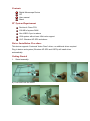
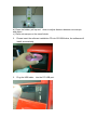
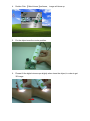
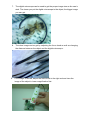
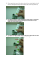
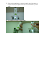
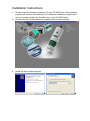
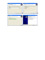
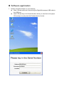
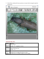
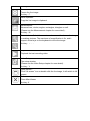
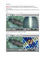
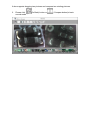
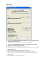
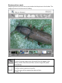
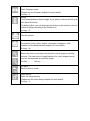
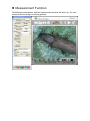
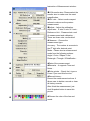
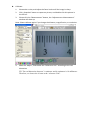
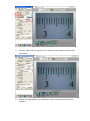
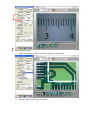
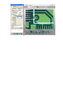
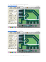
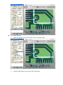
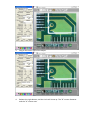
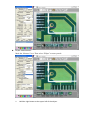
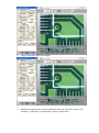
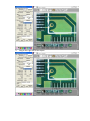
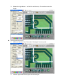
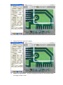
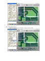
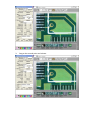
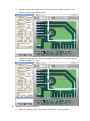
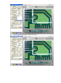
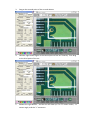
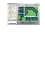
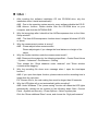
Contents Product Feature/Specifications……………………………………………………1 Contents……………………………………………………………………………..2 PC System Requirements…………………………………………………………2 Driver installation Procedure………………………………………………………2 Getting Started………………………………………………………………………2 Application Software………………………………………………………………..6 Install………………………………………………………………………………6 Software application……………………………………………………………..7 Function Key Lists………………………………………………………………..8 Compare…………………………………………………………………………..9 Video Setup………………………………………………………………………10 Preview picture mode……………………………………………………………11 Measurement Function………………………………………………………….12 Q & A………………………………………………………………………………….15 200X Digital Microscope/500X Digital Microscope Features The 200X digital microscope provides 10~200X adjustable magnification range, and 500X microscope provides 500X magnification. The build-in high-performance white LED can illuminate the object without using any auxiliary light. Adjust focus knob on the flank, the magnified image can be seen, captured and recorded from computer screen with VGA (640x480) & SXGA (1280X1024) resolution directly. Specifications Image Sensor: Effective Pixels: Signal Output: 1/4” Color CMOS image sensor 1280 (H) x 1024 (V) pixels Serial data for USB standard compliant 2.0 Gain Control: White Balance: Snap Shot Mode: Power Source: Auto Gain Control (AGC) Automatic Hardware/Software controllable 5VDC through USB port Power Consumption: 110mA (AVG) O/S: Windows XP/ VISTA / Windows 7 Fixed magnification for 50X and 200X digital microscope: 10X~200X range CE, FCC and RoHS Compliant Applications Skin Check Scalp Check Industrial Inspection e.g. Printing Circuit Board(PCB)inspection, Electronics device inspection Visual Assistance Printing Inspection Textile Inspection Paper money Inspection Jewelry Inspection Science Learning Contents Digital Microscope Device CD User manual Stand PC System Requirement Pentium 4 Class CPU 128 MB of system RAM One USB 2.0 port or above VGA system with at least 16bit color support UVC: Windows XP SP2 and above Driver Installation Procedure This device supports “Universal Video Class” driver, no additional driver required. Plug in device and system (Windows XP SP2 and VISTA) will install driver automatically. Getting Started 1. Stand assembly: a.) Push and Lock the stand. b.) Press the holder, pull up and down to adjust distance between microscope and object. c.) Place microscope on the stand holder. 2. Please insert the software installation CD into CD-ROM drive, the software will install automatically. 3. Plug the USB cable into the PC USB port. 4. Double Click 【MicroViewer】software, 5. Put the object near the center position. 6. Please tilt the digital microscope slightly when close the object, in order to get 3D image. image will show up. 7. The digital microscope can be used to get the proper image size as the user’s wish. The closer you put the digital microscope to the object, the bigger image you can get. 8. 9. The clear image can be got by adjusting the focus knob as well as changing the distance between the object and the digital microscope . If the image is blurred, adjust the focus knob to the right end and view the image of the object in lower magnification first. 10. When magnify the image of the object, adjust the focus knob slightly to the left and move the digital microscope up and down until a clear image shows up. 11. If the object is lumpy or a higher magnification (bigger image) is unnecessary, lift the digital microscope a little bit and adjust the focus knob to the right slightly until a clear image shows up. 12. If the object is too dark or bright, adjust the light knob to get the light you need. Turn right to get brighter light and left to get darker light. 13. When use high magnification or observe the specific area of the object, we suggest user placing the digital microscope on the stand holder to get clear image. 14. Use hardware snap button to capture image. Installation Instructions 1. 2. Please insert the software installation CD into CD-ROM drive, the installation program will show up automatically.(If the software installation program didn’t show up, please double click QutoRun.exe in the CD-ROM folder) Please click MicroViewer button for installing MicroViewer software。 3. Install the MicroViewer program。 Software application 1. Double click MicroViewer on your desktop。 Note:1.Please make sure connecting the Digital Microscope USB cable to the USB port. Note:2.Please key in the Serial Number which you can find on the paper CD envelope or just press the Evaluate button for trial. 2. MicroViewer window will show up and you can see the live image through the Microscope. Function Key lists: Snapshot: Take a picture Hot key:F3、snapshot of device。 Record: Capture AVI video files. Hot key:F4。 Compare: Compare the live image with picture or video. (Please see the Compare chapter for more detail)。 Hot key:C。 Freeze: Freeze the live image. Hot key:F。 Save clipboard: Copy the live image to clipboard. Measurement: Measure lines, circles, angles, rectangles, triangles or radii. (Please see the Measurement chapter for more detail)。 Hot key:M Zoom in / out:Select the zoom-in and zoom-out function on live image or existing pictures. The maximum of magnification is 6x, and it support arrow keys on the keyboard to move the image. Hot key:+、- Play : Playback the last recording video. Video Setup: The setup window. (Please see the Video Setup chapter for more detail)。 Hot key:V Zoom screen: Click “full screen” icon or double click the live image, it will switch to full screen. Exit: Close MicroViewer Hot key: X Compare: Please click the Compare button, and the compare window will show up. Warning: To get better operation, the screen resolution requirement is at least 1440*900 pixel Live image shows in the left zone, and you can drag a picture in the list bar to right zone. It supports freeze function to compare two images. It also supports dragging two pictures and compare two existing pictures. 3. Please click normal mode。 (Go Back) button or (Compare button)to back Video Setup Click the Setup button, the following window will appear: Source:It allows user to choose the image source if there are more than one microscope connecting the PC. Video Format:It supports two options:640*480 or 1280*1024. Note: The Snapshot and Record format will be changed at the same time. Video Adjust:Change the Video values. AVI:Set up the video saving location and file name. Time Lapse:If you need time-lapse function, please check the box and select the time-lapse rate. BMP:Set up the picture saving location and file name. If you want to save JPEG files, please check the Save as JPEG box. Always On Top:If you check this box, the MicroViewer window is always on the top layer. Record On The Fly:Recording on the fly. Play On The Fly:Play the latest video automatically. Show Snapshot BMP:After snapshot, the preview window will appear. Use AVIDecompressor:Under some special computers, image zoom shows abnormal image. Please check this box to solve this problem. Video Renderer VMR:Please mark this box for most of computers. Use Intel 8xxG/9xxG VGA: Under some special computers with Intel chip, live zone shows abnormal image. Please mark this box to solve this problem. Full Screen mode:If the full screen mode box is checked, MicroViewer will start on full-screen mode automatically. 4:3:Live zone will keep in 4:3 aspect ration. This mode is suitable for measurement. FULL:The screen will be filled with live zone. Objects would be expanded possibly. ICON:The Screen will be filled with MicroViewer, and all function buttons will be kept. In this mode, image will be expanded and it is not suitable for measurement. Preview picture mode Drag the picture to the live zone or just double click the picture in the list bar. The Image will show in the live zone for editing. Drawing mode: Click the Drawing mode button, Microsoft Paint will appear. After editing, please close Microsoft Paint, and the image will update automatically. Save file: Click this button to save as a new file. New file name will be renamed by date and time. Hot key:S。 Compare: Enter Compare mode (Please see the Compare chapter for more detail)。 Hot key:C。 Delete: Click Delete button to delete image. If you want to recover this file, just click Save file button. For deleting files, you can also hold the picture in the list bar by the left button of mouse and drag to the Delete icon. Hot key:D。 Print file: Print the picture. Measurement: To measure lines, circles, angles, rectangles, triangles or radii. (Please see the Measurement chapter for more detail)。 Hot key:M Zoom in / out: Select the zoom-in and zoom-out function on live image or existing pictures. The maximum of magnification is 6x, and it support arrow keys on the keyboard to move the image. Hot key:+、-Hot key:+、- Go Back : Back to the live mode。 Video Setup: Enter the setup window. (Please see the Video Setup chapter for more detail)。 Hot key:V Measurement Function Click Measurement button, and the measurement window will show up. You can measure the live image or existing pictures. Instruction of Measurement window: VGA monitor size:Please select the rations to make sure the precise measurement. Adjust:Adjust the calibration。 Adjust axis:X axis /Y axis /X-Y axis。 Reference Unit:Please select a unit monitor size to make sure the exact magnification. H/V ratio:Select monitor aspect of measurement and calibration.。 There are three units: mm/inch/mil Measure:Choose the measurement type. Accuracy:The number is accurate to the 9th digit after decimal point. Mode:Please elect a measurement mode from the following options: Angle / Circle / Ellipse / Line / Rectangle / Triangle / 3DotsRadius。 Data of the measurement. Remarks:It supports Time and Notes。 Ruler guides:Check the L-type or Cross if you need this function. Record history: Record the measurement actions. It allows user to delete a record or clear all history records. After finish the measurement, just click Snapshot button to save this picture. Choose the color of the line and words. Calibrate: 1. Please take a ruler, and adjust the focus knob untill the image is sharp. 2. Click „Snapshot“ button to capture a picture, and double click this picture in the list bar. 3. Please click the “Measurement” button, the “Adjustment or Measurement” window will show up. Note: Please calibrate again if you change the distance, magnification, or resolution. 4. Mark the “Adjust”, and choose the “Reference Unit” according to the real dimension. EX: The real dimension between 3 centimeter and 4 centimeter is 10 millimeter. Therefore, we choose the 10 mm as the “reference Unit”. 5. Hold the right button at the point of 3 centimeter and drag to the point of 4 centimeter. 6. Release the right button, and calibration is done. Now you can proceed to measure. Angle Measurement: 1. Mark the “Measure” box. Then select “Angle” accuracy mode. 2. Hold the right button at the first point. 3. Drag to the left sight and release the right button. 4. Hold the right button and drag to the another side counterclockwise. 5. Release the right button, and the angle will show up. Circle measurement: 1. Mark the “Measure” box. Then select “Circle” accuracy mode. 2. Hold the right button at the upper left of the object. 3. Drag to the lower right of the object. 4. Release the right button, and the circle will show up. The “D” means diameter and the “A” means area. Ellipse measurement: Mark the “Measure” box. Then select “Ellipse” accuracy mode. 1. Hold the right button at the upper left of the object. 2. Drag to the lower right of the object. 3. Release the right button, and the ellipse will show up. The “D1” means X axis diameter, “D2”means Y axis diameter, and “A” means area. Line Measurement: Mark the “Measure” box. Then select “Line” accuracy mode. 1. Hold the right button at the left side of the object. 2. Drag to the right side of the object. 3. Release the right button,and the line will show up. The number means the length. Rectangle Measurement: 1. Mark the “Measure” box. Then select “Rectangle” accuracy mode。 2. Hold the right button at the upper left of the object. 3. Drag to the lower right of the object. 4. Release the right button,and the rectangle will show up. The number means the length x width = area. Triangle Measurement: 1. Mark the “Measure” box. Then select “Triangle” accuracy mode。 2. Hold the right button at the first point of the object. 3. Drag to the second point and release. 4. Hold the right button again at the second point of the object instantly. Then drag to the third point of the object. 5. Release the right button,and the Rectangle will show up. The number means the base x length / 2 = area. 3DotRadius/Arc Measurement: 1. Mark the “Measure” box. Then select “3DotRadius” accuracy mode 2. Hold the right button at the first point of the arc. 3. Drag to the second point of the arc and release. 4. Hold the right button again at the second point of the arc instantly. Then drag to the third point of the arc. 5. Release the right button,and the arc will show up. The “R” means radius , “A” means angle, and the “L” means arc. Q&A: 1. After inserting the software installation CD into CD-ROM drive, why the installation doesn’t install automatically? ANS:Due to the operation system security, many software disable the CD-R / 2. USB Autorun function. Please double click the CD-ROM drive on your computer, and click the AUTORUN.EXE. Why the image lags after I check the Use AVIDecompressor box on the Video Setup window? ANS:The Use AVIDecompressor function doesn’t support Windows XP SP3 3. or above. Why the measurement number is wrong? ANS:Please adjust before measurement. 4. Please adjust again if you change the focal distance or height of the object. Why the monitor twinkles under the measurement mode? ANS: Please set the system by the following steps:Start→Control Panel Home →System→Advanced→Performance→Setting 5. 6. Then release the “Show shadows under windows” and ”Show window contents while dragging.” Why the recording file show error message when I open the time-lapse function? ANS: If you open time-lapse function, please make sure the recording time is longer than the ratio time. EX: Choose 60s:1s, the real cording time must be longer than 60 seconds. Why the LED lights will go out automatically while recording? ANS: Under Windows 7, the “power saving” function will cease the LED lights automatically, please set the system by the following steps: Start→Control Panel→System and Security→Power Options→Select a power plan Click the “Show additional Plans” arrow, and choose the “High performance.”