1
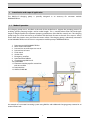
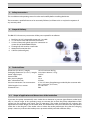
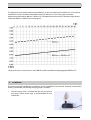
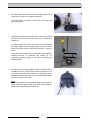
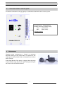
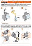
RAINMASTER Eco-LP
Installation and user manual
WATER, WE ´RE IN OUR ELEMENT
www.intewa.com
Table of contents
1 Introduction and scope of application ........................................................................................................................................ 2 1.1 Mode of operation ................................................................................................................................................................... 2 2 Safety instructions .............................................................................................................................................................................. 3 3 Scope of delivery ................................................................................................................................................................................ 3 4 Technical Data ..................................................................................................................................................................................... 3 4.1 Scope of application and dimensions of the intake line ............................................................................................. 3 5 Installation ............................................................................................................................................................................................ 4 5.1 Connection to basic control system .................................................................................................................................. 6 6 Maintenance ........................................................................................................................................................................................ 6 7 Guarantee.............................................................................................................................................................................................. 7 8 Contact ................................................................................................................................................................................................... 7 1
1
Introduction and scope of application
The RM Eco-LP charging pump is specially designed as an accessory for rainwater module
RAINMASTER Eco.
1.1 Mode of operation
The charging pump unit is installed at the end of the intake line to support the pumping process by
enabling greater pumping heights and/or intake lengths. This is needed when either the intake pipe
length or height exceeds the optimum pumping specification of the RM-Eco control unit. The charging
pump hangs on a float and moves up and down with the level of water in the tank. Thus water is always
drawn from the cleanest area, just below the water surface. The charging pump is electrically connected
to the RAINMASTER Eco unit and runs in conjunction with the pump in RAINMASTER Eco.
1.
2.
3.
4.
5.
6.
7.
8.
9.
10.
11.
Rainwater module RAINMASTER Eco
Mains water connection
Pressure line set with expansion vessel
Pressure line to house
Float switch
Suction line
Emergency overflow
Rainwater filter PURAIN
Charging pump RM Eco-LP
Quiet inflow
Protective conduit pipe for suction line
and sensor cable
12. Rainwater line
13. Wall bush MD100
An example of a rainwater harvesting system using RM Eco with additional charging pump situated in an
external water tank
2
2
Safety instructions
This installation and operating manual is to be read carefully before installing the device.
The instructions specified here are to be accurately followed, as failure to do so may lead to rejection of
any warranty claim.
3
Scope of delivery
The RM-ECO-LP accessory set contains all the parts required for installation.
1. Brushless 24 V DC submersible pump incl. 5 m cable
2. ½“ non-return valve with Ø14 mm hose sleeve
3. 2/3 hose sleeve with gland screws for connection to
suction line of the RAINMASTER Eco
4. Floating ball with stainless steel hooks
5. Waterproof connection box
6. Cable tie (without figure)
4
Technical Data
Dimension (H x W x D) / weight:
Packaging dimensions (L x B x T) / weight:
Power supply input:
Power intake:
Max. pressure height:
Max. volume flow rate:
Pressure connection / hose connection:
Cable length x Cross section:
Protection class:
125 x 57 x 83 mm / 0.6 kg
310 x 220 x 160 mm / 1.5 kg
24 V DC
20 W
3.2 m
25 l/min
½“ AG / Ø 14mm (lengthening provided by the customer with
min. 2 x 0,5 mm², Ø 5-7 mm)
5 m x Ø 5 mm
IP68
4.1 Scope of application and dimensions of the intake line
In practice, the pump automatically starts intake due to decrease in pressure (pipe friction, intake level)
only in a certain range. In this operating range, it evacuates the air from the pump independent of the
suction line (for example, with initial start up operation). The intake characteristic line indicates the
dependence of intake length on the intake level. The determined value must be above the represented
intake line in the diagram. If the intake value is below the intake performance line, then the charging
pump is necessary to ensure the intake process proceeds reliably and with sufficient safety.
3
The pump boosts the intake performance of RM Eco, so that an intake level of additional 3 m can now be
attained. This means that the intake performance line shifts down 3 m on the graph (see intake
performance characteristic RM Eco + RM Eco-LP). The determined value must be above the represented
intake line (RM Eco + RM Eco-LP) in the diagram.
Intake performance characteristics of the RM Eco with and without charging pump RM Eco-LP
5
Installation
The suction end of the intake line is installed as shown in the RM Eco user manual. However, instead of the
floating suction filter, the floating charging pump is installed.
1. The non-return valve is screwed into the pressure port of
the pump. Teflon thread tape is recommended for this
connection.
4
2. Push hose onto the nozzle and fasten it tightly with a hose
clamp (This must be an air tight connection.)
Fix floating ball via stainless steel hooks to the pressure
port of the pump.
3. The bottom of the booster pump must stand at least 20cm
off the bottom of the tank floor to ensure no sediment is
sucked up.
A safety distance of at least 10 cm must be set between
the upper edge of the charging pump and the bottom
edge of the float switch to ensure the pump is always in
water.
The pump cable is fixed to the suction pipe with cable ties
(without tension) to minimize the chance of any
component getting caught in the cable (especially the
floating switch).
>10 cm
>20 cm
4. The wiring is fed via the supplied connection box, which is
installed in the top of the tank near the inspection lid. (at
least 20 cm above the max. water level). The pump cable is
extended towards the house using an intermediate socket
(min. 2 x 0.75 mm2, Ø 5-7mm).
Note:
Kindly pay attention to the polarity while connecting the
power cable! The upper cable entry hole (not-required) is
sealed with a dummy plug at the factory.
5
5.1 Connection to basic control system
The electric connection to charging pump is established at the RM Eco basic control system.
Pressure pump + Charging pump
(Double occupancy of pump clamp)
-
+24 V
GND
(red / brown)
(black / blue)
!! Check polarity !!
6
Maintenance
Charging pump maintenance is limited to minimum
biannual cleaning of the suction filter. To achieve this, the
intake grid is removed (click lock) and cleaned from inside as
well as outside.
If the wheel blower of the pump is clogged, then the pump
may be flushed using the pressure port. During flushing the
non-return valve should be removed.
6
7
Guarantee
INTEWA GmbH guarantees this unit for 24 months from the date of purchase. Kindly keep the sales receipt
as proof of this date.
Within the guarantee period, INTEWA GmbH reserves the right to either repair or replace faulty parts at its
own discretion.
The warranty does not cover any damage due to improper use, wear and tear, or intervention by third
parties. The warranty does not cover any defects which may only minutely affect the value or usability of
the device.
8
Contact
For customers in Germany:
For any queries, ordering of spare parts, as well as in case of service, kindly contact INTEWA GmbH directly,
quoting your product‘s model and identification numbers and the purchase invoice details, at:
INTEWA GmbH
Jülicher Straße 336
52070 Aachen
Tel.: 0049-241-96605-0
Fax: 0049-241-96605-10
Email: [email protected]
Internet: www.intewa.de
For customers in other countries:
For any queries, ordering of spare parts, as well as in case of service, kindly contact your installer or the
authorised importer, quoting your product‘s model and the purchase invoice details.
ENJOY YOUR RAINMASTER ECO and the savings you will make for your pocket and the planet!
7
© INTEWA GmbH
Version: 1.0c
Subject to technical changes.
8