1
Chapter 1: Introduction
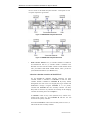
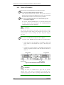
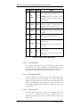
over a VT-100 terminal emulation program running on a
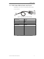
management computer. An audio-jack to DB9 cable for the
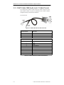
MAGELLAN or a dual-audio-jacks-to-DB9 Y-cable for the
MAGELLAN was shipped with your subsystem to facilitate the
connection. Use the cable to connect the COM1 serial port to a PC
hyper-terminal for terminal emulation management.
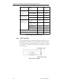
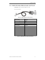
The second COM port, marked as COM2, is for connecting to an
uninterruptible power supply (UPS). An optional audio-jack-toDB9 cable (PN: IFT-9270CUPSCab) is available for purchase.
Please refer to Appendix A for instructions on connecting a UPS.
•
a
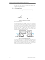
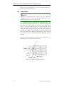
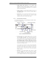
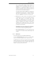
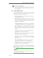
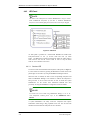
Ethernet port: All controller modules on the MAGELLAN come with
10/100M Ethernet port used for remote management through the
network. When operated in the dual-active mode, system
configuration is handled through one of the controllers. In the
event one controller fails, the Ethernet port on the other controller
inherits the configured IP and continues the monitoring or
configuration service. Shielded cables must be used to protect
against emissions. Connect the other end of the Ethernet cable to a
LAN hub port of the local network.
1.3.6.2
•
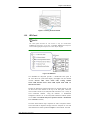
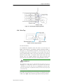
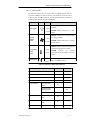
LED indicators: Each controller board rear panel comes with six
(6) LED indicators. Please refer to Chapter 4 for information on
how to monitor your subsystem using these LED indicators.
•
Restore Default Button/LED: Press the restore default button until
the LED is lit on will restore all factory default settings to the
controller.
DIMM Module
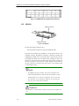
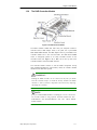
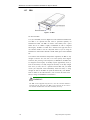
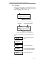
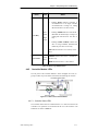
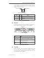
Each controller module comes with a DDR RAM DIMM module.
The 184-pin DDR RAM DIMM socket comes with a pre-installed 512MB
capacity or above DDR RAM DIMM and is able to support up to 2GB.
The DIMM module can be found on the controller board. When the DIMM
module is being changed, the controller module must be disassembled and
the controller board removed from the controller module. Please see
Chapter 5 for upgrading/replacing DIMM modules.
Major Subsystem Components
1-13