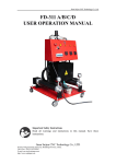
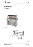
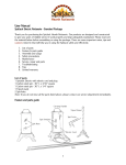
1
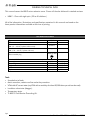
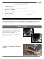
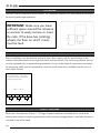
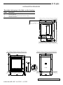
INSTALLATION MANUAL
HR8+HR8 P Solid Back
MODELS
Programmable controls HR8P
Model HR8+HR8 P
- NOTICE This manual is prepared for the use of trained Service Technicians and
should not be used by those not properly qualified. If you have attended
a trianing for this product, you may be qualified to perform all the procedures in this manual.
This manual is not intended to be all encompassing. If you have not
attended a training for this product, you should read, in its entirety,
the repair procedure you wish to perform to determine if you have the
necessary tools, instruments and skills required to perform the procedure.
Procedures for which you do not have the necessary tools, instruments
and skills should be performed by a trained technician.
Reproduction or other use of this Manual, without the express written
consent of Fri-Jado, is prohibited.
WWW.FRIJADO.COM
Installation Manual HR8+HR8 P form 9123653 rev. 05/2007
Page 2
Installation Manual HR8+HR8 P form 9123653 rev. 05/2007
INDEX
Index ............................................................................................................................... 3
General technical data .................................................................................................... 4
Technical data ..................................................................................................................................4
Installation procedures .................................................................................................... 5
Unpacking the unit ...........................................................................................................................5
Removal of pallet ..............................................................................................................................5
Location ...........................................................................................................................................6
Electrical supply ................................................................................................................................6
Legs / castors ...................................................................................................................................6
Tethering of the unit ..........................................................................................................................7
Test run ............................................................................................................................................8
Extraction of the rotisserie..................................................................................................................8
Instructions for operators ...................................................................................................................8
Installation drawings ....................................................................................................... 9
Installation Manual HR8+HR8 P form 9123653 rev. 05/2007
Page 3
GENERAL TECHNICAL DATA
This manual covers the HR8 P series rotisserie ovens. Ovens will also be delivered in stacked versions.
• HR8 P – Oven with eight spits ( 32 to 40 chickens )
All of the information, illustrations and specifications contained in this manual are based on the
latest product information available at the time of printing.
TECHNICAL DATA
Type
Power
Fuses needed with power connection
208 V, 3 ~ 60 Hz (3 phases without zero)
HR8 P
10500W
3x 35 A
Fuses needed with power connection
208 V, 1N ~ 60 Hz (1 phase with zero)
Recommended plug
_
NEMA 15-50P
G
Z
X
Y
Stacked HR8 P cabinets: each cabinet comes with separate power cord!!
Net weight
399 lbs.
Gross weight
478 lbs.
Height
40”
Width
38 13/16”
Depth
33 1/2”
181 kg
217 kg
1015 mm
985 mm
850 mm
Tools
• Standard set of tools.
• Metric wrenches, sockets and hex socket key wrenches.
• VOM with AC current tester (any VOM with a sensitivity of at least 20,000 ohms per volt can be used).
• Insulation value tester (Megger).
• Temperature tester.
• TL 84919 Field Service Grounding Kit.
Page 4
Installation Manual HR8+HR8 P form 9123653 rev. 05/2007
INSTALLATION PROCEDURES
•
•
•
•
•
•
•
•
Unpacking of the unit.
Remove the pallet under the unit with the help of a fork lift.
Put the unit on his location.
Check if there is enough free space around the unit (see installation drawing).
Check the electrical supply.
Tethering of the unit.
Load a program in the memory and make a test run on 250°C (482°F).
Give instructions to the operator.
UNPACKING THE UNIT
Immediately after unpacking the oven, check for possible shipping damage. If the oven is found to
be damaged, save the packaging material and contact the carrier within 15 days of delivery.
REMOVAL OF PALLET
The standard way to remove the rotisserie from
a pallet is with a fork lift. See pictures. Open
door and remove the drawer. Lift the unit from
pallet and put the unit in its place.
Note: when lifting a stacked unit, always use the
drawer of the bottom unit.
Another possibility is to disassemble the pallet.
For the pallet of the HR8 follow the procedure on
the photo.
Installation Manual HR8+HR8 P form 9123653 rev. 05/2007
HR8
HR8+HR8
Page 5
LOCATION
The oven must be installed on a level surface. The installation location must allow adequate clearances
for servicing and proper operation.
IMPORTANT: Make sure you leave
sufficient space around the rotisserie
or warmer to easily remove or insert
the rotor. If the base has (rotating)
wheels, the floor on which it rests
must be level.
27 1/2”
ELECTRICAL SUPPLY
Prior to installation, test the electrical service to assure that it agrees with the specifications on the
machine data plate located on the right side panel near the controls. The connecting cable for the unit
must be equipped with an approved plug connection. If use is to be made of a permanent connection,
the connecting cable must be connected to a manual on/off switch that is installed near the unit in a
clear visible manner.
For a 3-phase 208 V ~ circuit without
neutral, the unit must be connected according to the figure below.
208 V, 3 ~ 60 Hz
1
2
L1
3
4
L2
5
6
L3
LEGS / CASTORS
Each oven is furnished on 40 mm (1 1/2” legs). Stacked models are furnished with 2 swivel and 2
locking swivel castors. A castor-equipped stand with convenient storage drawer is available; the oven is
mounted on top of the stand.
Page 6
Installation Manual HR8+HR8 P form 9123653 rev. 05/2007
TETHERING OF THE UNIT
(For model HR 8 P units for fixed wiring and stacked or placed on bases with casters)
Warning: Safety standards require that, when this appliance is properly connected to the electrical
power supply using flexible conduit, adequate means be provided to limit movement of the appliance
without depending on or transmitting stress to the electrical conduit. This means that, as part of the
installation, the base or bottom unit of stacked models must be secured to the building structure (typically either wall or floor) to limit the movement of the appliance and, thus, helping to
prevent damage to the conduit during cleaning, maintenance and service operations.
A tether bracket, as shown on the drawing below, is provided with the base or stacking kit. Based on
the routing of the flexible conduit, the bracket must be installed along with the caster to one corner of
the base using the hardware provided. The remaining open hole in the center of the tether bracket is to
be used to secure one end of the tether (locally supplied chain, cable, etc.). The other end of the tether
is to be secured to an anchoring point in the building structure. Note: Length of tether must be shorter
than the flexible conduit to make sure that during appliance movement, no stress is transmitted to the
conduit.
Warning: Following installation, check to confirm that, when the appliance is moved to the limits of the
tether in each direction, no stress is transmitted to the electrical conduit.
Installation Manual HR8+HR8 P form 9123653 rev. 05/2007
Page 7
TEST RUN
The oven must be burned in to release any odours that might result from heating the new oven surfaces. Operate the oven at maximum temperature setting of 250°C (482°F) for 30 minutes. Smoke with
an unplaesant odour will normally be given off during this burn-in period.
EXTRACTION OF THE ROTISSERIE
Although an extraction hood is not prescribed, it could be desired that a hood is placed over the rotisserie. The HR8+HR8 produces about 20 m3 (700 cf) water vapor. When placing the rotisserie under
an extraction hood you have to consider the following guide lines:
- The minimum capacity of the extraction hood has to be 1700 m3/h (1000 cfm)
- The extraction hood has to extend minimum by 20 cm (8”) on all sides of the rotisserie
- The extraction hood has to have a free hight, above the rotisserie, of a minimum of 30 cm (12”)
- The rotisserie has to be accessible for service purposes
INSTRUCTIONS FOR OPERATORS
After installation of the rotisserie or warmer, the operator of the unit has to be instructed.
The instruction has to cover the following subjects:
•
•
•
•
•
•
•
Page 8
Programming and options.
Working of the unit.
Free space of unit for cooling of drive motor and blowers.
Run through the user manual.
Refer to the storyboard, training guide and laminated sheet with pre-programmed programs
(only for Wall-mart).
Periodical maintenance:
o
Cleaning of fan plate every month.
o
Cleaning of fans on blower every month.
How to react for information or service calls.
Installation Manual HR8+HR8 P form 9123653 rev. 05/2007
INSTALLATION DRAWINGS
Description belonging to the lables on the drawings
Label
1
2
3
4
Description
Power cable, length 1.8m (70”)*
Exhaust opening
Space between a rotisserie and a wall or ceiling
Location for socket
*) length is measured from the point where the cables coms out of the unit
Placing and connecting the HR8 Solid Back
Installation Manual HR8+HR8 P form 9123653 rev. 05/2007
Page 9
Placing and connecting the HR8+HR8 P Solid Back
Page 10
Installation Manual HR8+HR8 P form 9123653 rev. 05/2007
Placing and connecting the HR8 P on base
Installation Manual HR8+HR8 P form 9123653 rev. 05/2007
Page 11
Placing and connecting the HR8 P Solid Back
Page 12
Installation Manual HR8+HR8 P form 9123653 rev. 05/2007
Placing and connecting the HR8+HR8 P Solid Back
Installation Manual HR8+HR8 P form 9123653 rev. 05/2007
Page 13
Placing and connecting the HR8 P Solid Back on base
Page 14
Installation Manual HR8+HR8 P form 9123653 rev. 05/2007
Installation Manual HR8+HR8 P form 9123653 rev. 05/2007
Page 15
Fri-Jado Inc. • 180 Kehoe Blvd. • Carol Stream, Ill. 60188 • USA • toll free 877-FRI-JADO • [email protected] • www.frijado.com
Page 16
Installation Manual HR8+HR8 P form 9123653 rev. 05/2007