1
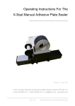
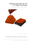
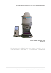
Operating Instructions For The
X-Seal AAS
Automated Adhesive Sealer
__________________________________
Version 1 Release 1 November 2009
©FluidX Ltd.
FluidX Ltd. Monks Heath Hall, Chelford Road, Nether Alderley, Cheshire, SK10 4SY, UK.
T: +44(0) 1625 861 614 F: +44(0) 1625 861 615 E: [email protected] www.fluidx.co.uk
Page 1 of 35
Operating Instructions For Automated Adhesive Sealer
This document is for information only; the manufacturer accepts no liability for errors
contained herein or for incidental or consequential damages with the furnishing,
performance, or use of this material.
Unless otherwise specified references to names or parts is purely casual and has the purpose
of illustrating the product. The contents of this publication may not be reproduced in any
form or by any means (including electronic storage and retrieval or translation into a foreign
language) without prior agreement and written consent from the copyright owner.
The information contained in this document is subject to change without notice.
Page 2 of 35
Operating Instructions For Automated Adhesive Sealer
TABLE OF CONTENTS
1.
INTRODUCTION
4
2.
DIRECTIONS FOR USE
5
3.
HEALTH AND SAFETY
6
4.
CONNECTING AIR SUPPLY
9
5.
CONNECTING VOLTAGE SUPPLY
10
6.
SWITCHING ON THE SYSTEM
11
7.
FOIL OR FILM LOADING
12
8.
PLATE SUPPORTS
15
9.
INTERCHANGING THE ROLLER AND PRESSURE CONTROL
16
10.
FOIL / FILM POSITION & LENGTH
17
11.
OPERATION PROCEDURE AND OPTIMISATION
18
12.
FURTHER INFORMATION
21
13.
RECOMENDED SEALS
22
14.
COMMUNICATION PROTOCOL
23
15.
COMMANDS
27
16.
CLEANING
28
17.
SPECIFICATIONS
29
18.
MAINTENANCE
30
19.
FAULT FINDING
34
20.
DECLARATION OF CONFORMITY
35
Page 3 of 35
Operating Instructions For Automated Adhesive Sealer
1. INTRODUCTION
For your own personal safety please read this manual before operating the Automated
Adhesive Sealer.
The X-SEAL AAS System has been designed for robotic integration, offers a fast effective
solution for the cold roll sealing of microlitre plates for experimentation, storage or
transportation.
Cold plate sealing is rapidly becoming the new process for the effective sealing of 96, 384
and 1536 plates. The extensive range of sealing materials now available for our new
instrument give permanent or peelable high integrity seals for all plate material types. The
range includes ultra clear materials for colorimetric or fluorimetric assays, along with solvent
resistant seals with low temperature (-80°C) storage characteristics.
The new X-SEAL AAS has been designed for bench top mounting with clean lines, easy
access and operation. It features a serial port allowing RS232 communication for robotic
control plus a touch screen for manual operation. Seal process time and pressure is fully
adjustable with visual indication for operation fault and ‘low foil’ warning.
X-SEAL AAS can be as easily integrated into robotic platforms from all leading automation
companies.
Manufactured for:
Manufactured by:
fluidX Ltd.
Monks Heath Hall
Helford Road
Nether Alderley
Cheshire
SK10 4SY
UK
KBiosystems
5 to 10 Paycocke Close
Paycocke Road
Basildon
Essex
SS14 3HS
UK
Tel: +44 (0) 1625 861 614
Fax: +44 (0) 1625 861 615
Email: [email protected]
www.fluidx.co.uk
Page 4 of 35
Operating Instructions For Automated Adhesive Sealer
2. DIRECTIONS FOR USE
The unsealed plate is placed on a shuttle, which extends from the front of the sealer, allowing
full access with a robotic arm. The shuttle is drawn into the unit automatically and the plate
can be sealed in 12 seconds, depending on the plate, foil and roller pressures selected. The
shuttle then slides the sealed plate out, presenting the plate back to its original position.
The sealer, as part of a fully automated plate handling system, which can be controlled via a
PC using a RS232 communication protocol, Alternatively the X-SEAL AAS can be manually
operated as a stand alone unit using the built–in touch screen display.
Each roll of cold roll sealing foil/film is supplied with a backing sheet and is sufficient for appox
two thousand five hundred plates. The transfer platen cuts the foil to cover the entire plate
surface but does not permit any overhang down the side, which would affect the plates
handling, or the visibility of barcodes.
The foil can be trimmed to fit the exact length of the plate, or have a ‘tab’ to assist with foil
removal, when required. The rolls of sealing foil/film are either aluminium or clear laminates
and are able to produce permanent, pierceable or peelable seals with Polypropylene,
Polystyrene or Polythene Microwell plates.
To keep the size and weight to a minimum, the unit uses clear and dry compressed air and all
parameters, such as time and pressure are fully adjustable to ensure a perfect, even seal with
different plate and film formats.
User safety has been carefully considered during the design process, to eliminate risk of
contact with moving parts of the internal mechanism during operation.
Page 5 of 35
Operating Instructions For Automated Adhesive Sealer
3. HEALTH AND SAFETY
It is Important that the X-SEAL AAS is installed and operated in such a way that
all applicable Heath and Safety requirements are met. It is the user’s
responsibility to ensure that all relevant Health and Safety Regulations are
identified and complied with. Failure to do so, may result in damage to the
equipment and could cause personal injury.
In particular, the user should study the contents of this guide carefully before
handling or operating this equipment.
Under no circumstances will the supplier of this equipment be liable for any
incidental, consequential or any special damages of any kind whatsoever,
including but not limited to lost profits arising from, or in anyway connected
with the use of this equipment or this instruction manual.
Warnings
Do not operate this instrument in an atmosphere containing explosive gases.
Only approved, supplied mains cord must be used with this instrument. If an extension
lead is required, the lead MUST be earthed.
Safety guards MUST be used at ALL times during the operation of the unit.
Always remove the sealing film before transporting the sealer.
The unit should only be used in a suitably ventilated area. The use of solvents on the
unit is not recommended.
Certain components become hot during the correct operation of the equipment.
These are marked as below. Due care should be taken to avoid personal injury.
Disconnect air supply and electrical supply before removing safety guards.
Warning symbols
Risk of electric shock.
!
Moving equipment.
Earth protective conductor.
Page 6 of 35
Operating Instructions For Automated Adhesive Sealer
Operating conditions
Temperature Range:
Operating 15º C to 40º C
Storage 0º C to 40º C
Relative Humidity:
Operating 10% to 80% Non-condensing
Storage 10% to 80% Non-condensing
Voltage:
The Automated Thermal Sealer is supplied for direct connection
to normal 115VAC or 240VAC supply, with a variation of 108VAC
to 250VAC.
The following fuses are fitted to the Automated Thermal Sealer:
Supply
230VAC
115VAC
Fuses Fitted in Plug
13 Ampere
No Fuses
Fuses Fitted in Sealer
T5AH 250V
T5AH 250V
Only refit the correct type of fuse. Must be IEC127 approved for use in EC Countries.
Must be C.S.A. or UL listed or recognised for use in Canada or the United States of America.
Operate the Automated Thermal Sealer in a draught-free environment to help maintain
temperature stability. The time between cycles may increase if sealing plate cools.
Place the unit on a secure bench to avoid movement during use. Allow 170mm at the front of
the instrument for operation of the plate carrier.
The X-SEAL AAS should be only operated in an environment with a temperature range of 15°C
- 40°C and a non-condensing relative humidity range of 10% - 80% . The unit should be kept
out of draughts and air currents as they will have an adverse effect on the temperature
stability of the sealing platen.
The machine should be mounted on a sturdy bench to avoid any bounce during operation.
When locating the machine there should enough space allowed for the shuttle to extend
without hitting anything or anybody. The reduced weight makes the X-SEAL AAS much easier
to move into a suitable position.
Page 7 of 35
Operating Instructions For Automated Adhesive Sealer
Operating conditions
Shown below is the main control PCB showing the fuse position and layout.
All fuses used upon this unit are T rated (Time lag) and H (High Breaking Capacity)
1 Amp Fuse
Page 8 of 35
Operating Instructions For Automated Adhesive Sealer
4. CONNECTING AIR SUPPLY
All electrical and pneumatic connections are made to the lower rear of the unit (Fig. 6). This is
the only point of interconnection.
UK Europe and Asia supplied units.
The unit is supplied with a 6mm push-in connector to fit into the 1/4 BSP inlet.
USA supplied units.
The unit is supplied with a 1/4 inch push-in connector to fit into the Filter Regulator input.
When fitting an air connector to the Automated Thermal sealer prevent the bulkhead fitting
from turning while tightening the connector to prevent loosening.
Air supply should be 80psi (5.5 bar) / 87psi (6 bar) max.
Provide 50 litres/minute through a pressure regulator as there is no air regulation of the air
within the instrument.
NOTE
Exceeding the maximum pressure may damage the unit. The air supplied must be clean, dry
and oil-free. Most air regulators include a water filter but not an oil filter; this may need to be
fitted separately.
Fig. 6
The air supply for the X-SEAL AAS should be 80psi ( 5.5 bar ) and a maximum of 87psi ( 6 bar ).
The supply should be able to provide 50 litres/minute through a pressure regulator as there is
no regulation of the air within the X-SEAL AAS. Exceeding the maximum pressure may
damage the unit. The air supplied must be clean, dry and oil-free. Most air regulators include
a water filter but not an oil filter; this may need to be fitted separately.
Page 9 of 35
Operating Instructions For Automated Adhesive Sealer
5. CONNECTING VOLTAGE SUPPLY
The Automated Thermal Sealer utilizes a standard IEC inlet, which is fused and switched.
Plug the IEC lead in the inlet and switch on the rocker I.O. switch (Fig. 7). The display mounted
on the front of the unit should illuminate.
NOTE
The system is self regulated to sense voltage differences between 100 and 240 VAC.
Fig. 7
NOTE:
If the X-SEAL AAS. Fails to power up when correctly connected, then check the external fuse
at the rear of the machine – see above photo. If this fuse has failed then a replacement 5A
anti-surge fuse is included with machine. If this fuse is intact then an internal fuse may have
failed. Either contact ABgene® or your distributor before removing the main cover. The photo
above shows the location of the fuse that may have blown. It is a 1A anti-surge fuse and 2
replacements are provided with the machine.
Also check that the E-Stop is in its operational position i.e. fully out.
Page 10 of 35
Operating Instructions For Automated Adhesive Sealer
6. SWITCHING ON THE SYSTEM
When the power is successfully connected to the
sealer, the touch screen display will light up and the
display will be as Display 1.
Display 1
The unit will sound three times whilst the system
starts and the display will change to as shown in
Display 2.
Display 2
The next screen then waits for the proceed area of
the screen to be touched.
Display 3
After proceed has been touched, the initialising
screen is displayed and remains until the shuttle
homes into the sealer and returns to the preset plate
loading position.
Display 4
Page 11 of 35
Operating Instructions For Automated Adhesive Sealer
The next screen gives the option to proceed with
the sealing action or go into the set up choice
area. The correct plate length and number of rolls
can be checked to that displayed. Ensure that the
correct plate and carrier are loaded onto the
shuttle prior to sealing. The set up will take into the
multi-choice screen to select the option required.
Display 4
7. FOIL OR FILM LOADING
To load the foil/film. When starting from new, or after using the reel for some time, the low film
alarm will indicate that a new foil or film reel needs to be loaded.
When this alarm is displayed during use, it indicates that the foil or film roll has only a certain
number of seals left available from the loaded roll. The number of seals left after the alarm
appears is variable through the position of the foil sensor and normally factory set to that
stated in the original specification.
The next screen is displayed whilst the sealer sets
itself to the foil loading condition. This requires that
the cutter is raised clear of the foil area and that all
moving parts are homed.
Display
6
Display 7
Once this screen is displayed, the sealer must then
be switched off prior to the foil/film reel being
loaded. The display will then go blank and the air
will be vented and isolated.
See later parts of this chapter 8 for details on how to
load the foil/film
Display 8
After the procedure for loading the foil/film has
been completed and the doors all closed with
power and air reapplied, the sealer can then be
switched back on. The start-up displays all appear
as already defined, and then display 8 waits for
confirmation that the service door has been
opened and the foil off cut removed. The service
door opening will cause the air to be evacuated,
this will be restored once the door is closed and
locked shut. Display 5 is then shown ready to
continue.
Display 9
Page 12 of 35
Operating Instructions For Automated Adhesive Sealer
Always ensure that sufficient room is made around the side cover area to permit easy access
for loading the foil, installing the blank foil backing spool and for threading the foil through the
guide rollers and into the cutter.
The mains and air supply must be connected to load the foil. The screen offers a foil load
option to ensure that the internal mechanism is moved to the default locations. The cutter is
powered to the up position, ready for the foil loading. When the side cover is removed the
interlock mechanism immediately exhausts all of the air within the instrument and allows the
foil to be placed through the open punch/die and foil clamp assembly, to allow the film and
backing to be threaded through the system.
Both foil and backing spindles that contain the roll of film are fitted with manually adjustable
clutch mechanisms.
The side cover is removed by first undoing the two retaining knobs and the side cover can
then be carefully removed outwards. This action will immediately cause the internal air supply
to be cut off - an air discharge will be heard and this is normal.
Care should be taken with the side cover since the control interlock mechanism on the side
cover is now exposed and could cause injury or damage. The two fixing knobs should also be
safely stowed for later reuse after foil loading is complete.
A diagram is located on the side of the unit detailing the path of the foil and backing film.
The top spindle holds the full or part full reels of foil or film. This is loaded onto the spool that fits
the top spindle. This spool has a smaller spindle hole (18mm) and the red spool-locking ring
has a left hand thread. After clamping the foil securely and fitting to the top spindle, taking
care to have the foil fitted onto the spool he right way round – see diagram for rotation
direction, the white inner washer (18mm bore), the spring, the outer metal washer (18mm
bore) and the knurled clutch adjusting nut (18mm LH) should be screwed half way onto this
shaft (LH).
An empty reel core should then be firmly fitted to the second spool. This spool has a 20mm
bore and 20mm clutch components and should be fitted to the lower spindle, similar to the
procedure for the top spool. The knurled nut should then be screwed on to about half way
(RH).
The foil end and backing should then be unfastened and passed under the central fixed
guide roller and towards the cutter area, but over the horizontal flat platen. The backing
Page 13 of 35
Operating Instructions For Automated Adhesive Sealer
should then be peeled away from the foil or film and passed down between the rounded
end of the platen and the rear of the cutter
block. As the backing is pulled down and around the lower fixed spool, the foil or film should
be fed through and over the open cutter block.
Extreme care should be exercised when in the cutter area since sharp surfaces are present
and accessible. The cutter itself is retracted 100mm above the cutter block and since the air
has been evacuated and isolated, the cutter can only slowly lower through gravity and so
should impose no real risk other than keeping clear of the very sharp edges.
After feeding the foil or film through the cutter, the backing can be then pulled around the
lower fixed guide and onto the empty reel core already fitted to the lower bobbin. This will
need to be secured centrally to the core using sticky tape. See the diagram printed on the
side of the X-SEAL AAS. for the exact foil and backing route and direction.
Once the backing has been secured and several turns made to start the reel off, the side
cover can be refitted, taking care with the protruding interlock mechanism, place the cover
on towards the main cover and located the interlock peg into the hole. After ensuring that
the peg is located properly and that the fixing studs have passed through the side cover, the
knobs can then be refitted. Over tightening of these knobs is not necessary.
The screen prompt should then be touched to start the final stage. This will permit the air back
into the system and lower the cutter to trim off the excess foil or film that has been previously
fed through the cutter whilst loading.
The front access door should now be carefully opened and lowered. This action will again
operate the safety system and evacuate the air from the X-SEAL AAS. Again this is normal.
Access to the off cut of the foil or film can then be gained to the right of the doorway. After
extracting the foil off cut, the door must be securely closed to continue. The internal air supply
will then be reconnected.
The final step is to make sure that the tension for both spools has been correctly set and that
the foil or film is feeding correctly. To ensure that the foil or film is presently correctly to the
transfer suction head, it is necessary to have the cut end of the foil or film tacked onto the
pads located under the cutter. The spool is then driven backwards by a motor and gearbox,
which gives the tension to present the foil or film flat and in line for the transfer suction head.
Too much tension (anti-clockwise) will break the hold at the tacked cut end-too little
(clockwise) and the foil will sag over he platen and so give no assistance to the suction
pickup. This could lead to either transfer failure or a wrinkled plate seal.
The lower spool is also driven but in the opposite direction to the top spool. This assists with
keeping the foil flat over the platen. The tension of the lower spool should be adjusted to take
up the surplus backing discharged from the end of the platen. Too much tension (clockwise)
will cause the foil or film to be pulled down over the cutter end of the platen, too little tension
(anti-clockwise) will prevent the lower spool from keeping pace with the backing discarded
and could result in the backing being pulled through the cutter. This will put undue stress on
the cutter block and should be avoided. Please note that the spool tension adjustments are
opposite to each other.
After becoming familiar with the foil or film installation procedure, the system can be quickly
loaded and operational, particularly if the same foil or film is being reloaded since the settings
already established may not need adjusting, as it is not necessary to remove the bobbins to
reload a new reel. Part used reels as well as full reels can be loaded onto the top bobbin.
However, care should be taken in loading non-empty cores to the lower bobbin since over
capacity will be detrimental to the clutch mechanism and the backing could become
unguided onto the bobbin. This could cause the backing to foul with other moving parts
within the X-SEAL AAS and cause plate sealing failure.
Page 14 of 35
Operating Instructions For Automated Adhesive Sealer
8. PLATE SUPPORTS
Plate supports are found in the spares kit provided and support the under side of the plate to
ensure that the seal is even across all the wells of the plate.
To select the correct plate support, measure the underside of the wells to the bottom skirt and
select a support which is slightly larger.
Page 15 of 35
Operating Instructions For Automated Adhesive Sealer
9. INTERCHANGING THE ROLLER AND PRESSURE CONTROL
The roller is located immediately behind the service door, located at the front of the
instrument. When the main door is carefully lowered and laid flat, the roller and fixings can
easily be seen and accessed. This will cause the interlock to exhaust the system air and isolate
the incoming air supply until the door is closed.
The roller assembly can be removed by undoing the three fixings with the supplied Allen key.
The yoke assembly can then be rotated through 90 degrees and lowered through the shuttle
opening.
The procedure to replace the roller is as above, taking care not to damage the roller and
that the yoke assembly is rotated in the correct direction to locate the yoke upper surface
with its mating part, attached to the cylinders. Prior to fitting ensure that the correct roller has
been selected and that the roller is free to rotate on its spindle. The locking screws at the rear
of the yoke should also be checked for tightness, since access to these is reduced once the
yoke assembly has been installed.
To achieve the correct sealing for different plates and foils or films, the
X-SEAL AAS
incorporates a manual adjustable pressure regulator and analogue gauge with a range of 04Bar (0-0.4Mpa). The pressure is initially set for about 1 bar and should suit most sealing
applications.
During operation, the gauge displays the pressure set for the roller. The roller pressure is
adjusted through a precision control located above the pressure gauge. These are both
secured into the main frame of the X-SEAL AAS and can be accessed only when the side
cover is removed. During operation, the gauge can be seen to operate during the rolling
operation. This pressure is manually adjusted using the knob. Rotating the knob clockwise (+)
will increase the pressure whilst rotating anti-clockwise will reduce the pressure (-). One full
turn of the knob is approximately equal to 1 Bar (14.5 PSI or 0.1 MPa), so by careful rotation,
the desired pressure can easily be assessed and set. The units are normally despatched with
the pressure set to 1 Bar.
As described above, to adjust the pressure it is necessary to remove the foil side cover.
Rotating and removing the two side facing knobs do this, will then permit the cover to be
carefully moved SIDEWAYS, to permit the safety interlock mechanism to disengage from the
main frame assembly. This will cause the interlock to exhaust the system air and isolate the
incoming air supply until the door is closed.
Adjustments in the pressure required for each set-up for variations in plate type, foil type and
roller type will quickly become familiar with use and often permit the correct set up to be set
at the first attempt. As with changing foils and having to adjust the spindle clutch pressures,
the more the operators become familiar with the instrument, the resulting set-up time will
become quicker.
To aid in roller selection, the different types have been colour coded. Each former for the
roller will be coloured to quickly identify the type of roller and its hardness.
A full reference chart will be found in the specification chapter within this manual.
Page 16 of 35
Operating Instructions For Automated Adhesive Sealer
10. FOIL / FILM POSITION & LENGTH
There is some limited adjustment available that can alter the position of the foil on the plate
and of the length of the cut foil. The fore and aft adjustment of the foil can be used to vary
the amount of overhang of the foil at the back an front of the plate. The side to side
adjustment can be used to place the foil so that the numbers on the plate are visible. The foil
length can be adjusted from a minimum to suit robotic piercing to a maximum to provide a
tab for peeling.
The adjustment of all these parameters is very similar in that the position stops that must be
adjusted are all of the same type. These stops have a threaded body that is M10 with a pitch
of 1mm so that one full turn of the stop will result in a change in position of 1mm. All of the
adjustments require the cover to be removed.
10.1 Foil length
The foil length is set at 125mm initially and may be adjusted to increase this by a maximum of
5mm each end. This standard factory setting of 125mm cannot be reduced; doing so may
cause the foil vacuum cups to become uncovered. To create a tab at the front of the plate
the stop at the rear of the fore and aft transfer must be adjusted and the same to create a
tab at the rear of the plate, the stop at the front of this transfer is to be adjusted.
Note: All adjusted positions are to be checked with cutter in the down position to ensure
against crashes
10.2 Side to side placement
The foil placement position may be changed by up to 5mm on each of the plate. To move
the foil further to the left, adjustments are to be made the left hand stop located on the top
of the transfer unit. The same is for moving the foil further to the right adjust the right hand
stop.
Page 17 of 35
Operating Instructions For Automated Adhesive Sealer
11. OPERATION PROCEDURE AND OPTIMISATION
The X-SEAL AAS System has been designed to reliably seal plates of different heights and
different plastics, using a variety of foils and films, to give a seal with varying properties. These
components will require different sealing conditions.
The quality and strength of the seal created between the sealing films will vary with different
conditions. In general, increasing either the sealing pressure or duration of seal, gives a
stronger, more complete seal. However over-sealing on a regular basis is not recommended,
as applying more pressure can cause damage to the plate being sealed. This in turn, would
reduce the number of times a particular plate can be resealed. Therefore a balance has to
be achieved, that gives an acceptable seal with the minimal plate damage or distortion.
Another optimisation factor to be taken into account is the surface area of the plate.
A plate with thin raised rims around each tube (chimney), will have a reduced surface area,
compared to a flat plate or with wide raised rims. This would mean that less pressure is
needed to seal the thin rim plate in comparison to the wide rim. The pressure that the roller
exerts during sealing is fully adjustable, as is the speed of travel for the shuttle.
From the set up on screen display 5, the choice
menu is displayed as shown on display 6. Selecting
the roll set up option will then display screen 10. This
allows for the pre-measured plate length to be set.
Pressing enter will then move onto the next screen.
Display 10
This next screen permits the number of foil/film rolls
to be set. Pressing enter will then move onto the
next screen.
Display 11
This next screen permits the exact position for the
shuttle out location. This sets the range of 235 to 275
units. Pressing enter will then move onto the next
screen.
Display 12
Page 18 of 35
Operating Instructions For Automated Adhesive Sealer
This next screen permits the choice for half or full
rolling. If yes is toggled, then the rolling procedure is
to roll from the centre of the plate to the back, raise
the roller and move back to the centre and then
roll from this position to the front. The roller then
stays down and the shuttle and plate move forward
so completing a final full length roll. Toggling for no
on the display eliminates the final full roll. Pressing
enter will then move onto the next screen.
Display 13
There is a facility to operate the machine remotely.
This screen permits the option to be selected by
toggling yes or no. Selecting yes will activate the RS
232 connector at the rear of the unit. Pressing enter
will then move onto screen 16 if the remote option
is not selected.
Display 14
If the RS232 option is selected, then screen display
15 becomes active. This allows for the RS232 option
to be de-selected by selecting the set up option on
this screen. This will then revert back to screen
display 14 where the no option can be toggled.
Again, pressing the enter area will move onto
screen display 16.
Display 15
The roll speed for the plate sealing is adjustable to
cater for the requirements of different rollers, plates
and foils/films. The adjustable range of 1 to 50
permits for the slow rolling requirements of some
films, typically crystallography which is set at
around 10, but this is normally set at 50 for fast
rolling. Pressing enter will then move onto the next
screen.
Display 16
To permit curing time for some foil/film glues after
they have been cut, a delay is selectable from 0 to
5 seconds to allow the exposed glue at the cut
edges to air dry and become less tacky. This
prevents any possibility of wrinkles being formed
during the plate sealing operation. Pressing enter
will then go back to screen display 6.
Display 17
Page 19 of 35
Operating Instructions For Automated Adhesive Sealer
This screen is displayed as shown in display 18. This is
similar to screen display 5, but defines that the
sealing operation has commenced and is always
displayed after screen 5.
Display 18
11.2 Commands, Indications and warnings.
The X-Seal System is software controlled, employing micro-controllers. All commands,
indications and warnings are affected via the touch sensitive LCD Display Panel located on
the front of the unit. The user-friendly menu regulates all operations. The Sequence of events is
as follows:11.3 Initiating Unit Operation.
Loading the machine with foil and triming the foil is described under section 8. The display is
used to set the sequence.
11.4 Foil low sensor
There is a sensor mounted below the spindle to provide a warning that the foil is running low.
As supplied the sensor is in the centre position of five possible positions. It may be adjusted up
or down to increase or decrease the amount of foil remaining when the warning is given.
11.5 Cover removal
All power and air connections must be removed prior to the removal of the cover. Should it
become necessary to remove the cover it is secured by three screws on one side and by two
on the other side. The small side cover over the foil roll also needs to be removed. To lift the
cover the foil spindles need not be removed or the clutch loosened as the cover can slide
behind the bobbins. The shuttle and service door are not part of the cover. These are
attached to the base unit. Once the cover has been lifted up so that it is clear of the power
and air inlet the ribbon cable connecting the display to the circuit board is revealed. This
must be disconnected before the cover can be removed completely. The cover should be
lifted at the back to ease it over the front of the machine. Replacing it is the reverse of
removal.
11.6 Internal fuse failure
If a voltage outside of the 100 to 240VAC is applied to the unit then the internal fuse will fail.
This is a 5A type F fuse and is installed into the built in fuse holder as part of the mains inlet
panel. This can be clearly seen in the adjacent inlet panel assembly pictures.
Page 20 of 35
Operating Instructions For Automated Adhesive Sealer
12. FURTHER INFORMATION
The amount of times a microplate can be sealed and resealed can be increased by
using the minimal amount of temperature and seal time to prevent chimney damage.
Sealed microplates that have been stored in a fridge or freezer do not always have to
be brought back to room temperature before peeling e.g. FluidX EZ Peel, a peelable
heat seal for polypropylene plates. (See the complete FluidX range for more
information).
FluidX has not yet tested seals from alternative suppliers and therefore is unable to
make recommendations regarding their usage at this time.
To prevent the risk of cross-contamination between wells when removing a peelable
seal, consider using one that can be pierced. Centrifuging before removal may also
be beneficial.
Page 21 of 35
Operating Instructions For Automated Adhesive Sealer
13. RECOMENDED SEALS
Heat Seal Rolls
40-1001
40-1002
40-1003
40-1004
40-1005
40-1006
40-1007
40-1008
40-1009
40-1010
40-1011
40-1012
43-1032
43-2032
Adhesive "Gold" Aluminium Sealing Foil (peeling). Good solvent
resistance, Temp range; minus 80°C to 120°C. 100m per roll (approx. 800
plates) for use with Xcs-384
Adhesive Aluminium Sealing Foil (piercing). Good solvent resistance,
Temp range; minus 80°C to 120°C. 100m per roll (approx. 800 plates) for
use with Xcs-384
Adhesive Polyolefin film (peeling). Micro-encapsulated solvent. Temp
range; minus 25°C to 120°C.100m per roll (approx. 800 plates) for use with
Xcs-384
Adhesive Polyolefin film, pre-pierced for good gas exchange, Temp
range; minus 25°C to 120°C. 100m per roll (approx. 800 plates) for use with
Xcs-384
Adhesive gas permeable membrane, impervious to fluids but provides
good gas exchange. 100m per roll (approx. 800 plates) for use with Xcs384. (81mm width, requires 45-1100 adapter)
Adhesive Polypropylene film (peeling). High solvent resistance. Temp
range minus 80°C to 120°C. 100m per roll (approx. 800 plates) for use with
Xcs-384
Adhesive Cristal Clear Polypropylene film (peeling). Solvent resistant.
Temp range minus 40°C to 120°C. 100m per roll (approx. 800 plates) for
use with Xcs-384
Adhesive PCR Film Roll (AB-2558) (100m) on 80mm backing, for use on
Abgene format sealer and XCS-384 (81mm width, requires 45-1100 kit).
Adhesive PCR Foil Roll (AB-2626) (200m), Abgene format sealer
Black PE Sealing foil, Peeling, light tight, good biological and solvent
resistance, Temperature range: -40°C to +60°C, for use with Xcs-384
Adhesive silicone foil, Piercable, high solvent resistance. Ideal for sealing
plates containing DMSO. 150M per roll, to seal approximately 1200 plates.
(81mm width, requires 45-1100 adapter)
Adhesive silicone foil, Peelable, high solvent resistance. Ideal for sealing
plates containing DMSO. 150M per roll, to seal approximately 1200 plates.
(81mm width, requires 45-1100 adapter)
QPCR adhesive clear seals (AB-1170), Optically clear for QPCR and other
fluorescence applications, (500m x 115.5mm), Peelable seal for PP and PS
plates, Velocity 11 format (41-1004 Equivalent)
QPCR adhesive clear seals (AB-1170), Sample Roll (25m), Optically clear
for QPCR and other fluorescence applications, (25m x 115.5mm),
Peelable seal for PP and PS plates, Velocity 11 format (41-1004 Equivalent)
Page 22 of 35
Operating Instructions For Automated Adhesive Sealer
14. COMMUNICATION PROTOCOL
Introduction
The 9 pin D type at the rear of the unit is labelled RS232 and is for connecting the X-Seal to a
PC using a serial port. The PC then uses the protocol detailed in section 13 to communicate
with the X-Seal This allows the sealing parameters to be programmed from the PC; enabling
the PC to request status information from the X-Seal; provides low foil and other warnings to
the PC.
Serial Port Set-up
9600---Baud rate
8 Data bits
No parity
1 Stop bit
No handshaking
All communications via Ascii.
Cable
PC (9 way female)
Pin 2
Pin 3
Pin 5
SEAL-IT 100™ (9 way female)
Pin 2
Pin 3
Pin 5
Message Response time
The unit responds to each message within 100 Millisecond.
Configuring for remote operation
On the touchscreen use the advanced menu to set the following:
When the system is powered up the operator is prompted to clear the plate load area before
the plate shuttle is extended.
“Mode” to “Rmt”.
This sets the unit into remote mode and ignores commands issued from the touch screen. This
is strongly recommended when controlling the unit from a host computer. Once unit has been
set to remote mode the unit must be restarted to allow remote control.
Page 23 of 35
Operating Instructions For Automated Adhesive Sealer
System Initialisation
Once unit has been restarted it must be initialised via the PC
PC sends
I<cr>
X-SEALreplies:
ok<cr>
Status Message
PC sends
?<cr>
X-SEALreplies:
<status byte><cr>
The status byte is a hexadecimal value represented in Ascii, ie the
characters "ff" means 0xff hex.
bit values:
bit 0
Low Air
bit 1
error
bit 2
Sealing
bit 3
Low air during seal
bit 4
Not initialised
bit 5
Low foil
bit 6
Door open/side cover missing
Begin Sealing Command
PC sends
S<cr>
X-Seal replies
ok<cr>
if the sealing operation has commenced
or
err<cr>
If it is unable to start the operation.
Page 24 of 35
Operating Instructions For Automated Adhesive Sealer
The seal it will not start sealing if the following conditions exist:
bit 0
low air
bit 1
error
bit 2
sealing
bit 3
low air during seal
bit 4
Not initialised
bit 5
low foil
bit 6
Door open/side cover missing
Error Message
PC sends
E<cr>
X-Seal replies
##<cr>
where ## is a decimal value represented in Ascii, ie the characters "01" means error 1.
Modify Seal Parameters
Note: Wait until unit is in idle state before modifying seal parameters.
PC sends
P%=###<cr>
X-Seal replies:
ok<cr>
where % is the parameter number and ### is the parameter value.
% is a single digit decimal number and ### is a 3 digit decimal number represented in Ascii
e.g.
The string P1= 127<cr> plate length to 127mm
The following parameters can be set
Page 25 of 35
Operating Instructions For Automated Adhesive Sealer
Parameter
1
Description
Plate length
Units
124mm to 128mm
2
Number of rolls
1 to 5
3
Shuttle roll position
235mm to 275mm
4
Full or half roll
5
Not used
6
Roll speed
7
Not used
8
Autosave
0= Full roll 1= Half roll
1 to 50
0=off 1=on
Note:- 1 = Low speed
50 = High speed
Reading X-Seal parameters
PC sends
P%<cr>
X-Seal replies:
###<cr>
where % is the parameter number and ### is the parameter value.
% is a single digit decimal number and ### is a 3 digit decimal number represented in Ascii
e.g.
To read the current plate length, send the string
P1<cr>
The X-Seal replies with the string
128<cr>
if the plate length is 128mm.
Manual Save Seal Parameters (Command R)
Normally Seal parameters are written to eeprom so that they can be saved through unit
power down. In some applications it may be necessary to turn autosave off (P8 = 0). This is
because the action of writing to eeprom may cause occasional corruption of
communications messages. If autosave is disabled then it is possible to save the sealing
parameters through power down using the R command.
Page 26 of 35
Operating Instructions For Automated Adhesive Sealer
15.COMMANDS
E<cr>
T<cr>
O<cr>
L<cr>
S<cr>
I<cr>
R<cr>
P1=128<cr>
P2=2<cr>
P3=256<cr>
P4=1<cr>
P5
P6=30<cr>
P7=2<cr>
P8=0<cr>
Error status
Trim
Open door
Lock
Seal
Initialise
Save Seal Parameters
Set plate length in mm
Set no of rolls
Set load position
Set roll type (0 = Full roll, 1 = Half roll)
Not used
Set roll speed to 30
Set cure delay to 2 seconds (1-5 seconds)
Set auto save of parameters on or off
P1<cr>
Query plate length, similar for all other p variables
?<cr> q
Query status
This will return an 8 bit hex number in ascii format.
Bit values:bit 0
Low Air
bit 1
error
bit 2
Sealing
bit 3
Low air during seal
bit 4
Not initialised
bit 5
Low foil
bit 6
Door open or side cover missing
bit 7
Not used
Page 27 of 35
Operating Instructions For Automated Adhesive Sealer
16. CLEANING
!
!
!
!
Before using any cleaning or decontamination method, other than that
recommended by the manufacturer, users should check with the
manufacturer that the proposed method will not damage the unit.
In case of radioactive spillage's, Advanced Biotechnologies Limited,
recommend that you use a proprietary cleaning agent and follow the
manufacturers instructions.
You may clean the X-Seal cover, with a cloth dipped in water or
ethanol, methanol or formaldehyde may also be used.
THE UNIT SHOULD NOT BE
IMMERSED IN SOLVENTS
DO NOT USE ACETONE OR
ABRASIVE CLEANERS.
Before using any cleaning or decontamination method, other than that recommended by
the manufacturer, users should check with the manufacturer that the proposed method will
not damage the unit.
Always remove the power and pneumatic supplies before cleaning the unit.
Do not turn on power and pneumatic supplies until the unit is fully dry.
DO NOT USE ACETONE OR ABRASIVE CLEANERS
Page 28 of 35
Operating Instructions For Automated Adhesive Sealer
17. SPECIFICATIONS
Power Supply:
Minimum 100VAC
Maximum 240V AC
Power Consumption:
150 Watts Nominal
Fuse Rating:
5 Amp anti-surge
Dimensions:
370 x 433 x 594mm
Weight:
28Kg
Air Input:
6mm or 1/4 “ BSP Female Thread
Air Requirement:
50 Litres per minute
Air Input Pressure:
5.5 Bar (80 PSI)
Minimum Operating Pressure:
5.5 Bar (80 PSI)
Minimum Operating
Ambient Temperature:
150C
Maximum Working
Temperature Ambient:
40oC
Minimum Sealing
Plate Height:
8mm
Maximum Sealing
Plate Height:
50mm
Protection:
IP20
Fire Retardancy:
Plastic Case & Trays ECCEN 6073
Cycle Time Minimum:
30 Seconds (Sealing Time Adjustable)
Access Panels Interlocked
Main cover, Side Cover & Service Door
Page 29 of 35
50/60Hz
50/60Hz
(W x H x D)
Operating Instructions For Automated Adhesive Sealer
18.MAINTENANCE
Lubricating and cleaning the cutter
The punch and die used in the SEAL-IT 100™ system needs regular lubrication to maintain the
quality of the cut of the sheets. Approximately every 2500 cuts (which is approximately after
every full roll or if the unit has not been operated for more than 7 days, the following
procedure should be carried out.
1. Set the system for as if it were in foil or film reel loading mode. This will raise the cutter
for easier access.
2. Remove the side cover. This will automatically evacuate the air within the system and
internally isolate the incoming air supply. Leave the mains voltage on.
Please ensure that all parts removed during maintenance are kept safe
3.
Apply a small quantity of the lubricating grease provided using a spatula or finger to
the rear of the heels of the die.
Page 30 of 35
Operating Instructions For Automated Adhesive Sealer
Rear View
4.
Open the service door.
Page 31 of 35
Operating Instructions For Automated Adhesive Sealer
6. Apply a small quantity of the lubricating grease provided using a spatula or finger to
the front of the heels of the die.
7. Close and secure the service door.
Page 32 of 35
Operating Instructions For Automated Adhesive Sealer
8. Replace the side panel and secure with the two knobs, Ensuring that safety plunger is
place correctly
9. Press ‘continue’ on the touch screen to resume normal operation.
20.1 CLEANING THE CUTTER
The procedure stated above should be used as a safety guide when cleaning the cutter, this
should be carried out if unit states to produce poor cutting.
20.2 CLEANING THE SHUTTLE RAILS
Wipe the shuttle rails with a clean dry cloth and apply a small amount of lubricating grease
along the full length of both rails.
Page 33 of 35
Operating Instructions For Automated Adhesive Sealer
19. FAULT FINDING
THIS EQUIPMENT SHOULD ONLY BE DISMANTLED BY PROPERLY TRAINED PERSONNEL. REMOVING
THE MAIN COVER EXPOSES POTENTIALLY LETHAL MAINS VOLTAGES.
The X-Seal Automated Adhesive Sealer has been designed to give long term reliability with
the minimum of maintenance.
Annual maintenance is recommended to maintain instrument integrity and optimal
performance.
Should a problem occur with the sealing, an initial inspection of the component may identify
cause and necessary action required.
21.1. ERROR CODES
Error 2 Shuttle failed to reach the HOME switch
Error 4 Low air glitch- Air loss during cycle
Error 6 Failed to reach foil transfer REAR switch
Error 7 Failed to reach foil transfer FRONT switch
Error 8 Failed to reach foil transfer R-H switch
Error 9 Failed to reach foil pick UP switch
Error 10 Failed to reach foil pick DOWN switch
Error 11 Failed to reach cutter UP switch
Error 12 Failed to reach foil transfer L-H switch
Error 13 Failed to reach roller UP position
Error 14 Door open
Page 34 of 35
Operating Instructions For Automated Adhesive Sealer
20. DECLARATION OF CONFORMITY
As detailed under the European Machinery Directive 89/392/EEC (amended by 91/368/EEC)
and under the UK legislation. The supply of Machinery (Safety) Regulations 1992 (SI
1992/3073).
As detailed under The Electromagnetic Compatibility Directive 89/336/EEC (amended by
91/263/EEC and 92/31/EEC and the UK legislation, the Electromagnetic Compatibility
Regulations 1992.
As detailed under The European Low Voltage Directive 73/23/EEC (amended by 93/68/EEC)
and the UK legislation, The Electrical Equipment (Safety) Regulations 1994
The Declaration of Conformity is provided for the following equipment:Equipment
Automated Adhesive Sealer
The X-Seal AAS has been type tested by- Intertek Testing Services and issued report No.
EM02007020 and EM02007020 to the following EMC Standards:
BS EN 55-022 Class A
BS EN 50-082-2
Emission
Immunity
Transposed Harmonised Standards
BSEN 12100-1 Safety machines: Concepts General: principles for design; basic terminology &
methodology
BSEN 12100-2 Safety of machines: basic concepts, general principles for design; technical
principles
BSEN 61010 Safety requirements for electrical Equipment for measurement, control &
laboratory use
BSEN 60204 safety of Machinery; electrical equipment of machines (section 19)
BSEN 50081-2
environment
Electromagnetic
Compatibility;
generic
emission
standard,
industrial
BSEN 61000-6-2 Electromagnetic compatibility (EMC) Generic standard, immunity for
industrial environments
Other Standards
BS5378 safety signs & colours
Name & Address of the Responsible Person within the EU
I declare that as the Authorised representative, that the above information in relation to the
supply/manufacture of this product, is in conformity with the stated standards and other
related documents, following the provisions of (89/392/EEC)
Alan A E Shepherd
Units 5 to 10 Paycocke Close
Basildon
Essex
SS14 3HS
United Kingdom
Page 35 of 35
Operating Instructions For Automated Adhesive Sealer