1
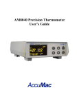
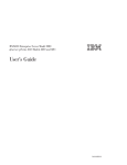
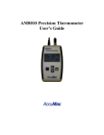
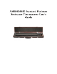
AM8040 Precision Thermometer User’s Guide AM8040 Precision Thermometer User’s Guide Table of Contents Important Notice ---- Warning .......................................................... 3 1. Introduction .................................................................................. 4 1.1. Main Application ....................................................................... 4 1.2. Main Features ............................................................................ 4 2. Main Specification........................................................................ 6 2.1. Main Specifications ................................................................... 6 2.2. Sensor Types.............................................................................. 6 3. User Interface ............................................................................... 7 4. General Operations ....................................................................... 8 4.1. Connecting the probe/sensor ..................................................... 8 4.2. Instrument connection with AC power ..................................... 8 4.3. Instrument front panel display and touchpad ............................ 9 5. Instrument Calibration and Accuracy Adjustments ................... 11 5.1. 100 Ω calibration ..................................................................... 12 5.2. 25 Ω calibration ....................................................................... 14 6. Selection of Sensors and Adjustment of Parameters ................. 18 7. Wireless Data Acquisition .......................................................... 24 8. Using a Flash Drive(U disk)for Data Acquisition ................ 30 9. Using the USB Interface for Data Acquisition .......................... 34 10. Appendix: Installation of USB Driver .................................... 37 11. Limited Warranty & Limitation of Liability ........................... 41 Page 1 AM8040 Precision Thermometer User’s Guide Please read the “Important Notice” information in the next page before turning on the power of this instrument! Page 2 AM8040 Precision Thermometer User’s Guide Important Notice ---- Warning Check the position of “Measurement/Calibration Switch” on the rear panel. Please refer to Figure 2. The switch must be at measurement (left) position. Loss of calibration data will occur if the switch is at the calibration (CAL) position when the instrument is used in measurement application. The instrument is calibrated before shipment. Only qualified calibration professionals with proper standard resistors should perform the calibrations of this device. Please refer to 5. Instrument Calibration And Accuracy Adjustments Page 3 AM8040 Precision Thermometer User’s Guide 1. Introduction AM8040 precision thermometer is a desktop temperature measurement and calibration device. It can work together with various types of platinum resistance thermometer (PRT) sensors. The measured temperature is calculated by the embedded microcontroller following ITS-90 standard or CVD conversion method. This precision thermometer has strong data acquisition capability. Users can acquire and record data using an USB cable connecting to a PC, or using a Flash drive by simply ‘plug-and-record’. Alternatively, it can work with an optional wireless module to acquire and record data remotely through wireless. With these flexible peripherals, temperature data can be captured and saved in real time easily for various applications. 1.1. Main Application Temperature calibrations or precision temperature measurements. Work with Standard Platinum Resistance Thermometers (SPRTs), secondary platinum resistance thermometers (Secondary PRTs) and precision industrial platinum resistance thermometers (IPRTs). Wireless/wire/flash real time temperature measurement and acquisition. 1.2. Main Features High accuracy, 0.008ºC at 0ºC. High resolution,0.001ºC Concurrent platinum sensor temperature measurement and data capturing. Concurrent display of sensor’s temperature in Celsius ºC, ºF, resistance Ω. 2.7” large size OLED display. Page 4 AM8040 Precision Thermometer User’s Guide Touchpad for function control. Flexible sensor parameter adjustment and setting. USB interface to computer for real time temperature capturing and data saving. Wireless real time temperature data capturing with optional external wireless module. Real time temperature data capturing and saving to flash drive. Page 5 AM8040 Precision Thermometer User’s Guide 2. Main Specification 2.1. Main Specifications Range of temperature measurement:-200ºC ~ 850 ºC Instrument resolution:0.001 ºC Instrument accuracy: 25Ω standard platinum 100Ω standard or industrial temperature sensor platinum temperature sensor ±0.015 ºC @ -196 ºC ±0.010 ºC @ -200 ºC ±0.010 ºC @ 0 ºC ±0.008 ºC @ 0 ºC ±0.015 ºC @ 232 ºC ±0.009 ºC @ 232 ºC ±0.020 ºC @ 420 ºC ±0.01 ºC @ 420 ºC ±0.025 ºC @ 660 ºC ±0.015 ºC @ 660 ºC ±0.025 ºC @ 850 ºC Instrument short term stability: o ±0.001 ºC(with 100Ω platinum sensor) o ±0.003 ºC(with 25Ω platinum sensor) Instrument working environment:15ºC ~ 35 ºC Power supply:AC 100V ~ 240V Power consumption:< 15 W Dimension :180 mm x 65 mm x 200 mm Weight :300g 2.2. Sensor Types SPRT or PRT with temperature coefficient α=0.003925 (WGa≥1.11807). IPRT with temperature coefficient α=0.00385. Page 6 AM8040 Precision Thermometer User’s Guide 3. User Interface Front Panel: Flash Drive Wireless Status Status USB status Sensor Type Main Menu Flash Drive Key Recording Start/Stop Key Main Display Left Key Parameter Return Key Adjust /Right Key Key Figure 1: Front Panel Rear Panel: AC Power Inlet & Switch Flash Drive Interface Sensor terminals USB Interface Measurement /Calibration Switch Figure 2: Rear Panel Page 7 Warning:Unless calibration is needed do NOT put the switch on ‘Cal’. AM8040 Precision Thermometer User’s Guide 4. General Operations AM8040 is a high accuracy digital thermometer working with a fourwire platinum resistance thermometer (PRT) sensor. The details of AM8040 operations are shown as follows: 4.1. Connecting the probe/sensor Four-wire sensor should be connected to the “Sensor” terminals at the rear panel. Figure 3 shows how the four wire sensor should be connected. It should be noted that the “Measurement/Calibration” switch should be at “Measurement” position. pair Measurement/Calibration Switch Figure 3: Rear Panel and Sensor Terminals 4.2. Instrument connection with AC power AM8040 must work with power of AC100V~240V. Page 8 pair AM8040 Precision Thermometer User’s Guide 4.3. Instrument front panel display and touchpad After power is on and a sensor is connected, AM8040 shows some initialization information, and then display information including the instrument’s interface status, measured temperature in Celsius degree, the sensor resistance and temperature in Fahrenheit degree. These are shown in 4 lines as following figure. There is a status sign which blinks at the upper left corner of the LCD display functioning as a status indicator. The status sign blinks when the device is powered on. Line1 is the instrument’s interface status, including USB flash drive, wireless communication status and USB to computer interface status. If “Udr”is displayed, it means that a flash flash drive is connected to the Host USB interface; if “ZB-xx ” is displayed, where “xx” are numbers, it means Zigbee wireless data capturing is working; if the display shows“USB”on the top line, it informs the user that AM8040 is connected to a computer’s USB interface. The “t=” at Line2 shows the measured temperature of the sensor. The“IPRT” at the end of the Line2 tells the type of sensor of sensor. AM8040 supports two types of sensors. “SPRT” indicates a 25Ω or 100 Ω standard platinum resistance thermometers with α=0.003925. “IPRT” indicates a 100Ω industrial platinum Page 9 AM8040 Precision Thermometer User’s Guide resistance thermometer with α=0.00385. The “C” is displayed at end of Line2, it means the temperature is measured is in Celsius degree. Line3 shows the sensor resistance. Line 4 shows the temperature in Fahrenheit degree. AM8040 has three display pages of the measured data and these pages can be scrolled to show different information. The above sample is page1. The third page shows the resistance of the sensor. The second page is the combination of page1 and page3. User can scroll up and down these three pages by pressing or key. MENU The menu key and return/right shift key can be used for sensor selections and parameter adjustments. The flash drive REC recording start/stop key can be used for data saving to flash drive. The details are in 5 Instrument Calibration and Accuracy Adjustment, and 6 Selection of Sensors and Adjustment of Parameters. Page 10 AM8040 Precision Thermometer User’s Guide 5. Instrument Calibration and Accuracy Adjustments AM8040 is designed for accurate temperature measurements by measuring the sensor resistance and converting it to temperature. Consequently, the resistance measurement is very critical and the instrument must be calibrated correctly. Every AM8040 is calibrated before shipment. Users can calibrate AM8040 using standard resistors with calibrated values. One year calibration interval is recommended. Warning: It is required to set correct R0 or Rtpw value of the sensor before calibrations. To calibrate AM8040 in the range from 10 Ω to 50 Ω, R0 or Rtpw needs to be set to 25 Ω. To calibrate AM8040 in the range from 50 Ω to 375 Ω, R0 or Rtpw needs to be set to 100 Ω. The calibration should be done in an environment with room temperature of 22±2°C. Page 11 AM8040 Precision Thermometer User’s Guide Instrument calibration procedure: (No special sequence for 100 Ω and 25 Ω calibrations) 5.1. 100 Ω calibration 5.1.1. Turn off the power, put the measurement/calibration switch to the “CAL”side (right side). Please see Figure 4 for details. Switch to “CAL” side before calibrations. Figure 4: Calibration Configuration at Rear Panel. 5.1.2. Turn on power, after initialization , AM8040 shows the calibration main menu. There are two calibrations selections: 100 Ohm CALIBRATION and 25 Ohm CALIBRATION. The following is an illustration of the 100 Ohm CALIBRATION. * CALIBRATION MENU * ------------------------------------------> 100 Ohm CALIBRATION 25 Ohm CALIBRATION Enter = Yes 5.1.3. Use or key on the key pad to select the calibration. A “>” sign is displayed in front of the selected line. For example, the above figure shows that 100 Ohm CALIBRATION is selected. Page 12 AM8040 Precision Thermometer User’s Guide Pressing the key will start the calibration program, and the following display will appear: * 100 Ohm CALIBRATION ------------------------------------------Connect a 100 Ohm Standard Resistor and Press Enter Menu= Exit Enter = Yes 5.1.4. The instrument will show “Connect a 100 Ohm Standard Resistor and Press Enter” to indicate that a 100Ω must be connected first. Users can exit the calibration by pressing main menu ( *CALIBRATION MENU*). MENU key to go back to 5.1.5. After the sensor is correctly connected, press key to start the calibration. The instrument will display “Waiting…” for a few seconds and should display some values as following: * 100 Ohm CALIBRATION 100R Rs = OHM 100.0238 Rt = 111.0000 Menu= Exit OHM <^v>=Adj 5.1.6. To calibration the instrument, users must adjust the value at the third line (100.0238 as shown above) to match the standard resistor’s resistance. For example, if the resistance of the standard resistor is 100.0038ohm, users can move the underline cursor to the position where the value will be adjusted by using and key, Page 13 AM8040 Precision Thermometer User’s Guide and users can adjust the value by using following picture shows the adjusted result. and key. The * 100 Ohm CALIBRATION 100R Rs = OHM 100.0038 Rt = 100.0038 Menu= Exit OHM <^v>=Adj 5.1.7. It is required to wait for 15 to 20 seconds before the data are stable. The next step is to save the calibrated data to the instrument. MENU To save the data, press the to inform the option to save. key, and the third line data will blink 5.1.8. To save this calibration value, press and hold the key and then press the key at the same time. This operation will store the calibration data to the instrument, and the program will go back to the main menu (*CALIBRATION MENU*). If users DO NOT want MENU to save the data, press the key and the display page will be back to main menu ( *CALIBRATION MENU*). 5.2. 25 Ω calibration 5.2.1. The process of 25 Ω calibrations is similar to that of 100 Ω Calibration. Frist, turning off the power of the instrument and ensure the measurement/calibration switch at the rear panel to the “CAL” side (right side), as shown in Figure 4. Page 14 AM8040 Precision Thermometer User’s Guide 5.2.2. Choose 25 Ohm CALIBRATION under main menu ( *CALIBRATION MENU*) by pressing or key to move the “>” cursor to the “25 Ohm CALIBRATION” line: * CALIBRATION MENU ------------------------------------------100 Ohm CALIBRATION > 25 Ohm CALIBRATION Enter = Yes 5.2.3. Press key to start the program CALIBRATION. The instrument will show: of 25 Ohm * 25 Ohm CALIBRATION ------------------------------------------Connect a 25 Ohm Standard Resistor and Press Enter Menu= Exit Enter = Yes 5.2.4. Follow the “Connect a 25 Ohm Standard Resistor and Press Enter” instruction to connect a 25Ω to sensor terminals. A standard resistor of 25Ω must have a value close the 25Ω; otherwise the calibration will not be accurate. 5.2.5. Press key to start the 25Ω calibration. the instrument should display “Waiting…” for a few seconds and then show: Page 15 AM8040 Precision Thermometer User’s Guide * 25 Ohm CALIBRATION 25R Rs = OHM 25.9977 Rt =25.0000 Menu= Exit OHM Enter = Yes The value on the third line is the parameter to be adjusted and this value must match the standard resistance of the 25Ω resistor. For example, the above figure shows the current value of 25.9977, but the standards resistor value is 24.9977. This value can be adjusted by using or key to move the “_” to the position where the value will be tuned, and using or key to adjust the value. After the adjustment, the instrument should display: * 25 Ohm CALIBRATION 25R Rs = OHM 24.9977 Rt =24.9977 Menu= Exit OHM Enter = Yes 5.2.6. It is required to wait for 15 to 20 seconds before reading is stable. The next step is to save the calibrated data to the instrument. MENU To start the data saving, press the key, and the third line data will blink to indicate the option to save. 5.2.7. To save this calibration results, press and hold the key and then pressing the key at the same time. This will save the calibration data to the instrument, and the program will go back to the main menu (*CALIBRATION MENU*). If users DO NOT want Page 16 AM8040 Precision Thermometer User’s Guide MENU to save the data, press the key and go back to main menu ( *CALIBRATION MENU*).。 Switch setting after calibration After the calibration, turn off the AC power ; Set the Measurement/Calibration switch at the rear panel to the left side (away from “CAL”) Page 17 AM8040 Precision Thermometer User’s Guide 6. Selection of Sensors and Adjustment of Parameters AM8040 can work with different types of PRT probes/sensors. It allows users to select probe types and input the parameters of the probes. The probes compatible with AM8040 are: 25 Ω or 100 Ω standard SPRTs, or 25 Ω or 100 Ω secondary reference PRTs, or 100 Ω IPRTs. The temperature coefficient of these sensors can either be 0.00385 Ω/Ω/°C or 0.003925 Ω/Ω/°C. The sensor types working with AM8040 are classified and named as IPRT and SPRT: If the probe is an industrial or precision platinum resistance thermometer probe with a temperature coefficient of 0.00385 Ω/Ω/°C, AM8040 will categorize the probe as “IPRT”. AM8040 calculates temperature according to CVD (IEC751) method. If the probe is a SPRT, or a secondary PRT with temperature coefficient of 0.003925 Ω/Ω/°C (WGa>=1.11807), AM8040 will categorize the probe as “SPRT”. AM8040 calculates temperature according to ITS-90 formula. Steps to select sensor type and input parameters: MENU 1. Under normal working state after power on, press key and then press key in 3 seconds, AM8040 will go to the parameter adjustment main menu, and the display will show: Page 18 AM8040 Precision Thermometer User’s Guide There are three options at this step: i. Sensor Setting. This is for sensor parameter adjustments. Users can select sensor type and do parameter adjustment. ii. U-Drive Setting. Users can select data saving rate to external flash drive. iii. Wireless Setting. Users can select wireless communication settings (optional). 2. Press or key to move the high lighten line with “>” to “Sensor Setting”. Press key to enter Sensor setting adjustment program as shown below. The sensor type can be “IPRT” or “SPRT”. Users can select either one by moving the “>” to the sensor type, and then press key. Users can exit this selection MENU screen by pressing key. The figure below shows that SPRT sensor type is selected. 3. Press key is to go to parameter adjustment menu: Page 19 AM8040 Precision Thermometer User’s Guide 4. If the type of sensor is SPRT, the adjustable parameters are Rtp, a, b, c, a4 and b4. The details of these parameter definitions can be found from ITS-90. As an example, calibration agencies provide following parameters after SPRT is calibrated: Rtp: probe’s resistance at triple point of water. a4 and b4:low temperature range parameters. a, b and c:high temperature range parameters (c can be “0” for some instances. Please refer to ITS-90 for more information.) 5. If the sensor type is IPRT, the adjustable parameters are R0, A, B and C. The details of the parameter definitions can be found from the industrial platinum resistance thermometer calibration procedure. As an example, calibration agencies provide following parameters after IPRT is calibrated: Page 20 AM8040 Precision Thermometer User’s Guide R0:the sensor’s resistance at 0°C. A and B: the temperature coefficients when temperature is higher than 0°C. C: the temperature coefficient when the temperature is lower than 0°C. 6. , , , and key can be used together to adjust these parameters. The parameters can also be saved into the instrument. The following example is the procedure of adjusting and saving Rtp and a4 of a SPRT. The other parameter adjustments follow the same process. MENU a. To adjust Rtp,continue the operation of 4, press or key to move the cursor to “>SET Rtp”, and then press key to go to Rtp adjustment program. [SPRT SETTING] Rtp = OHM MENU=Exit <^v> = Adj b. The instrument will display the current Rtp value. The digit with bottom blinking bar indicates the adjustable position. Users can use and key to move this position and use and key to adjust the value. MENU c. After Rtp is adjusted, press key. The display will remind users to save or not to save the adjusted value by flashing the adjusted Rtp. Press key to save the value or Page 21 AM8040 Precision Thermometer User’s Guide MENU press key to exit the program without saving and go back to the parameter adjustment menu. d. The following is the a4 adjustment procedure. Continue from 4, press and key to move the cursor to “>SET a4”, and then press as shown below: key to go to a4 adjustment program, The second line displays the current a4 value, and the next two lines show the adjustment selections. a4 adjustment is different from Rtp adjustment as the value of a4 can be “0”. If a4 is “0”, users can move the cursor by using and key to “SET A4=0” line and press the key to confirm the selection; if a4 is a value other than “0”, user can move the cursor to “ADJUST a4” line and then press a4 adjustment program. Page 22 key to go to AM8040 Precision Thermometer User’s Guide e. The current a4 value will be displayed. To adjust this value, press or key to move the underline cursor to the position where the value will be adjusted and then adjust it by moving or key. f. After adjustment, users can choose to save or quit the a4 MENU adjustment by pressing the key. The a4 line will be flashing to remind the user that a change has been made. To save the changes, press key; if not, press the program will go back to previous screen. MENU key and g. Other parameter adjustments are similar to the above Rtp and a4 adjustment. h. After all the adjustments are made, users can go back to the MENU main menu by pressing key multiple times until AM8040 go back to the main screen of measurement. Page 23 AM8040 Precision Thermometer User’s Guide 7. Wireless Data Acquisition Some AM8040 precision thermometers (Model# AM8040-W) are equipped with wireless module to transmit data wirelessly. Free software for this feature is included with the AM8040-W. Following components are need for this feature: AM8040 precision thermometer with embedded wireless function. A wireless transceiver. A USB cable. Computer with USB interface and Windows XP (or above) operating system. Wireless Transceiver USB cable AM8040-W PC with USB interface running Wireless Reader Figure 5: AM8040-W Wireless Data Acquisition. Directions for setting up the wireless communication system: Page 24 AM8040 Precision Thermometer User’s Guide 1) The AM8040 precision thermometer must be on and connected to a probe. 2) The computer and wireless transceiver must be within 50m (indoor) or 80m (outdoor) distance from AM8040. The computer must be powered on. 3) Connect the wireless transceiver to the computer with a USB cable. Place it at a high spot for best performance. The system setup is shown in Figure 5 4) After connecting the wireless transceiver to the computer, the user will be required to install the USB drivers. The detailed instructions for this are shown in the Appendix. 5) After the installation of USB drivers, the user will need to install the free software on the CD included with the AM8040. Insert the CD into the computer’s CDROM drive and copy the file named “CoolDragon_Air_Reader.exe” to the computer. 6) Once the file has finished copying, double click on the icon “CoolDragon_Air_Reader” to begin installation. The following screen will display: Page 25 AM8040 Precision Thermometer User’s Guide 7) “The Base Status” and “Remote” should display “Wireless Base RF OK” and “Wireless Remote OK” to confirm the wireless connection. The value after “ADDR” shows the wireless address of AM8040 precision thermometer. The data after “RSSI” is the wireless signal strength which should be a two-digit number after clicking on “Start”. The RSSI should be greater than -99dBm. Otherwise, the wireless signal is too weak and the link is not stable. To increase the wireless power, users can move the instrument closer to computer or increase the height of the Wireless Transceiver. If it is still too weak, the environment is not suitable for wireless communication. 8) To begin wireless data acquisition, clicking on “Start”. If the wireless signal is good enough, AM8040 should display “ZB-xx” where “xx” means the wireless signal strength. At the same time, CoolDragon_Air_Reader should also show the signal strength. The following figure is an example. Page 26 AM8040 Precision Thermometer User’s Guide 9) The wireless data acquisition can be halted by clicking on “Stop”, or clicking on “Exit” to quit the program. The default setting for sampling period is 1 second. The data acquisition can be restarted by clicking on “Start” if “Stop” is pressed before. 10) CoolDragon_Air_Reader can also save the captured data to a file “Air_data.txt”. The data sampling rate can be adjusted. The minimum sampling period is 1 second. Other data sampling period can be set by following the instruction. As shown in the above figure, below “Data Saving” there is “Every x Sec” where x means the sampling period with unit of second. It is noted that this sampling period can be adjusted only when the sampling is stopped or halted. For example, if the sampling period in the above figure is required to change, the program must be halted by clicking on “Stop” button first, and then users can change the sampling period. The sampling period must be integer. The data sampling can be restarted after the modification. Page 27 AM8040 Precision Thermometer User’s Guide If the captured data need to be saved, users can start the saving by clicking on “Start” , and then clicking on “REC” button. The captured temperature can be saved into “Air_data.txt”, and “Recording…” can be seen;if users want to stop data saving, clicking on “END” or “Stop” , the temperature data capturing can be stopped. The following is an example with 4 second period. 11) The data format saved in the file of Air_data.txt can be shown as following data: Time t(C) 12:10:12 +130.735 12:10:13 +130.735 12:10:14 +130.735 12:10:15 +130.735 12:10:16 +130.735 Page 28 AM8040 Precision Thermometer User’s Guide 12:10:17 +130.735 end recording Time t(C) 12:10:28 +130.735 12:10:32 +130.735 12:10:36 +130.734 end recording The first column is the sampling time which should be same as the computer time. The second column lists the temperature, each time “Stop” is pressed, the data saving will be halted, and “end recording” will be added to the file. If users want to continue data saving, users can clicking on “REC”, the new data will be added to the last line of the previous data. The above example illustrated that the data are stored two times: the first time is 1 second, the second time the sampling period is 4 seconds. Page 29 AM8040 Precision Thermometer User’s Guide 8. Using a Flash Drive(U disk)for Data Acquisition The flash drive recording start/stop key to the USB flash drive. REC can be used for saving data There is a USB port on the rear panel of the AM8040 which can be used to store the measured temperature data to a flash drive. Any flash drive with size lower than 4 gigabytes can be connected to the “UDrive” connector at the rear panel. The following steps explain how to transfer data from the AM8040 to a flash drive: 1) Connect a flash drive to the “UDrive” USB interface at the rear panel of AM8040. 2) After the flash drive is connected when AM8040 is powered on the display screen will show some quick information “Device Detected” “D:/p” to indicate that the flash drive is detected, and the upper left corner of the display should display “UDr” to remind users that a flash drive is connected and can be used for data capturing. 3) If the flash drive is connected before the power is on, AM8040 will show the quick information “Device Detected P2” during initialization to indicate that the flash drive is detected, and the left up corner of the display should display “UDr” to remind users that a flash drive is connected and can be used for data capturing. 4) If users want to save the temperature data measured by AM8040 to the flash drive, just press the R EC key on the front panel,the AM8040 will produce a short beep sound and the LED above the R EC will be turned on. This is to inform that the temperature data is being written to the flash drive. The file name that data is saving Page 30 AM8040 Precision Thermometer User’s Guide to is with the name of MYDATA.txt with sampling period 0.97 second. 5) If users want to stop the data saving, just press R EC key on the front panel,AM8040 will produce a short beep sound and the LED above R EC key will be off to show the end of data saving. 6) The following list is an example of data saved in MYDATA.txt file of the flash drive. The fist column is temperature in Celsius t(C); the second column is time with unit of second. An “end” is written to the file to show that R EC key is pressed. i. t(C) Time ii. +267.178 0.24 iii. +267.178 1.21 iv. +267.178 2.17 v. +267.178 3.14 vi. +267.178 4.10 vii. end 7) The above operations can be repeated to do multiple time data saving. 8) The temperature data file MYDATA.txt in the flash drive can be transferred to a computer. Just unplug the flash drive when it is in stopped status (the LED above the R EC key is off)and plug the flash drive to a computer USB connector. After the flash drive is detected by the computer OS, users can do the file copy as normal. The data saving period to flash drive can be adjusted by using the front panel. The default saving period is around 0.97 second,and it can be set as multiple times of this value with range of 1~65535. The detailed instruction is shown as below: Page 31 AM8040 Precision Thermometer User’s Guide MENU A. When AM8040 is in a normal working state, press key and then press key in 3 seconds, AM8040 will enter the main menu as below. B. Press key or key to move the cursor line with ”>” sign to “ > U-Drive Setting”, then press key to go to “Record Cycle adjustment” program as shown below. “N” represents the how often the temperature will be saved in multiple times of 0.97 second. The current value is “1”. C. If sampling frequency other than “1” is needed, the “Record Cycle” value can be adjusted as follows: press and hold key and then press key, a similar display as below will come out. It should be noted that this operation is a two key operation. Don’t release the key before pressing key. Page 32 AM8040 Precision Thermometer User’s Guide D. Press key or key to adjust the “N” value which must be equal or greater than 1 MENU E. After the adjustment, press key, the new adjusted value will blink to indicate whether the user wishes to save this new N value. For example,the following picture shows the new N value is 9, which means AM8040 will save a data to file every 9x0.97 seconds. To save this value, do the following two-key operation: press and hold key and then press key;if users DON’T want to save, just press MENU key to exit. Note: this operation is a two-key operation : do not release key before pressing key. otherwise the new value can not be saved. MENU F. After the adjustment, press multiple times until AM8040 goes back to main screen of measurement. Note: The parameter adjustments should only be performed while the flash drive is not in the data saving process. Page 33 AM8040 Precision Thermometer User’s Guide 9. Using the USB Interface for Data Acquisition AM8040 precision thermometer is designed with a USB interface for data acquisition and saving temperature data to a file. The following section describes the process of setting up a USB temperature data acquisition: 1) Connect a USB cable to the USB (USB B type) interface at the rear panel of AM8040 to a computer. USB Cable AM8040 Cool Dragon Digital Thermometer PC with USB interface Running CoolDragon USB Reader Figure6: AM8040 USB Temperature Data Acquisition System 2) The first time that an AM8040 is connected to a computer, the computer will require users to install the USB drivers. The detailed instruction is illustrated in the Error! Reference source not found.After the installation of these USB drivers, no further drivers will need to be installed. a. Copy “CoolDragon_USB_reader.exe” in the attached CD to the computer desktop. b. Double click on “CoolDragon_USB_reader” to start the software,the computer should show: Page 34 AM8040 Precision Thermometer User’s Guide c. The measurement can be started by clicking on “Start”, or can be stopped by clicking on “Stop”, or quit by clicking on “Exit”. The default sampling period is 1 second. The free software “CoolDragon_USB_reader” also function to save the captured temperature to “U_data.txt”. Users can also adjust the sampling requirements. The shortest sampling period is instruction is as follows. has data saving a file named period for their 1 second. The Find the “Every x Sec” section of the “Data Saving” section at the right side of the software’s GUI. The unit of the sampling period is second. If sampling period other than 1 second is required, users can adjust the value in the box. It is noted that the adjustment must be done when the measurement is “Stop” state as shown in the above figure, i.e., the adjustment must before “Start” or after “Stop” is pressed. If users want to save the captured temperature data, click on “Start” first, and temperature data should be received with a blinking tick Page 35 AM8040 Precision Thermometer User’s Guide showing the data capturing, then users can click on “REC” to start the data saving. The data will be saved to “U_data.txt” file,and “Recording…” should be shown ; if users want to stop the data saving, just click on “END” or “Stop” , and the temperature data saving will be stopped. The following figure shows that the data is saved to file with a sampling period of 3 seconds. The saved data format in “U_data.txt” is like: Time t(C) 22:43:07 +0.009 22:43:10 +0.008 22:43:13 +0.008 22:43:16 +0.008 22:43:19 +0.009 22:43:22 +0.008 end recording The first column is time which is identical to the computer time, and the second column shows the temperature. Page 36 AM8040 Precision Thermometer User’s Guide 10. Appendix: Installation of USB Driver Important Update: if your PC is running Windows7 (or higher version) operation system, you can skip USB driver installation process. Otherwise, please follow the instructions below. AM8040 precision thermometer and wireless transceiver are designed with USB interface. The installation of USB driver is required the first time these instruments are connected to a computer. The USB drivers for AM8040 precision thermometer and wireless transceiver are the same. The installation can be done by following the steps below: 1) When AM8040 precision thermometer and wireless transceiver are first connected to a computer,OS will pop up an auto detection information “Found New Hardware” . Page 37 AM8040 Precision Thermometer User’s Guide 2) Put the attached CD into the CDROM drive (assume the CDROM drive is E:),and then select “No, not this time” and click on “Next”, 3) Select “Install from a list or specific location (Advanced)” and then click “Next”, Page 38 AM8040 Precision Thermometer User’s Guide 4) Search E drive by using “Browse” as above figure,then click “Next”, 5) Select “Continue Anyway”, the computer will search for another file ”FTD2XX.sys”, 6) Use “Browse” to search for and select FTD2XX.sys,then click on “OK”. After the installation, the computer should show: Page 39 AM8040 Precision Thermometer User’s Guide 7) Select “Finish” to end the installation. 8) The computer should show “You new hardware is ready to use” to indicate the USB drivers are correctly installed. Page 40 AM8040 Precision Thermometer User’s Guide 11. Limited Warranty & Limitation of Liability The material contained in this document is provided “as is,” and is subject to being changed, without notice, in future editions. AccuMac shall not be liable for errors or for incidental or consequential damages in connection with the furnishing, use, or performance of this document or of any information contained herein. Should AccuMac and the user have a separate written agreement with warranty terms covering the material in this document that conflict with these terms, the warranty terms in the separate agreement shall control. Each product from AccuMac Corporation is warranted to be free from defects in material and workmanship under normal use and service. The warranty period is 1 year for Precision Thermometers. The warranty period begins on the date of the shipment. Parts, product repairs, and services are warranted for 90 days. The warranty extends only to the original buyer or end-user customer of an AccuMac authorized reseller. The warranty will not extended to products that have been misused, altered, neglected, or damaged by accident or abnormal conditions of operation or handling. To obtain warranty service, contact AccuMac Corporation at: 3150 N Arizona Ave Ste 103 Chandler, AZ 85225 USA Tel: (480)634-0603 Email: [email protected] Page 41