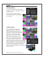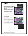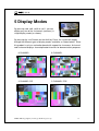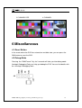
1
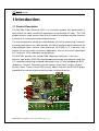
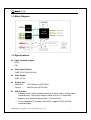
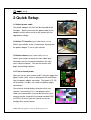
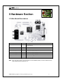
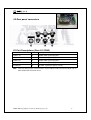
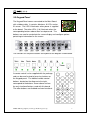
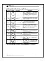
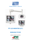
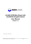
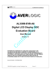
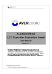
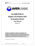
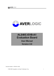
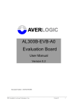
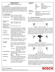
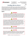
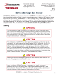
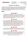
AL37204-EVB-A2
Evaluation Board
User Manual
Version 1.0
INFORMATION FURNISHED BY AVERLOGIC IS BELIEVED TO BE ACCURATE AND
RELIABLE. HOWEVER, NO RESPONSIBILITY IS ASSUMED BY AVERLOGIC FOR ITS USE,
OR FOR ANY INFRINGEMENTS OF PATENTS, OR OTHER RIGHTS OF THIRD PARTIES
THAT MAY RESULT FROM ITS USE. NO LICENSE IS GRANTED BY IMPLICATION OR
OTHERWISE UNDER ANY PATENT OR PATENT RIGHTS OF AVERLOGIC.
©2008-2009 Copyright by AverLogic Technologies, Corp.
AL37204-EVB-A1-User Manual-1.0-20090821
Version and Amendments
Date
03-23-2009
Version
1.0
Comments
Public Release
Author
Ken Liu
Disclaimer
THE CONTENTS OF THIS DOCUMENT ARE SUBJECT TO CHANGE WITHOUT NOTICE.
AVERLOGIC TECHNOLOGIES RESERVES THE RIGHT TO MAKE CHANGES WITHOUT
FURTHER NOTICE TO ANY PRODUCTS HEREIN TO IMPROVE RELIABILITY, FUNCTION
OR DESIGN. AVERLOGIC DOES NOT ASSUME ANY LIABILITY ARISING OUT OF THE
APPLICATION OR USE OF ANY PRODUCT OR CIRCUIT DESCRIBED HERIN; NEITHER
DOES IT CONVEY ANY LICENSE UNDER ITS PATENT RIGHTS, NOR THE RIGHTS OF
OTHERS.
CUSTOMERS ARE ADVISED TO CONSULT WITH AVERLOGIC OR ITS COMMERCIAL
DISTRIBUTORS BEFORE ORDERING.
©2008-2009 Copyright by AverLogic Technologies, Corp.
AL37204-EVB-A1-User Manual-1.0-20090821
Table of Contents
1
Introduction ...................................................................................................1
1.1 Product Description .......................................................................................................................... 1
1.2 Block Diagram................................................................................................................................. 2
1.3 Specifications ................................................................................................................................... 2
2 Quick Setup ......................................................................................................4
3 Hardware Section.............................................................................................5
3.1 Main Board Descriptions.................................................................................................................. 5
3.2 Rear panel connectors....................................................................................................................... 6
3.3 Keypad Panel.................................................................................................................................... 7
4 System Menu....................................................................................................9
4.1 Main Menu ....................................................................................................................................... 9
4.2 System Setup .................................................................................................................................... 9
4.3 Display Setup.................................................................................................................................. 10
4.4 Auto Sequence................................................................................................................................ 10
4.5 Camera Setup.................................................................................................................................. 11
4.6 Motion Setup .................................................................................................................................. 11
4.7 Event Setup..................................................................................................................................... 12
4.8 Event Report................................................................................................................................... 12
5 Display Modes................................................................................................13
6 Miscellaneous ................................................................................................14
6.1 Reset Button ................................................................................................................................... 14
6.2 Debug Mode ................................................................................................................................... 14
©2008-2009 Copyright by AverLogic Technologies, Corp.
AL37204-EVB-A1-User Manual-1.0-20090821
1 Introduction
1.1 Product Description
The AL37204 Video Processor EVB is an evaluation product that demonstrates a
total solution for video surveillance applications using Averlogic IC chips. This EVB
product receives video streams from up to 4 cameras to be processed and shown on
a monitor in a variety of convenient display formats.
The main components include one video decoder (AL244) for processing 4 channels
of analog video inputs, one video decoder (AL240) for analog to digital conversion for
video playback input, and one video processor (AL37204). It is a low-cost, easy
solution for real-time video surveillance applications that use 4-channel video output
to TV monitors, VCRs and digital storage devices.
The AL37204 provides four analog CVBS video input connectors. It has costeffective, high-quality NTSC/PAL video decoding technology with adaptive comb-filter
Y/C separation processing and quad video processing. It is also equipped with BCS
(Brightness, Contrast, Saturation and Hue) control, Scale Down Function, Re-play
function, Zoom, Freeze, Internal OSD overlay, Motion Detection and PIP/POP display
capabilities for monitoring and controlling video surveillance devices.
©2008-2009 Copyright by AverLogic Technologies, Corp.
1
1.2 Block Diagram
1.3 Specifications
Video standard support
NTSC
PAL
Video Input Formats
CVBS (CH1/CH2/CH3/CH4)
Video Output
CVBS (J2/J3)
Display size :
Horizontal:
Vertical
720/720 pixels (NTSC/PAL)
:
480/576 lines (NTSC/PAL)
EVB Function
Supports manual video standard selection to match various analog video
standard inputs. High quality adaptive comb-filter for Y/C separation.
Supports multi-window display modes (1/2/3/4/9/13/16).
Three embedded TV Encoders with DACS, supports NTSC and PAL
standard outputs.
©2008-2009 Copyright by AverLogic Technologies, Corp.
2
Supports manual adjustment of hue, brightness, contrast and saturation .
Supports individual channel freeze.
Supports PIP/POP function.
Supports motion detection / blind detection.
Internal OSD overlay with programmable bitmap type font for OSD display
.
Note: Please be aware that this is an Evaluation product only and not all functional
capabilities of Averlogic components are fully demonstrated by this product. Please
refer to the Averlogic website (www.averlogic.com) or contact your Averlogic
representative (see last page of this document) for more information.
©2008-2009 Copyright by AverLogic Technologies, Corp.
3
2 Quick Setup
2.1 Attach power cable
The power adapter unit itself will be attached to the
Plexiglas. Attach one end of the power cable to the
adapter and the other end to a wall socket with the
appropriate voltage.
2.2 Attach TV monitor (requires CVBS w/ RCA connector)
Attach your monitor to the J2 connector, located near
the power adapter. Turn on your monitor.
2.3 Attach camera (requires CVBS w/ RCA connector)
Attach your camera to one of the four video input
connectors on the rear panel located on the rightmost side of the panel. Turn on the camera and
begin transmitting a picture.
2.4 Turn on board power
After you turn on your camera and TV monitor, toggle the
power switch (sw2), which is located on the main board
near the power adapter connector. The green LED, D5,
will illuminate. If it does not, check the power supply
connections.
Your monitor should display the picture that your
camera is transmitting. If it is not displaying the
video, your connections may not be secure or your
camera may be setup with the wrong standard (PAL
or NTSC), for which you will need to review the
configuration section below.
©2008-2009 Copyright by AverLogic Technologies, Corp.
4
3 Hardware Section
3.1 Main Board Descriptions
Connector
Label
Description
Power Jack
CON1
12V DC power input port (current greater than 1A
recommended)
Power S/W
SW2
Power switch
Reset Button
SW3
Reset button
CVBS-Video Input
CON2
CVBS Video signal input port
CVBS-Video Output
J2
CVBS Video signal output port
CVBS-Video Output
J3
CVBS Video signal output port
Keypad Connecter
J6
Connector for Keypad Panel
IR Receiver
U10
Receives IR signal from Remote controller
Note: There are other jumpers and connectors on this EVB board that are not described and are
either disabled or not meant for use.
©2008-2009 Copyright by AverLogic Technologies, Corp.
5
3.2 Rear panel connectors
I/O Port Descriptions (Rear I/O CON2)
Connector
Label
Description
CVBS 1 IN
D
CVBS Video signal input port 1
CVBS 2 IN
C
CVBS Video signal input port 2
CVBS 3 IN
B
CVBS Video signal input port 3
CVBS 4 IN
A
CVBS Video signal input port 4
S-Video IN
G
S-Video signal input port (reserved)
Note: There are other jumpers and connectors on this EVB board that are not described and are
either disabled or not meant for use.
©2008-2009 Copyright by AverLogic Technologies, Corp.
6
3.3 Keypad Panel
The Keypad Panel comes connected to the Main Board
with a ribbon cable. It contains 8 buttons, 9 LEDs and an
IR sensor. The LED 9 illuminates when power is supplied
to the board. The other LEDs (1-8) illuminate when the
corresponding buttons above them are depressed. The
buttons are used to manipulate the screen display and configure options
pertaining to information on the screen.
The functions on the panel buttons correspond to the diagram shown below.
A remote control is also supplied with the package
and can be used instead of pressing buttons on
the Keypad panel. The labeled remote control
buttons, located on the diagram to the right,
correspond to the buttons shown above and are
the only functional buttons used with this board.
The other buttons are disabled and non-functional.
©2008-2009 Copyright by AverLogic Technologies, Corp.
7
Button and Remote Control Functions
Keypad Remote
Function
Description
SW4
Menu/Lock
This button displays the main configuration
“Menu” on the screen. It can also be
pressed to return to the previous screen.
This button can also be pressed for 3
seconds to either lock the menu or to
release it from lock mode.
SW5
Auto
Sequence
Display
This button is used to Automatically display
the different display modes, one after the
other, in sequence
Freeze/Debug
Freezes the video on all panels. Also can
be pressed for 3 seconds to enter I2C
debugging mode or to release from
debugging mode.
SW7
Mode/Enter
This button is used to switch between the
different display modes (1-panel, 2-panel
etc.). Also is used as the ”Enter” key when
using the Menu to configure display
options.
SW8
Right Arrow / CH4
Arrow to the right (during menu
configurations). Is also used to display CH4 in single panel display.
SW9
Left Arrow / CH-3
Arrow to the left (during menu
configurations). Is also used to display CH3 in single panel display.
SW10
Down Arrow / CH2
Arrow down (during menu configurations).
Also can be used to decrement a value
setting. Is also used to display CH-2 in
single panel display.
Up Arrow / CH-1
Arrow up (during menu configurations).
Also can be used to increment a value
setting. Is also used to display CH-1 in
single panel display.
SW6
SW11
See the “System Menu” section for a complete description of all functions.
©2008-2009 Copyright by AverLogic Technologies, Corp.
8
4 System Menu
MAIN MENU
1>
2>
3>
4>
5>
6>
7>
4.1 Main Menu
Pressing the “Menu” button (sw4) will
bring up the Main Menu in the center of
SYSTEM SETUP
DISPLAY SETUP
AUTO SEQUENCE
CAMERA SETUP
MOTION SETUP
EVENT SETUP
EVENT LIST
the screen, where you can select from 7
items. Use the up/down arrow keys (sw10,
sw11) to reach your selection. Use the
“enter” key (sw7) to execute the function.
You can use the sw4 button to also return
to the previous screen.
4.2 System Setup
The System Setup screen allows you to
configure the date, time, and video
standard (PAL, NTSC).
You can also lock the buttons on the panel.
The only way to unlock the panel is to
power down the system or use your
remote control, as it is not affected by the
lock.
You can also reset to the factory settings.
Since this is an evaluation board, simply
SYSTEM SETUP
powering down the system will also reset the settings
1>
back to the defaults.
2>
Use your up/down, left/right arrow keys to navigate the
screen and the “enter” key (sw7) to accept the
3>
4>
5>
DATE : YYYY-MM-DD
2009-01-08
TIME : HH-MM-SS
12:13:35
SYSTEM FORMAT:PAL
KEY LOCK:OFF
FACTORY RESET
configuration.
©2008-2009 Copyright by AverLogic Technologies, Corp.
9
4.3 Display Setup
In the Display Setup you have options to display the
Date and Time on the screen. You can also display a
“Title” on the screen which represents one of the four
cameras. The title will be in the format “CHXX” (e.g.
DISPLAY SETUP
1> DISPLAY ON SCREEN
*TITLE *DATE *TIME
2> BORDER LINE COLOR
BLACK GRAY RED
*WHITE BLUE GREEN
NO
CH01).
An asterisk next to the item indicates
that it is selected to be displayed.
The border line color that separates the
different camera panels on the screen
can also be changed. An asterisk next
to the color indicates the current
selection.
4.4 Auto Sequence
When auto sequencing is in effect (sw5),
the system will display the different screen
modes (1 panel, 2 panel, 3 panel etc.) one
after the other in succession. This setup
screen allows you to configure the amount
of time (in seconds) that any particular
display mode screen will pause on the
screen once displayed.
AUTO SEQUENCE SET
Unit:sec
---------------------------------CAMERA1:1 CAMERA2:1
CAMERA1:1 CAMERA2:1
MULTI-2:1
MULTI-3:1
MULTI-4:1
MULTI-6:1
MULTI-9:1
PIP-2:1
©2008-2009 Copyright by AverLogic Technologies, Corp.
10
4.5 Camera Setup
This screen allows you to set values for the
“Brightness”, “Contrast”, “Saturation” and “Hue”
for each camera.
You can also set the “Mirror” function
CAMERA SETUP
CAMERA
1
2
3
4
------------------------------------------BRIGHT
20 20 20 20
CONTRAST
80 80 80 80
SATURAST
40 40 40 40
HUE
80 80 80 80
MIRROR
OFF OFF OFF OFF
which horizontally flips the display picture
for any camera.
4.6 Motion Setup
You can configure motion detection
options on this screen. You can first
enable and disable motion detection for
each camera. You can also setup motion
detection sensitivity for each camera;
these values are in hexadecimal with
“000” representing the most sensitive.
After you have enabled Motion Detection
for a camera, you can run your hand
across the camera lens and you will see the motion
detection displayed on the screen, represented by
small black squares. As you adjust the “sensitivity”
MOTION SETUP
CAMERA
1
2
3
4
-------------------------------------------------ENABLE
OFF ON OFF OFF
SENSOR
00A 00A 00A 00A
of a camera’s motion detection, the number of
squares will increase or decrease inversely with the
sensitivity setting.
©2008-2009 Copyright by AverLogic Technologies, Corp.
11
4.7 Event Setup
Alert situations such as Motion Detection (Motion)
and Loss of Picture (Lose) can be detected for
each Channel (camera). You can turn
detection functionality on and off for
each channel.
EVENT SETUP
CHANNEL 1
2
3
4
------------------------------------------ALARM
OFF ON --- --MOTION OFF ON OFF OFF
LOSE
OFF ON OFF OFF
You can also set the Alarm function for
each camera which, for this EVB system,
records an entry for each alert in an
Alert file that you view in the Event
Report screen (see below)..
4.8 Event Report
The Event Report function displays all of
the alerts (Motion Detection and Loss of
Picture) that have been recorded in the
Alert file. Note that with this evaluation
board, you can only record up to 6 alerts.
You can delete all of the alerts in the file
by moving to the “DEL ALL” option at
the bottom-right corner of this screen
and pressing “enter” (sw7).
EVENT REPORT
NO YY-MM-DD HH:MM:SS CH
------------------------------------------1.
2.
3.
4.
5.
6.
------------------------------------------
©2008-2009 Copyright by AverLogic Technologies, Corp.
12
5 Display Modes
By pressing sw8, sw9, sw10 or sw11, you can
display any one of the 4 channels (cameras) in
single display mode (as shown).
By pressing the “sw4” button on the Auxiliary Panel, the system will toggle
through the different types of display modes available, as shown below. Since
this product is only an evaluation board with support for 4 cameras, 6-channel
and 9-channel displays show duplicated channels for demonstration purposes.
6 CHANNEL
9 CHANNEL
3 CHANNEL PIP
2 CHANNEL POP
©2008-2009 Copyright by AverLogic Technologies, Corp.
13
3 CHANNEL POP
4 CHANNEL
6 Miscellaneous
6.1 Reset Button
In the event where the EVB has entered an unstable state, you can press the
SW3 button to reset the EVB.
6.2 Debug Mode
Pressing the “SW6/Freeze” Key for 3 seconds will take you into debug mode.
Averlogic Debugging Tools can help you debug the EVB. You can find details with
the Averlogic Debugging Tools.
©2008-2009 Copyright by AverLogic Technologies, Corp.
14
CONTACT INFORMATION
AverLogic Technologies, Corp.
URL: http://www.averlogic.com
©2008-2009 Copyright by AverLogic Technologies, Corp.
15