1
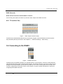
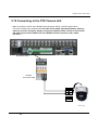
Digital Video Recorder
GND (Ground)
NOTE: All the connectors marked GND are common.
Connect the ground side of the Alarm input and/or alarm output to the GND connector.
AO 1 TO 4 (Alarm Out)
Figure — Alarm Output connector strips.
The DVR can activate external devices such as buzzers or lights. Connect the device to the AO (Alarm
Out) and GND (Ground) connectors. See Chapter 6 — Advanced Settings – Alarm Setup.
3.6 Connecting to the RS485
Figure — RS485 Connector.
The DVR can be controlled remotely by an external device or control system, such as a control keyboard
using RS485 half-duplex serial communications signals. The RS485 connector can also be used to control
PTZ (pan, tilt, zoom) cameras. Connect RX-/TX- and RX+/ TX+ of the control system to the TX-/RX- and
TX+/RX+ (respectively) of the DVR. See the PTZ camera or remote controller manufacture’s manual for
configuring the RS485 connection.
21