1
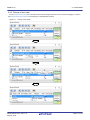
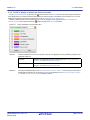
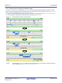
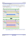
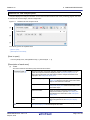
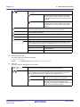
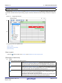
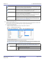
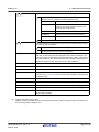
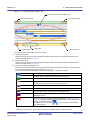
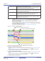
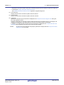
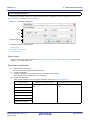
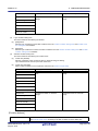
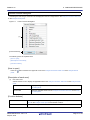
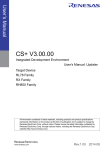
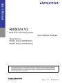
User’s Manual
RI850V4 V2
Real-Time Operating System
User's Manual: Analysis
Target Device
RH850 Family (RH850G3K)
RH850 Family (RH850G3M)
All information contained in these materials, including products and product specifications,
represents information on the product at the time of publication and is subject to change by
Renesas Electronics Corp. without notice. Please review the latest information published by
Renesas Electronics Corp. through various means, including the Renesas Electronics Corp.
website (http://www.renesas.com).
www.renesas.com
Rev.1.01
Sep 2015
Notice
1.
Descriptions of circuits, software and other related information in this document are provided only to illustrate the operation of
semiconductor products and application examples. You are fully responsible for the incorporation of these circuits, software,
and information in the design of your equipment. Renesas Electronics assumes no responsibility for any losses incurred by you
or third parties arising from the use of these circuits, software, or information.
2.
Renesas Electronics has used reasonable care in preparing the information included in this document, but Renesas Electronics
does not warrant that such information is error free. Renesas Electronics assumes no liability whatsoever for any damages
incurred by you resulting from errors in or omissions from the information included herein.
3.
Renesas Electronics does not assume any liability for infringement of patents, copyrights, or other intellectual property rights of
third parties by or arising from the use of Renesas Electronics products or technical information described in this document. No
license, express, implied or otherwise, is granted hereby under any patents, copyrights or other intellectual property rights of
Renesas Electronics or others.
4.
You should not alter, modify, copy, or otherwise misappropriate any Renesas Electronics product, whether in whole or in part.
Renesas Electronics assumes no responsibility for any losses incurred by you or third parties arising from such alteration,
modification, copy or otherwise misappropriation of Renesas Electronics product.
5.
Renesas Electronics products are classified according to the following two quality grades: “Standard” and “High Quality”. The
recommended applications for each Renesas Electronics product depends on the product’s quality grade, as indicated below.
“Standard”:
Computers; office equipment; communications equipment; test and measurement equipment; audio and visual
equipment; home electronic appliances; machine tools; personal electronic equipment; and industrial robots etc.
“High Quality”: Transportation equipment (automobiles, trains, ships, etc.); traffic control systems; anti-disaster systems; anticrime systems; and safety equipment etc.
Renesas Electronics products are neither intended nor authorized for use in products or systems that may pose a direct threat to
human life or bodily injury (artificial life support devices or systems, surgical implantations etc.), or may cause serious property
damages (nuclear reactor control systems, military equipment etc.). You must check the quality grade of each Renesas
Electronics product before using it in a particular application. You may not use any Renesas Electronics product for any
application for which it is not intended. Renesas Electronics shall not be in any way liable for any damages or losses incurred
by you or third parties arising from the use of any Renesas Electronics product for which the product is not intended by Renesas
Electronics.
6.
You should use the Renesas Electronics products described in this document within the range specified by Renesas Electronics,
especially with respect to the maximum rating, operating supply voltage range, movement power voltage range, heat radiation
characteristics, installation and other product characteristics. Renesas Electronics shall have no liability for malfunctions or
damages arising out of the use of Renesas Electronics products beyond such specified ranges.
7.
Although Renesas Electronics endeavors to improve the quality and reliability of its products, semiconductor products have
specific characteristics such as the occurrence of failure at a certain rate and malfunctions under certain use conditions. Further,
Renesas Electronics products are not subject to radiation resistance design. Please be sure to implement safety measures to
guard them against the possibility of physical injury, and injury or damage caused by fire in the event of the failure of a Renesas
Electronics product, such as safety design for hardware and software including but not limited to redundancy, fire control and
malfunction prevention, appropriate treatment for aging degradation or any other appropriate measures. Because the evaluation
of microcomputer software alone is very difficult, please evaluate the safety of the final products or systems manufactured by
you.
8.
Please contact a Renesas Electronics sales office for details as to environmental matters such as the environmental compatibility
of each Renesas Electronics product. Please use Renesas Electronics products in compliance with all applicable laws and
regulations that regulate the inclusion or use of controlled substances, including without limitation, the EU RoHS Directive.
Renesas Electronics assumes no liability for damages or losses occurring as a result of your noncompliance with applicable laws
and regulations.
9.
Renesas Electronics products and technology may not be used for or incorporated into any products or systems whose
manufacture, use, or sale is prohibited under any applicable domestic or foreign laws or regulations. You should not use
Renesas Electronics products or technology described in this document for any purpose relating to military applications or use
by the military, including but not limited to the development of weapons of mass destruction. When exporting the Renesas
Electronics products or technology described in this document, you should comply with the applicable export control laws and
regulations and follow the procedures required by such laws and regulations.
10. It is the responsibility of the buyer or distributor of Renesas Electronics products, who distributes, disposes of, or otherwise
places the product with a third party, to notify such third party in advance of the contents and conditions set forth in this
document, Renesas Electronics assumes no responsibility for any losses incurred by you or third parties as a result of
unauthorized use of Renesas Electronics products.
11. This document may not be reproduced or duplicated in any form, in whole or in part, without prior written consent of Renesas
Electronics.
12. Please contact a Renesas Electronics sales office if you have any questions regarding the information contained in this document
or Renesas Electronics products, or if you have any other inquiries.
(Note 1) “Renesas Electronics” as used in this document means Renesas Electronics Corporation and also includes its majorityowned subsidiaries.
(Note 2) “Renesas Electronics product(s)” means any product developed or manufactured by or for Renesas Electronics.
(2012.4)
How to Use This Manual
Readers
This manual is intended for users who design and develop application systems using
RH850 family products.
Purpose
This manual is intended for users to understand the functions of task analyzer tool manufactured by Renesas Electronics, described the organization listed below.
Organization
This manual consists of the following major sections.
1. GENERAL
2. FUNCTIONS
A. WINDOW REFERENCE
How to Read This Manual
It is assumed that the readers of this manual have general knowledge in the fields of electrical engineering, logic circuits, microcontrollers, C language, and assemblers.
To understand the hardware functions of the RH850 family.
-> Refer to the User's Manual of each product.
Conventions
Data significance:
Note:
Caution:
Remark:
Numeric representation:
Higher digits on the left and lower digits on the right
Footnote for item marked with Note in the text
Information requiring particular attention
Supplementary information
Decimal ... XXXX
Hexadecimal ... 0xXXXX
Prefixes indicating power of 2 (address space and memory capacity):
K (kilo)
210 = 1024
M (mega)
220 = 10242
Related Documents
The related documents indicated in this publication may include preliminary versions.
However, preliminary versions are not marked as such.
Document Name
RI Series
RI850V4 V2
Document No.
Start
R20UT0751E
Message
R20UT0756E
Coding
R20UT2889E
Debug
R20UT2890E
Analysis
This manual
Caution The related documents listed above are subject to change without notice. Be
sure to use the latest edition of each document when designing.
All trademarks or registered trademarks in this document are the property of their respective owners.
TABLE OF CONTENTS
1.
GENERAL . . . . . . . . . . . . . . . . . . . . . . . . . . . . . . . . . . . . . . . . . . . . . . . . . . . . . . . . 5
1.1
Overview . . . . . . . . . . . . . . . . . . . . . . . . . . . . . . . . . . . . . . . . . . . . . . . . . . . . . . . . . . . . . . . . . . . . . . . . . . . . . . 5
1.2
Features. . . . . . . . . . . . . . . . . . . . . . . . . . . . . . . . . . . . . . . . . . . . . . . . . . . . . . . . . . . . . . . . . . . . . . . . . . . . . . . 5
2.
FUNCTIONS. . . . . . . . . . . . . . . . . . . . . . . . . . . . . . . . . . . . . . . . . . . . . . . . . . . . . . . 6
2.1
Overview . . . . . . . . . . . . . . . . . . . . . . . . . . . . . . . . . . . . . . . . . . . . . . . . . . . . . . . . . . . . . . . . . . . . . . . . . . . . . . 6
2.2
Open Realtime OS Task Analyzer Panel . . . . . . . . . . . . . . . . . . . . . . . . . . . . . . . . . . . . . . . . . . . . . . . . . . . . . . 7
2.3
Set Trace Start Event . . . . . . . . . . . . . . . . . . . . . . . . . . . . . . . . . . . . . . . . . . . . . . . . . . . . . . . . . . . . . . . . . . . . . 8
2.4
Open Analysis Result Panel . . . . . . . . . . . . . . . . . . . . . . . . . . . . . . . . . . . . . . . . . . . . . . . . . . . . . . . . . . . . . . . 8
2.4.1
On/Off of item display . . . . . . . . . . . . . . . . . . . . . . . . . . . . . . . . . . . . . . . . . . . . . . . . . . . . . . . . . . . . . . . . . 9
2.4.2
Filtering of analysis information . . . . . . . . . . . . . . . . . . . . . . . . . . . . . . . . . . . . . . . . . . . . . . . . . . . . . . . . 10
2.4.3
Change of sort order. . . . . . . . . . . . . . . . . . . . . . . . . . . . . . . . . . . . . . . . . . . . . . . . . . . . . . . . . . . . . . . . . 11
2.4.4
On/Off of display of state lines and event marks . . . . . . . . . . . . . . . . . . . . . . . . . . . . . . . . . . . . . . . . . . . 12
2.4.5
Limiting range of execution transition state . . . . . . . . . . . . . . . . . . . . . . . . . . . . . . . . . . . . . . . . . . . . . . . 13
2.4.6
Limiting range of usage status . . . . . . . . . . . . . . . . . . . . . . . . . . . . . . . . . . . . . . . . . . . . . . . . . . . . . . . . . 14
2.5
Clear Analysis Information . . . . . . . . . . . . . . . . . . . . . . . . . . . . . . . . . . . . . . . . . . . . . . . . . . . . . . . . . . . . . . . . 15
2.6
Save Analysis Information . . . . . . . . . . . . . . . . . . . . . . . . . . . . . . . . . . . . . . . . . . . . . . . . . . . . . . . . . . . . . . . . 16
2.7
Restore Analysis Information . . . . . . . . . . . . . . . . . . . . . . . . . . . . . . . . . . . . . . . . . . . . . . . . . . . . . . . . . . . . . . 17
A.
WINDOW REFERENCE. . . . . . . . . . . . . . . . . . . . . . . . . . . . . . . . . . . . . . . . . . . . . 18
A.1
Description . . . . . . . . . . . . . . . . . . . . . . . . . . . . . . . . . . . . . . . . . . . . . . . . . . . . . . . . . . . . . . . . . . . . . . . . . . . . 18
Realtime OS Task Analyzer panel . . . . . . . . . . . . . . . . . . . . . . . . . . . . . . . . . . . . . . . . . . . . . . . . . . . . . . . . . . . . . . . 19
Analysis Result panel . . . . . . . . . . . . . . . . . . . . . . . . . . . . . . . . . . . . . . . . . . . . . . . . . . . . . . . . . . . . . . . . . . . . . . . . . 21
Filter Settings dialog box . . . . . . . . . . . . . . . . . . . . . . . . . . . . . . . . . . . . . . . . . . . . . . . . . . . . . . . . . . . . . . . . . . . . . . 28
Column Chooser dialog box . . . . . . . . . . . . . . . . . . . . . . . . . . . . . . . . . . . . . . . . . . . . . . . . . . . . . . . . . . . . . . . . . . . . 31
Chart Visualization Chooser dialog box . . . . . . . . . . . . . . . . . . . . . . . . . . . . . . . . . . . . . . . . . . . . . . . . . . . . . . . . . . . 32
Save As dialog box . . . . . . . . . . . . . . . . . . . . . . . . . . . . . . . . . . . . . . . . . . . . . . . . . . . . . . . . . . . . . . . . . . . . . . . . . . . 33
Open dialog box . . . . . . . . . . . . . . . . . . . . . . . . . . . . . . . . . . . . . . . . . . . . . . . . . . . . . . . . . . . . . . . . . . . . . . . . . . . . . 35
RI850V4 V2
1. GENERAL
1. GENERAL
CS+ is an integrated development environment for the development of application systems for microcontrollers manufactured by Renesas Electronics. CS+ allows the user to perform a series of operations including design, coding, build,
and debugging.
Of such a series of development processes, this manual describes a task analyzer tool which is an effective tool for analyzing processing programs (tasks, interrupt handlers, etc.) using the features of real-time OS "RI850V4".
1.1 Overview
With the increasing sophistication and high functionality of microcontrollers, the processing programs have become
increasingly large and complex.
Given such a processing program, the conventional debugger, while adequate in performing the logical analysis of a
processing program, runs into difficulties when confronted with such time-related analysis requirements as processing
execution timing issues and overall system performance evaluation. As a result, performing such analyses using the conventional debugger has required enormous time.
In response to such a market condition, Renesas Electronics, while providing powerful microcontrollers including the
RH850 family, is offering a task analyzer tool with the objective of aiding the quantitative analysis of processing programming.
The task analyzer tool is intended for the analysis of the execution transition state of the processing program incorporating real-time OS "RI850V4" for the RH850 family, the state of real-time OS resource usage, the CPU usage status, and so
forth. Through linkage to CS+, the task analyzer tool provides the functions of capturing event occurrences (the issuing of
service calls, the generation of interrupts, etc.) as trace data and graphically displaying the information.
Consequently, by using the task analyzer tool, the user can easily analyze the state of processing program execution,
the state of real-time OS resource usage, the CPU usage status, and so forth.
1.2 Features
The task analyzer tool provides the following features:
- Displays the processed program
Through the graphical display of the execution transition state of a processing program incorporating RI850V4, the
task analyzer tool can explicitly analyze the execution transition state of the processing program involving task switching based on service call issuance, control transfer to the interrupt handler occasioned by the generation of an interrupt, and so forth.
- Displays the Real-time OS resource usage status
When a service call is issued by the processing program, the task analyzer tool can display the status of access to
real-time OS resources (including semaphores and event flags) as an event mark. In this manner, the task analyzer
tool permits the explicit analysis of the usage status of various real-time OS resources.
- Displays the CPU usage status
By displaying the CPU usage status of the processing program (CPU usage rate, total execution time, etc.) in table
form, the task analyzer tool permits the quantitative analysis of processing program execution time.
- Linkage to CS+
The capability to jump from the task analyzer tool to the Editor panel, the Disassemble panel, etc. of CS+ permits the
speedy identification.
R20UT2891EJ0101 Rev.1.01
Sep 30, 2015
Page 5 of 40
RI850V4 V2
2. FUNCTIONS
2. FUNCTIONS
This chapter describes the principal functions provided by the task analyzer tool, along with operating procedure.
2.1 Overview
The task analyzer tool can be used to verify analysis information (the state of processing program execution, the state of
real-time OS resource usage, the CPU usage status, etc.) that dynamically changes according to the state of execution of
the processing program.
The task analyzer tool requires the following operating procedure:
(1)
Start CS+
From the Windows [Start] menu, launch CS+.
Remark
(2)
Read a project
Read the project to be analyzed.
Remark
(3)
(5)
(6)
Remark 1.
For details on the "[Task Analyzer] tab", see the "RI850V4 V2 Real-Time Operating System User's
Manual: Coding".
Remark 2.
When generating a load module, CS+ references the content of the [Selection of trace mode] settings and generates a load module that is optimal for the trace mode.
Download the load module
Download the load module to be analyzed to the debug tool.
Remark 1.
For details on "Download the load module", see the "CS+ Integrated Development Environment
User's Manual: RH850 Debug Tool".
Remark 2.
The task analyzer tool performs various types of analysis using the symbol information that is
embedded in the load module. Therefore, downloading the load module to be analyzed requires
that "Yes" is set in [Download File Settings] tab >> [Download] category >> [Download files] >> [[n]]
>> [Download symbol information] on the [Download File Settings] tab on the Property panel.
Open Realtime OS Task Analyzer Panel
Open the Realtime OS Task Analyzer panel that displays analysis information (the state of processing program
execution, the state of real-time OS resource usage, the CPU usage status, etc.).
When opening this panel, make sure the mark located at the right edge of the Status bar is set to
.
If the Status bar mark is
, it is an indication that the task analyzer tool is in a condition where it
cannot perform various types of analysis.
The reason that the mark is set to
can be checked from the tool tip which is displayed when the
mouse cursor is placed on the mark.
Set breakpoints
Set breakpoints on the starting and ending positions of a trace interval to be analyzed for the load module.
Remark
(8)
For details on "debug tool", see the "CS+ Integrated Development Environment User's Manual:
RH850 Debug Tool".
Verify the trace mode
Verify that the settings in the [Selection of trace mode] on the [Task Analyzer] tab on the Property panel match the
settings that were specified when the load module was generated.
Remark
(7)
For details on "Read a project", see the "CS+ Integrated Development Environment User's Manual:
Project Operation".
Select debug tool
Select the type of debug tool to be used for the analysis of the execution status of the processing program.
Remark
(4)
For details on "Start CS+", see the "CS+ Integrated Development Environment User's Manual:
Project Operation".
For details on "Set breakpoints", see the "CS+ Integrated Development Environment User's Manual: RH850 Debug Tool".
Execute load module
Execute the load module to the trace starting position.
Remark
For details on "Execute the load module", see the "CS+ Integrated Development Environment
User's Manual: RH850 Debug Tool".
R20UT2891EJ0101 Rev.1.01
Sep 30, 2015
Page 6 of 40
RI850V4 V2
(9)
2. FUNCTIONS
Set Trace Start Event
When the execution of the load module is started, set a trace start event by which CS+ acquires trace data.
(10) Execute load module
Execute the load module to the trace ending position.
Remark
For details on "Execute the load module", see the "CS+ Integrated Development Environment
User's Manual: RH850 Debug Tool".
(11) Verify analysis information
The analysis information obtained through the operations described in Steps (7) to (10) is displayed in the Childpanel display area on the Realtime OS Task Analyzer panel.
From the content of the display, verify items such as the state of processing program execution, the state of realtime OS resource usage, the CPU usage status, etc.
Remark 1.
Remark 2.
Remark 3.
Updating timing for the analysis information which is displayed in the Child-panel display area on
the Realtime OS Task Analyzer panel can be selected from the drop-down list located on the Toolbar.
The newest (Update)
Updates the analysis information which is displayed in the Child-panel
display area when the execution of the load module stops or when this
item is selected.
Not update
Does not update the analysis information which is displayed in the
Child-panel display area when the execution of the load module stops.
Units of time displayed in the Child-panel display area on the Realtime OS Task Analyzer panel
(such as Total Execution Time, and Average Execution Time) can be selected from the drop-down
list located on the Toolbar.
s
Displays in seconds
ms
Displays in milliseconds
us
Displays in microseconds
When the facility to change realtime OS resources is in use, the Realtime OS Task Analyzer cannot
display the analysis information in some cases. For the facility to change realtime OS resources,
see "RI850V4 Real-Time Operating System User’s Manual: Debug".
2.2 Open Realtime OS Task Analyzer Panel
Open the Realtime OS Task Analyzer panel in order to view analysis information (the state of processing program execution, the state of real-time OS resource usage, the CPU usage status, etc.).
Up to two Realtime OS Task Analyzer panel can be opened by selecting [View] menu >> [Realtime OS] >> [Task Analyzer 1] and then selecting [View] menu >> [Realtime OS] >> [Task Analyzer 2].
Figure 2.1
Realtme OS Task Analyzer Panel
R20UT2891EJ0101 Rev.1.01
Sep 30, 2015
Page 7 of 40
RI850V4 V2
2. FUNCTIONS
2.3 Set Trace Start Event
Set a trace start event that enables CS+ to acquire trace data when the execution of the load module is started.
A trace start event can be set by pressing the
button which is located on the Toolbar on the Realtime OS Task Analyzer panel.
Table 2.1
Button Status
Button Status
Description
Indicates that a trace start event is not set. When the button is in this condition, no trace
data is acquired when the execution of the load module starts.
Indicates that a trace start event is set. When the button is in this condition, trace data is
acquired when the execution of the load module starts.
Remark
Pressing the
button changes the affected button to e
affected button toe
.
; pressing the
button changes the
2.4 Open Analysis Result Panel
To view analysis information, such as the state of processing program execution, the state of real-time OS resource
usage, and the CPU usage status, open the Analysis Result panel.
The Analysis Result panel can be opened by pressing the
button which is located on the Toolbar on the Realtime
OS Task Analyzer panel.
Figure 2.2
Remark
Analysis Result Panel
The Analysis Result panel is displayed in the Child-panel display area on the Realtime OS Task Analyzer
panel.
R20UT2891EJ0101 Rev.1.01
Sep 30, 2015
Page 8 of 40
RI850V4 V2
2. FUNCTIONS
2.4.1 On/Off of item display
On the Analysis Result panel, using the
button located in the upper left corner of the Analysis information table area,
the user can select types of items to be displayed as a CPU usage status in the Analysis information table area.
To display or not to display a given item, use the Column Chooser dialog box that is opened by pressing the
button
located in the upper left corner of the Analysis information table area.
Figure 2.3
Remark 1.
Remark 2.
Column Chooser Dialog Box
Whether a given item is or is not to be displayed is specified by clicking on the applicable check box.
Checked
Displays the item in the Analysis information table area on the Analysis
Result panel.
Not checked
Hides the item from the Analysis information table area on the Analysis
Result panel.
Pressing the [Default] button in the Column Chooser dialog box resets the item types and their sorting
order displayed in the Analysis information table area on the Analysis Result panel to their default condition.
R20UT2891EJ0101 Rev.1.01
Sep 30, 2015
Page 9 of 40
RI850V4 V2
2. FUNCTIONS
2.4.2 Filtering of analysis information
On the Analysis Result panel, using the
icon located in the column header in the Analysis information table area, the
analysis information displayed in the Analysis information table area can be filtered.
To filter analysis information, use the Filtering menu which is displayed by clicking on the
icon located in the column
header in the Analysis information table area.
Table 2.2
Filtering Menu
Filtering Menu
Description
(All)
Displays all analysis information.
(Custom)
Opens the Filter Settings dialog box that sets a filter condition on analysis information which
is displayed as a CPU usage status.
(Blanks)
Only displays the lines indicated by "-".
(NonBlanks)
Displays lines other than those indicated by "-".
Object of display
Only displays the target object lines.
In the Filter Settings dialog box which is opened by selecting [(Custom)], the user can set detailed filter conditions.
Figure 2.4
(1)
(2)
Filter Settings Dialog Box
Filtering using one filter condition
The filtering of analysis information can be performed by pressing the [OK] button after setting a filter condition in
the 1st filter condition setting area in the Filter Settings dialog box.
Remark 1.
When performing filtering using one filter condition, set the combo box in the 2nd filter condition setting area (left side) to "blanks", and the combo box (right side) to "no condition".
Remark 2.
When filtering is to be performed using one filter condition, any settings in the Logic condition setting area are ignored.
Filtering using two filter conditions
The filtering of analysis information can be performed by pressing the [OK] button after setting logic condition in
the Logic condition setting area, and setting filter conditions in the 1st filter condition setting area and the 2nd filter
condition setting area in the Filter Settings dialog box.
R20UT2891EJ0101 Rev.1.01
Sep 30, 2015
Page 10 of 40
RI850V4 V2
2. FUNCTIONS
2.4.3 Change of sort order
On the Analysis Result panel, the sort order of items can be changed (columns can be moved) by dragging a column in
the Analysis information table area and dropping it in the destination position.
Figure 2.5
Change of Sort Order
R20UT2891EJ0101 Rev.1.01
Sep 30, 2015
Page 11 of 40
RI850V4 V2
2. FUNCTIONS
2.4.4 On/Off of display of state lines and event marks
On the Analysis Result panel, by pressing the
button located on the Toolbar the user can select the type of state line
to be displayed as an execution transition state for the processing program, and whether an event mark is or is not to be
displayed as a real-time OS resource usage status, in the Analysis information diagram area.
Whether a state line and an event mark are or are not to be displayed can be specified in the Chart Visualization
Chooser dialog box that is opened when the
button located on the Toolbar is pressed.
Figure 2.6
Remark 1.
Remark 2.
Chart Visualization Chooser Dialog Box
Whether a state line and an event mark are or are not to be displayed can be specified by clicking on the
applicable check box.
Checked
Displays the applicable state line or event mark in the Analysis information
diagram area on the Analysis Result panel.
Not checked
Hides the applicable state line or event mark from the Analysis information
diagram area on the Analysis Result panel.
Pressing the [Default] button in the Chart Visualization Chooser dialog box resets the type of state line to
be displayed and whether an event mark is or is not to be displayed in the Analysis information diagram
area on the Analysis Result panel to its default condition.
R20UT2891EJ0101 Rev.1.01
Sep 30, 2015
Page 12 of 40
RI850V4 V2
2. FUNCTIONS
2.4.5 Limiting range of execution transition state
On the Analysis Result panel, by using the Limiting bar, the user can limit the range of analysis information to be displayed as a processing program execution transition state or a real-time OS resource usage status, in the Execution transition state display area in the Analysis information diagram area.
It should be noted that the limiting the range of analysis information to be displayed in the Analysis information diagram
area can be specified by dragging and dropping the left or right edge of the Limiting bar.
Figure 2.7
Remark
Limiting Range of Execution Transition State
By scrolling the Limiting bar, similar to the usual scrollbar, the user can change the interval at which information is displayed in the Analysis information diagram area.
R20UT2891EJ0101 Rev.1.01
Sep 30, 2015
Page 13 of 40
RI850V4 V2
2. FUNCTIONS
2.4.6 Limiting range of usage status
On the Analysis Result panel, by dragging and dropping with the mouse cursor in the Execution transition state display
area in the Analysis information diagram area, the user can change the analysis information to be displayed in the Analysis information table area from "analysis information in the trace data acquisition period" to "analysis information in the
analysis information extraction interval".
It should be noted that the background for the Analysis information extraction interval that appears when the mouse cursor is dragged and dropped in the Execution transition state display area assumes the magenta color.
Figure 2.8
Remark
Limiting Range of Usage Status
By scrolling the
marks that are displayed directly below the Start time of analysis information extraction/End time of analysis information extraction, similar to the regular scrollbar, the user can change the
Analysis information extraction interval.
R20UT2891EJ0101 Rev.1.01
Sep 30, 2015
Page 14 of 40
RI850V4 V2
2. FUNCTIONS
2.5 Clear Analysis Information
By pressing the
button located on the Toolbar on the Realtime OS Task Analyzer panel, the user can clear the analysis information that is displayed in the Child-panel display area.
Figure 2.9
Remark
Clear Analysis Information
Pressing the
R20UT2891EJ0101 Rev.1.01
Sep 30, 2015
button also clears the contents of the trace buffer.
Page 15 of 40
RI850V4 V2
2. FUNCTIONS
2.6 Save Analysis Information
By pressing the
button located on the Toolbar on the Realtime OS Task Analyzer panel, the user can save the analysis information as task analyzer trace data.
Where the task analyzer trace data is to be saved and the file name by which it is to be saved can be selected/specified
on the Save As dialog box which is opened when the
button is pressed.
Figure 2.10 Save As Dialog Box
R20UT2891EJ0101 Rev.1.01
Sep 30, 2015
Page 16 of 40
RI850V4 V2
2. FUNCTIONS
2.7 Restore Analysis Information
With regard to the analysis information that was saved by pressing the
button located on the Toolbar on the Realtime OS Task Analyzer panel, the user can restore it to the Child-panel display area on the Realtime OS Task Analyzer
panel by selecting either [Open trace data...] or [Task analyzer trace data name] from the drop-down list located on the
Toolbar on the Realtime OS Task Analyzer panel.
When selecting the [Open trace data....] on the drop-down list, select/specify the folder and the file in which the task
analyzer trace data is stored, in the Open dialog box which is opened when the menu is selected.
Figure 2.11
Open Dialog Box
R20UT2891EJ0101 Rev.1.01
Sep 30, 2015
Page 17 of 40
RI850V4 V2
A. WINDOW REFERENCE
A. WINDOW REFERENCE
This appendix describes the panels and dialog boxes of the task analyzer tool.
A.1 Description
Shows a list of panels and dialog boxes of the task analyzer tool below:
Table A.1
Panel/Dialog Box List
Panel/Dialog Box List
Description
Realtime OS Task Analyzer panel
Displays analysis information such as execution transition state of the processing program, the state of real-time OS resource usage, and CPU usage
status.
The Analysis Result panel is displayed in the Child-panel display area on
this panel.
Analysis Result panel
A child-panel of the Realtime OS Task Analyzer panel. This panel displays
analysis information such as execution transition state of the processing
program, the state of real-time OS resource usage, and CPU usage status.
Column Chooser dialog box
Specifies the type of the item to be displayed as a CPU usage status in the
Analysis information table area on the Analysis Result panel.
Filter Settings dialog box
Sets filter conditions on the analysis information which is displayed as a
CPU usage status in the Analysis information table area on the Analysis
Result panel.
Chart Visualization Chooser dialog
box
Specifies the type of state line to be displayed as an execution transition
state of the processing program, and whether an event mark is or is not to
be displayed as a real-time OS resource usage status, in the Analysis information diagram area on the Analysis Result panel.
Open dialog box
Reads the analysis information that has been saved as the task analyzer
trace data to display the information in the Child-panel display area on the
Realtime OS Task Analyzer panel.
Save As dialog box
Saves the analysis information that has been displayed in the Child-panel
display area on the Realtime OS Task Analyzer panel as the task analyzer
trace data.
R20UT2891EJ0101 Rev.1.01
Sep 30, 2015
Page 18 of 40
RI850V4 V2
A. WINDOWS REFERENCE
Realtime OS Task Analyzer panel
This panel displays the analysis information such as the execution transition state of the processing program, the state
of real-time OS resource usage, and CPU usage status.
Figure A.1
Realtime OS Task Analyzer Panel
(1)
(2)
(3)
The following items are explained here.
- [How to open]
- [Description of each area]
[How to open]
- From the [View] menu, select [Realtime OS] >> [Task Analyzer 1 - 2].
[Description of each area]
(1)
Toolbar
This area consists of the following drop-down lists and buttons.
When the execution of the load module is stopped, specifies whether or not to
update the analysis information displayed in the Child-panel display area, or
selects the task analyzer trace data which holds the analysis information to be
displayed in the Child-panel display area.
The newest (Update)
Updates the analysis information in the Child-panel
display area when the execution of the load module
stops or when this item is selected.
Not update
Does not update the analysis information in the
Child-panel display area when the execution of the
load module stops.
Opens trace data...
Reads the analysis information saved as task
analyzer trace data to open the Open dialog box
which displays the information in the Child-panel
display area.
Task analyzer trace data
name
Displays the analysis information which has been
held in the given file on the Child-panel display
area.
Opens the Save As dialog box to save the analysis information displayed in the
Child-panel display area as task analyzer trace data.
R20UT2891EJ0101 Rev.1.01
Sep 30, 2015
Page 19 of 40
RI850V4 V2
A. WINDOWS REFERENCE
/
Selects whether or not to acquire trace data when the execution of the load module is started.
Indicates that a trace start event has not been set.
When the button is in this condition, trace data is
not acquired when the execution of the load module
is started.
Indicates that a trace start event has been set.
When the button is in this condition, trace data is
acquired when the execution of the load module is
started.
Clears the analysis information displayed in the Child-panel display area. When
this button is pressed, the content of the trace buffer is also cleared.
Always invalid for this version.
Displays the Analysis Result panel in the Child-panel display area.
Always invalid for this version.
Always invalid for this version.
Selects units of time when the time-related analysis information (Total Execution
Time, Average Execution Time, etc.) is displayed in the Child-panel display area.
(2)
s
by the second
ms
by the millisecond
us
by the microsecond
Child-panel display area
This area consists of the following child-panel.
- Analysis Result panel
Remark
(3)
For details on this area, see section "Analysis Result panel".
Status bar
This area consists of the following bars and marks.
Indicates processing progress for this panel.
The item in progress is displayed on the left side of the status bar.
/
Indicates whether or not the task analyzer tool is or is not in a condition that
allows to analyze the execution transition state of the processing program, the
state of real-time OS resources usage, the CPU usage status, etc.
Indicates that the task analyzer tool is in a condition
that allows various analyses to be performed.
Indicates that the task analyzer tool is in a condition
that does not allow various analyses to be performed due to the tool tip that is displayed when the
mouse cursor is placed on this mark.
R20UT2891EJ0101 Rev.1.01
Sep 30, 2015
Page 20 of 40
RI850V4 V2
A. WINDOWS REFERENCE
Analysis Result panel
This panel is a Child-panel display area of the Realtime OS Task Analyzer panel to display the analysis information such
as execution transition state of the processing program, the state of real-time OS resource usage, and the CPU usage status.
Figure A.2
Analysis Result Panel
(1)
(2)
The following items are explained here.
- [How to open]
- [Description of each area]
- [Context menu]
[How to open]
- Press the
button located on the Toolbar on the Realtime OS Task Analyzer panel.
[Description of each area]
(1)
Toolbar
This area consists of the following buttons.
In the Analysis information diagram area, changes the red-highlighted processing
interval from "the processing interval now being highlighted in red" to "the processing interval which was executed prior to the highlighted processing interval".
In the Analysis information diagram area, changes the red-highlighted processing
interval from "the interval now being highlighted in red" to "the interval which was
executed immediately after the highlighted processing interval".
In the Analysis information diagram area, changes the red-highlighted processing
interval from "the interval now being highlighted in red" to "the interval at which
the given processing program was executed first".
Note that the "first executed" processing interval is the interval at which the given
processing program was executed first during trace data acquisition.
R20UT2891EJ0101 Rev.1.01
Sep 30, 2015
Page 21 of 40
RI850V4 V2
A. WINDOWS REFERENCE
In the Analysis information diagram area, changes the red-highlighted processing
interval from "the interval now being highlighted in red" to "the interval just before
which the given processing program was executed".
In the Analysis information diagram area, changes the red-highlighted processing
interval from "the interval now being highlighted in red" to "the interval immediately after which the given processing program was executed".
In the Analysis information diagram area, changes the red-highlighted processing
interval from "the interval now being highlighted in red" to "the interval at which
the given processing program was executed last".
Note that the "last executed processing interval" is the interval at which the processing program was executed last during trace data acquisition.
Opens the Chart Visualization Chooser dialog box to specify the type of state line
to be displayed as an execution transition state of the processing program, and
whether an event mark is or is not displayed as real-time OS resources usage
status, in the Analysis information diagram area.
(2)
(a)
Analysis information display area
Displays analysis information including the execution transition state of the processing program, the state of realtime OS resource usage, and the CPU usage status, among the acquired trace data.
Analysis information table area
Displays the analysis information about the CPU usage status in table form.
Figure A.3
Analysis Information Table Area
The following table shows the elements which make up this area.
The analysis information displayed in this area is the CPU usage status during trace data acquisition or during
the Analysis information extraction interval during which data is extracted by mouse cursor drag & drop in the
Execution transition state display area in the Analysis information diagram area.
Opens the Column Chooser dialog box to specify the types of items to be displayed as the CPU usage status in the Analysis information table area.
/
Displays the sort order in the target column.
Indicates the sort in ascending order.
Indicates the sort in descending order.
R20UT2891EJ0101 Rev.1.01
Sep 30, 2015
Page 22 of 40
RI850V4 V2
A. WINDOWS REFERENCE
/
Displays whether a filter condition is or is not set for the target column.
Indicates that a filter condition is not set for the column.
Clicking on this icon displays the following filtering menu.
(All)
Displays all analysis information.
(Custom)
Opens the Filter Settings dialog box to set a filter
condition on analysis information which is displayed as CPU usage status.
(Blanks)
Only displays the lines indicated by "-".
(NonBlanks)
Displays lines other than those indicated by "-".
Object of display
Only displays the target object lines.
Indicates a column for which a filter condition has been set.
/
Indicates whether the target column is or is not the scroll target during horizontal scrolling using the scrollbar.
Indicates that the column is the scroll target.
Indicates that the column is not the scroll target.
(b)
Category
Displays the type of the objects (processing program or real-time OS resource).
Note that the processing programs displayed in this column are limited to the
ones which were executed during trace data acquisition, and the real-time OS
resource displayed in the column is limited to the one whose task was queued
in the task wait queue of the object during trace data acquisition.
Name
Displays the ID name of the object.
ID
Displays the ID number of the object.
PE Number
Always displays "-".
CPU Usage Rate
Displays the execution ratio (total ratio or user/kernel ratio) for the processing
program. The [Context menu] menu is used to switch between "total ratio" and
"user/kernel ratio".
Total Execution Time
Displays the total execution time of the processing program.
Average Execution Time
Displays the average continuous execution time of the processing program.
Maximum Execution Time
Displays the maximum continuous execution time of the processing program.
Minimum Execution Time
Displays the minimum continuous execution time of the processing program.
Execution Count
Displays the execution count (number of times of execution from the start) of
the processing program.
Analysis information diagram area
Displays analysis information about the execution transition state of the processing program and realtime OS
resource usage status in diagram form.
R20UT2891EJ0101 Rev.1.01
Sep 30, 2015
Page 23 of 40
RI850V4 V2
A. WINDOWS REFERENCE
Figure A.4
Analysis Information Diagram Area
Execution transition state display area
Start of limiting range
Trace start time
End of limiting range
Limiting bar
Trace end times
The elements which make up this area are as follows.
<1> Start of limiting range
Displays the "time when trace data acquisition has been started" during the trace data acquisition period
which is specified with the Limiting bar.
<2> End of limiting range
Displays the "time when trace data acquisition has been finished" during the trace data acquisition period
which is specified with the Limiting bar.
<3> Execution transition state display area
Displays the execution transition state of the processing program and realtime OS resource usage status for
the trace data acquisition period specified with the Limiting bar.
In this area, execution transition state of the processing program is indicated as follows:
Indicates that a processing program was executed.
Indicates that a processing program has been suspended.
Indicates that a task is in transition to the READY state.
Indicates that a task is in transition to the WAITING state, or a task has been
queued in the wait queue of the real-time OS resource.
Indicates that a task is in transition to the SUSPENDED state.
Indicates that a task is in transition to the WAITING-SUSPENDED state.
Indicates that a task is in transition to the DORMANT state.
Indicates that RI850V4 processing was executed in association with the
issued service call.
When "processing program" has been selected in the Analysis information
table area, this color indicates the processing interval that was executed first
among the intervals shown by
.
Pressing the Toolbar buttons (
,
, etc) moves to the corresponding
processing interval.
In this area, usage status of the real-time OS resource is indicated with the event marks below:
R20UT2891EJ0101 Rev.1.01
Sep 30, 2015
Page 24 of 40
RI850V4 V2
A. WINDOWS REFERENCE
Indicates that a service call has been issued.
When the mouse cursor is placed on this mark, the "service call name" (ID
number of the object) for which a service call is issued.
Indicates that a service call has been terminated normally.
When the mouse cursor is placed on this mark, "E_OK (0)" appears indicating normal termination of the service call.
Indicates that a service call has been terminated abnormally.
When the mouse cursor is placed on this mark, "macro name (value)"
appears indicating abnormal termination of the service call.
Indicates that a service call has been timed out.
When the mouse cursor is placed on this mark, "E_TMOUT (-50)" appears
indicating timeout of the service call.
Remark
Figure A.5
By dragging and dropping the mouse cursor in this area, the analysis information to be
displayed in the Analysis information table area can be updated from "analysis information
during the trace data acquisition period" to "analysis information during the analysis
information extraction interval".
To cancel "analysis information during the analysis information extraction interval," move the
mouse cursor to within the Analysis information diagram area, and then double click on the left
mouse button while pressing the [Ctrl] key.
For details on this operation, see section "2.4.6 Limiting range of usage status".
Extraction of Analysis Information
Start time of analysis information extraction
End time of analysis is information extraction
Analysis information extraction interval
Elements which make up the analysis information extraction interval are as follows:
<a> Start time of analysis information extraction
Displays the "time when trace data acquisition has been started" during the Analysis information extraction
interval.
The Analysis information extraction interval can be changed by scrolling the
mark right under the
extraction start time, in the same way as with the usual scrollbar.
<b> End time of analysis information extraction
Displays the "time when trace data acquisition has been finished" during the Analysis information extraction
interval.
The Analysis information extraction interval can be changed by scrolling the
mark right under the
extraction end time, in the same way as with the usual scrollbar.
<c> Analysis information extraction interval
R20UT2891EJ0101 Rev.1.01
Sep 30, 2015
Page 25 of 40
RI850V4 V2
A. WINDOWS REFERENCE
Displays the execution transition state of the processing program and the real-time OS resource usage status during the Analysis information extraction interval.
The Analysis information extraction interval appears in magenta background.
<4> Trace start time
Displays the time when trace data acquisition has been started.
<5> Trace end time
Displays the time when trace data acquisition has been finished.
<6> Limiting bar
Specifies the interval at which information is displayed in the Analysis information diagram area during the
trace data acquisition period.
Dragging and dropping the left edge of this bar allows the start time of the limiting range to be changed, and
dragging and dropping the right edge allows the end time of the limiting range to be changed.
In addition, by scrolling this bar, the interval at which information is displayed in the Analysis information diagram area can be changed in the same way as with the usual scrollbar.
Remark
By using the mouse wheel with the [Ctrl] key pressed, the display within the Analysis information
diagram area can be scaled.
R20UT2891EJ0101 Rev.1.01
Sep 30, 2015
Page 26 of 40
RI850V4 V2
A. WINDOWS REFERENCE
[Context menu]
By right-clicking on the mouse, the following context menu is displayed:
Display Total Ratio
Switches the ratio in the CPU Usage Rate column to Total Ratio.
When this menu has been selected, "the ratio of the total execution time of the processing program to the total execution time of all the processing programs" is displayed in
the CPU Usage Rate column.
Display User/Kernel Ratio
Switches the ratio in the CPU Usage Rate column to User/Kernel Ratio.
When this menu has been selected, "the ratio of the total execution time of the processing program to the total execution time of all the processing programs" is displayed in
the CPU Usage Rate column in the following form:
xxx / yyy
- xxx
The ratio of the total execution time of the given processing program (excluding
RI850V4 processing time associated with service call issuance) to the total execution
time of all the processing programs.
- yyy
The ratio of the RI850V4 total processing time associated with service call issuance
in the given processing program to the total execution time of all the processing programs.
Jump to Source
Opens the Editor panel and displays the source of the processing program.
Jump to Disassemble
Opens the Disassemble panel and displays the disassemble results of the processing
program.
Go to Maximum Execution
Time
Highlights in red the portion representing the maximum continuous execution time of
the processing program in the Analysis information diagram area.
Go to Minimum Execution
Time
Highlights in red the portion representing the minimum continuous execution time of the
processing program in the Analysis information diagram area.
R20UT2891EJ0101 Rev.1.01
Sep 30, 2015
Page 27 of 40
RI850V4 V2
A. WINDOWS REFERENCE
Filter Settings dialog box
This dialog box sets filter conditions on analysis information which is displayed as the CPU usage status, in the Analysis
information table area on the Analysis Result panel.
Figure A.6
Filter Settings Dialog Box
(1)
(2)
(3)
[Function buttons]
The following items are explained here.
- [How to open]
- [Description of each area]
- [Function buttons]
[How to open]
- Click on
icon in the column header in the Analysis information table area on the Analysis Result panel. From the
displayed menu, select [(Custom)].
[Description of each area]
(1)
1st filter condition setting area
This area consists of the following two combo boxes.
(a)
Combo box (left side)
Sets the comparison value (numerical value or character string) for filtering.
Up to 2048 characters can be input to this combo box.
(b)
Combo box (right side)
Selects a filter condition for the comparison value which is set in the Combo box (left side).
Filter Condition
no condition
equals
Comparison Value (Numerical)
Comparison based on numerical values
Comparison Value (Character String)
Comparison based on character
strings
does not equals
is greater than
is greater than or equal to
is less than
is less than or equal to
R20UT2891EJ0101 Rev.1.01
Sep 30, 2015
Page 28 of 40
RI850V4 V2
A. WINDOWS REFERENCE
Filter Condition
Comparison Value (Numerical)
begins with
Comparison based on character
strings
does not begin with
Comparison Value (Character String)
Comparison based on character
strings
ends with
does not end with
contains
does not contain
(2)
Logic condition setting area
This area consists of the following two buttons.
(a)
[AND] button
Sets the logic condition that "both filter conditions set in the 1st filter condition setting area and 2nd filter condition setting area are satisfied".
(b)
[OR] button
Sets the logic condition that "either of the filter conditions set in the 1st filter condition setting area and 2nd filter
condition setting area is satisfied".
(3)
2nd filter condition setting area
This area consists of the following two combo boxes.
(a)
Combo box (left side)
Sets the comparison value (numerical value or character string) for filtering.
Up to 2048 characters can be input to this combo box.
(b)
Combo box (right side)
Selects a filter condition for the comparison value set in the Combo box (left side).
Filter Condition
Comparison Value (Numerical)
no condition
equals
Comparison Value (Character String)
Comparison based on numerical values
Comparison based on character
strings
Comparison based on character
strings
Comparison based on character
strings
does not equals
is greater than
is greater than or equal to
is less than
is less than or equal to
begins with
does not begin with
ends with
does not end with
contains
does not contain
[Function buttons]
OK
R20UT2891EJ0101 Rev.1.01
Sep 30, 2015
Filters the analysis information to be displayed in the Analysis information table area on
the Analysis Result panel, according to the filter condition set in this dialog box.
Page 29 of 40
RI850V4 V2
A. WINDOWS REFERENCE
Cancel
Closes this dialog box.
Help
Displays Help for this dialog box.
R20UT2891EJ0101 Rev.1.01
Sep 30, 2015
Page 30 of 40
RI850V4 V2
A. WINDOWS REFERENCE
Column Chooser dialog box
This dialog box sets the type of the items to be displayed as the CPU usage status in the Analysis information table area
on the Analysis Result panel.
Figure A.7
Column Chooser Dialog Box
(1)
[Function buttons]
The following items are explained here.
- [How to open]
- [Description of each area]
- [Function buttons]
[How to open]
- Press the
panel.
button located in the upper left corner of the Analysis information table area on the Analysis Result
[Description of each area]
(1)
Item select area
Selects whether or not to display the applicable items in the Analysis information table area on the Analysis Result
panel.
Checked
Displays the applicable items in the Analysis information table area on the Analysis Result panel.
Not checked
Hides the applicable items from the Analysis information table area on the Analysis Result panel.
[Function buttons]
Default
Resets the item types and their sorting order displayed in the Analysis information table
area on the Analysis Result panel to their default condition.
Close
Closes this dialog box.
R20UT2891EJ0101 Rev.1.01
Sep 30, 2015
Page 31 of 40
RI850V4 V2
A. WINDOWS REFERENCE
Chart Visualization Chooser dialog box
This dialog box specifies the type of state line to be displayed as an execution transition of the processing program, and
whether an event mark is or is not to be displayed as a realtime OS resource usage status, in the Analysis information diagram area on the Analysis Result panel.
Figure A.8
Chart Visualization Chooser Dialog Box
(1)
[Function buttons]
The following items are explained here.
- [How to open]
- [Description of each area]
- [Function buttons]
[How to open]
- Press the
button located on the Toolbar on the Analysis Result panel.
[Description of each area]
(1)
State line select area
Selects whether or not to display the applicable state line or event mark in the Analysis information diagram area
on the Analysis Result panel.
Checked
Displays the applicable state line or event mark in the Analysis information diagram area on the Analysis Result panel.
Not checked
Hides the applicable state line or event mark from the Analysis information diagram area on the Analysis Result panel.
[Function buttons]
Default
Resets the type of state line to be displayed and whether an event mark is or is not to
be displayed in the Analysis information diagram area on the Analysis Result panel to
its default condition.
Close
Closes this dialog box.
R20UT2891EJ0101 Rev.1.01
Sep 30, 2015
Page 32 of 40
RI850V4 V2
A. WINDOWS REFERENCE
Save As dialog box
This dialog box saves the analysis information in the Child-panel display area on the Realtime OS Task Analyzer panel
as task analyzer trace data.
Figure A.9
Save As Dialog Box
(1)
(2)
(3)
(4)
[Function buttons]
The following items are explained here.
- [How to open]
- [Description of each area]
- [Function buttons]
[How to open]
- Press the
button located on the Toolbar on the Realtime OS Task Analyzer panel.
[Description of each area]
(1)
Folder location
This is for selection of the output destination folder (folder name).
(2)
List of files
Lists the files from the folder selected in Folder location which meet the condition selected in [Save as type].
(3)
[File name]
Specifies the name of the file where you want to store the task analyzer trace data.
(4)
[Save as type]
Selects "Task analyzer trace data (*.tad)" as the type of files to be saved.
R20UT2891EJ0101 Rev.1.01
Sep 30, 2015
Page 33 of 40
RI850V4 V2
A. WINDOWS REFERENCE
[Function buttons]
Save
Saves the task analyzer trace data in the file specified in [File name] and [Save as type]
in the folder specified in Folder location.
Cancel
Ignores the setting and closes this dialog box.
R20UT2891EJ0101 Rev.1.01
Sep 30, 2015
Page 34 of 40
RI850V4 V2
A. WINDOWS REFERENCE
Open dialog box
This dialog box reads the analysis information saved as task analyzer trace data and displays the information in the
Child-panel display area on the Realtime OS Task Analyzer panel.
Figure A.10 Open Dialog Box
(1)
(2)
(3)
(4)
[Function buttons]
The following items are explained here.
- [How to open]
- [Description of each area]
- [Function buttons]
[How to open]
- Select [Opens trace data...] from the menu list located on the Toolbar on the Realtime OS Task Analyzer panel.
[Description of each area]
(1)
[Look in]
Selects a folder containing the task analyzer trace data.
(2)
List of files
Lists the files that meet the conditions selected in [Look in] and [Files of type].
(3)
[File name]
Specifies the name of the file containing the task analyzer trace data to be read.
(4)
[Files of type]
Selects "Task analyzer trace data (*.tad)" as the type of the file to be read.
R20UT2891EJ0101 Rev.1.01
Sep 30, 2015
Page 35 of 40
RI850V4 V2
A. WINDOWS REFERENCE
[Function buttons]
Open
From the folder specified in [Look in], read the file specified in [File name] and [Files of
type] to display the applicable information on the Analysis Result panel.
Cancel
Ignores the setting and closes this dialog box.
R20UT2891EJ0101 Rev.1.01
Sep 30, 2015
Page 36 of 40
Revision Record
Rev.
Date
Description
Page
1.01
Sep 30, 2015
-
Summary
First Edition issued
RI850V4 V2 User's Manual:
Analysis
Publication Date:
Rev.1.01
Published by:
Renesas Electronics Corporation
Sep 30, 2015
http://www.renesas.com
SALES OFFICES
Refer to "http://www.renesas.com/" for the latest and detailed information.
Renesas Electronics America Inc.
2801 Scott Boulevard Santa Clara, CA 95050-2549, U.S.A.
Tel: +1-408-588-6000, Fax: +1-408-588-6130
Renesas Electronics Canada Limited
9251 Yonge Street, Suite 8309 Richmond Hill, Ontario Canada L4C 9T3
Tel: +1-905-237-2004
Renesas Electronics Europe Limited
Dukes Meadow, Millboard Road, Bourne End, Buckinghamshire, SL8 5FH, U.K
Tel: +44-1628-585-100, Fax: +44-1628-585-900
Renesas Electronics Europe GmbH
Arcadiastrasse 10, 40472 Düsseldorf, Germany
Tel: +49-211-6503-0, Fax: +49-211-6503-1327
Renesas Electronics (China) Co., Ltd.
Room 1709, Quantum Plaza, No.27 ZhiChunLu Haidian District, Beijing 100191, P.R.China
Tel: +86-10-8235-1155, Fax: +86-10-8235-7679
Renesas Electronics (Shanghai) Co., Ltd.
Unit 301, Tower A, Central Towers, 555 Langao Road, Putuo District, Shanghai, P. R. China 200333
Tel: +86-21-2226-0888, Fax: +86-21-2226-0999
Renesas Electronics Hong Kong Limited
Unit 1601-1611, 16/F., Tower 2, Grand Century Place, 193 Prince Edward Road West, Mongkok, Kowloon, Hong Kong
Tel: +852-2265-6688, Fax: +852 2886-9022
Renesas Electronics Taiwan Co., Ltd.
13F, No. 363, Fu Shing North Road, Taipei 10543, Taiwan
Tel: +886-2-8175-9600, Fax: +886 2-8175-9670
Renesas Electronics Singapore Pte. Ltd.
80 Bendemeer Road, Unit #06-02 Hyflux Innovation Centre, Singapore 339949
Tel: +65-6213-0200, Fax: +65-6213-0300
Renesas Electronics Malaysia Sdn.Bhd.
Unit 1207, Block B, Menara Amcorp, Amcorp Trade Centre, No. 18, Jln Persiaran Barat, 46050 Petaling Jaya, Selangor Darul Ehsan, Malaysia
Tel: +60-3-7955-9390, Fax: +60-3-7955-9510
Renesas Electronics India Pvt. Ltd.
No.777C, 100 Feet Road, HALII Stage, Indiranagar, Bangalore, India
Tel: +91-80-67208700, Fax: +91-80-67208777
Renesas Electronics Korea Co., Ltd.
12F., 234 Teheran-ro, Gangnam-Gu, Seoul, 135-080, Korea
Tel: +82-2-558-3737, Fax: +82-2-558-5141
© 2015 Renesas Electronics Corporation. All rights reserved.
Colophon 4.0
RI850V4 V2
R20UT2891EJ0101