1
User manual for controller/data recorder MultiCon CMC-99/141
5.2. HARDWARE CONFIGURATIONS
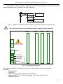
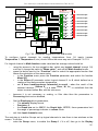
The functionality of MultiCon CMC-99/141 can fit to the user's needs. The base of the
MultiCon CMC-99/141 contains: the main processor, display with touch-screen, Switch Mode
Power Supply (in one of two versions: 19V...24...50V DC 16V...24...35V AC and 85V..230..260V
AC) and basic communication interfaces like USB and RS485. See Fig. 4.8 - most far left
connectors. All other modules are optional and can be installed inside the device according to
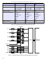
customer's needs. Next to the basic connectors is the slot for an advanced communication
module. In the simplest version this module can be equipped only with rear USB Host
connector (this is standard for the IP-65 version of the MultiCon CMC-99/141). The full
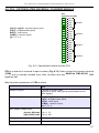
version of this module contains also 2 additional serial ports (RS485 and RS485/RS232) and
a 10Mb Ethernet RJ-45 connector (see Fig. 4.17).
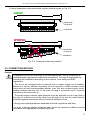
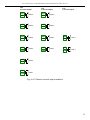
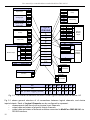
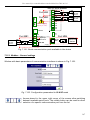
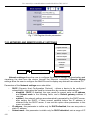
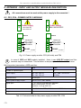
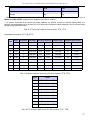
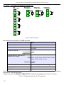
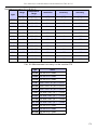
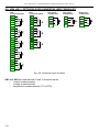
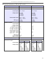
Three slots designed for built-in hardware inputs and outputs are installed on the right
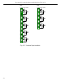
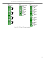
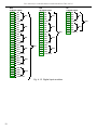
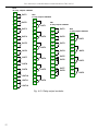
side of the case (see Fig. 4.8, terminals marked: slot A, slot B and slot C). The number and
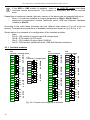
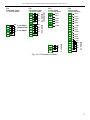
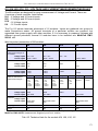
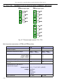
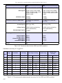
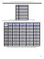
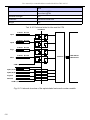
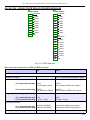
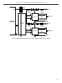
size of these terminals varies depending on module type. Brief descriptions of available
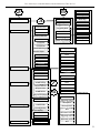
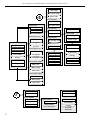
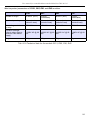
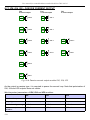
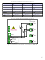
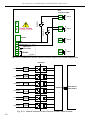
modules are shown in Fig. 4.9-4.17. Measurement and actuator modules are constantly being
developed, so the current list of available modules varies (visit manufacturers website to
check current list of MultiCon CMC-99/141 modules).
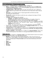
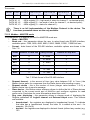
Basic measurement modules are:
– 4/8/16x Voltage/Current input module,
– 4x flowmeter + 4x current input
– 4x RTD input module,
– 4/8x TC input module.
– 8/16/24x Digital input
– 3/5x universal input
– 4x universal counter input
Output modules are:
– 8/16x SSR driver module,
– 8/12x Relay 1A/250V module,
– 4/6x Relay 5A/250V module,
– 2/4/6x IO passive current output.
Communication module:
– ACM - advanced communication module.
6. WORKING WITH THE MultiCon CMC-99/141
6.1. MultiCon CMC-99/141 POWER UP
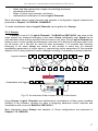
After powering up a starting Logo is showed on the MultiCon CMC-99/141 display.
While the operating system is being loaded a progress bar is visible in the middle of the
screen. During this process the view of screen may stay dimmed for 3-5 seconds. Please wait
until the end of this operation before starting to operate the device. Additionally, in the last
phase of loading in the lower left corner displays the software version. After that the main
application is started. The view of the main program depends of the General settings (see
the Chapter 7.7. GENERAL SETTINGS) and Group settings (see Chapter 7.14. GROUPS).
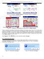
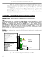
An example view of the main program shown in Fig. 6.1.
28