1
User manual for controller/data recorder MultiCon CMC-99/141
In the next step you need to define five logical channels respectively for four temperatures in
the hall of the symbols A1, A2, A3, A4, and an temperature alarm condition. To do this:
a) For the temperature reading of sensor 1 with the symbol A1:
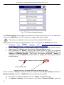
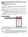
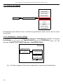
– touch screen and press the Menu button, then press the Device configuration
button and enter the Input channels menu,
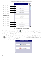
– using the arrows in the top navigation bar, select any logical channel such as 1,
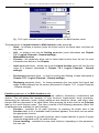
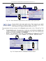
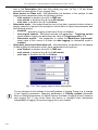
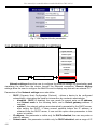
change the name to "Temperature A1" and set the Hardware input mode,
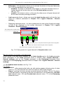
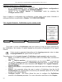
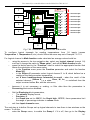
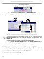
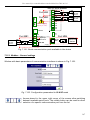
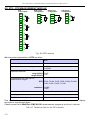
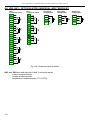
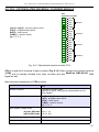
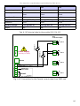
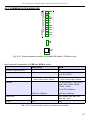
– choose as the source - Inp. A1: Thermocouple (see the connection in Fig. 7.53),
press the Source configuration button to set the source configuration options,
•
The Mode set to Thermocouple K,
•
the Low Limit parameter is set to -200°C,
•
the High Limit parameter is set to 1370°C, the parameters of the High and
Low limit, restrict the range of the input module (total range for the
thermocouple K is -200 ÷ 1370°C), beyond which the display displays the value
of properly -Lo- and -Hi-. After setting the source configuration parameters must
approve the changes and exit from the sub-menu,
– because it is not necessary or scaling, or filter data then the parameters in
Processing block as disabled,
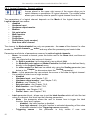
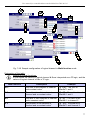
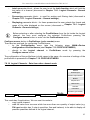
– Set the Display block parameters,
•
The numeric display format,
Precision: 0, because this precision is enough to control the temperature of the
•
Hall,
•
The Graph low set to -200°C, the Graph high: 1370°C, these parameters limit
the range of percentage values in in value mode.
b) For the temperature reading of sensor 2 with the symbol A2:
Proceed the same as for sensor 1, except that:
– Using the arrows in the top navigation bar, select any logical channel (except for 1)
for example 2, change the name to "Temperature A2", and set the hardware input
mode, with the Source - Inp. A2: Thermocouple
Other parameters are set as the sensor 1.
c) For the temperature reading of sensor 3 with the symbol A3:
Proceed the same as for sensor 1, except that:
– Using the arrows in the top navigation bar, select any logical channel (except for 1
and 2) for example 3, change the name to "Temperature A3", and set the
hardware input mode, with the Source - Inp. A3: Thermocouple
Other parameters are set as the sensor 1.
d) For the temperature reading of sensor 4 with the symbol A4:
Proceed the same as for sensor 1, except that:
– Using the arrows in the top navigation bar, select any logical channel (except for 1, 2
and 3) for example 4, change the name to "Temperature A4", and set the hardware
input mode, with the Source - Inp. A4: Thermocouple
Other parameters are set as the sensor 1.
d) For alarm state,
– using the arrows in the top navigation bar, select any logical channel (except for 1, 2,
3 and 4) eg 5, change the name to "Alarm" and set the Math function mode,
– press the button next to the “Function” label to select the appropriate function that
91