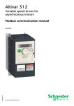
1
This document is based on European standards and is not valid for use in U.S.A. Compact / CANopen / Logic Controller / M238 + Optimized Packaging EIO0000000291 System User Guide MAY 2010 Contents Important Information ................................................................................................................3 Before You Begin..................................................................................................................4 Introduction ................................................................................................................................6 Abbreviations........................................................................................................................7 Glossary ................................................................................................................................8 Application Source Code .....................................................................................................9 Typical Applications...........................................................................................................10 System ......................................................................................................................................11 Architecture.........................................................................................................................11 Installation...........................................................................................................................14 Hardware ..........................................................................................................................................................18 Software ...........................................................................................................................................................34 Communication ...............................................................................................................................................35 Implementation ...................................................................................................................41 Communication ...............................................................................................................................................43 Controller .........................................................................................................................................................45 HMI....................................................................................................................................................................73 Devices.............................................................................................................................................................80 Altivar 312 ...................................................................................................................................................81 Lexium 32A .................................................................................................................................................85 Appendix...................................................................................................................................86 The Packaging Application ................................................................................................86 Application Specifics......................................................................................................................................88 Detailed Component List ...................................................................................................96 Component Protection Classes.......................................................................................100 Environmental Characteristics ........................................................................................100 Component Features........................................................................................................101 Contact....................................................................................................................................106 FEB 2009 Optimized CANopen M238 Schneider Electric 2 Important Information NOTICE Read these instructions carefully, and look at the equipment to become familiar with the device before trying to install, operate, or maintain it. The following special messages may appear throughout this documentation or on the equipment to warn of potential hazards or to call attention to information that clarifies or simplifies a procedure. The addition of this symbol to a Danger or Warning safety label indicates that an electrical hazard exists, which will result in personal injury if the instructions are not followed. This is the safety alert symbol. It is used to alert you to potential personal injury hazards. Obey all safety messages that follow this symbol to avoid possible injury or death. DANGER DANGER indicates an imminently hazardous situation, which, if not avoided, will result in death or serious injury. WARNING WARNING indicates a potentially hazardous situation, which, if not avoided, can result in death, serious injury, or equipment damage. CAUTION CAUTION indicates a potentially hazardous situation, which, if not avoided, can result in injury or equipment damage. PLEASE Electrical equipment should be installed, operated, serviced, and maintained only by qualified personnel. No responsibility is assumed by Schneider Electric for any NOTE consequences arising out of the use of this material. A qualified person is one who has skills and knowledge related to the construction and operation of electrical equipment and the installation, and has received safety training to recognize and avoid the hazards involved © 2008 Schneider Electric. All Rights Reserved. Optimized CANopen M238 Schneider Electric 3 Before You Begin Do not use this product on machinery lacking effective point-of-operation guarding. Lack of effective point-ofoperation guarding on a machine can result in serious injury to the operator of that machine. WARNING UNGUARDED MACHINERY CAN CAUSE SERIOUS INJURY Do not use this software and related automation products on equipment which does not have point-of-operation protection. Do not reach into machine during operation. Failure to follow these instructions can cause death, serious injury or equipment damage. This automation equipment and related software is used to control a variety of industrial processes. The type or model of automation equipment suitable for each application will vary depending on factors such as the control function required, degree of protection required, production methods, unusual conditions, government regulations, etc. In some applications, more than one processor may be required, as when backup redundancy is needed. Only the user can be aware of all the conditions and factors present during setup, operation and maintenance of the machine; therefore, only the user can determine the automation equipment and the related safeties and interlocks which can be properly used. When selecting automation and control equipment and related software for a particular application, the user should refer to the applicable local and national standards and regulations. A “National Safety Council’s” Accident Prevention Manual also provides much useful information. In some applications, such as packaging machinery, additional operator protection such as point-of-operation guarding must be provided. This is necessary if the operator’s hands and other parts of the body are free to enter the pinch points or other hazardous areas and serious injury can occur. Software products by itself cannot protect an operator from injury. For this reason the software cannot be substituted for or take the place of point-ofoperation protection. Ensure that appropriate safeties and mechanical/electrical interlocks for point-of-operation protection have been installed and are operational before placing the equipment into service. All mechanical/electrical interlocks and safeties for point-of-operation protection must be coordinated with the related automation equipment and software programming. NOTE: Coordination of safeties and mechanical/electrical interlocks for point-of-operation protection is outside the scope of this document. START UP AND TEST Before using electrical control and automation equipment for regular operation after installation, the system should be given a start up test by qualified personnel to verify correct operation of the equipment. It is important that arrangements for such a check be made and that enough time is allowed to perform complete and satisfactory testing. Optimized CANopen M238 Schneider Electric 4 CAUTION EQUIPMENT OPERATION HAZARD Verify that all installation and set up procedures have been completed. Before operational tests are performed, remove all blocks or other temporary holding means used for shipment from all component devices. Remove tools, meters and debris from equipment. Failure to follow these instructions can result in injury or equipment damage. Follow all start up tests recommended in the equipment documentation. Store all equipment documentation for future reference. Software testing must be done in both simulated and real environments. Verify that the completed system is free from all short circuits and grounds, except those grounds installed according to local regulations (according to the National Electrical Code in the U.S.A, for instance). If high-potential voltage testing is necessary, follow recommendations in equipment documentation to prevent accidental equipment damage. Before energizing equipment: • Remove tools, meters, and debris from equipment. • Close the equipment enclosure door. • Remove ground from incoming power lines. • Perform all start-up tests recommended by the manufacturer. OPERATION AND ADJUSTMENTS The following precautions are from NEMA Standards Publication ICS 7.1-1995 (English version prevails): Regardless of the care exercised in the design and manufacture of equipment or in the selection and rating of components, there are hazards that can be encountered if such equipment is improperly operated. It is sometimes possible to misadjust the equipment and thus produce unsatisfactory or unsafe operation. Always use the manufacturer’s instructions as a guide for functional adjustments. Personnel who have access to these adjustments should be familiar with the equipment manufacturer’s instructions and the machinery used with the electrical equipment. Only those operational adjustments actually required by the operator should be accessible to the operator. Access to other controls should be restricted to prevent unauthorized changes in operating characteristics. WARNING UNEXPECTED EQUIPMENT OPERATION Only use software tools approved by Schneider Electric for use with this equipment. Update your application program every time you change the physical hardware configuration. Failure to follow these instructions can cause death, serious injury or equipment damage. Optimized CANopen M238 Schneider Electric 5 Introduction Introduction This document is intended to provide a quick introduction to the described System. It is not intended to replace any specific product documentation, nor any of your own design documentation. On the contrary, it offers additional information to the product documentation, for installing, configuring and implementing the system. The architecture described in this document is not a specific product in the normal commercial sense. It describes an example of how Schneider Electric and third-party components may be integrated to fulfill an industrial application. A detailed functional description or the specification for a specific user application is not part of this document. Nevertheless, the document outlines some typical applications where the system might be implemented. The architecture described in this document has been fully tested in our laboratories using all the specific references you will find in the component list near the end of this document. Of course, your specific application requirements may be different and will require additional and/or different components. In this case, you will have to adapt the information provided in this document to your particular needs. To do so, you will need to consult the specific product documentation of the components that you are substituting in this architecture. Pay particular attention in conforming to any safety information, different electrical requirements and normative standards that would apply to your adaptation. It should be noted that there are some major components in the architecture described in this document that cannot be substituted without completely invalidating the architecture, descriptions, instructions, wiring diagrams and compatibility between the various software and hardware components specified herein. You must be aware of the consequences of component substitution in the architecture described in this document as substitutions may impair the compatibility and interoperability of software and hardware. This document describes a generic architecture based on Modicon M238 Logic controller G-Type and a packaging architecture based on Modicon M238 Logic controller S-Type. Optimized CANopen M238 Schneider Electric 6 Abbreviations Abbreviation AC CB CFC DI DO DC DFB EDS E-STOP FBD HMI I/O IL LD PC POU PDO PS RMS RPM RPDO SE SFC SDO ST TPDO TVDA VSD WxHxD Optimized CANopen M238 Signification Alternating Current Circuit Breaker Continuous Function Chart – a programming language based on function chart Digital Input Digital Output Direct Current Derived Function Blocks Electronic Data Sheet Emergency Stop Function Block Diagram – an IEC-61131 programming language Human Machine Interface Input/Output Instruction List - a textual IEC-61131 programming language Ladder Diagram – a graphic IEC-61131 programming language Personal Computer Programmable Object Unit, Program Section in SoMachine Process Data Object (CANopen) Power Supply Root Mean Square Revolution Per Minute Receive Process Data Object (CANopen) Schneider Electric Sequential Function Chart – an IEC-61131 programming language Service Data Object Structured Text – an IEC-61131 programming language Transmit Process Data Object (CANopen) Tested, Validated and Documented Architecture Variable Speed Drive Dimensions : Width, Height and Depth Schneider Electric 7 Glossary Expression Altivar (ATV) CANopen Harmony ILA, ILE Lexium (LXM) Magelis Modicon M238 Logic controller Modbus OsiSense Phaseo PLCopen Preventa SoMachine TeSys Vijeo Designer Optimized CANopen M238 Signification SE product name for a family of VSDs Name for a communications machine bus system SE product name for a family of switches and indicators SE product name for a integrated drive Lexium SE product name for a family of servo drives SE product name for a family of HMI-Devices SE product name for Programmable Logic Controller A Communications protocol SE product name for a family of sensors SE product name for a family of power supplies An international standard for industrial controller programming. SE product name for a family of safety devices SE product name for an integrated software tool SE product name for a family for motor protection devices and load contactors An SE software product for programming Magelis HMI devices Schneider Electric 8 Application Source Code Introduction Examples of the source code and wiring diagrams used to attain the system function as described in this document can be downloaded from our website (registration is required, speak with your Schneider Electric Application Design Expert). The example source code is in the form of configuration, application and import files. Use the appropriate software tool to either open or import the files. Extension CSV DOC DWG EDS PDF PROJECT VDZ Z13 Optimized CANopen M238 File Type Comma Separated Values, Spreadsheet Document file Project file Electronic Data Sheet – Device Definition Portable Document Format - document Project file Project file Project archive file Schneider Electric Software Tool Required MS Excel Microsoft Word AutoCAD Industrial standard Adobe Acrobat SoMachine Vijeo Designer EPLAN 9 Typical Applications Introduction Here you will find a list of the typical applications, and their market segments, where this system or subsystem can be applied: Hoisting Gantry crane Overhead traveling crane Conveying Roller Bed Turn table Transfer Packaging Filling & closing machines Vertical bagging machines Boxing machines Carton closing / erecting machines Shrink Wrapping machines Labeling machines Textile Opening and closing machines Circular knitting machines Plucker machines Blending machines Carding machines Drawing frame machines Combing machines Ring Spinning machines Scouring Bleaching machines Jigger machines Pre shrinking machines Pumping Booster stations Compressors Vacuum pumps Others Winding / Unwinding machines Wood working machines Cutting machines Sander machines Sawing machines Optimized CANopen M238 Schneider Electric 10 System Introduction The system chapter describes the architecture, the dimensions, the quantities and different types of components used within this system. Architecture General The controller in this application is a Modicon M238 Logic controller. The user can control the application using the Magelis HMI device. The VSDs, servo drives and FTBs are connected to the M238 via a CANopen bus. The example application includes two functional safety options according to IEC 61508 standards: an Emergency Stop function supervised by a Preventa safety module (see the appropriate hardware manual), plus a second Preventa safety module to evaluate protective door sensors. Layout Optimized CANopen M238 Schneider Electric 11 Components Hardware: Main switch type Compact NSX100F GV2L motor circuit breaker Altivar 312 variable speed drive with integrated CANopen interface Emergency Stop switch with rotation release (trigger action) Phaseo Power supply ABL8 Modicon M238 Logic Controller Lexium 32A servo drive Advantys FTB I/O island OsiSense (Osicoder) Harmony pushbuttons Preventa XPS safety module TeSysD load contactors Software: SoMachine V2.0 Quantities of Components For a complete and detailed list of components, the quantities required and the order numbers, please refer to the components list at the rear of this document. Degree of Protection Not all the components in this configuration are designed to withstand the same environmental conditions. Some components may need additional protection, such us housings, depending on the environment in which you intend to use them. For environmental details of the individual components please refer to the list in the appendix of this document and the corresponding user manual. Cabinet Technical Data Input Mains voltage Power requirement Cable size Cable connection 400 Vac ~ 11 kW 5 x 2.5 mm² (L1, L2, L3, N, PE) 3 phase + Neutral + Ground Neutral is needed for 230 Vac (Phase and Neutral) Output Motor power ratings 2 asynchronous motors (4 poles:1500 RPM) controlled by ATV312 (0.37 kW) 2 asynchronous motors (4 poles:1500 RPM) controlled by ATV312 (0.75 kW) 2 servo motors (BMH type with brake) controlled by LXM32 (continuous output current : 6 A RMS at 6000 RPM) Optimized CANopen M238 Schneider Electric 12 Functional Safety Notice (EN ISO13849-1 EN IEC62061) The standard and level of functional safety you apply to your application is determined by your system design and the overall extent to which your system may be a hazard to people and machinery. As there are no moving mechanical parts in this application example, category 1 (according to EN13849-1) has been selected as an optional safety level. Whether or not this functional safety category should be applied to your system should be ascertained with a proper risk analysis. This document is not comprehensive for any systems using the given architecture and does not absolve users of their duty to uphold the functional safety requirements with respect to the equipment used in their systems or of compliance with either national or international safety laws or regulations. Emergency Stop Emergency Stop / Emergency Disconnection function This function for stopping in an emergency is a protective measure which compliments the safety functions for the safeguarding of hazardous zones according to prEN ISO 12100-2. Safety Functions Door guarding up to Performance Level (PL) = b, Category 1, Safety Integrity Level (SIL) = 1 Dimensions The dimensions of the individual devices used; controller, drives, power supply, etc. require a housing cabinet size of at least 600 x 1800 x 400 mm (WxHxD). The HMI display, illuminated indicators such as “SYSTEM ON“, “SYSTEM OFF“ or “ACKNOWLEDGE EMERGENCY OFF” as well as the Emergency Stop switch itself, can be built into the door of the cabinet. Optimized CANopen M238 Schneider Electric 13 Installation Introduction This chapter describes the steps necessary to set up the hardware and configure the software required to fulfill the described function of the application. Assembly Main rack H1 Front Optimized CANopen M238 Schneider Electric 14 Main rack H1 Interior Optimized CANopen M238 Schneider Electric 15 Distributed rack H2 Optimized CANopen M238 Schneider Electric 16 Notes The components designed for installation in a cabinet, i.e. the controller, safety modules, circuit breakers, contactors, motor circuit breakers and power supply can be mounted on a 35 mm DIN rail. Main switch, solid state relays, Lexium 32A servo drives and Altivar 312 variable speed drives are screwed directly onto the mounting plate. Alternatively, if an adapter is used the Altivar 312 can be mounted on a DIN rail. The OsiSense (Osicoder) CANopen encoder and the FTB I/O are installed in the field. The Emergency Stop button, the door safety switches and the pushbutton housing for the display and acknowledgement indicators are designed for on-wall mounting in the field. All switches (except the door guard switch) can also be installed directly in a control cabinet (e.g., in a cabinet door) without special housings. There are two options for installing XB5 pushbuttons or indicator lamps: These pushbuttons or switches can be installed either in a 22 mm hole, e.g., drilled into the front door of the control cabinet, or in an XALD-type housing suitable for up to 5 pushbuttons or indicator lamps. The XALD pushbutton housing is designed for backplane assembly or direct wall mounting 400 Vac 3-phase or 230 Vac 1-phase wiring for the motion and drive circuitry (LXM32A and ATV312). 400 Vac 3-phase wiring between the main circuit breaker, drives, motor starters and motors. 230 Vac 1-phase wiring between the main circuit breaker and Lexium servo drives 230 Vac 1-phase wiring between the main circuit breaker and primary side of the 24 Vdc power supply 24 Vdc wiring for the control circuits, the controller’s power supply, the I/O modules and the HMI. The individual components must be interconnected in accordance with the detailed circuit diagram in order to ensure that they function correctly. CANopen cables are installed for the communications link between the controller and the ATV312, LXM32A, OsiSense (Osicoder) and, OTB and FTB I/O modules. Serial line XBTZ9008 cable is installed for the communication link between the controller and the HMI. Optimized CANopen M238 Schneider Electric 17 Hardware General General description of the hardware. Mains Switch Compact NSX100F LV429003 36 kA 380/415 Vac Mains Switch Compact NSX100F LV429035 Trip unit TM32D Thermal-magnetic 32 A Ir - Thermal protection Im - Magnetic protection Mains Switch Compact NSX100F Rotary handle LV429340 Terminal shield LV429515 Rotary handle with red handle on yellow front Terminal shield short Emergency Stop Harmony switch (trigger action) XALK178G Optimized CANopen M238 Schneider Electric 18 Phaseo ABL8RPS24100 Power supply 24 Vdc, 10 A Safety Module Preventa XPSAC5121 Safety Module Preventa XPSAV11113Z002 Optimized CANopen M238 Schneider Electric 19 Preventa Expansion Module XPSECP5131 Motor Circuit Breaker GV2L08 and GV2L14 with auxiliary contact GVAE11 Contactor TeSysD LC1D18BL Optimized CANopen M238 Schneider Electric 20 Modicon M238 Logic controller TM238LFDC24DT 14 Digital Inputs 10 Digital Outputs Optimized CANopen M238 Schneider Electric 21 Modicon M238 Logic controller TM238LFDC24DT 14 Digital Inputs 10 Digital Outputs 1. Mini B USB Port, for a programming terminal. 2. A hinged access cover with 2 cable glands (1 removable for the terminal cord set and 1 for the CANopen cable). 3. The controller status by means of 4 LEDs (PWR, RUN, Batt and Err) and The integrated communication port status by means of 4 LEDs (SL1, SL2,CAN Run and CAN Err.). 4. A display unit showing the I/O states (I0…I13 and Q0…Q9). 5. A removable screw terminal block (12 terminals) for connecting the sensors (24 Vdc fast inputs). 6. A removable screw terminal block (7 terminals) for connecting the sensors (24 Vdc inputs). 7. A connector for discrete TM2 Dpp, analog TM2 App and counter TM200 HSC210Dp I/O extension modules (7 modules max.). 8. A removable screw terminal block (10 terminals) for connecting the 6 pre-actuators (24 V c outputs). 9. A removable screw terminal block (6 terminals) for connecting the 4 pre-actuators (24 V c fast outputs). 10. A removable screw terminal block (5 terminals marked CANopen) for connection to the CANopen bus, with model TM238 LFDC24DT. 11. A non-removable screw terminal block (3 terminals +, -, t marked 24 Vdc) for connecting the 24 Vdc power supply, With access from the underside of the controller. 12. 2 RJ 45 connectors for connection of 2 serial links) marked SL1 and SL2 (Modbus /SoMachine protocol). 13. A hinged cover for accessing the optional backup battery for the RAM memory and the real-time clock inside the base. Optimized CANopen M238 Schneider Electric 22 TM2 I/O Module TM2DMM24DRF 16 Digital Inputs 8 Digital Outputs TM2 I/O Module TM2DDI16DT 16 Digital Inputs TM2 I/O Module TM2DDO8UT 8 Digital Outputs TM2 I/O Module TM2AMM6HT 4 Analog Inputs 2 Analog Outputs TM2 I/O Module TM2AMI4LT 4 Analog Inputs Optimized CANopen M238 Schneider Electric 23 Magelis HMI XBTGT2330 Servo Drive Lexium 32A LXM32AD18M2 1-phase 230 Vac Continuous output current: 6 A RMS at 6000 RPM Servo Drive Lexium 32A LXM32AD18M2 Embedded Human Machine Interface Optimized CANopen M238 Schneider Electric 24 Servo Drive Lexium 32A 1-phase LXM32AD18M2 Wiring diagram Power cable connection to motor (Length 3 m) Servo Drive Lexium 32A 1-phase LXM32AD18M2 Wiring diagram holding brake Servo Drive Lexium 32A 1-phase LXM32AD18M2 Parallel connection DC bus Optimized CANopen M238 Schneider Electric 25 Servo Drive Lexium 32A 1-phase LXM32AD18M2 Connecting the external braking resistor Servo Drive Lexium 32A 1-phase LXM32AD18M2 Wiring diagram power stage supply voltage for 1-phase device Optimized CANopen M238 Schneider Electric 26 Servo Drive Lexium 32A 1-phase LXM32AD18M2 Wiring diagram motor encoder Optimized CANopen M238 Schneider Electric 27 Servo Drive Lexium 32A 1-phase LXM32AD18M2 Wiring diagram controller supply voltage Optimized CANopen M238 Schneider Electric 28 Servo Drive Lexium 32A 1-phase LXM32AD18M2 Wiring diagram, digital inputs/outputs Servo motor BMH0702T02F2A with brake Optimized CANopen M238 Schneider Electric 29 Variable Speed Drives Altivar 312 ATV312H037N4 3-phase 400 Vac, 0.37kW and ATV312H075N4 3-phase 400 Vac, 0.75 kW I/O- Module IP67 Advantys FTB FTB1CN08E08SPO 8 Inputs 8 Outputs Optimized CANopen M238 Schneider Electric 30 Power Supply Cable Advantys FTB FTXDP2210 The FTB power supply cables are linked in line from one module to the next. PIN Signal Cable 1 0V 1 2 0V 2 3 PE Green/Yellow 4 +24 Vdc DI 3 5 +24 Vdc DO 4 Tower Light Harmony XVBC Red Steady LED XVBC2B4 Green Steady LED XVBC2B3 Blue Steady LED XVBC2B6 White Steady LED XVBC2B7 Solid state relay SSRPCDS10A1 Input: Output: Optimized CANopen M238 3 … 32 Vdc 24 … 280 Vac 10 A Schneider Electric 31 CANopen multi-turn absolute encoder OsiSense (Osicoder) XCC3510PS84CB Photoelectric Sensor OsiSense XUB1APANM12 with Reflector XUZC50 Inductive Proximity Sensor OsiSense XS608B1PAM12 Cable for photo barriers and proximity sensor OsiSense XZCP1264L2 Only 1x M12 connector for sensor: other side must be extended with connector XZCC12FDM40B Optimized CANopen M238 Schneider Electric 32 Sensor for Temperature Measurement Pt100 PT46X150 Optimized CANopen M238 Schneider Electric 33 Software General The main programming work lies in programming the Modicon M238 Logic controller, the configuration of the CANopen fieldbus and creating the screens for the HMI display. Programming the Modicon M238 Logic controller is done using SoMachine. Programming of the Magelis XBTGT 2330 HMI is done by using Vijeo Designer which is integrated into SoMachine. Configuration of the drives (ATV312 and LXM32A) is done using the control panel on the drive To use the software packages, your PC must have the appropriate Microsoft Windows operating system installed: Windows XP Professional The software tools have the following default install paths: SoMachine C:\Program Files\Schneider Electric\SoMachine Vijeo Designer C:\Programs\Schneider Electric\VijeoDesigner Optimized CANopen M238 Schneider Electric 34 Communication General The TVDA architecture includes two different communication networks. The CANopen field bus connects the Modicon M238 Logic controller as CANopen Master, Altivar drives, Advantys FTB I/O and Lexium 32A servo drives as CANopen slave nodes. All the drives and the I/O-Island are connected to the CANopen via CANopen TAPs. The CANopen transmission rate is 500 kb/s. The Modicon M238 Logic controller and the Magelis XBTGT HMI communicate via SoMachine protocol. The download from the PC to the M238 and to the HMI is done using a single connection. The PC has to be connected to the HMI. Using this connection the data is also sent across to the M238. The local control panel is used to configure the ATV312 and the LXM32A. PC ↔ XBTGT ↔ M238 The download direction is from the PC to the HMI and via the HMI to the M238 Note: For a direct connection from the PC to the controller the TCSXCNAMUM3P cable can be used. 1. PC 2. Magelis XBTGT HMI 3. Modicon M238 Logic controller 4. USB to USB cable XBTZG935 5. SubD9 to RJ45 cable XBTZ9008 Optimized CANopen M238 Schneider Electric 35 Controller ↔ HMI XBTZ9008 Cable for connecting an XBTGT and an M238 Logic controller PC ↔ HMI PC connection cable XBTZG935 Cable for the connection between a SoMachineequipped PC and XBTGT Altivar 312 Modbus/CANopen networks RJ45 connector Node ID: 1, 2, 3 and 4 for each of the four ATV312. Note: In case of CANopen, the CANopen Tap TSXCANTDM4 is used to connect the variable speed drive to the CANopen bus via RJ45 socket. Optimized CANopen M238 Schneider Electric 36 CANopen connection Lexium 32A Node ID: 5 and 6 Pin Signal Meaning I/O 1. CAN_H CAN interface CAN level 2. CAN_L CAN interface CAN level 3. CAN_0V Reference potential CAN 4. nc not used 5. nc not used 6. nc not used 7. nc not used - 8. nc not used - Optimized CANopen M238 Schneider Electric 37 Advantys FTB FTB1CN08E08SPO Node ID: 11,12,13 and 14 Baudrate Position 7 500 kbps CANopen TAP TSXCANTDM4 4 port CANopen junction box For the purpose of this application, the sliding switch should be set to OFF if it is not at the end of the CANopen line. Optimized CANopen M238 Schneider Electric 38 CANopen TAP TSXCANTDM4 Note: When using devices which require a 24 Vdc power supply on CANopen line (such as TeSysU) the 24 Vdc power must be wired. Power supply: V+1 CG1 24 Vdc 0 Vdc CANopen preassembled connection cable TCSCCN4F3M1T (length: 1.0 m) Used for connection between ATV312 or LXM32A with TSXCANTDM4. CANopen cable TSXCANCxy The cable is available in various versions (x): A - Standard B - No Flame D - Heavy Duty and various lengths (y): 50 - for 50 m 100 - for 100 m, 300 - for 300 m. Optimized CANopen M238 Schneider Electric 39 CANopen preassembled connection cable FTXCN32xx PIN 1 2 3 4 5 Used for the connection between the racks and the field devices. Signal Shield V+ GND CAN_H CAN_L Colour Red black White Blue OsiSense (Osicoder) CANopen multi-turn absolute encoder XCC3510PS84CB Baudrate Position 5 500 kbps Node ID : 15 Optimized CANopen M238 Schneider Electric 40 Implementation Introduction The implementation chapter describes all the steps necessary to initialize, to configure, to program and start-up the system to achieve the application functions as listed below. Function Start up and functional description 1. Ensure all motor circuit breakers and Multi9 circuit breakers are in the ON position. 2. Ensure that the mains switch is in the ON position. 3. Press the "ACKN E-STOP" blue illuminated pushbutton on the main cabinet door to acknowledge the system is energized. The blue illuminated pushbutton will turn OFF if the system is energized. 4. Ensure that all machine interlocks are engaged (i.e. the door guard switches) 5. Press the "ACKN DOOR-READY" blue illuminated pushbutton on the main cabinet door to acknowledge the system is ready for operation. The blue illuminated pushbutton will turn OFF if the system is ready for operation. 6. Use Magelis XBT HMI to control/monitor the system. a. The “BUS”, “ALARMS”, “SAFETY” screens can be used to monitor the network, system status and alarm messages. b. The “ATV312” screen can be used to control/monitor Altivar 312 variable speed drives. c. The “LXM32” screen can be used to control/monitor Lexium 32 servo drives. d. The “FTB” screen can be used to observe the status of the field I/O. Functional Layout Optimized CANopen M238 Schneider Electric 41 Course of Action Flow chart showing the implementation procedure Optimized CANopen M238 Schneider Electric 42 Communication Introduction This chapter describes the data passed via the communications field bus and network (e.g. CANopen or Ethernet) that are not bound directly with digital or analog hardware. The list contains: Device Links The device links Direction of data flow Symbolic name and Bus address of the device concerned. This application uses CANopen fieldbus. CANopen connects the following devices: 1 Modicon M238 Logic Controller on bus address 127 4 Altivar 312 variable speed drives, bus addresses 1,2,3 and 4. 2 Lexium 32A servo drives, bus addresses 5 and 6 4 Advantys FTB I/O island, bus addresses 11, 12, 13 and 14. 1 OsiSense (Osicoder) CANopen encoder, bus address 15 The used CANopen Baudrate is 500kBit/s The SoMachine protocol over serial port (RS485) connects: Magelis XBTGT HMI Modicon M238 Logic controller CANopen nodes main rack CANopen nodes remote racks Optimized CANopen M238 Schneider Electric 43 NOTE Datalink FTB_Node11 <> M238 For the data exchange between the controller and the Lexium 32A and the Altivar 312, PLCopen function blocks are used. It is not necessary to configure the data exchange manually. M238 (CANopen-Master, #127) FTB (CANopen-Slave #11) Data Direction FTB -> M238 Name Designation usiFTB_Node11_Iput Input data of FTB Data Direction M238-> FTB Name Designation usiFTB_Node11_Oput Datalink FTB_Node12 <> M238 Output data of FTB M238(CANopen-Master, #127) FTB (CANopen-Slave #12) Data Direction FTB -> M238 Name Designation usiFTB_Node12_Iput Input data of FTB Data Direction M238-> FTB Name Designation usiFTB_Node12_Oput Datalink FTB_Node13 <> M238 Output data of FTB M238(CANopen-Master, #127) FTB (CANopen-Slave #13) Data Direction FTB -> M238 Name Designation usiFTB_Node13_Iput Input data of FTB Data Direction M238 -> FTB Name Designation usiFTB_Node13_Oput Datalink FTB_Node14 <> M238 Output data of FTB M238(CANopen-Master, #127) FTB (CANopen-Slave #14) Data Direction FTB -> M238 Name Designation usiFTB_Node14_Iput Input data of FTB Data Direction M238 -> FTB Name Designation usiFTB_Node14_Oput Datalink Osicoder_Node 15 <> M238 Output data of FTB M238(CANopen-Master, #127) Osicoder (CANopen-Slave #15) Data Direction Osicoder -> M238 Name udiEncoPosL Optimized CANopen M238 Designation Actual encoder value Schneider Electric 44 Controller Introduction The Controller chapter describes the steps required for the initialization and configuration and the source program required to fulfill the functions. Requirements SoMachine is installed on your PC The Modicon M238 Logic controller is switched on and running The M238 is connected to the HMI with the programming cable XBTZ9008 (M238 to HMI) The HMI is connected to the PC via the cable XBTZG935 (HMI to PC) Setting up the M238 is done as follows: Create a new Project 1 Create a new Project Add the controller Add Expansion Cards Add the CANopen fieldbus Add CANopen devices ATV312 CANopen configuration LXM32 CANopen configuration FTB CANopen Configuration OsiSense (Osicoder) CANopen configuration Add POU Task configuration Add Vijeo Designer HMI Configure controller ↔ HMI data exchange Communication setting Controller ↔ PC Communication setting PC ↔ HMI Save the Project Build Application Download the controller and HMI program Login to the controller Application overview To create a new project select Create new machine→ Start with empty project Optimized CANopen M238 Schneider Electric 45 2 In the Save Project As dialog enter a File name and click on Save. Note: As a default the project is saved under My Documents. 3 4 Add the Controller 1 The SoMachine User Interface opens. Select the Program tab Right click on: Optimized_CANopen_M238 Select Add Device… in the pop-up menu. Optimized CANopen M238 Schneider Electric 46 2 Select Schneider Electric as Vendor. Then select: Logic Controller -> TM238LFDC24DT as device. Click on Add Device Add Expansion Cards 3 The Devices browser now displays the new controller. 1 To add an expansion card, right click on MyController (TM238LFDC24DT) and click on Add Device... Optimized CANopen M238 Schneider Electric 47 2 Select the expansion card and click on Add Device For this project add the following cards: 2x TM2DMM24DRF 1x TM2DDI16DT 2x TM2DDO8UT 1x TM2AMM6HT 1x TM2AMI4LT Once you have added all the cards close the dialog. 3 The added expansion cards can now be seen at the end of the device list. Optimized CANopen M238 Schneider Electric 48 4 To edit an expansion card, click on it. Here we will edit the Pt100 expansion card TM2AMI4LT 5 Select the I/O Configuration tab. 6 Change the Value of the Enumeration of BYTE for Mode of the IW0 to Temperature and the Enumeration of BYTE for Type to PT100 Optimized CANopen M238 Schneider Electric 49 7 On the Extension Bus I/O Mapping tab it is possible to map the data of IW0, IW1, IW2 and IW3 to variables. 8 There are two ways of Mapping: 1.Mapping to an existing variable 2.Create a new variable In this project Create a new variable was chosen. This method allows SoMachine to create a global variable which can be used throughout the whole program. The names of the variables can be entered in the Variable field. To update the variables with the newest I/O data check Always update variables. Add the CANopen fieldbus 1 Right click on CAN and select: Add Device... Optimized CANopen M238 Schneider Electric 50 2 Select: CANopen_Optimized Click on Add Device 3 Add CANopen Devices To activate the Heartbeat of the M238 double click the CANopen_Optimized and check Enable heartbeat generation. 4 The Heartbeat time is 200 ms. To set the Baudrate of the CANopen bus, double click on CAN and select 500000 as a Baudrate. 1 Right click on the CANopen_Optimized and select Add Device… in the pop-up menu. Optimized CANopen M238 Schneider Electric 51 2 Select the device that you wish to connect to the CANopen bus. In this project the following devices are connected to the CANopen bus: 4x Altivar 312 2x Lexium 32A 4x FTB 1CN08E08SP0 1x Osicoder Add each device by clicking on Add Device. Once you have added all devices click on Close. Note: The name of the device can be changed under Name. 3 The new devices are now listed in CANopen_Optimized. To configure the devices, double click on the specific item. The name of each device can be changed. ATV312 CANopen configuration 1 Double click on the ATV_312_Node_1 Note: In this project all PDO settings remain at their defaults. Set the Node Id to 1 (for the second ATV to 2, third ATV to 3, and forth to 4). Optimized CANopen M238 Schneider Electric 52 2 To change the name of the CANopen device, click on the old name. Note: The name of the device is also the AXIS REF name for the PLCopen functions used in the application program LXM32 CANopen configuration 1 The configuration is done in the same way as the ATV312 configuration. The only difference is the CANopen (5 and 6) address. FTB CANopen configuration 1 To configure the FTB double click on FTB 1CN08E08SP0. 2 Select Node ID as 11. The node ID for other 3 FTBs are 12,13 and 14 3 Go to the PDO Mapping tab and checkmark the first Transmit PDO (16#1800) and Receive PDO (16#1400) Optimized CANopen M238 Schneider Electric 53 4 In the CANopen I/O Mapping tab, the OTB inputs and outputs are mapped to variables. There are two ways of Mapping: 1.Mapping to an existing variable 2.Creating a new variable In this project create a new variable was chosen. This method allows SoMachine to create a global variable which can be used throughout the whole program. The names of the variables can be entered in the Variable field. 5 To change the standard setting of the PIN2 input from diagnostic to normal input, go to the Service Data Object tab… and click New… Select the SDO 16#2000/01 and set the Value to 0. Press OK. In the Service Data Object tab is now the new SDO. Optimized CANopen M238 Schneider Electric 54 Osicoder CANopen configuration 6 Click on the CANopen I/O Mapping tab and check Always Update variables. 1 To configure the Osicoder double click on Osicoder_Node_15. 2 Select Node ID 15 3 Go to the PDO Mapping tab and double click the TxPDO1 4 Set the Event Time to a value greater 0. In this project it is 50 ms. If the value is 0, the Osicoder will not send any data. Optimized CANopen M238 Schneider Electric 55 5 In the CANopen I/O Mapping tab, the OTB inputs and outputs are mapped to variables. There are two ways of Mapping: 1.Mapping to an existing variable 2.Creating a new variable In this project create a new variable was selected. This method allows SoMachine create a global variable which can be used throughout the whole program. The names of the variables can be entered in the Variable field. Add a POU 6 Click on the CANopen I/O Mapping tab and check Always Update variables. 1 In the project browser, right click on: Application→Add Object... 2 Select POU and enter a Name. As Type select Program and as Implementation language select CFC. It is possible to select all the IEC languages and to generate functions and function blocks. Click on Open. Optimized CANopen M238 Schneider Electric 56 3 4 The new POU LXM32A_OPER is now visible under Application. Double click on LXM32A_OPER to open it. The upper frame displays the declaration section. The lower frame is for programming. On the right side is the ToolBox window. Use drag and drop with the toolbox to place example templates in the programming section. 5 Once you have placed a template in the programming section click on the ??? 6 Type in a name for the function or function block. When the first letters are typed a pop-up menu opens with hints for the name. 7 8 In this project example an MC_POWER_LXM FB was selected. The MC_POWER_LXM FB powers on the LXM32A servo drive. To instantiate the FB click the ??? … and type in a name (for example LXM_32A_Node_5_Power). Now press Enter. The Auto Declare dialog opens. Here click on OK to create the instance. Note: If you wish to add a comment you can do this in the Comment box. Optimized CANopen M238 Schneider Electric 57 9 The new FB MC_POWER_LXM is instantiated in the declaration section of the LXM32A_OPER. 10 To connect a variable to an input place an input field from the ToolBox on the input side of the FB and connect the input box to the FB input by clicking on the red field and dragging it to the input of the FB. Click the input field and press F8. 11 The Input Assistant is displayed. 12 In the Input Assistant select Categories as Global Variables. In the items select MyController→ PLC Logic(MyController) → Application(MyController: PLC Logic) → GVL And then the variable. In this project the variable is the name of one of the LXM32A. 13 Click on OK. This image shows the FB with the connected input. The name of the axis can also be directly written at the input as ”LXM_32A_Node_5” Optimized CANopen M238 Schneider Electric 58 Task Configuration 14 Output selection is similar to input definition, but here we create a new variable. Click the output field, type in the name of the variable and press Enter. In the Auto Declare dialog select the Scope, the Name and the Type. In this example VAR_GLOBAL is selected as Scope. When finished click on OK. 15 The VAR_GLOBAL variables are located in the GVL folder. All variables located in this folder can be accessed throughout the whole Application. If the variables are located in the POU, they can only be accessed by the POU (local variables). 1 Before you can start working with the new POU you have to add it to a task. Here, the POUs are added to the MAST task. To do this double click the MAST task and click on Add POU. Note: If a POU is not included in a TASK, or added to another POU, which is cyclically invoked, it will not be cyclically invoked. 2 Select Categories Programs (Project) and select the new POU in the Items list. Then click OK. Optimized CANopen M238 Schneider Electric 59 3 Now the POU is in the MAST task. In the upper part of the MAST task configuration you can change the Type of the task. In this project it is Freewheeling. Direct under the Type menu is the Watchdog field. Set the Watchdog Time to 100ms. Add Vijeo Designer HMI 1 To add a Vijeo Designer HMI unit to the project right click on Optimized_CANopen_M238 → Add Device… 2 In the Add Device dialog select Device and select Schneider Electric as Vendor. Click on: Magelis HMI-> XBTGT 2000 Series-> XBTGT2330-2930. Click on Add Device Optimized CANopen M238 Schneider Electric 60 3 The new XBTGT2330_2930 is now listed in the configuration. Note: With this XBTGT2330_2930, the Program Vijeo Designer opens and you can start programming. (See chapter HMI) Configure Controller ↔ HMI Data Exchange 1 Right click on: Application→Add Object… 2 Select Symbol configuration in the Add Object dialog. Click on Open. 3 Click on Refresh in the now open Symbol configuration. Optimized CANopen M238 Schneider Electric 61 4 All Variables created in the user program are shown in the Available variables list. In this project all variables are global variables and are located in the GVL folder. To export variables to the HMI, select them and click on >. 5 The right frame lists the Selected variables which are to be used in the HMI. 6 To export the selected variables to Vijeo Designer right click on HMI Application and select Export Symbols to Vijeo-Designer. Communication 1 setting Controller ↔PC To configure the communication gateway double click on MyController (TM238LFDC24DT) in the project browser. Optimized CANopen M238 Schneider Electric 62 2 On the Communication Settings tab click on: Add gateway... 3 Keep the default settings and click on OK. 4 Select Gateway-1 and click on Scan Network. 5 When the scan is finished, the devices pop up under the gateway. Select the M238 used and click Set active path. Optimized CANopen M238 Schneider Electric 63 6 A warning pop-up window opens and the text must be read. 7 The M238 used is now marked as active. 8 NOTE: Every M238 has a unique Serial Number that is a part of the default Device Name. If you would like to change the default Device Name of your controller: click on Edit… In the displayed pop-up window go to the Device Name field and enter the new unique name for your controller. In our example we keep the factory setting name. Optimized CANopen M238 Schneider Electric 64 Communication 1 Setting HMI ↔ PC To configure the communication gateway double click on XBTGT2330_2930 in the project browser. 2 On the tab Communication Settings, click on Add gateway… 3 Retain the default values and click OK. Optimized CANopen M238 Schneider Electric 65 Save the Project 4 Select Gateway-1 and click Scan network 5 When the scan is finished, the devices pop up under the gateway. Select the HMI used and click on Set active path. 6 A warning pop-up window opens and the text must be read. 7 The HMI used is now marked as active. 1 To save the project and change the name select: File->Save Project As… Optimized CANopen M238 Schneider Electric 66 2 Enter the File name and click on Save. Note: By default the project is saved under My Documents. Build Application 1 To build the application click on Build→Build ‘Application [MyController: PLC Logic]’. 2 Note: If you wish to build the whole project (HMI and controller) click Build all After the build you are notified in the Messages field as to whether the build was successful or not. If the build was not successful there will be a list of compilation errors that you must remedy in the Messages field. Download the controller and HMI projects 1 NOTE: If it is the first time you are connecting to the HMI you have to first download the latest runtime version to the HMI using Vijeo Designer. This first download is described in the following steps. If this is not the first download go directly to step 7 Optimized CANopen M238 Schneider Electric 67 2 In Vijeo Designer select the HMI in the device list. Then in the Property Inspector select Download via USB. Note: The PC must be connected to the HMI via the cable XBTZG935. 3 Select: Build→ Download All Optimized CANopen M238 Schneider Electric 68 4 The VDPLoad dialog indicates that the runtime versions does not match. Start the download of the new version by clicking on Yes. 5 The progress of the download is indicated. 6 Once the download is complete, change the Download connection in the Property Inspector back to SoMachine. 7 To download the application to the controller and the HMI Select Online → Multiple Download… Optimized CANopen M238 Schneider Electric 69 8 Check the MyController and the HMI XBTGT2330_2930 and check Always perform a full download. click on OK. 9 Click Yes if you want to do so 10 Before the download starts a build of the complete project is done. The result of the build is displayed in the message window. 11 The results of the download to the controller are displayed in the Multiple Download – Result window. Click on Close to close to the results window. Login to Controller 1 To login to the controller click Online→ Login Optimized CANopen M238 Schneider Electric 70 2 3 4 If the controller program is different from the program on the PC a message asks you if you wish to replace the old controller program. If you do not wish to replace the controller program continue with step 6, otherwise click Yes to confirm the download. The actual download status is displayed at the bottom of the main window. Here you can select to create a boot project if you wish. A boot project is stored in EPROM so that a power loss does not mean you have to repeat the download on restart. 5 Select Yes to create a boot application. The actual creation status is displayed at the bottom of the main window 6 To start the new Application select Online→ Start 7 If you want to start the application click Yes. Optimized CANopen M238 Schneider Electric 71 Application overview 8 If everything is operating properly, the devices and folders are marked in green otherwise they will be marked in red. 1 The picture on the right shows the structure of the program. Every POU has its own entry in the structure. All of these POUs have different functions. These functions are, for example, for drive controlling etc. Additionally there are POUs for bus state and status LED. Optimized CANopen M238 Schneider Electric 72 HMI Introduction This application uses a Magelis XBTGT2330 HMI. This HMI device communicates via the SoMachine protocol with the controller. The HMI is programmed using the software tool Vijeo Designer (Delivered with SoMachine), described briefly in the following pages. For the connection between the PC and the HMI Controller use the cable XBTZG935. NOTE: The Vijeo Designer tool is opened and closed via SoMachine software. For more information see the chapter Controller: Add Vijeo Designer HMI Setting up the HMI is done as follows: Main Window Communication settings Create a switch Create a numeric display Example screens Main Window 1 After double clicking on HMI application in SoMachine, Vijeo Designer creates the HMI program main window. Communication settings 1 To set the communication parameters go in the Navigator to IO Manager → SoMachineNetwork01 → double click on SOM_MyController Optimized CANopen M238 Schneider Electric 73 2 In the dialog window, set the controller Equipment Address. You will find this address in SoMachine… (see next step) 3 … by double clicking on MyController in the devices browser. 4 In the Communication Settings tab select the controller and click on Edit. 5 The Equipment Address of the controller is displayed as the Device Name Optimized CANopen M238 Schneider Electric 74 Create a switch 1 Select the Switch icon in the Tool bar 2 Select the position and dimension where you wish to place the button by opening a rectangle on the display and pressing enter. 3 In the Switch Settings dialog, select the variable that should be linked (bulb icon) to the button. 4 Click on the bulb icon (as indicated in the image above) to open the Variables List dialog. Select the required variable and click OK. Optimized CANopen M238 Schneider Electric 75 5 Go to the Label tab. Here select Label Type: Static and enter a name for the button, e.g. enable. Once you have finished your settings click on OK. Create a Numeric Display 6 The display now shows the new switch. 1 Click on the Numeric Display icon in the tool bar. 2 Select the spot where you want to position the display by opening the rectangle and pressing Enter. Optimized CANopen M238 Schneider Electric 76 3 In the Numeric Display Settings dialog go to the General tab. In Display Digits you can set the maximum number of the digits to be displayed for both integral and fractional part of the value. To link a Variable to the display click on the bulb icon to browse for a variable. Press OK. Example screens 4 The display shows the new numeric display. 1 The Bus page shows the CANopen bus status. 2 The Alarms page shows if an alarm from the device is present. Optimized CANopen M238 Schneider Electric 77 3 The “Safety” page shows the status of the Emergency Stop relay. 4 Via the LXM32A page it is possible control to control LXM32A 5 Via the ATV312 page it is possible control to control ATV312. 6 The FTB/IO page shows the status of the input and output bits of the device. Optimized CANopen M238 Schneider Electric 78 7 The Home page of the HMI shows a picture of the main rack Optimized CANopen M238 Schneider Electric 79 Devices Introduction This chapter describes the steps required to initialize and configure the different devices required to attain the described system function. General Altivar 312 and Lexium 32A drives are configured by using the local control panel. Note It is recommended that the controller is in stop mode before parameterizing the drives. Optimized CANopen M238 Schneider Electric 80 Altivar 312 Introduction The ATV312 parameters can be entered or modified via the local control panel on the front of the device. Note If this is not a new drive it is recommended to return to the factory settings. If you need instructions on how to do this, please read the drive documentation. Jog dial that is a part of the local control panel and can be used for navigation by turning it clockwise or counter-clockwise. Pressing the jog dial enables the user to make a selection or confirm information Control panel 1 The CANopen-Address and Baud rate can be input using the buttons and the jog dial on the control panel of the Altivar. Optimized CANopen M238 Schneider Electric 81 CANopen settings 1 Using the buttons on the front panel, select the sub-menu Communication. 2 In the Communication (COM) sub-menu input the CANopen address in the parameter AdC0. In the example application the addresses for the four drives are 1 to 4. 3 Also in the Communication (COM) sub-menu, in the parameter BdC0, set the Baud rate to 500.0 (kBits). 4 For the ATV312 to operate with the new parameters, a power cycle (on, off, on) is required. Optimized CANopen M238 Schneider Electric 82 Changing the Access Level LAC 1 To set the parameters for the brake function a higher access level (L3) is required. 2 To go to expert mode L3: Select CtL [COMMAND] and press enter Select LAC [ACCESS LEVEL] and press enter L1 (Level 1) is displayed Select L3 (Level 3) and press enter for 2 seconds to set the new level. Return to the LAC with ESC. Return to the CtL with ESC. Optimized CANopen M238 Schneider Electric 83 Brake settings 1 The r2 relay output is used for brake control. 2 To assign the r2 relay output : Select FUn [APPLICATION FUNCT.] and press enter Select bLC- [BRAKE LOGIC CONTROL] and press enter Select bLC [BRAKE LOGIC CONTROL] and press enter Select r2 and press enter. Set the parameters to the values shown here on the right. Note: These parameters are for the test machine only. They are NOT VALID for every machine. After all parameters are set return to the bLC with ESC. Return to the bLC- with ESC. Return to the FUn with ESC. Optimized CANopen M238 Schneider Electric 84 Lexium 32A Introduction The LXM32A parameters can be entered or modified via using the local control panel on the front of the device. Note: If this is not a brand new drive it is recommended to return to the factory settings. If you need instructions on how to do this, please refer to the drive documentation CANopen settings 1 If the drive is being started for the first time, the FSu (First Setup) is invoked. Only the CANopen address (CoAd) and the baud rate (Cobd) is initially needed. If the drive has never been started before, follow the steps below to change the address or the baud rate. In this project the CANopen address for the drives are 5 and 6. The Baud rate for the drives is 500 kBaud. Optimized CANopen M238 Schneider Electric 85 Appendix The Packaging Application Introduction Different machines and processes share the same initial requirements that can be implemented with a generic architecture employing the current Schneider Electric product offer. These generic architectures include power supply, controller, motion, visual indication, communication and safety aspects. The use of these generic architectures to implement customer solutions covers not only covers a large section of customer automation requirements but allows the implementation of a tested and validated software and hardware solution. This chapter describes the Schneider Electric packaging application function blocks used in this architecture. This document does not provide a functional description for the application solution. The functions listed here are not comprehensive and form only a foundation for real life applications. It is not intended to provide an application that fulfills a real life situation in all aspects. For a comprehensive description of the function blocks please refer to the library and function block documentation. The information given here is intended to support the user in the assembly, configuration and implementation of the described solution. The information provided here is additional information to the product documentation, with a focus on the specific components used in the solution provided here. It is expected that the reader has at least a basic knowledge of the industrial application for which this solution is provided and understands the professional jargon normally used in that type of application. This document is not an introduction into the specific type of industrial application for which this solution is provided. Note : The packaging application function blocks can only be used with S-type controllers. If you use G-type controllers, the message "Use of <Name of FB> is not authorized with the current type of device" appears during the build phase. Optimized CANopen M238 Schneider Electric 86 Application Basics The solution described in this document is provided for packaging applications which may consist of the following three machine types: Primary machines These machines work in direct contact with the products to be packaged: Horizontal bagging machines Vertical bagging machines Flexible package form, fill & seal machines Rigid package fill and close machines Blister fill and seal machine Filling and closing machines o o o o o o Secondary machines Secondary machines are linked to products that are required to pack the primary product and any accessories that must be combined in the package: Boxing and carton machines Wrapping machines (sleeve, wrap-around, shrink) Palletizing / de-palletizing machines Pallet securing (stripping, shrink wrapping, stretch ...) o o o o Others Machines not linked to packaging functions but are part of the packaging process: o o o o o o o o o Optimized CANopen M238 Labeling Marking Decorating Cleaning machines Feeding machines and systems Rinsing & washing machines Cooling machines Drying machines Testing & inspection machines Schneider Electric 87 Application Specifics Application Dedicated Hardware General description of the hardware Modicon M238 Logic controller S-Type TM238LFDC24DTS0 14 Digital Inputs 10 Digital Outputs OsiSense (Osiprox) Inductive proximity sensor XS612B1PAL2 Pre-cabled (L = 2 m) for Digital Tension Control OsiSense (Osiprox) Inductive proximity sensor XS508B1PBM8 for Pick and Place with cable XZCP0166L5 Optimized CANopen M238 Schneider Electric 88 OsiSense (Osiprox) Inductive proximity sensor XS4P12AB120 4…20 mA Pre-cabled (L = 2 m) for Analog Tension Control OsiSense (Neptune) Photo-electric sensor XUYFANEP40015 for Lateral Position Control with cable XZCP0941L5 Optimized CANopen M238 Schneider Electric 89 Application Function Blocks To facilitate the software engineering tasks associated with the application described, Schneider Electric has developed the Packaging Application Function Block Library that has been tested and validated. The following pages list the application function blocks that are implemented in the architecture described here. The Packaging and the Toolbox libraries need to be included in the application program (See the chapter Controller: Include new library file) For additional information concerning the packaging AFB’s please refer to the SoMachine help. The following is a list of packaging functions which are running on the Optimized CANopen M238 architecture: Optimized CANopen M238 AnalogTensionControlATV DigitalTensionControlATV LateralPositionControl TemperatureControl XYPickAndPlace MoveJog Schneider Electric 90 FB AnalogTensionControlATV The goal of this Application Function Block is to maintain the tension of the film between two points. This is achieved by controlling the position of the arm dancer. This Application Function Block is the link between a slave axis and a master axis via an analog sensor. AnalogTensionControl setup Optimized CANopen M238 Schneider Electric 91 FB DigitalTensionControlATV The goal of this Application Function Block template is to maintain the tension of the film between two limits. This is achieved by controlling the position of the arm dancer. This Application Function Block provides the coupling between a slave axis and a master axis using a digital sensor. DigitalTensionControl setup Optimized CANopen M238 Schneider Electric 92 FB LateralPositionControl This block controls and corrects the lateral positioning of a film while it is unwinding from a reel. This function helps the “cutting device” to cut film at the correct position. The correction is based on fixing the edges of the film between two digital sensors. If the lateral film position is in good (e.g. between SensorLeft and SensorRight), the path is not corrected. If, however, depending on sensor configuration, the film position is incorrect, it must be corrected. One can select between digital or analog output mode. In this architecture digital output is used. LateralPositionControl setup Optimized CANopen M238 Schneider Electric 93 FB TemperatureControl The function block TemperatureControl is designed for monitoring and controlling a wide variety of temperature-dependent processes. Main characteristics Auto-Tuning or Self-Tuning based on inflectional tangential method Pulse width modulation output for controlling switching actuators Standby function Filtering functions for analogue sensor input Set point ramping function Tolerance band monitoring (two different tolerance bands) Absolute value monitoring Commissioning screens TemperatureControl setup Optimized CANopen M238 Schneider Electric 94 FB XYPickAndPlace The goal of the Application Function Block is to control two linear axis which move manufactured parts from one assembly station to another station or from conveyor to pallet. FB MoveJog The goal of the Application Function Block is to run an axis in speed mode, position mode or to home an axis. PickAndPlace setup Optimized CANopen M238 Schneider Electric 95 Detailed Component List The following is a list of components for the main components of the Optimized CANopen M238 architecture. A complete component list for the architecture can be found in the EPLAN file “Optimized_CANopen_M238_WID.pdf” Hardware-Components Cabinet Pos. Qty Description Part Number 1.1 1 NSYSF181060P 1.2 1.3 1.4 1.5 1.6 1 1 1 1 1 Cabinet with mounting plate 1800 x 1000 x 600 mm (HxWxD) Side wall 1800 x 600 mm Cabinet Fan with filter Cabinet Lights Thermostat 1NO 0-60°C Air Filter Rev./ Vers. NSY2SP186 NSYCVF165M230PF NSYLAM75 NSYCCOTHO NSYCAG223LPF Hardware-Components Main Switch Pos. Qty Description Part Number 2.1 2.2 2.3 2.4 1 2 1 2 Main Switch 36 kW Tripping Device TM 32D Rotary Handle Extension Terminal cover LV429003 LV429035 LV429340 LV429515 Rev./ Vers. Hardware-Components Power Supply Pos. Qty Description Part Number 3.1 3.2 3.3 1 1 1 Power Supply 240 Vac / 24 Vdc Solid State relay for Heating Disconnect Terminal ABL8RPS24100 SSRPCDS10A1 5711016550 Rev./ Vers. Hardware-Components M238 and FTB Pos. Qty Description Part Number 4.1 4.2 1 2 TM238LFDC24DT TM2DMM24DRF 4.3 4.4 4.5 1 2 1 4.6 4.7 1 4 Modicon M238 Digital Input/Output Module 16 IN, 8 OUT Digital Input Module 16 IN, 24 Vdc Digital Output Module 8 OUT Analog Input/Output 4 IN, 2 OUT, 0-10 Vdc /4-20 mA Pt100 Input Module, 4 IN FTB Optimized CANopen M238 Schneider Electric Rev./ Vers. TM2DDI16DT TM2DDO8UT TM2AMM6HT TM2AMI4LT FTB1CN08E08SP 96 Hardware-Components Drives Pos. Qty Description Part Number 5.1 2 ATV312H037N4 5.2 2 5.3 2 5.4 5.5 5.6 5.7 2 2 2 4 5.8 5.9 5.10 4 2 2 ATV 312 variable speed drives 0.37 kW ATV 312 variable speed drives 0.75 kW Lexium 32 servo drives, continuous output current: 6 A RMS at 6000 RPM BMH servo motor with brake Power cable for Lexium 32 , 5 m Encoder cable for Lexium 32, 5 m Three Phase AC Motor 230/380 Vac, 0.18kW Magnetic Circuit Breaker 2.5 A Magnetic Circuit Breaker 10 A Auxiliary Contacts for circuit breaker 1NC + 1 NO ATV312H075N4 LXM32AD18M2 Rev./ Vers. V5.1 IE 50 V5.1 IE 50 V01. 03.17 BMH0702T02F2A VW3M5101R50 VW3M8102R50 MOTOR_380 GV2L07 GV2L14 GVAE11 Hardware-Components Sensors Pos. Qty Description Part Number 6.1 1 XS4P12AB120 6.2 2 6.3 4 6.4 4 6.5 7 6.6 2 6.7 2 6.8 1 6.9 1 6.10 1 6.11 1 6.12 1 6.13 4 Inductive proximity sensor pre-cabled 2 m (optional for Analog Tension Control) Inductive proximity sensor pre-cabled 2 m (optional for Digital Tension Control) Inductive proximity sensor with M8 connector (optional for Pick and Place) Sensor cable M8, 5 m (optional for Pick and Place) Fixing bracket for proximity sensor (optional packaging machine sensors) Photo-electric sensor with M8 connector (optional Lateral Position Control) Sensor cable M8, 5 m (optional Lateral Position Control) Inductive Proximity sensor with M8 connector (optional for generic purposes) Sensor cable M12, 2 m (optional for Inductive Proximity sensor) Photoelectric sensor with M12 connector (optional for generic purposes) Sensor cable M12, 2 m (optional for Photoelectric sensor) Reflector 50 x 50 (optional for Photoelectric sensor) Sensor for Temperature measurement Pt100 Optimized CANopen M238 Schneider Electric Rev./ Vers. XS612B1PAL2 XS508B1PBM8 XZCP0166L5 XSZB108 XUYFANEP40015 XCZP0941L5 XS608B1PAM12 XZCP1264L2 XUB1APANM12 XZCP1264L2 XUZC50 PT46X150 97 Hardware-Components Encoder Pos. Qty Description Part Number 7.1 1 OsiSense CANopen SSI Encoder XCC3510PS84CB Rev./ Vers. Hardware-Components HMI Pos. Qty Description Part Number 8.1 8.2 8.3 1 1 4 Magelis XBTGT Communication Cable (HMI to M238) HMI Spring Clip XBTGT2330 XBTZ9008 XBTZ3002 Rev./ Vers. Hardware-Components E- Stop and Door Guarding Pos. Qty Description Part Number 9.1 1 XPSAV31111Z002 9.2 1 9.3 9.4 1 1 9.5 1 9.6 9.7 9.8 9.9 9.10 1 1 1 1 8 Emergency Stop Safety module XPS AV Emergency Stop button rotation release Safety Extension Module Door Guarding Safety Module XPS AC Auxiliary contacts for cabinet Emergency Stop Assembly housing Door guard switch Actuator for door guard E-Stop contactors 7.5 kW Door contactors 2.5 kW Rev./ Vers. XB5AS844 XPSECP5131 XPSAC5121 ZB5AZ141 XALD01 XCSPA792 XCSZ12 LC1D18BL LC1D09BL Hardware-Components Harmony Pos. Qty Description Part Number 10.1 10.2 10.3 10.4 10.5 10.6 10.7 10.8 10.9 10.10 10.11 10.12 2 1 1 2 2 1 1 1 1 1 1 1 Pushbutton 1 NC Box for 3 buttons Signal Lamp White Pushbutton with LED Green Pushbutton with LED Blue Connection element Terminal Signal Pillar Pipe Signal element green Signal element red Signal element blue Signal element white XB5AA42 XALD03 XB5AVB1 XB5AW33B5 XB5AW36B5 XVBC11 XVBC21 XVBC02 XVBC2B3 XVBC2B4 XVBC2B6 XVBC2B6 Optimized CANopen M238 Schneider Electric Rev./ Vers. 98 Hardware-Components CANopen Pos. Qty Description Part Number 11.1 11.2 11.3 11.4 11.5 11.6 11.7 11.8 11.9 2 6 1 1 4 1 1 4 1 CANopen Tap with 4x SUB D9 CANopen cord set SUBD9 RJ45 1 m CANopen terminator RJ45 M12 Socket for CANopen IN FTB connecting cable CANopen Terminal resistor FTB connecting cable CANopen Cover Plate M12 Plastic IP67 CANopen PLUG TSXCANTDM4 TCSCCN4F3M1T TCSCAR01NM120 1525649 (Phoenix) FTXCN3210 FTXCNTL12 FTXCN3250 FTXCM12B Rev./ Vers. TSXCANKCDF90TP Software-Components Software Pos. Qty Description Part Number 12.1 12.2 12.3 1 1 1 SoMachine (Includes Vijeo Designer) SoMachine Solution Extensions Programming cable MSDCHNSFUV20 Optimized CANopen M238 Schneider Electric MSDCHNSFUS0V20 XBTZG935 Rev./ Vers. V2.0 V2.0 99 Component Protection Classes Positioning Component In Field, On Site IP54 Protection Class Mains Switch, with or without under voltage protection and integrated indicator Emergency Stop switch housing XALK Preventa relays XPSAC5121 Single/Double switch housing, complete Control switch, 3 positions Indicator buttons Buttons with LED + 1 switch(1S) Labels 30x40 Positions switch Universal TeSys contactor Phaseo Power Supply Modicon M238 Logic controller Magelis XBTGT 2330 Advantys FTB Altivar 312 variable speed drive Lexium 32A servo drive BMH Servo motor IP65 IP67 Cabinet Front Inside IP55 IP65 IP20 X X X X X X X X X X X X X X X X X X shaf t end IP40 Environmental Characteristics NOTE : The equipment represented in the architecture(s) of this document has been rigorously tested to meet the individually specified environmental characteristics for operation and storage, and that information is available in the product catalogs. If your application requirements are extreme or otherwise do not appear to correspond to the catalog information, your local Schneider Electric Support will be eager to assist you in determining what is appropriate for your particular application needs. Optimized CANopen M238 Schneider Electric 100 Component Features Components Power Supply Phaseo: ABL8RPS24100 1 or 2-phase connection 100...120 Vac and 200...500 Vac input 24 Vdc output 10 A output Diagnostic relay Protected against overload and short circuits Modicon M238 Logic controller: TM238LFDC24DT or TM238LFDC24DTS0 The M238 is powered with 24 Vdc, offer: CANopen bus master link 14 x 24 Vdc inputs including 8 fast inputs, dedicated to special functions such as HSC high-speed counter 10 x 24 Vdc solid state outputs including 4 fast outputs, dedicated to special functions such as counting, PWM and PTO An RS 232/RS 485 serial link (ASCII or Modbus protocol). A Modbus RS 485 serial link mainly dedicated to connection of a Human/Machine interface terminal (link providing a 5 V power supply for a Magelis Small Panel XBT NP00/R400/RT500) Expand the I/O count by adding up to 7 expansion modules. The following modules are available: o o o Optimized CANopen M238 Discrete TM2DDI/DDO/DMM/DRA Analog TM2AMI/ALM/ARI/AMO/AVO/AMM High-speed counter TM200HSC210DT/DF Schneider Electric 101 Altivar 312 Variable Speed Drive The Altivar 312 drive is a frequency inverter for 3-phase squirrel cage asynchronous motors. The Altivar 312 is robust, compact, easy to use and conforms to EN 50190, IEC/EN 61800-2, IEC/EN 61800-3 standards UL/CSA certification and to CE marking. Altivar 312 drives communicate on Modbus and CANopen industrial buses. These two protocols are integrated as standard. Altivar 312 drives are supplied with a heat sink for normal environments and ventilated enclosures. Multiple units can be mounted side by side to save space. Drives are available for motor ratings between 0.18 kW and 15 kW, with four types of power supply: - 200 Vac to 240 Vac 1-phase, 0.18 kW to 2.2 kW - 200 Vac to 240 Vac 3-phase, 0.18 kW to 15 kW - 380 Vac to 500 Vac 3-phase, 0.37 kW to 15 kW - 525 Vac to 600 Vac 3-phase, 0.75 kW to 15 kW Lexium 32 servo drive Voltage range: 1-phase 100 – 120 Vac or 200 – 240 Vac 3-phase 200 – 240 Vac or 380 – 480 Vac Power: 0.4 to 6 kW Rated torque: 0.5 to 36 Nm Rated speed: 1500 to 8000 RPM The compact design allows for space-saving installation of the drive in control cabinets or machines. Features the "Power Removal" (Safe Stop) functional safety function, which prevents the motor from being started accidentally. Category 3 with machine standard EN 954-1 Lexium 32 servo amplifiers are fitted with a brake resistor as standard (an external brake resistor is optional) Quick control loop scan time: 62.5 µs for current control loop, 250 µs for speed control loop and 250 µs for position control loop Operating modes: Point-to-point positioning (relative and absolute), electronic gears, speed profile, speed control and manual operation for straightforward setup. Control interfaces: CANopen, Modbus or Profibus DP Analog reference inputs with ± 10 Vdc Optimized CANopen M238 Schneider Electric 102 Advantys FTB I/O module FTB1CN08E08SP0 Suitable for use in harsh environments Metallic version available for extremely harsh environments Communication via: Profibus DP, CANopen, DeviceNet, INTERBUS Each channel has an LED status display Short-circuit-proof inputs and outputs Temperature range: 0 to +55°C Degree of protection IP67 Approval: UL Compact NSX main switch Compact NSX rotary switch disconnectors from 12 to 175 A are suitable for on-load making and breaking of resistive or mixed resistive and inductive circuits where frequent operation is required. They can also be used for direct switching of motors in utilization categories AC-3 and DC-3 specific to motors. Optimized CANopen M238 3-pole rotary switch disconnectors, 12 to 175 A Pad lockable operating handle (padlocks not supplied) Degree of protection IP65 Schneider Electric 103 Preventa Safety Module: XPSAC5121 Main technical characteristics: For monitoring Max. Category accord. EN 954-1 No. of safety circuits No. of additional circuits Indicators Power supply AC/DC Response time on input opening AC-15 breaking capacity DC-13 breaking capacity 50ms Minimum voltage and current Dimensions (mm) Connection Degree of protection Emergency Stop 3 3 N/O 1 Solid-State 2 LED 24 Vdc < 100 ms C300 24 Vdc / 2 A - L/R 17 V / 10 mA 114 x 22,5 x 99 Captive screw-clamp terminals IP20 (terminals) IP40 (casing) Safety modules XPS AC are used for monitoring Emergency Stop circuits conforming to standards EN ISO 13850 and EN 60204-1 and also meet the safety requirements for the electrical monitoring of switches in protection devices conforming to standard EN 1088 ISO 14119. They provide protection for both the machine operator and the machine by immediately stopping the dangerous movement on receipt of a stop instruction from the operator, or on detection of a fault in the safety circuit itself. Magelis Display Terminal: XBTGT2330 Optimized CANopen M238 Sensor screen (STN-Technology) with 24 Vdc power supply Brightness and Contrast adjustment Communication via Uni-Telway and Modbus. Communication via Ethernet TCP/IP is also available in specific models Flat Profile Memory expansion for application program Temperature range: 0..+ 50 °C Certificates: UL, CSA Schneider Electric 104 SoMachine OEM Machine Programming Software: MSDCHNSFUV20 or MSDCHNSFUS0V20 SoMachine is the OEM solution software for developing, configuring and commissioning the entire machine in a single software environment, including logic, motion control, HMI and related network automation functions. SoMachine allows you to program and commission all the elements in Schneider Electric’s Flexible and Scalable Control platform, the comprehensive solution-oriented offer for OEMs, which helps you achieve the most optimized control solution for each machine’s requirements. Flexible and Scalable Control platforms include: Controllers: HMI controllers: Magelis XBTGC HMI controller Magelis XBTGT HMI controller Magelis XBTGK HMI controller Logic controllers: Modicon M238 Logic controller Modicon M258 Logic controller Motion controller Modicon LMC058 Motion controller Drive controller: Altivar ATV-IMC Drive controller HMI: HMI Magelis graphic panels: XBTGT XBTGK SoMachine is a professional, efficient, and open software solution integrating Vijeo Designer. It integrates also the configuring and commissioning tool for motion control devices. It features all IEC 61131-3 languages, integrated field bus configurators, expert diagnostics and debugging, as well as outstanding capabilities for maintenance and visualization. SoMachine integrates tested, validated, documented and supported expert application libraries dedicated to Packaging, Hoisting and Conveying applications. SoMachine provides you: One software package One project file One cable connection One download operation Optimized CANopen M238 Schneider Electric 105 Contact Publisher Process & Machine Business OEM Application & Customer Satisfaction Schneider Electric Automation GmbH Steinheimer Strasse 117 D - 63500 Seligenstadt Germany Homepage http://www.schneider-electric.com/sites/corporate/en/home.page As standards, specifications and designs change from time to time, please ask for confirmation of the information given in this publication. Optimized CANopen M238 Schneider Electric 106