1
Leader in Electrics & Automation
Programmable Logic Controller
XGT Series
Fast, Compact, Open Network Solution
Next Generation Technology
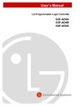
Automation Equipment
Programmable Logic Controller
XGT series incorporate the latest technological achievements in
Programmable Logic Controller, made possible by experience and
dedication to quality in design and manufacturing.
2
neXt Generation Technology
Contents
Overview
Overview
CPU &
System configuration
CPU module
Input/Output module
Precaution when setting digital I/O module
12
24
Network
Network configuration
FEnet/FDEnet system
Cnet system
Rnet system
Dnet system
Pnet system
Communication example
SMART I/O
General introduction
Analog input module
Analog output module
High-speed counter module
Positioning module
Motion control module
46
XG5000 programming
XG-PD programming
APM Software Package
68
Product list
Dimensions
86
Special
Software
Product
4
Programmable Logic Controller XGT Series
18
21
26
28
30
32
34
36
44
48
50
52
56
64
83
85
87
3
Overview
Overview
4
neXt Generation Technology
Overview
Programmable Logic Controller
neXt Generation Technology
XGT series is the next-generation solution with a new
concept providing advanced engineering environment
based on open network, fastest processing speed,
compact size and user-friendly software.
Programmable Logic Controller XGT Series
5
Overview
XGT series is the Industrial Workhorse that can support various
applications within the typical industrial plant.
Overview
Remote I/O
Base I/O
32,000
GM1
GM4C
Total I/O point
XGKCPUS
XGKCPUH
0.084
0.028
●Fast CPU processing speed: 28ns/step
(XGK-CPUH)
●Max. 32,768-point I/O control from
medium-to large-scale system
16,000
●Sufficient memory: Max. 64k step
GM2
●Integrated software package:
XG5000, XG-PD, APM Software Package
●Flexible system solution with open
network support
●Quick upload/download via USB port
●Expanded device capacity:
Index (Z), File register (R), Analog register (U)
8,192
6,142
4,096
GM3
3,072
2,048
GM4A
1,024
512
GM6/
K200S
K300S/
1000S
256
0.5
0.2
0.1
Processing speed (μs/step)
6
neXt Generation Technology
Overview
Size Innovation. . .
Compact
The smallest size
The smallest size (Dimensions 27×98×90)
achieves cost-efficiency and
various applications.
Item
Power Supply
CPU
8-slot Base
Size (W×H×D)
55×98×90
27×98×90
318×98×15
Programmable Logic Controller XGT Series
7
Overview
Speed Innovation. . .
Fast
Overview
The Fastest CPU Processing
MPU (NGP 1000) developed by LSIS
accomplishes the fastest CPU processing
speed. (0.028㎲/step)
High-speed Interface (Base)
Dedicated bus controller and High-speed
transmission algorithm achieve high performance
of internal interface.
8
Main Base
Expansion Base
20Mbyte/sec
5Mbyte/sec
neXt Generation Technology
Network Innovation. . .
Flexible
Overview
GLOFAView
System Integration of Open Network
XGT series support various communication solutions
ranging from field control to information level
with Fast Ethernet, Profibus-DP, DeviceNet,
MODBUS and even MECHATROLINK-II.
Profibus-DP
Item
Transmission speed
Transmission distance
Max. number of station
HS link
XG protocol
General Protocol
Service
P2P
XG5000 I/F
E-Mail
Configuration software
Number of installation
Fast Ethernet
FEnet
FDEnet
Cnet
Profibus-DP
DeviceNet
MECHATROLINK-II
10Mbps
100 / 10Mbps
300 ~ 115,200bps
Max. 12Mbps
Max. 500Kbps
100m (Node to Node, UTP/ STP)
2Km (Node to Node, Fiber Optic)
Max 500m
(422 / 485)
Max. 1.2Km
Max 500m
Max 50m
64 (HS link)
●
●
● (MODBUS)
●
●
●
32
126
64
16 (# of axis)
●
-
●
●
●
●
●
● (MODBUS)
●
●
-
-
-
-
-
XG-PD
XG-PD & SyCon
24 ( HS link Service: 12, P2P Service: 8)
No limit
Programmable Logic Controller XGT Series
9
Overview
Engineering & Programming Innovation. . .
Easy
Overview
Easy
Special Register
XGT series expand device memory and support advanced programming environment with
Index register (Z), File register (U), and Analog register (U).
R
File register
Analog register
As a non-volatile memory
type, data are secured even in
times of blackout
or CPU reset.
Assigning base, slot and memory buffer
of an analog module to device,
A/D conversion data can be
accessed without analog commands.
U
Index register
Z
Index register is used in the
sequence program for
array operation.
Example of Analog Register
Base No.
Slot No.
<KGLWIN>
Memory buffer
<XG5000>
Analog Operation without Programming
Special module setup and operation is achieved by just parameter setting without additional program.
X
X
Set up analog module
Program Modularization
modularization and
and Task
Task Operation
operation
Available to run multiful programs through modulization
of scan programs based on functions and author,
and to operate task programs triggered by
specific conditions.
10
Program type
Scan program Scan
Initialization task
Set up high-speed
counter module
Description
Executed in every scan
Executed only one time when power turns on
Time driven task Executed with a constant time interval specified
in parameter setting
Task program Internal task
Executed by internal condition
External interrupt
Executed by external interrupt input
task
Number
256-task
1
32
32
32
neXt Generation Technology
Software Innovation. . .
Intelligent
Overview
Integrated Programming & Engineering
XG5000 Software Package provides integrated engineering environment from basic programming to
different special module setting as well as diagnosis. This package consists of
XG5000 (PLC programming), XG-PD (Communication programming) and
APM Software Package (Positioning programming).
XG5000
Program Editing & Engineering Software
Windows-based Easy Operation
Multi-PLC Multi-Programming Support
Various Monitoring & Diagnosis Functions
XG-PD
Comm. & Network Parameter Setting
Protocol Editing / Network Diagnosis
Frame Monitoring / Protocol Analysis
APM S/W package
Positioning Parameter Setting
Data Editing in EXCEL
Various Monitoring & Diagnosis
Tracking Function
Intelligent
Programmable Logic Controller XGT Series
11
+
+
+
+
+
+
+
+
+
+
+
+
+
+
+
+
+
+
+
+
+
CPU
CPU &
System configuration
XGT series contain XGK-CPUS and XGK-CPUH for
customized solutions which support wide coverage
from small/middle- to large size-system control.
12
+
+
+
n e
+
+
+
+
+
+
+
+
+
+
G
T
X
t
e n e r a t i o n
e c h n o l o g y
CPU
Premium CPU for high-speed and large scale application
XGK-CPUH
Program capacity: 64K steps
I/O points: 6,144
I/O device point: 32,000 (Remote I/O)
Processing speed: 28ns/step
General sequence controller PLC CPU
XGK-CPUS
Program capacity: 32K steps
I/O points: 3,072
I/O device point: 32,000 (Remote I/O)
Processing speed: 84ns/step
Programmable Logic Controller XGT Series
13
CPU & System configuration / CPU module
System composition
CPU module
XGT-CPUS
MODE
RUN
STOP
ERROR
BAT
COM
USB cable
or
Battery
CPU module
XG5000
RS-232C
Type
I/O point
XGK-CPUH
XGK-CPUS
6,144
3,072
Item
Type
Description
USB cable
RS-232C cable
USB-301A
KIC-050A
USB downloading cable
RS-232C downloading cable
CPU
Power module
Free Voltage
AC
XGP-ACF2
XGP-AC23
XGP-DC42
220V
DC
Power module
(XGP-□□□□)
Main Base (XGB-M□□A)
Expansion cable
(XGC-E□□□)
Item
Type
Expansion
cable
XGC-E041
XGC-E061
XGC-E121
XGC-E301
XGC-E501
XGC-E102
XGC-E152
Expansion
terminator
Description
Expansion cable 0.4m
Expansion cable 0.6m
Expansion cable 1.2m
Expansion cable 3.0m
Expansion cable 5.0m
Expansion cable 10m
Expansion cable 15m
XGT-TERA Expansion terminator
16 points
32 points
64 points
AC110V
XGI-A12A
-
AC220V
XGI-A21A
-
8 points
16 points
32 points
Output module
64 points
Relay
Triac
Transistor
XGQ-RY1A
XGQ-RY2A
XGQ-RY2B
-
XGQ-SS2A
-
XGQ-TR2A
XGQ-TR2B
XGQ-TR4A
XGQ-TR4B
XGQ-TR8A
XGQ-TR8B
Output module
(XGQ-□□□□)
Special module
Expansion base (XGB-E□□A)
XGF-AV8A
XGF-AC8A
XGF-DV4A
XGF-DC4A
Analog output
XGF-DV8A *
XGF-DC8A *
XGF-HO2A
High-speed
counter
XGF-HD2A
XGF-PO3A
XGF-PO2A
XGF-PO1A
Positioning
XGF-PD3A
XGF-PD2A
XGF-PD1A
Analog input
Item
Main base
Expansion base
XGB-M04A
XGB-M06A
XGB-M08A
XGB-M12A
XGB-E04A
XGB-E06A
XGB-E08A
XGB-E12A
•XG5000 Cable (RS-232C)
Cnet (9Pin, Male)
DC24V
XGI-D21A
XGI-D22A
XGI-D22B
XGI-D24A
XGI-D24B
XGI-D28A
XGI-D28B
Input module
(XGI-□□□□)
Item
4 Slot
6 Slot
8 Slot
12 Slot
DC5V 3A
DC24V 0.6A
DC5V 6A
DC5V 8.5A
DC5V 6A
Input module
Item
8 points
XGP-ACF1
PC (9Pin, Female)
Motion control XGF-M16M
Special module
(XGF-□□□□)
Temperature
control
XGF-TC4S *
XGF-RD4A *
Voltage input type, 8Ch
Current input type, 8Ch
Voltage output type, 4Ch
Current output type, 4Ch
Voltage output type, 8Ch
Current output type, 8Ch
Pulse (OC) input type, 2Ch
Pulse (LD) input type, 2Ch
Pulse (OC) output type, 3 axes
Pulse (OC) output type, 2 axes
Pulse (OC) output type, 1 axis
Pulse (LD) output type, 3 axes
Pulse (LD) output type, 2 axes
Pulse (LD) output type, 1 axis
Motion dedicated net (M-II) type, 16 axes
Motion dedicated net (M-II) type, 8 axes
Temperature (TC) input, 4Ch, Insulation
Temperature (RTD) input, 4Ch
* OC: Open Collector
LD: Line Driver
Communication module
Cnet
FEnet
(Open Ethernet)
FDEnet
(Dedicated
Ethernet)
Communication
module
(XGL-□□□□)
14
Rnet
Dnet
Pnet
XGL-CH2A
XGL-C22A
XGL-C42A
XGL-EFMF
XGL-EFMT
XGL-EDSF
XGL-EDST
XGL-EDMF
XGL-EDMT
XGL-RMEA
XGL-DMEA
XGL-PMEA
RS-232C/RS-422
RS-232C, 2Ch
RS-422, 2Ch
Optical, Master, SC type
Electric, Master, RJ-45
Optical, Slave, SC type
Electric, Slave, RJ-45
Optical, Master, SC type
Electric, Master, RJ-45
Rnet, Master, TP
DeviceNet, Master, ODVA Standard
Profibus-DP, Master, DP Standard
neXt Generation Technology
Specifications
Item
Standard
Description
Ambient temperature
Storage temperature
Ambient humidity
Storage humidity
Frequency
10 ≤ f ‹ 57Hz
57 ≤ f ‹ 150Hz
Vibration resistance
Continuous vibration
Acceleration
4.9m/s2 {0.5G}
Pulse width
0.075mm
Pulse width
0.035mm
-
10 times
each
direction
(X, Y and Z)
·Peak acceleration: 147 m/s2 {15G}
·Duration: 11ms
Shock resistance
IEC 61131-2
IEC 61131-2
·Half-sine, 3 times each direction per each axis
Noise resistance
Operating Ambience
Altitude
Pollution degree
Cooling
Square wave impulse noise
±1,500Vp-p
Electrostatic discharge
±4KV
Radiated electromagnetic field noise
27~500MHz, 10V/m
Fast transient/ Burst noise
0.25KV
Free from corrosive gases and excessive dust
Up to 2,000m
Less than equal to 2
Air-cooling
LSIS Standard
IEC 61131-2. IEC 1000-1-2
IEC 61131-2. IEC 1000-1-3
IEC 61131-2. IEC 1000-1-4
* Pollution degree 2 is nonconductive pollution of the sort where occasionally a temporary conductivity caused by condensation must be expected.
Description
Item
Remarks
XGK-CPUS
XGK-CPUH
Operation method
Cyclic execution of stored program, Time-driven interrupt, Process-driven interrupt
I/O control method
Batch processing by scan synchronization (Refresh), Direct input/output by instructions
Ladder diagram, Instruction list
Program language
Number of
instructions
Basic
Application
Sequence instruction (㎲)
Processing
speed
Application instruction (㎲)
Floating instruction (㎲)
Program capacity
I/O points (available to install)
P
M
K
L
F
T
Data area
C
S
D
U
Z
File register
R
Program type
Total program
Initialization
Time-driven
External
Internal
Operation mode
Self-diagnosis
Programming port
Data retention at power failure
Max. expansion stage
Current consumption (mA)
Weight (Kg)
42
600
0.028㎲/step
0.084㎲/step
±: 0.602㎲ (S), 1.078㎲ (D)
×: 1.106㎲ (S), 2.384㎲ (D)
÷: 1.134㎲ (S), 2.66㎲ (D)
64K Steps
1536 (16-point I/O)
3072 (32-point I/O)
6144 (64-point I/O)
0.084㎲/step
0.252㎲/step
±: 0.602㎲ (S), 1.078㎲ (D)
×: 1.106㎲ (S), 2.384㎲ (D)
÷: 1.134㎲ (S), 2.66㎲ (D)
32K Steps
768 (16-point I/O)
1536 (32-point I/O)
3072 (64-point I/O)
P0000 ~ P2047F (32768 points)
M0000 ~ M2047F (32768 points)
K000 ~ K2047F (32768 points )
L000 ~ L11263F (32768 points )
F000 ~ F2047F (32768 points )
100ms: T0000 - T0999
10ms: T1000 - T1499
1ms: T1500 - T1999
0.1ms: T2000 - T2047
C0000 ~ C2047
S00.00 ~ S127.99
D0000 ~ D32767
D0000 ~ D19999
U0.0~U7F.31
128points
RAM: 2 blocks
Flash: 2M byte, 32 blocks
256
1 (_INT)
32
32
32
RUN, STOP, DEBUG
Execution, Delay, Memory error, I/O error, Battery error, Power error
RS-232C (1Ch), USB (1Ch)
Set “retain” at data declaration
4 (Main + Expansion), up to 15m
8 (Main + Expansion), up to 15m
960
960
0.12
0.12
RAM: 1 block
I/O relay
Auxiliary relay
Special relay
Link relay
Keep relay
Timer
(Adjustable)
Counter
Step controller
Register
Analog resister
Index register
1 block: R0 ~ R32767
MODBUS slave
Programmable Logic Controller XGT Series
15
CPU
Frequency
10 ≤ f ‹ 57Hz
57 ≤ f ‹ 150Hz
0 ~ 55 °C
-25 ~ +70 °C
5 ~ 95%RH (Non-condensing)
5 ~ 95%RH (Non-condensing)
Occasional vibration
Acceleration
9.8m/s2 {1G}
CPU & System configuration / CPU module
Main system composition
Item
XGK-CPUS
XGK-CPUH
3 stages
7 stages
48 modules
96 modules
Max. number of I/O point
3,072
6,144
Max. expansion distance
15m
15m
Max. expansion stage
Max. installation of module
•64 points are assigned to each slot of base regardless of installation of module.
•I/O numbers equivalent to 12 slots are assigned to a base.
•The starting number of base ‘0’ is P0000.
CPU
•Refer to the following figure regarding the I/O number assignment of 12 slots
Slot number:
5
P360
~
P39F
64 points
P320
~
P35F
64 points
P280
~
P31F
9 10 11
64 points
P240
~
P27F
8
64 points
P200
~
P23F
7
64 points
P160
~
P19F
6
64 points
P120
~
P15F
4
64 points
64 points
P80
~
P11F
3
64 points
P40
~
P7F
2
64 points
P0
~
P3F
1
64 points
Power CPU
0
64 points
Assignment of
I/O number
(Fixed)
P400
~
P43F
P440
~
P47F
•I/O point is assigned automatically according to the installed module.
•I/O parameter is used to install modules.
•The starting number of base ‘0’ is P0000.
•16 points are assigned automatically to the slot of special or communication module
Assignment of
I/O number
(Variable)
•Refer to the following figure regarding the I/O number assignment of 12 slots.
Slot number:
7
8
9 10 11
32 points
16 points
32 points
P110
~
P12F
P130
~
P16F
P170
~
P18F
P190
~
P19F
P200
~
P21F
P0220
~
P23F
0
1
2
3
4
5
32 points
64 points
P90
~
P10F
6
32 points
P80
~
P8F
5
32 points
P40
~
P7F
4
16 points
P20
~
P3F
3
64 points
P10
~
P1F
2
32 points
P00
~
P0F
1
16 points
The standard I/O number
assignment is 64 points.
(Fixed)
16 points
Power CPU
0
Expansion system composition
1. The following figure is the example of expansion
system with the fixed I/O point type of XGK-CPUH.
Main base
(Base number: 0)
Slot number:
Power CPU
2. The address of I/O point is adjustable by XG5000
parameter.
6
P0000 P0040 P0080 P0120 P0160 P0200 P0240
~
~
~
~
~
~
~
P003F P007F P011F P015F P019F P023F P027F
7
P0280
~
P031F
Expansion cable
Slot number:
Power
0
1
2
3
4
5
6
P0640 P0680 P0720 P0760 P0800 P0840 P0880
~
~
~
~
~
~
~
P067F P071F P075F P079F P083F P087F P091F
7
P0920
~
P095F
Switch for setting
base number: 1
Slot number:
Expansion base
Power
0
1
2
3
4
5
6
P1280 P1320 P1360 P1400 P1440 P1480 P1520
~
~
~
~
~
~
~
P131F P135F P139F P143F P147F P151F P155F
7
P1560
~
P159F
The lowest expansion base should be connected to the
upper stage with expansion terminator(XGF-TERA).
Slot number:
Power
16
0
P4480
~
P003F
1
2
3
4
5
6
P4520 P4560 P4600 P4640 P4680 P4720
~
~
~
~
~
~
P007F P011F P015F P019F P023F P475F
7
P4760
~
P479F
neXt Generation Technology
Remote I/O system application
Item
Network type (Master)
XGT base type remote I/O
Block type remote I/O (Smart I/O)
1
FDEnet
0
X
2
Profibus-DP
X
0
3
DeviceNet
X
0
4
Rnet
X
0
5
MODBUS (Cnet)
-
0
CPU
XGT base type remote I/O system
XGT base type remote I/O
system (Under development)
This system can be configured using
only FDEnet.
The master module of main base
should be connected to the
slave module (XGL-EDST) of remote
base. (XGL-EDST is under development)
FDEnet master
XGTACF1
XGKCPUH
Main base
XGLEDMT
Remote base (Same as main base)
FDEnet slave
XGTACF1
XGLEDST
Remark) Assignment of device memory and I/O number
•Through High-speed link parameter, users can assign device memory such as ‘P’, ‘M’, ‘K’, and ‘D’ to remote I/O.
Area ‘P’ should be set to use various functions such as initial reset, forced ON/OFF.
•Max. available point of I/O device memory (P) is 32,768 (P00000~P2042F)
•In case of constructing remote system, the assignment of I/O number is ‘fixed’ type (64 points, 4 words per slot)
•When setting up High-speed link parameter, the whole device memory of expansion base should be assigned at once regardless of distinction of I/O.
Ex) In case input module is set on 0, 2 slot and output module is set on 1, 4 slot in the remote 12 station,
- Reception: Starting address - P00000, Size - 20 words (0,1,2,3,4 slot)
- Transmission: Starting address - P00000, Size - 20 words (0,1,2,3,4 slot)
Block type remote I/O system
Block type remote I/O system consists
of Profibus-DP, DeviceNet, Rnet.
Users can use this I/O system regardless of
which series it is. Complying with the global
standard,
Profibus-DP and DeviceNet can
be connected to LS Smart-I/O
as well as other company’s
products.
FDEnet master
XGPACF1
XGKCPUH
Main base
XGL•••
Smart I/O
Smart I/O
Smart I/O
Programmable Logic Controller XGT Series
17
CPU & System configuration / I/O module
Features
•8, 16, 32, 64 points I/O module
•Operation monitoring by LED display
•Easy maintenance: Terminal block type, one-touch installation of module
CPU
Input module specifications
DC input
Input type
Type
XGI-D21A
Input point
XGI-D22A
8
XGI-D22B
XGI-D24B
16
DC24V
Rated input current
4mA
ON voltage/current
XGI-D28B
XGI-D28A
32
Rated input voltage
8
AC100~120V
Free voltage
8mA
17mA
5mA or less
10mA or less
AC30V or more /
AC60V or more /
1mA or less
2mA or less
1ms/5ms/10ms/20ms/70ms (set by CPU parameter) Initial value: 3ms
15mA or less
1ms/5ms/10ms/20ms/70ms (set by CPU parameter) Initial value: 3ms
On→Off
8 points/COM
16 points/COM
XGI-A21A
16
AC80V or more / AC130V or more /
DC11V or more / 1.7mA or less
Off→On
Common (COM)
XGI-A12A
64
19V or more / 3mA or less
OFF voltage/current
Response
AC input
XGI-D24A
25mA or less
32 points/COM
16 points/COM
8 points/COM
Photocoupler
Insulation method
Current consumption (mA)
20
30
50
60
30
20
Weight (Kg)
0.1
0.12
0.1
0.15
0.13
0.13
Output module specifications
Relay
Input type
Type
XGQ-RY1A
Rated load voltage
Rated output
current
Response time
XGQ-RY2B
16
8
Output point
Transistor
XGQ-RY2A
XGQ-TR2B
16
DC12/24V, AC110/220V
XGQ-TR4A
Triac
XGQ-TR4B
XGQ-TR8A
32
64
2A
0.5A
0.1A
5A
4A
2A
Off→On
10ms or less
1ms or less
On→Off
12ms or less
1ms or less
1 point/COM
260
Weight (Kg)
0.13
Surge killer
External power supply
4A
1ms or less
+1ms or less
16 points/COM
Photocoupler
500
-
0.6A
32 points/COM
16 points/COM
0.17
16
0.5cycle
Relay
Current consumption (mA)
XGQ-SS2A
AC110/220V
1 point
Insulation method
XGQ-TR8B
DC12/24V
Common
Common (COM)
0.19
Varistor
-
Note) B1, B2 of 32, 62 points terminal (connector) are shorted inside of the product.
18
XGQ-TR2A
70
130
230
0.11
0.1
0.15
300
0.2
Zener diode
Varistor
DC
-
neXt Generation Technology
Wiring diagram for input modules
XGI-D21A
XGI-D22A
XGI-D22B
XGI-D24A
CPU
XGI-D24B
XGI-A12A
XGI-D28A
XGI-D28B
XGI-A21A
Programmable Logic Controller XGT Series
19
CPU & System configuration / I/O module
Wiring diagram for output modules
XGQ-RY2A/B
XGQ-TR4A
XGQ-TR4B
XGQ-TR2A
XGQ-TR2B
CPU
XGQ-RY1A
XGQ-TR8B
20
XGQ-TR8A
XGQ-SS2A
neXt Generation Technology
CPU & System configuration / I/O module
Precaution during installation of I/O module
•XGT has 2 kinds of digital input type: Current sink input, Current
•The following graph presents the relay lifespan of relay output module.
source input. For DC input module has different wiring depending on
the input type, digital input type should be selected with consideration
about connected input device.
It shows the maximum lifespan of relay which is used in the relay
output.
•Max. number of simultaneous input point differs according to the
module type. Therefore, review specification of input module before its
application.
demanded. But only one interrupt module can be installed per CPU
module.
•If switching frequency is high or inductive switching load is used, the
lifespan of relay output module will be reduced. Therefore, it is
recommended to use transistor output module or triac output module.
No. of
switching 100
(x 10,000)
CPU
•Use an interrupt module when a response of high-speed input is
50
30
20
10
AC 125V Resistive load
DC 30V Resistive load
AC 250V Resistive load
•When driving an inductive load with output module, set the maximum
switching frequency as‘ON’for 1 second and‘OFF’for 1 second.
•When using counter or timer with DC/DC converter, it is possible to
0.5
have inrush current which cause a break down. Therefore to reduce
an effect of inrush current, connect resistor or inductor to load or use
the module whose max. load current is high.
Resistor
Load
1
2 3
5
10
100
Switching current
•Compressed terminal attaching sleeve cannot be mounted to XGT
terminal block. The following picture shows appropriate compressed
terminals for terminal block.
Output
moduls
Inductor
Load
6.0mm
or less
Output
moduls
•Fuse of output module is not exchangeable to prevent a damage of
6.0mm
or less
external wiring when output module has a short-circuit.
•The number of simultaneous‘ON’points varies depending on input
voltage, ambient temperature. Refer to the specification of input
module.
•Use 0.3~0.75mm2 twisted pair, below 2.8mm thickness cable for
connecting to terminal block.
•Be careful when choosing and using the cable since the permissible
current differs according to the insulation thickness.
•Joint torque of fixed screw and terminal block screw of the module
needs to be within the range in the following table.
Joint
Joint torque range
I/O module terminal block screw (M3)
42~58 N·cm
I/O module terminal block fixed screw (M3)
68~89 N·cm
•Thermal protector is built in transistor module. Thermal protector is a
function that protects PLC from an overload and overheating.
Programmable Logic Controller XGT Series
21
Network
Network
Along with Ethernet, Profibus-DP, and DeviceNet,
XGT series provide the maximum in control
integration and communication flexibility.
22
n e
G
T
X
t
e n e r a t i o n
e c h n o l o g y
XGT FEnet / FDEnet (Fast Ethernet)
XGT Cnet
•RS-232C/485/422 communication
•Long-distance communication via modem connection
•Various connection to MMI S/W
(XGT, MODBUS RTU, MODBUS ASCII)
•User-defined communication support
•Convenient P2P master (XGT, MODBUS)
XGT Rnet
•Economical network
•Communication speed: 1Mbps
•Communication distance: Max. 750m
•Available to use max. 6 repeaters (Support up to 5.25Km)
•Network management using Auto-scan (Slave module information)
XGT Dnet (DeviceNet)
•Connectable to other PLCs and control device
•Compliance of the ODVA standard
•Flexible communication speed setting: 125/250/500Kbps
•Multi-drop and T branch connection
•Communication distance: Max. 500m
•Convenient parameter setting through SyCon/HS link parameter
XGT Pnet (Profibus-DP)
•Low cost network appropriate to field level
•Proper to communicate among a master automation device and
distributed slave I/O devices
•Fast slave communication omitting application layer
•Long communication distance: Max. 1200m
•Convenient parameter setting through SyCon/HS link parameter
Programmable Logic Controller XGT Series
23
Network
•10/100Mbps High-speed Ethernet for industrial use
•10/100Base-TX, 100Base-FX (Optical)
•Open Ethernet (FEnet) and LSIS dedicated Ethernet (FDEnet)
•High reliability and performance with 32-bit processor
•Various connection to MMI S/W (XGT, MODBUS/TCP)
Network / General introduction
Features
XGT FEnet / FDEnet (Fast Ethernet)
•10/100Mbps High-speed Ethernet for industrial-use
•10/100Base-TX, 100Base-FX (Optical)
•Open (Information level) Ethernet and
LSIS dedicated (Between LS PLCs) Ethernet: FEnet and FDEnet
•High reliability and performance with 32-bit processor
•Various connection to MMI S/W (XGT, MODBUS)
XGT Cnet
•RS-232C/485/422 communication
•Long-distance communication via modem connection
dedicated line modem connection
•Various connection to MMI S/W
Network
(XGT, MODBUS RTU, MODBUS ASCII)
•User-defined communication support
•Convenient P2P master (XGT, MODBUS)
XGT Rnet
•Economical and various network
•High-speed communication: 1Mbps
•Long communication distance: Max. 750m
•Available to use max. 6 repeaters (Up to 5.25Km)
•Network management using Auto-scan
(Slave module information)
PC HMI
FEnet, FDEnet
IFOS
XGT
XGT
FEnet (Fast Ethernet)
Redundant Ethernet
MK300S
PMU 830
IGS200
GM4
GMR
Ethernet
Serial / Ethernet
Temperature controller
GMPC-V
i-Net
24
neXt Generation Technology
XGT Dnet (DeviceNet)
•Connectable to other PLCs and control device
•Compliance of the ODVA standard
•Flexible communication speed setting: 125/250/500Kbps
•Multi-drop and T branch connection
•Long communication distance: Max. 500m
XGT Pnet (Profibus-DP)
•Low cost network appropriate to field level
•Proper to communicate among a master automation device
and distributed slave I/O devices
Network
•Fast slave communication omitting application layer
•Long communication distance: Max. 1200m
•Communication using High-speed link parameter
No. of network module available
Item
XGK-CPUH
XGK-CPUS
Total network module
24
24
High-speed link module
12
12
P2P service
8
8
WEB
IFOS
Wireless LAN
GM4
XGT
Dedicated Ethernet (FDEnet)
XGT
XGT
GM4
MECHATROLINK Ⅱ
Rnet (LS Dedicated )
Smart I/O
PMU830
Profibus-DP
Smart I/O
K120S
XGT-Panel
Cnet
DeviceNet
Smart I/O
Other PLC
Other INV
Programmable Logic Controller XGT Series
25
XGT FEnet / FDEnet system (Fast Ethernet)
Features
•10/100Mbps High-speed Ethernet for industrial use (IEEE802.3)
•Expanded High-speed link block (128 blocks)
•10/100Base-TX, 100Base-FX (Optical)
•Open (Information level) Ethernet and LSIS dedicated
(Between LS PLCs) Ethernet: FEnet and FDEnet
•High reliability and performance with 32-bit processor
•Remote programming, monitoring and PLC mode control by XG5000
•E-Mail transmission support
•Easy programming (MODBUS/TCP) with other brands’
built-in protocol (Device Driver)
•Providing information of network system by Auto-scan
•Providing XGT/MODBUS communication drivers
(MMI/PC communication)
Network
•Easy setting of network configuration and various
diagnosis/monitoring: XG-PD
•User protocol editing and command application by P2P service
(Connectable to other brands)
•Module checking function (PING)
•Providing information of services
(High-speed link, P2P, dedicated service, media condition)
PC HMI
Bridge or
Router
FEnet
XGK-CPUH
XGL-EFMT
XGL-EFMF
XGK-CPUS
XGL-EFMT
XGL-EFMF
XGL-EDMT
XGL-EDMF
GM4
G4L-EUFB
XGL-EDMT
XGL-EDMF
G4L-EUTC
G4L-EU5C
Public
network
Internet
FDEnet
XGL-EDST
XGL-EDSF
GM4
G4L-EUTC
G4L-EUFC
G4L-EU5C
XGK-CPUH/S
XGL-EDMT
XGL-EDMF
Bridge or
Router
G4L-ERTC
G4L-ERFC
G4L-ER5C
FEnet
XGK-CPUH/S
XGL-EFMT
XGL-EFMF
26
G4L-EUTB
G4L-EU5B
XGK-CPUS
XGL-EFMT
XGL-EFMF
GM4
G4L-EUFB
G4L-EUTB
G4L-EU5B
G4L-EUFC
neXt Generation Technology
Specifications
FDnet
Item
Communication spec.
XGL-EFMT
XGL-EFMF
10/100 BASE-TX
100 BASE-FX, Fiber Optic
Protocol
TCP/IP, UDP/IP
With LS PLCs
Service
High-speed link, P2P service
P2P service
With other devices
Dedicated protocol service, XG5000 service, E-Mail service
Application
200 words/block (Max. 128 blocks)
HS link sending/receiving data
16 channels
No. of channel connectable to upper stage
Communication with PC (HMI) and external devices, High-speed communication among LSIS PLCs
General use
Media
UTP/STP Category 5
62.5/125㎛, Multi-mode, SC connector
Current consumption (mA)
410
630
Weight (Kg)
0.11
0.15
Item
Communication spec.
XGL-EDMT
XGL-EDMF
10/100 BASE-TX
100 BASE-FX, Fiber Optic
Dedicated protocol
Protocol
High-speed link, P2P service
With LS PLCs
Service
Network
FDEnet
-
With other devices
XG5000 service
Application
200 words /block
Sending/receiving data
64 stations
No. of connection stations
High-speed link communication among LSIS PLCs
General use
UTP/STP Category 5
Media
62.5/125㎛, multi-mode, SC connector
Current consumption (mA)
410
630
Weight (Kg)
0.11
0.15
PC HMI
FEnet
GM4, K300S
G4L-EUFB
GM6, K200S
G6L-EUTB
G6L-EUFB
G4L-EUTB
G4L-EU5B
Other PLC
G6L-EUTC
G6L-EUFC
G4L-EUTC G4L-EUFC
G4L-EU5C
Ethernet I/F
FDEnet
GM6, K200S
G6L-ERTC
G6L-ERFC
GM6, K200S
G6L-EUTC
G6L-EUFC
G4L-ERTC
G4L-ERFC
G4L-ER5C
GM4, K300S
G4L-EUTC
G4L-EUFC
G4L-EU5C
FEnet
GM4, K300S
G4L-EUFB
G4L-EUTB
G4L-EU5B
GM6, K200S
G6L-EUTB
G6L-EUFB
Other PLC
Ethernet I/F
Programmable Logic Controller XGT Series
27
Network / Cnet system
Features
•Various protocol editing and communication parameter setting: XG-PD
•Long-distance communication via modem connection
•Dedicated protocol for multi-drop configuration connectable up to 32 units
•RS-232C/422 communication port
•Flexible communication speed setting (300~115,200bps)
•Supporting full duplex and half duplex communication
•Max. 12 modules available in one CPU
•P2P service: User-defined communication and XGT/MODBUS master
•Various connection to MMI S/W (XGT, MODBUS RTU, MODBUS ASCII)
•Various diagnosis functions using XG-PD
Network
(I/O, link status, service status), monitoring sending/receiving
frame simultaneously and displaying frame’s result
•Communication service information (Dedicated service, P2P service)
•Supporting simultaneously dedicated service in remote connection
•Communication without additional setting when
replacing communication module
Various independent operation mode
•Operation mode
•Dedicated protocol mode (Simultaneous support)
•Program upload/download by XG5000 protocol (RS-232C)
Communication using LSIS dedicated protocol
•User-defined communication of P2P mode and
XGT/MODBUS master
Communication via RS-232C/422
XGK-CPUH/S
XGL-C22A
XGL-C42A
XGL-CH2A
RS-232C/422
1: N and N: M connection (LSIS and other)
Other PLC
Other PLC
RS-232C interface
Long distance available
RS-232C interface
XGK-CPUH/S
XGL-C22A
XGL-CH2A
XGK-CPUH/S
XGL-C42A
XGL-CH2A
28
RS-232C interface
XGK-CPUH/S
XGL-C22A
XGL-CH2A
GM4, K300S
RS-422/485
GM4, K300S
GM6, K200S
neXt Generation Technology
Specifications
Specifications
Item
Interface
XGL-C22A
XGL-C42A
XGL-CH2A
RS-232C, 2 channels
RS-422, 2 channels
RS-232C/RS-422, 1 channel
Remote communication with external devices via modem connection. Available for only RS-232C port.
Modem connection
Dedicated mode
Communication
mode
XG5000 mode
Operation
mode
Server (Slave)
Data type
1: 1 or 1: N communication using LSIS dedicated protocol
Program upload/download and remote control
Communication by protocol using XG-PD (Interface with other PLCs),
P2P mode
XGT, MODBUS RTU/ASCII master communication
Remote connection simultaneously using XGT/MODBUS Server, user-defined
Master
XGT, MODBUS RTU/ASCII master, user-defined
Start Bit
1
Data Bit
7 or 8
1 or 2
Stop Bit
Even/Odd/None
Parity
Network
Basic parameter setting with XG-PD
Setting
Synchronization
Asynchronous
Transmission speed (bps)
Selectable among 300/600/1,200/2,400/4,800/9,600/19,200/38,400/57,600/115,200 bps
Station number setting
Up to 32 stations from 0 to 31 with XG-PD
Transmission distance
RS-232C: Max. 15m (Extendible by using modem), RS-422/485: Max. 500m
Modem communication
Available
Not available
Network configuration
Available via RS-232C
RS-232C 1: 1, RS-422 1: 1, 1: N, N: M
Diagnosis function
Available through LED and XG-PD diagnosis service
12
Max. number of installation
Current consumption (mA)
310
300
310
Weight (Kg)
0.12
0.12
0.12
MODBUS
SMART I/O
RS-232C interface
Long distance available
GSL-D22A/D24A
LS Inverter
XGK-CPUH/S
XGL-C22A
XGL-CH2A
GLOFA/MASTER-K
GSL-TR2A/TR4A
Other PLC
GSL-RY2A
XGK-CPUH/S
XGL-C42A
XGL-CH2A
GSL-DT4A
RS-422/485 interface
(MODBUS)
Cnet cable connection
Cnet (9Pin, Male)
Cnet (9Pin, Male)
Cnet (9Pin, Male)
PC (9Pin, Female)
Programmable Logic Controller XGT Series
29
Network / Rnet system
Features
•Economical network
•Communication speed: 1Mbps
•Communication distance: Max. 750m
•Available to use max. 6 repeaters (Up to 5.25Km)
•Network management using Auto-scan (Slave module information)
•Multi-drop network with smart I/O
•Network diagnosis and monitoring by XG-PD
•Max. 64 stations of slave modules controlled by one master module
Network
System configuration
XGK-CPUH/S
XGL-RMEA
XG5000
Loader I/F Module
GOL-GWRA
Repeater
GOL-FREB
GOL-FREC
Electric/optical
GOL-FOEA
SMART I/O Rnet
GRL-D22A
GRL-TR2A
GRL-TR4A
PMU Series
PMO-730R
PMO-530R
PMO-330R
GM4, K300S
G4L-RUEA
GM4, K300S
G4L-RUEA
GM6, K200S
G6L-RUEA
GRL-RY2A
GRL-DT4A
30
neXt Generation Technology
Specifications
Item
Specifications (XGL-RMEA)
1Mbps
Transmission speed
Manchester Biphase-L
Encoding
Max. 750m
Transmission distance (Per segment)
Max. 750m * (6 repeater +1) = 5.25Km
Transmission distance (When using repeater)
Twisted pair shield cable
Transmission cable
Max. number of connection stations
Master + Slave = 64 stations (with repeater), 1 segment=32 stations (with master)
Max. size of protocol
256 bytes
Medium access method
Circulated Token Passing
Frame error check
CRC 16 check
Max. number of installation
12
Installation position
Main base or expansion base
Current consumption (mA)
410
Weight (Kg)
0.12
Network
SMART I/O
•Reduction of wiring and real-time control of distributed I/O
•Various I/O module (16/32 points)
Repeater specifications
Item
Specifications
G0L-FREB: AC110V ~ AC220V, G0L-FREC: DC 24V
Type
Communication speed
1Mbps
Transmission method
Twisted pair shield cable
Transmission distance
Max. 750m per repeater
Max. 6 repeaters
Max. number of installation between stations
5.25Km (when 6 repeaters are installed)
Max. distance between stations
Error data transmission
Faulty data reception
CRC 16 check
Frame error check
Network cable and peripheral devices
Item
Twisted pair electric cable
RF terminator
Specifications
Remarks
LIREV-AMESB, 2×1mm, 18AWG
LS cable
110Ω, 1/2 Watt
-
Programmable Logic Controller XGT Series
31
Network / Dnet system
Features
•DeviceNet protocol
•Direct control of various I/O devices via Dnet system
•Max. 63 slave modules controlled by one master module
•Flexibility in network configuration: Multi-drop and T branch connection
•Connectable to other master module and various slave modules
•Providing ‘Auto Network Scan’ function and various information with configuration tool (SyCon)
•Communication using High-speed link parameter
•Connectable to various slave I/O including other module
Network
(Common I/O, Actuator, Switch, Optical switch, Valve, Inverter,
A/D module, Position controller etc..)
•Automatic monitoring of slave modules in the network:
Auto-scan (XG-PD)
•Easy expansion for abundant I/O & line:
1 CPU module affordable up to 12 master modules
•Network setting by SyCon/XG-PD
(Parameter setting, diagnosis and monitoring)
System configuration with LSIS products
SyCon, XG-PD
XGK-CPUH/S
XGL-DMEA
(Master)
SMART I/O Dnet
GDL-D22A/C
GDL-D22A/C
GDL-TR2A/A1/B/C/C1
GDL-TR4A/A1/B/C/C1
GDL-RY2A/C
LS Inverter
GDL-DT4A/A1/B/C/C1
32
neXt Generation Technology
Specifications
Item
Specifications (XGL-DMEA)
Master
Module type
Trans. speed
Max. network length
Max. drop cable
Length of all drop cable
Transmission
500kbps
100m
6m
39m
distance and speed
250kbps
250m
6m
78m
125kbps
500m
6m
156m
Max. number of
64 stations (Master 1 + Slave 63)
connection stations
Max. number of node
Max. 64 MAC ID (Node address)
Communication method
Diagnosis function
Bit Strobe, Poll, COS, Cyclic
Duplicated station check Abnormal station detection/CRC error check/Scan List/Operation display (LED)
Cable
Dnet dedicated cable: 5 (Signal: 2, power: 2, shield: 1)
Max. number of installation
12
SyCon
Configuration port
RS-232C Configuration Port
Current consumption (mA)
440
Weight (Kg)
0.11
Network
Configuration tool
System configuration with other products
SyCon, XG-PD
XGK-CPUH/S
XGL-DMEA
(Master)
A.B, OMRON,
FUJI
A.B
Other inverter
(DeviceNet driver)
DeviceNet
Driver
OMRON
Other I/O device
Programmable Logic Controller XGT Series
33
Network / Pnet system
Features
•Profibus-DP protocol
•Low cost network appropriate to field level
•Proper to communicate among a master automation device and distributed slave I/O devices.
•Fast slave communication without application layer
•Transmission speed: 9.6Kbps ~ 12Mbps
•Transmission distance: Max. 1,200m
•Max. 126 slave stations available (32 stations per segment)
•Network setting using SyCon/XG-PD
(Parameter setting, diagnosis and monitoring)
•Available to use 7Kbytes I/O data of master station
•Automatic monitoring of slave modules in the network:
Auto-scan (XG-PD)
Network
•Supporting multi-master
•Providing ‘Auto Config’ and various information
with configuration tool (SyCon)
System configuration with LSIS products
SyCon, XG-PD
XGK-CPUH/S
XGL-PMEA
GM4, K200S
G4L-PUEA
G4L-PUEB
GM4, K200S
G4L-PUEA
G4L-PUEB
GM6, K200S
G6L-PUEA
G6L-PUEB
SMART I/O Pnet
GPL-D22A/C
GPL-TR2A/A1/B/C/C1
GM7, K80S
G7L-PBEA
GPL-RY2A/C
LS Inverter
GPL-DT4A/A1/B/C/C1
34
neXt Generation Technology
Specifications
Item
Specifications (XGL-PMEA)
Module type
Master
Network type
Profibus-DP
Standard
EN50170/DIN19245
Interface
RS-485 (Electric)
Media access
Token Passing & Poll
Topology
Bus
Modulation
NRZ
Cable
Shield Twisted Pair Cable
1,000m
9.6K~187Kbps
Transmission distance
400m
and speed
200m
1.5Mbps
100m
3M~12Mbps
500Kbps
Max. number of slave per network
126
Network
Max. number of slave per segment
32
Max. I/O data
Input: 3584byte, Output: 3584byte
Max. number of communication points
7Kbytes
Communication parameter setting
XG-PD, SyCon
Max. number of installation
12
Configuration Tool
SyCon
Configuration Port
RS-232C Configuration Port
Current consumption (mA)
550
Weight (Kg)
0.11
System configuration with other products
SyCon, XG-PD
XGK-CPUH/S
XGL-PMEA
GM4, K200S
G4L-PUEA
G4L-PUEB
GM4, K200S
G4L-PUEA
G4L-PUEB
GM6, K200S
G6L-PUEA
G6L-PUEB
A.B
Other inverter
A.B, Siemens
Profibus
Device Driver
Siemens
Other Profibus I/O
Programmable Logic Controller XGT Series
35
Network / Communication example (Cnet)
Communication
among PLCs
This is a system configuration communicating between XGT PLCs by serial communication.
In this case, PLC 1 is the master (Client) and other PLC should be slaves (Server).
It is called Master/Slave communication. Master PLC is defined by comm. basic parameter and P2P setting.
And slave PLC is defined by basic parameter and driver setting.
Data memory
Configuration
PLC1 reads present value, C0000 of PLC2’s
up-counter and then saves it in M0200 of PLC1.
PLC station
PLC memory
PLC 1
M0100
PLC 2
C0000
RS-232C/422/485
115,200bps
Setting Item
1. XG-PD parameter setting,
2. XG5000 programming
1. XG-PD parameter setting,
2. XG5000 programming
PLC2 (Slave)
PLC1 (Master)
XG-PD setting
Network
PLC 1 setting (Master)
Communication basic parameter setting
Setting up station number, communication
speed, etc. And setting up the operation
mode as P2P
P2P channel setting
Setting up channel 01 as [XGT client]
Enable Link
Enabling P2P for communication start
Parameter writing
Downloading parameters to PLC after
online connection
P2P setting
Setting up P2P block (READ)
Communication data setting
Setting up Read area, Save area, etc.
PLC 2 setting (Slave)
Parameter writing
Downloading parameters to PLC after
online connection
Communication parameter setting
Setting up station number and channel 01
mode as 1 and XGT server
* For basic parameter setting and SyCon setting/change, reset the module (Online reset).
XG5000 programming
PLC station 2 setting
Make up-counter program using
CTU command
PLC station 1 setting
Check out the counter value of
M0100 is transmitted.
36
neXt Generation Technology
HMI
communication
configuration
This is a system configuration to monitor and control PLC (XGT) by PMU (HMI). In this case,
PLC is the slave (Server) and PMU should be the master (Client).
PLC is defined by comm. basic parameter and driver setting.
Configuration
Data memory
Making On/Off touch tag for controlling M0001 of XGT
PLC memory
Setting item
PMU
1. XG-PD parameter setting
M000D1
Using touch tag
2. XG5000 programming
RS-232C/422/485
115,200bps
Network
XG-PD setting
Basic communication parameter setting
Setting up station number, communication
speed, etc And setting up the operation
mode as XGT server
Parameter writing
Downloading parameters to PLC after
online connection
PMU setting
Setting up communication setting (speed,
data, stop, parity, etc) same as XGT
* For basic parameter setting and SyCon setting/change, reset the module (Online reset).
XG5000 programming
Create program that
P00010 is on right
after M00001
is on.
Programmable Logic Controller XGT Series
37
Network / Communication example (FEnet)
HMI
communication
configuration
This is a data communication system configuration among XGT PLCs via Ethernet network.
In this case, communication is possible by HS link among PLCs.
It just needs basic parameter setting and HS link item setting.
Configuration
Data memory
Read the up-counter value C0000 of PLC1
and monitor it in GLOFAview.
PLC memory
Setting item
GLOFAView
1. XG-PD parameter setting
C0000
Using analog tag
2. XG5000 programming
GLOFAView PC IP: 100.100.100.1
Fast Ethernet (100Mbps)
Network
PLC1 IP: 100.100.100.2
PLC2 IP: 100.100.100.3
PLC3 IP: 100.100.100.4
PLC4 IP: 100.100.100.5
XG-PD setting
PLC 1 setting (Master)
Basic communication parameter setting
Specifying IP address and Subnet mask of
PLC as above
Ping Test
Starting diagnosis after inputting IP
address of PLC
System Diagnosis
Selecting Ping Test
* For basic parameter setting and SyCon setting/change, reset the module (Online reset).
XG5000 programming
Make the up-counter program
using CTU command.
Check out if the counter
value of CTU value is transmitted.
38
Parameter writing
Downloading parameters to PLC after
online connection
Communication test
Checking online and system diagnosis
neXt Generation Technology
High-speed link
communication
This is a configuration for XGT to communicate each other via Ethernet.
It just needs communication basic parameter setting and High-speed link item setting.
Data memory
Configuration
Read present value C0000 of PLC1
and transmit it to M0000 of PLC2.
PLC station
Fast Ethernet (100Mbps)
PLC2 IP: 100.100.100.3
2
PLC3 IP: 100.100.100.4
3
PLC 1
C0000
PLC 2
M0100
Setting Item
1. XG-PD parameter setting,
2. XG5000 programming
1. XG-PD parameter setting,
2. XG5000 programming
PLC4 IP: 100.100.100.5
4
Network
PLC1 IP: 100.100.100.2
High-speed link station
number 1
PLC memory
XG-PD setting
PLC station 1
setting
Parameter writing
Downloading parameters to PLC
after online connection
Basic communication parameter setting
Specifying HS link station, IP address and
Subnet mask of PLC as above
Communication data setting
Setting up communication data in HS link
item as above
Enable Link
Enabling link for communication
start
PLC station 2
setting
Parameter writing
Downloading parameters to PLC
after online connection
Basic communication parameter setting
Specifying HS link station, IP address and
Subnet mask of PLC as above
Communication data setting
Setting up communication data in HS link
item as above
Enable Link
Enabling link for communication
start
* For basic parameter setting and SyCon setting/change, reset the module (Online reset).
XG5000 programming
PLC1 setting
Make the up-counter
program using CTU
command
PLC2 setting
Check out if the counter
value of M0100 is
transmitted.
Programmable Logic Controller XGT Series
39
Network / Communication example (Rnet)
LSIS developed communication method is Rnet which is ‘Distributed Control System’ using Smart I/O.
In this case, PLC is the master and the other Smart I/O are slaves.
It just needs basic parameter setting for communication and High-speed link setting.
Remote I/O
configuration
Configuration
PLC controls each Smart
I/O (16-point).
PLC (Master)
Rnet 1Mbps, 750m
S I/O #1 (Input)
S I/O #2 (Input)
S I/O #3 (Input)
S I/O #4 (Output)
S I/O #5 (Output)
Data memory
Network
Smart I/O #
Smart I/O address
PLC address
1
P0000
P0010 (P00100~P0010F)
Setting item
2
P0000
P0011 (P00110~P0011F)
3
P0000
P0012 (P00120~P0012F)
4
P0000
P0013 (P00130~P0013F)
5
P0000
P0014 (P00140~P0014F)
1. XG-PD parameter setting,
2. XG5000 programming
XG-PD setting
Communication data setting
Setting up type name, station
number, address of each station’s
Smart I/O in HS link item as
following example.
HS link registration completed
Parameter writing
Downloading parameters to PLC
after online connection
* For basic parameter setting and SyCon setting/change, reset the module (Online reset).
XG5000 programming
Write a program using I/O
address of Smart I/O.
40
Enable Link
Enabling link for communication
start
neXt Generation Technology
Network / Communication example (Pnet)
High-speed link
communication
among PLCs
XGT can create‘Distributed Control System’with Smart I/O, Inverter, pneumatic device via Profibus-DP.
In this case, PLC is the master and the other devices such as Smart I/O are slaves.
It just needs SyCon, basic parameter and High-speed link setting.
Configuration
PLC controls each Smart
I/O (16-point).
PLC (Master)
Profibus-DP 12Mbps
S I/O #15 (Input)
S I/O #20 (Output)
S I/O #21 (Output)
Other
LS Inverter
Network
Data memory
Smart I/O #
Smart I/O address
PLC address
15
P0000
P0010 (P00100~P0010F)
20
P0000
P0011 (P00110~P0011F)
21
P0000
P0012 (P00120~P0012F)
Setting item
1. SyCon setting
2. XG-PD parameter setting,
3. XG5000 programming
XG-PD setting
SyCon setting
For detailed setting instruction, refer to
page 43 (SyCon setting)
HS link setting
Uploading SyCon and setting up each
Smart I/O station as following example
Parameter writing
Downloading parameters to PLC after
online connection
Enable Link
Enabling link for communication
start
* For basic parameter setting and SyCon setting/change, reset the module (Online reset).
XG5000 programming
Write a program using I/O
address of Smart I/O Pnet
Programmable Logic Controller XGT Series
41
Network / Communication example (Dnet)
High-speed link
communication
between PLCs
XGT can create ‘Distributed Control System’ with Smart I/O, Inverter, pneumatic device via Dnet.
In this case, PLC is the master and the other devices such as Smart I/O are Slaves.
It just needs SyCon, basic parameter and High-speed link setting.
Configuration
PLC controls each
Smart I/O (16 points).
PLC (Master)
DeviceNet 500kbps
S I/O #19 (Input)
S I/O #20 (Output)
S I/O #21 (Output)
Other
LS Inverter
Network
Data memory
Smart I/O #
Smart I/O address
PLC address
19
P0000
P0010 (P00100~P0010F)
20
P0000
P0011 (P00110~P0011F)
21
P0001
P0012 (P00120~P0012F)
XG-PD setting
SyCon setting
For detailed setting instruction, refer to
page 43 (SyCon setting)
HS link setting
Uploading SyCon and setting up each
Smart I/O station as following example
Parameter writing
Downloading parameters to PLC after online
connection
Enable Link
Enabling link for communication
start
* For basic parameter setting and SyCon setting/change, reset the module (Online reset).
XG5000 programming
Write a program
using I/O
address of
Smart I/O Dnet.
42
Setting item
1. SyCon setting
2. XG-PD parameter setting,
3. XG5000 programming
neXt Generation Technology
Network / Communication example (SyCon setting for Pnet, Dnet)
SyCon is the dedicated software that help user set up the communication environment for
Profibus-DP and DeviceNet more easily and conveniently.
Example of application
New file
Select fieldbus that is used.
Basic communication parameter setting
Select [Master] in Insert menu.
Master module setting
Select [COM-C-DNM] for DeviceNet.
Select [COM-C-DPM] for Profibus-DP.
Network
Bus parameter setting
Set up communication speed of master
module.
Master module setting
After clicking the port button, check
the right check-box.
Automatic network scan of connected Smart I/O
Perform automatic network scan after station number
setting and wiring with remote device such as Smart I/O.
At this time, all remote devices should be in normal connection (Power-On, etc).
After network scan is completed, press [Automatic Configuration] button and [OK] button.
Network checking
Check normal network (remote) condition.
Parameter download
Disconnect
Disconnect the port in Device Assignment.
Programmable Logic Controller XGT Series
43
Network / Smart I/O
Features
•Wiring reduction and real time control of distributed I/O
•Supporting Rnet, DeviceNet, Profibus-DP, MODBUS (RS-422/485)
•Various I/O (DC/TR/Relay) modules with the unit of 16/32 points
Specifications
Input
Item
No. of point
Output
DC (Sink/Source)
Transistor (Sink)
16
16
32
Rated input (Load voltage)
32
DC 24V
Input current (Load current)
DC 24V
7mA
Mixed module
DC (Sink/Source) Transistor (Sink)
Relay
16
16
16
DC 24V/AC 110V/220V
DC 24V
DC 24V
Network
2A/5A
7mA
0.1A/2A, 0.5A/3A
Response
Off → On
3ms or less
3ms or less
3ms or less
3ms or less
3ms or less
time
On → Off
3ms or less
3ms or less
3ms or less
3ms or less
3ms or less
16 points/COM
16 points/COM
16 points/COM
16 points/COM
16 points/COM
Common
Current consumption
Rnet
Network
0.1A/2A, 0.5A/3A
200mA
300mA
280mA
380mA
550mA
350mA
GRL-D22A
GRL-D24A
GRL-TR2A
GRL-TR4A
GRL-RY2A
GRL-DT4A
Profibus-DP
GPL-D22A● GPL-D24A● GPL-TR2A▲ GPL-TR4A▲
GPL-RY2A●
GPL-DT4A▲
DeviceNet
GDL-D22A● GDL-D24A● GDL-TR2A▲ GDL-TR4A▲
GDL-RY2A●
GDL-DT4A▲
MODBUS
GSL-D22A
GSL-RY2A
GSL-DT4A
GSL-D24A
Note1) Specification stated in the table is specification of type A.
Refer to XGT user’ s manual.
● A, C
▲ A, A1, B, C, C1
GSL-TR2A
GSL-TR4A
A Sink, Rated current: 0.1A, terminal fixed type
A1 Sink, Rated current: 0.5A, terminal fixed type
B Source, Rated current: 0.5A, terminal fixed type
C Source, Rated current: 0.5A, terminal separated type
C1 Sink, Rated current: 0.5A terminal separated type
Communication specifications
Item
Protocol
Transmission speed
Transmission distance
Topology
Rnet (Dedicate network for LSIS Smart I/O)
Profibus-DP
DeviceNet
MODBUS
LSIS dedicated protocol
(Fnet for Remote)
Profibus-DP
(RS-485/EN50170)
DeviceNet (CAN)
MODBUS (RS-422/485)
1Mbps
9.6kbps ~ 12Mbps
125/250/500Kbps
2.4Kbps ~ 38.4Kbps
750m/segment
100m ~ 1.2Km
500/250/125m (Thin cable: 100m)
500m
Bus Token
Bus
Trunk & Drop
Bus
Transmission
Pass & Broadcast
No. of stations
Link capacity
Token Pass &
CSMA/NBA
Master/Slave (Poll)
Master/Slave (Poll)
(Poll, Cyclic, COS, BitStrobe)
32/segment (Input: 32, Output: 32)
32/segment, 99/network
64
32
2,048 points/master
(64 stations ×32 points)
7Kbyte/master
2,048 points/master
64 points/station
Note1) Smart I/O supports Poll type currently, but is supposed to support Cyclic, COS and Strobe later on.
Dimensions
•16points
•32points
*
* GxL-RY2 (16-point relay output) module follows the dimension of 32-point module.
* The length of C type Smart I/O is 47.5mm
44
Unit: mm
*
neXt Generation Technology
Smart I/O Rnet system
XGL-RMEA
GRL-D22A
GRL-TR2A
GRL-D24A
GRL-DT4A
GRL-RY2A
GRL-TR4A
Max. 32 stations
(including master)
/segment
GSL-D24A
GSL-DT4A
GSL-RY2A
GSL-TR4A
Max. 32 stations
(including master)
Note1)
Smart I/O MODBUS system
GSL-D22A
GSL-TR2A
RS-422/485 Interface
K80S/K120S
GSL-D22A
GSL-TR2A
GSL-D24A
GSL-DT4A
GSL-RY4A
GSL-TR2A
GPL-D22A
GPL-TR2A
GPL-D24A
GPL-DT4A
GPL-RY2A
GPL-TR4A
Smart I/O Profibus-DP system
XGL-PMEA
Max. 64 stations
(including master)
/segment
Note1)
Smart I/O DeviceNet system
XGL-DMEA
GDL-D22A
GDL-TR2A
GDL-D24A
GDL-DT4A
GDL-RY2A
GDL-TR4A
Max. 64 stations
(including master)
Note1) Segment: Communication section that does not use repeater or second master.
Programmable Logic Controller XGT Series
45
Network
XGL-C42A
↻
↷
↻
↷
↻
↷
↻
↷
↻
↷
↻
↻
↷
↻
↷
↻
↷
Special
Special
XGT series offer diverse special modules
such as analog, HSC, and positioning
to satisfy complicated industrial needs.
46
↷
↻
↷
n e
↻
↷
↻
↷
↻
↷
↻
↷
G
T
X
t
e n e r a t i o n
e c h n o l o g y
Revolution of easy to use …XGT Special module
Fast processing of parameter and data of special module
Before
•Continually refreshing operation data of special module by CPU module
•Including contact points such as conversion data of AD/DA module and
command of HSC & positioning module
Easy- to-use (Easy operation parameter
setting and data monitoring)
◀ Example of programming
•Convenient parameter setting available through XG5000
•Providing useful functions that can monitor and test operation data
and contact points through XG5000
Simple maintenance (Changing online module)
•Without turning off and holding CPU, users can change special
module with ease.
Monitoring of special module ▶
Special
Analog input module
XGF-AV8A
XGF-AC8A
XGF-AD4S
8 channels, voltage input
8 channels, current input
4 channels, voltage/current input
Analog output module
XGF-DV4A
XGF-DV4S
XGF-DC4A
XGF-DC4S
4 channels, voltage output
4 channels, voltage output,insulation
4 channels, current output
4 channels, current output, insulation
Temperature input module
XGF-TC4S
XGF-RD4A
XGF-RD4S
4 channels, thermocouple input, Insulation
4 channels, RTD input
4 channels, RTD input, Insulation
High-speed counter module
XGF-HO2A
XGF-HD2A
2 channels, Open collector
2 channels, Line driver
Positioning module
XGF-PO(1/2/3)A
XGF-PD(1/2/3)A
1/2/3-axis, Open collector
1/2/3-axis, Line Driver
Motion control module
XGF-M16M
Mechatrolink-II, 16-axis
Programmable Logic Controller XGT Series
47
Special module / Analog input module
Features
•Fast conversion processing
•High resolution
•Setting and monitoring the special module parameter through XG5000
•Supporting 4 types of digital output data format
Specifications
Item
XGF-AV8A (Voltage input)
XGF-AC8A (Current input)
DC 1~5V, 0~5V,
Analog input
XGF-AD4S (Voltage/Current input)
8 channels
No. of input channel
4 channels
DC 1~5V, 0~5V, 0~10V, -10~10V
DC 4~20mA, 0~20mA
0~10V, -10~10V
DC 4~20mA, 0~20mA
Selection of input range in program or S/W package (Available to be set per channel)
Voltage
Digital
output
Digital output
Current
Special
Voltage
/
Current
1~5V
0~5V
0~10V
-10V~10V
Resolution
Accuracy
Conversion speed
Max. absolute output
Insulation method
Connection terminal
No. of occupied
I/O points
Current consumption
Weight (Kg)
Digital
output
Digital
output
Analog input
Unsigned value
Signed value
Precise value
Percentile value
Analog input
Signed value
Precise value
Percentile value
XGF-AC8A
+
-
0~5V
0~10V
0~16,000
-8000~8,000
0~5,000
0~10,000
0~10,000
1,000~5,000
4~20mA
Analog input
Unsigned value
Signed value
Precise value
Percentile value
-10,000~10,000
0~20mA
0~16,000
-8,000~8,000
4,000~20,000
0~20,000
0~10,000
1~5V
0~5V
1,000~5,000
0~5,000
0~10V
-10~10V
-32,000~32,000
4~20mA
0~20mA
0~10,000 -10,000~10,000 4,000~20,000 0~20,000
0~10,000
250㎁
312.5㎁
A/D conversion characteristics
+
-
Transducer
PreAmp
Digital output
Voltage, Current, Temperature,
Flow, Pressure, etc.
-10V
Digital output
16,000
16,000
8,000
8,000
0
10V
Voltage input
48
-10~10V
1/16,000
1/64,000
0.250mV
1 ~ 5V
62.5㎶
4~20mA
1.0㎂
4~20mA
0.3125mV
0~5V
78.1㎶
0.625mV
0 ~ 10V
156.3㎶
0~20mA
1.25㎂
0~20mA
1.250mV
±10V
312.5㎶
±0.2% or less (Ambient temperature 25°C), ±0.3% or less (Range of operation temperature)
250㎲/channel
15V
±30mA
Voltage: ±15V, Current: ±30mA
Photo-coupler insulation between input terminal and power supply
No insulation between channels
Insulation between channels
18 points
Fixed type (Setting in basic parameter): 64 points
Variable type (Dissolving in basic parameter): 16 points
DC 5V : 420mA
0.14
Configuration
XGF-AV8A
1~5V
0 4㎃
12㎃
20㎃
Current input
neXt Generation Technology
Special module / Analog input module (Example)
This is a simple example to start Analog input module setting. For more details, refer to user’s manual.
System configuration
Wiring
Voltage type
sensor
Current type
sensor
Analog input module (Slot 2)
Sensor
XGF-AV8A
XGF-AC8A
Parameter setting
In the parameter setting box,
select slot and analog module
that you want to use.
(This example shows to
select‘0’channel of voltage
input type.)
You need to fill out each item suitable for
your system.
Special
Press the <Details> button at lower end of parameter setting box after
selecting the module.
Programming
Create a program for A/D conversion (0~10V to
0~16000).
Special devices for programming
Refer to user’s manual for more details.
U02.0.0: Error
U02.11.0: Requesting error-clear
U02.02: Memory of channel A/D value
Uxy.aa.bb
x: Base number
y: Slot number
aa,bb: Refer to user’s manual.
Programmable Logic Controller XGT Series
49
Special module / Analog output module
Features
•Fast conversion processing
•High resolution
•Setting and monitoring the special module parameter through XG5000
•Supporting 4 types of digital input data format
Specifications
XGF-DV4A, XGF-DV4S (Voltage output type)
Item
No. of output channel
XGF-DC4A, XGF-DC4S (Current output type)
4 channels
Analog output range
DC 1~5V, 0~5V
DC 4~20mA
DC 0~10V, -10~10V
DC 0~20mA
Selection of input range in the program or S/W package (Available to set per each channel)
Voltage type
1~5V
0~5V
0~10V
Analog
output
Digital input
-8,000~8,000
Signed value
1,000~5,000
Precise value
0~5,000
4~20㎃
Current type
Unsigned value
Special
Analog
output
-10,000~10,000
0~20㎃
0~16,000
-8,000~8,000
Signed value
Digital input
0~10,000
0~10,000
Percentile value
Digital input range
-10~10V
0~16,000
Unsigned value
4,000~20,000
Precise value
0~20,000
0~10,000
Percentile value
16-bit binary value: selection of input type by program or parameter (Available to be set per each channel)
1/16,000 (Per each input range)
Max. resolution
1~5V
0.250㎷
0~5V
0.3125㎷
0~10V
0.625㎷
±10V
1.250㎷
4~20㎃
1.0㎂
0~20㎃
1.25㎂
±0.2% or less (Ambient temperature 25℃), ±0.3% or less (Range of operation temperature)
Accuracy
Conversion speed
250㎲/channel
±15V
Max. absolute output
±24㎃
Photo-coupler insulation between terminal and power supply
Insulation method
XGF-DV4A, XGF-DC4A: No insulation between channels
XGF-DV4S, XGF-DC4S (Insulation type) : Insulation between channels
Connection terminal
18 point terminal
No. of occupied
Fixed type (Setting in basic parameter): assign 64 points
points
Variable type (Dissolving in basic parameter): assign 16 points
Current
Internal
DC 5V: 190mA
Internal
DC 5V: 190mA
consumption
External
DC24V: 250mA
External
DC24V: 400mA
Weight (Kg)
0.15
Output wiring
I/O conversion characteristics
Voltage output
XGF-DV4A
XGF-DC4A
Controller
(Heater, Valve, etc.)
Power conversion
4~20mA
C
H
0
+
C
H
+
_
1
2
3
+
P
-
N
0~220V
Current output
10V
20㎃
0V
12㎃
-10V
4㎃
0
8,000
16,000
Digital input
50
0
8,000
16,000
Digital input
neXt Generation Technology
Special module / Analog output module (Example)
This is a simple example to start Analog output module setting. For more details, refer to user’s manual.
System configuration
Wiring
L
Voltage
manipulation
type load
Analog output module (Slot 2)
L
Current
manipulation
type load
24V
XGF-DV4A
24V
XGF-DC4A
Device
Parameter setting
In the parameter setting box,
select slot and analog
module that you want to use.
(This example shows to
select ‘0’ channel of voltage
output type.)
You need to fill out each item suitable
for your system.
Special
Press the <Details> button at lower end of parameter setting box after
selecting the module.
Programming
Create a program for D/A conversion (0~16000
to 0~10V).
Special devices for programming
Refer to user’s manual for more details.
U02.02.0: Admitting Channel 0 output
U02.03: Output data of channel 0
Uxy.aa.bb
x: Base number
y: Slot number
aa,bb: Refer to user’s manual.
Programmable Logic Controller XGT Series
51
Special module / High-speed counter module
Features
•Parameter setting and monitoring using XG5000
•Incremental encoder available
•Supporting various pulse input (5V, 12V, 24V)
•Various multiplication (1/2 phase pulse input)
•External present input
•Providing function to prevent from counting external signal
•Supporting HTL-level incremental encoder in the line-drive input type
Specifications
Specification
Item
XGF-HO2A
XGF-HD2A
Signal
A Phase, B Phase
Input type
Voltage input (Open Collector)
Differential input (Line Driver)
Signal level
DC 5/12/24V
RS-422 Line Drive/HTL LEVEL Line Drive
Input voltage
No. of
command
Input current
24V DC
(17.0V ~ 26.4V)
12V DC
(9.8V ~ 13.2V)
5V DC
(4.5V ~ 5.5V)
7~11mA
7~11mA
7~11mA
Min. On guaranteed voltage
17.0V
9.8V
4.5V
Max. Off guaranteed voltage
4.5V
Set by program (Count only in‘Enable’)
200Kpps
500Kpps (HTL input: 250Kpps)
Special
No. of channels
2 channels
Counting range
Signed 32 Bit (-2,147,483,647 ~ 2,147,483,647)
Counting type
Linear count
(Program setting)
(Generating Carry/Borrow when exceeding counting range, Max/Min value)
1 Phase input
Input mode
2 Phase input
(Program setting)
CW/CCW input
Voltage
Signal type
Up/Down
counter setting
Multiplication
1-phase input
Program or B-phase
2-phase input
Phase difference
CW/CCW
A-phase input: Up count
1/2 multiplication (Programming)
2-phase input
1/2/4 multiplication (Programming)
Signal
Control input
1 multiplication
Preset signal, Signal to admit additional signal (Setting by terminal block or programming)
Signal level
DC 5V/12V/24V input type (Selecting terminal)
Signal type
Voltage
No. of output point
External output
Operating
status display
Addition functions
(Program setting)
2 points/channel: Terminal output available
Type
Single comparison (>,>=,=,=<,<) or section comparison
Output type
Open Collector (Sink)
Input signal
A-phase, B-phase, Preset signal, Signal to admit additional signal
Output signal
OUT1, OUT2
Operation status
Module Ready, Pulse input status of A, B phase
·Count clear, Count latch
·Pulse frequency count (Each input channel)
·Section count (Set time value:1~60000ms)
·Measuring counting number per a unit time (Set time value:1~60000ms)
·Preventing from counting (Setting by internal/external input during counting)
Fixed type (Setting in basic parameter): 64 points
No. of occupied
Variable type (Dissolving in basic parameter): 16 points
I/O points
40-pin connector
Terminal block
Current consumption
Weight (Kg)
B-phase input: Down count
1-phase input
CW/CCW
52
RS-422 Line Drive
HTL Level Line Drive
1.7V
3.0V
Counter enable
Max. counting speed
Line Driver
270
330
0.09
neXt Generation Technology
Terminal block configuration
XGF-HO2A
Pin layout
Signal name
Pin layout
Signal name
CH1
A phase DC12V input
1
17
AI-
AI-Input (LINE DRIVE TTL LEVEL Input)
A phase DC24V input
2
18
AI+
AI+Input (LINE DRIVE TTL LEVEL Input)
A_C
A phase COM
3
19
AII-
AII-Input (LINE DRIVE HTL LEVEL Input)
20
A5V
A phase DC5V input
AII-
AII+
4
20
AII+
AII+Input (LINE DRIVE HTL LEVEL Input)
5
21
B12V
B phase DC12V input
BI-
BI+
5
21
BI-
BI- Input (LINE DRIVE TTL LEVEL Input)
6
22
B24V
B phase DC24V input
BII-
BII+
6
22
BI+
BI+Input (LINE DRIVE TTL LEVEL Input)
7
23
B_C
B phase COM
P_C
23
BII-
BII-Input (LINE DRIVE HTL LEVEL Input)
G12V G24V
8
24
B5V
B phase DC5V input
G12V G24V
BII+Input (LINE DRIVE HTL LEVEL Input)
G5V
9
25
P12V
Preset DC12V input
AI-
AI+
A5V
10
26
P24V
Preset DC24V input
AII-
B12V B24V
11
27
P_C
Preset COM
12
28
P5V
Preset DC5V input
13
29
G12V
Gate DC12V input
P_C
14
30
G24V
Gate DC24V input
G12V G24V
15
31
G_C
Gate COM
16
32
G5V
Gate DC5V input
CH1 OUT1 OUT0
33
35
OUT1 Comparison output OUT1
24V
24V
34
36
OUT0 Comparison output OUT0
24G
24G
37
38
24V
External power supply
39
40
24G
DC24V
CH1
1
17
A12V
2
18
A24V
3
19
4
B12V B24V
B5V
A_C
B_C
A5V
AI-
CH0
P12V P24V
P_C
G_C
P5V
B_C
B5V
P12V P24V
P_C
P5V
G12V G24V
G_C
G5V
CH0 OUT1 OUT0
CH1 OUT1 OUT0
24V
24V
24G
24G
+
DC24V
CH1
P5V
7
24
BII+
9
25
P12V Preset DC12V input
AII+
10
26
P24V Preset DC24V input
BI-
BI+
11
27
P_C
Preset COM
BII-
BII+
Preset DC5V input
G5V
P12V P24V
G_C
P5V
G5V
CH0 OUT1 OUT0
+
DC24V
8
28
P5V
13
29
G12V Gate DC12V input
14
30
G24V Gate DC24V input
15
31
G_C
Gate COM
Gate DC5V input
12
32
G5V
33
35
OUT1 Comparison output OUT1
34
36
OUT0 Comparison output OUT0
37
38
24V
External power supply
40
24G
DC24V
16
39
Special
A_C
AI+
P12V P24V
G_C
A12V A24V
CH1
Pin number
CHO
CHO
A12V A24V
CH0
XGF-HD2A
Pin number
Configuration
Setting preset value
HO2A/
HD2A
A Phase input
Encoder
Motor
B Phase input
Setting set value
CH0
Preset input
Writing operation status
CPU
Counter admission, Reset,
Output admission
Reading operation status
Reading counting value
Gate input
Inverter
Output 1 (Comparison signal)
CH1
Output 2 (Comparison signal)
PLC analog
output
Programmable Logic Controller XGT Series
53
Special module / High-speed counter module
This is a simple example of high-speed counter module setting.
For more details, refer to user’s manual.
System configuration
Wiring
XGF-HD2A
ENCODER
ENCODER
2 Phase 1 multiplication
(A, B Phase)
XGF-HD2A Slot 2
Counter output (OUT0)
DC 24V
DC 5V
* This is wiring diagram of line driver. For
open collector or other control, refer to
user’s manual.
Control configuration
•Light a lamp of output when present value reaches 1000 of pulse input counted by encoder.
•Current value of pulse is saved in D100~D101 and is monitored.
Module test (On Line)
Special
•Module test function of XGT enables to monitor operation status of high-speed counter module and to test-run.
Select [Monitor] → [Special Module
Monitoring] in menu and appoint
high-speed counter.
After pressing the button for
[Start Monitoring],
press the button [FLAG monitor].
Change [Counter Enable]
status to ON.
Check current counting value in‘Monitor
Special Module’screen box.
54
neXt Generation Technology
Parameter setting
•In I/O parameter setting box, select slot and analog module
that you want to use.
(This example shows to select 2-channel line driver.)
Press the <Details> button at lower end of parameter setting
box after selecting the module.
Input 1000 as Max. and Min. comparison output.
Programming
•After completing programming like following figure, download it to PLC and check operation status.
Special devices for programming
U02.23.0: Count operation admission
U02.23.1: Count preset
U02.23.4: Consistent output admission
Special
Refer to user’s manual for more details.
Uxy.aa.bb
x: Base number
y: Slot number
aa,bb: Refer to user’s manual
U02.23.5: Output external terminal admission
U02.23.6: OUT0 consistent signal reset
U02.00.6: Contact for checking external output (Practically effective output is outputted
through OUT0 terminal)
U02.02~U02.03: Counter present value
After downloading, monitor operation status.
For monitoring just present value, follow the example.
Programmable Logic Controller XGT Series
55
Special module / Positioning module [APM]
Features
•Highly reliable position control with LSIS ASIC-embedded processor
•Enhanced control with fast control processing speed
•High-speed motor control (Max. pulse output: 1Mbps)
•Circular/linear interpolation, separate/synchronous operation
•Trapezoidal & S-curve acceleration/deceleration
•Easy and quick control through external input (JOG operation included)
•Encoder input support
•High-speed processing of command (4ms)
•Easy to set positioning parameters (Windows)
•Monitoring/Tracking/Simulation
•Available to edit operation parameter data in EXCEL
•Self-diagnosis
•Real-time information and solution for each error
Specifications
Specifications
Item
XGF-PO1A, XGF-PD1A
XGF-PO2A, XGF-PD2A
XGF-PO3A, XGF-PD3A
1
2
3
Number of axis
Interpolation
2-axis linear interpolation, 2-axis circular interpolation 2/3-axis linear interpolation, 2-axis circular interpolation
Control method
Position control, speed control, speed/position control, position/speed control
Special
Setting unit
Pulse, mm, inch, degree
Positioning data
Each axis has 400 data items (Operation step number 1〜400). It is available to set with software package or programming.
Software package
Available (Connected with RS-232C Port of CPU module)
Data backup
Flash memory (No battery)
Positioning method
Position
address
range
Absolute / relative method
mm
-214748364.8 〜 214748364.7 (㎛)
Inch
-21474.83648 〜 21474.83647
Degree
-21474.83648 〜 21474.83647
-2147483648 〜 2147483647
Pulse
Type
Positioning
Position
speed
range
XGF-PO A: Open collector, XGF-PD A: Line Driver
mm
0.01 〜 20000000.00 (㎜/min)
Inch
0.001 〜 2000000.000 (inch/min)
Degree
0.001 〜 2000000.000 (degree/min)
Pulse
XGF-PO A: 1~200,000 (pulse/sec), XGF-PD A: 1~1,000,000 (pulse/sec)
Accel/Decel pattern
Trapezoidal & S-curve acceleration/deceleration
1 〜 65,535㎳
Accel/Decel time
XGF-PO A: 200Kpps / XGF-PD A: 1Mpps
Max. output pulse
XGF-PO A: 2m / XGF-PD A: 10m
Max. distance
200 Kpps
Max. encoder input
LED
Error display
LED
Operation display
Connection connector
40 Pin connector
Size of cable
AWG #24
Occupied points of I/O
Current consumption (mA)
Weight (Kg)
※ XGF-PO O: Open Collector type, : Number of axis
XGF-PD D: Line Drive type, : Number of axis
56
64 points (Fixed type), 16 points (Variable type)
XGF-PO1A: 340
XGF-PO2A: 360
XGF-PO3A: 400
XGF-PD1A: 510
XGF-PD2A: 790
XGF-PD3A: 860
0.12
0.13
0.135
neXt Generation Technology
Terminal block configuration
Pin layout
Pin number
For
Y
Z
21
41
61
FP+
Pulse output (Differential +)
→
22
42
62
FP-
Pulse output (Differential -)
→
23
43
63
RP+
Pulse sign (Differential +)
→
24
44
64
RP-
Pulse sign (Differential -)
→
25
45
65
OV+ *
High limit
←
26
46
66
OV- *
Low limit
←
27
47
67
STOP
External stop signal
←
28
48
68
DOG
Approximate origin
←
29
49
69
VTP
Speed/Position switching signal
30
31
32
50
51
52
70
71
72
ECMD
JOGCOM
Condition
←
External
Start
←
command
Skip
←
signal
JOG+ (Forward)
←
←
JOG reverse operation
Common
⇔
(OV+, OV-, STOP, DOG, VTP, ECMD, JOG-)
1 axis
C
o
m
m
o
n
33
53
73
DR/INP
Inposition/Driver Ready signal
←
34
54
74
DR/INP COM
Inposition/Driver Ready signal Common
⇔
35
55
75
HOME +24V
Zero signal (+24V)
←
36
56
76
NC
Not used
37
57
77
HOME +5V
Zero signal (+5V)
←
38
58
78
HOME COM
Zero signal (+24V, +5V) Common
⇔
39
59
79
24V
24V Power supply (Not used in case of line drive output)
40
60
80
P COM
External 24V GND (Not used in case of line drive output)
1
MPG A+
Manual pulse generator/Encoder A+ Input
←
2
MPG A-
Manual pulse generator/Encoder A- Input
←
3
MPG B+
Manual pulse generator/Encoder B+ Input
←
4
MPG B-
Manual pulse generator/Encoder B- Input
←
5
NC
Not used
←
6
NC
Not used
←
7
CON
External simultaneous start
←
8
EMG *
Emergency stop
←
9
NC
Not used
10
2/3 axes
APM - Ext. device
Special
A
x
i
s
Signal direction
Signal name
X
11~20
COM
(CON, EMG) Common
NC
Not used
⇔
Programmable Logic Controller XGT Series
57
Special module / Positioning module
Connection with MR-J2/J2S-□A
•XGF-PD1/2/3A (Line Driver)
Power
3phase 200VAC
Electronic
brake
OFF of Servo ON signal
Cutoff by alarm signal
Within 10m
Detector
High limit
Low limit
External stop
Approx. origin
VTP switching
External Comm.
Jog reverse
Monitor output
External EMG
Max. 10mA
Servo ON
Reset
Proportinal control
Torqe limit
Normal limit
2m less
Reverse limit
MPG
External
simultaneous start
Emergency stop
Failure Zero
speed detection
During torque
limit
Special
Analog torque limit
+10V/Max. current
2m less
•XGF-PO1/2/3A (Open Collector)
Power
3phase 200VAC
Electronic
brake
OFF of Servo ON signal
Cutoff by alarm signal
Within 2m
Detector
High limit
Low limit
External stop
Approx. origin
Monitor output
VTP switching
External EMG
External Comm.
Servo ON
Jog reverse
Reset
Max. 100mA
Proportinal control
Torqe limit
Normal limit
Reverse limit
MPG
External
simultaneous start
Emergency stop
Failure Zero
speed detection
During torque limit
Analog torque limit
+10V/Max. current
2m less
58
2m less
neXt Generation Technology
Connection with FDA-3000 AC Servo driver
•XGF-PO1/2/3A (Open Collector)
Max. 2m
High limit
Low limit
External stop
Approx. origin
VTP switching
External Comm.
Jog reverse
MPG
External
simultaneous start
Emergency stop
Special
Programmable Logic Controller XGT Series
59
Special module / Positioning module
Connection with FDA-5000 AC Servo driver
•XGF-PO1/2/3A (Open Collector)
Max. 2m
High limit
Low limit
External stop
Approx. origin
VTP switching
External Comm.
Jog reverse
MPG
External
simultaneous start
Emergency stop
Special
•XGF-PD1/2/3A (Line Driver)
Max. 10m
High limit
Low limit
External stop
Approx. origin
VTP switching
External Comm.
Jog reverse
MPG
External
simultaneous start
Emergency stop
60
neXt Generation Technology
Special module / Positioning module (Example)
This is a simple example to control 1-axis servo motor.
System configuration
•Positioning system consists of control part, power part, and machinery part.
•Control part: Install APM module on base and complete parameter setting and programming.
•Power part: Power part generates momentum, and it consists of [servo-driver + servo-motor] and [step-driver + step-motor].
•Machinery part: Machinery part is to transport objects, and it can be ball screw, timing belt and rack gear.
Control part
Power part
Machinery part
System design
Special
•APM: Determine type and quantity considering the number of control axis and operation function.
•Driver: Select driver with identical output type of APM.
(In case output type of APM is line driver, driver should support a pulse train input type of line driver.)
•Motor: Select capacity considering operation characteristics of load.
•Mechanical: Design precise mechanical system to minimize error.
Connection to drivers
•The following picture is wiring pulse train signal between driver and APM for pulse train signal.
•Terminal besides pulse train signal is used additionally according to user-purpose, system characteristics.
•For wiring of optional terminal of Servo (Step) driver, refer to user’s manual.
Line driver
Open collector
Programmable Logic Controller XGT Series
61
Special module / Positioning module (Example)
Parameter, data setting and transmission
•Set system characteristic, target location, operation speed, and operation type using APM software package.
•Transmit operation parameter and data to APM.
Setting parameter of system characteristic
APM software package
Target location, speed, operation type, operation data
Special
Initial system inspection
•Perform a trial-run using APM Software Package, and check external wiring, operation data setting, and status of
machinery part. It is recommended to do trial-run before programming.
•If a program is saved in CPU and operation mode is ’RUN’, a unexpected fault can occur due to disagreement
between operation condition of operation control program and operation result of APM Software Package.
Operate APM without positioning programming
62
Programming
•Create a program using dedicated command for APM control.
ex) Origin point return-ORG, Independent operation-IST
Special
Program monitoring
•Monitor output condition following input condition and inspect operation status of APM and correct programming error.
Programmable Logic Controller XGT Series
63
Special module / Motion control module
Features
Motion control module adopting Mechatrolink-II
•Quick and precise motion control via high-speed network (Mechatrolink-II)
(Transmission speed: 10Mbps, Transmission period: 1ms/1.5ms/2ms)
Enhanced performance of motion synchronization
•Perfect synchronization of Max. 16 axes
•High-speed synchronous motion control by synchronizing execution period of application with
transmission period of network
Efficient system
•Wiring reduction with motion control system via network
•Enhanced stability and efficiency of system through absolute-coordinate operation
Multi-function engineering tool -> M16M software package
•Providing various functions from system design to maintenance
•Automatic setting of communication & servo parameter by‘Self Configuration’
Specifications
Item
Control axis
9 axes/1 port (MⅡ-1ms)
Control
performance
XGF-M16M
Motion: 6 axes/1ms, MOV: 16 axes/2ms
Data transmission time
15 axes/1 port (MⅡ-1.5ms)
16 axes /1 port (MⅡ-2ms)
15 axes/1 port (MⅡ-17byte-1ms)
Max. number of control axis
Special
Max. transmission distance
Count range
1.0~32.0ms (Unit: 0.5ms)
RAM
capacity
50m
Signed 32 Bit (-2,147,483,648 ~ 2,147,483,647)
Scan time setting
Memory
16 axes
FLASH
User memory
Data trace
32MB (SDRAM)/512KB (SRAM)
8MB (Firm 2MB/User 6MB)
6MB
128kW (32kW×4Gr)
No. of program: 256
Program
language
Motion language
No. of command: about 70
No. of simultaneous execution: 16
Memory backup
FLASH
Engineering port
RS-232C × 1
Self-configuration
No. of occupied
I/O points
○
Fixed type (Setting in basic parameter): 64 points
Variable type (Dissolving in basic parameter): 16 points
System configuration
MECHATROLINK-II
Max. number of station: 16
Transmission period: 1ms/1.5ms/2ms
Features: Simple and easy system
setup using‘Self-Configuration’
S/W: M16M software package
64
neXt Generation Technology
Special module / M16M software package
Features
•Providing‘Self-Configuration’
•Reduced system setting time thanks to automatic recognition of network motion
system and automatic setting of comm. & servo parameter
•Providing various screens (6 types of Manager, E-CAM tool)
•Supporting dedicated language and ladder language for motion control
•Easy programming and maintenance
Programming
Program for data exchange with M16M using motion instruction of XG5000
Programming and editing ladder and motion program using M16M software package
Sharing data memory
between XGT CPU and
motion module
(XGF-M16M)
Special
Motion language
Easy and convenient
programming and editing
using structured Text-type
language.
Drivers & motors for MECHATROLINK-II
Driver
Motor
Option
SGDH
Σ-Ⅱ series (Servo motor)
JUSP-NS115
Σ-Ⅲ series
─
Servo motor
Linear Σ series
─
Linear motor
Direct-drive Σ series
─
Direct drive motor
SGDS
Remarks
Installing option module in servo module
Programmable Logic Controller XGT Series
65
☞
☞
☞
☞
☞
☞
☞
☞
☞
☞
☞
☞
☞
☞
☞
☞
☞
Software
Software innovation for integrated solution.
XG5000 is the optimum software which can cover various
programming needs, debugging, and easy maintenance. Especially,
XG-PD achieves customer satisfaction with useful
maintenance tool by internet.
Software
XG5000
XG-PD
66
APM S/W
package
☞
☞
☞
☞
☞
☞
n e
☞
☞
☞
☞
☞
G
T
X
t
e n e r a t i o n
e c h n o l o g y
Programming software XG5000
•Program editing & Engineering software
•Windows-based easy operation
•Multi-PLC, Multi-programming support
•Various monitoring and diagnosis functions
•Windows 2000, XP (Limited use in Windows 98, ME)
Variable monitor
Ladder monitor
Forced I/O
System monitor
Software
Special module monitor
Trend monitor
Programming
Network set up, diagnosis
Positioning
XG5000
XG-PD
APM S/W Package
Easy how to use
Letter type, color, short key, tool bar
Communication module parameter
setting
Basic, high-speed link parameter setting
Easy parameter setting
System diagnosis and monitoring
Ping/Self test
Monitoring of sending/receiving frame
Display of status and diagnosis of each
module
Monitoring and trace
Convenient editing
Undo, Redo, Excel editing
Structuralized program
Scan, task (Initialization, normal cycle,
external contact point, internal device)
Data editing in Excel
Various monitoring
Special module, trend,
user-event, etc
Programmable Logic Controller XGT Series
67
XG5000 programming
Features
•Program editing & Engineering software
•Windows-based easy operation
•Multi-PLC, Multi-program, Multi-task in one project
•Various monitoring and diagnosis functions
•Windows 2000, XP (Limited use in Windows 98, ME)
Connection
-Direct connection with
CPU (USB, RS-232C)
-Ethernet
-Modem
Programming tools
MPMP (Multi-PLC Multi-programming)
Different PLC systems can be edited, monitored, and managed simultaneously in one project.
Drag & Drop
It is available in project, variable/comment, ladder diagram editing and monitoring.
User-defined shortcut keys
User-defined shortcut keys increase editing convenience.
Monitoring
Software
Special module monitoring
Monitoring and test-run of various special modules are
available.
Trend monitoring
The changing value of specific device can be
monitored and saved as a file.
Device monitoring
System monitoring
Variable monitoring
68
neXt Generation Technology
System requirement
System requirement
Item
O/S
Windows 2000, XP (Limited use in Windows 98, ME)
CPU
IBM compatible PC with Min. 200MHz Pentium processor
Min. 128M
Memory
100 MB (Free memory space)
HDD
Communication port for program transmission (RS-232C, USB)
Serial port
Printer
Compatible with Windows 98 or later
Mouse
Compatible with Windows 98 or later
Variable and programming editing
•Data input like EXCEL
•Cell-unit edit
•Auto Fill function
•Compatible with
Microsoft Excel
•Redo and Undo
(Unlimited)
•Segment screen edit
Improved diagnosis and maintenance
User-defined event
By registering user-defined event, users can read the record of
specified event and use it for PLC operation and debugging.
Forced I/O
The status of external output device can be
checked without program.
And when input device breaks down,
forced input function specifies ON/OFF and can
operate the system without interruption of
equipment.
I/O skip, Error Mask
I/O inspection and renewal can be set for specific
module and continuous operation is available when
an error is occurred.
Programmable Logic Controller XGT Series
69
Software
Module exchange wizard
It supports safe module exchange during‘RUN’
mode.
XG5000 programming
Program editing
•Start XG5000
•Select [New Project]
•Write project name and select CPU type
Configure ladder lines as below with ladder input tool bar
•Select input point and command with ladder tool bar.
Icon
Software
Note) Addition of ‘EDGE’
detection instructions
Develop user-friendly programming
through adding D, D NOT
instructions (Rising EDGE,
dropping EDGE) to contact
and output coil.
70
Description
Short key
Arrow mode
ESC
Normally open contact
F3
Normally closed contact
F4
Positive transition-sensing contact (On for 1 scan when Off-->On)
Shift+F1
Negative transition-sensing contact(On for 1 scan when On-->Off)
Shift+F2
Horizontal line
F5
Vertical line
F6
Fill horizontal line.
Shift+F8
Coil
F9
NOT instruction contact
Shift+F9
Negated coil
F11
SET coil
Shift+F3
RESET coil
Shift+F4
Positive transition-sensing coil (On for 1 scan when Off-->On)
Shift+F5
Negative transition-sensing coil (On for 1 scan when On-->Off)
Shift+F6
Function
F10
P0000
P0040
neXt Generation Technology
Program download
Connection setting
•Check a setting for connection
between XGT and XG5000
•XGT supports USB and
RS-232C
Set up communication port and download
speed
* using‘USB TO RS-232C’converter,
115,200bps connection may be unavailable
depending on characteristics of converter. In
this case, change the communication speed
to 38,400bps.
RS-232C setting
USB connection setting
Connection
Connect to PLC and download the program as below.
After finishing writing program,
RUN and monitor XGT.
Software
Short icon
* XGT doesn’t support collective-writing monitoring for system safety.
Write
Connect/
Disconnect
Monitor
STOP
RUN
Programmable Logic Controller XGT Series
71
XG5000 programming
Online Editing
Select [Start Online Editing]
in Online menu.
When starting Online Editing, the screen color becomes blue.
Modify the program.
Edit menu
Software
After finishing modifying the
program, select [Write
Modified Program] and
[End Online Editing].
After finishing‘Online Editing’
72
neXt Generation Technology
Open a project written in KGL-WIN
Select [Open KGWIN file] in project.
Select the file.
Select the type of XGT CPU.
Check converted information in the message window.
Note) Dedicated instructions and special parameters for MASTER-K cannot be converted.
Mostly General instructions and descriptions are converted.
Information impossible to be converted is displayed as ERR.
ERR
•Content of main special flag (F) change
XGT
F10
F99
ON regularly
F11
F9A
OFF regularly
F12
F9B
ON during first one scan
F13
F9C
OFF during first one scan
Software
Specifications
MASTER-K
For more detailed information, refer to user’s manual.
Programmable Logic Controller XGT Series
73
XG5000 programming
Data type
Data
Bit Data
Integer Data
Word Data
Double-Word Data
Real Data
Character Data
Nibble/Byte Data
•Nibble: 4-bit unit data
•Byte: 8-bit unit data
•Real Data: 32-bit/64-bit
Real Number
b31 b30
b23 b22
b0
floating point data
Sign bit
exponent
Long Real Number
b63 b62
Sign bit
b52 b51
b0
exponent
fraction
P0020
•Character Data: Saving
Software
numbers, alphabets,
symbols as a type of
ASCII code
fraction
$MOV“ABC”D00000
ABC
$MOV “21JAN06” D100
21JAN06
74
D100
Ox31
Ox32
D101
Ox41
Ox4A
D102
Ox30
Ox4E
D103
Ox00
Ox36
D104
Ox00
Ox36
neXt Generation Technology
Device Type
Device
Size
Bit Contact
Word Data
32768 points
P00000 ~ P2047F
M
32768 points
M00000 ~ M2047F
M0000 ~ M2047
Assistant Relay
L
180224 points
L00000 ~ L11263F
L0000 ~ L11263
Link Relay
21K words
N/A
N00000 ~ N21503
Comm. data register
K
32768 points
K00000 ~ K2047F
K0000 ~ K2047
Keep Relay
F
32768 points
F00000 ~ F2047F
F0000 ~ F2047
Special Relay
Timer
N
*1)
P0000 ~ P2047
Name
P
I/O Relay
T
*2)
2048 points
T0000 ~ T2047
T0000 ~ T2047
C
*3)
2048 points
C0000 ~ C2047
C0000 ~ C2047
Counter
U
3072 words
U00.00.0 ~ U7F.31.F
U00.00 ~ U7F.31
Special Module Counter
Z
128 words
N/A
Z0 ~ Z127
Index Register
S
128 groups
S00.00 ~ S127.99
N/A
Step Control Relay
D
32K words
D00000.0 ~ D32767.F
D00000 ~ D32767
Data Register
R (Internal RAM)
32K words
R00000.0 ~ R32767.F
R00000 ~ R32767
File Register
ZR (Internal RAM) *5)
32K words
N/A
ZR00000 ~ ZR65535
File Register
R (Expanded)
1M words
N/A
Available as much as extension size
File Register
ZR (Expanded)
1M words
N/A
Available as much as extension size
File Register
*4)
Note) 1. When communication module is not used, it can be used as internal data area.
2. Word data in timer shows a current value of relevant bit contact.
3. Word data in counter shows a current value of relevant bit contact
4. Even when using more than 32K words internal RAM, bit contact available to display is R00000.0~R32767.F Also word data enable to be displayed in the range of R00000.0~R32767.F
5. When internal RAM is more than 32K words, bit contact can be in the range of ZR00000.0~ZR32767.F and word data can be displayed as much as the size of internal RAM
Special module register U
Register for reading data from
special module mounted in slot
b15
b0
U00.00
•Assigning 32 words per slot in U area
•Bit type display available
Slot number: 0
U00.31
U01.00
Ex) U93.12.x (x: Bit location, Hexadecimal display)
Slot number: 1
•Available to read/write internal memory value of special module
U01.31
~
~
without using PUT (P), GET (P), PUTS (P), GETS (P)
•Basic display in U area
U7F.00
Software
Slot number: 127
U7F.31
Ex) Uxy.z
x: Base number (0~7)
y: Slot number (0~F)
z: Word number of special module internal memory
File register R, ZR
~
ZR65535
RO
Block 0
R: Block unit access
ZR: Entire file register access
~
ZRO
~
Register that a recorded
value is not deleted when
power failure is occurred.
File register is used for
data backup or data
storage.
Block 1
Internal RAM (Temporary preservation): 32K words
FLASH (Permanent preservation): 1M words
R3276
RO
R3276
Programmable Logic Controller XGT Series
75
XG5000 programming
Index register
Index register sets up
devices using index
function.
The sum of index
register value and
directly specified device
number is real device
number.
MOV D100[Z1] D10[Z3]
P0020
Z1
Z3
3
b1
D100
D103
D10
D15
D103
1234
D15
Available Device
•Bit Device: P, M, L, K, F, T, C
•Word Device: U, D, R, ZR, N, present value of T and present value of C
Ex) MOV T1[Z1] D10 : If Z1 is 5, present value of T(1+5)=T6 is transmitted to D10.
Ex) LOAD D10[Z1].5 : If Z1 is 5, LOAD(10+5).5 => LOAD D15.5 is set.
Bit specifying method of word device
11th bit of D00010
D00010.A
M00000
b0
b15
D00010
F E D C B A 9 8 7 6 5 4 3 2 1 0
Software
By assigning bit number to word device, bit data is available to use.
Word device number
.
Bit number
In this case, word device number should be addressed as decimal and bit number should be addressed
as hexadecimal.
Relevant Device: U, D, R
76
5
b2
1234
neXt Generation Technology
Instructions
Classification
Designations
Symbol
Description
No. of
step
16 Bits
transfer
32 Bits
① Classification: Classifies instructions into applications.
② Designations: Displays instruction names to be used in program.
•Display rules: Instructions shall be basically displayed in word unit. According to data size,
operation characteristics, real number data process, text process, the rules are as follows;
•Based on Data Size & Type
D: Double Word related instruction.
R: Real Number related instruction.
L: Long Real Number related instruction.
However, LMOV is 64 Bits transfer instruction.
$: String related instruction.
G: Group calculation.
4: Nibble related instruction, used only at the back of instruction.
8: Byte related instruction, used only at the back of instruction.
3: Instruction that process 3 operands, used only at the back of instruction.
•Based on Operation Characteristics
P: Instruction that is executed for 1 scan when input signal is changed OFF => ON
③ Symbol: Displays symbols used in program, showing the number of used operands and
the type of Source or Destination. Operand display rules are as follows;
S: Source, with data value not changed after calculated.
Software
D: Destination, with data value changeable after calculated.
N, n: The number to process.
St, En: Start and End, used only in BSFT & WSFT.
Sb: Source in case Bit position is specified, mostly used in Nibble/Byte instruction.
Db: Destination in case Bit position is specified.
Z: Control word, which means previously specified format as based on each instruction.
④ Description: Describes general functions of instruction.
⑤ No. of step: The number of basic steps of instruction, which means the number of
steps in case indirect specification, index formula and direct variable input were not
used.
Programmable Logic Controller XGT Series
77
XG5000 programming
Basic Instruction
Name
Item
Symbol
No. of step Remark
MOV
S D
2
D/P
LOAD NOT
1
Real Number
RMOV
RMOV
S D
2
P
AND
1
Long Real Number LMOV
LMOV
S D
2
P
AND NOT
1
4 bits
MOV4
MOV4
Sb Db
3
P
OR
1
8 bits
MOV8
MOV8
Sb Db
3
P
OR NOT
1
1’s complement
CMOV
CMOV
S D
2
D/P
Data Transfer
MOV
LOADP
P
2
16 bits group
GMOV
GMOV
S D N
4
P
LOADN
N
2
Multiple
FMOV
FMOV
S D N
4
P
ANDP
P
2
Specified bit
BMOV
BMOV
S D N
4
P
ANDN
N
2
Specified bit group GBMOV
GBMOV
S D Z N
4
P
ORP
P
2
String
$MOV
$MOV
S D
2
P
ORN
N
2
BCD
BCD
BCD
S D
2
D/P
BIN
BIN
BIN
S D
2
D/P
Group
GBCD
GBCD
S D N
4
P
BCD, BIN
GBIN
GBIN
S D N
4
P
16 bits
12R
12L
S D
2
P
integer-to-real
12L
D2L
S D
2
P
32 bits
D2R
R2D
S D
2
P
integer-to-real
D2L
L2D
S D
2
P
R2I
R2I
S D
2
P
R2D
R2D
S D
2
P
L2I
L2I
S D
2
P
L2D
L2D
S D
2
P
CMP
CMP
S1 S2
2
D/P
P
A
MPOP
1
B
A
B
OR LOAD
MLOAD
MPUSH
MLOAD
MPO
1
[ ]
1
[ ]
1
[ ]
1
X
Reverse
NOT
Master
control
MCS
MCS
n
1
MCSCLR
MCSCLR
n
1
1
Real-interger
Long Real-interger
OUT
[
]
1
OUT NOT
[
]
1
Unsigned
OUTP
[ p ]
2
comparison
OUTN
[ N ]
2
with special flag
SET
[ S ]
1
4/8 bits
CMP4
CMP4
S1 S2
3
RST
[ R ]
1
comparison
CMP8
CMP8
S1 S2
3
P
D
1
Table comparison
TCMP
TCMP
S1 S2 D
4
D/P
SES S
[ S ]
1
GEQ
GEQ
S1 S2 D N
4
P
OUT S
[
1
GGT
GGT
S1 S2 D N
4
P
FF
Step control
Symbol
1 word
MPUSH
Output
Name
1
LOAD LOAD
Combination
Item
No. of step Remark
LOAD
Data Conversion
Contact
Applied instruction
FF
sxx.xx
sxx.xx
]
END
1
Group
GLT
GLT
S1 S2 D N
4
P
No-Process
NOP
No ladder
1
comparison
GGE
GGE
S1 S2 D N
4
P
TON
TON
T t
2
GLE
GLE
S1 S2 D N
4
P
TOFF
TOFF
T t
2
GNE
GNE
S1 S2 D N
4
P
TMR
TMR
T t
2
TMON
TMON
T t
2
TRTG
TRTFG
T t
2
CTD
CTD
C c
2
CTU
CTU
C c
2
CTR
CTR
C c
C U D c
Timer
Counter
CTUD
CTUD
LOAD=
=
S1 S2
2
LOAD>
>
S1 S2
2
LOAD<
<
S1 S2
2
LOAD>=
>=
S1 S2
2
LOAD<=
<=
S1 S2
2
2
LOAD< >
<>
S1 S2
2
4
AND=
=
S1 S2
2
AND>
>
S1 S2
2
AND<
<
S1 S2
2
AND>=
>=
S1 S2
2
AND<=
<=
S1 S2
2
AND< >
<>
S1 S2
2
Note) D: Double word related commands
It is located at the first of command.
Ex) [DMOV D100 D200]
D101
D201
Data Comparison
END
Software
End
D100
16 bits data
comparison
(LOAD)
16 bit data
comparison
(AND)
D200
P: It indicates the commands executed one time when input signal is change from OFF to ON.
It is located at the last of command.
Ex) [DMOVP D100 D200]
16 bit data
comparison
(OR)
78
OR=
=
S1 S2
2
OR>
>
S1 S2
2
OR<
<
S1 S2
2
OR>=
>=
S1 S2
2
neXt Generation Technology
Applied instruction
Name
OR<=
32 bits data
comparison
(LOAD)
32 bits data
comparison
(AND)
Data comparison
32 bits data
comparison
(OR)
Real number
comparison
(LOAD)
Real number
comparison
(AND)
Long real
number
comparison
(LOAD)
Long real
number
comparison
(AND)
No. of step Remark
S1 S2
2
< >
S1 S2
2
LOADD=
D=
S1 S2
LOADD>
D>
LOADD<
Item
Name
Symbol
No. of step Remark
ORL=
L=
S1 S2
2
Long real
ORL>
L>
S1 S2
2
2
number
ORL<
L<
S1 S2
2
S1 S2
2
comparison
ORL>=
L>=
S1 S2
2
D<
S1 S2
2
(OR)
ORL<=
L<=
S1 S2
2
LOADD>=
D>=
S1 S2
2
ORL< >
L< >
S1 S2
2
LOADD<=
D<=
S1 S2
2
LOAD$=
$=
S1 S2
2
LOADD< >
D< >
S1 S2
2
LOAD$>
$>
S1 S2
2
ANDD=
D=
S1 S2
2
LOAD$<
$<
S1 S2
2
ANDD>
D>
S1 S2
2
LOAD$>=
$>=
S1 S2
2
ANDD<
D<
S1 S2
2
LOAD$<=
$<=
S1 S2
2
ANDD>=
D>=
S1 S2
2
LOAD$< >
$< >
S1 S2
2
ANDD<=
D<=
S1 S2
2
AND$=
$=
S1 S2
2
ANDD< >
D< >
S1 S2
2
AND$>
$>
S1 S2
2
ORD=
D=
S1 S2
2
AND$<
$<
S1 S2
2
ORD>
D>
S1 S2
2
AND$>=
$>=
S1 S2
2
ORD<
D<
S1 S2
2
AND$<=
$<=
S1 S2
2
ORD>=
D>=
S1 S2
2
AND$< >
$< >
S1 S2
2
ORD<=
D<=
S1 S2
2
OR$=
G=
S1 S2
2
ORD< >
D< >
S1 S2
2
OR$>
G>
S1 S2
2
OR$<
G<
S1 S2
2
OR$>=
G>=
S1 S2
2
OR$<=
G<=
S1 S2
2
OR$< >
G< >
S1 S2
2
LOADR=
R=
S1 S2
2
LOADR>
R>
S1 S2
2
LOADR<
R<
S1 S2
2
LOADR>=
R>=
S1 S2
2
LOADR<=
R<=
S1 S2
2
LOADR< >
R< >
S1 S2
2
String
comparison
(LOAD)
String
comparison
(AND)
String
comparison
(OR)
LOADG=
G=
S1 S2 N
4
16 bits data
LOADG>
G>
S1 S2 N
4
group
LOADG<
G<
S1 S2 N
4
comparison
LOADG>=
G>=
S1 S2 N
4
(LOAD)
LOADG<=
G<=
S1 S2 N
4
ANDR=
R=
S1 S2
2
ANDR>
R>
S1 S2
2
ANDR<
R<
S1 S2
2
ANDR>=
R>=
S1 S2
2
LOADG< >
G< >
S1 S2 N
4
ANDR<=
R<=
S1 S2
2
ANDG=
G=
S1 S2 N
4
ANDR< >
R< >
S1 S2
2
16 bits data
ANDG>
G>
S1 S2 N
4
ORR=
R=
S1 S2
2
group
ANDG<
G<
S1 S2 N
4
ORR>
R>
S1 S2
2
comparison
ANDG>=
G>=
S1 S2 N
4
ORR<
R<
S1 S2
2
(AND)
ANDG<=
G<=
S1 S2 N
4
ORR>=
R>=
S1 S2
2
ANDG< >
G< >
S1 S2 N
4
ORR<=
R<=
S1 S2
2
ORG=
3=
S1 S2 N
4
ORR< >
R< >
S1 S2
2
16 bits data
ORG>
3>
S1 S2 N
4
LOADL=
L=
S1 S2
2
group
ORG<
3<
S1 S2 N
4
LOADL>
L>
S1 S2
2
comparison
ORG>=
3>=
S1 S2 N
4
LOADL<
L<
S1 S2
2
(OR)
ORG<=
3<=
S1 S2 N
4
LOADL>=
L>=
S1 S2
2
ORG< >
3< >
S1 S2 N
4
LOADL<=
L<=
S1 S2
2
LOAD3=
3=
S1 S2 S3
4
S1 S2
Three 16 bits
LOAD3>
3>
S1 S2 S3
LOADL< >
L< >
4
S1 S2 S3
2
4
ANDL=
S1 S2
LOAD3<
3<
L=
data group
comparison
LOAD3>=
3>=
S1 S2 S3
4
ANDL>
L>
S1 S2
2
(LOAD)
LOAD3<=
3<=
S1 S2 S3
4
ANDL<
L<
S1 S2
2
LOAD3<>
3< >
S1 S2 S3
4
ANDL>=
L>=
S1 S2
2
AND3=
3=
S1 S2 S3
2
ANDL<=
L<=
S1 S2
2
ANDL< >
L< >
S1 S2
2
AND3>
3>
S1 S2 S3
2
2
Three 16 bits
data group
comparison
(AND)
Programmable Logic Controller XGT Series
Software
Real number
comparison
(OR)
Symbol
<=
16 bits data
comparison (OR) OR< >
Data comparison
Item
79
Product list
Applied instruction
Data increase/
decrease (signed)
4/8 bits data
increase/
decrease
(Signed)
Location
S1 S2 S3
2
AND3<=
3<=
S1 S2 S3
2
AND3< >
3< >
S1 S2 S3
2
OR3=
3=
S1 S2 S3
4
OR3>
3>
S1 S2 S3
4
OR3<
3<
S1 S2 S3
4
OR3>=
3>=
S1 S2 S3
4
OR3<=
3<=
S1 S2 S3
4
OR3< >
3< >
S1 S2 S3
4
LOADD3=
D3=
S1 S2 S3
4
LOADD3>
D3>
S1 S2 S3
4
LOADD3<
D3<
S1 S2 S3
4
LOADD3>=
3>=
S1 S2 S3
4
LOADD3<=
3<=
S1 S2 S3
4
LOADD3< >
3< >
S1 S2 S3
4
ANDD3=
D3=
S1 S2 S3
4
ANDD3>
D3>
S1 S2 S3
4
ANDD3<
D3<
S1 S2 S3
4
ANDD3>=
3>=
S1 S2 S3
4
ANDD3<=
3<=
S1 S2 S3
4
ANDD3< >
3< >
S1 S2 S3
4
ORD3=
D3=
S1 S2 S3
4
ORD3>
D3>
S1 S2 S3
4
ORD3<
D3<
S1 S2 S3
4
ORD3>=
D3>=
S1 S2 S3
4
ORD3<=
D3<=
S1 S2 S3
4
ORD3< >
D3< >
S1 S2 S3
4
INC
INC
D
2
D/P
DEC
DEC
D
2
D/P
INC4
INC4
Db
2
P
INC8
INC8
Db
2
P
DEC4
DEC4
Db
2
P
DEC8
DEC8
2
P
Db
Exchange
Shift
3>=
Data increase/
decrease
(Unsigned)
Left rotation
INCU
INCU
D
2
D/P
DECU
DECU
D
2
D/P
ROL
ROL
D n
2
D/P
4/8 bits left
ROL4
ROL4
Db n
3
P
rotation
ROL8
ROL8
Db n
3
P
Right rotation
ROR
ROR
D n
2
D/P
4/8 bits right
ROR4
ROR4
Db n
3
P
rotation
ROR8
ROR8
Db n
3
P
Left rotation
(Including carry)
4/8 bits left
RCL
RCL4
RCL
RCL4
D n
Db n
2
3
P
P
(Including carry)
RCL8
RCL8
Db n
3
P
RCR
RCR
D n
2
P
RCR4
RCR4
Db n
3
P
RCR8
RCR8
Db n
3
P
BSFT
BSFT
St Ed
3
P
Right rotation
(Including carry)
4/8 bits right
rotation
(Including carry)
80
Bit shift
Logical calculation
rotation
Shift
Product
Data increase/decrease
Three 32 bits
data group
comparison
(OR)
AND3>=
Item
Integer calculation
Three 32 bits
data group
comparison
(AND)
2
Real number calculation
Three 32 bits
data group
comparison
(LOAD)
No. of step Remark
S1 S2 S3
String
Data comparison
Three 16 bits
data group
comparison
(OR)
Symbol
3<
Group calculation
Three 16 bits
data group
comparison
(AND)
Name
AND3<
BCD calculation
Item
Bit shift to left
4 Bits shift to left
8 Bits shift to left
Bit shift to right
4 Bit shift to right
8 Bit shift to right
Word shift
Word shift to left
Word shift to right
Bit movement
Data exchange
Group data exchange
Byte swap
Group byte swap
Integer
addition(signed)
Integer
substraction(signed)
Integer
multiplication(signed)
Integer
division(signed)
Integer
addition(unsigned)
Integer substraction
(unsigned)
Integer multiplication
(unsigned)
Integer division
(unsigned)
Real number
addition
Real number
substraction
Real number
multilplcation
Real number
division
String addition
Group addition
Group substraction
Name
BSFL
BSFL4
BSFL8
BSFR
BSFR4
BSFR8
WSFT
WSFL
WSFR
SR
XCHG
GXCHG
SWAP
GSWAP
Symbol
BSFL
D n
BSFL4
Db n
BSFL8
Db n
No. of step Remark
SWAP
D
GXCHG
D N
2
3
3
2
3
3
2
3
3
2
2
4
2
2
BSFR
D n
BSFR4
Db n
BSFR8
Db n
WSFT
Et Ed
WSFL
D1 D2 N
WSFR
D1 D2 N
SR
Db I D N
XCHG
D1 D2
GXCHG
D1 D2 N
P
D/P
P
P
P
ADD
ADD
S1 S2 D
4
D/P
SUB
SUB
S1 S2 D
4
D/P
MUL
MUL
S1 S2 D
4
D/P
DIV
DIV
S1 S2 D
4
D/P
ADDU
ADDU
S1 S2 D
4
D/P
SUBU
SUBU
S1 S2 D
4
D/P
MULU
MULU
S1 S2 D
4
D/P
DIVU
DIVU
S1 S2 D
4
RADD
LADD
RSUB
LSUB
RMUL
LMUL
RDIV
LDIV
RADD
S1 S2 D
LADD
S1 S2 D
LDIV
S1 S2 D
4
4
4
4
4
4
4
4
P
P
P
P
P
P
P
P
$ADD
$ADD
S1 S2 D
4
P
GADD
S1 S2 D N
4
P
GSUB
S1 S2 D N
4
P
GADD
RSUB
S1 S2 D
LSUB
S1 S2 D
RMUL
S1 S2 D
LMUL
S1 S2 D
RDIV
S1 S2 D
GSUB
BCD addition
ADDB
ADDB
S1 S2 D
4
D/P
BCD substraction
SUBB
SUBB
S1 S2 D
4
D/P
BCD multiplication
MULB
MULB
S1 S2 D
4
D/P
BCD division
DIVB
DIVB
S1 S2 D
4
D/P
Logical AND
Logical OR
Exclusive OR
Exclusive AND
WAND
WOR
WXOR
WXNR
WAND
S1 S2 D
WOR
S1 S2 D
D/P
D/P
D/P
D/P
Group logical
calculation
WXOR
S1 S2 D
WXNR
S1 S2 D
4
4
4
4
GWAND
GWAND
S1 S2 D N
4
P
GWOR
GWOR
S1 S2 D N
4
P
GWXOR
GWXOR
S1 S2 D N
4
P
neXt Generation Technology
Applied instruction
TFLK
Emergency stop
ESTOP
D1 S1 S2 D2
5
FALS
Scan clock
DUTY
WDT initialization
WDT
WDT
1
Output control
OUTOFF
OUTOFF
1
Operation stop
STOP
STOP
1
I/O refresh
IORF
Bit check
BSUM
Encoding
ENCO
FALS
DUTY
IORF
BSUM
ENCO
P
n
D n1 n2
2
4
P
S D n
2
P
S D
2
D/P
S D n
4
P
S D n
4
P
Decoding
DECO
DECO
Data disconnection
DIS
DIS
S D n
4
P
Data union
UNI
UNI
S D n
4
P
Data search
SCH
SCH
S1 S2 D N
4
D/P
Max. value search
MAX
MAX
S D n
4
D/P
Min. value search
MIN
MIN
S D n
4
D/P
Sum
SUM
SUM
S D n
4
D/P
Average
AVE
AVE
S D n
4
D/P
MUX
MUX
MUX
S1 S2 D N
4
D/P
Data detection
DETECT
DETECT
S1 S2 D N
4
P
Ramp signal output
RAMP
RAMP
n1 n2 D1 n3 D2
5
Data sorting
SORT
SORT
s n1 n2 D1 D2
5
P
Data writing
FIWR
FIWR
S D
2
P
First-input, first-read
FIFRD
FIFRD
S D
2
P
First-input, later-read FILRD
FILRD
S D
2
P
Data inserting
FIINS
FIINS
S D n
4
P
Data pulling
FIDEL
FIDEL
S D n
4
P
Word/ Byte
WTOB
WTOB
S D n
4
P
4
P
7 segment display
Message display
Conversion to
decimal ASCII code
BTOW
BTOW
S D n
SEG
SEG
S D Z
MSG
MSG
S D Z
BINDA
BINDA
S D
4
4
2/3
P
p
D/P
Conversion to
BINHA
BINHA
S D
2/3
D/P
BCD-to-Decimal
ASCII conversion
Decimal ASCII-to-
BCDDA
S D
2/3
D/P
DABIN
DABIN
S D
2/3
D/P
Hexadecimal
ASCII-to-BIN
HABIN
HABIN
S D
2/3
D/P
DABCD
DABCD
S D
2/3
D/P
Decimal ASCII-toBCD conversion
BIN 16/32-to-String
conversion
String-to-BIN
16/32 conversion
Real-to-String
conversion
Long real-to-String
conversion
STR
STR
S1 S2 D
4
D/P
VAL
VAL
S D1 D2
4
D/P
RSTR
RSTR
S1 S2 D
4
P
LSTR
LSTR
S1 S2 D
4
P
String-to-Real
conversion
STRR
STRR
S D
2
P
Branch
conversion
Interrupt Error Carry LOOP
String processing
BIN conversion
BCDDA
RTC
code
ASCII conversion
Hexadecimal
conversion
String extraction
from right
String extraction
from left
String random
extraction
String random
replacement
String search
Real-to-BCD
conversion
Long real-to-BCD
conversion
BCD-to-Real
conversion
BCD-to-Long real
conversion
Read comment
String length
SIN
COS
TAN
SIN-1
COS-1
TAN-1
RAD conversion
Degree conversion
Square root
Natural
exponential
Exponential
Common
Logarithm
Natural Logarithm
Name
Symbol
STRL
LEN
ASC
STRL
LEN
ASC
HEX
HEX
RIGHT
No. of step Remark
S D
S D
S D cw
2
2/3
4
P
P
P
S D N
4
P
RIGHT
S D N
4
P
LEFT
LEFT
S D N
4
P
MID
MID
S1 S2 D
4
P
REPLACE
REPLACE
S1 D S2
4
P
FIND
FIND
S1 S2 D N
4
P
RBCD
RBCD
S1 S2 D
4
P
LBCD
LBCD
S1 S2 D
4
P
BCDR
BCDR
S1 S2 D
4
P
BCDL
BCDL
S1 S2 D
4
P
CMTRD
LEN
SIN
COS
TAN
ASIN*
ACOS*
ATAN*
RAD
DEG
SQRT
CMTRD
S D
LEN
S D
SIN
COS
S D
S D
TAN
S D
ASIN
ACOS
ATAN
S D
S D
S D
D/P
P
P
P
P
P
P
P
P
P
P
RAD
S D
DEG
SQRT
S D
S D
2
2
2
2
2
2
2
2
2
2
2
EXP*
EXP
S D
2
P
EXPT*
EXPT
4
P
LOG*
LOG
S D
2
P
S D
S1 S2 D
LN*
LN
2
P
Limit control
LIMIT
LIMIT
S1 S2 S3 D
4
D/P
Band control
BAND
BAND
S1 S2 S3 D
4
D/P
Zone control
ZONE
ZONE
S1 S2 S3 D
4
D/P
DATERD
DATERD
S
2
P
DATEWR
DATEWR
S
2
P
ADDCLK
ADDCLK
S1 S2 D
4
P
SUBCLK
SUBCLK
S1 S2 D
4
P
SECOND
HOUR
JMP
S D
S D
LABEL
BREAK
STC
CLC
2
2
1
5
1
1
1
2
1
1
1
1
P
P
Carry flag set
Carry flag reset
SECOND
HOUR
JMP
LABEL
CALL
SBRT
RET
FOR
NEXT
BREAK
STC
CLC
Error flag clear
CLE
CLE
1
EI
DI
EIN
DIN
EI
DI
EIN
DIN
1
1
2
2
Date/Time data
read
Date/Time data
write
Time data addition
Time data
substraction
Time data format
conversion
Branching
instruction
Subroutine call
function
Loop instruction
Interrupt setting
for all channels
Interrupt setting
for each channel
LABEL
CALL
SBRT
()
LABEL
LABEL
RET
FOR
NEXT
N
N
N
Programmable Logic Controller XGT Series
P
81
Product
hexadecimal ASCII
String length
1
Fault indication
conversion
Display
4
TFLK
ESTOP
Item
No. of step Remark
S1 S2 D N
String processing
System
Data processing
Time clock
Symbol
GWXNR
Special function
Name
Data control
Item
Group logical calculation GWXNR
XG5000 programming
Applied instruction
Sign inversion
Item
Special module control instruction
Name
No. of step Remark
Symbol
Symbol
No. of step Remark
NEG
D
2
D/P
Internal memory reading
GET
GET
sl S D N
4
P
Real number data
RNEG
RNEG
D
2
P
Internal memory writing
PUT
PUT
sl S1 S2 N
4
P
sign inversion
LNEG
LNEG
D
2
P
P2P writing
P2PWR
P2PWR
N1 N2 N3 $
4
P
Return to origin point
ORG
ORG
sl ax
2
sl ax
2
Absolute value
ABS
ABS
D
2
D/P
RSET
RSET
S
2
P
inversion
Transmission of
EMOV
EMOV
S1 S2 D
4
flash word data
P
Transmission of
flash double
EDMOV
EDMOV
4
S1 S2 D
P
Fixed origin point setting FLT
FLT
Direct start
DST
DST
Indirect start
IST
IST
sl ax n
4
Linear interpolation
LIN
LIN
sl ax n1 n2
4
Circular arc interpolation CIN
CIN
sl ax n1 n2
4
Simultaneous start
SST
SST
sl ax n1 n2 n3 n4
5
VTP
VTP
sl ax
2
PTV
PTV
sl ax
2
sl ax
2
Speed-to-position
word data
Block reading
EBREAD
EBREAD
S1 S2 D
2
transformation
Block writing
EBWRITE
EBWRITE
S1 S2 D
2
Position-to-speed
S1 S2 D1 D2
4
transformation
Block comparison EBCMP
EBCMP
PID control instruction
Item
Name
Symbol
No. of step Remark
sl ax n1 n2 n3 n4 n5
8
SKP
SKP
Position synchronization SSP
SSP
sl ax n1 n2 n3
5
Speed synchronization
SSS
SSS
sl ax n1 n2 n3
5
Position override
VTP
VTP
sl ax n
2
Speed Override
SOR
SOR
sl ax n
4
PSO
PSO
sl ax n
4
Skip operation
Built-in PID
Name
NEG
Block change
File related
Item
2’s complement
Position specified speed
Run
PIDRUN
PIDRUN
N
2
override
Pause
PIDPAUSE
PIDPAUSE
N
2
Continuous operation
NMV
NMV
sl ax n
2
2
Inching
INC
INCH
sl ax n
4
2
Return to previous
RTP
RTP
sl ax
2
SNS
SNS
sl ax n
4
SRS
SRS
sl ax n
4
M code Off
MOF
MOF
sl ax
2
Present position change
PRS
PRS
sl ax n
4
Zone enable
ZOE
ZOE
sl ax
2
Zone disable
ZOD
ZOD
sl ax
2
Encoder preset
EPRS
EPRS
sl ax n
4
Teaching
TEA
TEA
sl ax n1 n2 n3 n4
5
Teaching array
TEAA
TEAA
sl ax n1 n2 n3 n4
5
Emergency stop
EMG
EMG
sl ax
2
Error reset
CLR
CLR
sl ax n
4
Error history reset
ECLR
ECLR
sl ax
2
Point operation
PST
PST
sl ax n
4
Basic parameter setting
TBP
TBP
sl ax n1 n2
4
TEP
TEP
sl ax n1 n2
4
THP
THP
sl ax n1 n2
4
TMP
TMP
sl ax n1 n2
4
TSP
TSP
sl ax n
4
TCP
TCP
sl ax n1 n2
4
Decelerated stop
STP
STP
sl ax n
4
Parameter/data saving
WRT
WRT
sl ax n
4
TWR
TWR
sl ax n1 n2
4
PWR
PWR
sl ax n1 n2
4
SRD
SRD
sl ax n
4
Parameter change PIDPRMT
Stop
PIDSTOP
PIDPRMT
S N
PIDSTOP
position of manual
operation
Start-step no. change
Repeated step
no. change
Product
Extension parameter
setting
Return to origin
parameter setting
Manual operation
parameter setting
Input signal parameter
setting
Common parameter
setting
Multi teaching data
saving
Point operation step
saving
Present status reading
82
neXt Generation Technology
XG-PD programming
Features
•Convenient user-program, network initial basic setting
•Providing extended monitoring, control function of network
system and communication module
•Fast interface with CPU by efficient network management
•Unification of instruction system
•Simple and easy connection using dedicated driver
(XGT) and other driver (MODBUS)
•Various built-in Diagnosis functions
(Link, Auto-scan, Frame, etc.)
Item
FEnet
High-speed
link
Max. 64 stations
(Max. transmission
block=64x200 words)
Transmission period
collective setting
High-speedlink flag
Cnet
N/A
XG5000
1,2-stage connection
1,2-stage connection
Dedicated
service
P2P service
XGT
MODBUS
XGT
MODBUS
System
diagnosis
Providing connection
status of LS
communication
module Network
information (Display
status of connected
station)
Providing connection
status of LS
communication
module Network
information (Display
status of connected
station)
FDEnet
Max. 64 stations
(Max. transmission
block=64x200 words)
Transmission period
collective setting
High-speed link flag
1,2-stage connection
Rnet
60 words per block
Transmission period
collective setting
High-speed link flag
1 stage connection
Dnet
Max. 64 stations
Supports POLL, COS,
CYCLIC, STROBE
Transmission period
collective setting Flag
1,2-stage connection
Pnet
Max. 128 stations
Token Passing & Poll
High-speed flag
1,2-stage connection
Max. 64 parameters
expandable
Providing connection
status of LS
communication
module Network
information (Display
status of connected
station)
Providing connection
status of LS
communication
module Network
information (Display
status of connected
station)
Providing connection
status of LS
communication
module Network
information (Display
status of connected
station)
Providing connection
status of LS
communication
module Network
information (Display
status of connected
station)
Error-check
Error-check
Error-check
Error-check
Error-check
Error-check
Configuration
tool
XG-PD
XG-PD
XG-PD
XG-PD
XG-PD/SyCon
XG-PD/SyCon
Media
10/100 BASE-TX
100 BASE-FX
IEEE 802.3
900-115.2Kbps
RS-232 2
RS-232 1+RS
10/100 BASE-TX
100 BASE-FX
Toke Bus & CSMA/CD
mixed type
1Mbps
125/250/500Kbps
CSMA/NBA
Trunk/Drop line
Power signal line in
9.6k~12Mbps
RS-485 (Electricity)
Programmable Logic Controller XGT Series
Product
Self-diagnosis
83
XG-PD programming
Various network diagnosis and monitoring
•Auto Scan: Searching and displaying each node connected to network
•Link Monitor: Monitoring status of high-speed link communication of each station
• Frame Monitor: Collecting and displaying sending/receiving frame in real time
FEnet
FDEnet
Fast Ethernet
Dedicated Ethernet
●
●
━
●
●
━
Item
Auto Scan
Link Monitor
Frame Monitor
Cnet
Pnet
Dnet
●
●
●
●
●
━
●
●
━
Network Auto Scan
Ping
Fast Ethernet
Product
Cnet
Pnet
Link
84
Loop Back
Frame
neXt Generation Technology
APM[Positioning module] Software Package
Features
•Windows-based easy operation
•Supporting all types of LS APM module
•Improved parameter editing (Copy, Paste, Initialization, etc.)
•Various monitoring (Operation type of each axis, etc.)
•Profile trace and operation monitoring
•Profile graph and simulation of circular interpolation
•Available to edit operation parameter in EXCEL
Operation Data
Define operation method, target location, operation speed of each axis.
Monitoring (On-line)
Checking basic operation characteristics about each axis and monitoring
operation condition.
Product
Profile Trace (On-line)
Monitoring operation speed of each axis with graph type and saving result
as image file.
Profile simulation (Off-line)
Monitoring operation speed of each axis with graph type and saving result
as image file.
Operation parameter
Setting basic operation characteristics and limit value.
Circular interpolation simulation (Off-line)
Programmable Logic Controller XGT Series
85
Product list
CPU, Power, Base
Product
Type
Specifications
No. of input/output points: 6,144 points
No. of input/output device points: 32,000 points
Program capacity: 64K steps
Processing speed (LD instruction): 0.028㎲
XGK-CPUH
CPU
No. of input/output points: 3,072 points
No. of input/output device points: 32,000 points
Program capacity: 32K steps
Processing speed (LD instruction): 0.084㎲
XGP-ACF1
Input voltage range: Free voltage
Output voltage: DC5V/DC24V
Output current: 3A/0.6A
XGP-ACF2
Input voltage range: Free voltage
Output voltage: DC5V
Output current: 6A
XGP-AC23
Input voltage range: AC220V
Output voltage: DC5V
Output current: 8.5A
XGP-DC42
Input voltage range: DC24V
Output voltage: DC5V
Output current: 6A
XGB-M04A
4 slots main base board
XGB-M06A
6 slots main base board
XGB-M08A
8 slots main base board
XGB-M12A
12 slots main base board
XGB-E04A
4 slots expansion base board
Expansion
XGB-E06A
6 slots expansion base board
Base
XGB-E08A
8 slots expansion base board
XGB-E12A
12 slots expansion base board
XGC-E041
0.4m expansion cable
XGC-E061
0.6m expansion cable
XGC-E121
1.2m expansion cable
XGC-E301
3.0m expansion cable
XGC-E501
5.0m expansion cable
XGC-E102
10m expansion cable
XGC-E152
15m expansion cable
XGT-TERA
Expansion terminator
XGK-CPUS
Power
Main Base
Base
Expansion
Cable
Expansion
terminator
Product
86
neXt Generation Technology
Input/Output module
Product
DC
Input
Type
Specifications
XGI-D21A
8 points DC24V 4mA
Response time: 1/5/10/20/70ms
8 points/COM Sink/Source type
XGI-D22A
16 points DC24V 4mA
Response time: 1/5/10/20/70ms
16 points/COM Sink/Source type
XGI-D22B
16 points DC24V 4mA
Response time: 1/5/10/20/70ms
16 points/COM Source type
XGI-D24A
32 points DC24V 4mA
Response time: 1/5/10/20/70ms
32 points/COM Sink/Source type
XGI-D24B
32 points DC24V 4mA
Response time: 1/5/10/20/70ms
32 points/COM Source type
XGI-D28A
64 points DC24V 4mA
Response time: 1/5/10/20/70ms
32 points/COM Sink/Source type
XGI-D28B
64 points DC24V 4mA
Response time: 1/5/10/20/70ms
32 points/COM Source type
16 points AC110V 4mA
XGI-A12A
Response time: 15ms or less(Off→On), 25ms or less(On→Off) 8 points/COM
AC
8 points Free voltage 4mA
XGI-A21A
Response time: 15ms or less(Off→On), 25ms or less(On→Off) 8 points/COM
8 points
DC12/24V, AC110/220V 2A/point 5A/COM
XGQ-RY1A
Response time: 10ms or less(Off→On), 12ms or less(On→Off) 1 point/COM
16 points DC12/24V, AC110/220V 2A/point 5A/COM
XGQ-RY2A
Relay
Response time: 10ms or less(Off→On), 12ms or less(On→Off) 16 points/COM
16 points DC12/24V, AC110/220V 2A/point 5A/COM
XGQ-RY2B
Response time: 10ms or less(Off→On), 12ms or less(On→Off)
16 points/COM Surge killer: Varistor, CR absorber
16 points DC12/24V 0.5A/point 4A/COM Response time: 1ms or less 32 points/COM
XGQ-TR2A
Surge killer: Zenor diode Sink type
16 points DC12/24V 0.5A/point 4A/COM Response time: 1ms or less 32 points/COM
XGQ-TR2B
Surge killer: Zenor diode Source type
Output
32 points DC12/24V 0.1A/point 2A/COM Response time: 1ms or less 32 points/COM
XGQ-TR4A
Surge killer: Zenor diode Sink type
Transistor
32 points DC12/24V 0.1A/point 2A/COM Response time: 1ms or less 32 points/COM
XGQ-TR4B
Surge killer: Zenor diode Source type
64 points DC12/24V 0.1A/point 2A/COM Response time: 1ms or less 32 points/COM
XGQ-TR8A
Surge killer: Zenor diode Sink type
64 points DC12/24V 0.1A/point 2A/COM Response time: 1ms or less 32 points/COM
Product
XGQ-TR8B
Surge killer: Zenor diode Source type
16 points AC110/220V 0.6A/point 4A/COM
Triac
XGQ-SS2A
Response time: 1ms or less(Off→On), 0.5Cycle+1ms or less(On→Off)
Surge killer: Varistor
Programmable Logic Controller XGT Series
87
Product list
Network module
Product
Cnet
FEnet
Type
RS-232C/422 (Each 1 channel)
XGL-C22A
RS-232C 2 channels
XGL-C42A
RS-422 2 channels
Ethernet
10/100 BASE-TX coaxial cable
Protocol: TCP/IP, UDP/IP
Transmission speed: 10/100Mbps
Max. protocol size: 1500 bytes
100 BASE-FX optical cable
Protocol: Dedicated protocol
Transmission speed: 100Mbps
Max. protocol size: 1500 bytes
10/100 BASE-TX coaxial cable
Protocol: Dedicated protocol
Transmission speed: 10/100Mbps
Max. protocol size: 1500 bytes
Transmission speed: 1Mbps
Encoding: Manchester Biphase-L
Transmission distance: Max. 750m
Twisted shield cable
XGL-EDMT
XGL-RMEA
Rnet
Max. protocol size: 1500 bytes
XGL-EDMF
(Dedicated
Ethernet)
Protocol: TCP/IP, UDP/IP
Transmission speed: 100Mbps
XGL-EFMT
Fast
FDEnet
10/100 BASE-FX optical cable
XGL-EFMF
(Open
Ethernet)
Specifications
XGL-CH2A
Protocol size: Max. 256 bytes
DeviceNet
Transmission speed: Max. 500Kbps
Dnet
XGL-DMEA
Transmission distance: Max. 500m
No. of connection station: Max. 64(1 Master+63 Slave)
Configuration port: RS-232C
Profibus-DP
Pnet
XGL-PMEA
Interface: RS-485
Media acess: Tokin passing & Poll
Transmission speed: Max. 12Mbps
Transmission distance: 1200m
No. of slave: Max. 126 stations/network,
Max. 32 stations/segment
Special module
Product
Voltage
Software
input
Analog
Current
input
input
Voltage/
current
input
Type
Specifications
8 channels
XGF-AV8A
XGF-AC8A
XGF-AD4S
Input: DC1~5V, 0~5V, 0~10V, -10~10V
Output(resolution): 0~16000, -8000~8000, 1000~5000, 0~5000, 0~10000, -10000~10000
Conversion speed: 250㎲/channel
18-point terminal block
8 channels
Input: 4~20mA, 0~20mA
Output(resolution): 0~16000, -8000~8000, 4000~20000, 0~20000, 0~10000
Conversion speed: 250㎲/channel
18-point terminal block
4 channels
Input: DC1~5V, 0~5V, 0~10V, -10~10V, 4~20mA, 0~20mA
Output(resolution): -32000~32000, 1000~5000, 0~5000, 0~10000, -10000~10000, 4000~20000, 0~20000
Conversion speed: 250㎲/channel
4 channels
XGF-DV4A
Output: DC1~5V, 0~5V, 0~10V, -10~10V
Voltage
Conversion speed: 250㎲/channel
output
4 channels Input(resolution): 0~16000, -8000~8000, 1000~5000, 0~5000, 0~10000, -10000~10000
XGF-DV4S
Analog
Output: DC1~5V, 0~5V, 0~10V, -10~10V
18-point terminal block
Conversion speed: 250㎲/channel
18-point terminal block insulaion
output
4 channels Input(resolution): 0~16000, -8000~8000, 4000~20000, 0~20000, 0~10000
XGF-DC4A
Current
Output: DC4~20mA, 0~20mA
Conversion speed: 250㎲/channel
18-point terminal block
output
4 channels
XGF-DC4S
Input(resolution): 0~16000, -8000~8000, 4000~20000, 0~20000, 0~10000
Output: DC4~20mA, 0~20mA
18-point terminal block insulation
88
18-point terminal block
Input(resolution): 0~16000, -8000~8000, 1000~5000, 0~5000, 0~10000, -10000~10000
Conversion speed: 250㎲/channel
neXt Generation Technology
Special module
Type
High-speed counter
Product
Open collector
XGF-HO2A
input
Specifications
2 channels
Max. count speed: 200Kpps
Input signal: DC5/12/24V, 7~11mA
external input: DC5/12/24V
Count range: Signed 32bit (-2147483648~2147483647)
Line Driver
XGF-HD2A
input
Max. count speed: 500Kpps
Input signal: RS-422, HTL Level Line driver
external input: DC5/12/24V
Count range: Signed 32bit (-2147483648~2147483647)
XGF-PO1A
40-pin connector
2 channels
40-pin connector
1-axis
Control unit: pulse, mm, inch, degree
No. of positioning data item: 400 data item/axis
max. output pulse: 200kpps
40-pin connector
2-axis
Open collector
XGF-PO2A
output
Positioning
XGF-PO3A
XGF-PD1A
2-axis linear interpolation, 2-axis circular interpolation
Control unit: pulse, mm, inch, degree
No. of positioning data item: 400 data item/axis
max. output pulse: 200kpps
40-pin connector
3-axis
2/3-axis linear interpolation, 2-axis circular interpolation
Control unit: pulse, mm, inch, degree
No. of positioning data item: 400 data item/axis
max. output pulse: 200kpps
40-pin connector
1-axis
Control unit: pulse, mm, inch, degree
No. of positioning data item: 400 data item/axis
max. output pulse: 1Mpps
40-pin connector
2-axis
Line Driver
output
XGF-PD2A
XGF-PD3A
Motion control
XGF-M16M
2-axis linear interpolation, 2-axis circular interpolation
Control unit: pulse, mm, inch, degree
No. of positioning data item: 400 data item/axis
max. output pulse: 1Mpps
40-pin connector
3-axis
2/3-axis linear interpolation, 2-axis circular interpolation
Control unit: pulse, mm, inch, degree
No. of positioning data item: 400 data item/axis
max. output pulse: 1Mpps
40-pin connector
Mechatrolink-II 16-axis
Transmission speed: 10Mbps
Transmission period: 1/1.5/2ms
Memory capacity: 32MB/ 512KB(SDRAM)
Memory backup: FLASH
Temperature input
Thermocouple
XGF-TC4S
4 channels
Thermocouple(K,J,E,T,B,R,S,N,C) input
Conversion speed: 40ms/channel
18-point terminal block Insulation
4 channels
Resistance
XGF-RD4A
Platinum temperature-measuring resistor: Pt100(JIS C1604-1997), JPt100(JIS C1604-1981, KS C1603-1991)
Conversion speed: 40ms/channel
thermometer
18-point terminal block
4 channels
device
XGF-RD4S
Platinum temperature-measuring resistor: Pt100(JIS C1604-1997), JPt100(JIS C1604-1981, KS C1603-1991)
18-point terminal block Insulation
Software
Conversion speed: 40ms/channel
Software
Specifications
Product
XG5000
Program editing & Engineering software
XG-PD
Network setting & monitoring & diagnosis tool
APM Software Package
Positioning parameter/data setting & monitoring tool
Programmable Logic Controller XGT Series
89
Dimensions
Dimensions
•Base
•Power module
•CPU and I/O module
Base Dimensions (W)
Software
90
Item
XGB-M04A/E04A
XGB-M06A/E06A
XGB-M08A/E08A
XGB-M12A/E12A
A
190
244
298
406
B
210
264
318
426
neXt Generation Technology
Memo
Software
Programmable Logic Controller XGT Series
91
Leader in Electrics & Automation
• For your safety, please read user's manual thoroughly before operating.
• Contact the nearest authorized service facility for examination, repair, or adjustment.
• Please contact a qualified service technician when you need maintenance.
Do not disassemble or repair by yourself!
Safety Instructions
• Any maintenance and inspection shall be performed by the personnel having expertise concerned.
www.lsis.biz
■ HEAD OFFICE
Yonsei Jaedan Severance Bldg. 84-11, 5ga, Namdaemun-ro,
Jung-gu, Seoul 100-753, Korea
Tel. (82-2)2034-4870
Fax. (82-2)2034-4713
http://www.lsis.biz
■ FACTORY
181 Samsung-Ri, Mokchon-eup Chonan-Si, Chungnam
330-845, Korea
Specifications in this catalog are subject to change without notice due to
continuous product development and improvement.
Edition: 1
Issued: 11.2005
■ Global Network
•LS Industrial Systems Tokyo Office
Japan
Address: 16F, Higashi-Kan, Akasaka Twin Towers 17-22, 2-chome,
Akasaka, Minato-ku Tokyo 107-8470, Japan
Tel: 81-3-3582-9128 Fax: 81-3-3582-0065 e-mail: [email protected]
•LS Industrial Systems Dubai Office UAE
Address: P.O.Box-114216, API World Tower, 303B, Sheikh Zayed road, Dubai, UAE.
Tel: 971-4-3328289 Fax: 971-4-3329444 e-mail: [email protected]
•LS-VINA Industrial Systems Co., Ltd Vietnam
Address: LSIS VINA Congty che tao may dien Viet-Hung Dong Anh Hanoi, Vietnam
Tel: 84-4-882-0222 Fax: 84-4-882-0220 e-mail: [email protected]
•LS Industrial Systems Hanoi Office Vietnam
Address: Room C21, 5Th Floor, Horison Hotel, 40 Cat Linh , Hanoi, Vietnam
Tel: 84-4-736-6270/1 Fax: 84-4-736-6269
•Dalian LS Industrial Systems Co., Ltd China
Address: No. 15 Liaohexi 3 Road, economic and technical
development zone, Dalian, China
Tel: 86-411-8731-8210 Fax: 86-411-8730-7560 e-mail: [email protected]
•LS Industrial Trading (Shanghai) Co., Ltd China
Address: Room 1705-1707, 17th Floor Xinda Commercial Building No 322,
Xian Xia Road Shanahai, China
Tel: 86-21-6252-4291 Fax: 86-21-6278-4372 e-mail: [email protected]
•LS Industrial Systems Beijing Office China
Address: Room 303, 3F North B/D, EAS 21 XIAO YUN ROAD,
Dong San Huan Bei Road, Chao Yang District, Beijing, China
Tel: 86-10-6462-3259/4 Fax: 86-10-6462-3236 e-mail: [email protected]
•LS Industrial Systems Shanghai Office China
Address: Room 1705-1707, 17th Floor Xinda Commercial Building
No 318, Xian Xia Road Shanahai, China
Tel: 86-21-6278-4370 Fax: 86-21-6278-4301 e-mail: [email protected]
•LS Industrial Systems Guangzhou Office China
Address: Room 303, 3F, Zheng Sheng Building, No 5-6, Tian He
Bei Road, Guangzhou, China
Tel: 86-20-8755-3410 Fax: 86-20-8755-3408
e-mail: [email protected]
XGT Series (E) 2005. 11/(01) 2005. 11 Printed in Korea STAFF


![[11] Chap.9 Installation and Wiring](http://vs1.manualzilla.com/store/data/005904878_1-e83dc78a4328ff11b1e565de6734c05d-150x150.png)