1
Getting Started
What’s in This Chapter
1
What’s in This
Chapter
This chapter contains a general description of the Model 397
Universal Waveform Generator and an overall functional description
of the instrument. It lists and describes various options available for
this model. It also describes the front panel connectors and
indicators.
Introduction
Model 397 is a dual-channel, Universal Waveform Generator. It is a
high performance waveform generator that combines two separate
and powerful channels in one small package. Supplied free with the
instrument is ArbExplorer software, which is used for controlling the
397 and for generating, editing and downloading waveforms from a
remote computer. The following highlights the 397 and ArbExplorer
features.
397 Feature
Highlights
•
•
•
•
•
•
•
•
•
•
•
•
•
•
•
•
•
Dual output configuration with Independent waveform control
Tight phase offset control between channels (1 point resolution)
14-bit vertical resolution
Nearly 19-bit offset resolution
4 Meg memory depth for each channel
Ultra fast waveform downloads using DMA
125MS/s sample clock frequency
100MHz, rear-panel, sinewave output
1 ppm clock stability
Extremely low phase noise carrier
External amplitude modulation
Sample clock modulation: FSK, ramped FSK, sweep, FM
Trigger start phase control and breakpoints
Built-in standard waveforms
Separate sequence generators for each channel
Multiple instrument synchronization with tight phase control
GPIB, USB and Ethernet interfaces
1-3
397
User Manual
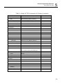
Table 5-1. Model 397 SCPI Commands List Summary
Keyword
Parameter Form (Default in Bold)
Notes
:INSTRument
[:SELect]
1|2
:COUPle
[:STATe]
OFF | ON
:MODE
MASTer | SLAVe
:PHASe
[:OFFSet]
(0,0,4M)
4 point increments
:OUTPut
[:STATe]
OFF | ON
:FILTer
[:LPASs]
NONE | 25M | 50M | ALL
:SYNC
[:STATe]
OFF | ON
:SOURce
BIT | LCOMplete
:POSition
[:POINt]
:WIDTh
(0;0;4M)
4 point increments
(4;4;100000)
4 point increments
[:SOURce]
:APPLy
5-8
FREQ,AMPL,OFFS
:SINusoid
FREQ,AMPL,OFFS,PHAS
:TRIangle
FREQ,AMPL,OFFS,PHAS
:SQUare
FREQ,AMPL,OFFS,DCYC
:PULSe
FREQ,AMPL,OFFS,DEL,WIDT,LEAD,TRA
:RAMP
FREQ,AMPL,OFFS,DEL,LEAD,TRA
:SINC
FREQ,AMPL,OFFS, NCYC
: GAUSsian
FREQ,AMPL,OFFS,EXP
: EXPonential
FREQ,AMPL,OFFS,EXP
: DC
DC_AMPL
: USER
SEGM,SCLK,AMPL,OFFS
Remote Programming Reference
SCPI Syntax and Styles
5
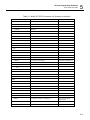
Table 5-1. Model 397 SCPI Commands List Summary (continued)
Keyword
Parameter Form (Default in Bold)
Notes
:FREQuency
[:CW]
(1e6;100e-6;50e6) | MINimum | MAXimum
:RASTer
(1e7;100e-3;125e6) | MINimum | MAXimum
:SOURce
INTernal | EXTernal
:DIVider
(1;1;65535)
Integers only
:ROSCillator
:SOURce
INTernal | EXTernal
:PHASe
[:OFFSet]
(0;0;4M)
1 point increments
:VOLTage
[:LEVel]
[:AMPLitude]
(5.000;10E-3;10.00) | MINimum | MAXimum
:OFFSet
(0;-4.5;+4.5)
:FUNCtion
:MODE
FIXed | USER | SEQuence
:SHAPe
SINusoid | TRIangle | SQUare | PULSe | RAMP |
SINC | GAUSsian | EXPonential | NOISe | DC
:SINusoid
:PHASe
(0;0;360)
:TRIangle
:PHASe
(0;0;360)
:SQUare
:DCYCle
(50;1;99)
:PULSe
:DELay
(10;0;99.9)
:WIDth
(10;0;99.9)
:TRANsition
[:LEADing]
(10;0;99.9)
:TRAiling
(10;0;99.9)
5-9
397
User Manual
Table 5-1. Model 397 SCPI Commands List Summary (continued)
Keyword
Parameter Form (Default in Bold)
:RAMP
:DELay
(0;0;99.9)
:TRANsition
[:LEADing]
(60;0;99.9)
:TRAiling
(30;0;99.9)
:GAUSsian
:EXPonent
(20;10;200)
:SINC
:NCYCle
(10;4;100)
:EXPonential
:EXPonent
(1;-20.00;20.00)
:DC
[:AMPLitude]
(100;-100;100)
:FM
:DATA
<arbitrary_block>
:DEViation
(10e6;100e-3;125e6)
:FUNCtion
:MODE
FIXed | USER
:SHAPe
SINusoidal | TRIangle | SQUare | RAMP
:FREQuency
:RASTer
[:STATe]
(1e3;1e-3;100e3)
(1e6;1e-3;2e6)
OFF | ON
:TRIGger
:MODE
CONTinuous | TRIGgered | GATed
:SLOPe
POSitive | NEGative
:FSK
:FREQuency
:RASTer
(80e6;100e-3;125e6)
[:STATe]
OFF | ON
:MODE
HOP | RAMP
:RAMP
:TIME
5-10
(1e-3;10e-6;1)
Notes
Remote Programming Reference
SCPI Syntax and Styles
5
Table 5-1. Model 397 SCPI Commands List Summary (continued)
Keyword
Parameter Form (Default in Bold)
Notes
:SWEep
[:FREQuency]
:STOP
(20e6;100e-3;125e6)
[:STATe]
OFF | ON
:TIME
(1e-3;1e-3;1000)
:DIRection
UP | DOWN
:SPACing
LINear | LOGarithmic
:TRIGger
CONTinuous | TRIGgered | GATed
:MODE
CONTinuous | TRIGgered | GATed
:SLOPe
POSitive | NEGative
:MARKer
(64e6;100e-3;125e6)
:AM
[:STATe]
OFF | ON
:TRACe
[:DATA]
<arbitrary_block>
DEFine
(1;1;2048,(16;16;4193304)
Even number, divisible by 4
:DELete
[:NAME]
(1;1;2048)
:ALL
:SELect
(1;1;2048)
:SEGMent
[:DATA]
<binary_block>
:DMA
[:STATe]
OFF|ON
:TYPE
WAVE | FM
OFF is automatic
:SEQuence
[:DATA]
<binary_block>
:ADVance
AUTOmatic | STEP | SINGle | MIXed
:SOURce
:DEFine
EXTernal | INTernal
(1;1;2048),(1;1;2048),(1;1;1E6),(0,0,1)
Step, segment, repeat,
advance mode
:DELete
:ALL
5-11
397
User Manual
Table 5-1. Model 397 SCPI Commands List Summary (continued)
Keyword
Parameter Form (Default in Bold)
Notes
:INITiate
[:IMMediately]
:CONTinuous
ON | OFF
:TRIGger
:BURSt
[:STATe]
:COUNt
OFF | ON
(1;1;1E6)
:SOURce
:ADVance
EXTernal | INTernal
:GATE
[:STATe]
OFF | ON
:SLOPe
POSitive | NEGative
:TIMer
(1e3;10e-3;2e6)
In Hz units
:PHASe
(0;0;4M)
4 point increments
[:IMMediate]
:ARM
[:STATe]
OFF | ON
:SLOPe
[:STARt]
POSitive | NEGative
:BREakpoint
:POSition
(0;0;4M)
4 point increments
:RESet
:SYSTem
5-12
:ERRor?
Query only
:VERSion?
Query only, 1999.0
Remote Programming Reference
SCPI Syntax and Styles
5
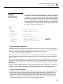
Table 5-1. Model 397 SCPI Commands List Summary (continued)
Keyword
Parameter Form (Default in Bold)
Notes
*CLS
*ESE
(0;0;255)
*OPC
*RST
*SRE
(0;0;255)
*TRG
*ESE?
Query only
*ESR?
Query only
*IDN?
Query only
*OPC?
Query only
*OPT?
Query only
*SRE?
Query only
*STB?
Query only
5-13
Remote Programming Reference
TRACe Subsystem
TRACe
Subsystem
The TRACe subsystem contains commands, which allow definition
of segments and their corresponding lengths, addition and deletion
of segments, and the loading of waveform data. Sequence
commands control segments link and loops. DMA command places
397 in a special data transfer mode where the generator’s
message-based interface is bypassed and data is loaded directly
from the data bus. Optional nodes were omitted from these
commands. Defaults are shown in bold.
Keyword
Limit
Parameter Form
:TRACe
:DEFine
:DELete
:DELete:ALL
:SELect (?)
#<header><binary_block>
<segment_number>,<length>
<segment_number>
:SEQuence
:ADVance (?)
:SOURce (?)
:DEFine
:DELete:ALL
5
Default,Low
Limit,High
<segment_number>
#<header><binary_block>
{AUTOmatic|STEP|SINGle|MIXed}
{EXTernal|INTernal}
<link>,<seg_#>,<loop>,<mode>
AUTOmatic
EXTernal
Generating Arbitrary Waveforms
Arbitrary waveforms are generated from digital data points, which are stored in memory. Each data point
has a vertical resolution of 14 bits (16384 points), i.e., each sample is placed on the vertical axis with a
precision of 1/16384. The Model 397 has the following waveform memory capacity:
4 Meg – standard memory configuration
Each horizontal point has a unique address - the first being 00000 and the last depends on the memory
option. In cases where smaller waveform lengths are required, the waveform memory can be divided into
smaller segments.
When the instrument is programmed to output arbitrary waveforms, the clock samples the data points
(one at a time) from address 0 to the last address. The rate at which each sample is replayed is defined
by the sample clock rate parameter. The 397 provides programmable sample clock rates from 100mS/s
to 125MS/s.
Unlike the built-in standard waveforms, arbitrary waveforms must first be loaded into the instrument's
memory. Correct memory management is required for best utilization of the arbitrary memory. An
explanation of how to manage the arbitrary waveform memory is given in the following paragraphs.
Arbitrary memory Management
The arbitrary memory in comprised of a finite length of words. The maximum size arbitrary waveform that
can be loaded into memory is 4M. Waveforms are created using small sections of the arbitrary memory.
The memory can be partitioned into smaller segments (up to 4096) and different waveforms can be
loaded into each segment, each having a unique length. Minimum segment size is 16 points, as long as
its playback time is more than 10µs. Information on how to partition the memory, define segment length
and download waveform data to the 397 is given in the following paragraphs.
5-47
397
User Manual
TRACe#<header><binary_block>
Purpose
This command will download waveform data to the 397 memory. Waveform data is loaded to the 397
using high-speed binary transfer. A special command is defined by IEEE-STD-488.2 for this purpose.
High-speed binary transfer allows any 8-bit bytes (including extended ASCII code) to be transmitted in a
message. This command is particularly useful for sending large quantities of data. As an example, the
next command will download to the generator an arbitrary block of data of 1024 points
TRACe#42048<binary_block>
This command causes the transfer of 2048 bytes of data (1024 waveform points) into the active memory
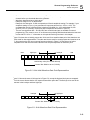
segment. The <header> is interpreted this way:
• The ASCII "#" ($23) designates the start of the binary data block.
• "4" designates the number of digits that follow.
• "2048" is the even number of bytes to follow.
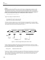
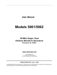
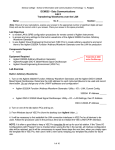
The generator accepts binary data as 14-bit integers, which are sent in two-byte words. Therefore, the
total number of bytes is always twice the number of data points in the waveform. For example, 20000
bytes are required to download a waveform with 10000 points. The IEEE-STD-488.2 definition of Definite
Length Arbitrary Block Data format is demonstrated in Figure 5-1.
"#"
non-zero
ASCII digit
ASCII digit
low byte
(binary)
high byte
(binary)
Start of
Data Block
Number of
to Follow
Byte Count:
2 x Number of
2 Byts Per
Data Point
Figure 5-1. Definite Length Arbitrary Block Data Format
Transfer of definite length arbitrary block data must terminate with the EOI bit set. This way, carriagereturn (CR – 0dH) and line feed (LF – 0aH) characters can be used as waveform data points and will not
cause unexpected termination of the arbitrary block data.
•
<binary_block>
Represents waveform data.
The waveform data is made of 16-bit words however, the GPIB link has 8 data bas lines and accepts 8bit words only. Therefore, the data has to be prepared as 16-bit words and rearranged as two 8-bit words
before it can be used by the 397 as waveform data points. The following description shows you how to
prepare the data for downloading to the 397. There are a number of points you should be aware of
before you start preparing the data:
5-48
Remote Programming Reference
TRACe Subsystem
5
1. Each channel has its own waveform memory. Therefore, make sure you selected the correct active
channel before you download data to the generator
2. Waveform data points have 14-bit values
3. Data point range is 0 to 16,383 decimal
4. Data point 0 to data point 16,383 corresponds to full-scale amplitude setting. For example, if your
amplitude setting is 5Vpk-pk, your generator will output waveforms from –2.5V to +2.5V. The
corresponding level in waveform points is decimal 0 (0x0000) for –2.5V and decimal 16,393
(0x3FFF) for 2.5V. Similarly, the 0V point will correspond to decimal 8191 (0x1FFF)
5. The two most significant bits – D14 and D15 are control bits and are not available for normal
programming. They must be set to “0” at all times except during DMA download where the last word
is sent with D15 set to “1”. Information on this special mode is given later in this chapter
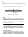
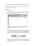
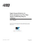
Figure 5-2 shows how to initially prepare the 16-bit word for a waveform data point. Note that there are
14 bits used for data representation. The other two bits are used for control purpose and must be set to
“0”. Also note that the 397 can not accept formats as shown in Figure 5-2; Data has to be further
manipulated to a final format that the instrument can accept and process as waveform point.
MSB
high-byte
D15 D14
D13 D12
LSB
low-byte
D11 D10
D9
D8
D7
D6
D5
D4
D3
D2
D1
D0
14-bit binary value (0 to 16383 decimal)
2 control bits. Must be set to 0, initially
Figure 5-2. 16-bit Initial Waveform Data Point Representation
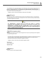
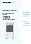
Figure 5-3 shows the same 16-bit word as in Figure 5-2, except the high and low bytes are swapped.
This is the correct format that the 397 expects as waveform point data. The first byte to be sent to the
generator is the low-byte and then high-byte.
low-byte
D7
D6
D5
D4
D3
high-byte
D2
D1
D0
D15
D14
D13
D12
D11
D10
D9
D8
2 control bits. Must be set to 0, initially
Figure 5-3. 16-bit Waveform Data Point Representation
5-49
397
User Manual
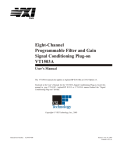
As an example, Figure 5-4 shows word value of decimal 8025 (0x1F59) in a correct format for
downloading to the 397. The byte containing 59 is sent first and then the byte containing 1F.
low-byte
0
1
0
5
1
1
high-byte
0
0
1
0
9
0
0
1
1
1
1
1
1
F
Control Bits = 0
Figure 5-4. 0x1F59 Data Point Representation
TRACe:DEFine<segment_number>,<length>
Purpose
This command will define waveform segments and their relative length. Note that if you are using the
TRAC:DATA# header to download waveform data, there is no need for this command because the
header contains segment size information and therefore, the segment will resize automatically. The use
of this command is absolutely a must if you truncate waveforms and download to the instrument as one
waveform.
•
•
<segment_number> will set the selected segment
<length> will assign length to the above selected segment. Minimum segment length is 16 points, the
maximum is limited by the memory size - 4M.
Note
The 397 operates in interlaced mode where four memory cells generate one byte of
data. Therefore, segment size can be programmed in numbers evenly divisible by
four only. For example, 2096 bytes is an acceptable length for a binary block. 2002
is not a multiple of 4, therefore the generator will generate an error message if this
segment length is used.
TRACe:DELete<segment_number>
Purpose
This command will delete a segment. The memory space that is being freed will be available for new
waveforms as long as the new waveform will be equal or smaller in size to the deleted segment. If the
deleted segment is the last segment, then the size of another waveform written to the same segment is
not limited. For example, let consider two segments, the first being a 1000-point waveform and the
second with 100 points. If you delete segment 1, you can reprogram another waveform to segment 1 with
5-50
Remote Programming Reference
TRACe Subsystem
5
size to 1000 points. If you reprogram segment 1 with 1004 points, the instrument will generate an error
and will not accept this waveform. On the other hand, if you delete segment 2, which was the last
segment you programmed, then you can reprogram this segment with waveforms having length limited
only by the size of the entire memory space.
•
<segment_number> will select the segment number that will be deleted
TRACe:DELete:ALL
Purpose
This command will delete all segments and will clear the entire waveform memory. This command is
particularly important in case you want to de-fragment the entire waveform memory and start building
your waveform segments from scratch.
Tip
The TRAC:DEL:ALL command does not re-write the memory so, whatever
waveforms were downloaded to the memory are still there for recovery. The
TRAC:DEL:ALL command clears the segment table. You can recover memory
segments by using the TRAC:DEF command. You can also use this technique to
resize, or combine waveform segments.
TRACe:SELect<segment_number>
Purpose
This command will select the active waveform segment for the output. By selecting the active segment
you are performing two function:
1. Successive :TRAC commands will affect the selected segment
2. The SYNC output will be assigned to the selected segment. This behavior is especially important for
sequence operation, where multiple segments form a large sequence. In this case, you can
synchronize external devices exactly to the segment of interest
•
<segment_number> will set the active waveform segment number
Parameter type
Numeric (integer only)
Parameter range
<segment_number>
1 to 2048
TRACe:SELect?
Response
The 397 will return the active segment number.
5-51