1
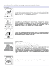
DJ SERIES
DJA 100
STEREO POWER AMPLIFIER
DJA 100
0
I
P R O F E S S I O N A L
-10
1
2
3
INPUT SELECT
4
+10
BASS
-10
+10
TREBLE
EQ
0
10
0
L-CH
10
R-CH
DJ SERIES
POWER
VOLUME
STEREO POWER AMPLIFIER
USER MANUAL
STEREO POWER AMPLIFIER
DJA 100
0
I
P R O F E S S I O N A L
-10
1
2
3
4
+10
BASS
INPUT SELECT
7
9
10 11
14
-10
+10
TREBLE
EQ
0
10
0
L-CH
10
R-CH
DJ SERIES
POWER
VOLUME
8
12
13
Pg 2
1
Operating Elements and Connections
1.1 Front panel
1 Input selector switches for selecting one of the
four inputs INPUT (12)
2 Controls L-CH and R-CH for the output levels of
the left and right channels
3 LEDs CLIP, light up in case of overload
4 LED PROTECT, lights up with the protective circuit activated:
1. in case of a short circuit at a speaker output
2. in case of overheating of the amplifier
5 Power LED ON
6 POWER switch
7 Bass - low frequency can be cut or boosted by
this control.
8 Treble - High frequency can be cut or boosted by
this control.
The wires in the mains lead of the power supply unit
are coloured in accordance with the following code:
green/yellow = earth
blue = neutral
brown = live
As the colours of the wires in the mains lead of this
appliance may not correspond with the coloured
markings identifying the terminals in your plug,
6
Operation
6.1 Switching on and off
To prevent loud switching noise, always switch on all
other units of the amplifer system before switching
on the power amplifier. After operation, switch off the
power amplifier first. Prior to switching on the amplifier for the first time, set the controls L-CH and R-CH
(2) to the left stop to minimum. Then switch on the
amplifier with the switch POWER. The power LED
ON (5) lights up as a power indication.
1. The wire which is coloured green and yellow
must be connected to the terminal in the plug
which is marked with the letter E or by the earth
symbol , or coloured green or green and yel6.2 Input selection
low.
Select the unit desired for reproduction with the
2. The wire which is coloured blue must be conswitches INPUT SELECT (1). To prevent loud
nected to the terminal which is marked with the
switching noise, only actuate the switches with the
letter N or coloured black.
volume turned down.
3. The wire which is coloured brown must be connected to the terminal which is marked with the
letter L or coloured red.6.3 Level adjustment
Only turn up the controls L-CH and R-CH (2) as
Warning This appliance must be earthed.
necessary until the maximum volume desired is
reached. The red LEDs CLIP (3) will indicate over3 Applications
load of the amplifier. In this case, slightly turn back
This PA stereo amplifier with a peak power of
the controls.
300 WMAX is specially designed for stage and disco
Caution!
applications. It allows connection of up to four audio
Never adjust the amplifier to a very high volume.
units. Via the input selector switches it is possible to
Permanent high volumes may damage your hearselect a unit for reproduction.
ing! The human ear will get accustomed to high
volumes which do not seem to be that high after
4 Installation
some time. Therefore, do not further increase a
high volume after getting used to it.
The amplifier is designed for installation into a rack
(482 mm/19"), however, it can also be used as a
table-top unit. In any case, air must be allowed to
7 Protective Circuit
flow past the lateral cooling ribs without obstruction
The protective circuit is provided to prevent damage
to ensure a sufficient cooling of the amplifier.
to the amplifier. If this circuit is activated, the yellow
LED PROTECT (4) will light up:
4.1 Rack installation
1. in case of a short circuit at a speaker output
For rack installation, 1 RS (rack space = 44.5 mm) is
2. in case of overheating of the amplifier.
required. It is recommended to leave additional
If the yellow LED PROTECT lights up, switch off the
space above and below the amplifier to ensure a
sufficient cooling. In case of insufficient heat dissipa- amplifier and eliminate the fault.
tion,insert a ventilation unit in to the rack above the
amplifier. Otherwise there will be a heat accumulation within the rack which may not only damage the
8 Specifications
amplifier but also other units in the rack.
RMS output power
To prevent top-heaviness of the rack, the amplistereo 4 : . . . . . . . . . . . 2 x 110 W
fier must be installed in the lower part of the rack.
stereo 8 : . . . . . . . . . . . 2 x 80 W
The front panel alone will not suffice for securing the
Maximum output power: . . . 300 W
amplifier. An additional base plate must be provided
for supporting the unit.
Inputs: . . . . . . . . . . . . . . . . . 0.775 V/10 kΩ
Frequency range: . . . . . . . . 20 – 20 000 Hz
Equalizer: . . . . . . . . Bass +- 10dB @ 100 Hz
5 Connecting the Amplifier
. . . . . . . . Treble +- 10dB @ 100 Hz
Always switch off the unit before making any
S/N ratio: . . . . . . . . . . . . . . > 70 dB
connections!
Crosstalk attenuation: . . . . . > 50 dB
1) Connect the line outputs of up to four audio units
THD: . . . . . . . . . . . . . . . . . . < 0.5 %
(e. g. preamplifier, mixer) to the phono jacks
INPUT (13): white jack = left channel, red jack =
Power supply: . . . . . . . . . . . 230 V~/50 Hz
right channel.
Power consumption: . . . . . . 450 VA
2) The highest output power is obtained when conAmbient temperature: . . . . . 0 – 40 °C
necting 4 speakers. However, it is also possible
Dimensions (W x H x D): . . 482 x 44.5 x 285 mm,
to connect 8 speakers. In this case, the output
1 RS (rack space)
power will be slightly reduced. The minimum
Weight: . . . . . . . . . . . . . . . . 7.2 kg
RMS power capability of the speakers must be:
-
1.2 Rear panel
9 Mains cable for connecting 230 V~/50 Hz
10 Fuse holder; replace a burnt-out fuse by one of
the same type only
11 Clamping screw for a potential ground connection
12 Speaker terminals OUTPUT (6.3 mm jacks)
13 Input jacks INPUT (phono jacks)
for units with line level (e. g. mixer, preamplifier)
14 Speaker terminals OUTPUT
(Spring-loaded terminals)
Note :- Connect 4Ω speakers either to springLoaded terminals or to the 6.5 mm jacks(12). 8Ω
Speakers may be operated simultaneously at the
Spring - loaded terminals and at the 6.3 mm jacks.
2
Safety Notes
This unit corresponds to the directive for electromagnetic compatibility 89/336/EEC and to the low
voltage directive 73/23/EEC.
The unit is supplied with hazardous mains
voltage (230 V~). Leave servicing to skilled
personnel only. Inexpert handling may cause
an electric shock hazard. Furthermore, any
guarantee claim will expire if the unit has
been opened.
Always switch off the unit before making or
changing any connections.
Please observe the following items in any case:
The unit is suitable for indoor use only. Protect it
against dripping water and splash water, high air
humidity, and heat (admissible ambient temperature range 0 – 40 °C).
Do not place any vessel filled with liquid on the
unit, e. g. a drinking glass.
Be careful during transport! Do not seize the
unit by the lateral cooling ribs; they are sharpedged and may cause injuries.
Do not operate the unit or immediately disconnect
the plug from the mains socket
1. if there is visible damage to the unit or to the
mains cable,
2. if a defect might have occurred after the unit
was dropped or suffered a similar accident,
3. if malfunctions occur.
In any case the unit must be repaired by skilled
personnel.
A damaged mains cable must be replaced by the
manufacturer or authorized, skilled personnel only.
Never pull the mains cable when disconnecting the
mains plug from the socket, always seize the plug.
For cleaning only use a dry, soft cloth; never use
chemicals or water.
No guarantee claims for the unit or liability for any
resulting personal damage or material damage will
be accepted if the unit is used for other purposes
If the unit is to be put out of operation definitively,
take it to a local recycling plant for a disposal
which is not harmful to the environment.
4
8
speakers 110 W
speakers 80 W
Connect the speakers to the 6.3 mm jacks (12)
For simultaneous operation of speakers at the
6.3 mm jacks and at the spring loaded terminals ,
only use speakers of minimum impedance
of 8 , otherwise this will result in overload of the
amplifier.
When using the terminals, connect each
marked core of the speaker cables to a red terminal.
Possibilities for connecting several speakers to
One channel are shown in figures 4 - 7. When interconnecting several speakers, it is essential to
observe the correct positive and negative connections and the minimum total impedance of 4W.
3) Finally connect the plug of the mains cable (9) to
a mains socket (230 V~/50 Hz).
Possibilities for connecting several speakers to
According to the manufacturer.
Subject to technical modification.
Pg 3
Do not attempt to make any repairs yourself. This would invalid your warranty.
Do not make any changes to the unit. This would also invalid your warranty.
The warranty is not applicable in case of accidents or damages caused by inappropriate use or
disrespect of the warnings contained in this manual.Studiomaster can not be held responsible for
personal injuries caused by a disrespect of the safety recommendations and warnings. This is also
applicable to all damages in whatever form.
MANUFACTURER: UNISOUND PVT. LTD.
Unit 17, SDF-1, Seepz,
Andheri (E), Mumbai 400096
E-mail: [email protected]
We reserve the right to make modifications to its products without notice
-4-
LIT MA 1Q2 - 0