1
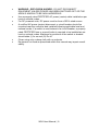
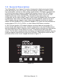
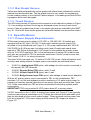
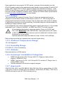
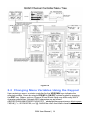
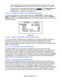
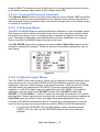
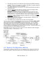
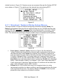
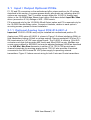
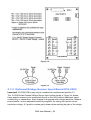
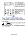
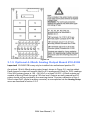
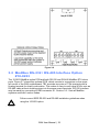
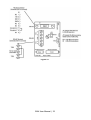
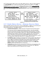
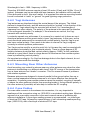
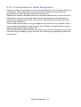
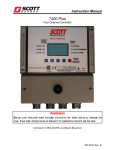
USER MANUAL WX 4 Four Channel Controller P/N: 77036021-1 Revision: 1.1 Reference Firmware: 1.25 (rev. 4.1) The Fixed Gas Detection Experts WX4 User Manual | 2 THE INFORMATION CONTAINED IN THIS MANUAL IS ACCURATE TO OUR KNOWLEDGE. As a result of continuous research and development, the specifications of this product may be modified at any time without prior notice. IMPORTANT INFORMATION The modification of the material and the use of parts of an unspecified origin shall entail the cancellation of any form of warranty. The use of the unit has been projected for applications specified in the technical characteristics. Exceeding the values cannot in any case be authorized. LIABILITY Neither Oldham nor any other associated company can be held liable for any damages, including, without limitations, damages for the loss or interruption of manufacture, loss of information, defect of the WX4 unit, injuries, loss of time, financial, or material loss, or any direct or indirect consequence of loss occurring in the context of the use or impossibility of use of the product, even in the event that Oldham has been informed of such damage. SAFETY INSTRUCTIONS Labels intended to remind you of the principal precautions of use have been placed on the unit in the form of pictograms. These labels are considered an integral part of the unit. If a label falls off or becomes illegible, see to it that it is replaced. Warning: Read & understand contents of this manual prior to operation. Failure to do so could result in serious injury or death. WX4 User Manual | 3 WX4 User Manual | 4 Table of Contents SECTION - 1 . Important Safety Issues 1.0 General Description 1.1 Data Display Screens 1.1.1 Engineering Unit Screen 1.1.2 Bar Graph Screen 1.1.3 Trend Screen 1.2 Specifications 1.2.1 Power Supply Requirements 1.2.2 Relays 1.2.3 Ambient Temperature Range 1.2.4 Humidity Range 1.2.5 Altitude 1.2.6 Housings / Installation Categories 1.2.7 Approvals 7 7 9 10 10 11 11 11 11 12 12 12 12 12 12 SECTION - 2 . 2.0 Basic Operation 2.1 Setup Menu Configuration 2.2 Changing Menu Variables Using the Keypad 2.2.1 WX4 Setup Configuration Menus 2.2.2 Channel Setup Entry Menu 2.2.3 FAULT / ALARM 1 / ALARM 2 / ALARM 3 SET-UP Menus 2.2.4 Configure Menu to Define Channel 2.2.5 Cal Setup Menu 2.2.6 Calibrate Input Menu 2.3 System Configuration Menus 2.3.1 Standard / Optional Relay Setup Menus 2.3.2 Relay 2 ACK (Acknowledge) / Horn Setup Menu 2.3.3 Clock / Delays Menu 2.3.4 Communications Menu 2.3.5 Analog Setup Menu 2.4 System Security Menu 13 13 13 14 15 15 16 17 18 18 19 20 21 21 22 22 23 SECTION - 3 . 3.0 Motherboard Interface PCB #10-0215 3.1 Input / Output Optional PCBs 3.1.1 Optional Analog Input PCB #10-0221-4 3.1.2 Optional Bridge Sensor Input Board #10-0309 3.1.3 Bridge Sensor Initial Setup 3.1.4 Optional Discrete Relay PCBs #s 10-0222 3.1.5 Optional 4-20mA Analog Output Board #10-0308 3.2 ModBus RS-232 / RS-485 Interface Option #10-0253 25 25 27 27 28 29 30 31 32 WX4 User Manual | 5 3.2.1 ModBus Register And Function Code Summary 3.3 Optional 24 VDC 50 Watt Power Supplies 34 40 SECTION - 4 . 4.0 NEMA 4x Polycarbonate Wall Mount (Extended) 4.1 NEMA 4 Painted Steel Wall Mount (Extended) 4.2 NEMA 4x Stainless Steel Wall Mount (Extended) 4.3 NEMA 7 Explosion-Proof Wall Mount (Extended) 41 41 42 43 44 SECTION - 5 . 5.0 Adding the “Wireless” Radio Kit Option 5.1 Radio Setup Menu 5.2 Wireless Receiver Mode 5.2.1 Radio Status Alarms – Wireless Receiver Mode 5.3 Wireless ModBus Slave Mode 5.4 Antenna Selection 5.4.1 Dipole and Collinear Antennas 5.4.2 Yagi Antennas 5.4.3 Mounting Near Other Antennas 5.4.4 Coax Cables 5.5 Surge Protection and Grounding 5.5.1 Antenna Grounding 5.5.2 Connections to Other Equipment 45 45 46 46 47 48 48 48 49 49 49 50 50 51 WX4 User Manual | 6 SECTION - 1 . Important Safety Issues The following terms and symbols are used in this manual to alert the operator of important instrument operating issues: This symbol is intended to alert the user to the presence of important operating and maintenance (servicing) instructions. This symbol is intended to alert the user to the presence of dangerous voltage within the instrument enclosure that may be sufficient magnitude to constitute a risk of electric shock. This symbol signifies the system’s ground terminal DC refers to direct current voltages. VAC refers to alternating current voltages. WARNINGS: Shock Hazard - Disconnect or turn off power before servicing this instrument. NEMA 4X wall mount models should be fitted with a locking mechanism after installation to prevent access to high voltages by unauthorized personnel (see Figure 4.0). Only the combustible monitor portions of this instrument have been assessed by CSA for 122.2 No. 152 performance requirements. This equipment is suitable for use in Class I, Division 2, Groups A,B,C and D or non-hazardous locations only. WARNING - EXPLOSION HAZARD - SUBSTITUTION OF COMPONENTS MAY IMPAIR SUITABILITY FOR CLASS I, DIVISION 2. WARNING - EXPLOSION HAZARD - DO NOT REPLACE FUSE UNLESS POWER HAS BEEN SWITCHED OFF OR THE AREA IS KNOWN TO BE NON-HAZARDOUS. WX4 User Manual | 7 WARNING - EXPLOSION HAZARD - DO NOT DISCONNECT EQUIPMENT UNLESS POWER HAS BEEN SWITCHED OFF OR THE AREA IS KNOWN TO BE NON-HAZARDOUS. Use a properly rated CERTIFIED AC power (mains) cable installed as per local or national codes. For DC powered units, DC power must be from a SELV rated source. A certified AC power (mains) disconnect or circuit breaker should be mounted near the controller and installed following applicable local and national codes. If a switch is used instead of a circuit breaker, a properly rated CERTIFIED fuse or current limiter is required to be installed as per local or national codes. Markings for positions of the switch or breaker should state (I) for on and (O) for off. Clean using only a damp cloth with no solvents. Equipment not used as prescribed within this manual may impair overall safety. WX4 User Manual | 8 1.0 General Description The OldhamWX4 Four Channel Controller is designed to display and control alarm event switching for up to four inputs. Inputs are typically voltage or 4-20mA current from transmitters, monitors or other analog output devices. The WX4 is equipped with a Fault and three alarm levels per channel with features such as ON / OFF delays, latching relays and alarm Acknowledge. A dedicated horn driver circuit for a local audible annunciator is also standard. Two standard 5-amp alarm relays are configurable via the “alarm voting” menu to make relays trip based upon various alarm combinations. Real-Time Clock and Calendar are also standard. Options such as 420mA outputs, discrete relays for each alarm and audible annunciators are easily added. RS-485 (ModBus RTU) or Ethernet (ModBus TCP) ports are also available for sending data to PC’s, PLC’s, DCS’s, or other Oldham WX-Series controllers. A 128 x 64 pixel graphic LCD readout displays monitored data as bar graphs, 30minute trends and engineering units. System configuration is via user friendly menus and all configuration data is retained in non-volatile memory during power interruptions. The WX4 front panel is shown below in Figure 1.0 displaying the bar graph data screen. The five button symbols below the display are magnetically activated using the supplied magnetic wand without opening the enclosure. Opening the enclosure door provides access to the “touch” keypad as shown in Figure 1.1. Figure 1.0 WX4 User Manual | 9 Figure 1.1 1.1 Data Display Screens The WX4 Controller offers three modes for displaying monitored data. Each is shown below in Figure 1.2. Figure 1.2 1.1.1 Engineering Unit Screen The WX4 Engineering Unit screen shown at left in Figure 1.2 allows each channel’s value and its 10-digit Eunits tag to be viewed simultaneously. A1, A2, A3, FL icons at lower right of each reading flash if ALARM 1, 2, 3 or FAULT alarms activate for this channel. WX4 User Manual | 10 1.1.2 Bar Graph Screen Values are displayed graphically as bar graphs with alarm levels indicated by vertical dashed lines across each bar. The bar graph screen is very useful for emphasizing current reading relative to the channel’s alarm setpoint. Live readings and their Eunits tag appear above each bar graph. 1.1.3 Trend Screen The WX4 also provides 30-minute trend screens for each channel as shown in Figure 1.2. Live readings and their Eunits tag are displayed across the top of each trend screen. Channel numbers are shown in the upper right and are selected by the NEXT key. A1. A2 and A3 alarm levels appear as horizontal dashed lines across the screen. 1.2 Specifications 1.2.1 Power Supply Requirements WX4 primary power may be either 10-30 VDC or 100-240 VAC. All models are equipped with an AC input / 24 VDC 15 watt output switching power supply PS1 mounted to the motherboard (see Figure 3.1). AC power requirements are 100-240 VAC 50/60 Hz @ .80 amp max (including inrush) and 40 watts max steady state, applied to TB5 on the motherboard. If AC power is not available the primary power may be 10-30 VDC applied to TB1 on the motherboard. A backup DC power source may also be connected to TB1 for automatic switchover if the AC power source fails. See Figures 3.0 & 3.1 for wiring information. The basic WX4 consumes only 1.5 watts of 10-30 VDC power. Optional features such as relays and analog outputs increase power consumption as described below: 10-0221-4, Analog Input PCB option; add wattage for each monitor connected to this board’s 24 VDC terminals. 10-0222, Discrete Relay PCB option; add 1.5 watt. 10-0308, 4-20mA Output PCB option; add 1 watt. 10-0309, Bridge Sensor Input PCB option; add wattage of each sensor attached. With an AC primary power source connected to TB1 on the motherboard, TB3 terminals 1 & 2 on the motherboard provide a maximum of 12 watts output power for powering of auxiliary external devices such as relays, lights and monitors (see Figure 3.0). Power consumed from TB3 must be included when calculating system power consumption. IMPORTANT! TB3 only provides 24 VDC power when AC is primary power. 24 VDC terminals on the 10-0221-4 Analog input option (see Figure 3.3) are typically used to power external transmitters up to 10 watts per channel and these loads must also be calculated into the overall power budget. These terminals receive power from both the integral AC / DC power supply and the external TB1 supply as shown in Figure 3.0. WX4 User Manual | 11 Some applications may require 24 VDC power in excess of that available from the WX4 AC power supply on the motherboard and thereby require another 50 watt AC/DC supply. NEC Class 2 FIFTY WATT external supplies are available for Division 1 (part #10-0314) and Division 2 (part #10-0315) potentially hazardous area installations and both also include a NEMA 4X weather rating. Contact an Oldham sales representative or visit http://www.oldhamgas.com for more details. 1.2.2 Relays Two mechanical (dry contact) Common Form C relays are standard and may be mapped to various alarm events as described in section 2.3.1. WX4’s may also be equipped with optional solid-state common Form A relays (see order guide for details) in applications requiring non-arcing switching. Solid-state relays are recommended for switching of highly inductive loads. A six mechanical (dry contact) Discrete Relay option board (see section 3.1.6) provides dedicated Form C relays for ALARM 1, ALARM 2 and FAULT for both channels. All mechanical (dry contact) relays are rated at 5 Amp for 28 VDC and 250 ~VAC RESISTIVE loads. IMPORTANT: Appropriate diode (DC loads) or MOV (AC loads) snubber devices must be installed with inductive loads to prevent RFI noise spikes. Optional solid state relays are rated at 2 Amp 12-280 ~VAC (600Vpk). Relay wiring should be kept separate from low level signal wiring. 1.2.3 Ambient Temperature Range -25 to 60 degrees C 1.2.4 Humidity Range 0 TO 90% R. H. Non-Condensing. 1.2.5 Altitude Recommended up to 2000 meters 1.2.6 Housings / Installation Categories NEMA 4X wall mount. DIV 2 Groups A,B,C,D; Category II and pollution degree 3; NEMA 4X; IP66 NEMA 7 wall mount for DIV 1 & 2 Groups B,C,D; includes ‘O’ Ring in door to satisfy NEMA 4 rating. Includes standard non-intrusive magnetic keypad. 1.2.7 Approvals CSA C22.2 No 1010.1 and ISA S82.02; CSA C22.2 No 152 for combustibles; UL 1604 / C22.2 No 213 (Div 2 Groups A,B,C,D); EN55011 & EN61000 (CE Mark). CSA File # = 252022 and may be seen at: CSA-International.org. WX4 User Manual | 12 SECTION - 2 . 2.0 Basic Operation The WX4’s graphic LCD displays monitored data and with the 5-button keypad also serves as the system’s operator interface. All WX4 configuration variables are entered with this operator interface using SETUP menus accessed by pressing EDIT from either data screen. This Setup mode may be exited manually by pressing NEXT, or automatically when no keys are pressed for 5 minutes. Alarm relays and front panel alarm LED indicators remain active during the Setup mode. Alarm LED’s flash upon new alarms and become steady after Acknowledged by pressing the ALARM RESET key. A SECURITY menu offers a password feature to prevent tampering with WX4 parameters. A “sign-on” screen appears briefly after power is applied that indicates what type input / output options the unit is configured with. 2.1 Setup Menu Configuration Variables inside the CHANNEL (see section 2.2) and SYSTEM (see section 2.3) menu trees allow WX4 configuration for a wide range of monitoring applications. Select the desired menu by scrolling with UP/DOWN and then EDIT to enter each menu. Figure 2.0 illustrates the menus tree for configuring Channel and System specific variables. Channel variables affect only the specific channel selected while System variables are related to features not specific to any channel. WX4 User Manual | 13 Figure 2.0 2.2 Changing Menu Variables Using the Keypad Upon entering a menu, a pointer controlled by the UP/DOWN keys indicates the selected variable. Some are simple YES/NO or ON/OFF entries toggled by pressing the EDIT key. Others, such as Channel ID and Eunits fields may have many ASCII character possibilities. Allowed ASCII characters are as follows: ABCDEFGHIJKLMNOPQRSTUVWXYZ[\]^_`abcdefghijklmnopqrstuvwxyz blank space !”#$%&`()*+,-./0123456789:;<=>?@. Notice the often used blank character is located WX4 User Manual | 14 after lower case z and before the exclamation point !. EDIT places a cursor under the item and UP/DOWN scrolls through each allowed entry. The NEXT key moves the cursor to the next position within a field. When the field is complete, EDIT clears the cursor and loads the field into non-volatile memory where it is retained indefinitely. Without a cursor present, the NEXT key closes open menus in reverse order and returns the LCD to the data display. 2.2.1 WX4 Setup Configuration Menus The SETUP menu shown in the middle of Figure 2.0 and in Figure 2.1 below is reached by pressing EDIT with any data display present. This is the entry-level screen to ALL Channel, System and Security menus. It also shows the revision of firmware operating in the WX4. Use the UP/DOWN keys to move the pointer to the desired menu and press the EDIT key. Figure 2.1 2.2.2 Channel Setup Entry Menu The CHANNEL menu shown below in Figure 2.2 allows configuration of all variables for the selected channel. These are Fault, Alarm 1, Alarm 2, Alarm 3, Configure and CAL Setup. Figure 2.2 WX4 User Manual | 15 2.2.3 FAULT / ALARM 1 / ALARM 2 / ALARM 3 SET-UP Menus Alarms 1, 2 and 3 have identical menus. The only difference between each is A1 front panel LED indicators are yellow while A2 and A3 are red. Typical applications often have A1 set at a WARN level, A2 at a HIGH level and A3 at a higher SHUT DOWN level. However, it is important to understand there is no functional difference between A1, A2 and A3, and since their configuration menus are identical, only one is shown in Figure 2.3. The Fault menu is identical to A1, A2, A3 except Fault alarms are always low trips (alarm activates as input goes below the setpoint) and Fault alarms may not be set for latching operation. Figure 2.3 Set Point is entered in engineering units and determines the value where the alarm trips. For example, if a channel monitors 0-50 ppmH2S and the desired alarm level is 10 ppm, the correct entry is 10.00. A one percent dead band prevents alarm chatter. This means after tripping an alarm, the input must move at least 1% of full scale back through the setpoint for the alarm to auto reset. The ON Delay / OFF Delay entries allow ON and OFF time delays affecting how long the trip-point must be surpassed before an alarm event transition occurs. ON delays are limited to 10 seconds while OFF delays may be as long as 120 minutes. Delays are useful in many applications to prevent nuisance alarms and unwanted cycling into and out of alarm conditions. Low Trip is set for NO for increasing alarms or YES for decreasing alarms to determine if the alarm activates upon exceeding or falling below the setpoint. Latching determines either manual or automatic alarm reset operation. YES requires a manual Alarm Reset to unlatch the alarm even though an alarm condition no longer exists. YES also causes this alarm’s common relay, front panel LED, and optional discrete relay to latch. NO allows all outputs for this alarm to automatically reset after the alarm condition clears. Common alarm LED indicators on the left side of the front panel indicate the status of A1, A2 A3 alarms. The common Fault LED is on the lower right side WX4 User Manual | 16 of the front panel. Any new alarm event causes the associated LED to flash until an Alarm Reset occurs causing an acknowledged steady on condition. Operators should recognize new alarms by a flashing LED. Alarm Reset also acknowledges, or deactivates, audible devices driven by the AUDIBLE ALARM option connector J2 (see Figure 3.1). 2.2.4 Configure Menu to Define Channel The channel setup menu after the alarm menus is CONFIGURE. It allows setting Name and EUNIT 10 digit ASCII fields, defines the measurement range with ZERO & SPAN entries, number of Decimal Points of resolution the reading will have, and if the channel is Active. Figure 2.4 2.2.4.1 Name / EUNITS ASCII Data Fields The first two items in this menu are for entering the 10 character channel Name and engineering unit ASCII fields. Name should describe the channel’s data in user terminology such as tag # or other description. Eunits should define the units of measure for what this channel is to display. Section 2.2 describes how to modify these fields using the keypad. 2.2.4.2 Input Measurement Range The Zero / Span menu entries allow configuration of the measurement range displayed by this channel. Measurement Range defines the range of the input signal’s engineering units. For example, if a channel’s input is 4-20mA from a transmitter monitoring 0 to 10ppm chlorine, then the Zero value should equal 0.000 and the Span value equal 10.00. Four digits must be entered, so trailing 0’s may appear here that are not displayed on other data screens. These menus work hand in hand with Min/Max Raw Counts menus described in section 2.3.4. 2.2.4.3 Decimal Point Resolution Resolution of the displayed channel value is configured in this menu by setting the number digits trailing the decimal point. Displayed readings are limited to a maximum of four digits with a polarity sign. Auto-ranging displays the highest resolution allowed by this menu’s decimal point entry. For example, a range of 0 to 100ppm and two decimal points reads 0.00 at 0ppm and 100.0 at 100ppm. This may be undesirable due to the high resolution at zero unless the sensor’s output is extremely stable. If decimal points are limited to one, the 0ppm reading becomes 0.0 and the 100ppm reading WX4 User Manual | 17 remains 100.0. Resolution may be limited further by setting decimal points to 0 where in the above example, 0ppm reads 0 and 100ppm reads 100. 2.2.4.4 Turning Off Unused Channels The Channel Active? menu entry asks if this channel is to be utilized. OFF causes the controller to never process inputs applied to this channel and no alarms are tripped or data displayed. Inactive channels have a line drawn through them on the Setup screen to indicate it is turned off. 2.2.5 Cal Setup Menu The WX4 CAL MODE feature supports pushbutton calibration of zero and span values. This feature should be utilized only when there are no other zero/span controls within the monitoring system, since it is inappropriate to calibrate a signal at more than one point. Therefore, if calibration will be performed at another transmitter or monitoring device, the WX4 CAL MODE feature should not be used. The CAL SETUP menu allows entering the correct Zero & Span Gas setpoint values needed to calibrate the channel. These are entered in the same engineering units as input range. Figure 2.5 2.2.6 Calibrate Input Menu The CAL MODE (flow chart shown in Figure 2.6) is designed to make calibration quick, easy and error free. A successful ZERO and SPAN calibration requires only a few keystrokes. Optional 4-20mA outputs (if equipped) transmit 1.5mA during CAL MODE and 4mA during the subsequent CAL DELAY to prevent external alarms during calibration. Local WX4 alarm relays are inhibited during CAL MODE. Unintentional calibrations may be reset by the Set UNITY menu item. Set UNITY resets Cal OFFSET to 0 & Cal GAIN to 1, which is useful for returning the calibration to a known starting place. Sensor aging may be monitored by recording zero and span readings at Unity Gain when the sensor is new, and again later when degradation may have occurred. CAL MODE automatically exits if no keystroke is detected after 5 minutes. Use the following step-by-step procedure to perform ZERO and SPAN calibrations. 1. To enter the CAL MODE from any data display, press the dual purpose DOWN / CAL key then use the UP/DOWN keys to select the channel to calibrate. WX4 User Manual | 18 2. 3. 4. Stimulate the monitor to be calibrated with an appropriate ZERO calibration standard. Observe the screen’s live reading, and when it is stable, press the EDIT key to perform the ZERO calibration. If the ZERO calibration is successful, CAL MODE automatically proceeds to the SPAN check. Apply the correct SPAN calibration standard. After the reading is stable, press the EDIT key to perform a SPAN calibration. WARNING: The SPAN calibration standard used must match the value specified, since this is the reading the WX4 will indicate after a successful SPAN calibration. The SPAN calibration value may be edited if it becomes necessary to apply a different calibration standard to set SPAN (see Span Calibration in section 2.2.5). If the SPAN calibration is successful, the display flashes “REMOVE CAL GAS” and starts the CAL DELAY. 6. CAL MODE will be complete after the end of the CAL DELAY. The flow chart in Figure 2-6 illustrates the above procedure. UP, CAL, NEXT & EDIT labels indicate keystrokes (CAL/DOWN is a dual purpose key). The CAL MODE information screen (top of the chart) is available for advanced users to see Offset / Gain calibration constants and live analog to digital converter (A/D) counts. Span setpoint calibration values may also be edited from this screen. Holding the UP key for 5 seconds during CAL MODE displays this screen. Unity Gain may be used at any time to cancel incorrect calibrations and start again. Unity means Offset = 0.00 and Gain = 1.00. 5. Figure 2.6 2.3 System Configuration Menus Several items needing configuration are not specific to either channel but affect the entire WX4 system. These are located in the SYSTEM menus group shown in the WX4 User Manual | 19 dotted line box in Figure 2.0. System menus are accessed through the System SETUP menu shown in Figure 2.7 by pointing to the desired item and pressing EDIT. Figure 2.7 2.3.1 Standard / Optional Relay Setup Menus The menu shown in Figure 2.8 allows configuring of both the standard Relay 1 & Relay 2 motherboard relays and the six optional relays on the 10-0222 discrete relay option PCB. Both standard and optional relays are programmed in this menu. Select the relay to be configured by pointing the arrow at the top menu item and pressing EDIT. The field will scroll through all eight possible relays (2 standard and 6 optional). Figure 2.8 Fault, Alarm 1, Alarm 2, Alarm 3 menus in Figure 2.8 offer additional “voting” flexibility by controlling the channel alarm combinations that will trip the selected relay. Each Votes entry requires this quantity of channels for each type alarm be active before this relay activates. As illustrated in Figure 2.8 above, Standard Relay 1 activates when any 2 channels have Alarm 1 conditions, PLUS, any one channel has an Alarm 2 condition. And since the Over Ride menu (see description below) contains the Ch1A2 entry, Standard Relay 1 also activates if alarm 2 on channel 1 trips. Fault Votes and Alarm 3 Votes values are 0, therefore Fault and Alarm 3 conditions will not affect this relay. Votes follow the logical “AND” function. Failsafe set for YES causes this relay to be energized when its voting requirements are false (no alarm condition) and de-energized when the alarm vote requirements are true. The primary benefit of Failsafe is loss of power places the relay contacts into the alarm condition. WX4 User Manual | 20 “Over Ride” menu allows entering one of the 16 different alarms that will trip this relay regardless of the Votes entries. There are four alarms per channel and four channels, and any one of these alarms may be used as the Over Ride. This feature is useful when one channel’s alarm has more significance than the others. 2.3.2 Relay 2 ACK (Acknowledge) / Horn Setup Menu The Horn SETUP menu controls how each alarm type (Fault, and Alarms 1 through 3) will affect the horn driver circuit connected to J2 on the motherboard. Choices are OFF, STEADY or PULSE. Warning level alarms might be set to pulse the horn, with high alarms set for steady. Personnel then know which alarm level is present by hearing the pulsing or steady horn. Relay 2 Acknowledge set to ON allows Relay 2 to be deactivated during alarm conditions by an Alarm Reset. This is useful if another audible device is being driven by the relay. The acknowledge feature is not available for Relay 1, since it is often used for driving a warning light and Relay 2 for driving a horn. It could be dangerous if an operator acknowledged the horn AND the light since no indication of the high alarm condition remains. Local Piezo set to ON causes the tiny local piezo adjacent to the LCD to mimic the J2 horn output. Figure 2.9 2.3.3 Clock / Delays Menu These WX4 timers accommodate inputs that may require varying times to stabilize after power is applied and after calibrations are complete. Alarm Refresh menu allows reactivation of Acknowledged alarms after the time period expires. This feature is used primarily to restart audible alarm devices after having been silenced by an acknowledge function (via serial port or pressing the Alarm Reset button). An entry of 0 seconds effectively disables the Alarm Refresh function. Warm Up Delay menu allows setting how long alarm relays remain disabled after power is applied. Cal Delay determines how long alarm relays are inhibited after completing a calibration. WX4 User Manual | 21 Time and Date menu items are for setting the correct time and date. The WX4 is equipped with a 24-hour clock and calendar. Time of day must be entered in 24-hour mode. For example, 6:00:00 PM = is indicated as18:00:00. Figure 2.10 2.3.4 Communications Menu The COMM SETUP menu allows setting of the system’s ModBus Slave ID or RTU address (requires 10-0253 ModBus option PCB – see Section 3.2). This slave port may be used to transfer WX4 data to a ModBus master device such as a PC, PLC, DCS or even other Oldham WX-Series Controllers such as the 16 Channel WX16. The slave port is addressable, allowing many WX4 controllers to be connected to a single RS-485 cable. A converter is available to make this port also compatible with Ethernet TCP/IP networks. The entire ModBus database, including registers and supported Function Codes, is documented in section 3.2.1. See section 4 for COMM SETUP menu descriptions for WIRELESS WX4 networks. Figure 2.11 2.3.5 Analog Setup Menu The system ANALOG SETUP menus in Figure 2.12 allow setting the 11-bit A/D (analog to digital) counts and the 10-bit D/A (digital to analog) counts for each of the four channels. Use the Set Channel entry to scroll to the desired channel using the EDIT key. The live A/D counts value for the channel selected is also shown on the bottom of this screen. The default setting for A/D counts is 400 for Min and 2000 for Max. This is based upon a 0-20mA input providing 0-2000 counts, or, 100 counts per mA input. WX4 User Manual | 22 Min Counts / Max Counts entries in the INPUT SETUP menus define the input A/D counts range for Zero and Span readings as described in section 2.2.4b. The default settings for each analog channel are 400 to 2000 counts. Standard inputs yield 400 counts at 4mA and 2000 counts at 20mA but, for example, if a special application requires the Zero reading at 6mA input and the Span reading at 18mA input the correct A/D Min / Max Raw counts would be 600 to 1800.00. Min Counts / Max Counts entries in the OUTPUT SETUP menus define the output D/A counts range for Zero and Span readings as described in section 2.2.4b. OUTPUT SETUP menus are only used when the WX4 is equipped with the 10-0308 4-20mA output option (Section 3.1.5). Ideally, 200 to 1000 yields a 4-20mA output but very slight modifications may be needed to provide precise 4mA and 20mA values for each channel. Figure 2.12 2.4 System Security Menu A 4-digit Pass Code entered and confirmed in this menu item locks all menus. Viewing menus is not denied, but attempts to edit variables flashes the Locked message on the LCD. Authorized individuals locking the system should first enter a name, phone #, or other contact information into the 12 character field on the top line of the Security screen. To lock or unlock the system, the correct 4 digit authorization number must be entered into the Pass Code field. It is very important to remember the 4 digit code, since the factory must be consulted if it is lost. WX4 User Manual | 23 Figure 2.13 WX4 User Manual | 24 SECTION - 3 . 3.0 Motherboard Interface PCB #10-0215 The WX4 motherboard shown below in Figure 3.1 is the interface between the Display/CPU assembly and all other system I/O devices. The Display/CPU assembly attaches to the motherboard with 4-standoffs and connects via ribbon cable to S1. Input options described in sections 3.1.1 and 3.1.2 are available that may be installed into the Input Option P1 connector located on the lower left side of the motherboard. The middle position P2 connector is for the 10-0308 4-20mA Output option and the right position P3 connector is for the 10-0222 Discrete Relay option. Other option devices such as ModBus RTU RS-485, Ethernet and a data logger may also be installed to connectors located on the motherboard. The motherboard PCB contains a 24 VDC universal input (100-240 VAC) switching power supply with up to 350mA available at the TB3 Auxiliary Power Output terminals. If AC power is unavailable, or if a DC battery back-up supply is needed, TB1 provides terminals for DC power input. Blocking diodes isolate internal and external DC supplies as shown in Figure 3.0. See section 1.2.1 for additional power source information. Figure 3.0 TB2 offers field terminals for a remote alarm reset switch. The motherboard also includes standard alarm relays 1 & 2 (K1 & K2) and their indicating LED’s. TB4 provides field wiring terminals for these relays. TB5 is for connection to the 100-240 VAC power source. J2 is a 2-pin connector for powering the optional part #1000-1892 audible annunciator. WX4 User Manual | 25 Figure 3.1 WX4 User Manual | 26 3.1 Input / Output Optional PCBs P1, P2 and P3 connectors on the motherboard offer unique positions for I/O options described in this section. A screen appears briefly after power-up indicating what I/O options are connected. The P1 position accepts either the 10-0221-4 Analog Input option or the 10-0309 Bridge Sensor Input option. Both have default Input Min / Max menu (see section 2.3.4) settings of 400 – 2000 counts. P2 is reserved only for the 10-0308 4-20mA Output option and P3 is reserved only for the 10-0222 Discrete Relay option. Connector locations, relative to each option’s mounting screws, prevent incorrect installation. 3.1.1 Optional Analog Input PCB #10-0221-4 Important! 10-0221-4 PCB’s may only be installed into motherboard position P1. Analog input PCB option #10-0221-4, shown in Figure 3.2 allows interfacing WX4’s to field transmitters having 4-20mA or voltage outputs. Remove socketed 100 ohm (R1 – R4) terminators for 0-4 VDC max voltage inputs. The 10-0221-4 utilizes a 12-bit A/D converter such that 4mA provides 400 counts and 20mA 2000 counts. Min/Max raw counts menus default to 400/2000, but may be adjusted between 0/4095 as described in the A/D Min / Max Raw discussion in section 2.3.4. TB1 & TB2 provide each channel’s terminals for receiving analog inputs. TB1 & 2 also provides 4 terminals connected to the WX4 internal 24 VDC power supply for powering external transmitters. Figure 3.3 shows correct wiring for both 2-wire and 3-wire transmitters. WX4 User Manual | 27 Figure 3.2 Figure 3.3 3.1.2 Optional Bridge Sensor Input Board #10-0309 Important! 10-0309 PCB’s may only be installed into motherboard position P1. The 10-0309 Quad Channel Bridge Sensor Input option shown in Figure 3.4 allows these popular sensors to be connected directly to the WX4 without additional signal conditioning or transmitters. Each channel is equipped with a bridge amplifier, balance potentiometer, and an adjustable switching regulator for setting the correct sensor excitation voltage. A 3 position coarse gain jumper allows setting the gain of the bridge WX4 User Manual | 28 amplifier. Fault supervision circuitry forces the WX4 into a FAULT condition upon sensor failure or removal. This option may also be configured to accept 4-20mA inputs into channels 3 & 4 to allow mixing sensors and current loops into the same board. Placing either channel’s 2 position LEL/4-20mA jumper (JP5 or JP6) into the 4-20mA position, and installing the associated precision 100 ohm socketed resistor, allows 4-20mA signals to be applied to the mA+ / mA- terminals (see Optional 4-20mA notes in Figure 3.4). Precision 100 ohm resistors are taped to the inside of the WX4 enclosure. Bridge sensors require the Initial Setup calibration procedure described in section 3.1.3. After performing the one time only Initial Setup, all subsequent calibrations are by the WX4’s electronic Cal Mode menus (see section 2.2.5). Sensors mounted locally to the WX4 normally do not require Initial Setup, since it is performed at the factory. 3.1.3 Bridge Sensor Initial Setup Bridge sensors vary widely in power requirements and sensitivity. It is therefore important to configure each channel to match the sensor with which it will operate. 1. Prior to connecting remote sensors, apply power to the system. Measure the voltage between each channel’s A and R terminals and set the Voltage Adjust potentiometers for the correct sensor excitation voltage (remove WX4 terminal cover). This may range from 1.5 volts to 7.5 volts depending upon sensor specifications. Sensors may be damaged by accidental over voltage conditions. It is recommended the Voltage Adjust potentiometer screws be covered by a dollop of RTV or similar material after completion of this procedure. 2. Remove system power and connect sensor wires to the A-C-R terminals. Reapply system power and confirm correct voltage across each sensor’s A & R terminals. Note if sensor wires are long, it will be necessary to measure the excitation voltage at the sensor end to compensate for I * R voltage losses in the wiring. 3. With zero cal stimulus on that sensor, adjust its Balance potentiometer for a ZERO reading on the LCD. 4. Apply 50% span stimulus to the sensor and allow the reading to stabilize. Place the 3 position Coarse Gain jumper into the position which reads between approximately 45 and 65% with 50% on the sensor. Gain settings for each jumper position are as follows: no jumpers = 1, LO = 7, MED = 12, HI = 24. Multiple jumpers have an additive affect upon gain, so for example the LO and MED jumpers together provide a gain of 19. Initial setup is now complete and normally only requires repeating if a sensor is replaced. Final calibration of this channel may now be performed using the WX4’s electronic Cal Mode feature described in section 2.2.5. WX4 User Manual | 29 Figure 3.4 3.1.4 Optional Discrete Relay PCBs #s 10-0222 Important! 10-0222 PCBs may only be installed into motherboard position P3. The optional Discrete Relay PCB, shown in Figure 3.5, adds six 5 amp form C relays. Each relay is fully programmable as described in section 2.3.1. Many WX4 applications utilize the standard equipped Relay 1 / Relay 2 (see section 2.3.1) and do not require optional discrete relays ! All mechanical (dry contact) relays are rated at 5 Amp for 28 VDC and 250 ~VAC RESISTIVE loads. IMPORTANT: Appropriate diode (DC loads) or MOV (AC loads) snubber devices must be installed with inductive loads to prevent RFI noise spikes. AC or DC power supplies to relays on the 10-0222 Discrete Relay PCB option must be the same for each relay. Example: 24 VDC should not be the power switched by one relay and 115 VAC by others. ! WX4 User Manual | 30 Figure 3.5 3.1.5 Optional 4-20mA Analog Output Board #10-0308 Important! 10-0308 PCB’s may only be installed into motherboard position P2. An optional 10-bit 4-20mA analog output board, shown in Figure 3.6, may be added. Each channel’s output will transmit 4mA for 0% readings and 20mA for 100% readings. If the WX4 primary power is 100 – 240 VAC or at least 24 VDC, 4-20mA outputs are capable of driving 20mA through a 750 ohm load. Outputs are self powered and DC power should not be provided by the receiving device. Precision calibration of the 420mA output DAC (digital to analog converter) is accomplished via the Analog Setup menu as described in section 2.3.4. WX4 User Manual | 31 Figure 3.6 3.2 ModBus RS-232 / RS-485 Interface Option #10-0253 The 10-0253 ModBus option PCB add both RS-232 and RS-485 ModBus RTU slave ports. Figure 3.7 shows this optional PCB, which mounts to connectors on the upper left corner of the WX4 motherboard. TB1 provides two pairs of T/Rx terminals and a floating terminal for shield continuation. This makes it easy to multi-drop WX4’s onto an RS-485 cable without doubling wires into the same screw terminals. RS-232 interface may be made by connecting to DB9 connector S1. Section 3.2.1 lists all ModBus registers and their function codes. ! Follow correct IEEE RS-232 and RS-485 installation guidelines when using the 10-0253 option. 0 ! WX4 User Manual | 32 Figure 3.7 WX4 User Manual | 33 3.2.1 ModBus Register And Function Code Summary The following table identifies the available ModBus RTU register locations and function codes. Variable Alias Read Function Code 2001 1 Write Function Code Read/Write Coils: Alarm Ack/Reset 5 Note: After writing a TRUE to this register, the WX4 automatically returns it to FALSE. Read Only Discrete: Chan 1 Fault Alarm 12001 2 NA Chan 1 Alarm 1 12002 2 NA Chan 1 Alarm 2 12003 2 NA Chan 1 Alarm 3 12004 2 NA Chan 2 Fault Alarm 12005 2 NA Chan 2 Alarm 1 12006 2 NA Chan 2 Alarm 2 12007 2 NA Chan 2 Alarm 3 12008 2 NA Chan 3 Fault Alarm 12009 2 NA Chan 3 Alarm 1 12010 2 NA Chan 3 Alarm 2 12011 2 NA Chan 3 Alarm 3 12012 2 NA Chan 4 Fault Alarm 12013 2 NA Chan 4 Alarm 1 12014 2 NA Chan 4 Alarm 2 12015 2 NA Chan 4 Alarm 3 12016 2 NA Standard Relay 1 12017 2 NA Standard Relay 2 12018 2 NA Optional Relay 1 12019 2 NA Optional Relay 2 12020 2 NA Optional Relay 3 12021 2 NA Optional Relay 4 12022 2 NA Optional Relay 5 12023 2 NA WX4 User Manual | 34 Variable Alias Read Function Code Optional Relay 6 12024 2 Write Function Code NA Input Fault Relay 12025 2 NA 30001 4 NA 4 NA Read Only Registers: Product ID Returns the numeric value “1000” for product ID. Firmware value 30002 Return a numeric value for firmware value as (Version divided by 100). D2A Chan 1 31001 4 NA D2A Chan 2 31002 4 NA D2A Chan 3 31003 4 NA D2A Chan 4 31004 4 NA 12 bit value representing the D2A value of 800 (0%) to 4000(100%) after all cal features are applied. Chan 1 Status 31005 4 NA Chan 2 Status 31006 4 NA Chan 3 Status 31007 4 NA Chan 4 Status 31008 4 NA 4 NA 4 NA 16 bit status word bit assignment for each channel. ALARM1_BELOW_BIT BIT1 ALARM2_BELOW_BIT BIT2 ALARM3_BELOW_BIT BIT3 ALARM1_LATCH_BIT BIT5 ALARM2_LATCH_BIT BIT6 ALARM3_LATCH_BIT BIT7 WIRELESS INPUT BIT4 CHANNEL_DISABLED_BIT BIT9 CHANNEL_CAL_BIT BIT10 System Status Word 31009 16 bit status word bit assignment for system status. TRACK NEGATIVE BIT0 WIRELESS RECEIVER BIT1 SECURITY LOCK BIT15 Alarm Status Word 31010 16 bit status word bit assignment for system status. WX4 User Manual | 35 Variable Alias CHAN1 FAULT BIT0 Read Function Code CHAN1 ALARM1 BIT1 CHAN1 ALARM2 BIT2 CHAN1 ALARM3 BIT3 CHAN2 FAULT BIT4 CHAN2 ALARM1 BIT5 CHAN2 ALARM2 BIT6 CHAN2 ALARM3 BIT7 CHAN3 FAULT BIT8 CHAN3 ALARM1 BIT9 CHAN3 ALARM2 BIT10 CHAN3 ALARM3 BIT11 CHAN4 FAULT BIT12 CHAN4 ALARM1 BIT13 CHAN4 ALARM2 BIT14 CHAN4 ALARM3 BIT15 LED Blink Status 31011 4 Bit set to 1 = LED Blinking, bit set to 0 = LED is steady ON. CHAN1 FAULT BIT0 CHAN1 ALARM1 BIT1 CHAN1 ALARM2 BIT2 CHAN1 ALARM3 BIT3 CHAN2 FAULT BIT4 CHAN2 ALARM1 BIT5 CHAN2 ALARM2 BIT6 CHAN2 ALARM3 BIT7 CHAN3 FAULT BIT8 CHAN3 ALARM1 BIT9 CHAN3 ALARM2 BIT10 CHAN3 ALARM3 BIT11 CHAN4 FAULT BIT12 CHAN4 ALARM1 BIT13 WX4 User Manual | 36 Write Function Code NA Variable Alias CHAN4 ALARM2 BIT14 Read Function Code CHAN4 ALARM3 BIT15 Relay Status 31012 4 Write Function Code NA Note: 1 = energized; 0 = deenergized STANDARD RELAY 1 BIT0 STANDARD RELAY 2 BIT1 OPTION RELAY 1 BIT2 OPTION RELAY 2 BIT3 OPTION RELAY 3 BIT4 OPTION RELAY 4 BIT5 OPTION RELAY 5 BIT6 OPTION RELAY 6 BIT7 COMMON FAULT (no relay) BIT8 Reserved BIT9 Reserved BIT10 Reserved BIT11 Reserved BIT12 Reserved BIT13 Reserved BIT14 Reserved BIT15 Variable Alias Read Function Code Write Function Code Memory Reals: Notes: 41001 – 41040 “Real” represents float value without the decimal point such that 123.4 is returned as 1234. Decimal devisor is returned as 1, 10, 100, or 1000 for decimal position of 1, 2, 3, or 4, where 123.4 would return the devisor value 10. Chan 1 Zero Real 41001 3 NA Chan 1 Zero Divisor 41002 3 NA Chan 1 Span Real 41003 3 NA Chan 1 Span Divisor 41004 3 NA Chan 1 Fault Alarm Real 41005 3 NA Chan 1 Fault Alarm Divisor 41006 3 NA WX4 User Manual | 37 Variable Alias Read Function Code Chan 1 Alarm 1 Real 41007 3 NA Chan 1 Alarm 1 Divisor 41008 3 NA Chan 1 Alarm 2 Real 41009 3 NA Chan 1 Alarm 2 Divisor 41010 3 NA Chan 1 Alarm 3 Real 41011 3 NA Chan 1 Alarm 3 Divisor 41012 3 NA Chan 2 Zero Real 41013 3 NA Chan 2 Zero Divisor 41014 3 NA Chan 2 Span Real 41015 3 NA Chan 2 Span Divisor 41016 3 NA Chan 2 Fault Alarm Real 41017 3 NA Chan 2 Fault Alarm Divisor 41018 3 NA Chan 2 Alarm 1 Real 41019 3 NA Chan 2 Alarm 1 Divisor 41020 3 NA Chan 2 Alarm 2 Real 41021 3 NA Chan 2 Alarm 2 Divisor 41022 3 NA Chan 2 Alarm 3 Real 41023 3 NA Chan 2 Alarm 3 Divisor 41024 3 NA Chan 3 Zero Real 410251 3 NA Chan 3 Zero Divisor 41026 3 NA Chan 3 Span Real 41027 3 NA Chan 3 Span Divisor 41028 3 NA Chan 3 Fault Alarm Real 41029 3 NA Chan 3 Fault Alarm Divisor 41030 3 NA Chan 3 Alarm 1 Real 41031 3 NA Chan 3 Alarm 1 Divisor 41032 3 NA Chan 3 Alarm 2 Real 41033 3 NA Chan 3 Alarm 2 Divisor 41034 3 NA Chan 3 Alarm 3 Real 41035 3 NA Chan 3 Alarm 3 Divisor 41036 3 NA WX4 User Manual | 38 Write Function Code Variable Alias Read Function Code Chan 4 Zero Real 41037 3 Write Function Code NA Chan 4 Zero Divisor 41038 3 NA Chan 4 Span Real 41039 3 NA Chan 4 Span Divisor 41040 3 NA Chan 4 Fault Alarm Real 41041 3 NA Chan 4 Fault Alarm Divisor 41042 3 NA Chan 4 Alarm 1 Real 41043 3 NA Chan 4 Alarm 1 Divisor 41044 3 NA Chan 4 Alarm 2 Real 41045 3 NA Chan 4 Alarm 2 Divisor 41046 3 NA Chan 4 Alarm 3 Real 41047 3 NA Chan 4 Alarm 3 Divisor 41048 3 NA User Info Chan 1 40401-40405 3 NA User Info Chan 2 40406-40410 3 NA User Info Chan 3 40411-40415 3 NA User Info Chan 4 40416-40420 3 NA Memory ASCII Strings: 10 ASCII characters (2 per register) assigned to the unit identifier read as bytes. EUNITS Chan 1 40421-40425 3 NA EUNITS Chan 2 40426-40430 3 NA EUNITS Chan 3 40431-40435 3 NA EUNITS Chan 4 40436-40440 3 NA 10 ASCII characters (2 per register) assigned to the engineering units read as bytes. Chan 1 ASCII Reading 40441-40443 3 NA Chan 2 ASCII Reading 40444-40446 3 NA Chan 3 ASCII Reading 40447-40449 3 NA Chan 4 ASCII Reading 40450-40452 3 NA 3 NA 6 ASCII characters (2 per register) reflecting the display readout. Firmware Version: Version 40453-40455 4 ASCII characters (2 per register) reflecting the firmware version. WX4 User Manual | 39 3.3 Optional 24 VDC 50 Watt Power Supplies Many applications require 24 VDC power in excess of the 12 watts supplied by the PS1 power supply located on the motherboard (see Figure 3.1). “Extended” enclosure models (see Section 4) may be equipped with an integral 1000-2259 NEC Class 2 FIFTY WATT supply are available for Division 1 (part #10-0314) and Division 2 (part #10-0315) potentially hazardous area installations and both also include a NEMA 4X weather rating. See addition details at www.oldhamgas.com. WX4 User Manual | 40 SECTION - 4 . 4.0 NEMA 4x Polycarbonate Wall Mount (Extended) The WX4 wall mount NEMA 4X enclosure is shown in Figure 4.0. Non-metallic enclosures are not grounded by metal conduit. For internal ground points to be grounded to earth, the TB5 – GND terminal must have a proper earth ground connection (see Figure 3.1). ! CAUTION: NONMETALLIC ENCLOSURE DOES NOT PROVIDE GROUNDING BETWEEN CONDUIT CONNECTIONS. USE GROUNDING TYPE BUSHINGS AND JUMPER WIRES. ALL FIELD WIRING MUST HAVE INSULATION SUITABLE FOR AT LEAST 250V. ! Figure 4.0 WX4 User Manual | 41 4.1 NEMA 4 Painted Steel Wall Mount (Extended) The WX4 shown in Figure 4.1 is a Painted Carbon Steel NEMA 4 wall mount enclosure designed for non-corrosive installations. Figure 4.1 WX4 User Manual | 42 4.2 NEMA 4x Stainless Steel Wall Mount (Extended) The WX4 shown in Figure 4.2 is a 316 Stainless Steel NEMA 4X wall mount enclosure designed for corrosive installations. Figure 4.2 WX4 User Manual | 43 4.3 NEMA 7 Explosion-Proof Wall Mount (Extended) The WX4 shown in Figure 4.3 is an aluminum NEMA 7 wall mount enclosure designed for mounting into potentially hazardous installations. Figure 4.3 WX4 User Manual | 44 SECTION - 5 . 5.0 Adding the “Wireless” Radio Kit Option WX4 slave serial port may be connected to a FHSS (Frequency Hopping Spread Spectrum) wireless radio modem shown in Figure 5.1. There are two different frequency options offered, 900 MHz (10-0328) and 2.4 GHz (10-0355). The radio kit options allow two separate modes of wireless operation. These are “Wireless Receiver” (section 5.2) accepting data from OLCT 200 wireless transmitters, “Wireless ModBus Slave” (section 5.3) providing data to a ModBus master (master side of network requires additional radio). Each transceiver on a wireless network must have its RADIO SETUP menus configured to share the same hopping channel (0-32) and System ID (0-255) to communicate. All Oldham WX-Series wireless transceivers utilize a Server-Client network where Clients synchronize their hopping to the Server. The Server transmits a beacon at the beginning of every hop (50 times per second). Client transceivers listen for this beacon, and upon hearing it, will indicate InRange with the LED on the radio modem board and synchronize their hopping with the Server. Each network should consist of only one Server. There should never be two servers on the same RF Channel number in the same coverage area, as the interference between the two servers will severely hinder RF communications. The Server must be in a powered location (as opposed to a battery powered OLCT 200 utilizing a “sleep” mode) and Servers typically should be centrally located, since all Clients must receive the beacon in order to communicate. 2.4 GHz Radio Modem 900 MHz Radio Modem Figure 5.1 WX4 User Manual | 45 5.1 Radio Setup Menu Radio modules must be connected to the WX4’s radio option board for RADIO SETUP. Pressing the EDIT key with the arrow pointing to the Communications menu brings the COMM SETUP menu to the screen. With the arrow pointing at Configure Radio, press enter again to enter the RADIO SETUP menu (Figure 5.2). Hop Channel may be set from 1-32 using the WX4 keypad and assigns the pseudo-random radio frequency hopping pattern. A transceiver will not go InRange of or communicate with a transceiver operating on a different Hop Channel. System ID may be set from 1-255 using the WX4 keypad and is similar to a password character or network number and makes network eavesdropping more difficult. A transceiver will not go InRange of or communicate with a transceiver operating on a different System ID. Mode may be set for CLIENT or SERVER. For a single WX4 communicating to up to four battery powered OLCT 200 transceivers, Mode must = Server. To prolong battery life, wireless OLCT 200’s sleep most of the time and therefore may not be Servers. If an application calls for multiple WX4 locations, only one may be set for Server and all others must be Clients. This single Server transmits a beacon that all of the network’s Clients synchronize to. ONLY ONE SERVER PER NETWORK. Figure 5.2 5.2 Wireless Receiver Mode Wireless Receiver mode is exclusively for wireless communication to the Oldham OLCT 200 wireless sensor transmitters. In Receiver mode, the radio connects to the WX4’s Mother board and receives input data from up to four OLCT 200 wireless transmitters. Wired and wireless inputs may be mixed between the WX4’s four channels, so it is possible to also accept wired signals from analog input option PCBs described in section 3.1. Use the WIRELESS setting shown at right of Figure 5.3 ONLY FOR COMMUNICATION TO OLCT 200 WIRELESS TRANSCEIVERS. WX4 User Manual | 46 OLCT 200’s transmit 200 counts for 0% and 1000 counts for 100% full scale readings so Input Min/Max menu values should be 200 & 1000 (factory default). The Rmt Xmitter ID menu entry must match the Remote ID address setting in the OLCT 200 providing data to this WX4 channel. Voltage level of the 3.6 volt lithium battery in this OLCT 200 is also displayed on the ANALOG SETUP screen, below the Rmt Xmitter ID. Figure 5.3 5.2.1 Radio Status Alarms – Wireless Receiver Mode When an WX4 channel’s Input Type is set for WIRELESS, in addition to processing the OLCT 200’s 10-bit “counts” value, it also receives status bits indicating Communications Error, Low Battery and C. Communications Error – Each channel’s 30-minute trend screens (Figure 5.4) are very useful for diagnosing wireless problems, since they indicate amount of time since the most recent transmission was received. The down arrow on top of the trend screen resets to far right each time a transmission is received by that channel. When not in alarm, wireless OLCT 200’s transmit each 5 minutes, so the arrow should never progress past the 5-minute interval. The WX4 activates the channel’s FAULT alarm and indicates ComErr if no transmission has been received in 18 consecutive minutes. Low Battery status indicates the wireless OLCT 200’s integral 3.6V lithium D cell (part #10-0293) has dropped to below 3.3V and should be replaced very soon. LoBatt is indicated on the WX4’s LCD readout and the Alarm 3 LED flashes. Relays are not energized by low battery conditions. The actual battery voltage of each wireless OLCT 200 may be seen in the ANALOG SETUP screen described above in section 5.2. Calibrations performed at the wireless OLCT 200 force a transmission of the Calibration bit which is indicated on the WX4’s LCD readout by “Rmt Cal.” Alarms are inhibited until the Calibration bit is cleared. WX4 User Manual | 47 Figure 5.4 5.3 Wireless ModBus Slave Mode Wireless MODBUS allows one or many WX4s to function as wireless ModBus slaves by selecting wireless MODBUS in the COMM SETUP menu (Figure 5.3). These wireless networks require a ModBus master such as a DCS, HMI, or other Oldham WX-Series Controller; also equipped with a radio modem. As in all WX-Series wireless networks, one transceiver must be designated as Server and all others as Clients. No special configuration is required by the master or slave since this is a standard ModBus network. However, radios must have the same Hop Channel and System ID settings to communicate. The entire WX4 ModBus database, including registers and supported Function Codes, is documented in section 3.2.1. 5.4 Antenna Selection 5.4.1 Dipole and Collinear Antennas These antennas are connected to the Radio via a length of coax cable. If the cable is larger than 6mm diameter (1/4 inch), do not connect the cable directly to the radio connection on the WX4 enclosure. Thick cables have large bending radii, and sideways force on the connector can cause a poor connection. Use a short flexible pigtail (such as our 1000-2308) between the thick cable and the radio connection. The polarity of these antennas is the same as the main axis, and they are normally installed vertically. They can be mounted horizontally (horizontal polarity), however the antenna at the other end of the wireless link would need to be mounted perfectly parallel for optimum performance. This is very difficult to achieve over distance. If the antenna is mounted vertically, it is only necessary to mount the other antennas vertically for optimum “coupling” – this is easy to achieve. Dipole and collinear antennas provide best performance when installed with at least 1 to 2 “wavelengths” clearance of walls or steelwork. The wavelength is based on the frequency: Wavelength in meters = 300 / frequency in MHz WX4 User Manual | 48 Wavelength in feet = 1000 / frequency in MHz Therefore, 900 MHZ antennas require at least 2/3 meter (2 feet) and 2.4GHz 15 cm (6 inches). Antennas may be mounted with less clearance, but radiation will be reduced. If the radio path is short, this won’t matter. It is important the antenna mounting bracket be well connected to “earth” or “ground” for good lightning surge protection. 5.4.2 Yagi Antennas Yagi antennas are directional along the central beam of the antenna. The folded element is toward the back, and the antenna should be “pointed” in the direction of the transmission. Yagis should also be mounted with at least 1 to 2 wavelengths of clearance from other objects. The polarity of the antenna is the same as the direction of the orthogonal elements. For example, if the elements are vertical, the Yagi transmits with vertical polarity. In networks spread over wide areas, it is common for a central unit to have an omnidirectional antenna and the remote units to have Yagi antennas. In this case, as the omni-directional antenna will be mounted with vertical polarity, then the Yagi’s must also have vertical polarity. Care needs to be taken to ensure the Yagi is aligned correctly to achieve optimum performance. Two Yagis can be used for a point-to-point link. In this case they can be mounted with the elements horizontally to give horizontal polarity. There is a large degree of RF isolation between horizontal and vertical polarity (approx –30dB), so this installation method is a good idea if there is a large amount of interference from another system close by transmitting vertical polarity. An important mounting tip: If a Yagi has drainage holes in the dipole element, do not mount the antenna with the drainage. 5.4.3 Mounting Near Other Antennas Avoid mounting your network’s antenna near any other antenna even when the other antenna is transmitting on a different radio band. High RF energy of the transmission from a close antenna can “deafen” a receiver. This is a common cause of problems with wireless systems. Because antennas are designed to transmit parallel to the ground rather than up or down, vertical separation between antennas is a lot more effective than horizontal separation. If mounting near another antenna cannot be avoided, mounting it beneath or above the other antenna is better than mounting beside it. Using different polarity to the other antenna (if possible) will also help to isolate the RF coupling. 5.4.4 Coax Cables If a coax cable connects to the antenna via connectors, it is very important to weatherproof the connection using our 1000-2314 or equivalent sealing tape. Moisture ingress into a coax cable connection is the most common cause of problems with antenna installations. A three layer sealing process is recommended – an initial layer of electrical PVC tape, followed by a second layer of self-vulcanizing weatherproofing tape (1000-2314), with a final layer of electrical PVC tape. WX4 User Manual | 49 Allowing a drip “U loop” of cable before the connection is also a good idea. The loop allows water to drip off the bottom of the U instead of into the connection, reduces installation strain and provides spare cable length in case later the original connectors need to be removed, the cable cut back and new connectors fitted. Avoid installing coax cables together in long parallel paths. Leakage from one cable to another has a similar effect as mounting an antenna near another antenna. 5.5 Surge Protection and Grounding Voltage surges can enter the WX4 via the antenna connection, power supply connection, connections to other equipment and even the “earth” or “ground” connection. Surges are electrical energy following a path to earth, and the best protection is achieved by “draining” the surge energy to earth via an alternate path. Wireless devices need to have a solid connection to earth via a ground stake or ground grid if the soil has poor conductivity. Solid connection means a large capacity conductor (not a small wire) with no coils or sharp bends. All other devices connected to the WX4 need to be grounded to the same ground point. There can be significant resistance between different ground points leading to very large voltage differences during lightning activity. As many wireless units are damaged by earth potential surges due to incorrect grounding as are damaged by direct surge voltage. It is very difficult to protect against direct lightning strikes, but the probability of a direct strike at any one location is very small. Unfortunately, power line surges and electromagnetic energy in the air can induce high voltage surges from lightning activity several miles away. 5.5.1 Antenna Grounding Electromagnetic energy in the air will be drained to ground via any and every earth path. An earth path exists between the antenna and the WX4, and to protect against damage, this earth path current must be kept as small as possible. This is achieved by providing better alternative earth paths. It is important to ground the antenna to the same ground point as the WX4. Antennas are normally mounted to a metal bracket that should be grounded to the WX4 earth connection. Surge energy induced into the antenna will be drained first by the mount’s ground connection, second by the outside shield of the coax cable to the ground connection on the radio and third by the internal conductor of the coax cable via the radio electronics. This third earth path causes damage unless the other two paths provide a better earth connection allowing surge energy to bypass the electronics. When an antenna is located outside of a building and outside of an industrial plant environment, external coax surge diverters are recommended to further minimize the effect of surge current in the inner conductor of the coax cable. Coax surge diverters have a gas-discharge element which breaks down in the presence of high surge voltage and diverts any current directly to a ground connection. A surge diverter is not normally required when the antenna is within a plant or factory environment, as the plant steelwork provides multiple parallel ground paths and good earthing will provide adequate protection without a surge diverter. WX4 User Manual | 50 5.5.2 Connections to Other Equipment Surges can enter the wireless unit from connected devices, via I/O, serial or Ethernet connections. Other data devices connected to the wireless unit should be well grounded to the same ground point as the wireless unit. Special care needs to be taken where the connected data device is remote from the wireless unit requiring a long data cable. As the data device and the wireless unit cannot be connected to the same ground point, different earth potentials can exist during surge conditions. There is also the possibility of surge voltages being induced on long lengths of wire from nearby power cables. Surge diverters can be fitted to the data cable to protect against surges entering the wireless unit. The same principle applies when the I/O device is not close to the wireless unit, thus, the risk of surge increases. Surge diverters for I/O wiring are available to protect the wireless unit. WX4 User Manual | 51 The Fixed Gas Detection Experts EUROPEAN PLANT AND OFFICES Z.I. Est – rue Orfila CS 20417 – 62027 Arras Cedex FRANCE Tél: +33 (0)3 21 60 80 80 – Fax: +33 (0)3 21 60 80 00 Website: http://www.oldhamgas.com AMERICAS Tel: +1-713-559-9280 Fax: +1-281-292-2860 [email protected] ASIA PACIFIC Tel: +86-21-3127-6373 Fax: +86-21-3127-6365 [email protected] EUROPE Tel: +33-321-608-080 Fax: +33-321-608-000 [email protected]