1
Programming Overview
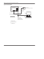
The programming device allows you to enter a ladder logic program into the micro
controller.
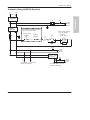
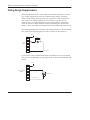
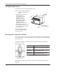
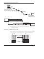
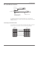
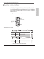
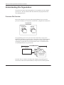
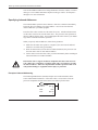
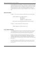
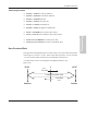
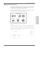
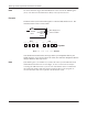
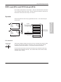
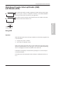
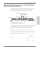
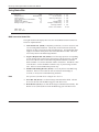
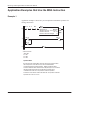
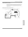
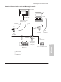
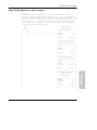
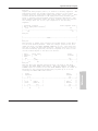
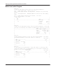
In the following illustration, the electromechanical circuit shows PB1 and PB2, two
pushbuttons, wired in series with an alarm horn. PB1 is a normally open
pushbutton, and PB2 is normally closed. This same circuit is shown in ladder logic
by two contacts wired in series with an output. Contact I/0 and I/1 are
examine-if-closed instructions.➀ (For more information on this instruction, refer to
page 6–4.)
PB1
Ladder Logic Program
Alarm
Horn
PB2
I
][
I
][
0
➀
O
( )
1
1
Contact I1 would be an examine-if-open instruction ( ]/[ ) if PB2 was a normally open electromechanical circuit.
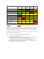
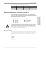
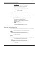
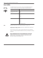
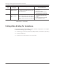
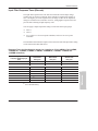
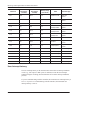
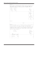
The table below shows how these circuits operate. The table shows all possible
conditions for the electromechanical circuit, the equivalent state of the ladder logic
instructions, and the resulting output state.
If PB1 is:
I/0 state is:
And PB2 is:
I/1 state is:
not pushed
0
not pushed
1
Then the Alarm Horn (O/1) is:
silent
not pushed
0
pushed
0
silent
pushed
1
not pushed
1
alarm
pushed
1
pushed
0
silent
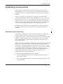
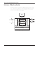
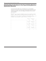
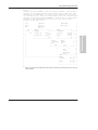
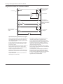
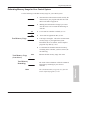
Developing Your Logic Program – A Model
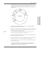
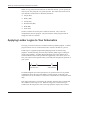
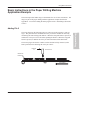
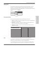
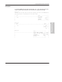
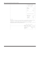
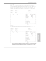
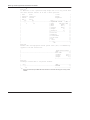
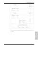
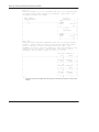
The following diagram can help you develop your application program. Each
process block represents one phase of program development. Use the checklist at
the right of the process block to help you identify the tasks involved with each
process.
4–15
Programming
Electromechanical Circuit