1
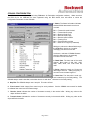
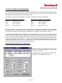
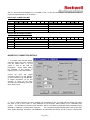
CONFIGURING THE DIP INC. CDN-066
FOR USE WITH AN ALLEN-BRADLEY 1747-SDN
APPLICATION NOTE
REVISION 01
DATE 8/01/2000
PURPOSE
This note is intended to provide information on programming and setup of the DIP Inc. CDN-066 DeviceNet –
ASCII Gateway module for use with an Allen-Bradley 1747-SDN DeviceNet scanner for the SLC-500 controller
family.
This note is not intended to replace the user manuals for either device, but instead is meant to extend the user
manual content.
It is assumed that the reader understands the basic operation of the CDN-066 and 1747-SDN and understands
basic DeviceNet principles.
INTENDED AUDIENCE
New users to the CDN-066 but users with some DeviceNet experience and SLC-500 programming experience.
This Application Note was tested with CDN-066 firmware 3.00.
FOR MORE INFORMATION
CDN-066
CDN-066 DeviceNet/Serial Gateway User Manual
http://www.dipinc.com/
1747-SDN
1747-SDN User Manual
Publication 1747-6.2.5
http://www.ab.com/manuals
ODVA Home Page
http://www.odva.org, Open DeviceNet Vendor Home Page.
ADDITIONAL MATERIALS
CDN-066 EDS File
Ladder Logic Prog.
http://www.dipinc.com/cgi-bin/product.exe?pid=CDN066
Page 1 of 1
CDN-066 CONFIGURATION
The CDN-066 is most easily configured using RSNetworx for DeviceNet configuration software. Make sure that
the EDS file for the CDN-066 has been registered using the EDS wizard, then edit offline or online the
configuration Parameters for the CDN-066.
1. Status: The Status information indicates
whether RS232 data transfer errors have
occurred.
Bit 0 = Transmit channel blocked
Bit 1 = Transmit buffer empty
Bit 2 = Receive Parity Error
Bit 3 = Receive buffer empty
Bit 4 = Receive buffer Overflow
Bit 5 = Framing Error
Bit 6 = Transmit buffer overflow
Bit 7 = State of CTS signal (1=asserted)
Writing any value to the Status field through
this RSNetworx window or via explicit
messaging will clear the error bits.
Versions 4.x and later of CDN066 firmware
allow the Status byte to be optionally
included in the I/O connection.
2. Baud Rate: The baud rate of the serial
channel. Baud rates of 300, 600, 1200,
2400, 4800, 9600, and 19.2k baud are
valid.
3. Parity: Setting the parity to 0 forces the
data length size to 8. Setting the parity to
non-zero forces the data length to 7.
4. Data Size: The data size is read only,
and is determine by the Parity setting. The
th
CDN066 always reads 8 data bits, but decides what to do with the 8 bit based on the Parity setting.
5. Stop Bits: The CDN066 always uses 1 stop bit. This value is fixed.
6. Flow Control: Serial channel flow control may be set by software. See the CDN066 user manual for details
on software flow control and CTS Detect usage.
7.
Receive Count: Indicates the number of characters currently in the receive buffer. Writing any value to this
object will flush the buffer.
8. Transmit Count: Indicates the number of characters currently in the transmit buffer. Writing any value to this
object will flush the buffer.
Page 2 of 2
9. Maximum Receive Size: This value indicates the maximum number of data bytes to be returned when the
receive buffer is read from DeviceNet.
Setting this value will automatically reset the Produced I/O Connection
Size as:
Input Connection Size =
Max Receive Size (maximum value 64 bytes)
+ 1 (If String format is enabled)
+ 1 (If Receive Sequential Numbering is enabled)
10. Data Format: The Data Format control byte determines the
type of data strings transferred via DeviceNet, which may either be
an array of bytes, or an ODVA-defined Short String data element,
which consists of a length byte followed by a specified number of
data bytes.
This control byte also determines if parity data is included in the
received data, and controls padding of empty DeviceNet input data
bytes if the Delimiter Character is received before the maximum
data length is reached.
Most ASCII text applications, such as barcode readers and weigh
scales, will use Short String mode and retain parity. Default is to
pad the responses with null characters and left-justify the data
strings.
See the CDN066 user manual for a full explanation of the Data
Format byte.
11. Block Mode: The Block Mode control byte determines how
the CDN066 handles delimiter characters and sequential
transmit/receive handshaking numbers.
Most ASCII text applications user the delimiter character but strip
the delimiter from the response packet.
Checking either one of the Sequence Numbers will automatically
Enable the Syncronous Handshaking protocol.
PLC applications always use the Re-Send Valid Data settings so
that repeated polls of the CDN066 will return the same input values
until a new string is received. It is important that the input data
arrive at the PLC for more than one poll because the PLC scan
and the DeviceNet interface scan are asynchronous.
12. Receive Delimiter: When Delimiter mode is enabled, the receipt of a specific byte will cause the Input
buffer to be returned in the DeviceNet Input I/O connection. Often this byte is ASCII Carriage Return (0x0D hex,
13 decimal).
If your ASCII device sends both a Carriage Return and a Line Feed at the end of ASCII strings, be sure to
use the Line Feed (0x0A hex, 10 decimal) as your Delimiter character. Otherwise, the LF will show up as the first
character of your next input string !
Page 3 of 3
13.
Pad Character: Used by the CDN066 to fill input data packets which are less than the Max Input Size in
bytes. Default is 13 decimal = 0x20 hex = SPACE. Enabling of padding and the selection of which side (left or
right) to justify the input string is determined by the Data Format byte.
14. Maximum Transmit Size: This value indicates the maximum number of data bytes to be transmitted when
the Output connection is received from DeviceNet. Setting this value will automatically reset the Consumed I/O
Connection Size as:
Output Connection Size = Max Transmit Size (maximum value 64 bytes)
+ 1 (If String format is enabled)
+ 1 (If Transmit Sequential Numbering is enabled)
Note that the Delimiter Character has no effect on the transmission of serial data from the CDN066. If a Carriage
Return or Line Feed or End of Text byte is needed in your application, it will need to be part of the data array
which is sent via the DeviceNet output I/O connection.
Page 4 of 4
1747-SDN CONNECTION AND MAPPING
In our example, the Polled I/O connection between the CDN-066 and the 1747-SDN will have a Produced (Input)
Data size equal to the Maximum Number of Input Characters plus two bytes, and a Consumed (Output) Data size
of the Maximum Number of Output Characters plus two bytes.
The default I/O connection for the CDN-066 is 18 bytes of Input Data, and 18 bytes of Output data.
INPUT DATA CONNECTION CONTENTS
Byte 0
Tx / Rx Handshaking Counters
Byte 1
Input Length Byte
Byte 2
ASCII Character 1
….
Byte 18
ASCII Character 16
OUTPUT DATA CONNECTION CONTENTS
Byte 0
Tx / Rx Handshaking Counters
Byte 1
Output Length Byte
Byte 2
ASCII Character 1
….
Byte 18
ASCII Character 16
Because the SLC-500 uses 16-bit I/O registers, it is sometimes programmatically awkward to have the ASCII data
array begin at Byte 1 (the eighth bit of the first mapped word). In RSNetworx for DeviceNet, Advanced Mapping
may be used to segment the I/O mapping of the Output Data to word-align the ASCII data in SLC memory.
In addition, Advanced Mapping may be employed to map the ASCII data bytes of the I/O connection to the M0
and M1 module files of the 1747-SDN. Because the 1747-SDN scanner has only 32 words of discrete I/O data, it
is often scarce, and less-frequently used data is often stored in the 150-word I/O memory of the module files. M0
and M1 files require COPY instructions to be executed to exchange their contents with the SLC-500 controller
memory (which requires some scan time).
Because the Receive Data Request handshaking counter will be
incremented in discrete memory when a new string comes in to the CDN-066, that change in value can trigger a
COPY instruction that brings the ASCII data into SLC-500 memory.
Example Data Map of CDN-066 in 1747-SDN memory
Because the input and output data maps are the
same size, this Advanced Mapping will be the same
for both Input and Output.
In applications with unequal Input and Output sizes,
adjust the Advanced Mapping accordingly.
Page 5 of 5
With the above Advanced Mapping to a 1747-SDN in Slot 1 of the SLC-500 chassis, SLC data areas where the
Input and Output data will go are as follows:
INPUT DATA CONNECTION MAP
I:1.1
M1:1.0
M1:1.1
…
M1:1.7
15
14
13
12
Receive Data Size
ASCII Character 2
ASCII Character 4
…
ASCII Character 16
11
10
09
08
07
06
05
04
Rx Request
ASCII Character 1
ASCII Character 3
…
ASCII Character 15
03
02
01
Tx Acknowledge
00
11
10
09
08
07
06
05
04
Rx Acknowledge
ASCII Character 1
ASCII Character 3
…
ASCII Character 15
03
02
01
Tx Request
00
OUTPUT DATA CONNECTION MAP
O:1.1
M0:1.0
M0:1.1
…
M0:1.7
15
14
13
12
Transmit Data Size
ASCII Character 2
ASCII Character 4
…
ASCII Character 16
IMPORTANT CONNECTION DETAILS
1. If the Max Input and Max Output
character sizes have been changed
from the default value of 16, be
certain to click on the “Edit I/O
Parameters”
button before adding
the CDN-066 to the scanlist or
mapping it to the 1747-SDN memory.
Correct the Input and Output
connection sizes to be the [Number
of Input Characters +2] and [Number
of Output Characters +2] for this
example, in which we are using
Synchronous Handshaking mode and
Short String format.
2. Once a polled connection has been mapped and downloaded to the 1747-SDN scanner module, be certain
that there is not an Error Code 77 being displayed on the module’s status display for the CDN-066’s node
number. This indicates a Connection Size mismatch, and the 1747-SDN is periodically sending messages to the
CDN-066 to establish a properly-sized connection.
This connection-request message traffic uses up the CDN066’s Explicit Message Connection, and RSNetworx for DeviceNet and RSLinx will not be able to communicate
Page 6 of 6
with the module until the 1747-SDN is removed from the network or the CDN-066’s scanlist entry is deleted or
deactivated.
3. If you have a properly sized I/O connection established between the 1747-SDN and the CDN-066 and attempt
to change the Input or Output character sizes, you will receive an “Error 0x12: Object State Conflict” message
from RSNetworx for DeviceNet.
Modifying either of these parameters changes the required connection size, and
therefore they cannot be changed while the connection is active. Remove the 1747-SDN from the network, or
delete or deactivate the CDN-066’s scanlist entry. Turning the processor into Program Mode or the 1747-SDN
into Idle mode does not break the connection and will not allow these parameters to be changed.
CDN-066 OPERATION
About the Transmit and Receive synchronous handshaking counters
The first byte of the Input and Output I/O connections consists of two 4-bit counters which are used for
handshaking.
To send data out of the RS232 serial port on the CDN066, the Transmit Request value is incremented by 1. The
CDN066 will send the serial data that arrived in that Output I/O poll, and respond by setting the Transmit
Acknowledge counter to the same value as the Transmit Request counter.
When the CDN066 received data in it’s RS232 serial port, it assembles that into an Input I/O poll response and
increments the Receive Request counter by 1. When the application program detects that the Receive Request
counter has incremented, it should copy the Input data into holding registers for storage, then set the Receive
Acknowledge counter to the same value as the Receive Request. The next string can then be sent over the I/O
connection by the CDN066.
Because these counters are 4 bits apiece, their roll over at the value 15, returning to 1. The value 0 is reserved
as an initial condition (for the Rx counter) and a reset value (for the Tx counter).
About the Status Byte
This byte indicates the status of any serial errors detected by the CDN-066. If this byte is included in the I/O
connection, it makes it easy to sense overflows and reset errors on the serial side of the CDN-066. Early
versions of the module (Firmware 3.x and previous) did not have the option to add this byte to the I/O connection,
though it is still available via explicit messaging.
Page 7 of 7
SLC-500 LADDER LOGIC EXAMPLE
This Application Note should be accompanied by an example RSLogix 500 program for the SLC-5/03
programmable controller, to read and write ASCII strings from a MicroScan MS-700 barcode reader via the CDN066.
Although ladder logic is flexible enough to allow many different approaches to data handling, the accompanying
program will have to include at least the following elements:
Enable the 1747-SDN
The first word of the discrete output image of the 1747-SDN is reserved for module commands. Bit 0 of this word
needs to be 1 for the 1747-SDN to send active polling commands. The 1747-SDN does poll for input data when
the scanner is idle, but it’s output polls have no content and are not processed by slave devices.
COPY ASCII data into memory when the Record Number changes
If the ASCII data bytes of the inputand output image have been mapped to the M1 file of the 1747-SDN, a COPY
instruction will be needed to retrieve them. Make sure that the SLC-500 has at least one scan to get that data into
memory before acting on it.
Perform handshaking logic
The simplest ladder program to enable serial input for testing would be to use just an MVM instruction to maskedmove the first word of the Input map to the first word of the Output map. More sophisticated handshaking logic is
usually necessary to send Output data upon a trigger, and to assure Input data is transferred efficiently out of
1747-SDN M-file memory into SLC memory.
Move ASCII data into a String data type
SLC-500 String data types are 42 words in length, with Word 0 designating the length in characters, and Words 1
through 41 being ASCII characters (up to 82 characters).
To move an array of Integer numbers into a String data element, a COPY command can be used. Reserve Word
0 for the string length, and be sure not to use any of the Integer values above your string length but below the 41word limit for other purposes in the program.
Fitting the example into your application
The program accompanying this application note is written for an SLC-5/05 processor with a 1747-SDN in Slot 1
of a 4-slot chassis, with no other I/O.
You will almost certainly have to perform search-and-replace functions to
fit the example logic into your application program.
The program is provided in RSLogix 500 version 4.10 format (*.RSS extension), as well as SLC-500 library format
(*.SLC extension) for import into other versions of the software.
Page 8 of 8