1
TECHNICAL
MANUAL
Control system for pellet stoves
REV. 2.0 - firmware 1.0
0
CONTENTS
1
CONTROL SYSTEM DESCRIPTION
6
6.1
2
CONTROL UNIT
DISPLAY MODULE
IR REMOTE CONTROLLER
2.1
2.2
2.3
6.2
TECHNICAL FEATURES
6.2.1
6.2.2
7
7
8
6.2.3
6.3
6.3.1
6.3.2
6.3.2.1
3
6.3.2.2
INSTALLATION
6.3.2.3
6.3.3
CONTROL UNIT FASTENING
DISPLAY MODULE FASTENING
WIRING
3.1
3.2
3.3
9
6.3.4
10
6.3.5
12
6.3.5.1
6.3.5.2
6.3.6
4
6.3.6.1
PARAMETERS
6.3.7
6.3.8
USER PARAMETERS
TECHNICAL PARAMETERS
4.1
4.2
14
6.4
16
6.5
6.5.1
6.5.2
6.5.3
5
ALARMS AND WARNINGS LIST
6.6
5.1
ALARMS
38
5.2
WARNINGS
46
7
7.1
7.1.1
7.1.2
7.1.3
FUNCTIONAL DESCRIPTION
TURNING ON
TURNING ON CONDITIONS
Turning On with "Cold" stove
Turning On with "Warm" stove
Stove management after Blackout event
WORKING
Comfort
Thermoregulation
Thermoregulation with NTC10KΩ Ambient Temperature Probe
Thermoregulation with Ambient Thermostat
ECO function
Too High Smoke Temperature Event
Automatic Cleaning
Chrono Mode
Weekly Programming
Trip Mode Function
Use of the Delta P Sensor
Abnormal Event detected by the Delta P Sensor
Ambient Fan
Pellet Level Sensor
TURNING OFF
FUNCTIONS
Antifreeze
Manual Cleaning
Dehumidification
IR REMOTE CONTROLLER
48
48
48
51
52
53
53
54
55
56
57
57
58
58
59
60
61
61
62
62
64
65
65
65
66
66
CONTROL UNIT HARDWARE
TYPE A USB 2.0 PORT
Parameters and Event Log Download
Parameters Upload to Control Unit
Control Unit Software Update
67
67
68
69
0
CONTENTS
SAFETY FUSE
EMI FILTER
HIGH VOLTAGE OUTPUT FEEDBACK
RECHARGEABLE BACKUP BATTERY
DOUBLE INSULATION
7.2
7.3
7.4
7.5
7.6
71
9
73
73
73
74
9.1
9.1.1
8
9.1.2
HYDRO CONFIGURATION
9.2
9.3
8.1
8.2
8.2.1
8.2.2
8.3
8.4
8.4.1
8.4.2
8.5
8.5.1
8.5.2
8.5.3
8.6
8.6.1
8.7
8.7.1
8.7.2
8.7.3
8.7.4
8.7.5
8.7.6
8.7.7
8.7.8
ON BOARD EXPANSION FEATURES
FASTENING AND WIRING
Fastening
Wiring
SPECIFIC TECHNICAL PARAMETERS FOR HYDRO CONFIGURATION
ALARMS AND WARNINGS WITH HYDRO CONFIGURATION
Alarms
Warnings
OPERATIONAL MODES WITH HYDRO CONFIGURATION
Comfort
Ambient Regulation
Water Regulation
ADDED FUNCTIONS WITH HYDRO CONFIGURATION
Water Pump Anti - Lock Function
MANAGED HYDRAULIC CONFIGURATIONS
Configuration 1
Configuration 2
Configuration 3
Configuration 4
Configuration 5
Configuration 6
Configuration 7
Configuration 8
DUCTED AIR CONFIGURATION
9.3.1
75
76
76
77
78
82
82
83
85
85
85
86
86
86
86
86
89
92
95
98
101
104
107
9.3.2
9.4
9.4.1
9.4.2
9.4.3
9.4.4
WIRING
Single Ducted Air
Double Ducted Air
SPECIFIC TECHNICAL PARAMETERS FOR DUCTED AIR CONFIGURATION
ALARMS AND WARNINGS FOR DUCTED AIR CONFIGURATION
Alarms
Warnings
FUNCTIONALITY WITH DUCTED AIR CONFIGURATION
Ducted Ambient Fan management
Thermoregulation management
Thermoregulation with Single Ducted Air Configuration
Thermoregulation with Double Ducted Air Configuration
110
110
111
112
116
116
117
118
118
118
120
122
1
CONTROL SYSTEM DESCRIPTION
The RICA control system for pellet stoves is made up of a set of electronic devices, which allow you to manage
different types of pellet stoves (simple air, ducted air, and hydro).
2
TECHNICAL FEATURES
2.1 CONTROL UNIT
In particular, this system allows you to check pellet stove components in order to:
Supply Voltage 230 Vac ± 10%, 50Hz
ELECTRICAL FEATURES
Efficiently manage the combustion process
Maximum Power 500W
Detect and handle any malfunctions
ENVIRONMENTAL
FEATURES
The main system components are:
•
Control Unit
Insulation Class Class II with SELV Secondary Circuit
•
Working Temperature 0..55°C
Humidity 0..85% RH without condensation
DIMENSIONS
Display (LCD)
B X H X S 112 X 178 X 45mm
2 X Motor Encoders (Hall Sensor)/Auxiliary Inputs (free
Insulated contacts)
3 X NTC Probes (3X10KΩ or 2 X10KΩ + 1X100KΩ)
1 X Thermocouple (J or K)
1 X Motor Encoder (Hall Sensor)
2 X Safety Switches (normally closed)
4 X TRIAC 1.2A (Smoke Motor, Ambient Fan, Ignition
Heater, Auger) with safety relay to disconnect the loads
Insulated
3X Output with Voltage supply = 5V ±10%
(Max current = 20mA)
Battery
On Board Backup
On Board Expansion
INPUT
OUTPUT
Turn & Push
EXPANSIONS
On Bus Differential pressure sensor
Type A USB (Firmware / Parameters Update, Parameters /
Event Log Download)
COMMUNICATION
•
IR (Infrared) Remote Controller
2.2 DISPLAY MODULE
DISPLAY TYPE
ELECTRICAL FEATURES
DIMENSIONS
CASE
MATERIAL
WORKING TEMPERATURE RANGE
Graphic LCD
Supply Voltage 12Vdc ± 10%
B X H X S 167 X 52 X 30mm
Base PC ABS
Mask PMMA
-10...70°C
7 USER MANUAL
2
TECHNICAL FEATURES
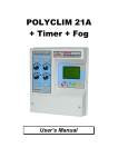
2.3 IR REMOTE CONTROLLER
3
INSTALLATION
3.1 CONTROL UNIT FASTENING
Fasten the Control Unit to the plaque provided in the pellet stove using the six M3 nylon spacers and twelve M3 nylon
ELECTRICAL
FEATURES
ENVIRONMENTAL
FEATURES
DIMENSIONS
(AAA) Alkaline Batteries
Supply Voltage 224LR03
months life (average)
screws (supplied with the Control Unit), as shown in the image below.
Working Temperature 0...50°C
Humidity 0…85% RH without condensation
B X H X S 120 X 52 X 29mm
MAX TRANSMISSION DISTANCE 4m
TRANSMISSION TYPE Unidirectional IR (with beep feedback)
9 USER MANUAL
3
3
INSTALLATION
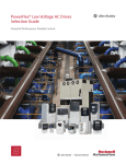
3.2 DISPLAY MODULE FASTENING
In order to secure the Display Module in the compartment provided in the pellet stove, carry out the following
Ensure that the LIN cable is attached to the frame as shown in the figure below:
steps:
Make sure the Display Module is disconnected from the Control Unit
Open the plastic case of the Display Module (made up of frame and cover) by unscrewing the four screws with
a screwdriver as shown in the figure below:
Close the Display Module with its cover by tightening the four screws and making sure to pass the LIN cable
through the slot provided, as shown in the figure below:
Cover
Frame
Slot for threading Lin
cable
Insert the plastic frame (holding the electronic board) into the compartment provided in the pellet stove
11 USER MANUAL
3
INSTALLATION
3.3Wiring
Part 1
Part 2
Smoke Motor
Ambient Fan
Safety Air Pressure
Switch
Smoke Motor Encoder
Ignition Heater
(normally closed contact)
Δp
Encoder
Neutral
Heart
+
Phase
-
NC
Auger
Safety Bulb Thermostat
(normally closed contact)
°C
NO
segnale
Delta P
cable
Delta P
Power supply
3 – poles LIN cable
Display Module
-
+
-
+
Smoke Thermocouple
AMB
α
Sonda NTC10KΩ
NTC10KΩ
AmbientAmbiente
Temperatura
Temperature Probe
13 USER MANUAL
4
PARAMETERS
4.1 User Parameters
MENU
LEVEL
SUB
LEVEL 1
SUB
LEVEL 2
TURN ON/OFF
MODE
VALUES
"TURN ON" is shown when the stove is switched off, and
"TURN OFF" when the stove is switched on. Command to
turn on or turn off the stove
YES/NO
Allows you to set the stove to Manual or Chrono (Weekly
Programming) operational mode
MANUAL/CHRONO
MENU
LEVEL
SUB
LEVEL 1
SUB
LEVEL 2
DESCRIPTION
VALUES
-
DATE/HOUR
Allows the user to set the system date and time
ANTIFREEZE
Allows you to enable or disable the antifreeze function.
With this function enabled, when the stove is turned off
and the temperature read by the Ambient Probe is 1°C
lower than the "ANTIFREEZE" technical parameter value
(CONFIGURATION sub-menu), the stove is turned on at
Comfort level 3, until the ambient temperature exceeds the
"ANTIFREEZE" value (CONFIGURATION sub-menu) by 5°C
ON/OFF
OFF-1-15-OFF
REGULATION
Allows you to set the stove to Comfort Regulation or
Thermoregulation
COMFORT/
TEMPERATURE
TRIP MODE
When this function is enabled (value other than OFF),
and the stove is in Chrono mode at the same time, the
stove remains turned off (even if the weekly Programme
was due to turn it on) for the set number of days,
starting from the following day
ECO FUNCTION
Allows you to enable "Eco" function during
Thermoregulation, setting the stove to Turn Off if the
room is warm, and back on when it is cold
ON/OFF
AMBIENT FAN
Allows you to manually set the Ambient Fan speed, from
a choice of 5 levels, or to automatically regulate the
speed according to Comfort level
LEVEL 1...5 /
AUTO
DUCTED FAN 1
Allows you to manually set the speed of the Ducted
Ambient Fan 1, from a choice of 5 levels, or to
automatically regulate the speed according to Comfort
level, or to disable the Ducted Ambient Fan 1. Displayed
only for Single or Double Ducted stove
LEVEL 1...5 /
AUTO/OFF
DUCTED FAN 2
Allows you to manually set the speed of the Ducted
Ambient Fan 2, from a choice of 5 levels, or to
automatically regulate the speed according to Comfort
level, or to disable the Ducted Ambient Fan 2. Displayed
only for Double Ducted stove
LEVEL 1...5 /
AUTO/OFF
COPY
PROGRAM
DESCRIPTION
Sunday...Saturday
COPY
CLEANING ON/OFF
Copies Chrono Program from one day to another
-
Sets the Weekly Programme for every day of the
week from Sunday to Saturday, with a 30 minute
resolution (every 30 minutes, you can set a Comfort or
Temperature value, depending on whether the stove is
set to Comfort or Temperature regulation)
-
Copies Chrono Program from one day to another
-
Command to activate manual cleaning mode. During this
phase the Smoke Motor is switched to maximum speed
for a given time, unless deactivation is carried out in
manual mode. Not displayed when the stove is turned on
TOOLS
BEEP
YES/NO
LANGUAGE
Enables/disables the beep for setting of parameters
Sets menu items language
ON/OFF
ITALIANO/
ENGLISH/...
HEAT OF
COMBUS.: LOW,
NORMAL, HIGH
PELLET
TYPE
Allows setup of characteristics of the pellet which is being
used: the calorific value ("HEAT OF COMBUS.") and the
length ("LENGTH"), which can be configured through the
menu "SERVICE" ("CONFIGURATION" > "PELLET TYPE")
DUCTED
SET 1
Set Point Ambient Air temperature in room
thermoregulated by Ducted Ambient Fan 1. Parameter
displayed only for Single or Dual Ducted stove
15-35°C
DUCTED
SET 2
Set Point Ambient Air temperature in room
thermoregulated by Ducted Ambient Fan 2. Parameter
displayed only for Dual Ducted stove
15-35°C
SETTINGS
Water Set Point temperature. Parameter
WATER SET Radiators
displayed only for Water Regulation with hydro stove
SERVICE
Menu containing technical parameters, accessed by
Service or OEM (with two different passwords)
LENGTH:
SHORT,
MEDIUM, LONG
45-70°C
--
15 USER MANUAL
4
PARAMETERS
4.2 TECHNICAL PARAMETERS
LOGIN
MAIN MENU
LEVEL 1
LEVEL 2
STRING
DESCRIPTION
RANGE
RES.
UNIT
Smoke % Variation
Percentage change in Smoke Motor aspiration speed (all phases)
± 10
1
%
Auger OFF
Auger pause time during Working phase in Comfort 1
0-25
0.1
s
Auger ON
Auger working time during Working phase in Comfort 1
0-25
0.1
s
Auger OFF
Auger pause time during Working phase in Comfort 2
0-25
0.1
s
Auger ON
Auger working time during Working phase in Comfort 2
0-25
0.1
s
Auger OFF
Auger pause time during Working phase in Comfort 3
0-25
0.1
s
Auger ON
Auger working time during Working phase in Comfort 3
0-25
0.1
s
Auger OFF
Auger pause time during Working phase in Comfort 4
0-25
0.1
s
Auger ON
Auger working time during Working phase in Comfort 4
0-25
0.1
s
Auger OFF
Auger pause time during Working phase in Comfort 5
0-25
0.1
s
Auger ON
Auger working time during Working phase in Comfort 5
0-25
0.1
s
Ignition Heater continuous operation test, Duration = 10s. "Ignition Heater Test" is displayed during the test
NO/YES
--
--
Auger continuous operation test, Duration = 10s. "Auger Test" is displayed during the test
NO/YES
--
--
AUX RELAY
Relay closure test on On Board Expansion: Duration = 10s. "AUX RELAY
Test" is displayed during the test
NO/YES
--
--
AUX TRIAC
Triac continuous operation test on On Board Expansion: Duration = 10s.
"AUX TRIAC Test" is displayed during the test
NO/YES
--
--
COMFORT 1
COMFORT 2
TECHNICIAN
COMFORT 3
COMFORT 4
SERVICE/OEM
COMFORT 5
IGNITION HEATER
AUGER
TEST
17 USER MANUAL
4
PARAMETERS
LOGIN
MAIN MENU
LEVEL 1
COMFORT 1
LEVEL 2
STRING
TEST
COMFORT 3
COMFORT 5
UNIT
NO/YES
--
--
Ambient Fan
Ambient Fan in Comfort 1 test, Duration = 10s. "Fan Test" is displayed
during the test
NO/YES
--
--
Auger in Comfort 1 test, Duration = 1 minute during which multiple
cycles take place. "Auger Cycle 1 min" is displayed during the test
NO/YES
--
--
Smoke Motor
Smoke Motor in Comfort 2 test, Duration = 1min. "Smoke Motor Test"
is displayed during the test
NO/YES
--
--
Ambient Fan
Ambient Fan in Comfort 2 test, Duration = 10s. "Fan Test" is displayed
during the test
NO/YES
--
--
Auger in Comfort 2 test, Duration = 1 minute during which multiple
cycles take place. "Auger Cycle 1 min" is displayed during the test
NO/YES
--
--
Smoke Motor
Smoke Motor in Comfort 3 test, Duration = 1 min. "Smoke Motor Test"
is displayed during the test
NO/YES
--
--
Ambient Fan
Ambient Fan in Comfort 3 test, Duration = 10s. "Fan Test" is displayed
during the test
NO/YES
--
--
Auger in Comfort 3 test, Duration = 1 minute during which multiple
cycles take place. "Auger Cycle 1 min" is displayed during the test
NO/YES
--
--
Smoke Motor
Smoke motor in Comfort 4 test, Duration = 1 min. "Smoke Motor Test"
is displayed during the test
NO/YES
--
--
Ambient Fan
Ambient Fan in Comfort 4 test, Duration = 10s. "Fan Test" is displayed
during the test
NO/YES
--
--
Auger Cycle
(1min)
Auger in Comfort 4 test, Duration = 1 minute during which multiple
cycles take place. "Auger Cycle 1 min" is displayed during the test
NO/YES
--
--
Smoke Motor
Smoke Motor in Comfort 5 test, Duration = 1 min. "Smoke Motor Test"
is displayed during the test
NO/YES
--
--
Ambient Fan
Ambient Fan in Comfort 5 test, Duration = 10s. "Fan Test" is displayed
during the test
NO/YES
--
--
Auger Cycle
(1min)
Auger in Comfort 5 test, Duration = 1 minute during which multiple
cycles take place. "Auger Cycle 1 min" is displayed during the test
NO/YES
--
--
Auger Cycle (1 min)
COMFORT 4
RES.
Smoke Motor in Comfort 1 test, Duration = 1 min. "Smoke Motor Test"
is displayed during the test
Auger Cycle (1min)
SERVICE/OEM
RANGE
Smoke Motor
Auger Cycle (1min)
COMFORT 2
DESCRIPTION
19 USER MANUAL
4
PARAMETERS
LOGIN
MAIN MENU
TEST
LEVEL 1
LEVEL 2
STRING
RES.
UNIT
Forces turn off, regardless of phase (unless an alarm is in progress
or the stove is already turned off)
NO/YES
--
--
TURN ON
Forces turn on, regardless of phase (unless an alarm is in progress
or the stove is already turned on)
NO/YES
--
--
Fw Version
Displays the Firmware version of the Control Unit and any satellites
connected to it (e.g. LCD display)
--
--
--
Aux Input
Displays temperature/state of NTC inputs and IN AUX related to the
On Board Expansion
--
--
--
Displays TC, NTC1, NTC2, NTC3 sensors temperature/state
--
--
--
Analog Input
Displays Analogue Input value
--
--
--
Digital Input
Displays IN1 and IN2 Digital Inputs state
--
--
--
Smoke Motor rpm
--
--
--
Ambient Fan
Displays Ambient Fan % power
--
--
--
Output Check
Displays power Out feedback state (OUT5: Out Triac On Board Expansion)
--
--
--
Alarm Input
Displays High Voltage AL1 and AL2 Alarm Inputs
--
--
--
Diff. Press.
Displays differential pressure of the inward flow at the air intake
of the stove (in mPa)
--
--
--
Displays Comfort or Temperature Set Point level set
--
--
--
Current Comfort
Displays Comfort level in use in the stove
--
--
--
Curr. State/Mode
Displays current phase and regulation (Comfort or Temperature)
--
--
--
FORCING
Rpm Smoke Motor
DIAGNOSTIC
RANGE
TURN OFF
Probes
SERVICE/OEM
DESCRIPTION
Set Point
21 USER MANUAL
4
PARAMETERS
LOGIN
MAIN MENU
LEVEL 1
LEVEL 2
STRING
RANGE
RES.
UNIT
YES/NO
--
--
Displays total hours electrical power supply to the stove
--
--
hours
Displays total hours working time of the stove
--
--
hours
LAST SERVICE
Displays working phase hours since last service reset
--
--
hours
SERVICE RESET
Reset last service hours Counter
YES/NO
--
--
SERVICE CYCLE
Sets the duration (in hours) before service request (Warning display)
100-10000
100
hours
Allows matching to the couple of parameters "HEAT OF COMBUS." and
"LENGTH" (found in the user menu under "PELLET TYPE"), the variation
(in %) of the Auger motor working time and the Smoke Motor speed.
--
--
--
No Ambient Temperature Probe inserted
--
--
--
Ambient Temperature Probe type NTC10KΩ used
--
--
--
External Thermostat used as Ambient Temperature Probe
--
--
--
Air stove configuration
--
--
--
Single Ducted
Single Ducted Air stove configuration
--
--
--
Double Ducted
Double Ducted Air stove configuration
--
--
--
Hydro
Hydro stove configuration
--
--
--
NONE
No sensor selected
RESET
DESCRIPTION
Restore factory settings
POWER SUPPLY
SERVICE/OEM
WORKING
COUNTERS
OEM
PELLET TYPE
NONE
SERVICE/OEM
AMBIENT PROBE
NTC10K
THERMOSTAT
Air
CONFIGURATION
OEM
SERVICE/OEM
STOVE TYPE
AIR SENS. TYPE
DELTA P
Differential pressure sensor selected, DELTA P menu can be displayed
23 USER MANUAL
4
PARAMETERS
LOGIN
MAIN MENU
LEVEL 1
LEVEL 2
STRING
Altitude
Diff. Press. Hyst.
DESCRIPTION
RANGE
RES.
UNIT
Altitude of the area in which the stove is installed
0-3000
1
m
Hysteresis to add up (or subtract) to the level of the Differential Pressure
Set point set up to obtain the upper (or lower) limit of the optimal range.
0-500
10
mPa
Diff. Press. C1
Differential Pressure Set Point in Comfort 1
0-20000
10
mPa
Diff. Press. C2
Differential Pressure Set Point in Comfort 2
0-20000
10
mPa
Diff. Press. C3
Differential Pressure Set Point in Comfort 3
0-20000
10
mPa
Diff. Press. C4
Differential Pressure Set Point in Comfort 4
0-20000
10
mPa
Diff. Press.C5
Differential Pressure Set Point in Comfort 5
0-20000
10
mPa
Differential Pressure level below which the warning message is shown
on the display. If the differential pressure is below half of this value the
system switches to alert mode.
0-5000
10
mPa
DELTA P
CONFIGURATION
Warn. Diff. Press.
SMOKE PROBE
OEM
TC J TYPE
Type J Thermocouple used (connected to TC input)
--
--
--
TC K TYPE
Type K Thermocouple used (connected to TC input)
--
--
--
NTC100K
NTC100KΩ used (connected to NTC1 input)
--
--
--
Auto menu exit timeout if not used (User access)
2-30
1
min
SERVICE
Auto menu exit timeout if not used (Service access)
2-180
1
min
PIN VIEW
Displays Service PIN
--
--
--
Change pin for Service Menu access
--
--
--
Displays OEM pin
--
--
--
Change pin for OEM Menu access
--
--
--
USER
TIMEOUT MENU
SERVICE/OEM
SERVICE PIN
PIN
OEM
OEM PIN
PIN CHANGE
PIN VIEW
PIN CHANGE
25 USER MANUAL
4
PARAMETERS
LOGIN
MAIN MENU
LEVEL 1
LEVEL 2
STRING
RANGE
RES.
UNIT
ON/OFF
--
--
1-600
1
min
ON/OFF
--
--
Offset value read from TC Smoke Probe
± 10
1
°C
NTC1 Offset
Offset value read from NTC1 Probe
± 10
1
°C
NTC2 Offset
Offset value read from NTC2 Probe
± 10
1
°C
NTC3 Offset
Offset value read from NTC3 Probe
± 10
1
°C
NTC Aux Offset
Offset value read from NTC Probe connected to On Board Expansion
± 10
1
°C
ANTIFREEZE
Minimum ambient temperature limit for Antifreeze function activation
5-15
1
°C
Present
PELLET SENSE
Remaining Time
Auto Turn Off
SERVICE/OEM
CONFIGURATION
TC Offset
DESCRIPTION
Set to ON when pellet sensor present
Indicates remaining operational minutes of the stove at maximum power,
when the Pellet Level Sensor (which must be connected to the Control
Unit IN2 input) detects a low pellet level.
If the stove is not working at full power the remaining number of minutes
is taken from this parameter according to the current Comfort level
When set to "ON", automatic turn off of the stove is activated shortly
before the pellet tray is emptied
PROBES OFFSET
SERVICE/OEM
27 USER MANUAL
4
PARAMETERS
LOGIN
MAIN MENU
SERVICE/OEM
LEVEL 1
LEVEL 2
STRING
EVENTS LIST
DESCRIPTION
Show stored events log, most recent first
RANGE
RES.
UNIT
--
--
--
YES/NO
--
--
600-3000
60
rpm
0-120
5
s
EVENTS LOG
DELETE
Clears events list
Smoke Motor
Duration
Smoke Motor aspiration speed during Initial Cleaning phase
Initial Cleaning phase duration
INIT. CLEANING
Ignit. Heater
Ignition Heater activation during Initial Cleaning phase
ON/OFF
--
--
Interruption
Allows user to turn off the stove during Initial Cleaning phase
ON/OFF
--
--
0-120
5
s
ON/OFF
--
--
600-3000
60
rpm
0-250
10
s
Duration
Stove Heating phase duration
STOVE HEATING
OEM
Interruption
Allows user to turn off the stove during Stove Heating phase
PROCESS
Smoke Motor
Smoke Motor aspiration speed during Initial Load phase
Auger Load
Pellet loading duration (Auger in continuous operation) during Initial
Load phase
Ignit. Heater
Ignition Heater activation during Initial Load phase
ON/OFF
--
--
Interruptible
User is able to switch off the stove in the Initial Loading phase
ON/OFF
--
--
Smoke Motor
Smoke Motor aspiration speed during Waiting Flame phase
600-3000
60
rpm
0-25
0.1
s
INITIAL LOAD
FLAME WAITING
Auger OFF
Auger pause time during Waiting Flame phase
29 USER MANUAL
4
PARAMETERS
LOGIN
MAIN MENU
LEVEL 1
FLAME WAITING
LEVEL 2
STRING
0.1
s
Duration
Waiting Flame phase duration
0-600
5
s
ON/OFF
--
--
600-3000
60
rpm
Allows user to turn off the stove during Waiting Flame phase
Smoke Motor
Smoke Motor aspiration speed during Turn On phase
Ambient Fan
Ambient Fan speed during Turn On phase
0-100%
1
%
Ignit. Heater
Ignition Heater use during Turn On phase
ON/OFF
--
--
Auger OFF
Auger pause time during Turn On phase
0-25
0.1
s
Auger ON
Auger working time during Turn On phase
0-25
0.1
s
Minimum smoke Temperature increase above which the stove is
considered turned on compared with the reference level at the end
of Waiting Flame phase
0-120
1
°C
Turn On phase maximum duration
1-20
1
min
ON/OFF
--
--
600-3100
60
rpm
Interruption
STABILIZATION
UNIT
0-25
Max Time
PROCESS
RES.
Auger working time during Waiting Flame phase
Flame On Delta
OEM
RANGE
Auger ON
Interruption
LIGHTING ON
DESCRIPTION
Allows user to turn off the stove during Turn On phase
Smoke Motor
Smoke Motor aspiration speed during Stabilization phase
Ambient Fan
Ambient Fan speed during Stabilization phase
0-100%
1
%
Ignit. Heater
Ignition Heater activation during Stabilization phase
ON/OFF
--
--
Auger OFF
Auger pause time during Stabilization phase
0-25
0.1
s
Auger ON
Auger working time during Stabilization phase
0-25
0.1
s
Temperature increase per minute during Stabilization phase.
If increase is not reached the system activates the "ABNORMAL TURN
ON" alarm
0-25
1
°C/min
Stabilization phase duration
0-4
1
min
ON/OFF
--
--
Stabiliz. Rate
Duration
Interruption
Allows user to turn off the stove during Stabilization phase
31 USER MANUAL
4
PARAMETERS
LOGIN
MAIN MENU
LEVEL 1
LEVEL 2
COMFORT 1
OEM
PROCESS
WORKING
COMFORT 2
COMFORT 3
STRING
DESCRIPTION
RANGE
RES.
UNIT
Smoke Motor
Smoke Motor aspiration speed during Comfort 1 phase
600-3000
60
rpm
Ambient Fan
Ambient Fan Percentage Power during Comfort 1 phase
0-100
1
%
Smoke temperature threshold, above which the Ambient Fan is activated
at comfort 1, if the fan is in AUTO mode (below this threshold, the fan is
switched off)
10-350
1
°C
AmbFanTempThrs
Auger OFF
Auger pause time during Working phase Comfort 1
0-25
0.1
s
Auger ON
Auger working time during working phase Comfort 1
0-25
0.1
s
Smoke Motor
Smoke Motor aspiration speed during working phase Comfort 2
600-3000
60
rpm
Ambient Fan
Ambient Fan Percentage Power during working phase comfort 2
0-100
1
%
Smoke temperature threshold, above which the Ambient Fan is activated
at Comfort 2, if the fan is in AUTO mode
10-350
1
°C
AmbFanTempThrs
Auger OFF
Auger pause time during working phase Comfort 2
0-25
0.1
s
Auger ON
Auger working time during working phase Comfort 2
0-25
0.1
s
600-3000
60
rpm
Smoke Motor
Smoke Motor aspiration speed during Comfort 3 phase
Ambient Fan
Ambient Fan Percentage Power during working phase Comfort 3
0-100
1
%
Smoke temperature threshold, above which the ambient fan is activated
at Comfort 3, if the fan is in AUTO mode
10-350
1
°C
AmbFanTempThrs
Auger OFF
Auger pause time during Working phase Comfort 3
0-25
0.1
s
Auger ON
Auger working time during working phase Comfort 3
0-25
0.1
s
33 USER MANUAL
4
PARAMETERS
LOGIN
MAIN MENU
LEVEL 1
LEVEL 2
COMFORT 4
OEM
PROCESS
WORKING
COMFORT 5
THERMOREGUL.
STRING
DESCRIPTION
RANGE
RES.
UNIT
Smoke Motor
Smoke Motor aspiration speed during Comfort 4 phase
600-3000
10
rpm
Ambient Fan
Ambient Fan Percentage Power during Comfort 4 phase
0-100
1
%
Smoke temperature threshold, above which the Ambient Fan is activated
at Comfort 4, if the fan is in AUTO mode
10-350
1
°C
AmbFanTempThrs
Auger OFF
Auger pause time during working phase Comfort 4
0-25
0.1
s
Auger ON
Auger working time during working phase Comfort 4
0-25
0.1
s
600-3000
60
rpm
Smoke Motor
Smoke Motor aspiration speed during Comfort 5 phase
Ambient Fan
Ambient Fan Percentage Power during working phase Comfort 5
0-100
1
%
Smoke temperature threshold, above which the Ambient Fan is activated
at Comfort 5, if the fan is in AUTO mode
10-350
1
°C
AmbFanTempThrs
Auger OFF
Auger pause time during Working phase Comfort 5
0-25
0.1
s
Auger ON
Auger working time during working phase Comfort 5
0-25
0.1
s
Comfort Boost
Comfort value used on starting stove until it reaches Set Point + Sup
Differential
1-5
--
--
Inf Differential
Value to subtract from Set Point temperature to reach temperature limit
below which Comfort is set to "Maximum Comfort"
0,1-5
0.1
°C
Max Comfort
Heating comfort in relation to Inf Differential
1-5
--
--
0,1-5
0.1
°C
1-5
--
--
Sup Differential
Min Comfort
Value to add to Set Point temperature to reach temperature limit above
which Comfort is set to "Minimum Comfort"
Maintenance comfort in relation to Sup Differential
35 USER MANUAL
4
PARAMETERS
LOGIN
MAIN MENU
LEVEL 1
LEVEL 2
WORKING
AUTOM.CLEAN.
STRING
Period
Duration
OEM
RANGE
RES.
UNIT
Interval between Brazier Cleaning phases
0-180
1
min
Brazier Cleaning duration
10-240
5
s
600-3000
10
rpm
Smoke Motor
Smoke Motor aspiration speed during Turn Off phase
Ambient Fan
Ambient Fan Percentage Power during controlled Turn Off phase (System
in Alarm)
0-100
1
%
Smoke temperature threshold below which stove is considered
turned off, during Turn Off phase or in alarm during Working phase
("ABNORMAL FLAME OFF")
10-120
1
°C
Smoke Temperat.
LIGHTING OFF
DESCRIPTION
Duration
Minimum Turn Off phase duration (when the smoke temperature is above
the value set in "Temp. Safety Temp")
0-30
1
min
Safety Temp.
Temperature threshold above which the manual cleaning procedure is
activated, but scrolling Warning message "HIGH SMOKE TEMPERATURE"
is activated. During Turn On phase, if the smoke temperature exceeds
this value, Turn Off phase will have a minimum duration (as set in the
"Duration" parameter in the same menu)
10-120
1
°C
Smoke Motor Rel.
Smoke Motor aspiration speed in Stove Heating, Initial Load and Waiting
Flame phases when the stove is turned on during a "warm" stove
relighting event.
600-3000
60
rpm
Smoke Temp. Rel.
Smoke temperature threshold below which stove is considered turned
off during a "warm" stove relighting event
10-120
1
°C
Smoke Temp. Max
Maximum smoke temperature, above which the "TOO HIGH SMOKE
TEMPERATURE" warning is activated
100-350
1
°C
BlackOut Time
Minimum time to keep the stove in Working phase after a Black Out
1-240
1
s
Ability to exclude Dehumidification function
ON/OFF
--
--
Allows user to stop Dehumidification, passing directly to ignition using
a long push of the display knob
ON/OFF
--
--
PROCESS
RELIGHTING
ALARMS
Enable
DEHUMIDIFICAT.
Interruption
LEGEND:
OEM
Menu accessible only by OEM with specific password
SERVICE/OEM
Menu accessible by OEM or Service with two different passwords
37 USER MANUAL
5
ALARMS AND WARNINGS LIST
5.1ALARMS
SHOWN ON DISPLAY (SCROLLING) "FLAME NOT PRESENT"
During Turn On phase the smoke temperature must not
by a value equal to "Flame On Delta" (LIGHTING ON
ABNORMAL DESCRIPTION increase
submenu) within a time equal to "Max Time" (LIGHTING ON
submenu)
During the Alarm phase: Ignition Heater OFF, Auger OFF,
Motor to maximum speed, until stove cold (smoke
ACTIONS TAKEN Smoke
temperature below threshold of "Smoke Temperat." in
LIGHTING OFF submenu)
USER RESET Display knob depressed for 5s
DISPLAY SAVED TO EVENTS LOG "NO FLAME"
(INTERNAL MEMORY)
SHOWN ON DISPLAY (SCROLLING) "ABNORMAL FLAME OFF"
In working phase the smoke temperature falls below
ABNORMAL DESCRIPTION the alarm threshold (Smoke Temperat." in LIGHTING
OFF submenu)
During the Alarm phase: Ignition Heater OFF, Auger
Smoke Motor to maximum speed, until stove cold
ACTIONS TAKEN OFF,
(smoke temperature below "Smoke Temperat." threshold
in LIGHTING OFF submenu)
USER RESET Display knob depressed for 5s
DISPLAY SAVED TO EVENTS LOG "FLAME OFF KO"
(INTERNAL MEMORY)
SHOWN ON DISPLAY (SCROLLING) "ABNORMAL LIGHTING"
In the Stabilization phase, smoke temperature does not inABNORMAL DESCRIPTION crease or increases with a rate lower than the value set in the
"Stabiliz. Rate" parameter in the STABILIZATION submenu
During the Alarm phase: Ignition Heater OFF, Auger OFF,
Motor to maximum speed, until stove cold (smoke
ACTIONS TAKEN Smoke
temperature below threshold of "Smoke Temperat." in
LIGHTING OFF submenu)
USER RESET Display knob depressed for 5s
DISPLAY SAVED TO EVENTS LOG "ABNORM. FIRING"
(INTERNAL MEMORY)
SHOWN ON DISPLAY (SCROLLING) "STOVE OVERHEATING"
ABNORMAL DESCRIPTION Bulb thermostat tripped (open contact)
During the Alarm phase: Ignition Heater OFF, Auger OFF,
Motor to maximum speed, until stove cold (smoke
ACTIONS TAKEN Smoke
temperature below threshold of "Smoke Temperat." in
LIGHTING OFF submenu)
USER RESET Bulb Thermostat manual reset
DISPLAY SAVED TO EVENTS LOG "STOVE OVERHEATING"
(INTERNAL MEMORY)
39 USER MANUAL
5
ALARMS AND WARNINGS LIST
SHOWN ON DISPLAY (SCROLLING) "TOO HIGH SMOKE TEMPERATURE"
Smoke temperature above maximum temperature ("Smoke
Max", in the ALARMS submenu) and timeout expired
ABNORMAL DESCRIPTION Temp.
(timeout duration displays "HIGH SMOKE TEMPERATURE",
see warnings list)
During the Alarm phase: Ignition Heater OFF, Auger OFF,
Motor to maximum speed, until stove cold (smoke
ACTIONS TAKEN Smoke
temperature below threshold of "Smoke Temperat." in
LIGHTING OFF submenu)
USER RESET Display knob depressed for 5s
SHOWN ON DISPLAY (SCROLLING) "SMOKE MOTOR KO"
ABNORMAL DESCRIPTION Damaged Smoke Motor Output (delayed alarm)
ACTIONS TAKEN During the Alarm phase: Ignition heater OFF, Auger OFF
USER RESET Display knob depressed for 5s
DISPLAY SAVED TO EVENTS LOG "SMOKE OUT DAMAGED"
(INTERNAL MEMORY)
DISPLAY SAVED TO EVENTS LOG "SMOKE T HIGH"
(INTERNAL MEMORY)
SHOWN ON DISPLAY (SCROLLING) "OBSTRUCTED CHIMNEY"
ABNORMAL DESCRIPTION Air Pressure Switch tripped (open contact)
During the Alarm phase: Ignition Heater OFF, Auger OFF,
Motor to maximum speed, until stove cold (smoke
ACTIONS TAKEN Smoke
temperature below threshold of "Smoke Temperat." in
LIGHTING OFF submenu)
USER RESET Display knob depressed for 5s
DISPLAY SAVED TO EVENTS LOG "CHIMNEY OBSTR."
(INTERNAL MEMORY)
SHOWN ON DISPLAY (SCROLLING) "SMOKE MOTOR KO"
ABNORMAL DESCRIPTION Smoke Motor blocked (delayed alarm)
ACTIONS TAKEN During the Alarm phase: Ignition heater OFF, Auger OFF
USER RESET Display knob depressed for 5s
DISPLAY SAVED TO EVENTS LOG "SMOKE M BLOCKED"
(INTERNAL MEMORY)
41 USER MANUAL
5
ALARMS AND WARNINGS LIST
SHOWN ON DISPLAY (SCROLLING) "SMOKE MOTOR KO"
ABNORMAL DESCRIPTION Smoke Motor phases disconnected (delayed alarm)
ACTIONS TAKEN During the Alarm phase: Ignition heater OFF, Auger OFF
USER RESET Display knob depressed for 5s
DISPLAY SAVED TO EVENTS LOG
(INTERNAL MEMORY) "SMOKE M DISC."
SHOWN ON DISPLAY (SCROLLING) "AMBIENT FAN KO"
Fan phases disconnected or Ambient Fan output damaged
ABNORMAL DESCRIPTION Ambient
(delayed alarm)
During the Alarm phase: Ignition Heater OFF, Auger OFF, Smoke
ACTIONS TAKEN Motor to maximum speed, until stove cold (smoke temperature
below threshold of "Smoke Temperat." in LIGHTING OFF submenu)
USER RESET Display knob depressed for 5s
DISPLAY SAVED TO EVENTS LOG "AIR MOTOR KO"
(INTERNAL MEMORY)
SHOWN ON DISPLAY (SCROLLING) "IGNITION HEATER KO"
Heater disconnected or Ignition Heater output
ABNORMAL DESCRIPTION Ignition
damaged (delayed alarm)
During the Alarm phase: Ignition Heater OFF, Auger OFF,
Motor to maximum speed, until stove cold (smoke
ACTIONS TAKEN Smoke
temperature below threshold of "Smoke Temperat." in
LIGHTING OFF submenu)
USER RESET Display knob depressed for 5s
DISPLAY SAVED TO EVENTS LOG "IGNIT. HEAT. KO"
(INTERNAL MEMORY)
SHOWN ON DISPLAY (SCROLLING) "AUGER KO"
phases disconnected or Auger damaged
ABNORMAL DESCRIPTION Auger
(delayed alarm)
ACTIONS TAKEN All loads are disconnected (Safety Relay open)
USER RESET Display knob depressed for 5s
DISPLAY SAVED TO EVENTS LOG "AUGER KO"
(INTERNAL MEMORY)
SHOWN ON DISPLAY (SCROLLING) SMOKE PROBE KO
ABNORMAL DESCRIPTION Smoke Probe fault in Working phase
the Alarm phase: Smoke Motor OFF, Ambient Fan OFF,
ACTIONS TAKEN During
Ignition Heater OFF, Auger OFF
USER RESET Display knob depressed for 5s
DISPLAY SAVED TO EVENTS LOG "SMOKE PROBE KO"
(INTERNAL MEMORY)
SHOWN ON DISPLAY (SCROLLING) "ELECTRONIC BOARD KO"
ABNORMAL DESCRIPTION Communication loss to Control Unit internal bus
ACTIONS TAKEN All loads are disconnected (Safety Relay open)
USER RESET Display knob depressed for 5s
DISPLAY SAVED TO EVENTS LOG "ELECTRONIC KO"
(INTERNAL MEMORY)
43 USER MANUAL
5
ALARMS AND WARNINGS LIST
SHOWN ON DISPLAY (SCROLLING) "POWER BLACKOUT: WAIT STOVE COOLING"
SHOWN ON DISPLAY (SCROLLING) "AIR FLOW LACKING"
Pressure read by the sensor below half of value
ABNORMAL DESCRIPTION Differential
set in "Warn. Diff. Press." parameter
ABNORMAL DESCRIPTION Electrical network loss with stove on
During the Alarm phase: Ignition Heater OFF, Auger OFF,
Motor to maximum speed, until stove cold (smoke
ACTIONS TAKEN Smoke
temperature below threshold of "Smoke Temperat." in
LIGHTING OFF submenu)
If when the mains power supply returns the smoke
temperature exceeds the threshold "Smoke Temperat. in the
LIGHTING OFF submenu and the power loss duration is less
than the parameter BlackOut Time in the ALARMS submenu,
the stove will stay in the last phase before the Black Out.
ACTIONS TAKEN Otherwise, the system performs a controlled shutdown of
the stove (Ignition Heater and Auger OFF, Smoke Motor to
maximum) until the stove is cold. Once the stove is cold (and
the minimum time set in "Duration" in the LIGHTING OFF
submenu has expired), the message "POWER BLACKOUT EMPTY BRAZIER" appears
USER RESET Display knob depressed for 5s
DISPLAY SAVED TO EVENTS LOG "NO AIR FLOW"
(INTERNAL MEMORY)
USER RESET Display knob depressed for 5s
DISPLAY SAVED TO EVENTS LOG "NO POWER SUPPLY"
(INTERNAL MEMORY)
SHOWN ON DISPLAY (SCROLLING) "ELECTRONIC BOARD OVERHEATING"
Unit temperature greater than safety threshold
ABNORMAL DESCRIPTION Control
(non-configurable value)
During the Alarm phase: Ignition Heater OFF, Auger OFF,
Motor to maximum speed, until stove cold (smoke
ACTIONS TAKEN Smoke
temperature below threshold of "Smoke Temperat." in
LIGHTING OFF submenu)
USER RESET Display knob depressed for 5s
DISPLAY SAVED TO EVENTS LOG "T ELECTRONIC HI"
(INTERNAL MEMORY)
For all:
INTERMITTENT BEEP ALARM YES
45 USER MANUAL
5
ALARMS AND WARNINGS LIST
5.2WARNINGS
SHOWN ON DISPLAY (SCROLLING) "HIGH SMOKE TEMPERATURE"
ABNORMAL DESCRIPTION Smoke temperature above threshold ("Smoke Temp. Max")
ACTIONS TAKEN Comfort automatically set to minimum
USER RESET Display knob short depress
DISPLAY SAVED TO EVENTS LOG --(INTERNAL MEMORY)
SHOWN ON DISPLAY (SCROLLING) "DELTA P SENSOR KO"
configured with Delta P Sensor present but the sensor
ABNORMAL DESCRIPTION Stove
is not communicating with the Control Unit
ACTIONS TAKEN System automatically configured without Delta P Sensor
USER RESET Display knob short depress
DISPLAY SAVED TO EVENTS LOG "DELTA P KO"
(INTERNAL MEMORY)
SHOWN ON DISPLAY (SCROLLING) "AMBIENT PROBE KO"
ABNORMAL DESCRIPTION Ambient Temperature Probe faulty or disconnected
enabled, Thermoregulation or Antifreeze functions
ACTIONS TAKEN If
are automatically disabled
USER RESET Display knob short depress
DISPLAY SAVED TO EVENTS LOG "AIR PROBE KO"
(INTERNAL MEMORY)
SHOWN ON DISPLAY (SCROLLING) "OBSTRUCTED BRAZIER
Pressure read by the sensor below the value set
ABNORMAL DESCRIPTION Differential
in "Pres.Diff.Warn." parameter
Motor at maximum speed (set in the "Smoke Motor"
ACTIONS TAKEN Smoke
parameter in the "LIGHTING OFF" submenu)
USER RESET Display knob short depress
DISPLAY SAVED TO EVENTS LOG BRAZIER OBSTR."
(INTERNAL MEMORY)
SHOWN ON DISPLAY (SCROLLING) "SERVICE REQUEST"
When you provide power supply the system notices that
ABNORMAL DESCRIPTION the stove working hours number is larger than SERVICE
LIFECYCLE parameter value in the COUNTERS submenu
ACTIONS TAKEN --USER RESET Display knob short depress
DISPLAY SAVED TO EVENTS LOG "SERVICE" REQUEST."
(INTERNAL MEMORY)
SHOWN ON DISPLAY (SCROLLING) "REMAINING TIME <NUMBER OF MINUTES>"
If Present parameter in the PELLET SENS. is set to ON and
is connected to a Pellet Level Sensor on IN2 on the Control
ABNORMAL DESCRIPTION Unit, this warning is activated when the sensor detects a
low pellet level. <number of minutes> shows the remaining
operational minutes for the stove and updates automatically
ACTIONS TAKEN ---
SHOWN ON DISPLAY (SCROLLING) "THERMOSTAT ON NTC 2 OUT OF RANGE"
ABNORMAL DESCRIPTION Thermostat voltage supply in intake NTC2 out of range
USER RESET Display knob short depress
DISPLAY SAVED TO EVENTS LOG --(INTERNAL MEMORY)
Mode automatically set and Antifreeze (if already
ACTIONS TAKEN Comfort
enabled) is disabled
USER RESET Display knob short depress
DISPLAY SAVED TO EVENTS LOG OUT TH NTC2 KO
(INTERNAL MEMORY)
47 USER MANUAL
6
FUNCTIONAL DESCRIPTION
6.1 TURNING ON
Once secured, wired and powered correctly, in order to start the Turn On phase of the stove you must enter the USER
MENU by pushing the display knob and positioning the cursor on the first entry "TURN ON".
It is then necessary to push the knob again, and select "YES" and depress the display knob once more.
Alternatively, you may turn on with a long push (5s) of the display knob.
This will start the Turn On phase in the system, which is accompanied by an audible notification (beep) and the
scrolling display shows "TURN ON IN PROGRESS - PLEASE WAIT".
2. STOVE HEATING:
Phase during which the Ignition Heater only has been activated to heat the brazier before entering the Initial
Load phase.
The parameters for this phase are in the submenu "STOVE OVERHEATING"
3. INITIAL LOAD:
Phase during which the Auger has also been continuously enabled, in order to preload the Brazier with an initial
layer of pellets before entering the Flame Waiting phase.
The parameters for this phase are in the "INITIAL LOAD" submenu
4. FLAME WAITING:
Phase during which the Smoke Motor and Ignition Heater only are activated, in order to speed up the
combustion process in the following phase.
6.2 TURNING ON CONDITIONS
The parameters for this phase are in the "WAITING FLAME" submenu
5. LIGHTING ON:
The system allows two turn on conditions:
Phase in which the Smoke Motor, the Auger and the Ignition Heater are active, in order to aid combustion
initiation and the consequent flame presence. This phase completes when the difference between the smoke
•
Turning on with stove "cold" (stove is in OFF state, or the minimum smoke temperature detected is lower than the
temperature at the beginning of this phase, and the current smoke temperature, exceeds the threshold set in
value set in the parameter "Smoke Temperat." in the submenu LIGHTING OFF and the stove can be considered
parameter "Flame On Delta" in submenu LIGHTING ON. If this threshold is not exceeded within a time equal to
cold)
the value set in the parameter "Max Time" in the LIGHTING ON submenu, the system goes into Alarm state, with
the scrolling display message "FLAME NOT PRESENT". When the smoke temperature exceeds the threshold set
•
Turning on with stove "warm" (user relights stove, setting the parameter "TURN ON" to "YES", when the Turn Off
in the parameter "AmbFanTempThrs" in the COMFORT 1 submenu, the Ambient Fan is also activated.
phase is in progress in the stove)
The parameters for this phase are in the "LIGHTING ON" submenu
6. STABILIZATION:
6.2.1 Turning on with "Cold" stove
This stage consists of the following subphases in turn:
1. INIT. CLEANING:
Phase during which the Smoke Motor (to carry out initial cleaning of the Brazier) and the Ignition Heater are
Temporal phase for flame stabilization, in which the Ignition Heater is disabled whilst the Smoke Motor and
Auger remain enabled. During this phase the smoke temperature increase is monitored every minute. If this
increase at a rate lower than the value set in the parameter "Stabiliz. Rate" in the STABILIZATION submenu, the
system goes into the alarm "ABNORMAL LIGHTING".
When the smoke temperature exceeds the threshold set in the parameter "AmbFanTempThrs" in the COMFORT
1 submenu, the Ambient Fan is also activated.
The parameters for this phase are in the submenu STABILIZATION"
activated. The Ignition Heater can be disabled by selecting "OFF " in the parameter "Ignit. Heater" in the INIT.
CLEANING submenu.
All the parameters for this phase are in the "INIT. CLEANING" submenu
49 USER MANUAL
6
FUNCTIONAL DESCRIPTION
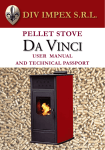
6.2.2 Turning On with "Warm" stove
Turning on with stove "warm" takes place when the stove is turned on again (see para. 6.1) when it is in Lighting
Off phase. In this case the Lighting Off phase completes when the smoke temperature is below the value set
in the parameter "Smoke Temp. Rel." in the RELIGHTING submenu and a given time has expired (parameter
"Duration" in LIGHTING OFF submenu). Once the Lighting Off phase is complete, the system repeats all phases
for Turn On with stove "cold" (see para. 6.2.1), with the difference that during the phases "Stove Heating", "Initial
Load" and "Waiting Flame" phases the smoke motor is activated at the speed set in the parameter "Smoke Motor
Rel." in the RELIGHTING submenu.
Parameter Smoke Temp. Max" (Alarms submenu)
Parameter Smoke Temp. Max" (Alarms submenu)
Parameter "AmbFanTempThrs" (Comfort 1 submenu)
SMOKE TEMPERATURE
°C
SMOKE TEMPERATURE
Parameter AmbFanTempThrs" (Comfort 1 submenu)v
°C
PARAMETER "FLAME ON DELTA" (SUBMENU’ LIGHTING ON)
PARAMETER "FLAME ON DELTA" (SUBMENU’ LIGHTING ON)
Parameter Smoke Temp. Rel" (RELIGHTING submenu)
ON
ON
AUGER
AUGER
OFF
OFF
ON
ON
IGNITION HEATER
IGNITION HEATER
OFF
OFF
ON
ON
Ambient Fan
Ambient Fan
OFF
OFF
ON
ON
SMOKE MOTOR
Parameter "Smoke Motor"
(LIGHTING OFF submenu)
Smoke Motor
OFF
Parameter Smoke Motor Rel.."
(RELIGHTING submenu)
OFF
TEMPORAL PHASE TEMPORAL PHASE TEMPORAL PHASE TEMPORAL PHASE
OFF
INIT.
CLEANING
TURN ON COMMAND
STOVE
HEATING
INITIAL
LOAD
waiting
flame
TEMPORAL PHASE
LIGHTING ON
STABILIZATION
C1
C2
C3
C4
WORKING
C5
TEMPORAL
PHASE
LIGHTING OFF
INIT.
CLEANING
TEMPORAL
PHASE
STOVE
HEATING
TEMPORAL PHASE
INITIAL
LOAD
TEMPORAL
PHASE
WAITING
FLAME
TEMPORAL PHASE
LIGHTING ON
STABILIZATION
C1
C2
C3
C4
C5
WORKING
TURN ON COMMAND
51 USER MANUAL
6
FUNCTIONAL DESCRIPTION
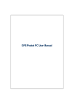
6.2.3 Stove management after Blackout event
6.3WORKING
(PHASE AVAILABLE ONLY WITH BATTERY INSERTED)
The system allows you to manage the stove with the following two regulation modes:
Should an electrical power blackout occur when the stove is not switched off (stove OFF), when the power supply
•
Comfort
system is reconnected, the system will read the smoke temperature and time of the electrical network failure (blackout
•
Thermoregulation
time). If the smoke temperature is greater than the parameter "Smoke Temperat." in the LIGHTING OFF submenu
(or the stove is still warm) and the power loss duration is less than the parameter "BlackOut Time" in the ALARMS
submenu, the system will stay in the last phase it was in before the power failure.
In the event however that the stove is still warm, but the power loss duration is greater than the "BlackOut Time" (or
the flame is no longer present in the brazier) the stove will enter the controlled turn off state, activating the Smoke
Motor at maximum and shows the scrolling display "POWER BLACKOUT: WAIT STOVE COOLING".
This state persists until the stove becomes cold (or the smoke temperature falls below the threshold set in the
parameter "Smoke Temperat." in submenu LIGHTING OFF and a minimum interval has passed, which is equal to
"Duration" in submenu LIGHTING OFF), following which the display shows the message "POWER BLACKOUT: EMPTY
6.3.1 Comfort
To select Comfort mode, you must access the User Menu, menu item "REGULATION" and select "COMFORT".
In this mode the stove is set to fixed power regardless of the ambient temperature. In this way, the system ensures
constant Comfort, maintaining the speeds of the Smoke Motor and Ambient Fan at a given value, as well as the duty
cycle of the Auger.
Five Comfort levels are available, which can be selected as follows:
BRAZIER".
Time
Comfort level
POWER ON
“No power supply: Empty brazier”
wait for User Reset
YES
COLD
STOVE?
NO
LAST
OFF
STATE?
YES
Turn & Push
STATO
LAVORO
OFF state
Ambient temperature
(if Ambient Temperature
Probe is present)
NO
Turn&Push Knob
Comfort Originale + Reset
T FUMI
• Scritta
GoWarning
to theseIDLE
menu in the display
(see above Figure)
presente
NO
SLOW
BLACK
OUT?
NO
YES
“Last” State
ELEVATA?
•
Depress the display knob: the last bar begins to flash, and you may change the Comfort level
•
Change Comfort level by turning theSI display knob
•
Select the level chosen by pushing the display knob once more (the final bar stops flashing and a confirmation
beep is generated). If no new Comfort level is selected, after 10s the previous level is restored and the bar stops
Controlled Stove Turn Off
+
“Power Blackout: Wait Stove
Cooling”
blinking.
TIMEOUT
SCADUTO?
SI
Stato Allarme
+
Scritta Allarme
NO
Minimo
NB: When in this state, ifComfort
you wish
to access the User Menu, you must depress the knob twice
+
NO
Sritta Warning
COLD
STOVE?
YES
NO
You can set the relative parameters (Smoke Motor speed, Ambient Fan speed, and Auger duty cycle) for each
Comfort level in the submenus COMFORT 1-5 (OEM level).
SI
53 USER MANUAL
6
FUNCTIONAL DESCRIPTION
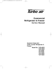
6.3.2 Thermoregulation
6.3.2.1 Thermoregulation with NTC10KΩ Ambient Temperature Probe
To select Thermoregulation mode, you must access the User Menu, menu item "REGULATION" and select "TEMPE-
In this mode, the stove power is modulated in such a way as to maintain the ambient temperature around the Set
RATURE".
Point temperature. You may set this range in the THERMOREGUL. submenu under the following menu items:
Thermoregulation must be managed in two distinct modes, according to the value set in the parameter
•
"AMBIENT PROBE" in the submenu CONFIGURATION:
"Sup Differential" : Offset to be added to Set Point temperature to find the upper limit above which the Comfort
level stored in the "Min Comfort" parameter will be set.
•
•
NTC10K: in this case an NTC10KΩ temperature sensor must be connected to input NTC2 and the stove will modulate the power according to the temperature read by the Ambient Temperature Probe
•
"Inf Differential" : Offset to be subtracted from Set Point temperature to find the lower limit, below which the
THERMOSTAT: in this case an ambient temperature thermostat must be connected to input NTC2 on the Control
Comfort level stored in the "Max Comfort" or "Comfort Boost" (in the event that Working phase has just been reached)
Unit and the stove will modulate the power according to the thermostat state.
parameters will be set
The following shows the correct configuration of the thermostat wiring in the Control Unit
Sup Differential"
(Thermoregul. submenu)
AMBIENT TEMPERATURE
°C
"Inf Differential"
(Thermoregul. submenu)
Ambient Temperature Set Point
ON
AUGER
OFF
AMBIENT FAN
°T
Ambient
thermostat
NB:
SMOKE MOTOR
"Comfort Boost"
(THERMOREGUL. SUBMENU)
"Min Comfort"
(THERMOREGUL.
SUBMENU)
"Max Comfort"
(THERMOREGUL.
SUBMENU)
The Ambient Thermostat must be wired in such a way that the contact closes when the ambient temperature
falls below the temperature threshold set
55 USER MANUAL
6
FUNCTIONAL DESCRIPTION
Once the stove is in Working phase, you may change the Temperature Set Point as follows:
6.3.2.3 ECO Function
•
Setting parameter "ECO FUNCTION" in the User Menu to "ON" thermoregulation will be managed in "ECO"mode: when
Go to the IDLE menu in the display (see below Figure)
the ambient temperature exceeds the upper temperature limit the stove will be turned off, while when it falls below
the lower limit, it will be turned on at the Comfort level stored in "Max Comfort".
Thermoregulation is managed in "ECO" mode, also where an Ambient Thermostat is used in place of the Ambient
Temperature Probe NTC10KΩ.
Thermoregulation Activated Icon
6.3.3 Too High Smoke Temperature Event
If during the working state the temperature read by the smoke probe exceeds the value set in the parameter
"Smoke Temp. Max" in the ALARMS submenu, the system will automatically activate the minimum comfort level
(submenu COMFORT 1) and at the same time display the warning message "HIGH SMOKE TEMPERATURE".
If the smoke temperature falls below the alarm threshold again, then the previous comfort level will automatically
Set Point Temperature
be restored, and the warning message will be deactivated. If instead the smoke overtemperature condition persists
for over 5 minutes, the system will move in to Alarm state, displaying the warning message "TOO HIGH SMOKE
POWER ON
TEMPERATURE".
• Depress the display knob: the Set Point temperature begins to flash, and you may change the value
WORKING
STATE
• Change the Set Point temperature,
by turning the display know (the Set Point temperature
resolution is 0.5°C)
“Mancanza Rete: Svuotare Braciere”
ULTIMO
NO
SI
SI
STUFA
FREDDA?
e attesa Reset Utente
STATO
OFF?
Stato OFF
• Select the Set Point by pushing the display knob once more (the Set Point temperature stops flashing). If no
NO
new Set Point level is selected, after 10s the previous entry is restored
and the temperature stops blinking.
BLACK OUT
LUNGO?
NO
Stato “Accensione”
(Accensione “a caldo”)
Set Comfort +
Warning Message Reset
(if present)
NO
HIGH
SMOKE
TEMP?
YES
SI
6.3.2.2. Thermoregulation with Ambient Thermostat
Spegnimento Controllato
+
“Mancanza
Rete: NTC10KΩ, with the variation that
Operation is similar to Thermoregulation with Ambient Temperature
Probe
Spegnimento in corso”
the power levels modulation is carried out according to the ON/OFF state of the ambient thermostat.
In this mode, in the display IDLE state, the display will show a string
indicating the thermostat state.
NO
STUFA
FREDDA?
SI
TIMEOUT
EXPIRED?
YES
Alarm State
+
Alarm Message
NO
Min Comfort
+
Warning Message
NO
SI
57 USER MANUAL
6
FUNCTIONAL DESCRIPTION
6.3.4 Automatic Cleaning
6.3.5.1 Weekly Programming
During Working phase, the stove can be set to periodically carry out automatic brazier cleaning. In this state the
To carry out weekly programming, please refer to the following sequence:
Smoke Motor turns at maximum speed (corresponding to value set in the parameter "Smoke Motor" in the "LIGHTING
OFF" submenu).
Access the menu "PROGRAM"
The duration and interval of automatic cleaning can be set using the "Duration" and "Interval" parameters respectively,
in the submenu AUTOM. CLEANING.
Browse through the days of the week by turning the knob on the display to select the required day
Access the day of the week by depressing the knob
6.3.5 Chrono Mode
Place the cursor on the initial programming time, by rotating the knob and selecting by depressing
The system can be set to Chrono mode, in which you may program the stove weekly, in order that it turns on and
off at certain times, with a certain Comfort level (or Set Point Temperature, when in Thermoregulation). In particular,
Place the cursor on the end programming time, by rotating the knob and selecting by depressing.
for each day of the week, you can programme the stove with a minimum time range equal to 30 minutes. To select
After doing so a flashing bar will be shown on the display, which highlights the time interval selected
Chrono mode, you must access the User Menu, menu item "MODE" and select "CHRONO".
Refer to the images below for some examples of Chrono mode operation.
Choose the desired Comfort level (or Temperature Set Point, if in Thermoregulation) by turning the knob and
selecting it by pushing. If in Thermoregulation using an Ambient Thermostat, select whether or not to turn on
the stove (ON o OFF) by turning the knob and selecting the action by pushing.
Next Turn ON Time
Program Start/Stop time
Turn & Push
Chrono Mode Icon
Set Time range
Set Comfort Level
Next Turn OFF Time
Turn & Push
Turn & Push
Current Comfort Level
Day
Temperature Set Point
59 USER MANUAL
6
FUNCTIONAL DESCRIPTION
You may repeat the above steps to set multiple program intervals, within the same day
Exit the program for the selected day by turning the knob until the message "BACK" appears, in the place of the
Comfort level (or Set Point Temperature) and depress
If required it is possible to repeater the above operations with a different day of the week, or copy the day program
just set, to another day. To carry out the latter, you must:
• Turn the display knob until the message "COPY" is shown, and depress
• Place the cursor on the day containing the program to be copied, by rotating the knob and selecting by
depressing
• Place the cursor on the day to which the program chosen in the previous step is to be copied, by rotating
the knob and selecting by depressing
• You can repeat the above steps to make further copies
• To exit the copy procedure, turn the display knob until the message "BACK" is shown, and then depress
6.3.6 Use of the Delta P Sensor
During the Working state, the system can make use of the Differential pressure sensor Sensirion model SDP610 to measure the differential pressure of the combustion air detected by the sensor at two points of the air
intake of the stove (in which a difference in pressure should be created in the combustible air) and as a result
regulate the Smoke Motor speed automatically, so as to maintain differential pressure of the combustion air
around the Set Point value set. This allows the combustion process efficiency to be maximised. To connect the
sensor correctly to the board use the appropriate cable as shown in par. 3.3 (Part 2). Please refer to the sensor
documentation with regards to the method of installing the differential pressure sensor Sensiron SDP-610 on
the stove and with regards to the related technical characteristics.
In order to activate the Differential Pressure Sensor (Delta P), you must:
Access submenu AIR SENS. TYPE (accessible to both Service and OEM) and select DELTA P parameter. Once you select
such parameter, the DELTA P submenu will be displayed in the next position under the AIR SENS. TYPE submenu.
In the submenu DELTA P Setting the parameter "Altitude" with the altitude value of the area in which the stove is
placed (range 0-3000m)
Set the range within which the differential pressure of the combustive air may vary, without affecting the Smoke
Motor speed (parameter "Diff. Press. Hyst.")
6.3.5.2 Trip Mode Function
When the system is in Chrono mode, you can activate the function "Trip Mode" by accessing the parameter "TRIP
MODE" and setting the number of days' absence from the home.
If, for example, the function is activated, at 00:00 of the following day, the stove turns off (if on) or remains
OFF for a number of days equal to the value set in the parameter "TRIP MODE" (even if, according to the weekly
Set the level of differential pressure of the combustive air to be maintained during each Comfort level, so as to
maximize combustion efficiency for each level (parameter "Diff. Press.C1-C5")
Set the level of the differential pressure of the combustive air, below which an anomaly is detected during
Working state (e.g. pipe obstructed) using the parameter "Warn. Diff. Press."
programming, the stove should turn on).
6.3.6.1 Abnormal Events detected by the Delta P Sensor
String indicating Trip Mode Function is enabled
In the Working state, if the differential pressure of the combustive air falls below the value set in parameter
"Warn. Diff. Press.", the display will show the warning message "OBSTRUCTED BRAZIER". If instead the
differential pressure of the combustive air falls below half the value set in "Warn. Diff. Press. , the system will
then enter the Alarm state, and the display will show the message: "AIR FLOW LACKING"
NB:
For more detailed information regarding the Sensirion sensor SDP-610 please consult the relevant
documentation.
61 USER MANUAL
6
FUNCTIONAL DESCRIPTION
6.3.7 Ambient Fan
The Ambient Fan speed can be managed in two ways:
When the Pellet Level Sensor is active, and the system is in the Working phase, at the moment in which the
sensor detects that the pellet level is low, the display will show (along with an audible beep) the warning
Fixed speed regardless of Comfort level, if the parameter "AMBIENT FAN" in the User Menu is set to LEVEL 1...5
message "REMAINING TIME <number of minutes>", where <number of minutes> indicates the remaining
number of operational minutes of the stove, and which is automatically decremented until the value 0 is reached.
Speed automatically linked to Comfort level set, where "AMBIENT FAN" in the User Menu is set to AUTO
If the parameter "Auto Turn Off" is set to "ON" shortly before the pellet tray empties, the stove is turned off
automatically.
6.3.8 Pellet Level Sensor
Setting parameter "Present" in the submenu SENS. PELLET to "ON" a Pellet Level Sensor can be managed, if
available. The image below illustrates the correct connection of the Pellet Level Sensor to the Control Unit.
Out 0V
Digital
Sensor
+5V
Pellet
-V
Out
+V
Pellet Level Sensor
Pellet level sensor must be of a digital type, with a 5V±10% power supply (max consumption = 20mA),
NB: The
and with a digital output normally in the high state (5V) and which can be put into low state (0V) when the
sensor detects a low Pellet level
63 USER MANUAL
6
FUNCTIONAL DESCRIPTION
6.4 TURNING OFF
If the stove is in the working state, and you wish to turn it off, it is necessary to access the User Menu, and select the first
menu item "TURN OFF". It is then necessary to push the knob again, and select menu item "YES" and depress the display
knob once more. Alternatively, you may enter the Turn Off phase with a long push (5s) of the display knob. This will start
the Turn Off phase in the system, which is accompanied by an audible notification (beep) and the scrolling display shows
"SYSTEM TURNING OFF - WAIT"
During this phase, the Smoke Motor is activated to ensure progressive smoke temperature reduction, while the Ambient
Fan speed progressively reduces according to the smoke temperature reduction, until it falls below the threshold set in
the parameter "AmbFanTempThrs" in the COMFORT 1 submenu. When the stove is turned off (smoke temperature below
the value set in parameter "Smoke Temperat." in the LIGHTING OFF submenu) and a given time period has passed (which
can be set using the "Duration" parameter in the LIGHTING OFF submenu) the system moves to the OFF state (in which
the Smoke Motor is also deactivated) and the scrolling display is also cleared.
If the stove is already "cold" (smoke temperature below the value set in parameter "Safety Temp" in the LIGHTING
OFF submenu) the system passes immediately to the OFF state. The parameters for this phase are in the submenu
"LIGHTING OFF".
6.5FUNCTIONS
6.5.1 Antifreeze
To activate this function, an NTC10KΩ probe must be connected to input NTC2 on the Control Unit, the parameter
"AMBIENT PROBE" set to "NTC10K" and finally, access the ANTIFREEZE menu item (User Menu) and select "ON".
When the function "Antifreeze" is active, if the stove is off and an ambient temperature value below 1°C in relation
to the value set in the parameter "ANTIFREEZE" (in CONFIGURATION submenu) is read, then the stove will turn on
automatically at Comfort level 3 and during the Turn On phase, on the display will be shown the message "SYSTEM
TURNING ON - ANTIFREEZE".
When the Antifreeze function activates, the following screen is shown on the display:
String indicating Antifreeze function is activated
Parameter "Smoke Temp. Max" (submenu Alarms)
SMOKE TEMPERATURE
Parameter "AmbFanTempThrs" (submenu COMFORT 1)
°C
Parameter "Smoke Temperat. (submenu LIGHTING OFF)
AUGER
ON
OFF
When the ambient temperature is exceeds the value set in parameter "ANTIFREEZE" (in CONFIGURATION submenu) by
5°C, the stove turns of automatically, displaying the message "SYSTEM TURNING OFF - ANTIFREEZE".
IGNITION HEATER
Ambient Fan
ON
OFF
6.5.2 Manual Cleaning
ON
To activate this function, you must access the menu CLEANING ON (available only when the stove is turned off)
and select "YES".
OFF
When the Manual Cleaning function is active the Smoke Motor turns at maximum (the value is set in parameter
"Smoke Motor" in submenu LIGHTING OFF ) for 10 minutes, and the display shows the message "CLEANING IN
Smoke Motor
PROGRESS". The function can be stopped manually by pressing the knob to enter CLEANING OFF in the menu and
ON
selecting "YES’".
Minimum Duration (Parameter "Duration"
in Lighting Off menu)
OFF
C1
C2
C3
C4
When this function is activated, and the smoke temperature is greater than the value set in parameter "Safety Temp"
(in LIGHTING OFF submenu), the display will show the warning message "HIGH SMOKE TEMPERATURE".
C5
WORKING
TURNING OFF
OFF
TURN OFF COMMAND
65 USER MANUAL
6
7
FUNCTIONAL DESCRIPTION
CONTROL UNIT HARDWARE
6.5.3 Dehumidification
7.1 TYPE A USB 2.0 PORT
The function "Dehumidification" is available when the Ignition Heater is managed with Triac (Ignition Heater connected
A type A USB 2.0 port is present on the Control Unit, as illustrated in the image below:
to OUT3 on the Control Unit).
To activate this function, you must access the submenu DEHUMIDIFICAT, select the parameter "Enable" and select
"ON". If the function "Dehumidification" is active when the stove is turned on, and at least six months have passed
since the last turn on, the system will not immediately activate the phases for turning on, but will enter a state (known
as "Dehumidification State") in which power is progressively supplied to the Ignition Heater so moisture (if any) can
escape that could have entered the Ignition Heater itself during the period when the stove was turned off.
The phase "Dehumidification" lasts around two hours, and whilst active the message "Dehumidification in progress…"
is shown on the display, and the remaining time until it will finish.
During Dehumidification phase execution, you may pass directly to the Turn On phase through a long press of the
display knob, where the parameter "Interruptible" (in submenu DEHUMIDIFICAT.) is set to "ON".
The type A USB port functions are as follows:
6.6 IR REMOTE CONTROLLER
Downloads the parameters and events list for the System from the Control Unit to a portable mass storage
memory (USB key)
In the figure below the functions of the Infrared Remote Control buttons are illustrated.
Uploads the parameters for the system to the Control Unit using a portable mass storage memory (USB key)
Button to set Ambient Temperature
Set Point (if Temperature Regulation is setted)
Button to set Comfort Level
Control Unit Software Update
Communication with Supervisor Software through USB 2.0 M-M cable (available with the kit)
Button to enable/disable Chrono
Mode
Lock Button
7.1.1 Parameters and Event Log Download
The following describes the process to follow to carry out download of parameters and events list from
the system to a USB key:
Turn On / Off Button
With the power supply to the system disconnected, insert the USB key to the relevant connection on the Control
Unit, identifiable by the label "USB A". A USB key which supports USB 2.0 protocol and with over 10Mb of space
available must be used (it is advisable to use an empty key)
67 USER MANUAL
7
CONTROL UNIT HARDWARE
Powering the Control Unit
Rename the binary files downloaded from the Control Unit: basepar_w.bin can be created by renaming the
spxxxx.bu file, whilst basepar_f.bin can be created by renaming the spfxxxx.bu file
Wait for the emission of three "beeps" from the Control Unit
Once you have two files at your disposal, the two parameter files to be loaded to the system must adhere to the
Remove the power from the Control Unit and remove the USB key
following procedure in order to carry out the load:
Save the basepar_w.bin and basepar_f.bin files (or one of the two) at the Root of a USB key which uses USB 2.0
After carrying out the above sequence, you will find three files stored on the USB key:
protocol. You are advised to use a blank key.
spfxxxx.bu: Binary file containing system parameters
With the power supply to the system disconnected, insert the USB key to the relevant connection on the Control
Unit, identifiable by the label "USB A"
spfxxxx.bu: Binary file containing system factory settings (which become operational whenever reset to factory
settings is carried out)
Power on the system and wait for the emission of three "beeps" from the Control Unit. If the operation has been
carried out successfully, the display will show the message "UPGRADE OK X" where X is the number of the
lgxxxx.bu : Binary file containing system events (alarms, warnings, service requests)
loaded file.
For each file type above the suffix "xxxx" is an incremental number: will be 0000 if the key does not contain any
Remove the power supply from the Control Unit and remove the USB key.
other file of the same type, and will be 0001 if it already contains a file of the same type with the suffix 0000, and
so on.
When next turned on, the system will have its parameters updated with those which have been uploaded, whilst
To view the contents of the saved files, you must install the Supervisor Software (the description of which is not
the former values will be saved to the USB key, with the events list.
included in this Manual).
7.1.2 Parameters Upload to Control Unit
7.1.3 Control Unit Software Update
The parameters to be loaded to the system are saved in the binary files which are named as follows:
The system allows you to update the Control Unit Software using a USB key.
The binary file containing the Software used in the update process must be named basectx.bin.
basepar_w.bin: Binary file containing system parameters to be loaded
basepar_f.bin: Binary file containing system factory settings to be loaded to the section of memory reserved for
NB:
The update is only possible with Release Software which is later than that which is to be updated
(otherwise the system will not carry out any operation)
factory parameters. These parameters will become effective, if the restore factory setting procedure is carried
out
To create the two binary files above, there are two possible ways:
The procedure to follow to upload the update to the system memory is described below:
Create the parameter files using the Supervisor Software (the description of which is not included in this
Manual).
Save the Software update file to the Root of a USB key which uses USB 2.0 protocol.
You are advised to use a blank key.
69 USER MANUAL
7
CONTROL UNIT HARDWARE
You are advised to use a blank key.
With the power supply to the system disconnected, insert the USB key to the relevant connection on the Control
Unit, identifiable by the label "USB A"
Power on the system and wait for the emission of three "beeps" from the Control Unit. If the operation has been
carried out successfully, the display will show the message "UPGRADE OK 1"
7.2 SAFETY FUSE
The Control Unit has a fuse mounted in the power supply section, to protect the board against high currents
resulting from e.g. a short-circuit between the phase and the neutral power supply.
Remove the power supply from the Control Unit and remove the USB key
Once the procedure above has been carried out, when the system is next powered, it will restart with the new
Software.
You may also update the Software of the Control Unit satellites LCD Display Module. For a detailed description
of this procedure, please contact RICA technical support.
The table below shows the technical characteristics of the fuse to be used:
SUPPLY VOLTAGE 250 Vac/300 dc
NOMINAL CURRENT 3.15 A
INTERRUPT CURRENT 1500 A
DIMENSIONS 5 x 20 mm
MOUNTING STYLE Fit
TERMINATION STYLE Cartridge
To change the fuse, unscrew the cap of the fuse holder using a flat head screwdriver as shown in the image
below:
71 USER MANUAL
7
CONTROL UNIT HARDWARE
7.3 EMI FILTER
To change the fuse, unscrew the cap of the fuse holder using a flat head screwdriver as shown in the image below:
The Control Unit is equipped with an EMI filter, which for typical installations dispenses with the need to use an external
filter.
7.4 HIGH VOLTAGE OUTPUT FEEDBACK
Each power output is equipped with a feedback circuit with a diagnostic
function for the output: detection of any disconnected load and Triac short circuit.
7.5 RECHARGEABLE BACKUP BATTERY
In some versions the board has a backup battery mounted to it that allows
some data (such as time and date set) to be saved, even where there is no
power supply. This battery is also rechargeable when the system is
powered, thereby not requiring replacement.
Then replace the fuse and retighten the cap.
NB:
Before replacing the fuse, ensure that there is no power to the board and no voltage is present.
NB:
If the Control Unit is not powered for a period of over 950 consecutive days, the battery will no longer be able
to be recharged.
73 USER MANUAL
7
8
CONTROL UNIT HARDWARE
7.6 DOUBLE INSULATION
HYDRO CONFIGURATION
The Pellet Control Kit can also be configured to manage hydro pellet stoves, with the aid of the on-board module
"On Board Expansion".
The control unit is equipped with double insulation, to insulate the power part of the Control Unit from the low
voltage part, in compliance with the applicable safety requirements.
More complex stove types with Hydro configuration can be managed using the module "On Bus Expansion"
(not discussed in this paragraph).
HIGH VOLTAGE AREA (230Vac)
The On Board Expansion module allows the system to manage two additional inputs (one input for the NTC10KΩ
Temperature Probe and a clean contact) and two power outputs (one Triac output, identical to that used in the Control
Unit, and a relay output).
To configure the system in Hydro mode, you must change the "STOVE TYPE" parameter (in CONFIGURATION
submenu) from "Air" to "Hydro".
8.1 ON BOARD EXPANSION FEATURES
DIMENSIONS
SELV AREA (MAX 12Vdc)
INPUT
50 x 73 x 34mm
Insulated
OUTPUT
1 Input for NTC 10KΩ probe
1 Input for Free Contact
2 Relay Output (max current available: 3A)
1 Triac Output (Max Current available: 1.2A)
75 USER MANUAL
8
HYDRO CONFIGURATION
8.2 FASTENING AND WIRING
8.2.1 Fastening
8.2.2 Wiring
For wiring, please refer to paragraph 3.3, integrating the wiring harness illustrated in the image below. It is necessary to
The On Board Expansion module is fastened to the Control Unit using three strip connectors, underneath the module,
make sure that for configurations of Hydro stoves described below, only a subset of the sensors/actuators shown in the
using the four M3 nylon spacers (preassembled on the Control Unit) and the four 3x6mm nylon tapping screws, as
image below are used from time to time.
shown in the figure below:
Phase
Water Pump
(230Vac)
3-way motor
Electrovalve (230Vac)
Neutral
ON
OFF
ON BOARD EXPANSION
MODULE
H2O
α
NTC10KΩ Stove
Water Probe
0V
Out
F
H2O
H2O
H2O
+V
Water Flow Sensor
5V
A
Out
-V
Analog Water Pressure
transducer
α
α
NTC10KΩ
Boiler probe
NTC10KΩ
Boiler probe
AMB
α
Flow Sensor must normally be open before
NB: The
WaterThe
sentence:
analog water pressure transducer must have
NTC10K(Ω) Ambient
Temperature Probe
a voltage supply =5Vdc±10% (max consumption = 20mA)
77 USER MANUAL
8
HYDRO CONFIGURATION
8.3 SPECIFIC TECHNICAL PARAMETERS FOR HYDRO
CONFIGURATION
When in Hydro configuration, the CONFIGURATION submenu contains a new submenu called HYDRO MENU, in which
the following parameters can be set:
LOGIN
MAIN MENU
LEVEL 1
LEVEL 2
STRING
AMBIENT
Thermoregulation
WATER
OEM
CONFIGURATION
HYDRO MENU
DESCRIPTION
RANGE
RES.
UNIT
Standard Thermoregulation: Stove power is automatically regulated
to keep the ambient temperature around the ambient temperature Set
Point (if the parameter "AMBIENT PROBE" in the CONFIGURATION
submenu is set to "NTC10K") or in a temperature interval set in an
external thermostat (if the parameter "AMBIENT PROBE" is set to
"THERMOSTAT").
The thermoregulation parameters are the same as those used for the
Air stove type (see paragraph 6.3.2.1), taking into account that, where
Regulation is carried out using a Thermostat, the parameters "Inf
Differential" and "Sup Differential" are not used
-
-
-
Hydro Thermoregulation: is similar to that of Ambient, with the difference
that the temperature monitored is not that of the ambient air, but that of
the radiator water.
The Set Point is set using a parameter, while the other regulation-related
parameters (lower and upper temperature hysteresis and related Comfort
state) are the same as those used for thermoregulation in the Air stove
type (see paragraph 6.3.2.1)
-
-
-
Alarm Temp. Water
Radiator water temperature threshold above which the stove enters
alarm state ("TOO HIGH WATER TEMPERATURE")
50-90°C
1
°C
Warn. Water Temp.
Radiator water temperature threshold above which the stove generates a
Warning message ("HIGH WATER TEMPERATURE")
50-90°C
1
°C
Pump Temp. Sup
Radiator water temperature threshold above which the circulation pump
is activated or turned off according to the value set in the parameter
"Hydro Configurat."
45-65°C
1
°C
Pump Temp. Inf
Radiator water temperature threshold below which the circulation pump
is activated or turned off according to the value set in parameter "Hydro
Configurat."
45-65°C
1
°C
1-8
1
-
Hydro Configurat.
Hydraulic Configurations setting (see para. 8.7)
79 USER MANUAL
8
HYDRO CONFIGURATION
LOGIN
OEM
MAIN MENU
CONFIGURATION
LEVEL 1
LEVEL 2
STRING
DESCRIPTION
RANGE
RES.
UNIT
TempAccumulInf
Lower temperature threshold of Boiler or Puffer water
45-65°C
1
°C
TempAccumulSup
Upper temperature threshold of Boiler or Puffer water
45-65°C
1
°C
Min Water Temp.
Radiator water temperature threshold below which the circulation
pump is activated for safety reasons
5-15°C
1
°C
Water Pres. Sens.
Indicates presence or absence of analogue water pressure switch.
Once the ON value is selected (water pressure switch present) the
user will have to set the voltage supply level of the pressure switch
corresponding to the minimum level of water pressure (below which
"WATER PRESSURE INSUFFICIENT" alarm is activated) and the
voltage supply level of the pressure switch corresponding to the
maximum level of water pressure (above which "EXCESSIVE WATER
PRESSURE" alarm is activated)
ON/OFF
-
-
Ambient Fan activated or not activated. If activated
the Ambient Fan is managed as in the Air configuration
ON/OFF
-
-
HYDRO MENU
Ambient Fan
LEGEND:
OEM
Menu accessible only by OEM with specific password
81 USER MANUAL
8
HYDRO CONFIGURATION
8.4 ALARMS AND WARNINGS WITH HYDRO CONFIGURATION
8.4.1 Alarms
SHOWN ON DISPLAY (SCROLLING) "TOO HIGH WATER TEMPERATURE"
SHOWN ON DISPLAY (SCROLLING) "LOW WATER PRESSURE"
ABNORMAL DESCRIPTION Radiator Water Temperature has exceeded the alarm threshold set
ACTIONS TAKEN
ABNORMAL DESCRIPTION
Stove Controlled Turn Off + Actuator Management according to Configuration
(see para. 8.7)
Low Radiator Water Pressure (alarm can be activated only if parameter "Water
Pres. Sens." is set to "ON"
ACTIONS TAKEN Stove Controlled Turn Off + hydraulic circuit Actuators OFF
USER RESET Display knob depressed for 5s
USER RESET Display knob depressed for 5s
DISPLAY SAVED TO EVENTS LOG
"H20 PRESS LOW"
(INTERNAL MEMORY)
DISPLAY SAVED TO EVENTS LOG
"WATER T HIGH"
(INTERNAL MEMORY)
For all:
INTERMITTENT BEEP ALARM YES
SHOWN ON DISPLAY (SCROLLING) "WATER PROBE KO"
8.4.2.Warnings
ABNORMAL DESCRIPTION Water Temperature Probe faulty or disconnected
ACTIONS TAKEN
Stove Controlled Turn Off + Actuator Management according to Configuration
(see para. 8.7)
USER RESET Display knob depressed for 5s
DISPLAY SAVED TO EVENTS LOG
"WATER PROBE KO"
(INTERNAL MEMORY)
SHOWN ON DISPLAY (SCROLLING) "HIGH WATER TEMPERATURE"
ABNORMAL DESCRIPTION Radiators Water Temperature has exceeded the Warning Threshold set
Warning Message activated + Minimum power until the water Temperature
ACTIONS TAKEN falls below the Warning threshold set + hydraulic circuit Actuator Management
according to Configuration (see para. 8.7)
USER RESET Display knob short depress
DISPLAY SAVED TO EVENTS LOG
--(INTERNAL MEMORY)
SHOWN ON DISPLAY (SCROLLING) "TOO HIGH WATER PRESSURE"
ABNORMAL DESCRIPTION
Hydraulic system obstruction (alarm can be activated only if parameter "Water
Pres. Sens." is set to "ON"
ACTIONS TAKEN Stove Controlled Turn Off + hydraulic circuit Actuators OFF
USER RESET Display knob depressed for 5s
DISPLAY SAVED TO EVENTS LOG
"PRESS. PRESS. HIGH"
(INTERNAL MEMORY)
SHOWN ON DISPLAY (SCROLLING) "WATER PUMP FAULT"
ABNORMAL DESCRIPTION Pump output damaged or no Pump connected
ACTIONS TAKEN Warning message activated + pump deactivated
USER RESET Display knob short depress
DISPLAY SAVED TO EVENTS LOG
"WATER PUMP FAULT"
(INTERNAL MEMORY)
83 USER MANUAL
8
HYDRO CONFIGURATION
8.5 OPERATIONAL MODES WITH HYDRO CONFIGURATION
In hydro configuration, the system can operate in three distinct modes:
SHOWN ON DISPLAY (SCROLLING) "LOW WATER TEMPERATURE"
Radiators Water Temperature is below the value set in parameter "Min.
ABNORMAL DESCRIPTION
Water Temp."
ACTIONS TAKEN
Warning Message activated + hydraulic circuit Actuator Management
according to Configuration (see para. 8.7)
USER RESET Display knob short depress
DISPLAY SAVED TO EVENTS LOG (INTER--NAL MEMORY)
•
Comfort
•
Ambient Regulation
•
Water Regulation
8.5.1 Comfort
To set mode, in parameter REGULATION (in User Menu), select the COMFORT menu item.
As with the Air Type Stove, the stove operates with a fixed Comfort level. According to the value set in the
parameter "AMBIENT FAN" the speed of the Ambient Fan can be manually or automatically regulated (in the latter
SHOWN ON DISPLAY (SCROLLING) "BOILER PROBE KO"
ABNORMAL DESCRIPTION
Boiler Water Temperature Probe (connected to NTC3 input on the Control
Unit) faulty or not connected
Warning message activated + 3-way ON/OFF Electrovalve, managed so as
ACTIONS TAKEN to keep water constantly flowing through the hydraulic radiator circuit +
Pump activate only to ensure water flows through the heating system
USER RESET Display knob short depress
DISPLAY SAVED TO EVENTS LOG (INTER"BOIL PROBE KO"
NAL MEMORY)
case, the speed is linked to the Comfort level).
During Working phase, the ambient temperature is displayed where an NTC10KΩ sensor is present on input
NTC2 of the Control Unit and where the parameter AMBIENT PROBE is set to NTC10K. If this parameter is set to
THERMOSTAT and a thermostat is connected to input NTC2 on the Control Unit, a string is displayed showing
the thermostat current state. If this parameter is set to NONE no message relating to ambient temperature or
thermostat state is shown.
For a description of how to change the Comfort level, please see paragraph 6.3.1.
8.5.2 Ambient Regulation
To select this mode, in parameter REGULATION (in the User Menu) you must select the item TEMPERATURE and in
SHOWN ON DISPLAY (SCROLLING) "PUFFER PROBE KO"
ABNORMAL DESCRIPTION
ACTIONS TAKEN
Puffer Water Temperature Probe (connected to NTC1 input on the Control
Unit) faulty or not connected.
Warning Message activated + Pump not activated to ensure water flow
to Puffer
USER RESET Display knob short depress
DISPLAY SAVED TO EVENTS LOG (INTER"PUFF PROBE KO"
NAL MEMORY)
parameter "Thermoregulation" (in the "HYDRO MENU", OEM level access) the item "AMBIENT".
In this mode the parameter AMBIENT PROBE can be set to NTC10K or to THERMOSTAT.
If the parameter "AMBIENT PROBE" is set to "NTC10K" the stove operates by modulating the Comfort level so
as to maintain the temperature level read by the NTC10KΩ sensor (which must be connected to input NTC2 on
the Control Unit) within a certain range. In working phase the set Set Point temperature is shown on the display.
Regulation management (and the related parameters) and Temperature Set Point level update are described in
detail in paragraph 6.3.2.1.
If the parameter "AMBIENT PROBE" is set to "THERMOSTAT" the stove operates by modulating the Comfort level as
in the previous example, according to the state of the external thermostat (which must be connected to input NTC2
85 USER MANUAL
8
HYDRO CONFIGURATION
on the Control Unit).
NTC10KΩ Stove
Water Probe
Parameters related to Comfort level which are used for regulation are those used for Ambient Regulation (see
Water Pump
paragraph 6.3.2.1).
In this mode, in the Working phase, the display will show a string indicating the current thermostat state.
8.5.3 Water Regulation
Stove
To select this mode, in parameter "REGULATION" (in the User Menu) you must select the item "TEMPERATURE" and
in parameter "Thermoregulation" (in the "HYDRO MENU", OEM level access) the item "WATER".
This mode is identical to that for Ambient Regulation with NTC10KΩ Temperature Probe, with the sole difference
that the temperature monitored is not that of the ambient air but that of the radiator water read by the NTC10KΩ (by
contact or immersion) which must be connected to the NTC input of the On Board Expansion. The water Temperature
Set Point is set in parameter "WATER SET" (in the User Menu).
Management of the Ambient Fan and that of display of the ambient temperature/thermostat state during Working
phase are the same as those for Comfort regulation.
In the figure below a correct wiring model is shown for the Pellet Control Kit (to be integrated to the wiring shown
in para. 3.3) in Hydro configuration for management of the hydraulic circuit for configuration 1:
Water Pump
8.6 ADDED FUNCTIONS WITH HYDRO CONFIGURATION
8.6.1 Water Pump Anti - Lock Function
When the stove is turned off the system automatically activates the circulation pump for a few seconds every ten days,
to avoid blockages in the pump.
8.7 MANAGED HYDRAULIC CONFIGURATIONS
8.7.1 Configuration 1
The following illustrates the hydraulic diagram for configuration 1:
ON BOARD EXPANSION
MODULE
H2O
α
NTC10KΩ
Stove Water Probe
87 USER MANUAL
8
HYDRO CONFIGURATION
To operate in configuration 1 you must set parameter "Hydro Configurat." in the HYDRO MENU submenu to 1.
The Table below summarises the hydraulic system functionality (under normal operating conditions) in configuration 1:
8.7.2 Configuration 2
The following illustrates the hydraulic diagram for configuration 2:
STOVE WATER TEMPERATURE (T)
PUMP
Stove Water T > Pump Temp. Sup
ON
Stove Water T < Pump Temp. Inf
NTC10KΩ Stove
Water Probe
Water
Pump
3-way ON/OFF
Electrovalve
NTC10KΩ
boiler probe
OFF
Stove
Domestic
water
Boiler
The Table below summarises system functionality in anomalous cases:
ABNORMAL CONDITION
EVENT TYPE
SCROLLING STRING
PUMP
Stove Water Temp. > Alarm
Water Temp.
ALARM
"TOO HIGH WATER TEMPERATURE"
ON
Stove Water Temp. > Warn
Water Temp.
WARNINGS
"HIGH WATER TEMPERATURE"
ON
Stove Water Temp. < Min Water
Temp.
WARNINGS
"LOW WATER TEMPERATURE"
ON
Stove Water Temperature Probe
is disconnected or damaged
ALARM
WATER PROBE KO
ON
89 USER MANUAL
8
HYDRO CONFIGURATION
In the figure below a correct wiring model is shown for the Pellet Control Kit (to be integrated to the wiring shown in para.
To operate in configuration 2 you must set parameter "Hydro Configurat." in the HYDRO MENU submenu to 2.
3.3) in Hydro configuration for management of the hydraulic circuit for configuration 2:
The Table below summarises the hydraulic system functionality (under normal operating conditions) in configuration 2:
Phase
Water Pump
(230Vac)
3-way ON/OFF
Electrovalve (230Vac)
STOVE WATER TEMPERATURE (T)
Neutral
ON
Stove Water T
>
TempAccumulSup
OFF
Stove Water T
>
Pump Temp. Sup
Stove Water T
<
TempAccumulInf
ON BOARD EXPANSION
MODULE
H2O
Stove Water T
>
TempAccumulSup
α
NTC10KΩ
Stove Water Probe
Stove Water T
<
Pump Temp. Inf
Stove Water T
<
TempAccumulInf
BOILER WATER TEMPERATURE (T)
PUMP
ELECTROVALVE
Boiler Water T
>
TempAccumulSup
ON
OFF
Boiler Water T
<
TempAccumulInf
ON
ON
Boiler Water T
>
TempAccumulSup
ON
OFF
Boiler Water T
<
TempAccumulInf
ON
OFF
Boiler Water T
>
TempAccumulSup
OFF
OFF
Boiler Water T
<
TempAccumulInf
ON
ON
Boiler Water T
>
TempAccumulSup
OFF
OFF
Boiler Water T
<
TempAccumulInf
OFF
OFF
H2O
α
NTC10KΩ
boiler probe
91 USER MANUAL
8
HYDRO CONFIGURATION
In the figure below a correct wiring model is shown for the Pellet Control Kit (to be integrated to the wiring shown
The Table below summarises system functionality in anomalous cases:
in para. 3.3) in Hydro configuration for management of the hydraulic circuit for configuration 3:
ABNORMAL CONDITION
EVENT TYPE
Stove Water Temp.
>
Alarm Water Temp.
ALARM
Stove Water Temp.
>
Warn Water Temp.
WARNINGS
Stove Warer Temp.
<
Min Water Temp.
WARNINGS
Stove Water Temperature
Probe is disconnected or
damaged
ALARM
SCROLLING STRING
"TOO HIGH WATER
TEMPERATURE"
"HIGH WATER
TEMPERATURE"
"LOW WATER
TEMPERATURE"
WATER PROBE KO
PUMP
ELECTROVALVE
ON
OFF
ON
OFF
ON
OFF
ON
Water Pump
(230Vac)
ON BOARD EXPANSION
MODULE
OFF
H2O
α
8.7.3 Configuration 3
NTC10KΩ
Stove Water Probe
The following illustrates the hydraulic diagram for configuration 3:
NTC10KΩ Stove
Water Probe
Water
Pump
H2O
α
NTC10KΩ
Puffer probe
Stove
NTC10KΩ
Puffer probe
Puffer
93 USER MANUAL
8
HYDRO CONFIGURATION
To operate in configuration 3 you must set parameter "Hydro Configurat." in the HYDRO MENU submenu to 3.
The Table below summarises system functionality in anomalous cases:
The Table below summarises the hydraulic system functionality (under normal operating conditions) in configuration 3:
ABNORMAL CONDITION
STOVE WATER TEMPERATURE (T)
Puffer Water T> TempAccumulSup
PUMP
OFF
Stove Water T
>
Pump Temp. Sup
Puffer Water T < TempAccumulInf
ON
Puffer Water T> TempAccumulSup
OFF
Puffer Water T < TempAccumulInf
OFF
Stove Water Temp.
<
Pump Temp. Inf
EVENT TYPE
Stove Water Temp.
>
Temp. Alarm Water
ALARM
Stove Water Temp.
>
Temp. Warn. Water
WARNINGS
Stove Water Temp.
<
Min Water Temp.
WARNINGS
Stove Water Temperature Probe
is disconnected or damaged
ALARM
SCROLLING STRING
"TOO HIGH WATER
TEMPERATURE"
"HIGH WATER TEMPERATURE"
"LOW WATER TEMPERATURE"
WATER PROBE KO
PUMP
ON
ON
ON
ON
8.7.4 Configuration 4
The following illustrates the hydraulic diagram for configuration 4:
NTC10KΩ Stove
Water Probe
Water
Pump
3-way ON/OFF
Electrovalve
Water Flow Sensor
Stove
Domestic water
exchanger
95 USER MANUAL
8
HYDRO CONFIGURATION
In the figure below a correct wiring model is shown for the Pellet Control Kit (to be integrated to the wiring shown
To operate in configuration 4 you must set parameter "Hydro Configurat." in the HYDRO MENU submenu to 4.
in para. 3.3) in Hydro configuration for management of the hydraulic circuit for configuration 4:
The Table below summarises the hydraulic system functionality (under normal operating conditions) in configuration 4:
Phase
Water Pump
(230Vac)
3-way motor
Electrovalve (230Vac)
STOVE WATER TEMPERATURE (T)
WATER FLOW SENSOR
PUMP
ELECTROVALVE
Stove Water T
>
TempAccumulSup
OFF
ON
OFF
ON
ON
ON
Stove Water T
<
TempAccumulInf
OFF
ON
OFF
ON
ON
OFF
Stove Water T
>
TempAccumulSup
OFF
ON
ON
ON
ON
ON
Stove Water T
<
TempAccumulInf
OFF
OFF
OFF
ON
OFF
OFF
Neutral
ON
OFF
Stove Water T
>
Pump Temp. Sup
ON BOARD EXPANSION
MODULE
H2O
Stove Water T
<
Pump Temp. Inf
α
NTC10KΩ Stove
Water Probe
F
Water Flow Sensor
97 USER MANUAL
8
HYDRO CONFIGURATION
In the figure below a correct wiring model is shown for the Pellet Control Kit (to be integrated to the wiring shown
The Table below summarises system functionality in anomalous cases:
in para. 3.3) in Hydro configuration for management of the hydraulic circuit for configuration 5:
ABNORMAL CONDITION
EVENT TYPE
SCROLLING STRING
PUMP
ELECTROVALVE
Phase
Stove Water Temp.
>
Alarm Water Temp.
ALARM
Stove Water Temp.
>
Warn Water Temp.
WARNINGS
Stove Water Temp.
<
Min Water Temp.
WARNINGS
Stove Water Temperature Probe is disconnected
or damaged
ALARM
"TOO HIGH WATER TEMPERATURE"
RE"
"LOW WATER TEMPERATU-
WATER PROBE KO
OFF
Water Pump
Second Water Pump
Neutral
"HIGH WATER TEMPERATU-
RE"
ON
ON
OFF
ON
OFF
ON
OFF
ON BOARD EXPANSION
MODULE
H2O
8.7.5 Configuration 5
α
NTC10KΩ
Stove Water Probe
The following illustrates the hydraulic diagram for configuration 5:
Water
pump
NTC10KΩ Stove
Water Probe
Second
Water Pump
Water Flow Sensor
F
Water Flow Sensor
Stove
Domestic water
exchanger
99 USER MANUAL
8
HYDRO CONFIGURATION
To operate in configuration 5 you must set parameter "Hydro Configurat." in the HYDRO MENU submenu to 5.
The Table below summarises system functionality in anomalous cases:
The Table below summarises the hydraulic system functionality (under normal operating conditions) in configuration 5:
STOVE WATER TEMPERATURE (T)
Stove Water T
>
Pump Temp. Sup
Stove Water T
<
Pump Temp. Inf
Stove Water T
>
TempAccumulSup
Stove Water T
<
TempAccumulInf
Stove Water T
>
TempAccumulSup
Stove Water T
<
TempAccumulInf
WATER FLOW SENSOR
PUMP
SECOND PUMP
OFF
ON
OFF
ON
OFF
ON
OFF
ON
OFF
ON
ON
OFF
OFF
OFF
ON
ON
OFF
ON
OFF
OFF
OFF
ON
OFF
OFF
ABNORMAL
CONDITION
EVENT TYPE
Stove Water Temp.
>
Alarm Water Temp.
ALARM
Stove Water Temp.
>
Warn Water Temp.
WARNINGS
Stove Water Temp.
<
Min Water Temp.
WARNINGS
Stove Water Temperature Probe is disconnected or damaged
ALARM
SCROLLING STRING
PUMP
SECOND PUMP
ON
OFF
ON
OFF
ON
OFF
ON
OFF
"TOO HIGH WATER TEMPERATURE"
"HIGH WATER TEMPERATURE"
"LOW WATER TEMPERATURE"
WATER PROBE KO
8.7.6. Configuration 6
The following illustrates the hydraulic diagram for configuration 6:
Water
Pump
NTC10KΩ Stove
Water Probe
Stove
Second
Water Pump
NTC10KΩ
boiler probe
Domestic
water
Boiler
101 USER MANUAL
8
HYDRO CONFIGURATION
In the figure below a correct wiring model is shown for the Pellet Control Kit (to be integrated to the wiring shown in para.
To operate in configuration 6 you must set parameter "Hydro Configurat." in the HYDRO MENU submenu to 6.
3.3) in Hydro configuration for management of the hydraulic circuit for configuration 6:
The Table below summarises the hydraulic system functionality (under normal operating conditions) in configuration 6:
Phase
Water Pump
Second Water Pump
Neutral
STOVE WATER TEMPERATURE (T)
Stove Water T
>
TempAccumulSup
ON BOARD EXPANSION
MODULE
Stove Water T
>
Pump Temp. Sup
Stove Water T
<
TempAccumulInf
H2O
α
NTC10KΩ
Stove Water Probe
Stove Water T
>
TempAccumulSup
Stove Water T
<
Pump Temp. Inf
H2O
α
Stove Water T
<
TempAccumulInf
TEMPERATURE (T)
BOILER WATER
PUMP
SECOND PUMP
Boiler Water T
>
TempAccumulSup
ON
OFF
Boiler Water T
<
TempAccumulInf
OFF
ON
Boiler Water T
>
TempAccumulSup
ON
OFF
Boiler Water T
<
TempAccumulInf
ON
OFF
Boiler Water T
>
TempAccumulSup
OFF
OFF
Boiler Water T
<
TempAccumulInf
OFF
ON
Boiler Water T
>
TempAccumulSup
OFF
OFF
Boiler Water T
<
TempAccumulInf
OFF
OFF
Water Flow Sensor
103 USER MANUAL
8
HYDRO CONFIGURATION
The Table below summarises system functionality in anomalous cases:
In the figure below a correct wiring model is shown for the Pellet Control Kit (to be integrated to the wiring shown
in para. 3.3) in Hydro configuration for management of the hydraulic circuit for configuration 7:
ABNORMAL CONDITION
EVENT TYPE
SCROLLING STRING
PUMP
SECOND PUMP
Water Pump
Stove Water Temp.
>
Alarm Water Temp.
ALARM
Stove Water Temp.
>
Alarm Water Temp.
WARNINGS
Stove Water Temp.
<
Min Water Temp.
WARNINGS
Stove Water Temperature
Probe disconnected
or damaged
ALARM
"TOO HIGH WATER TEMPERATURE"
"HIGH WATER TEMPERATURE"
"LOW WATER TEMPERATURE"
WATER PROBE KO
ON
OFF
ON
OFF
ON
OFF
ON
OFF
ON BOARD EXPANSION
MODULE
H2O
α
8.7.7. Configuration 7
NTC10KΩ
Stove Water Probe
The following illustrates the hydraulic diagram for configuration 7:
NTC10KΩ Stove
Water Probe
Water
Pump
F
Water Flow Sensor
Water Flow Sensor
Stove
105 USER MANUAL
8
HYDRO CONFIGURATION
To operate in configuration 7 you must set parameter "Hydro Configurat." in the HYDRO MENU submenu to 7.
The Table below summarises system functionality in anomalous cases:
The Table below summarises the hydraulic system functionality (under normal operating conditions) in configuration 7:
STOVE WATER TEMPERATURE (T)
ABNORMAL CONDITION
EVENT TYPE
SCROLLING STRING
PUMP
WATER FLOW SENSOR
PUMP
Stove Water Temp. > Alarm
Water Temp.
ALARM
"TOO HIGH WATER TEMPERATURE"
ON
OFF
ON
Stove Water Temp. > Warn
Water Temp.
WARNINGS
"HIGH WATER TEMPERATURE"
ON
ON
OFF
Stove Water Temp. < Min Water
Temp.
WARNINGS
"LOW WATER TEMPERATURE"
ON
Stove Water Temperature Probe
is disconnected or damaged
ALARM
WATER PROBE KO
ON
Stove Water T > Pump Temp. Sup
OFF
OFF
Stove Water T < Pump Temp. Inf
ON
OFF
8.7.8 Configuration 8
The following illustrates the hydraulic diagram for configuration 8:
NTC10KΩ Stove
Water Probe
Water
Pump
Stove
Water Flow Sensor
Second
Water Pump
Domestic water
exchanger
107 USER MANUAL
8
HYDRO CONFIGURATION
In the figure below a correct wiring model is shown for the Pellet Control Kit (to be integrated to the wiring shown in para.
To operate in configuration 8 you must set parameter "Hydro Configurat." in the HYDRO MENU submenu to 8.
3.3) in Hydro configuration for management of the hydraulic circuit for configuration 8:
The Table below summarises the hydraulic system functionality (under normal operating conditions) in configuration 8:
Phase
Water Pump
WATER FLOW
SENSOR
PUMP
SECOND PUMP
Stove Water T
>
TempAccumulSup
OFF
ON
ON
ON
ON
OFF
Stove Water T
<
TempAccumulInf
OFF
ON
ON
ON
OFF
OFF
Stove Water T
>
TempAccumulSup
OFF
ON
OFF
ON
ON
OFF
Stove Water T
<
TempAccumulInf
OFF
OFF
OFF
ON
OFF
OFF
PUMP
SECOND
PUMP
ON
ON
ON
ON
ON
ON
ON
ON
STOVE WATER TEMPERATURE (T)
Second Water Pump
Neutral
Stove Water T >
Pump Temp. Sup
Stove Water T <
Pump Temp. Inf
ON BOARD EXPANSION
MODULE
H2O
α
The Table below summarises system functionality in anomalous cases:
NTC10KΩ
Stove Water Probe
F
Water Flow Sensor
ABNORMAL
CONDITION
EVENT TYPE
Stove Water Temp.
>
Alarm Water Temp.
ALARM
Stove Water Temp.
>
Warn Water Temp.
WARNINGS
Stove Water Temp.
<
Min Water Temp.
WARNINGS
Stove Water Temperature Probe is disconnected or damaged
ALARM
SCROLLING STRING
"TOO HIGH WATER TEMPERATURE"
"HIGH WATER TEMPERATURE"
"LOW WATER TEMPERATURE"
WATER PROBE KO
109 USER MANUAL
9
DUCTED AIR CONFIGURATION
The Pellet Control Kit can also be configured to manage Ducted pellet stoves, with the aid of the on-board module "On
Board Expansion". In particular you can manage a pellet stove with a single Ambient Fan for ducting (Single Ducted)
or with two Ambient Fans for ducting (Double Ducted).
To configure the system in Single Ducted mode, you must change the "STOVE TYPE" parameter (in CONFIGURATION
9.1.2 Double Ducted Air
For wiring, please refer to paragraph 3.3, integrating the wiring harness illustrated in the image below:
submenu) from "Air" to "Single Ducted" while to set the system to Double Ducted mode the "STOVE TYPE" parameter
must be set to "Double Ducted".
9.1 WIRING
9.1.1 Single Ducted Air
Ducted Ambient Fan 1
For wiring, please refer to paragraph 3.3, integrating the wiring harness illustrated in the image below:
Ducted Ambient Fan 2
2
1
Fase
Neutro
Ducted Ambient Fan
ON BOARD EXPANSION
MODULE
ON BOARD EXPANSION
MODULE
Neutral
Phase
AMB
α
Ignition Heater
NTC10KΩ
Ducted probe 1
(or ambient thermostat)
AMB
α
NTC10KΩ
Ducted probe
(or ambient thermostat)
AMB
α
AMB
α
NTC10KΩ
Ducted probe 2
NTC10KΩ Ambient
Temperature Probe
(or ambient thermostat)
(or ambient thermostat)
AMB
α
NTC10KΩ Ambient
Temperature Probe
(or ambient thermostat)
111 USER MANUAL
9
DUCTED AIR CONFIGURATION
9.2 SPECIFIC TECHNICAL PARAMETERS FOR DUCTED AIR
CONFIGURATION
When in Ducted configuration (Single or Double) you may display and set the following technical parameters:
LOGIN
MAIN MENU
LEVEL 1
LEVEL 2
COMFORT 1
STRING
1
%
Duct2 Ambient Fan
Ducted Ambient Fan 2 speed associated to Comfort1. Shown only for
Double Air Ducted
Smoke temperature threshold, above which the Ducted Ambient Fan 1 is
activated at Comfort 1, if the Ducted Fan 1 is in AUTO mode.
If the smoke temperature threshold is below this value the Ducted
Ambient Fan 1 is switched off
Smoke temperature threshold, above which the Ducted Ambient Fan 2 is
activated at Comfort 1, if the Ducted Fan 2 is in AUTO mode.
If the smoke temperature threshold is below this value the Ducted
Ambient Fan 2 is switched off. Shown only for Double Air Ducted
Ducted Ambient Fan 1 speed associated to Comfort2
Ducted Ambient Fan 2 speed associated to Comfort2. Shown only for
Double Air Ducted
Smoke temperature threshold, above which the Ducted Ambient Fan 1 is
activated at Comfort 2, if the Ducted Fan 1 is in AUTO mode.
Smoke temperature threshold, above which the Ducted Ambient Fan 2 is
activated at Comfort 2, if the Ducted Fan 2 is in AUTO mode.
Shown only for Double Air Ducted
0-100
1
%
10-350
1
°C
10-350
1
°C
0-100
1
%
0-100
1
%
10-350
1
°C
10-350
1
°C
Duct1 Temp. Thrs.
Duct1 Temp. Thrs.
Duct2 Temp. Thrs.
WORKING
COMFORT 3
Duct1 Ambient Fan
Ducted Ambient Fan 1 speed associated to Comfort3
0-100
1
%
Duct2 Ambient Fan
Ducted Ambient Fan 2 speed associated to Comfort3.
Shown only for Double Air Ducted
Smoke temperature threshold, above which the Ducted Ambient Fan 1 is
activated at Comfort 3, if the Ducted Fan 1 is in AUTO mode
Smoke temperature threshold, above which the Ducted Ambient Fan 2 is
activated at Comfort 3, if the Ducted Fan 2 is in AUTO mode.
Shown only for Double Air Ducted
0-100
1
%
10-350
1
°C
10-350
1
°C
Duct1 Ambient Fan
Ducted Ambient Fan 1 speed associated to Comfort4
0-100
1
%
Duct2 Ambient Fan
Ducted Ambient Fan 2 speed associated to Comfort4.
Shown only for Double Air Ducted
Smoke temperature threshold, above which the Ducted Ambient Fan 1 is
activated at Comfort 4, if the Ducted Fan 1 is in AUTO mode
Smoke temperature threshold, above which the Ducted Ambient Fan 2 is
activated at Comfort 4, if the Ducted Fan 2 is in AUTO mode.
Shown only for Double Air Ducted
0-100
1
%
10-350
1
°C
10-350
1
°C
Duct1 Temp. Thrs.
Duct2 Temp. Thrs.
COMFORT 4
UNIT
0-100
Duct2 Ambient Fan
PROCESS
RES.
Ducted Ambient Fan 1 speed associated to Comfort1
Duct1 Ambient Fan
OEM
RANGE
Duct1 Ambient Fan
Duct2 Temp. Thrs.
COMFORT 2
DESCRIPTION
Duct1 Temp. Thrs.
Duct2 Temp. Thrs.
113 USER MANUAL
9
DUCTED AIR CONFIGURATION
LOGIN
MAIN MENU
LEVEL 1
LEVEL 2
STRING
DESCRIPTION
RANGE
RES.
UNIT
Duct1 Ambient Fan
Ducted Ambient Fan 1 speed associated to Comfort5
0-100
1
%
Duct2 Ambient Fan
Ducted Ambient Fan 2 speed associated to Comfort5. Shown only for
Double Air Ducted
0-100
1
%
Duct1 Temp. Thrs.
Smoke temperature threshold, above which the Ducted Ambient Fan 1 is
activated at Comfort 5, if the Ducted Fan 1 is in AUTO mode
10-350
1
°C
Duct2 Temp. Thrs.
Smoke temperature threshold, above which the Ducted Ambient Fan 2 is
activated at Comfort 5, if the Ducted Fan 2 is in AUTO mode. Shown only
for Double Air Ducted
10-350
1
°C
COMFORT 5
OEM
PROCESS
Duct1 Inf Diff.
Value to subtract from Set Point temperature associated to Ducted Fan 1
to reach temperature limit below which Comfort is set to "Max Comfort".
Used only if "AMBIENT PROBE" is set to "NTC10K"
0.1-5
0.1
°C
Duct1 Sup Diff.
Value to be added to the Set Point temperature associated with Ducted
1 to obtain the temperature limit above which Comfort is set to "Min
Comfort", even if other ambient temperature probes (in the room
containing the stove and that of any additional duct) read an ambient
temperature above their relative upper limit. Used only if "AMBIENT
PROBE"
is set to "NTC10K"
0.1-5
0.1
°C
Duct2 Inf Diff.
Value to subtract from Set Point temperature associated to Ducted Fan 2
to reach temperature limit below which Comfort is set to "Max Comfort".
Shown only for Double Air Ducted.
Used only if "AMBIENT PROBE" is set to "NTC10K"
0.1-5
0.1
°C
Duct2 Sup Diff.
Value to be added to the Set Point temperature associated with
Ducted 2 to obtain the temperature limit above which Comfort is set
to "Min Comfort", even if other ambient temperature probes (in the
room containing the stove and that of the first duct) read an ambient
temperature above their relative upper limit. Shown only for Double
Air Ducted.
Used only if "AMBIENT PROBE" is set to "NTC10K"
0.1-5
0.1
°C
WORKING
THERMOREGUL.
LEGEND:
OEM
Menu accessible only by OEM with specific password
115 USER MANUAL
9
DUCTED AIR CONFIGURATION
9.3 ALARMS AND WARNINGS IN DUCTED AIR CONFIGURATION
9.3.1 Alarms
9.3.2 Warnings
SHOWN ON DISPLAY (SCROLLING) "DUCTED 1 FAN KO"
Ambient Fan 1 phases disconnected or Ducted AmABNORMAL DESCRIPTION Ducted
bient Fan 1 output damaged
During the Alarm phase: Ignition Heater OFF, Auger OFF,
Motor to maximum speed, until stove cold (smoke
ACTIONS TAKEN Smoke
temperature below threshold of "Smoke Temperat." in
LIGHTING OFF submenu)
USER RESET Display knob depressed for 5s
DISPLAY SAVED TO EVENTS LOG "DUCTED1 FAN KO"
(INTERNAL MEMORY)
SHOWN ON DISPLAY (SCROLLING) "DUCTED 2 FAN KO"
Ambient Fan 2 phases disconnected or Ducted AmABNORMAL DESCRIPTION Ducted
bient Fan 2 output damaged
During the Alarm phase: Ignition Heater OFF, Auger OFF,
Motor to maximum speed, until stove cold (smoke
ACTIONS TAKEN Smoke
temperature below threshold of "Smoke Temperat." in
LIGHTING OFF submenu)
USER RESET Display knob depressed for 5s
DISPLAY SAVED TO EVENTS LOG "DUCTED2 FAN KO"
(INTERNAL MEMORY)
For all:
INTERMITTENT BEEP ALARM YES
SHOWN ON DISPLAY (SCROLLING) "DUCTED 1 AIR PROBE KO"
Temperature Probe 1 (connected to NTC INPUT of
ABNORMAL DESCRIPTION Ambient
On Board Expansion) faulty or disconnected
Warning Message activated + Ducted Ambient Fan 1
at minimum power + Automatic setting to Comfort
ACTIONS TAKEN working
mode if all other ambient temperature probes involved in
thermoregulation management are faulty
USER RESET Display knob short depress
DISPLAY SAVED TO EVENTS LOG "DUC.AIR SEN.1KO"
(INTERNAL MEMORY)
SHOWN ON DISPLAY (SCROLLING) "DUCTED 2 AIR PROBE KO"
Temperature Probe 2 (connected to NTC3 INPUT of
ABNORMAL DESCRIPTION Ambient
Control Unit) faulty or disconnected
Warning Message activated + Ducted Ambient Fan 2 working
minimum power + Automatic setting to Comfort mode if all
ACTIONS TAKEN at
other ambient temperature probes involved in thermoregulation management are faulty
USER RESET Display knob short depress
DISPLAY SAVED TO EVENTS LOG "DUC.AIR SEN.2KO"
(INTERNAL MEMORY)
SHOWN ON DISPLAY (SCROLLING) "THERMOSTAT ON NTC3 OUT OF RANGE"
ABNORMAL DESCRIPTION Thermostat voltage supply in input NTC3 out of range
Mode automatically set and Antifreeze (if already
ACTIONS TAKEN Comfort
enabled) is disabled
USER RESET Display knob short push
DISPLAY SAVED TO EVENTS LOG "OUT TH NTC3 KO"
(INTERNAL MEMORY)
SHOWN ON DISPLAY (SCROLLING) "THERMOSTAT ON AUX NTC OUT OF RANGE"
voltage supply in intake NTC on On Board
ABNORMAL DESCRIPTION Thermostat
Expansion out of range
Mode automatically set and Antifreeze (if already
ACTIONS TAKEN Comfort
enabled) is disabled
USER RESET Display knob short push
DISPLAY SAVED TO EVENTS LOG "OUT TH NTCA KO"
(INTERNAL MEMORY)
117 USER MANUAL
9
DUCTED AIR CONFIGURATION
9.4 FUNCTIONALITY WITH DUCTED AIR CONFIGURATION
9.4.1 Ducted Ambient Fan management
"THERMOSTAT":
In this case an external ambient thermostat, normally open (the contacts must close if the room temperature
falls below the temperature threshold set) must be used in all thermoregulated rooms
According to the value set in parameter "DUCTED FAN 1" in the User Menu, the Ducted Ambient Fan associated
to it (connected to Triac OUT of the On Board Expansion) can operate in the following modes:
LEVEL 1-5: Ducted Ambient Fan 1 speed independent of Comfort level set
AUTO: Ducted Ambient Fan speed automatically linked to Comfort level set (Automatic Fan Management)
OFF: The Ducted Ambient Fan is turned off and the system does not take into account the reading in the room
heated by Ducted Ambient Fan 1 for thermoregulation
The same considerations apply to parameter "DUCTED FAN 2" in the User Menu, associated to the second
Ducted Ambient Fan (connected to OUT3 on the Control Unit), where the stove is configured as Double Ducted.
9.4.2 Thermoregulation management
When the system is configured to operate in thermoregulation, there are various operational possibilities
according to the value set in parameter "AMBIENT PROBE":
"NONE":
In this case, no ambient temperature probe is present and the stove is set automatically to Comfort Regulation.
"NTC10K":
In this case, an NTC10KΩ type Ambient Temperature Probe must be used in all thermoregulated rooms. Also
only in this configuration it is possible to use the user parameters "DUCTED SET 1" and "DUCTED SET 2" (in
the case of Double Ducted) to set the Set Point temperature in the room managed by the Ducted Ambient Fan
associated with these parameters
119 USER MANUAL
9
DUCTED AIR CONFIGURATION
9.4.3 Thermoregulation with Single Ducted Air Configuration
The table below summarises management of stove and main Ambient Fan and Ducted Ambient Fan power, where
configured as Single Ducted:
ROOM STATE
MAIN ROOM
STATE
Cold
DUCTED 1
ROOM STATE
Cold
Warm
Cold
Warm
DUCTED FAN 1 PARAMETER VALUE
Cold
Warm
Warm
PARAMETERS SETTING
Cold
OFF
LEVEL 1-5
Warm
Automatic Fan Management
OFF
Automatic Fan Management
Constant Power (Comfort 1-5)
Automatic Fan Management
Automatic Fan Management
Automatic Fan Management
Minimum Power (Comfort 1)
Minimum Power (Comfort 1)
Automatic Fan Management
Automatic Fan Management
Automatic Fan Management
Min Comfort
Cold
Cold
DUCTED ROOM AMBIENT FAN MANAGEMENT
Max Comfort
Warm
Warm
MAIN ROOM AMBIENT FAN MANAGEMENT
Min Comfort
Cold
Cold
STOVE POWER
Max Comfort
Warm
Warm
SYSTEM FUNCTIONALITY
AUTO
Max Comfort
Min Comfort
If "AMBIENT PROBE" is set to "NTC10K" and one of the two Ambient Temperature Probes (in the main or ducted
room) is faulty, the system regulates the stove power taking into account only the reading from the working ambient
temperature probe. Also the Ducted Ambient Fan associated to the faulty Ambient Temperature Probe is managed
at minimum power (Comfort 1). If both temperature probes are inoperative at the same time, the system moves
automatically to Comfort Regulation.
121 USER MANUAL
9
DUCTED AIR CONFIGURATION
9.4.4 Thermoregulation with Double Ducted Air Configuration
The table below summarises management of stove and main Ambient Fan and the two Ducted Ambient Fans power, where
configured as Double Ducted:
ROOM STATE
MAIN ROOM
STATE
DUCTED 1 ROOM
STATE
Cold
Cold
Warm
Cold
Warm
Warm
Cold
Cold
Warm
Cold
Warm
Warm
Cold
Cold
Warm
Cold
Warm
Warm
PARAMETERS SETTING
DUCTED 2 ROOM
STATE
DUCTED FAN 1
PARAMETER VALUE
DUCTED FAN 2 PARAMETER
VALUE
SYSTEM FUNCTIONALITY
STOVE POWER
MAIN ROOM AMBIENT FAN
MANAGEMENT
DUCTED ROOM
1 AMBIENT FAN
MANAGEMENT
DUCTED ROOM 2 AMBIENT
FAN MANAGEMENT
Automatic Fan
Management
OFF
OFF
Automatic Fan
Management
Constant Power
(Comfort1-5)
OFF
Cold
Warm
Max Comfort
Cold
Warm
Cold
OFF
OFF
Warm
Min Comfort
Cold
Warm
Cold
Warm
Max Comfort
Cold
Warm
Cold
LEVEL 1-5
OFF
Warm
Min Comfort
Cold
Warm
Cold
Warm
Cold
Warm
Cold
Max Comfort
AUTO
OFF
Minimum Power
(Comfort 1)
Warm
Cold
Warm
Automatic Fan
Management
Min Comfort
Automatic Fan
Management
Automatic Fan
Management
Minimum Power
(Comfort 1)
OFF
Automatic Fan
Management
123 USER MANUAL
9
DUCTED AIR CONFIGURATION
ROOM STATE
MAIN ROOM
STATE
DUCTED 1 ROOM
STATE
Cold
Cold
Warm
Cold
Warm
Warm
Cold
Cold
Warm
Cold
Warm
Warm
Cold
Cold
Warm
Cold
Warm
Warm
PARAMETERS SETTING
DUCTED 2 ROOM
STATE
DUCTED FAN 1
PARAMETER VALUE
DUCTED FAN 2 PARAMETER
VALUE
STOVE POWER
SYSTEM FUNCTIONALITY
DUCTED ROOM
MAIN ROOM AMBIENT FAN
1
AMBIENT FAN
MANAGEMENT
MANAGEMENT
DUCTED ROOM 2 AMBIENT
FAN MANAGEMENT
Cold
Warm
Max Comfort
Cold
Warm
Cold
OFF
LEVEL 1-5
Warm
Automatic Fan
Management
OFF
Constant Power
(Comfort1-5)
Automatic Fan
Management
Constant Power
(Comfort1-5)
Constant Power
(Comfort1-5)
Min Comfort
Cold
Warm
Cold
Warm
Max Comfort
Cold
Warm
Cold
LEVEL 1-5
LEVEL 1-5
Warm
Min Comfort
Cold
Warm
Cold
Warm
Automatic Fan
Management
Cold
Warm
Cold
Max Comfort
AUTO
Warm
Minimum Power
(Comfort 1)
Constant Power
(Comfort1-5)
LEVEL 1-5
Warm
Cold
Automatic Fan
Management
Min Comfort
Minimum Power
(Comfort 1)
Automatic Fan
Management
Automatic Fan
Management
Automatic Fan
Management
Constant Power
(Comfort1-5)
125 USER MANUAL
9
DUCTED AIR CONFIGURATION
ROOM STATE
MAIN ROOM
STATE
DUCTED 1 ROOM
STATE
PARAMETERS SETTING
DUCTED 2 ROOM
STATE
DUCTED FAN 1
PARAMETER VALUE
DUCTED FAN 2 PARAMETER
VALUE
STOVE POWER
SYSTEM FUNCTIONALITY
DUCTED ROOM
MAIN ROOM AMBIENT FAN
1
AMBIENT FAN
MANAGEMENT
MANAGEMENT
DUCTED ROOM 2 AMBIENT
FAN MANAGEMENT
Cold
Automatic Fan Management
Warm
Minimum Power
(Comfort 1)
Cold
Cold
Max Comfort
Cold
Automatic Fan
Management
Automatic Fan Management
Warm
Warm
OFF
AUTO
Minimum Power
(Comfort 1)
Cold
Cold
Warm
Min Comfort
Automatic Fan
Management
Cold
Max Comfort
Minimum Power
(Comfort 1)
Min Comfort
Automatic Fan
Management
Warm
Warm
Warm
OFF
Minimum Power
(Comfort 1)
Automatic Fan Management
Automatic Fan Management
Automatic Fan Management
Cold
Automatic Fan Management
Warm
Minimum Power
(Comfort 1)
Cold
Cold
Max Comfort
Cold
Automatic Fan
Management
Automatic Fan Management
Warm
Warm
LEVEL 1-5
AUTO
Minimum Power
(Comfort 1)
Cold
Cold
Warm
Min Comfort
Automatic Fan
Management
Cold
Max Comfort
Minimum Power
(Comfort 1)
Min Comfort
Automatic Fan
Management
Warm
Warm
Warm
Constant Power
(Comfort1-5)
Minimum Power
(Comfort 1)
Automatic Fan Management
Automatic Fan Management
Automatic Fan Management
127 USER MANUAL
9
DUCTED AIR CONFIGURATION
ROOM STATE
MAIN ROOM
STATE
DUCTED 1 ROOM
STATE
PARAMETERS SETTING
DUCTED 2 ROOM
STATE
DUCTED FAN 1
PARAMETER VALUE
DUCTED FAN 2 PARAMETER
VALUE
STOVE POWER
SYSTEM FUNCTIONALITY
DUCTED ROOM
MAIN ROOM AMBIENT FAN
1
AMBIENT FAN
MANAGEMENT
MANAGEMENT
DUCTED ROOM 2 AMBIENT
FAN MANAGEMENT
Automatic Fan Management
Cold
Automatic Fan
Management
Cold
Warm
Minimum Power (Comfort 1)
Automatic Fan
Management
Cold
Cold
Automatic Fan Management
Minimum Power
(Comfort 1)
Warm
Warm
Minimum Power (Comfort 1)
Max Comfort
AUTO
AUTO
Automatic Fan Management
Cold
Cold
Minimum Power
(Comfort 1)
Warm
Automatic Fan
Management
Minimum Power (Comfort 1)
Warm
Cold
Minimum Power
(Comfort 1)
Automatic Fan Management
Automatic Fan
Management
Automatic Fan Management
Warm
Warm
Min Comfort
Automatic Fan
Management
If "AMBIENT PROBE" is set to "NTC10K" and one or two of the three Ambient Temperature Probes (in the main or ducted
Also the Ducted Ambient Fan associated to the faulty ambient temperature probe is managed at minimum power (Comfort
room) is faulty, the system regulates the stove power taking into account only the readings from the working ambient
1). If all temperature probes are inoperative at the same time, the system moves automatically to Comfort Regulation.
temperature probes.
129 USER MANUAL