1
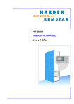
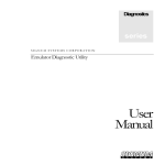
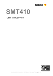
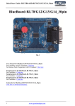
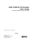
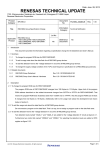
DSP
series
SIGNUM SYSTEMS CORPORATION
JTAGjet-TMS
User
Manual
COPYRIGHT NOTICE
Copyright (c) 2005 by Signum Systems Corporation. All rights are reserved worldwide. No part of this
publication may be reproduced, transmitted, transcribed, stored in a retrieval system, or translated into
any language or computer language, in any form or by any means, electronic, mechanical, magnetic,
optical, chemical, manual, or otherwise, without the prior written permission of Signum Systems.
DISCLAIMER
Signum Systems makes no representations or warranties with respect to the contents hereof and
specifically disclaims any implied warranties of merchantability or fitness for any particular purpose.
Also, Signum Systems reserves the right to revise this publication and to make changes from time to
time in the content hereof without obligation of Signum Systems to notify any person or organization
of such revision or changes.
WARRANTY
Signum Systems warrants to the original purchaser that this product is free of defects in material and
workmanship and performs to applicable published Signum Systems specifications for a period of SIX
MONTHS from the date of shipment. If defective, the product must be returned to Signum Systems,
prepaid, within the warranty period, and it will be repaired or replaced (at our option) at no charge.
Equipment or parts which have been subject to misuse, abuse, alteration, neglect, accident,
unauthorized installation or repair are not covered by warranty. This warranty is in lieu of any other
warranty expressed or implied. IN NO EVENT SHALL SIGNUM SYSTEMS BE LIABLE FOR
CONSEQUENTIAL DAMAGES OF ANY KIND. It is up to the purchaser to determine the
reliability and suitability of this product for his particular application.
11992 CHALLENGER COURT
MOORPARK, CA 93021, U.S.A
PHONE 805 • 523 • 9774
W W W . S I G N U M . C O M
UMC-JTAGjet-TMS 11.7.05.18.12 730
Table of Contents
C H A P T E R
1
Introduction
C H A P T E R
1
2
Installation
2
System Requirements
2
Software Installation
3
Hardware Installation
3
C H A P T E R
3
Emulator Features
4
External Characteristics
4
JTAGjet-TMS
4
JTAG Adapter for TMS320
6
A P P E N D I X
Appendix
7
Troubleshooting
7
i
1
Chapter
Introduction
DSP Development System basics.
J
(sometimes referred to as emulators) have the best
cost/performance ratio of tools for developing, debugging and analyzing the
software along with the hardware components of a microprocessor, microcontroller,
or DSP-based system. JTAG emulators provide the highest run-time performance
for debugging regression testing, hardware-software co-verification and system-level
verification.
TAG In-Circuit Debuggers
Unlike Ethernet or serial port, monitor based debuggers, JTAG in-circuit debugger is
totally transparent to the application and allows debugging without changing the
application S/W or adding restrictions to the H/W. No additional code
instrumentation or special software monitors are needed. The bottom line is a shorter
development cycle with increased code reliability.
How does it work? The TMS320 DSPs contain a specially designed Joint Test Action
Group (JTAG) compliant modules dedicated specifically for debugging. Its discrete
port provides information about the processor, its memory and the internal registers.
The emulator acts as a processing engine inserted between the target system and the
user’s computer. It communicates with the target application board through the
dedicated JTAG interface, captures the data, converts it into a format interpretable by
the computer and sends it to the PC through the USB port. Here the data is presented
to the design engineer in a graphical or other human readable form.
1
SI GNUM
2
S YS TE MS
Chapter
Installation
System Requirements
Your computer must be running Windows 98SE, ME, 2000 or XP and have one spare
USB 2.0 port available. USB 1.1 ports are not recommended because of slow speed.
The shipping package should contain the following:
1.
JTAGjet-TMS in-circuit debugger (emulator)
2.
JTAG cable with 14-pin JTAG probe (pinout for TMS320 devices)
3.
Signum Systems Development Tools CD-ROM with the necessary software (CCS
drivers for C2000 or Flasher-C2000 or both)
4.
USB 2.0 (type A/B) cable
5.
Installation instructions.
USB Driver Installation.
The USB drivers are installed during the CCS Drivers or Flasher software installation.
When you connect JTAGjet-TMS emulator to the computer, you will be asked for the
location of the USB device driver. If the Signum CD-ROM is in the drive, simply
accept the default settings. Otherwise, browse to the installation folder and select the
SigUSB.inf file. For instance, if C:\TI\C2000 was the CCS main folder, the Signum
2
J T AG J E T- TM S
U S E R
driver
information
file
would
be
C:\TI\C2000\drivers\Signum\Drivers\USB.
located
in
the
M A N U A L
subfolder
Please consult the “USB 2.0 Driver for JTAGjet Installation Instructions” document
(also available on at www.signum.com/tecdoc.htm) in case you have any problems
during the USB driver installation process.
Software Installation
To install software for the JTAGjet-TMS, please insert the CD-ROM and follow the
instructions printed on the Installation Instructions.
Hardware Installation
1.
Before connecting the JTAGjet-TMS to the target, please make sure that both the
emulator and the target are turned OFF.
2.
Connect the white JTAG cable with 14-pin adapter at the end to the emulator first.
3.
Connect the 14-pin JTAG adapter to the target board. The JTAG header on the
target board must have pin 6 missing so please make sure you are plugging into the
right connector.
4.
Connect JTAGjet-TMS to the PC. This will power the emulator. (NOTE: some
very old laptops with early USB 1.1 interfaces may not have enough power to
supply the emulator. In these vary rare cases, use a USB hub with external power
supply or apply 5V- 300mA power directly to the JTAGjet-TMS through the small,
round opening near the USB connector.
5.
Power-up the target board. The JTAG LED on the JTAGjet-TMS will turn-on
when the power is applied to the target.
3
3
Chapter
Emulator Features
Getting familiar with your emulator.
External Characteristics
JTAGjet-TMS
USB 2.0
interface
JTAG Adapter
and Cable
Status
LED
Figure 1 JTAGjet emulator.
Target power &
JTAG activity
LED
4
Host activity
LED
J T AG J E T- TM S
U S E R
M A N U A L
JTAGjet-TMS emulator has three LED indicators for monitoring various aspects of the
units’ operations, as specified in Table 1.
L E D
I N D I C A T O R
D E S C R I P T I O N
JTAG
Monitors the JTAG line.
• Stable ON: target powered, no data transfer on JTAG.
• Stable OFF: target not powered.
• Blinking: data transmission on JTAG.
1. Monitors the CPU status when the debugger has
established communication with the emulator.
• ON: CPU is running
• OFF: CPU in HALT state.
2. Monitors the emulator’s power when the debugger is
disconnected form the emulator.
Monitors the link to the host computer.
• ON: debugger established connection.
• OFF: no debugger-emulator connection.
• Blinking: data transfer between PC and emulator in
progress.
Status
Host
TABLE 1 JTAGjet LED functionality.
5
SI GNUM
S YS TE MS
JTAG Adapter for TMS320
JTAGjet-TMS is shipped with the ADA-JTAG-TMS adapter, which provides a physical
interface between JTAGjet emulator and TMS320 based target boards. It has 14-pin
double-row, polarized, .100" × .100". (2.54 mm × 2.54 mm) receptacles (female
connectors). The pinout and dimensions of the adapter are shown below.
TMS
1
2
TRST
TDI
3
4
GND
PD
5
6
KEY (no pin)
TDO
7
8
GND
TCK_RET
9
10
GND
TCK
11
12
GND
EMU0
13
14
EMU1
FIGURE 2 Pinout of the 14-pin JTAGjet adapter for
TMS320 (top view).
The probe automatically adjusts to the target board’s voltage on the JTAG port in the
range from 2.8V to 5V. The correct voltage must be connected to the PD pin-5.
Optionally, JTAGjet-TMS may be ordered with a low-voltage variant of the adapter, the
ADA-JTAG-TMS-LV, which operates in the 1.4V to 4.5V range.
6
J T AG J E T- TM S
U S E R
M A N U A L
Cable to Emulator
FIGURE 3 Dimensions of the 14-pin JTAGjet adapter
FIGURE 4 Dimensions of the 14-pin JTAGjet adapter for
for TMS320. Top view. A = 18.5 mm (0.73 in.) [lowvoltage: 23.0 mm (0.9 in.)], B = 18.3 mm (0.72 in.).
TMS320. Side view. C = 24.4 mm (.96 in.), D = 14.2 mm (0.56
in.), E = 8.5 mm (0.33 in.).
Appendix
Troubleshooting
1.
Make sure that the JTAG clock does not exceed the recommended
value for the target board. The JTAG clock should not be faster than
1/3 of the DSP frequency. Some DSPs start up at a very low clock
speed, so if you have JTAG communication errors please adjust the
JTAG clock speed using SignumCCS.exe utility (if running under CCS).
2.
Use AutoDetect in the SignumCCS program to test your scan chain.
The device list in the CCStudio Setup may be incorrect due to
modifications or mistakes.
3.
Make sure the board is properly initialized by a GEL file. Do that by
selecting the correct board and CCStudio GEL script file during the
7
SI GNUM
S YS TE MS
CCStudio setup process, or by running an initialization GEL script
manually from within CCStudio.
Technical Support
Technical Support by dialing (805) 523-9774, Monday
through Friday between 9 A.M. and 5 P.M. Pacific Time. In order to enable our
technical support engineers to process your request efficiently, we strongly
recommend submitting the Technical Support Request form available at
www.signum.com/support.htm. Our support team can also be reached by
email at [email protected].
Contact Signum Systems
We will be able to serve you better if, when contacting our Tech Support, you
are at your computer, have your documentation at hand and are prepared to
provide:
1.
The serial number and version of your Signum Systems software or
hardware that you are using.
2.
The exact wording of any messages and prompts that appear on your
screen.
3.
A description of what happened and what you were doing when the
problem occurred.
4.
In some cases we can connect remotely to your PC and see the problem.
This is the fastest way for us to help you in complicated situations, so
please make sure you have access to Internet when you call for help.
For more information about our products & data sheets please visit our home
page at www.signum.com .
To
download
technical
www.signum.com/tecdoc.htm
documentation,
UMB-JTAGjet-TMS 11.7.05.17.47 730
8
please
visit