1
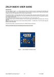
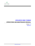
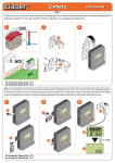
MODEL: PT761038
DOMESTIC LANTERN CCTV
SECURITY SYSTEM
with AUDIO & MOVEMENT ACTIVATION
USER MANUAL
IMPORTANT
READ THESE INSTRUCTIONS BEFORE USE
AND RETAIN FOR FUTURE REFERENCE.
Ultimate Products Limited
Manor Mill
Victoria Street
Chadderton
Oldham OL9 0DD
PARTS & ACCESSORIES
1 x 230V Lantern with Built in PIR Camera (1)
1 x Control Unit with Intercom (2)
1 x 17M 6-Pin Mini ‘DIN’ Extension Cable for Lantern to Control Unit (3)
1 x 1.5M DIN-SCART Connection Cable (4)
1 x 15v DC 500mA Mains Adaptor (5)
Mounting Accessories
2
INSTALLATION INSTRUCTIONS
The PT761038 is an easily-installed security system that consists of one
lamp lantern camera with built-in PIR sensor, 2-way intercom,
audio/movement trigger and control unit.
The lantern camera unit is under shade. This lantern camera CCTV
system simply plugs into the ‘SCART’ socket of a standard TV, where it
automatically tunes itself into the ‘AV’ channel. The TV will display the
camera view whenever it is activated by the PIR, audio trigger, or the
‘intercom’ button being pressed (providing your television has ‘Auto Scart
triggering’).
The lantern camera unit is also built-in with a light sensor. When day light
is getting dark, it will automatically turn the lamp ON.
Important:
The security system will only ‘auto trigger’ via the scart socket of the
television, which the PT761038 scart plug is connected to, and only if the
TV has auto triggering through its scart socket. Please refer to your
television manual for this information.
PLEASE NOTE:
If the scart plug is connected to the VCR and not the television, the auto
triggering of the AV channel is unavailable; this is due to the wiring of the
VCR scart socket.
WARNING:
Max. 100W or below light bulb power
3
Installinq the Lantern Camera
Step I
Put the Lamp Housing on the top of Base Unit,
and screw in the fixing ring to until hold tight.
Step 2
Insert the light bulb (not supplied in the
package).
Step 3
Insert the 6 pieces lamp transparent lens into the
Lamp Housing.
Fixing Rlitg
Light Bulb not
supplied)
Lens
lens
Step 4
Insert the lamp cover and secure with the 2 8mm
screws supplied
2 x 8mm
Step 5
Unscrew the bottom base unit from the Lamp
Housing. To install the Base Unit to the wall,
Drill 2 holes and insert the screw anchors into
the wall.
Using the 2 x 25mm screws supplied secure
the base unit to the wall. Remember to pass
through the lamp AC supply wires and camera
to the supply 15m DIN extension cable.
Step 6
Connect the Lamp Light AC wires to the 2 AC
terminal poles.
Step 7
Screw back the Lamp Housing to the Base Unit
with the supplied nuts.
Connecting the System
-
-
Check that the Lantern Camera and control unit function properly
before installing!
Pick a position on a wall and mount the Lantern Camera.
Connect the ‘male’ plug on the Lantern Camera lead into the ‘female’
socket on the 15m extension cable.
Plug the other ‘male’ end into the socket on the back of the control
unit marked ‘CAM’.
Connect the Scart plug into the Scart socket on your TV and insert
the other end of the scart cable into the socket on the control unit
marked ‘TV’.
Plug the mains adaptor into the socket marked ‘DC 15V’, plug into an
appropriate mains socket and switch on.
The green LED will illuminate when the power is connected to the
control unit and will bleep twice if everything is functioning correctly.
IMPORTANT - When considering a location for the Lantern Camera,
note that:
1. The camera must not be focused to look directly into the sun (plot the
path from sunrise to sunset) or any other bright light source as this will
not only result in a poor image, but will eventually damage the
electronics of the camera.
2. Areas with a high degree of contrast in the light levels will require
careful siting of the camera to obtain the best image.
3. The best viewing angle is achieved by adjusting the camera in a
position where it is looking down on the subject.
4. When using the Lantern Camera at a door to monitor visitors, ensure
that it is not positioned too far away from the door otherwise the sound
of their speech will be impaired.
5
5. The Lantern Camera is not waterproof, therefore it recommended to
install in a sheltered position if possible.
OPERATION OF THE SYSTEM
Setting the trigger sources by switch position
OFF
If you do not want the control unit to automatically trigger, set
the switch to the ‘OFF’ position.
PIR
If the switch is put in the ‘PIR’ position the control unit will
only be triggered by movement in front of the camera.
AUDIO
If the switch is put to the ‘AUDIO’ position then only noise
picked up by the microphone in the camera will trigger the
unit.
PIR+AUDIO
If the switch is moved to the ‘PIR+AUDIO’ position then both
movement and noise will trigger the unit.
Setting the output status
OFF
If the switch is in the ‘OFF’ position the control unit will not be
triggered.
TV
If the switch is in the ‘TV’ position it will only trigger the
switching of the television onto the ‘AV’ channel.
ALARM
When the switch is in the ‘ALARM’ position, only the buzzer
will be activated on receiving a trigger from the camera. The
volume of the buzzer is not adjustable.
6
ALARM+TV
When the switch is in the ‘ALARM+TV’ position the buzzer
and the auto-triggering of the television will be activated when
triggered.
Intercom
This is a two-way communication between the cameras and the control
unit. When the camera view is shown on the television, you will be able
to hear the sound picked up by one of the cameras microphones. When
you want to speak to a person at the camera end of the system, simply
press the intercom button on the control unit, then speak into the control
unit. The intercom button will have to be released before the sound
picked up from the camera microphone is heard again.
LED Status Indicators
Power: Indicates the control unit is connected to its DC power supply.
TV:
Indicates the system is triggering the television.
Intercom:
Indicates the system 2-way communicating.
Setting Time ON
The time that the camera image stays on the television screen can be set
by the ‘TV ON TIME’ wheel (located on the side of the control unit). This
can range from 5 seconds to 30 seconds.
Setting the Trigger Level
The sensitivity of the trigger level of the microphone on the camera input
can be adjusted by the ‘Audio Level’ wheel (located on the side of the
control unit), to suit the surrounding ambient noise level.
7
Technical Specifications
Camera Unit
Camera Spec: CMOS
Focal Length: 3.6mm F2.0
Illumination: 1 Lux
Resolution : 250 TV Lines
View Angle: 70º
Working Temp’:
-10ºC to +45ºC
Input Power: 12V 300mA
Control Unit
TV ON Time: 5-30sec
Input Power: 15V 500mA
Connection Cable: 17 Metres
Configuaration: 6 Pin DIN-DIN
Scart Cable: 2 Metre (approx.)
Power Adapter:
Input Power 220V-240VAC
Output Power: 15V 500mA
Because our products are subject to continuous improvement, the manufacturer
reserves the right to modify product design and specifications without notice and
without incurring any obligation. E& OE.
8